Constraints Micro-fabrication Micro-physics …...Micro-fabrication Micro-physics scaling Assignment...
42
2.76 Multi-scale System Design & Manufacturing 2.76 / 2.760 Lecture 5: Large/micro scale Constraints Micro-fabrication Micro-physics scaling Assignment
Transcript of Constraints Micro-fabrication Micro-physics …...Micro-fabrication Micro-physics scaling Assignment...
2.76 Multi-scale System Design & Manufacturing
2.76 / 2.760 Lecture 5: Large/micro scaleConstraints
Micro-fabrication
Micro-physics scaling
Assignment
2.76 Multi-scale System Design & Manufacturing
Nano
Micro
Meso
Macro
NanoNano
NanoMicro
NanoMeso
NanoMacro
MicroNano
MicroMicro
MicroMeso
MicroMacro
MesoNano
MesoMicro
MesoMeso
MesoMacro
MacroNano
MacroMicro
MacroMeso
MacroMacro
Nano
Micro
Meso
Macro
I
I
I
I
SRfSRfSRfSRf
SRfSRfSRfSRf
SRfSRfSRfSRf
SRfSRfSRfSRf
O
O
O
O
⋅
⎟⎟⎠
⎞⎜⎜⎝
⎛⎟⎟⎠
⎞⎜⎜⎝
⎛⎟⎟⎠
⎞⎜⎜⎝
⎛⎟⎟⎠
⎞⎜⎜⎝
⎛
⎟⎟⎠
⎞⎜⎜⎝
⎛⎟⎟⎠
⎞⎜⎜⎝
⎛⎟⎟⎠
⎞⎜⎜⎝
⎛⎟⎟⎠
⎞⎜⎜⎝
⎛
⎟⎟⎠
⎞⎜⎜⎝
⎛⎟⎟⎠
⎞⎜⎜⎝
⎛⎟⎟⎠
⎞⎜⎜⎝
⎛⎟⎟⎠
⎞⎜⎜⎝
⎛
⎟⎟⎠
⎞⎜⎜⎝
⎛⎟⎟⎠
⎞⎜⎜⎝
⎛⎟⎟⎠
⎞⎜⎜⎝
⎛⎟⎟⎠
⎞⎜⎜⎝
⎛
=
44434241
34333231
24232221
14131211
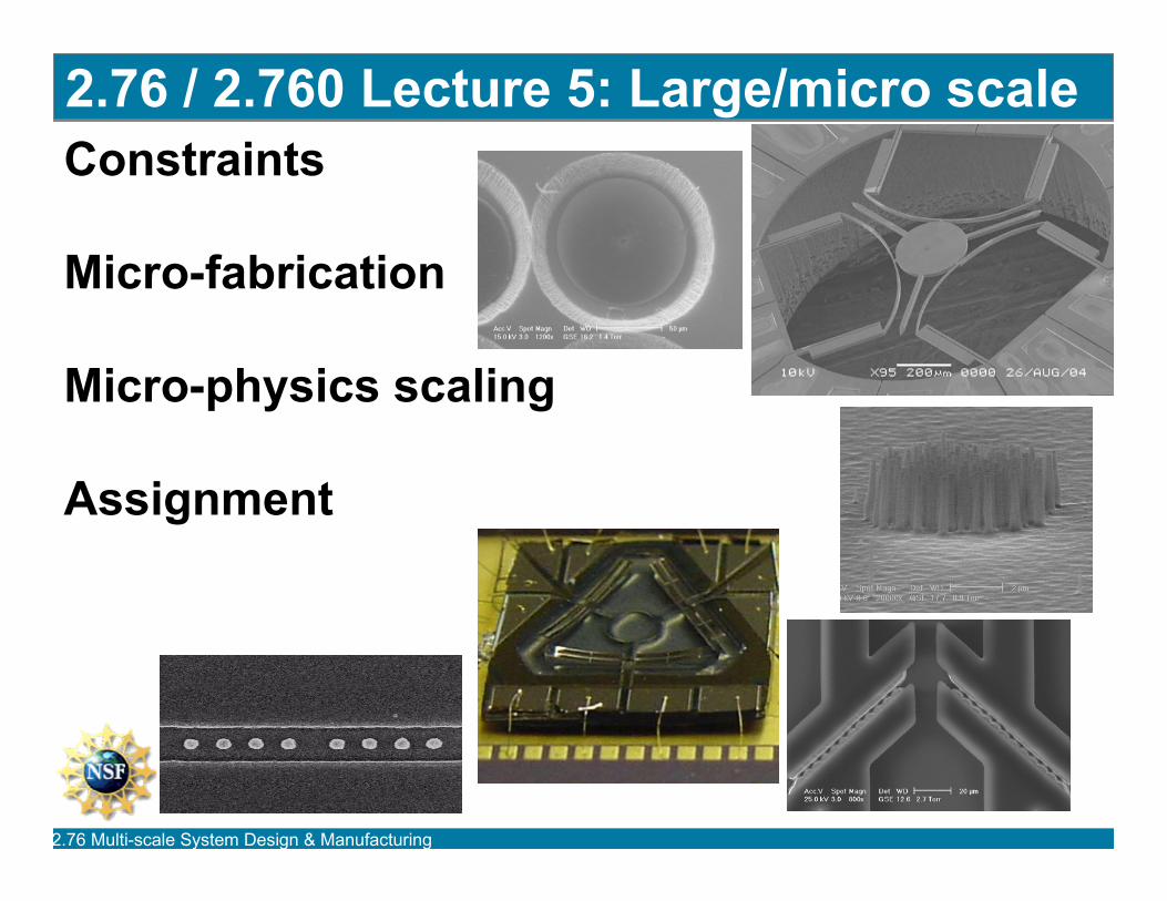
Purpose of today
Finish mechanical gain factors to make big machineswork with little machines
Micro-scale flow/interface dominators•Micro-scale fabrication•Micro-scale surface/volume physics
2.76 Multi-scale System Design & Manufacturing
Constraints
2.76 Multi-scale System Design & Manufacturing
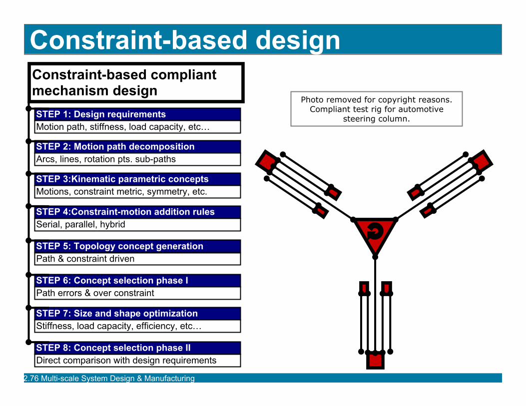
Constraint-based designConstraint-based compliant mechanism design
STEP 2: Motion path decomposition
STEP 3:Kinematic parametric concepts
STEP 4:Constraint-motion addition rules
STEP 5: Topology concept generation
STEP 6: Concept selection phase I
STEP 7: Size and shape optimization
STEP 8: Concept selection phase II
STEP 1: Design requirements
Arcs, lines, rotation pts. sub-paths
Motions, constraint metric, symmetry, etc.
Serial, parallel, hybrid
Path & constraint driven
Path errors & over constraint
Stiffness, load capacity, efficiency, etc…
Direct comparison with design requirements
Motion path, stiffness, load capacity, etc…
Photo removed for copyright reasons.Compliant test rig for automotive
steering column.
2.76 Multi-scale System Design & Manufacturing
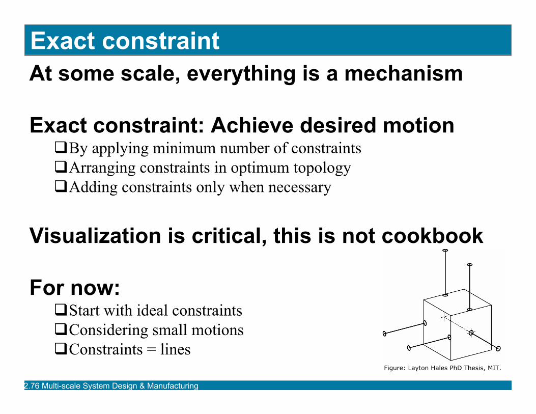
Exact constraintAt some scale, everything is a mechanism
Exact constraint: Achieve desired motionBy applying minimum number of constraintsArranging constraints in optimum topologyAdding constraints only when necessary
Visualization is critical, this is not cookbook
For now:Start with ideal constraintsConsidering small motionsConstraints = lines
Figure: Layton Hales PhD Thesis, MIT.
2.76 Multi-scale System Design & Manufacturing
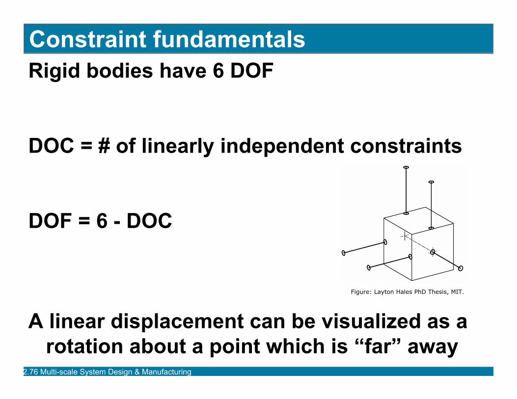
Constraint fundamentalsRigid bodies have 6 DOF
DOC = # of linearly independent constraints
DOF = 6 - DOC
A linear displacement can be visualized as a rotation about a point which is “far” away
Figure: Layton Hales PhD Thesis, MIT.
2.76 Multi-scale System Design & Manufacturing
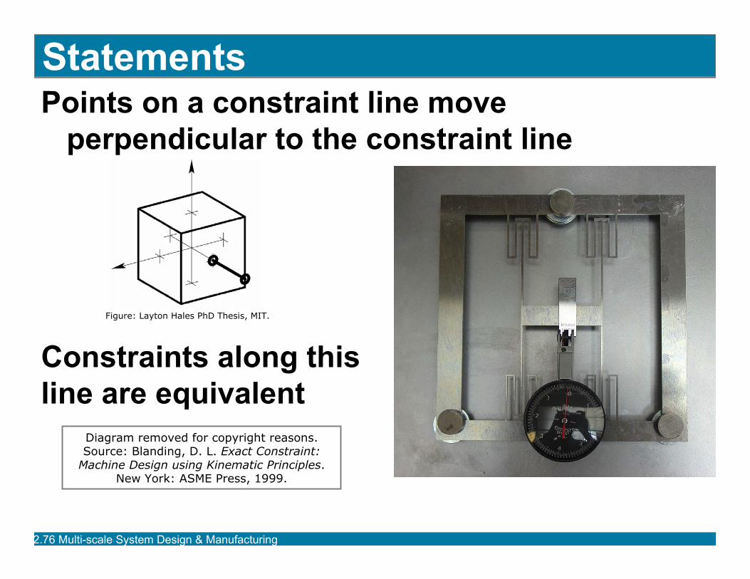
Points on a constraint line move perpendicular to the constraint line
Constraints along thisline are equivalent
Statements
Diagram removed for copyright reasons.Source: Blanding, D. L. Exact Constraint:
Machine Design using Kinematic Principles. New York: ASME Press, 1999.
Figure: Layton Hales PhD Thesis, MIT.
2.76 Multi-scale System Design & Manufacturing
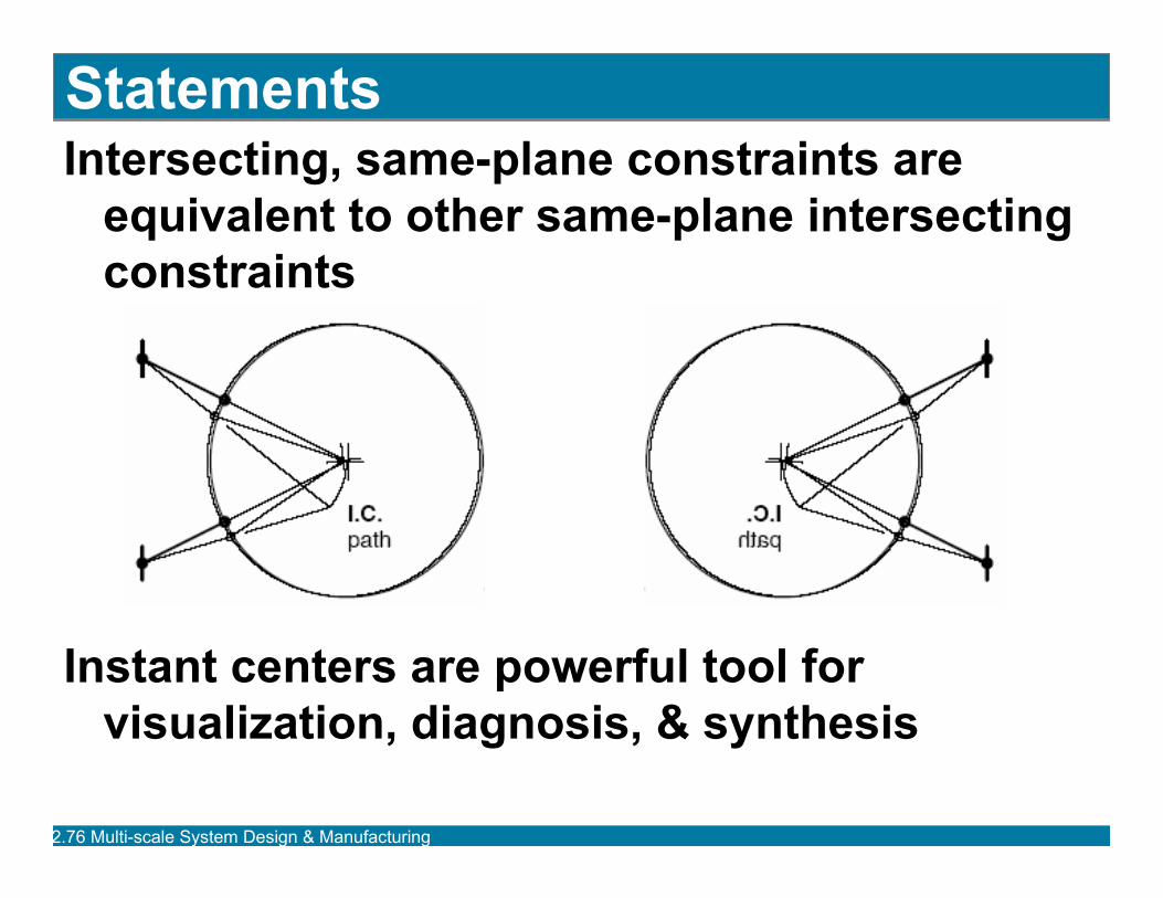
StatementsIntersecting, same-plane constraints are
equivalent to other same-plane intersecting constraints
Instant centers are powerful tool for visualization, diagnosis, & synthesis
2.76 Multi-scale System Design & Manufacturing
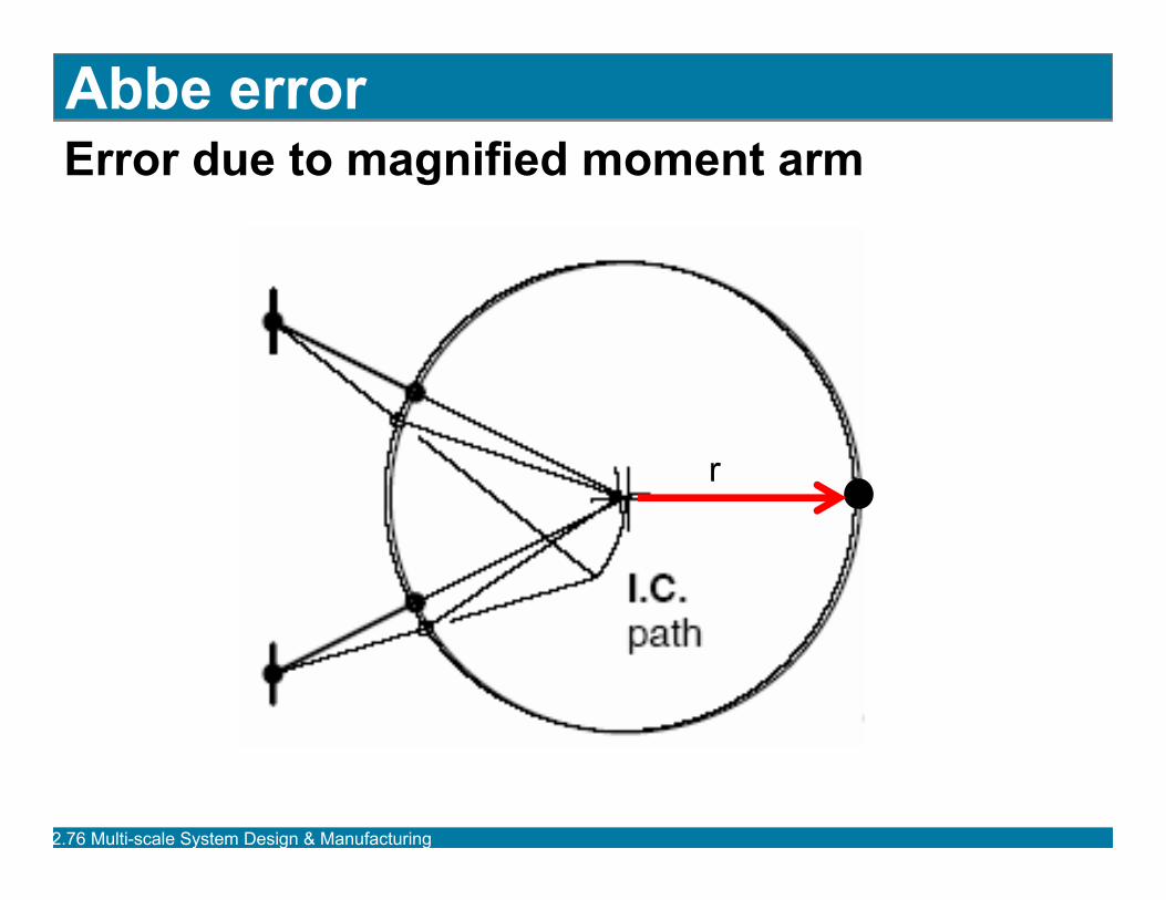
Abbe errorError due to magnified moment arm
r
2.76 Multi-scale System Design & Manufacturing
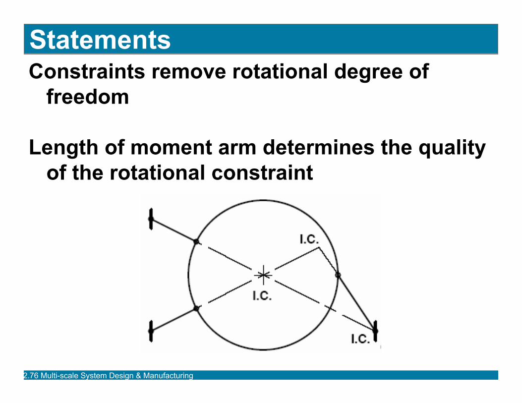
StatementsConstraints remove rotational degree of
freedom
Length of moment arm determines the quality of the rotational constraint
2.76 Multi-scale System Design & Manufacturing
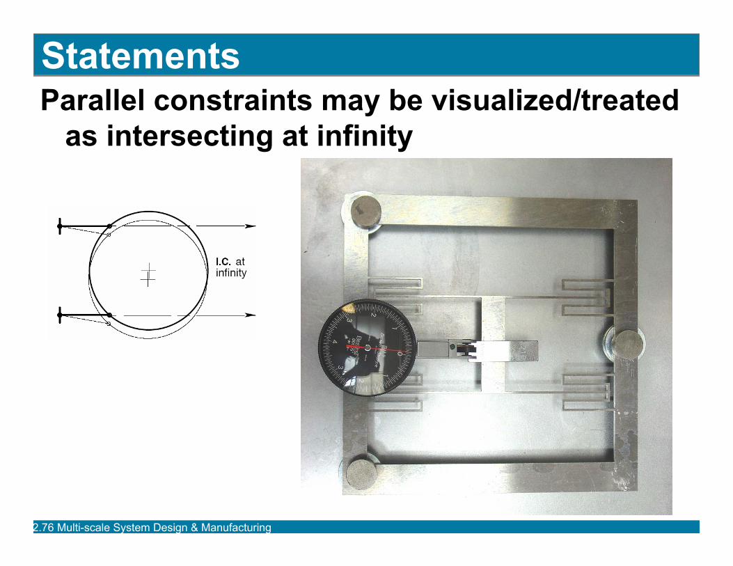
StatementsParallel constraints may be visualized/treated
as intersecting at infinity
2.76 Multi-scale System Design & Manufacturing
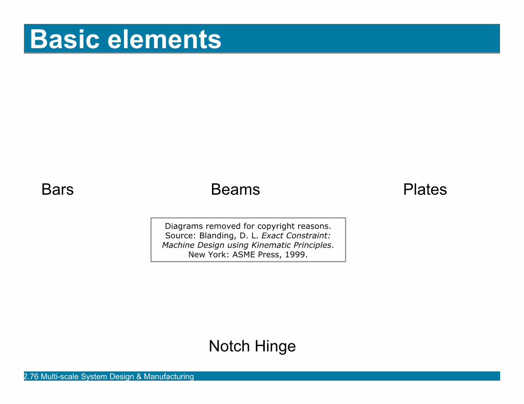
Basic elements
Bars Beams Plates
Notch Hinge
Diagrams removed for copyright reasons.Source: Blanding, D. L. Exact Constraint:
Machine Design using Kinematic Principles. New York: ASME Press, 1999.
2.76 Multi-scale System Design & Manufacturing
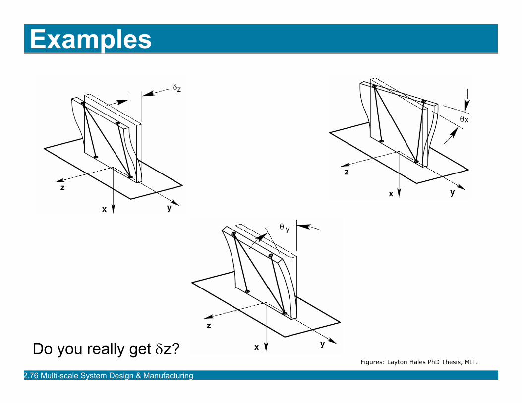
Examples
Do you really get δz?Figures: Layton Hales PhD Thesis, MIT.
2.76 Multi-scale System Design & Manufacturing
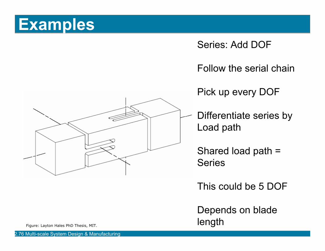
ExamplesSeries: Add DOF
Follow the serial chain
Pick up every DOF
Differentiate series byLoad path
Shared load path =Series
This could be 5 DOF
Depends on blade lengthFigure: Layton Hales PhD Thesis, MIT.
2.76 Multi-scale System Design & Manufacturing
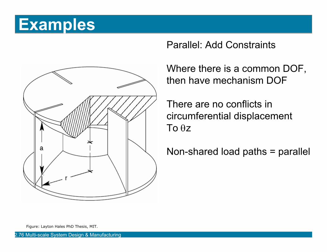
ExamplesParallel: Add Constraints
Where there is a common DOF,then have mechanism DOF
There are no conflicts incircumferential displacementTo θz
Non-shared load paths = parallel
Figure: Layton Hales PhD Thesis, MIT.
2.76 Multi-scale System Design & Manufacturing
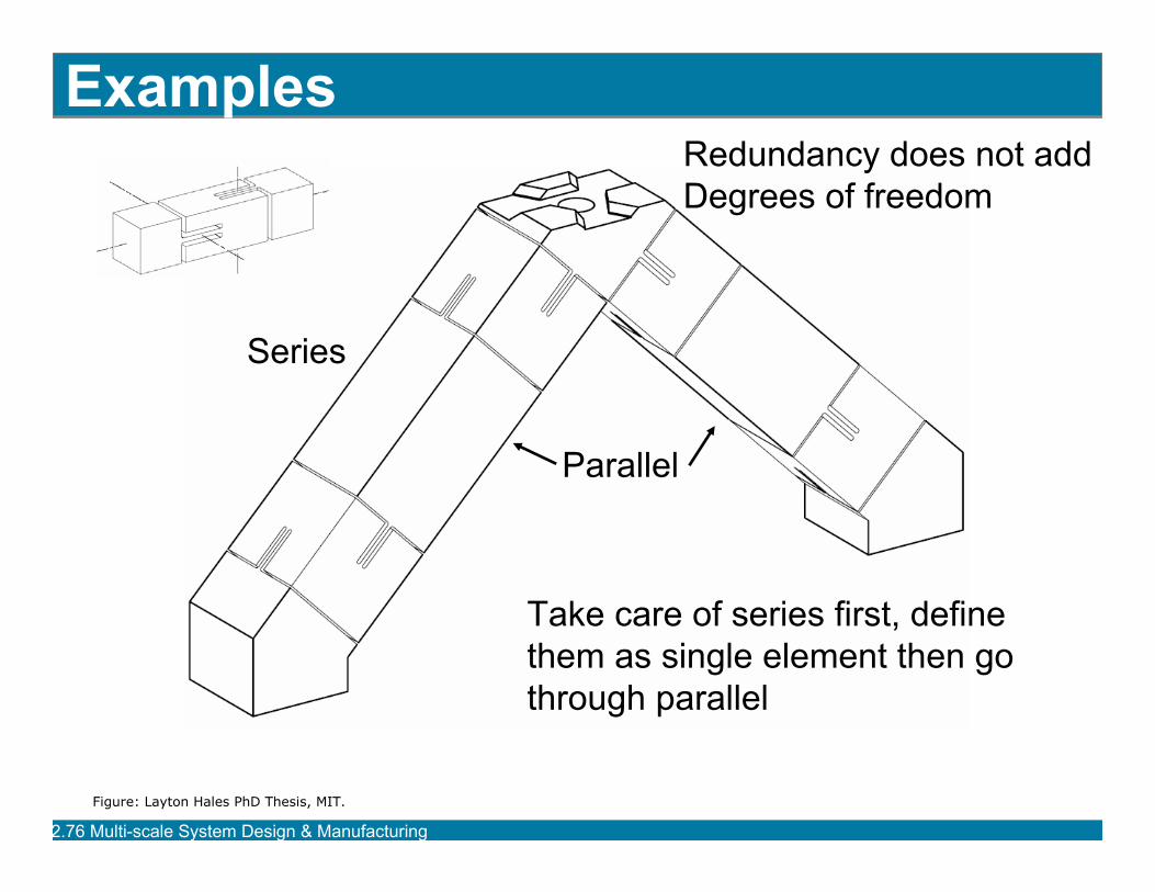
Examples
Take care of series first, definethem as single element then gothrough parallel
Series
Parallel
Redundancy does not addDegrees of freedom
Figure: Layton Hales PhD Thesis, MIT.
2.76 Multi-scale System Design & Manufacturing
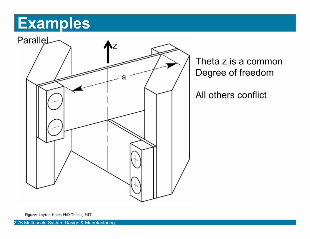
Examples
Theta z is a commonDegree of freedom
All others conflict
zParallel
Figure: Layton Hales PhD Thesis, MIT.
2.76 Multi-scale System Design & Manufacturing
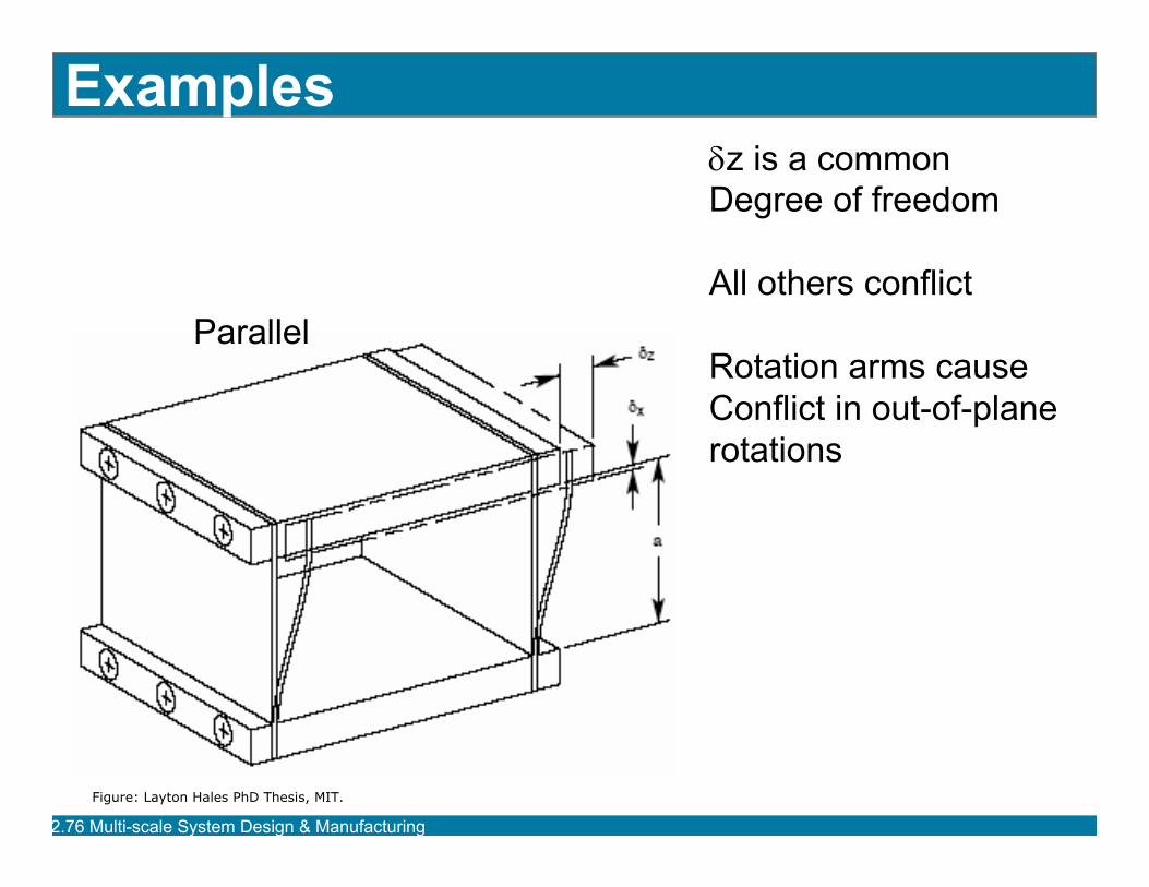
Examplesδz is a commonDegree of freedom
All others conflict
Rotation arms causeConflict in out-of-planerotations
Parallel
Figure: Layton Hales PhD Thesis, MIT.
2.76 Multi-scale System Design & Manufacturing
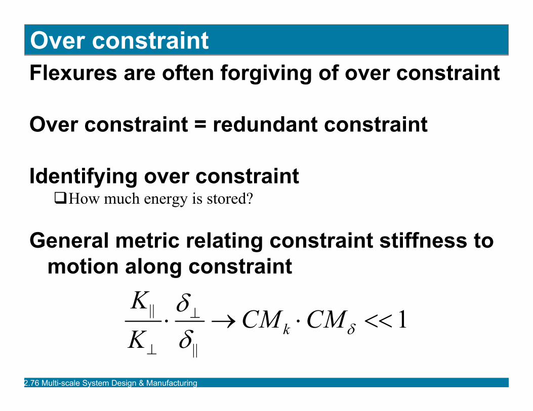
Over constraintFlexures are often forgiving of over constraint
Over constraint = redundant constraint
Identifying over constraintHow much energy is stored?
General metric relating constraint stiffness to motion along constraint
1||
|| <<⋅→⋅ ⊥
⊥δδ
δ CMCMKK
k
2.76 Multi-scale System Design & Manufacturing
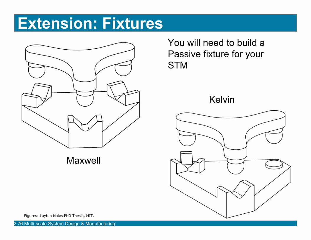
Extension: Fixtures
Maxwell
Kelvin
You will need to build a Passive fixture for your STM
Figures: Layton Hales PhD Thesis, MIT.
2.76 Multi-scale System Design & Manufacturing
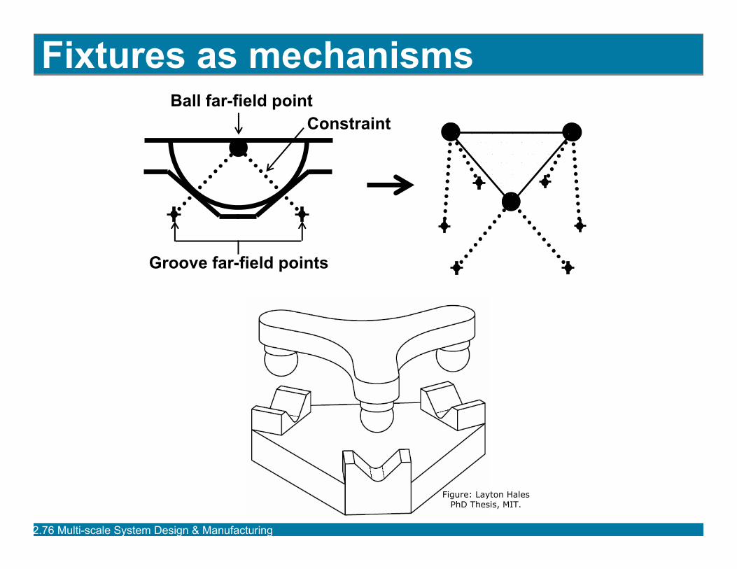
Fixtures as mechanismsBall far-field point
Groove far-field points
Constraint
Figure: Layton Hales PhD Thesis, MIT.
2.76 Multi-scale System Design & Manufacturing
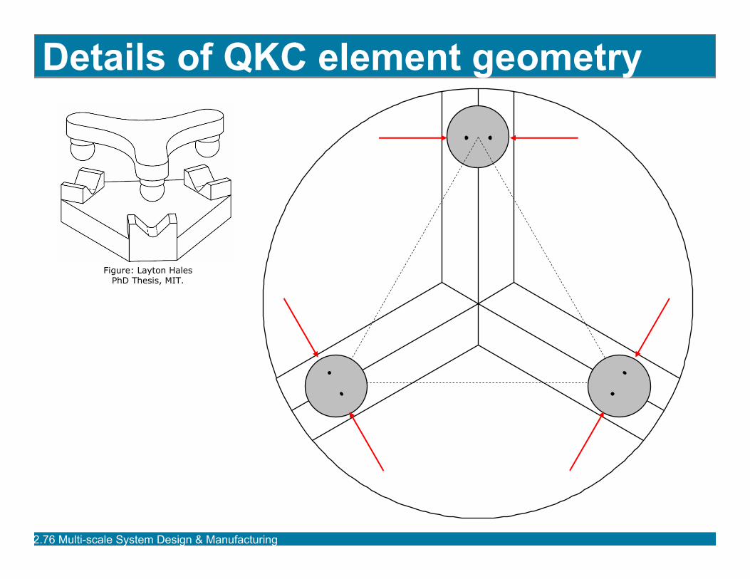
Details of QKC element geometry
Figure: Layton Hales PhD Thesis, MIT.
2.76 Multi-scale System Design & Manufacturing
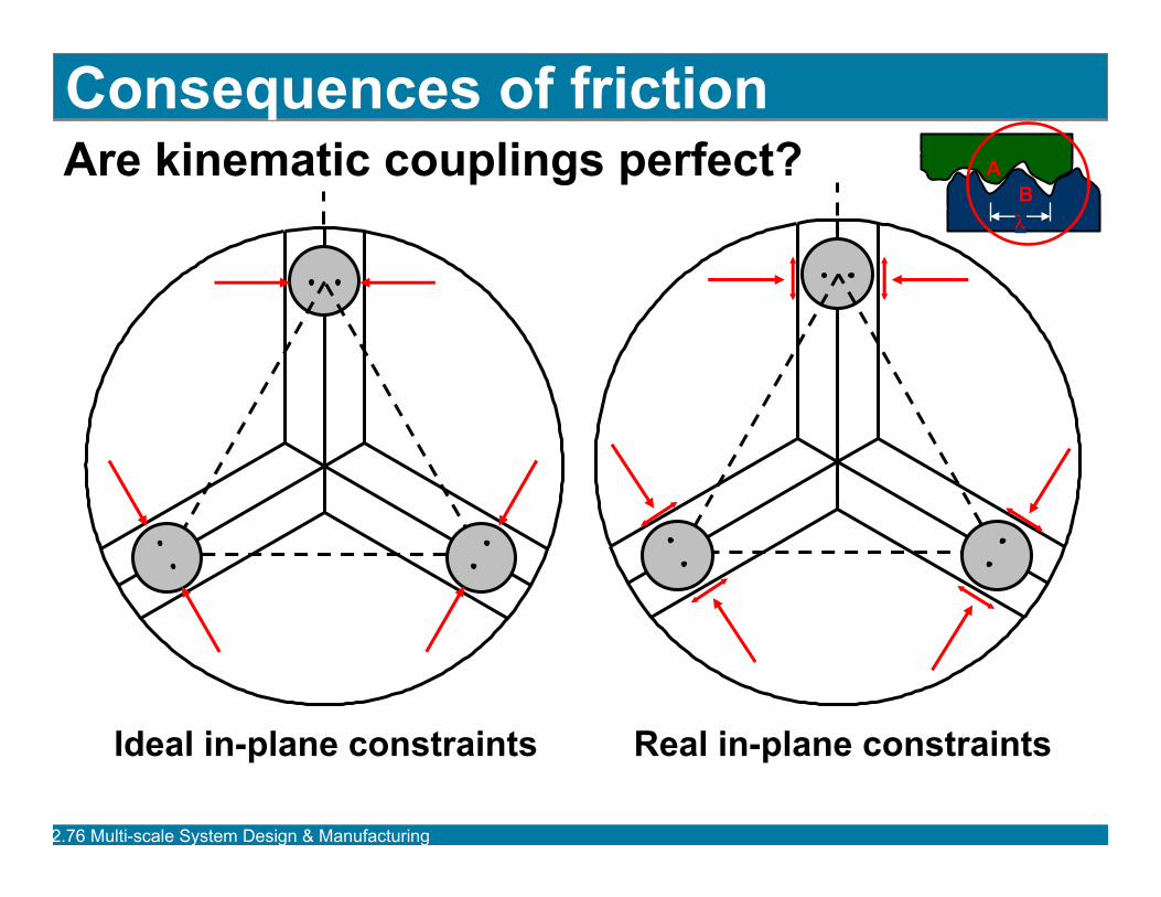
Are kinematic couplings perfect?Consequences of friction
Ideal in-plane constraints Real in-plane constraints
BA
λ
2.76 Multi-scale System Design & Manufacturing
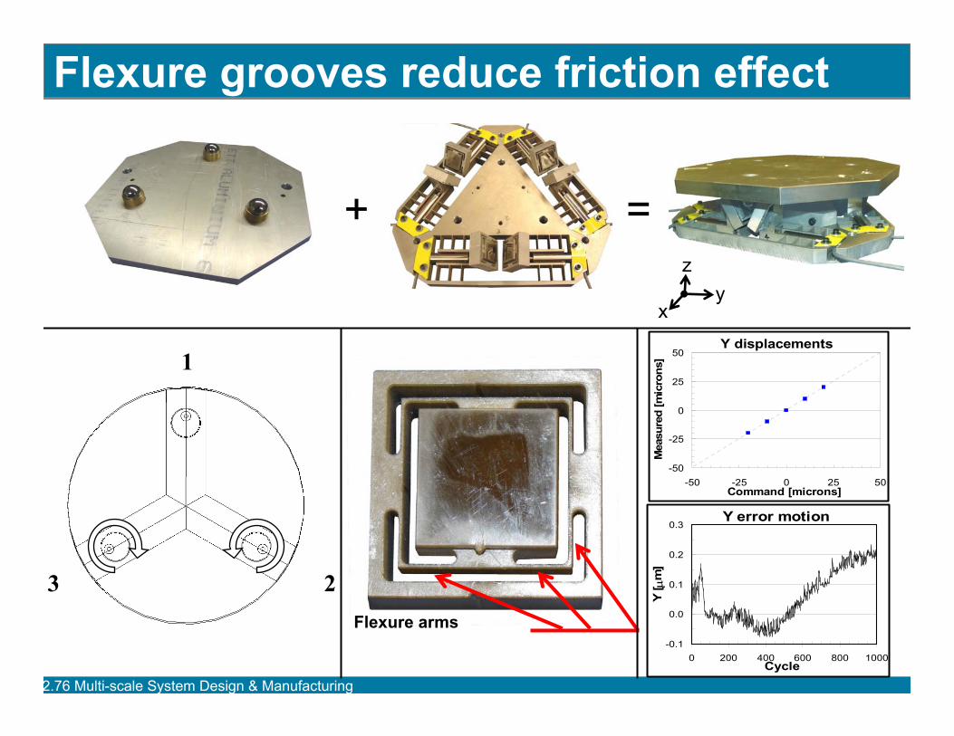
Flexure arms
Flexure grooves reduce friction effect
1
23
Y displacements
-50
-25
0
25
50
-50 -25 0 25 50Command [microns]
Mea
sure
d [m
icro
ns]
Y error motion
-0.1
0.0
0.1
0.2
0.3
0 200 400 600 800 1000Cycle
Y [ µ
m]
+ =
yx
z
2.76 Multi-scale System Design & Manufacturing
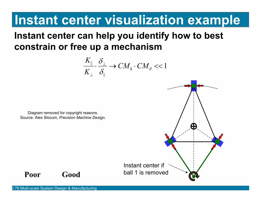
Instant center can help you identify how to best constrain or free up a mechanism
Instant center visualization example
PoorInstant center ifball 1 is removedGood
Diagram removed for copyright reasons.Source: Alex Slocum, Precision Machine Design.
1||
|| <<⋅→⋅ ⊥
⊥δδ
δ CMCMKK
k
2.76 Multi-scale System Design & Manufacturing
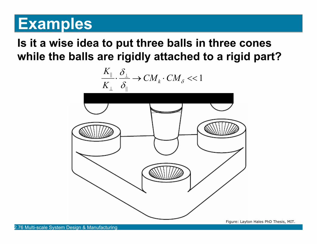
ExamplesIs it a wise idea to put three balls in three cones while the balls are rigidly attached to a rigid part?
1||
|| <<⋅→⋅ ⊥
⊥δδ
δ CMCMKK
k
Figure: Layton Hales PhD Thesis, MIT.
2.76 Multi-scale System Design & Manufacturing
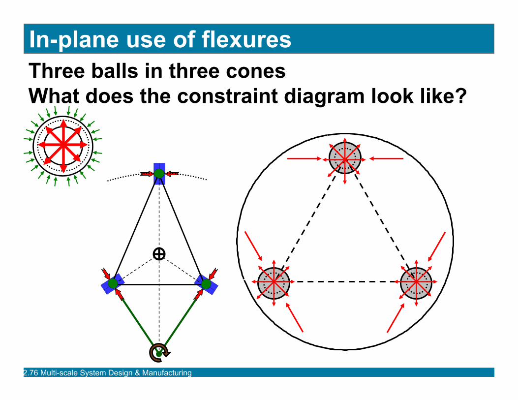
Three balls in three conesWhat does the constraint diagram look like?
In-plane use of flexures
2.76 Multi-scale System Design & Manufacturing
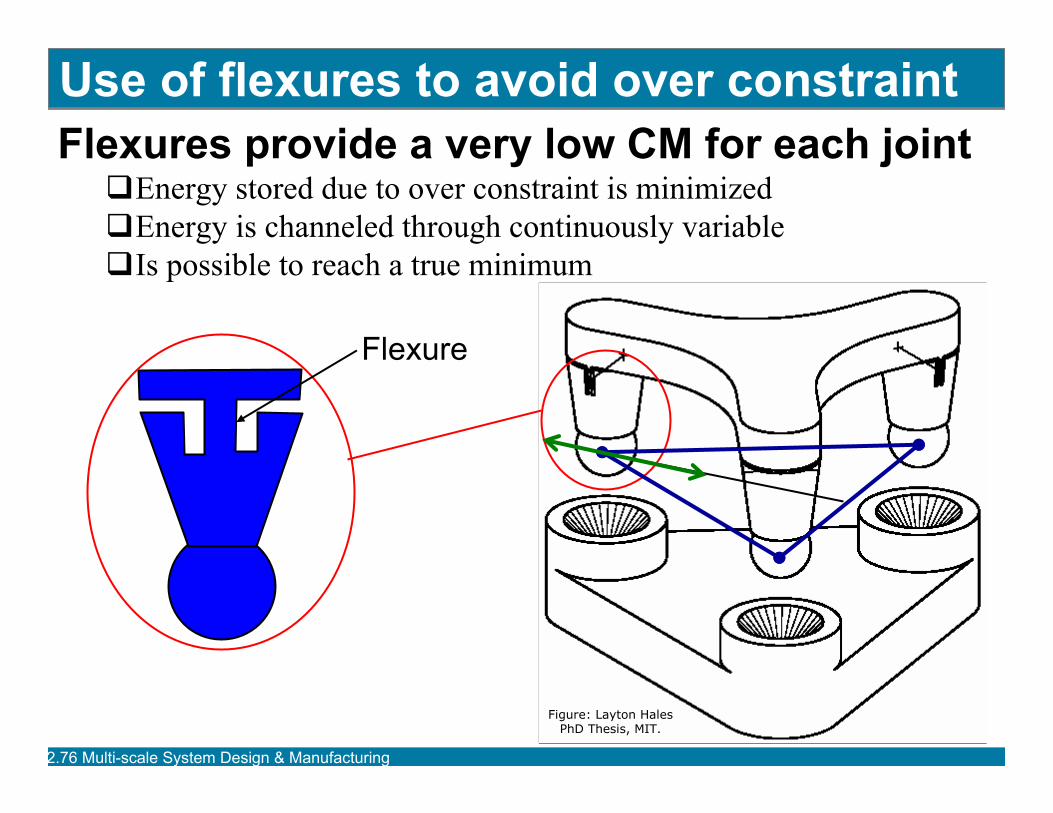
Use of flexures to avoid over constraintFlexures provide a very low CM for each joint
Energy stored due to over constraint is minimizedEnergy is channeled through continuously variableIs possible to reach a true minimum
Flexure
Figure: Layton Hales PhD Thesis, MIT.
2.76 Multi-scale System Design & Manufacturing
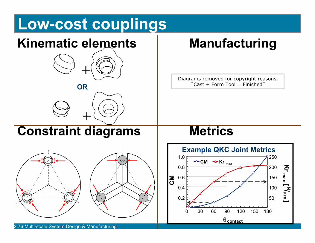
Kinematic elements Manufacturing
Constraint diagrams Metrics
+
+
OR
Low-cost couplings
Example QKC Joint Metrics
0.2
0.4
0.6
0.8
1.0
0 30 60 90 120 150 180
θcontact
CM
50
100
150
200
250
Kr m
ax [ N/µm ]
CM Kr max
Diagrams removed for copyright reasons.“Cast + Form Tool = Finished”
2.76 Multi-scale System Design & Manufacturing
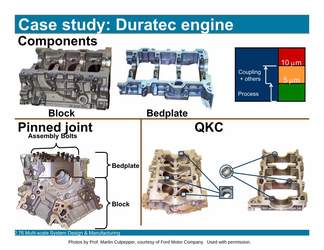
Components
Pinned joint QKC
Block
Bedplate
Assembly Bolts
Case study: Duratec engine
Block Bedplate
Coupling+ others
Process
10 µm
5 µm
Photos by Prof. Martin Culpepper, courtesy of Ford Motor Company. Used with permission.
2.76 Multi-scale System Design & Manufacturing
Micro-scale systems
2.76 Multi-scale System Design & Manufacturing
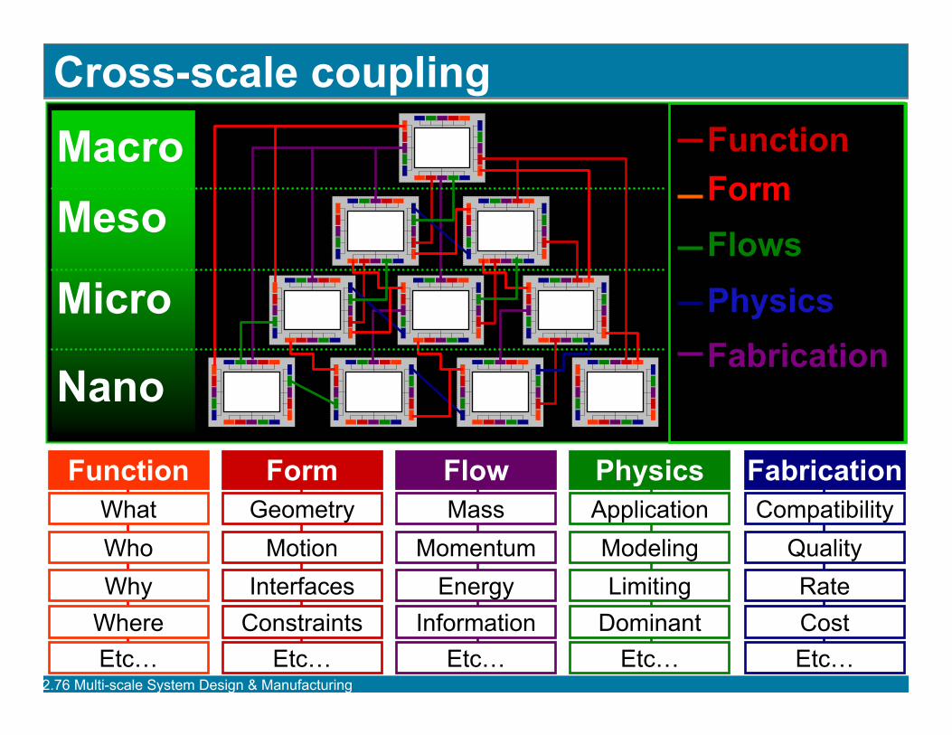
Cross-scale couplingMacroMeso
Micro
Nano
FunctionFormFlowsPhysicsFabrication
GeometryMotion
InterfacesConstraints
Form
Etc…
MassMomentum
EnergyInformation
Flow
Etc…
ApplicationModelingLimiting
Dominant
Physics
Etc…
CompatibilityQualityRateCost
Fabrication
Etc…
WhatWhoWhy
Where
Function
Etc…
2.76 Multi-scale System Design & Manufacturing
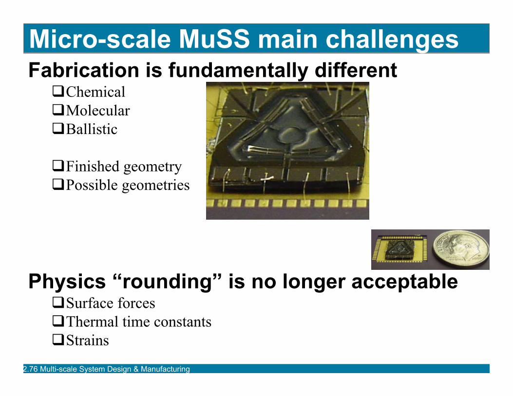
Micro-scale MuSS main challengesFabrication is fundamentally different
ChemicalMolecularBallistic
Finished geometryPossible geometries
Physics “rounding” is no longer acceptableSurface forcesThermal time constantsStrains
2.76 Multi-scale System Design & Manufacturing
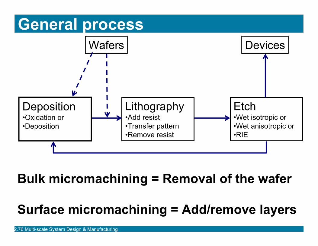
General process
Deposition•Oxidation or•Deposition
Lithography•Add resist•Transfer pattern•Remove resist
Etch•Wet isotropic or•Wet anisotropic or•RIE
DevicesWafers
Bulk micromachining = Removal of the wafer
Surface micromachining = Add/remove layers
2.76 Multi-scale System Design & Manufacturing
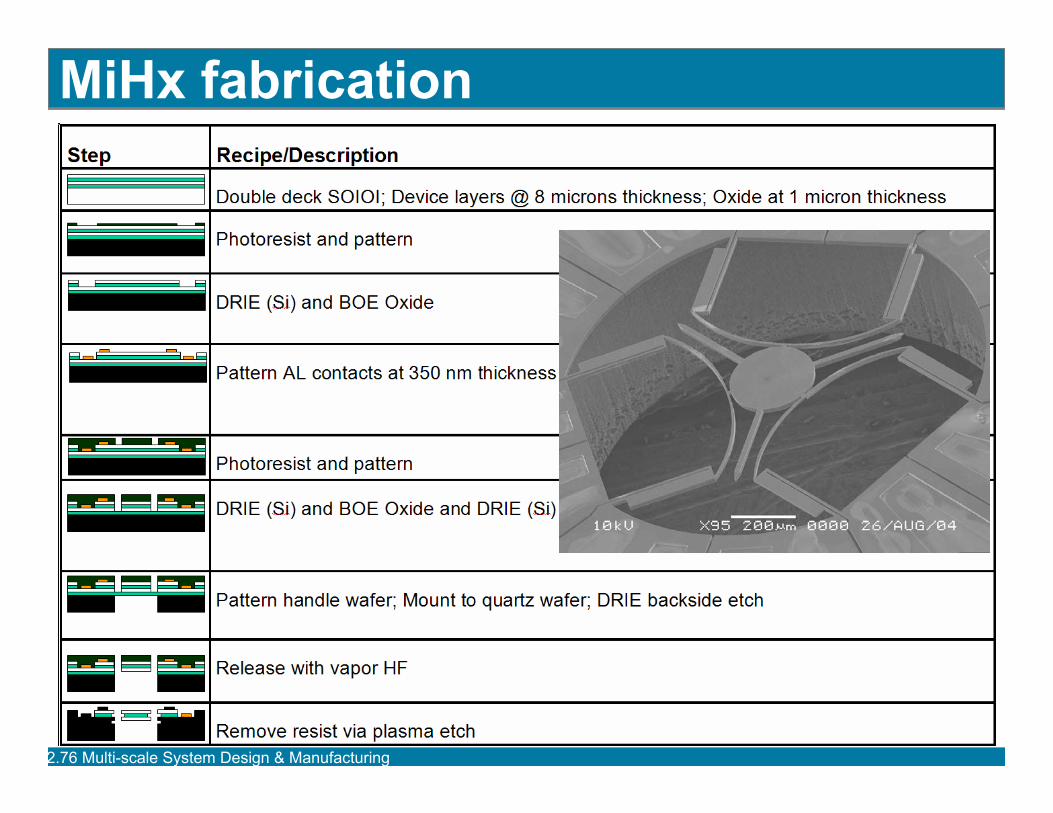
MiHx fabrication
2.76 Multi-scale System Design & Manufacturing
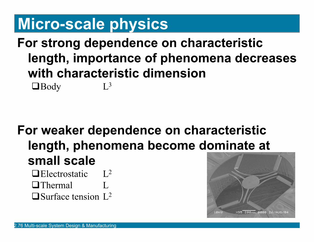
Micro-scale physicsFor strong dependence on characteristic
length, importance of phenomena decreases with characteristic dimension
Body L3
For weaker dependence on characteristic length, phenomena become dominate at small scale
Electrostatic L2
Thermal LSurface tension L2
2.76 Multi-scale System Design & Manufacturing
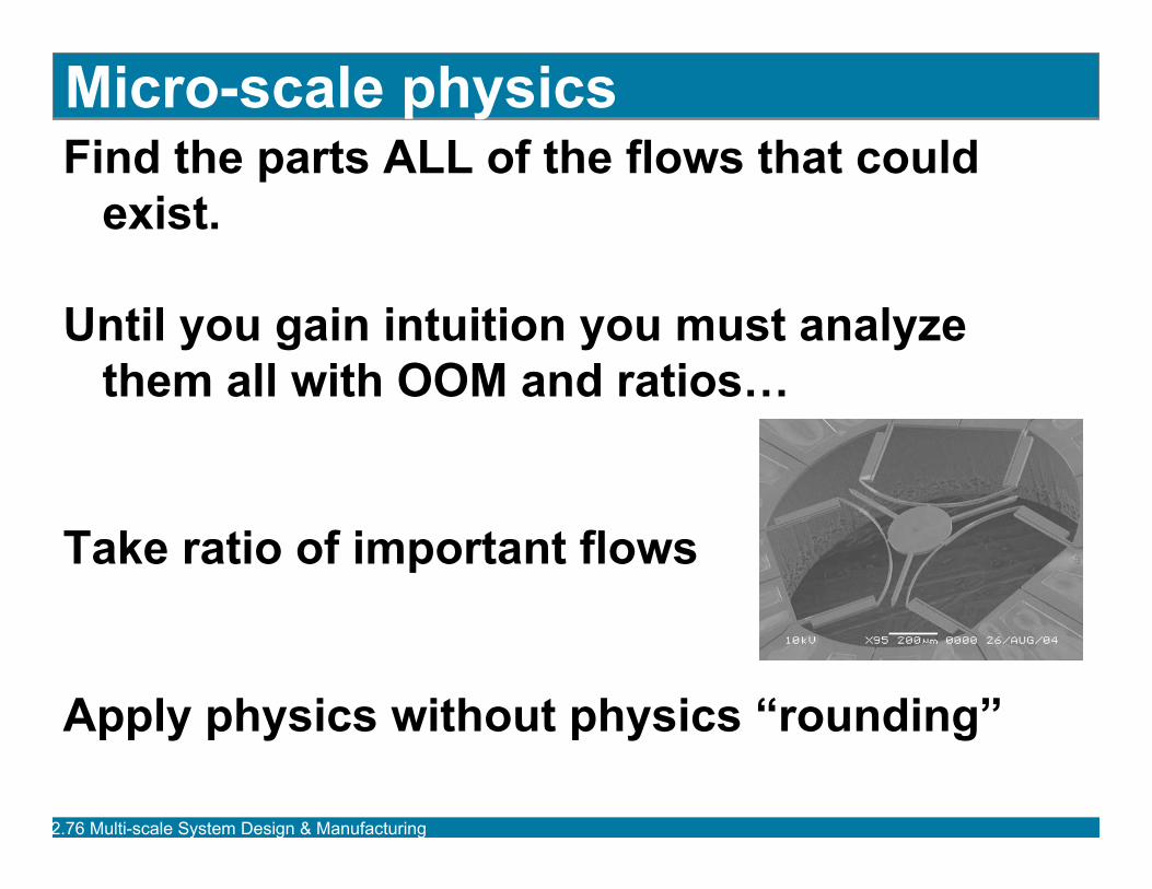
Micro-scale physicsFind the parts ALL of the flows that could
exist.
Until you gain intuition you must analyze them all with OOM and ratios…
Take ratio of important flows
Apply physics without physics “rounding”
2.76 Multi-scale System Design & Manufacturing
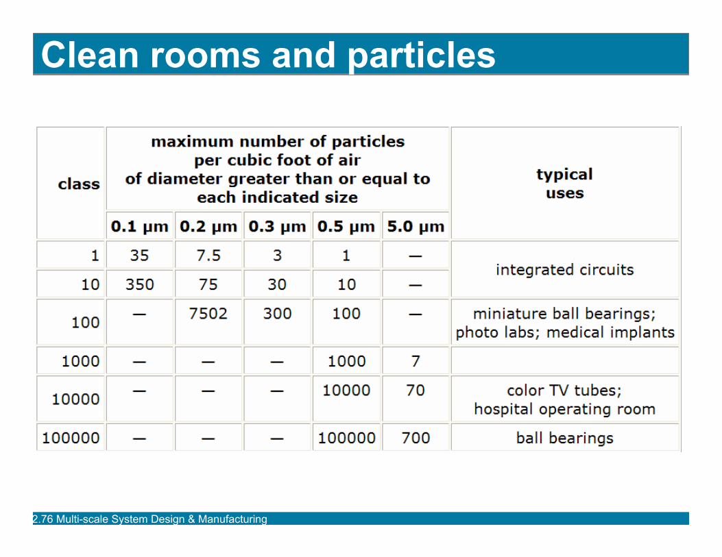
Clean rooms and particles
2.76 Multi-scale System Design & Manufacturing
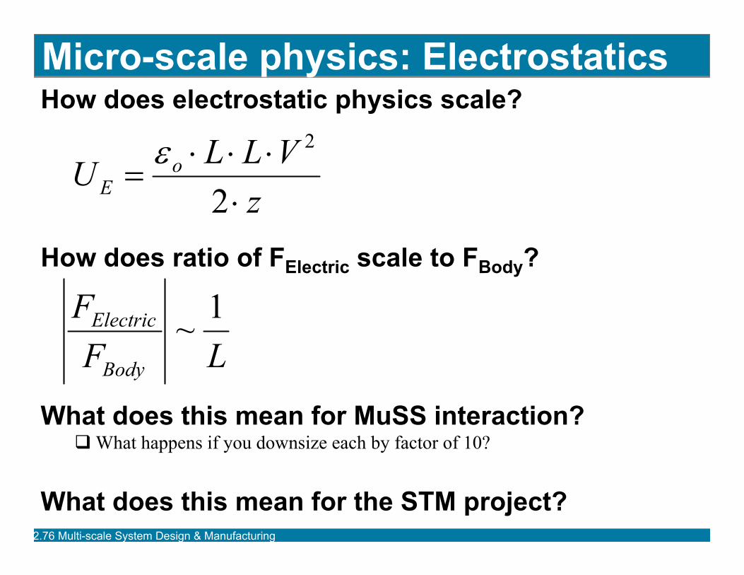
Micro-scale physics: ElectrostaticsHow does electrostatic physics scale?
How does ratio of FElectric scale to FBody?
What does this mean for MuSS interaction?What happens if you downsize each by factor of 10?
What does this mean for the STM project?
zVLLU o
E ⋅⋅⋅⋅
=2
2ε
LFF
Body
Electric 1~
2.76 Multi-scale System Design & Manufacturing
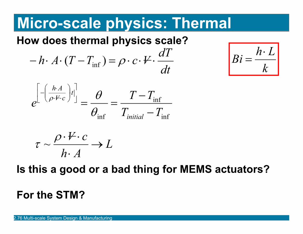
Micro-scale physics: ThermalHow does thermal physics scale?
Is this a good or a bad thing for MEMS actuators?
For the STM?
dtdTVcTTAh ⋅⋅⋅=−⋅⋅− ρ)( inf
inf
inf
inf TTTTe
initial
tcVAh
−−
==⎥⎦
⎤⎢⎣
⎡⋅⎟⎟⎠
⎞⎜⎜⎝
⎛⋅⋅
⋅−
θθρ
LAhcV→
⋅⋅⋅ρτ ~
kLhBi ⋅
=
2.76 Multi-scale System Design & Manufacturing
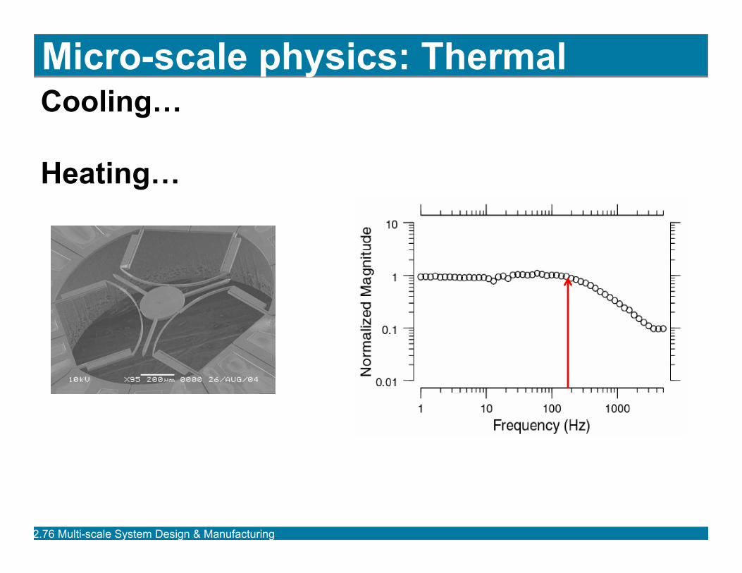
Micro-scale physics: ThermalCooling…
Heating…

2.76 Multi-scale System Design & Manufacturing
AssignmentWhat are the implications for rinsing
suspended MEMS devices clean of acids in distilled water? For example you might model a cantilever which of course has a finite stiffness…
Comment on humidity and MEMS devices
1 page maximum!!!
Email to course secretary by Wednesday 5pm.
Matweb.com