CONSTITUTIVE MODELING OF CREEP OF SINGLE … · I would also like to gratefully acknowledge Prof....
130
CONSTITUTIVE MODELING OF CREEP OF SINGLE CRYSTAL SUPERALLOYS A Dissertation by SHARAT CHAND PRASAD Submitted to the Office of Graduate Studies of Texas A&M University in partial fulfillment of the requirements for the degree of DOCTOR OF PHILOSOPHY August 2005 Major Subject: Mechanical Engineering
Transcript of CONSTITUTIVE MODELING OF CREEP OF SINGLE … · I would also like to gratefully acknowledge Prof....

CONSTITUTIVE MODELING OF CREEP OF SINGLE CRYSTAL
SUPERALLOYS
A Dissertation
by
SHARAT CHAND PRASAD
Submitted to the Office of Graduate Studies ofTexas A&M University
in partial fulfillment of the requirements for the degree of
DOCTOR OF PHILOSOPHY
August 2005
Major Subject: Mechanical Engineering

CONSTITUTIVE MODELING OF CREEP OF SINGLE CRYSTAL
SUPERALLOYS
A Dissertation
by
SHARAT CHAND PRASAD
Submitted to the Office of Graduate Studies ofTexas A&M University
in partial fulfillment of the requirements for the degree of
DOCTOR OF PHILOSOPHY
Approved by:
Chair of Committee, K. R. RajagopalCommittee Members, J. N. Reddy
Ibrahim KaramanJay R. Walton
Head of Department, Dennis O’Neal
August 2005
Major Subject: Mechanical Engineering

iii
ABSTRACT
Constitutive Modeling of Creep of Single Crystal Superalloys. (August 2005)
Sharat Chand Prasad, B.Tech., Indian Institute of Technology, Kanpur;
M.S., Texas A&M University
Chair of Advisory Committee: Dr. K. R. Rajagopal
In this work, a constitutive theory is developed, within the context of continuum
mechanics, to describe the creep deformation of single crystal superalloys. The con-
stitutive model that is developed here is based on the fact that as bodies deform
the stress free state that corresponds to the current configuration (referred to as the
“natural configuration”, i.e., the configuration that the body would attain on the
removal of the external stimuli) evolves. It is assumed that the material possesses an
infinity of natural (or stress-free) configurations, the underlying natural configuration
of the body changing during the deformation process, with the response of the body
being elastic from these evolving natural configurations. It is also assumed that the
evolution of the natural configurations is determined by the tendency of the body to
undergo a process that maximizes the rate of dissipation. Central to the theory is
the prescription of the forms for the stored energy and rate of dissipation functions.
The stored energy reflects the fact that the elastic response exhibits cubic symmetry.
Consistent with experiments, the elastic response from the natural configuration is
assumed to be linearly elastic and the model also takes into account the fact that
the symmetry of single crystals does not change with inelastic deformation. An ap-
propriate form for the inelastic stored energy (the energy that is ‘trapped’ within
dislocation networks) is also utilized based on simple ideas of dislocation motion. In
lieu of the absence of any experimental data to corroborate with, the form for the
inelastic stored energy is assumed to be isotropic. The rate of dissipation function is
iv
chosen to be anisotropic, in that it reflects invariance to transformations that belong
to the cubic symmetry group. The rate of dissipation is assumed to be proportional
to the density of mobile dislocations and another term that takes into account the
damage accumulation due to creep. The model developed herein is used to simulate
uniaxial creep of <001>, <111> and <011> oriented single crystal nickel based su-
peralloys for a range of temperatures. The predictions of the theory match well with
the available experimental data for CMSX-4. The constitutive model is also imple-
mented as a User Material (UMAT) in commercial finite element software ABAQUS
to enable the analysis of more general problems. The UMAT is validated for simple
problems and the numerical scheme based on an implicit backward difference formula
works well in that the results match closely with those obtained using a semi-inverse
approach.

v
To my mother, father and brother, Manish

vi
ACKNOWLEDGMENTS
I would like to express my sincere gratitude to Prof. K.R. Rajagopal for giving me this
excellent opportunity to work with him. During my four years of stay in the graduate
school, I have learnt a great deal from his vast knowledge in mechanics, mathematics
and life in general. His demand for perfection in everything has always inspired and
challenged me to put forth my best effort. Prof. Rajagopal’s lectures on continuum
mechanics and elasticity were outstanding and his unique style of teaching always
kept my enthusiasm sky high. His discourses on various aspects of mechanics both
during the group meetings and during our personal interactions have helped me think
critically. The freedom that he gave me in pursuing my ideas during the course of my
research work has helped me prepare mentally to work as an independent researcher.
I would also like to gratefully acknowledge Prof. J.N. Reddy’s support, encour-
agement and advice during the course of my research work. Prof. Reddy’s lectures
on non-linear finite element methods and composites inspired me a great deal about
the computational aspects of engineering problems. His course on non-linear finite
element method is one of the most challenging courses that I had during my stay
in the graduate school. Prof. Reddy’s well organized classes and assignments were
extremely helpful in gaining a strong foothold in computational mechanics.
I would like to thank Prof. Jay R. Walton for serving on my committee. Prof.
Walton’s classes on applied mathematics and mathematical foundations of continuum
mechanics helped me acquire the mathematical background needed for research work
in continuum mechanics. His well organized classes and challenging assignments
always fascinated me.
I would also like to thank Dr. Ibrahim Karaman for serving on my committee.
I also want to thank Dr. I. Joga Rao who was the co-principal investigator of

vii
the project I worked on. His advice and help on various issues during the research
work was very useful.
I would also take this opportunity to thank Dr. Luoyi Tao, Dr. J. Murali
Krishnan and Dr. Krishna Kannan for their support, encouragement and advice and
helping me out whenever I was stuck. My numerous discussions on various issues
related to my research work and mechanics in general with Dr. Krishna Kannan,
Dr. Saravanan Umakanthan, Dr. Anand Mohan, Dr. Pradeep Hariharkumar, Parag
Ravindran, and Shankar C. Subramanian have helped me think clearly and analyze
issues with a broader perspective.
I am also grateful for all the love, support and encouragement that I received
from my family. I am deeply indebted to my parents who have always encouraged
me to put my greatest effort into all my endeavors. They taught me the importance
of knowledge and learning and the merit of being a good human being. My parent’s
lessons in science and mathematics during my early school years through high school
inspired me to pursue a career in science and engineering. I am also grateful to my
brother, Manish, who has always inspired me by always setting a high standard and
leading by example and for telling me, no matter how well I do, that it is not good
enough.
Some of the results of the current work were obtained using the Supercomputing
facility at Texas A&M University. I wish to acknowledge their support. The financial
support provided by United States Department of Energy through Contract # DE-
FC26-01NT41344 is also gratefully acknowledged.

viii
TABLE OF CONTENTS
CHAPTER Page
I INTRODUCTION . . . . . . . . . . . . . . . . . . . . . . . . . . 1
A. Microstructure of superalloys . . . . . . . . . . . . . . . . . 4
B. Creep properties . . . . . . . . . . . . . . . . . . . . . . . . 8
C. Previous works on single crystals . . . . . . . . . . . . . . 11
D. Current models for creep and shortcomings . . . . . . . . . 13
E. Goals of the current work . . . . . . . . . . . . . . . . . . 15
F. Outline of the dissertation . . . . . . . . . . . . . . . . . . 16
G. Notations . . . . . . . . . . . . . . . . . . . . . . . . . . . 17
II PRELIMINARIES . . . . . . . . . . . . . . . . . . . . . . . . . . 18
A. Kinematics . . . . . . . . . . . . . . . . . . . . . . . . . . . 18
B. Kinetics . . . . . . . . . . . . . . . . . . . . . . . . . . . . 21
C. Balance laws . . . . . . . . . . . . . . . . . . . . . . . . . . 22
1. Balance of mass . . . . . . . . . . . . . . . . . . . . . 22
2. Balance of linear and angular momentum . . . . . . . 23
3. Balance of energy . . . . . . . . . . . . . . . . . . . . 23
D. Second law of thermodynamics . . . . . . . . . . . . . . . . 24
E. Material frame indifference . . . . . . . . . . . . . . . . . . 25
F. Theory of simple materials and single crystals . . . . . . . 26
G. The framework of multiple natural configurations . . . . . 29
III A CONTINUUM MODEL FOR CREEP OF SUPERALLOYS . 31
A. Development of constitutive model . . . . . . . . . . . . . 31
B. Specific constitutive relations . . . . . . . . . . . . . . . . 33
1. The Helmholtz potential ψ . . . . . . . . . . . . . . . 33
2. Inelastic part of the stored energy ψ . . . . . . . . . . 33
3. Rate of dissipation . . . . . . . . . . . . . . . . . . . . 36
4. Instantaneous rate of energy storage, R . . . . . . . . 39
IV CREEP OF SUPERALLOYS LOADED ALONG THE <001>,
<111> AND <011> ORIENTATIONS . . . . . . . . . . . . . . 41
A. Problem formulation for loading along the <001>, <111>
and <011> orientations . . . . . . . . . . . . . . . . . . . 41

ix
CHAPTER Page
B. Results for loading along the <001> orientation . . . . . . 44
C. Results for loading along the <001>, <111> and <011>
orientations . . . . . . . . . . . . . . . . . . . . . . . . . . 59
V IMPLEMENTATION IN FINITE ELEMENT SOFTWARE
ABAQUS . . . . . . . . . . . . . . . . . . . . . . . . . . . . . . 74
A. Numerical scheme . . . . . . . . . . . . . . . . . . . . . . . 75
1. UMAT for creep along the <001> orientation . . . . . 76
2. Validation of UMAT for creep along the <001>
orientation . . . . . . . . . . . . . . . . . . . . . . . . 79
VI A THERMOMECHANICAL MODEL FOR THE CREEP
OF SUPERALLOYS . . . . . . . . . . . . . . . . . . . . . . . . 92
A. Development of non-isothermal model . . . . . . . . . . . . 92
VII CONCLUSIONS . . . . . . . . . . . . . . . . . . . . . . . . . . . 97
A. Summary . . . . . . . . . . . . . . . . . . . . . . . . . . . 97
B. Recommendations for future work . . . . . . . . . . . . . . 99
REFERENCES . . . . . . . . . . . . . . . . . . . . . . . . . . . . . . . . . . . 102
VITA . . . . . . . . . . . . . . . . . . . . . . . . . . . . . . . . . . . . . . . . 115

x
LIST OF TABLES
TABLE Page
I Some applications of superalloys [17, 18]. . . . . . . . . . . . . . . . . 2
II Generations of single crystal nickel based superalloys and their
composition [18]. . . . . . . . . . . . . . . . . . . . . . . . . . . . . . 3
III Role of alloying elements in superalloys [17, 18]. . . . . . . . . . . . . 4
IV Various phases present in single crystal nickel based superalloys
[17, 18]. . . . . . . . . . . . . . . . . . . . . . . . . . . . . . . . . . . 5
V Parameters characterizing the elastic response of CMSX-4 at var-
ious temperatures [88]. . . . . . . . . . . . . . . . . . . . . . . . . . . 44
VI Material parameters for CMSX-4 at various temperatures for load-
ing along the <001> orientation. . . . . . . . . . . . . . . . . . . . . 45
VII Material parameters for CMSX-4 at various temperatures. . . . . . . 61
VIII Schematic of the user subroutine UMAT in ABAQUS/STANDARD. 74
xi
LIST OF FIGURES
FIGURE Page
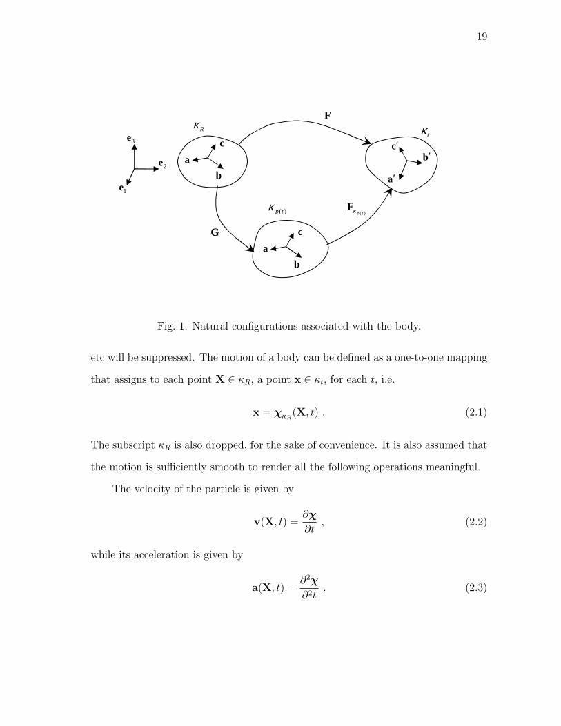
1 Natural configurations associated with the body. . . . . . . . . . . . 19
2 Noll’s rule for simple materials. . . . . . . . . . . . . . . . . . . . . . 28
3 Shearing of the lattice of a single crystal. . . . . . . . . . . . . . . . . 29
4 Creep of a specimen loaded along the direction <l, m, n> under
constant load. . . . . . . . . . . . . . . . . . . . . . . . . . . . . . . . 41
5 Strain vs. time for CMSX-4 for loading along the <001> orien-
tation, θ = 750 oC: Comparison of the predictions of the model
with experimental results of Svoboda and Lucas [90] and Hender-
son and Lindblom [32]. . . . . . . . . . . . . . . . . . . . . . . . . . . 47
6 Strain vs. time for CMSX-4 for loading along the <001> orien-
tation, θ = 982 oC: Comparison of the predictions of the model
with experimental results of Svoboda and Lucas [90] and Hender-
son and Lindblom [32]. . . . . . . . . . . . . . . . . . . . . . . . . . . 48
7 Strain vs. time for CMSX-4 for loading along the <001> orien-
tation, θ = 1000 oC: Comparison of the predictions of the model
with experimental results of Svoboda and Lucas [90] and Hender-
son and Lindblom [32]. . . . . . . . . . . . . . . . . . . . . . . . . . . 49
8 Inelastic stored energy vs. inelastic strain pathlength for CMSX-4
for loading along the <001> orientation, θ = 750 oC: Predictions
of the model. . . . . . . . . . . . . . . . . . . . . . . . . . . . . . . . 50
9 Inelastic stored energy vs. inelastic strain pathlength for CMSX-4
for loading along the <001> orientation, θ = 982 oC: Predictions
of the model. . . . . . . . . . . . . . . . . . . . . . . . . . . . . . . . 51
10 Inelastic stored energy vs. inelastic strain pathlength for CMSX-4
for loading along the <001> orientation, θ = 1000 oC: Predictions
of the model. . . . . . . . . . . . . . . . . . . . . . . . . . . . . . . . 52
xii
FIGURE Page
11 Third component of backstress vs. inelastic strain pathlength for
CMSX-4 for loading along the <001> orientation, θ = 750 oC:
Predictions of the model. . . . . . . . . . . . . . . . . . . . . . . . . 53
12 Third component of backstress vs. inelastic strain pathlength for
CMSX-4 for loading along the <001> orientation, θ = 982 oC:
Predictions of the model. . . . . . . . . . . . . . . . . . . . . . . . . 54
13 Third component of backstress vs. inelastic strain pathlength for
CMSX-4 for loading along the <001> orientation, θ = 1000 oC:
Predictions of the model. . . . . . . . . . . . . . . . . . . . . . . . . 55
14 Instantaneous rate of energy storage vs. inelastic strain path-
length for CMSX-4 for loading along the <001> orientation, θ =
750 oC: Predictions of the model. . . . . . . . . . . . . . . . . . . . . 56
15 Instantaneous rate of energy storage vs. inelastic strain path-
length for CMSX-4 for loading along the <001> orientation, θ =
982 oC: Predictions of the model. . . . . . . . . . . . . . . . . . . . . 57
16 Instantaneous rate of energy storage vs. inelastic strain path-
length for CMSX-4 for loading along the <001> orientation, θ =
1000 oC: Predictions of the model. . . . . . . . . . . . . . . . . . . . 58
17 Strain vs. time for CMSX-4 for loading along the <001> orien-
tation, θ = 800 oC: Comparison of the predictions of the model
with experimental results of Schubert et al., [87]. . . . . . . . . . . . 62
18 Strain vs. time for CMSX-4 for loading along the <111> orien-
tation, θ = 800 oC: Comparison of the predictions of the model
with experimental results of Schubert et al., [87]. . . . . . . . . . . . 63
19 Strain vs. time for CMSX-4 for loading along the <011> orien-
tation, θ = 800 oC: Predictions of the model. . . . . . . . . . . . . . . 64
20 Strain vs. time for CMSX-4 for loading along the <001> orien-
tation, θ = 950 oC: Comparison of the predictions of the model
with experimental results of MacLachlan et al., [45]. . . . . . . . . . 65

xiii
FIGURE Page
21 Strain vs. time for CMSX-4 for loading along the <111> orien-
tation, θ = 950 oC: Comparison of the predictions of the model
with experimental results of MacLachlan et al., [45]. . . . . . . . . . 66
22 Strain vs. time for CMSX-4 for loading along the <011> orien-
tation, θ = 950 oC: Comparison of the predictions of the model
with experimental results of MacLachlan et al., [45]. . . . . . . . . . 67
23 Inelastic stored energy vs. inelastic strain pathlength for CMSX-4
, θ = 800 oC: Predictions of the model. . . . . . . . . . . . . . . . . . 68
24 Inelastic stored energy vs. inelastic strain pathlength for CMSX-4
, θ = 950 oC: Predictions of the model. . . . . . . . . . . . . . . . . . 69
25 Third component of backstress vs. inelastic strain pathlength for
CMSX-4 , θ = 800 oC: Predictions of the model. . . . . . . . . . . . . 70
26 Third component of backstress vs. inelastic strain pathlength for
CMSX-4 , θ = 950 oC: Predictions of the model. . . . . . . . . . . . . 71
27 Instantaneous rate of energy storage vs. inelastic strain path-
length for CMSX-4 , θ = 800 oC: Predictions of the model. . . . . . . 72
28 Instantaneous rate of energy storage vs. inelastic strain path-
length for CMSX-4 , θ = 950 oC: Predictions of the model. . . . . . . 73
29 Strain vs. time for CMSX-4 for loading along the <001> orien-
tation, θ = 750 oC: Comparison of the results obtained from User
Material in ABAQUS with results obtained in MATLAB and ex-
perimental results of Svoboda and Lucas [90] and Henderson and
Lindblom [32]. . . . . . . . . . . . . . . . . . . . . . . . . . . . . . . 80
30 Strain vs. time for CMSX-4 for loading along the <001> orien-
tation, θ = 982 oC: Comparison of the results obtained from User
Material in ABAQUS with results obtained in MATLAB and ex-
perimental results of Svoboda and Lucas [90] and Henderson and
Lindblom [32]. . . . . . . . . . . . . . . . . . . . . . . . . . . . . . . 81

xiv
FIGURE Page
31 Strain vs. time for CMSX-4 for loading along the <001> orienta-
tion, θ = 1000 oC: Comparison of the results obtained from User
Material in ABAQUS with results obtained in MATLAB and ex-
perimental results of Svoboda and Lucas [90] and Henderson and
Lindblom [32]. . . . . . . . . . . . . . . . . . . . . . . . . . . . . . . 82
32 Inelastic stored energy vs. inelastic strain pathlength for CMSX-4
for loading along the <001> orientation, θ = 750 oC: Compari-
son of the results obtained from User Material in ABAQUS with
results obtained in MATLAB. . . . . . . . . . . . . . . . . . . . . . . 83
33 Inelastic stored energy vs. inelastic strain pathlength for CMSX-4
for loading along the <001> orientation, θ = 982 oC: Compari-
son of the results obtained from User Material in ABAQUS with
results obtained in MATLAB. . . . . . . . . . . . . . . . . . . . . . . 84
34 Inelastic stored energy vs. inelastic strain pathlength for CMSX-4
for loading along the <001> orientation, θ = 1000 oC: Compari-
son of the results obtained from User Material in ABAQUS with
results obtained in MATLAB. . . . . . . . . . . . . . . . . . . . . . . 85
35 Third component of backstress vs. inelastic strain pathlength for
CMSX-4, θ = 750 oC: Comparison of the results obtained from
User Material in ABAQUS with results obtained in MATLAB. . . . . 86
36 Third component of backstress vs. inelastic strain pathlength for
CMSX-4, θ = 982 oC: Comparison of the results obtained from
User Material in ABAQUS with results obtained in MATLAB. . . . . 87
37 Third component of backstress vs. inelastic strain pathlength for
CMSX-4, θ = 1000 oC: Comparison of the results obtained from
User Material in ABAQUS with results obtained in MATLAB. . . . . 88
38 Instantaneous rate of energy storage vs. inelastic strain path-
length for CMSX-4 for loading along the <001> orientation, θ =
750 oC: Comparison of the results obtained from User Material in
ABAQUS with results obtained in MATLAB. . . . . . . . . . . . . . 89

xv
FIGURE Page
39 Instantaneous rate of energy storage vs. inelastic strain path-
length for CMSX-4 for loading along the <001> orientation, θ =
982 oC: Comparison of the results obtained from User Material in
ABAQUS with results obtained in MATLAB. . . . . . . . . . . . . . 90
40 Instantaneous rate of energy storage vs. inelastic strain path-
length for CMSX-4 for loading along the <001> orientation, θ =
1000 oC: Comparison of the results obtained from User Material
in ABAQUS with results obtained in MATLAB. . . . . . . . . . . . . 91

1
CHAPTER I
INTRODUCTION
The demand to increase the efficiency of gas turbines used in power generation and
aircraft applications has fueled research to develop advanced materials for gas turbine
blades that can withstand high temperatures. In fact, higher efficiencies of such
engines are possible if turbine blades can be designed to withstand inlet temperature
of the order of 1500 oC or more. At such high temperatures, it is critical to use
materials that have excellent creep capabilities.
The term “Superalloys” describe a group of alloys developed for applications that
require high performance at elevated temperatures. Superalloys have a load bearing
capacity up to 0.9 times their melting temperature. They retain their strength even
after long exposure time at high temperatures and they have good low temperature
ductility as well. There are three categories of superalloys that have been developed:
1. Nickel based superalloys
2. Iron-nickel based superalloys
3. Cobalt based superalloys
Superalloys are available as
1. Polycrystalline superalloys
2. Columnar grain directionally solidified superalloys
3. Single crystal superalloys
The journal model is IEEE Transactions on Automatic Control.

2
Table I. Some applications of superalloys [17, 18].
Aircraft/industrial gas turbines
Blades, Vanes, Disks, Bolts, Shafts, Cases, Combustors,
Afterburners, Thrust reversers
Steam turbines
Blades, Bolts, Reheaters
Automotive components
Turbochargers, Exhaust valves
Nuclear power systems
Control-rod drive mechanisms, Valve stems, Springs, Ducting
Space vehicles
Aerodynamically heated skins, Rocket engine parts
Medical components
Prosthetic devices
Metal processing
Hot work tools and dies
Because of their excellent thermal, fatigue and creep properties, superalloys are
used in numerous applications. Table I lists some of the applications of superalloys.
Single crystal superalloys have the highest temperature capacity and hence they
are used in the hottest sections of gas turbine engines. The most important of these
alloys are the ones which are based on nickel and modeling the creep behavior of such
alloys is the primary goal of current work. Henceforth focus will be laid on describing
the behavior of single crystal nickel based superalloys.
Single crystal superalloys have superior thermal, fatigue and creep properties
amongst the class of superalloys because grain boundaries have been eliminated. A

3
Table II. Generations of single crystal nickel based superalloys and their composition
[18].
Alloy Ni Cr Co Mo W Al Ti Ta Re Nb V Hf
First generation
PWA 1480 62.5 10 5 4 5 1.5 12
Rene N4 62.6 9 8 2 6 3.7 4.2 4 0.5
CMSX-2 66.6 8 4.6 0.6 7.9 5.6 0.9 5.8
SRR 99 66.5 8.5 5 9.5 5.5 2.2 2.8
Second generation
PWA 1484 59.4 5 10 2 6 5.6 9 3
Rene N5 61.8 7 8 2 5 6.2 7 3 0.2
CMSX 4 61.8 6.5 9 0.6 6 5.6 1 6.5 3 0.1
CMSX 6 70.4 10 5 3 4.8 4.7 2 0.1
Third generation
CMSX-10 69.6 2 3 0.4 5 5.7 0.2 8 6 0.1 0.03
Rene N6 57.4 4.2 12.5 1.4 6 5.75 0 7.2 5.4 0 0 0.15
whole generation of single crystal nickel based superalloys have been developed over
the last few decades with significant improvement in the operating temperature. Table
II lists the generations of single crystal nickel based superalloys developed over last
few decades.
The second and third generation of superalloys are characterized by increasing
concentration of Rhenium which improves creep and fatigue resistance. Fourth gener-
ation superalloys with Ruthenium are also being developed with further enhancement
in high temperature creep resistance.
Table II also lists the alloying elements that are added in single crystal nickel

4
Table III. Role of alloying elements in superalloys [17, 18].
Effects Alloying elements
Solid solution strengthening Co, Cr, Mo, W, Ta, Re
Formation of γ′ (Ni3Al, Ni3Ti), the prin-
ciple strengthening phase
Al, Ti
Raises solvus temperature of γ′ Co
Oxidation resistance Al, Cr
Formation of hardening phase γ′′ (Ni3Nb) Nb
Sulfidation resistance Cr, Co
Retards γ′ rafting Re
Formation of topologically closed packed
(TCP) phases1
Co, Mo, W, Re, Cr
based superalloys. Various alloying additions alter the thermal and mechanical be-
havior of superalloys. Since single crystal nickel based superalloys are multi-phase
alloys, the presence of various alloying additions significantly alter the microstruc-
ture. Table III lists the role various alloying elements play in a modern single crystal
nickel based superalloy.
A. Microstructure of superalloys
A typical modern superalloy (eg. CMSX-4) for turbine blades is a single crystal,
which contains particles, based on the ordered γ′ L12 structure, lying in a matrix
based on a disordered face-centered cubic Ni3Al. The γ′ phase forms remarkably
regular cubes packed in a rather regular cubic array and it occupies 65− 70% of the
1TCP phases are brittle phases which are detrimental to the mechanical propertiesof superalloys.

5
volume. The shape, size and arrangement of γ′ precipitates in the matrix depend on
the kind of heat treatment the alloy is subject to, and it can significantly affect the
creep strength [8].
Table IV. Various phases present in single crystal nickel based superalloys [17, 18].
Phase Crystal struc-
ture
Formula Effects
γ′ Face centered
cubic
Ni3(Al, T i) Principal strengthening phase, vol-
ume fraction could be as high as 70
%
η Hexagonal
closed packed
Ni3Ti Causes some amount of hardening
γ′′ Body cen-
tered tetrago-
nal
Ni3Nb Principal hardening phase in cer-
tain alloys, careful precipitation is
needed to avoid formation of δ
phase
Ni3Nb (δ) Orthorhombic Ni3Nb detrimental to properties when
present in large amount
µ2 Rhombohedral Co2W6 TCP phase, detrimental to mechan-
ical properties
The two-phase structure of a superalloy contributes essentially to its excellent
creep strength at high temperatures, the phase boundaries providing obstacles to
dislocation motion. The volume fraction of the γ′ phase is an important factor in
optimizing superalloy composition to get the best creep strength. Usually a maximum
2Laves and σ are other TCP phases which appear in iron-nickel and cobalt basedsuperalloys.

6
in the creep strength is reached between 70 and 80% volume fraction of γ′ phase with
further increase leading to a significant drop in strength (see [18]).
Although γ′ is the principle hardening phase in single crystal nickel based super-
alloys, various alloying elements that are added during the formation of superalloys
cause numerous other phases to precipitate. Table IV lists some of the phases that
are present in single crystal nickel based superalloys. Addition of carbon and boron in
polycrystalline superalloys (all three groups) lead to formation of carbide and boride
phases which cause grain boundary strengthening. They also tie up with certain
elements which may cause phase instability otherwise.
It has been observed by Pollock and Argon [64] that in the primary stage of
creep in modern superalloys, and during most of the secondary creep, plastic defor-
mation is confined to the γ channels. The γ′ particles act as impenetrable obstacles.
The γ′ phase has another very remarkable property. Whereas most metals and al-
loys, including the γ matrix, have flow stresses that decreases steadily with increasing
temperature, alloys related to Ni3Al, and many other alloys with the L12 structure,
show flow stresses that can increase by a factor of 5 as the temperature increases from
room temperature to about 650 oC [53]. The high strength of γ′ is especially valuable
at high temperatures.
The lattice parameters of the γ matrix and the γ′ precipitate are very similar, but
not identical. The creep deformed microstructure and many mechanical properties
depend on the lattice misfit (defined as δ = 2(aγ′ − aγ)/(aγ′ + aγ), where aγ′ and
aγ are lattice parameters of γ′ and γ phases respectively). The presence of various
alloying elements strongly affects the value of the misfit. The misfit could be positive
or negative depending on the particular composition of the superalloy. Moreover, the
misfit changes with the kind of heat treatment, the alloy is subject to and it also
varies with the temperature [58, 6]. The sign of the misfit plays an important role in

7
the evolution of microstructure as the material creeps.
One of the most important microstructural properties of nickel based superalloys
containing high volume fraction of γ′ precipitates is the ability of cubic γ′ phase to
transform into flat plates (“rafts”) under the influence of stress and temperature.
This process is known as “Rafting”. The rafting behavior of γ′ phase has been
subject to numerous investigations since it was first observed in 1960s ([100]). This
directional coarsening is especially important in nickel based superalloys because the
morphological changes in the two phase microstructure alters the creep resistance
of the material in the stress and temperature range where these alloys are used in
applications such as turbine blades. Two types of rafting behavior in <001> oriented
nickel based single crystals have been identified ([96, 95]).
1. Type N - Rafts develop transverse to the direction of the externally applied
load;
2. Type P - Rafts develop parallel to the direction of the externally applied load.
Type N behavior is usually associated with negative misfit alloys stressed in ten-
sion, or positive misfit alloys stressed in compression. Conversely, type P behavior
is associated with positive misfit alloys stressed in tension, and negative misfit alloys
stressed in compression, i.e., the direction of rafting depends upon the direction of
loading and the sign of lattice misfit. The differences in the microstructural evolu-
tion associated with a change from positive to negative misfit are an indication that
the rafting is primarily dominated by internal stresses developed due to the misfit.
In fact, the γ − γ′ interface plays an important role in creep property of superalloys
[16, 55]. The evolution of rafts with creep depends on the applied stress and operating
temperature. The kinetics of rafting and its dependence on various factors is still not
fully understood at this point. Matan et al. [48] conducted experiments on CMSX-4

8
at 950 oC to determine the influence of applied stress. They observed that specimens
which have attained a critical value of plastic strain continue to raft further even if
the applied stress is removed, while rafts in specimens having strains lesser than the
critical value cease to develop further. At temperatures beyond 950 oC, experiments
conducted by Reed et al. [84] suggest that rafting is complete during very early stages
of creep. Most of the experimental observations on rafting are available for loading
along <001> orientation. The manner in which rafting takes place for loading away
from <001> orientation is still not clear. Apart from this, the kinetics of rafting
behavior for complex loading conditions, a scenario quite common in actual practice,
is still not understood.
B. Creep properties
The creep behavior of single crystal superalloys is highly anisotropic. The inherent
crystallography of single crystals leads to orientation dependent creep behavior. From
a design point of view, it is imperative to use an orientation, which utilizes maximum
strength of the superalloy. In fact it is known that the creep strength of a modern
single crystal superalloy along the <001> orientation , which is also the preferred
grain growth direction is favorable compared to the <011> or <111> orientations.
There have been numerous experimental investigations into the creep behavior and
the related microstructural aspects of the <001> oriented single crystal nickel based
superalloys. Apart from this, experiments have also focussed on characterizing the
behavior of single crystal turbine blades with centrifugal loading away from the ex-
act <001> orientation. Such situations are common in actual practice where mis-
alignment of up to 15o [49] could occur due to variety of reasons.
A number of studies have been devoted to studying the creep performance
9
of <001> oriented superalloy single crystals. At lower temperatures, particularly
in the vicinity of 750 oC, a considerable amount of primary creep can occur (see [42]
and [20]). At temperatures between 850 oC and 1000 oC, loading along <001> yields
a creep strain rate which increases monotonically with creep strain (i.e., tertiary
creep is dominant), there being no evidence of a steady state regime (See [8], [55]
and [86]). At temperatures beyond 1000 oC, Reed et al. [84] reported that rafting
of γ′ phase occurs very rapidly and is complete in the very initial stages of creep
deformation. After this stage, strain rate decreases with increasing strain for a con-
siderable amount of time. Reed et al. [84] concluded that this strain hardening effect
arises as a consequence of rafting of γ′ phase. The strain rate in this temperature
range keeps decreasing with increasing strain until a critical strain is reached. After
the critical strain is reached, the creep strain rate increase sharply with strain with
failure occurring eventually. Moreover, this critical strain was found to be essentially
constant in the temperature range of 1050− 1200 oC. Reed et al. [84] observed that
the rapid increase in the creep strain in the later stages of creep is associated with
highly localized deformations in the vicinity of the fracture surface. Furthermore, this
creep deformation is associated with creep cavitation occurring at, or in the vicinity
of casting porosity and topologically closed packed (TCP) phases.
As pointed out earlier, the inherent crystallography of single crystals leads to
orientation dependent creep behavior. The degree of anisotropy is strongly influ-
enced by the temperature (around 750-850 oC) and it is also known that at higher
temperatures, the orientation dependence of creep behavior is less strong. Several
studies have been devoted to study the effect of orientation on creep behavior of
single crystal superalloys and identify the slip systems responsible for the observed
deformation behavior. Experiments carried out by Kear and Piearcey [37] on first
generation single crystal nickel based superalloy MAR-M200 revealed that creep re-
10
sistance close to the <001> and <111> orientations is substantially better than that
close to the <011> orientation in the temperature range 760-871 oC. They also found
that orientation has much less influence on creep life at 982 oC. It was also observed
that at 760 oC, <001> orientation has the best creep life , however at temperatures
872 and 982 oC, <111> orientation displayed the best creep life. Significant amount
of primary creep was observed close to the <001> orientation at 760 oC, however
primary creep was absent for the <011> and <111> orientations. At temperatures
beyond 760 oC, tertiary creep was dominant in all the orientations studied. Another
experimental study on creep of MAR-M200 at 760 oC was performed by Leverant and
Kear [41], wherein they studied the creep behavior of specimens oriented within 18o
of <001> orientation. They observed primary, secondary and tertiary creep regimes
for all the orientations and noted that the primary and steady state creep rates in-
crease in the following order: <001>, <001>/<011> boundary, orientations between
<001>/<011> and <001>/<111> boundaries, <001>/<111> boundary. A similar
study performed by MacKay and Maier [43] on another first generation single crys-
tal nickel based superalloy MAR-M247 at temperature 774 oC showed that crystals
having orientations within 25o of the <001> orientation exhibited significantly longer
creep lives when their orientations were closer to the <001>/<011> boundary of the
stereographic triangle than to the <001>/< 111> boundary. These observations were
in accordance with the results for the creep of MAR-M200 ([37, 41]), the only dif-
ference being that MAR-M247 showed best creep life close to the <111> orientation
whereas MAR-M200 showed best creep life close to the <001> orientation. Caron et
al. [9] studied the effect of orientation on creep lives of first generation single crystal
nickel based superalloy CMSX-2 at 760 oC and 750 MPa. Their experiments showed
that the best creep life occurs close to the <001> orientation, however unlike the re-
sults for MAR-M200 and MAR-M247 [37, 41, 43], CMSX-2 exhibited very poor creep

11
life close to the <111> orientation. Moreover, orientations away from the <001>
orientation (say by 20o) did not cause significant reduction in creep life as was the
case for MAR-M200 and MAR-M247 [37, 41, 43].
The effect of orientation on creep behavior of second generation single crys-
tal nickel based superalloy CMSX-4 was studied by Matan et al. [47]. They stud-
ied the creep behavior for small misorientations away from the <001> orientation.
Their investigation showed that at 750 oC, significant amount of primary creep takes
place, the extent of which depends strongly upon small misorientations away from
the <001>/<011> boundary of the stereographic triangle. At 950 oC, tertiary creep
is dominant with very little primary creep. They also observed that orientation de-
pendence is less strong at 950 oC. Recent creep tests carried out by Gunturi et al.
[30] on CMSX-4 at 750 oC in crystallographic orientations distant from the <001>
orientation showed that orientations distant from the <001>/<111> boundary had
relatively lower creep lives while orientations closer to the <001>/<111> boundary
had longer creep life.
C. Previous works on single crystals
Several models have been proposed to describe the response of single crystals. The
notion of Bravais lattice has been associated with the structure of single crystals at
the atomic level to model its behavior. The single crystals are not free of imper-
fections in that they have dislocations and inclusions which are responsible for the
permanent inelastic deformation of single crystals. In polycrystals, the presence of
grain boundaries complicate the material behavior significantly.
There are several studies on the kinematical aspects of crystals, under the as-
sumption of uniformly distributed dislocations (see Bilby [4], Eshelby [22], Kondo [38],

12
Kroner [39] and Nabarro [52]). A dynamical theory based for single crystals based on
the notion of a Cosserat continuum via the introduction of directors was established
by Naghdi and Srinivasa [57]. The theory based on the notion of directors has several
inherent difficulties such as introduction of new balance laws containing terms which
are not physically motivated. Moreover there are associated difficulties with regard
to specifying boundary conditions for quantities such as directors. Naghdi and Srini-
vasa [56] have also introduced a measure of the influence of dislocations on the plastic
deformation of single crystals through the curl of the plastic deformation gradient.
Early experiments on single crystals were carried out by Ewing and Resen-
hain [23], Taylor and Elam [92, 93, 94], Piercy et al. [61], and Kocks [62]. Piercy
et al. [61] and Kocks [62] studied multiple slips in single crystals. Various mecha-
nisms have been proposed to explain the response of single crystals and a discussion
on these can be found in papers by Asaro [1], Havner [31], Taylor [91] and Van
Buereu [98], .
The most important issue to recognize, concerning the modeling of a single crystal
is that it is not a simple material in the sense of Noll [60] (see also Truesdell and
Noll [97]), that is the stress in the material can not be purely determined by the
history of the deformation gradient. Several methods have been proposed to capture
this non-simple behavior of the body (for example, the theory based on directors)
but they are fraught with difficulties. One of the goals of the current work is to
understand why the theory of simple materials fail for single crystals and to develop
a rigorous approach to model such non-simple materials.

13
D. Current models for creep and shortcomings
There have been several attempts to model the creep behavior of single crystal su-
peralloys. Phenomenological models have been developed both to describe the creep
deformation of <001> oriented single crystals and to describe the orientation de-
pendence of creep behavior. Dyson and Mclean [20] observed that the tertiary creep
rate in most engineering materials including conventional nickel based superalloys
increases monotonically with accumulated plastic strain. They concluded that strain
softening is caused by active damage mechanisms (cavitation and development of
cracks on the surface) and accumulation of dislocations. They excluded the possibil-
ity of γ′ phase coarsening causing the strain softening as was thought earlier. They
also presented an empirical model wherein the strain rate is determined by inelastic
strain rather than time. Following their observations, several empirical models for
creep in superalloys have been proposed that take into account the kinetics of the
dislocation motion [19]. The models developed in [20] and [19] are isotropic mod-
els and hence cannot capture orientation dependent creep behavior. An extension
of the isotropic model to capture the anisotropic creep behavior was developed by
Ghosh and Mclean [27] and Ghosh et al. [26]. Since the level of primary creep ob-
served in most single crystal superalloys is small, they restricted their extension of
anisotropy to the analysis of tertiary creep only and not to the primary creep. Their
model accounted for tertiary creep based on the accumulation of mobile dislocations
with plastic strain. Reed et al. [84] extended the model developed by Ghosh and
co-workers to include the effect of rafting at high temperature.
Several other models for creep of superalloys have been proposed based on the
framework of continuum damage mechanics and single crystal plasticity. Bertram
and Olschewski [2] proposed an anisotropic constitutive model for describing creep

14
behavior of single crystal superalloys. They constructed a three-dimensional model
by a projection technique which is essentially a generalization of the four-parameter
Burgers model. Their model was restricted to the undamaged material behavior of the
primary and secondary creep phase. Qi and Bertram [66] extended the model using
the theory of continuum damage mechanics to incorporate the damage induced in the
material through the introduction of a fourth order tensor that assesses damage.
Recently Maclachlan and Knowles [44] have proposed a model based on single
crystal plasticity wherein they incorporate the damage induced due to creep through
a fourth order damage operator.
Most of the models for creep of single crystal superalloys fail to take into account
the symmetry of single crystals and the fact that the symmetry does not change as
the single crystal undergoes inelastic deformation. Apart from this, most of these
models are empirical in nature and lacked a three dimensional framework. These
models also lack thermodynamical underpinnings. Although models based on single
crystal plasticity are three dimensional and they incorporate the symmetry of single
crystals, such models require extensive details of slip systems which are operating.
Also, the model requires information about self and latent hardening of slip systems
that are active which lead to a overwhelming number of material parameters (The
model developed by Maclachlan and Knowles [44] has 42 material parameters).
The effect of high temperature rafting on creep was incorporated in models de-
veloped by Reed et al. [84] and Maclachlan and Knowles [44] who used a dislocation
hardening mechanism first proposed by Gilman [28]. Apart from including the effect
of rafting on creep in a macroscopic way, there have been several works devoted to
describe the kinetics of the rafting behavior itself but most of them are limited to
the elastic regime (see for example [63, 34, 35, 24, 25, 15, 54]). Such approaches are
fraught with difficulties as the elastic regime is very difficult to detect in modern su-

15
peralloys and rafting is always associated with significant amount of inelastic strain.
Such a drawback was emphasized by the work of Carry and Strudel [10, 11], Ignat
and co-workers [33, 7] and others where it was shown that interaction of dislocations
created during creep deformation with γ/γ′ interface play an important role in mor-
phological changes of precipitates. The models developed by Socrate and Parks [89]
and Veron et al. [99] attempted to account for the inelastic strain, but their work
was empirical in nature, lacked a 3D framework and was within the purview of small
strain theory.
E. Goals of the current work
In this work, the aim is to develop a constitutive theory within the context of contin-
uum mechanics, to predict the creep deformation of single crystal superalloys. The
goal of such continuum theories is to describe the macroscopic behavior of a material
without explicitly going into the complex details at the microscopic level, while at the
same time taking cognizance of the microstructure , albeit in a homogenized sense.
The constitutive model is within a thermodynamic setting and it exploits the
fact that the configuration that the body would attain on the removal of external
stimuli, referred to as “natural configuration”, evolves, with the response of the body
being non-dissipative (in more general situations non entropy producing) from these
evolving “natural configurations”. The evolution of these natural configurations is
determined by the tendency of the body to undergo a process that maximizes the
rate of dissipation.
As mentioned before, it is important to recognize that single crystals can not
be modeled by theory of simple materials. The lattice structure and the material
symmetry remains the same when a single crystal is subject to inelastic deformation.
16
This experimental fact was recognized by the seminal work of Taylor and Elam [92] in
as early as 1923. The current work aims to take cognizance of this essential empirical
fact and develop a constitutive theory that complies with this observation.
Another goal of the current work is to evaluate the theories based on single
crystal plasticity which explicitly take into account elaborate details of the motion
of dislocations on various slip systems and model the self and latent hardening of
these systems during the inelastic deformation process. Such an elaborate detail is
not needed to model the inelastic behavior of single crystals and a phenomenological
continuum mechanics based model which take cognizance of the microstructure in a
homogenized sense will suffice. As pointed out earlier, one of the shortcomings of
incorporating elaborate details regarding motion of dislocations on slip systems and
the hardening of slip systems is that one ends up with an overwhelming number of
material parameters.
F. Outline of the dissertation
The dissertation is organized as follows. In Chapter II, the preliminaries that form
the backbone of the current work is discussed. The kinematics, kinetics, balance
laws in continuum mechanics, second law of thermodynamics and the notion of frame
invariance is discussed. The theory of simple materials and why it can not be used
for modeling the response of single crystals and how the current framework is robust
enough to fill this lacunae are also discussed. In chapter III, an isothermal constitu-
tive model for high temperature creep of single crystal superalloys is developed. In
Chapter IV, the specific problem of creep deformation of single crystal superalloys for
loading along the <001>, <111> and <011> orientations is solved and the results
are presented. Chapter V deals with incorporating the constitutive model in finite

17
element software ABAQUS as a User Material (UMAT) to enable its use for solving
more general problems. A comparison between the results obtained using ABAQUS
and those obtained using a semi-inverse method is made. In Chapter VI, a thermo-
mechanical model for describing the creep of single crystal superalloys is developed.
The summary of the dissertation and recommendations for future work is presented
in Chapter VII.
G. Notations
The notations used in this dissertation are similar to those used in standard contin-
uum mechanics texts. Vectors and tensors (second order and fourth order tensors)
are represented with bold faced letters. For example,
a - Vector,
T - Second order tensor,
K - fourth order tensor.
The gradient and divergence operator with respect to initial reference configuration
are denoted as:
GRAD a = ∂a∂X
, [GRAD a]ij = ∂ai
∂Xj,
DIV T = ∂T∂X
, [DIV T]i =∂Tij
∂Xj.
The gradient and divergence operator with respect to current configuration are de-
noted as:
grad a = ∂a∂x
, [grad a]ij = ∂ai
∂xj,
div T = ∂T∂x
, [div T]i =∂Tij
∂xj.
18
CHAPTER II
PRELIMINARIES
In this chapter, some of the basic concepts of continuum mechanics are summarized.
The basic definitions related to the kinematics and kinetics of bodies are introduced.
The basic balance laws of physics namely the balance of mass, balance of linear and
angular momentum and balance of energy are also discussed in brief. The role second
law of thermodynamics plays in imposing restrictions on the response of materials is
discussed. After going through the basic notions of classical continuum mechanics,
the notion of “natural configurations” is discussed in some detail. Some insight is
provided into the roles of stored energy and rate of dissipation as they are central
to the constitutive theory that will be developed within the framework of multiple
natural configurations to describe the high temperature creep response of superalloys.
A. Kinematics
Kinematics deals with the geometry of motion and the deformation of material bodies
without resorting to any description of the outside influence which causes it.
The idea of a material body is central to continuum mechanics. A body B is an
open set in a topological space X , which has a mass (a non-negative Borel measure)
defined over it. The elements of the body are called particles. An invertible mapping
κ from the space of the bodies X to a three dimensional Euclidean space is called a
placer and the image of B obtained through the placer, κ(B), is called a configuration
of the body. It is a common practice to choose a particular configuration as the
“reference configuration” and define various quantities from it.
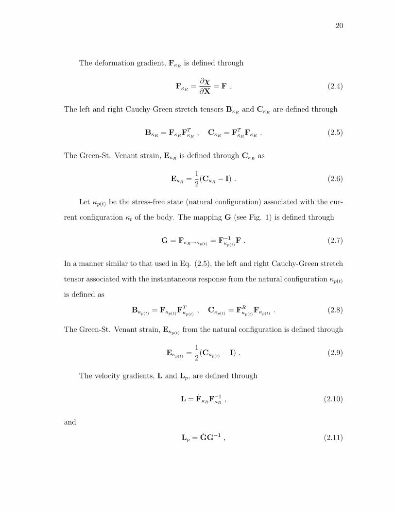
Let κR(B) and κt(B) denote (see Fig. 1) the reference and the current configura-
tion of the body B. Henceforth, for the sake of convenience, B in the notation κR(B),
19
c
b
a
F
G
( )p tκ
tκ
Rκ
( )p tκF
3e
2e
1e
′c ′b
′a
c
b
a
Fig. 1. Natural configurations associated with the body.
etc will be suppressed. The motion of a body can be defined as a one-to-one mapping
that assigns to each point X ∈ κR, a point x ∈ κt, for each t, i.e.
x = χκR(X, t) . (2.1)
The subscript κR is also dropped, for the sake of convenience. It is also assumed that
the motion is sufficiently smooth to render all the following operations meaningful.
The velocity of the particle is given by
v(X, t) =∂χ
∂t, (2.2)
while its acceleration is given by
a(X, t) =∂2χ
∂2t. (2.3)
20
The deformation gradient, FκRis defined through
FκR=
∂χ
∂X= F . (2.4)
The left and right Cauchy-Green stretch tensors BκRand CκR
are defined through
BκR= FκR
FTκR
, CκR= FT
κRFκR
. (2.5)
The Green-St. Venant strain, EκRis defined through CκR
as
EκR=
1
2(CκR
− I) . (2.6)
Let κp(t) be the stress-free state (natural configuration) associated with the cur-
rent configuration κt of the body. The mapping G (see Fig. 1) is defined through
G = FκR→κp(t)= F−1
κp(t)F . (2.7)
In a manner similar to that used in Eq. (2.5), the left and right Cauchy-Green stretch
tensor associated with the instantaneous response from the natural configuration κp(t)
is defined as
Bκp(t)= Fκp(t)
FTκp(t)
, Cκp(t)= FR
κp(t)Fκp(t)
. (2.8)
The Green-St. Venant strain, Eκp(t)from the natural configuration is defined through
Eκp(t)=
1
2(Cκp(t)
− I) . (2.9)
The velocity gradients, L and Lp, are defined through
L = FκRF−1
κR, (2.10)
and
Lp = GG−1 , (2.11)
21
where the dot signifies the usual material time derivative. The symmetric parts of L
and Lp are given, respectively, through:
D =1
2(L + LT ), Dp =
1
2(Lp + LT
p ) . (2.12)
The skew parts of L and Lp are given, respectively, through:
W =1
2(L− LT ), Wp =
1
2(Lp − LT
p ) . (2.13)
B. Kinetics
The purpose of kinetics is to link the motion and the deformation of a material body
to the outside influence which actually cause such a motion or deformation. The
concept of force is central to kinetics and it manifests either as a body force b or
surface tractions t. The body force b is due to the action of influences which are
not in direct contact with the body or a part of it which is being considered (the
most common example is the force due to gravity). The tractions t on the other
hand describe forces which act through the surface S that separates a body from its
outside environment.
The famous theorem due to Cauchy established the relation between the stress
tensor and the traction t on the surface S as
t(x, t,S) = TT (x, t)n , (2.14)
where n is the unit normal to S at the material point x, in the current configuration.
The second order tensor, T is known as the Cauchy stress tensor.

22
C. Balance laws
The manner in which a material body responds to the outside influence is governed
by certain balance laws of physics. These are balance of mass, balance of linear and
angular momentum and balance of energy1.
1. Balance of mass
The balance of mass states the physically observed phenomena that mass is temporally
constant for any given material body. The balance of mass states that
ρR = ρdet(F) , (2.15)
where ρR and ρ are the mass densities in the reference and current configuration,
respectively. Equation (2.15) is the Lagrangian form for the balance of mass. The
Eulerian statement in the local form for the balance of mass is given by
∂ρ
∂t+ div(ρv) = 0 . (2.16)
If the material is incompressible, the body can undergo only isochoric motions, which
implies that the density is a constant. Appealing to equation (2.16) immediately
leads to
div(v) = 0 , (2.17)
or equivalently
det(F) = 1 . (2.18)
1The balance of mass and energy do not necessarily hold individually (for exampleduring radioactive decay).
23
2. Balance of linear and angular momentum
The balance of linear momentum is basically Newton’s second law of motion written
for a continuum. The Eulerian statement for the balance of linear momentum in its
local form is
div(TT ) + ρb = ρv , (2.19)
where the dot signifies the usual material time derivative and b is the body force per
unit volume.
In the absence of body couples, the balance of angular momentum reduces to
T = TT , (2.20)
i.e. the Cauchy stress tensor is symmetric2.
3. Balance of energy
The notion of conservation of energy assumes a central role in physics. It stipulates
that the change in the energy of a system is equal to the transfer of the energy to the
system. The transfer of energy could occur in various forms such as heat transfer or
mechanical working. In describing the response of a body, one may need to specify a
constitutive equation for various modes of energy transfer such as mechanical, ther-
mal, chemical, electrical, etc. However, within the confines of a thermomechanical
process, only the mechanical and thermal modes come into picture. For a thermome-
chanical process, the balance of energy, in its local form takes the following form:
ρε + div(q) = T · L + ρr , (2.21)
2Cauchy stress tensor could be non symmetric in bodies such as micro-polar flu-ids. Also, in mixture theory [80], partial stresses of individual constituents is notsymmetric unless the angular momentum supply is zero.
24
where ε is the internal energy, q is the heat flux vector and r is the radiant heating.
D. Second law of thermodynamics
The second law of thermodynamics is commonly introduced in continuum mechanics
in the form of Clausius Duhem inequality (see Truesdell and Noll [97]). However,
in the current work, it will be introduced as an equality by introducing a balance
law for entropy. This approach follows from the work of Green and Naghdi [29] and
Rajagopal and Srinivasa [79]. The balance law for entropy takes the form
ρη + div(q
θ
)= ρ
r
θ+ ρξ , (2.22)
where η is the entropy, θ is the absolute temperature and ξ is the rate of entropy
production.
Combining the balance of energy, Eq. (2.21), and the balance of entropy, Eq.
(2.22) and eliminating the radiant heating term r, reduced energy-dissipation equation
is obtained:
T · L− ρε + ρθη − q · grad(θ)
θ= ρθξ := ζ ≥ 0 , (2.23)
where ζ is the rate of dissipation. The rate of entropy production ξ and the rate of
dissipation ζ is constrained to be non-negative for a physically acceptable process. In
any physical process, entropy production could take place due to a variety of reasons,
for e.g., due to mechanical working, heat conduction, phase change, chemical reactions
etc. For reversible processes, the rate of entropy production and hence the rate of
dissipation is identically zero. However, for irreversible processes, the rate of entropy
production is greater than zero.
The term −q·grad(θ)θ
in (2.23) is the rate of entropy production due to conduction.
It is a non-negative quantity, which is positive when temperature gradient exist in
25
the body and zero when there is no temperature gradient. It is usually assumed that
the rate of dissipation can be split into a part that is due to heat conduction (ζc) and
another part due to mechanical working (ζm). Such a split leads us to
T · L− ρψ − ρηθ = ζm ≥ 0 , (2.24)
−q · grad(θ)
θ= ζc ≥ 0 . (2.25)
Assuming the heat flux vector to be of the form
q = −Λ grad(θ) , (2.26)
where Λ is the thermal conductivity and is required to be non-negative, ensures that
condition (2.25) is met.
E. Material frame indifference
The notion of material frame indifference requires that the physical quantities such
as scalars, vectors and tensors that are used in a constitutive theory should remain
invariant to superposed rigid body motion (Truesdell and Noll [97]).
Let us consider a material point X which is occupying some position in the cur-
rent configuration. The location of the material point X in the current configuration
is seen as (x, t) and (x∗, t∗) in two frames which are related to each other through
rigid body motion of the form
x∗ = c(t) + Q(t)(x− xo), t∗ = t− to , (2.27)
where c(t) is an arbitrary vector function of time, Q(t) is an arbitrary orthogonal
tensor and to is a constant.
A scalar, vector or a tensor is said to be frame-indifferent if under a change of
26
frame they are related through:
φ∗ = φ , v∗ = Qv , T∗ = QTQT . (2.28)
It follows from Eq. (2.28) and the definition of deformation gradient that
F∗κR= QFκR
. (2.29)
As the underlying natural configuration associated with the body is continuously
evolving and the Cauchy stress is represented with respect to the stress free configu-
ration or the natural configuration, it is also required that the invariance requirement
on F and Fκp(t)are the same, i.e.,
F∗κp(t)= QFκp(t)
. (2.30)
It follows from Eqs. (2.7), (2.29) and (2.30) that
G∗ = G . (2.31)
The various quantities such as specific Helmholtz potential and rate of dissipation
function that will be used in our constitutive theory will be required to satisfy the
constraint due to material frame indifference:
ψ(F∗κp(t),G∗, θ∗) = ψ(QFκp(t)
,G, θ) ,
ξ(F∗κp(t),G∗,L∗p, θ
∗) = ξ(QFκp(t),G,Lp, θ) .
(2.32)
F. Theory of simple materials and single crystals
A material is said to be a simple material (see Noll [60]) if the stress T can be deter-
mined purely by the history of the deformation gradient and within a thermodynamic
27
context, the history of the temperature, i.e.,
T = F∞τ=0[F(t− τ), θ(t− τ)] . (2.33)
Classical models for elastic solids take the form
T = f(F, θ) , (2.34)
and it belongs to the class of models given by (2.33). The classical viscous fluid model
T = f(ρ,D) , (2.35)
also belong to the same class. Moreover most of the models developed to describe
viscoelastic materials such as fluids of grade n also belong to the class of simple
fluids. The models given by (2.33) are inadequate to describe the inelastic response
of materials. Traditional models for polycrystalline plasticity do not fall into the class
(2.33) (see Rajagopal and Srinivasa [72]).
We shall now discuss an important property of single crystals that implies that
the model cannot belong to the class defined by (2.33), and this concerns with the
inability of such models to depict the evolution of the anisotropy of the single crystal
as it undergoes inelastic deformation. Let us now begin by defining the notion of
symmetry group at a material point.
The symmetry group associated with a material point belonging to the material,
which reflects the physical symmetry of the material, is defined through
Gκ = H ⊂ U | fκ(FκH) = fκ(Fκ) , (2.36)
where U is the unimodular group and the dependence on temperature is suppressed.
If κ1 and κ2 are two configurations of the body (see Fig. 2), then it follows that Gκ1

28
Fig. 2. Noll’s rule for simple materials.
and Gκ2 are related through the gradient of the mapping λ from κ1 to κ2 (Noll’s rule):
Gκ2 = PGκ1P−1 , (2.37)
where
P := ∇λ . (2.38)
If a single crystal were to be a simple material, and if κ1 and κ2 represent two
configurations of the single crystal, then Gκ1 and Gκ2 should be related by Noll’s rule.
Now, if a single crystal is sheared and the corresponding mapping P determined, then
we can ask if Gκ1 and Gκ2 are related by Noll’s rule. If shear along a slip plane of the
crystal leaves the material symmetry unchanged, it immediately follows that (2.37)
is not met.
Experiments have clearly shown that the lattice structure and hence the material
symmetry remains the same when a single crystal is sheared sufficiently so that “slip”
takes place (see Fig. 3). In their seminal paper on single crystals, Taylor and Elam
[92] made the following observations:
“moreover, measurements of the inclination of two different crystal
planes during the present experiments showed that the angle between
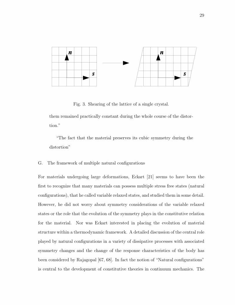
29
Fig. 3. Shearing of the lattice of a single crystal.
them remained practically constant during the whole course of the distor-
tion.”
“The fact that the material preserves its cubic symmetry during the
distortion”
G. The framework of multiple natural configurations
For materials undergoing large deformations, Eckart [21] seems to have been the
first to recognize that many materials can possess multiple stress free states (natural
configurations), that he called variable relaxed states, and studied them in some detail.
However, he did not worry about symmetry considerations of the variable relaxed
states or the role that the evolution of the symmetry plays in the constitutive relation
for the material. Nor was Eckart interested in placing the evolution of material
structure within a thermodynamic framework. A detailed discussion of the central role
played by natural configurations in a variety of dissipative processes with associated
symmetry changes and the change of the response characteristics of the body has
been considered by Rajagopal [67, 68]. In fact the notion of “Natural configurations”
is central to the development of constitutive theories in continuum mechanics. The

30
crucial role it plays in describing the response of a broad range of material behaviors
has not been recognized and delineated in detail until the recent work of Rajagopal
[67, 68]. Invoking the notion of “natural configurations” has led to the development
of constitutive theories which has filled the lacunae that existed in incorporating the
microstructural details from a continuum perspective. It has led to development of
constitutive theories with rigorous thermodynamic underpinnings without resorting
to any ad hoc means such as invoking “internal variables” into the theory. The
phenomenal success of such a framework in describing the response of a disparate class
of materials can be seen in a series of papers by Rajagopal and coworkers: the response
of multi-network polymers [102, 81], twinning [70, 71], traditional plastic response
[72, 73], solid to solid phase transitions [70, 71], shape memory alloys [74], viscoelastic
response [75], anisotropic response of liquids [76], crystallization of polymers [83],
superplastic response [69], response of asphalt mixtures [51], growth and adaptation
of biological materials [82] and response of superalloys [65]. The classical theories of
elasticity and linearly viscous fluid arise naturally as sub-cases.
The framework of multiple natural configurations exploits the fact that the con-
figuration that the body would attain on the removal of external stimuli, referred to as
“natural configuration”, evolves, with the response of the body being non-dissipative
(in more general situations non entropy producing) from these evolving natural config-
urations. The evolution of these natural configurations is determined by the tendency
of the body to undergo a process that maximizes the rate of dissipation. Different
natural configurations are accessed during different processes. It is suffice to say that
the notion of natural configuration is a primitive in our framework and it can be
thought of as one of the state variables in the constitutive theory.

31
CHAPTER III
A CONTINUUM MODEL FOR CREEP OF SUPERALLOYS
A. Development of constitutive model
Let us now start with the reduced energy dissipation equation (see Green and Naghdi
[29]):
T · L− ρψ − ρηθ − q · grad(θ)
θ= ρθξ := ζ ≥ 0 , (3.1)
which is a different version of Eq. (2.23) obtained by substituting ψ = ε− θη, where
ψ is the Helmholtz potential.
In what follows, the effect of temperature is ignored and an isothermal model is
developed. The motivation to develop an isothermal model stems from the fact that all
the creep experiments are done at a constant temperature. The material parameters
that will appear in the constitutive model will be different for different temperatures.
In chapter VI, a framework for a non-isothermal model has been developed.
Splitting the entropy production part as that due to thermal effects and a part
due to mechanical dissipation lead us to,
T · L− ρψ = ζmech ≥ 0 . (3.2)
Equation (3.2) is the starting point for the development of a isothermal constitutive
model.
The form for the stored energy of the crystalline materials is assumed to be
ψ = ψ(Fκp(t),G) . (3.3)
It is assumed that the Helmholtz potential can be decomposed in the following way:
ψ = ψ + ψ , (3.4)
32
where
ψ = ψκp(t)(Fκp(t)
) , (3.5)
is related to the elastic stored energy, and
ψ = F∞τ=0[G(t− τ)] , (3.6)
is related to the inelastic stored energy. A standard rearrangement will yield
[T− ρ
∂ψ
∂Fκp(t)
FTκp(t)
]· L + ρFT
κp(t)
∂ψ
∂Fκp(t)
· Lp − ρdψ
dt= ζmech ≥ 0 . (3.7)
It is now assumed that the Cauchy stress is of the form
T = ρ∂ψ
∂Fκp(t)
FTκp(t)
= ρFκp(t)
∂ψ
∂Eκp(t)
FTκp(t)
. (3.8)
On using equation (3.8), equation (3.7) can be reduced to
(FTκp(t)
TF−Tκp(t)
) · Lp − ρdψ
dt= ζmech . (3.9)
Decomposing (FTκp(t)
TF−Tκp(t)
) into symmetric and skew parts and using the polar de-
composition (Fκp(t)= Vκp(t)
Rκp(t)) leads to
A ·Dp + τ ·Wp − ρdψ
dt= ζmech , (3.10)
where
A = (FTκp(t)
TF−Tκp(t)
)sym =1
2RT
κp(t)(Vκp(t)
TV−1κp(t)
+ V−1κp(t)
TVκp(t))Rκp(t)
, (3.11a)
τ = (FTκp(t)
TF−Tκp(t)
)skew =1
2RT
κp(t)(Vκp(t)
TV−1κp(t)
−V−1κp(t)
TVκp(t))Rκp(t)
. (3.11b)
For a material that is elastically isotropic, T will be an isotropic function of Vκp(t)so
that τ = 0.

33
The rate of dissipation due to creep is assumed to be of the form
ζmech = ζ1(θ,Dp) + ζ2(θ,Wp) , (3.12)
i.e., the rate of dissipation depends both upon the rate at which the material stretches
as well as the rate at which the orientation changes. For a specimen loaded in any
arbitrary orientation, the crystal lattice rotates. However, for uniaxial creep loading
along orientations <001>, <111> and <011>, there is no associated rotation of the
crystal lattice.
Equation (3.12) with equation (3.10) yields
A ·Dp − ρdψ
dt= ζ1(θ,Dp) , τ ·Wp = ζ2(θ,Wp) . (3.13)
B. Specific constitutive relations
1. The Helmholtz potential ψ
The specific form for the elastic stored energy consistent with a crystal having cubic
symmetry is
ψ =1
2ρ
[c12(tr Eκp(t)
)2 + 2c44(tr E2κp(t)
) + (c11 − c12 − 2c44)((a · Eκp(t)
a)2+
(b · Eκp(t)b)2 + (c · Eκp(t)
c)2)]
,
(3.14)
where a, b and c are orthogonal unit vectors along the principal cubic axes and c11,
c12 and c44 are three independent parameters characterizing the elastic response.
2. Inelastic part of the stored energy ψ
The form for the inelastic stored energy captures the part of mechanical work that
is trapped in the dislocation networks. Models due to Lee [40], Brown et al. [5] and
Mason et al. [46] account for this kind of energy storage mechanism in the body by

34
multiplying the “plastic work” by an ad hoc factor whose value is approximately
0.8. The current work utilizes a rigorous form for such an energy storage mechanism
without resorting to any ad hoc means. The energy that is stored in dislocation net-
works is of tremendous importance during the inelastic deformation of single crystal
superalloys as such superalloys are multi phase materials with their microstructure
engineered in such a way to ensure solid solution hardening and precipitation hard-
ening.
We will assume the following form for the inelastic part of the free energy ψ
developed by Mollica et al., [50] and subsequently used by Prasad et al., [65]:
ψ = ψ1a(s) + ψ2
∫ s
0
eη(x−s)(Ep(s)− Ep(x)) ·N(x)dx , (3.15)
where the scalar variable s = s(t) is referred to as “inelastic strain pathlength” and
is defined as
s = (Dp ·Dp)12 , (3.16)
ψ1, ψ2 and η are material constants and
Ep =
∫ t
0
Dp(τ)dτ , (3.17)
N =Dp
(Dp ·Dp)12
. (3.18)
Ep is a measure of accumulated inelastic strain with reference to reference configura-
tion and it can be described as a measure of the total amount of slip that has taken
place on slip systems which are active [59].
Also, a(s) is the density of the dislocation network (defined as the total length
of dislocation lines per unit volume [85]) and assumes the following form:
a(s) = ao(1 + β2(1− e−α1s)) . (3.19)

35
The motivation to choose such a form stems from the experimental observation that
the dislocation density increases with monotonic inelastic deformation and reaches a
saturation value after a while.
The time rate of change of ψ (3.15) is given by
ρdψ
dt= ρ
[ψ1
(a′ + ηa
)− ηψ
](Dp ·Dp)
12 +
(ρψ2
∫ s
0
eη(x−s)N(x)dx
)·Dp ,
:= h(s)(Dp ·Dp)12 + α ·Dp ,
(3.20)
where (·)′ denotes the total derivative with respect to s.
The tensor
α = ρψ2
∫ s
0
eη(x−s)N(x)dx , (3.21)
is the backstress tensor. On taking the time derivative of (3.21), it can be seen that
the backstress, α would satisfy the following evolution equation:
α = ρψ2Dp − η(Dp ·Dp)12 α , (3.22)
which is a generalized version of the non-linear kinematic hardening rule [12]. Al-
though no experimental data concerning the inelastic stored energy is available, to
our knowledge, for single crystal superalloys, there are experimental data for polycrys-
talline metals [3, 101]. Apart from the experiments, several attempts have been made
to model the inelastic stored energy (see for example, papers by Chaboche [13, 14]
and Kamlah and Haupt [36]). The inelastic stored energy might not be significant at
high temperatures at which creep occurs as only a small fraction of energy is stored
(dissipation mechanisms being dominant).
36
3. Rate of dissipation
Following form for the rate of dissipation is assumed:
ζ1 = Dp ·KDp , ζ2 = η2Wp ·Wp , (3.23)
where K is a fourth order tensor reflecting cubic symmetry that is a function of the
temperature, the inelastic history of the material and the driving force:
K = k12I⊗ I + 2k44I4 + (k11 − k12 − 2k44)N , (3.24)
where I4 is the fourth order identity tensor, and the fourth order tensor N has the
form
Nijkl = aiajakal + bibjbkbl + cicjckcl . (3.25)
ai, bi and ci are the components of the orthogonal unit vectors a, b and c.
The evolution equation for the natural configuration is determined by the ten-
dency of the body to undergo a process that maximizes the rate of dissipation. The
idea of maximization of rate of dissipation is not a fundamental principle of thermo-
dynamics. However it is also not ad hoc either. It is a generalization of a notion
due to Gibbs that an isolated system tends to a state of maximal entropy. A further
assumption is made that the way, the body gets to the state of maximal entropy
is by producing entropy at the maximal possible rate (see Rajagopal and Srinivasa
[77, 78]).
Maximizing the rate of dissipation subject to the constraint tr(Dp) = 0 (inelastic
deformation being isochoric) gives the following equations for Dp and Wp:
A = pI + A∗ , (3.26a)
A∗ = α + KDp + h(s)Dp
(Dp ·Dp)12
, (3.26b)

37
p =1
3tr(A−A∗) , (3.26c)
and
Wp =1
η2
τ . (3.27)
The rate of dissipation functions ζ1 and ζ2 defined through (3.23) are required to
be non-negative. Our constitutive assumption for the rate of dissipation ensures that
it is non-negative. It can be seen from equation (3.23) that the rate of dissipation is
dependent on the fourth order tensor K which is anisotropic. It is assumed that two
mechanisms contribute to the rate of dissipation in the following way:
The first mechanism is related to the dissipation caused by mobile dislocations.
There is a rapid multiplication of dislocations in the γ matrix at the beginning of
creep. It is observed that the γ′ phase is “hard” for significant amount of creep strains
and hence no dislocation activity is associated with it. As the deformation increases,
these dislocations start moving in the γ matrix. Further deformation results in these
dislocations being stuck and bowed. This causes “hardening” of the material. In order
to describe the loss of mobility of the dislocations with accumulating “creep strain”,
it is assumed that the mean velocity of the dislocations remains constant at constant
stress while the density of dislocations, which are mobile decay exponentially. That
is, only a fraction of the total remains mobile. Let f be this fraction. In accordance
with the work of Gilman [28], following form for the mobile fraction is assumed:
f = eα2s, (3.28)
where α2 is the attrition coefficient.
The density of mobile dislocations, am(s) is then given by
am(s) = a(s)f = ao(1 + β2(1− e−α1s))e−α2s. (3.29)

38
The first mechanism of dissipation is assumed to be proportional to the inelastic
strain pathlength, s(t) in the following way:
ζ1 ∝ am(s). (3.30)
Apart from this, the dissipation mechanism, in general, also depends upon the driving
force, as most dislocation interactions become less inhibitory with increasing driving
force.
The second mechanism associated with dissipation is related to the damage ac-
cumulation by creep cavitation. With the creep strain accumulating, the material
starts getting “damaged” by means of highly localized deformation in the vicinity of
crack surfaces. As reported in numerous experiments, this creep elongation at the
later stage of deformation is associated with creep cavitation occurring at, or in the
vicinity of casting porosity and topologically closed-packed phases. Hence this stage is
marked by a rapid increase in the strain (“softening”). Moreover, experiments clearly
indicate that the effect of highly localized damage due to creep cavitation becomes
dominant only after a certain critical strain is reached. The second mechanism of
dissipation is assumed to be proportional to the inelastic strain pathlength, s(t) in
the following way:
ζ1 ∝ eα3s. (3.31)
Moreover, it is also assumed that this second mechanism of dissipation remains active
throughout the creep process but becomes dominant only in the later stages of creep.
This second mechanism, in general, is also dependent on the driving force.
39
The coefficients associated with the tensor K have the following form:
k11 − k12 =1
β1eκ1tr(A)a(s)e−α2s + β3eκ2tr(A)eα3s,
k44 =0.5
Λ1eΓ1tr(A)a(s)e−Ω2s + Λ3eΓ2tr(A)eΩ3s.
(3.32)
It should be noted that k11−k12 and k44 have the same form. The material parameters
ψ1, ψ2, η, β2 and α1 which are associated with the inelastic stored energy do not change
with the orientation of the crystal. The form for the rate of dissipation function is
motivated based on creep deformation when the specimen is loaded along the <001>
and the <111> directions. The coefficients k11 − k12 and k44 reflect the dissipation
which takes place when the specimen is loaded in the <111> and the <001> direction,
respectively. Such a description is a simplistic one and we will see that it captures
the creep deformation of single crystal superalloys reasonably well. The dependence
of rate of dissipation on dislocation motion is much more intricate when the specimen
is loaded along arbitrary directions.
4. Instantaneous rate of energy storage, R
One of the important quantities in any inelastic process is the ratio of rate of energy
stored to the rate of work done by the externally applied tractions. The rate at which
work is done during the inelastic process by the applied tractions per unit mass is
given by
wi(t) =T · L
ρ. (3.33)
The rate of dissipation per unit mass is given by
wd(t) =ζmech
ρ=
1
ρ(Dp ·KDp + η2Wp ·Wp). (3.34)
40
The rate of energy stored per unit mass is given by ψ. The instantaneous rate of
energy storage, R is then given by
R =ws(t)
wi(t)= 1− wd(t)
wi(t), (3.35)
where the equation of balance of energy is utilized in the form of reduced energy
dissipation equation (equation (3.2)). Although no experiments have been conducted,
to our knowledge, on single crystal superalloys to measure such a quantity, there are
some experimental results for polycrystalline metals (see Williams [101]) which can
provide some guidance in our choice for the same for single crystal superalloys.
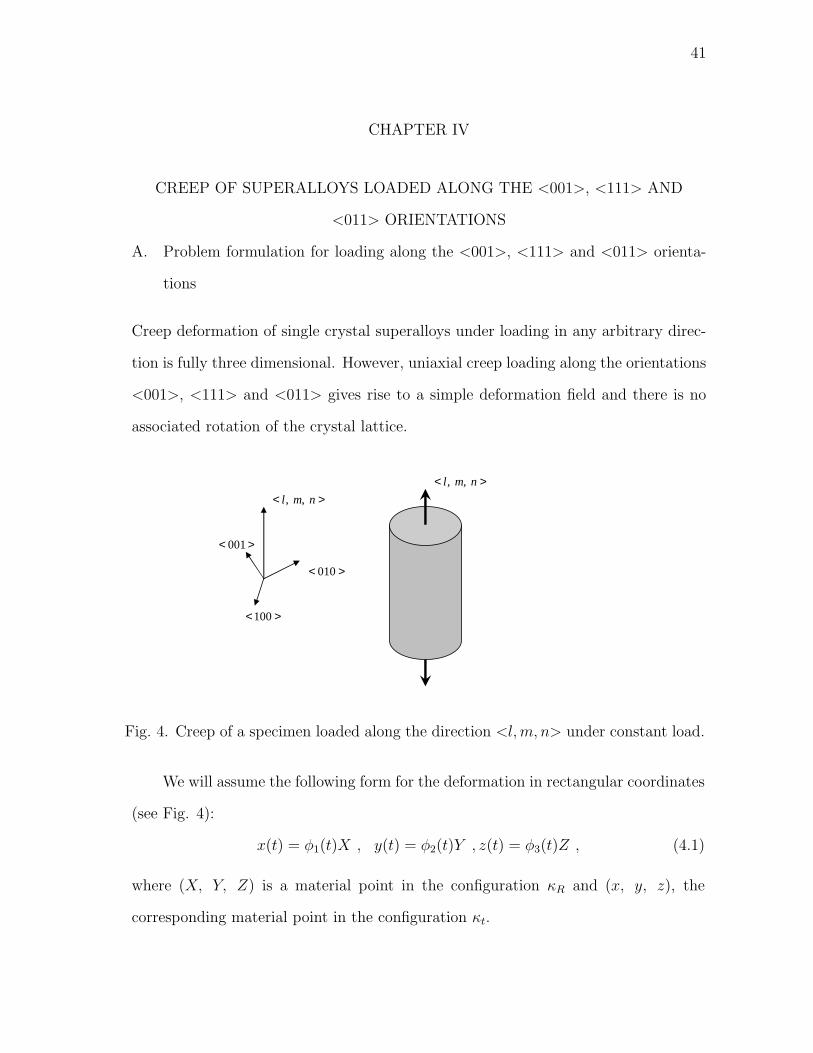
41
CHAPTER IV
CREEP OF SUPERALLOYS LOADED ALONG THE <001>, <111> AND
<011> ORIENTATIONS
A. Problem formulation for loading along the <001>, <111> and <011> orienta-
tions
Creep deformation of single crystal superalloys under loading in any arbitrary direc-
tion is fully three dimensional. However, uniaxial creep loading along the orientations
<001>, <111> and <011> gives rise to a simple deformation field and there is no
associated rotation of the crystal lattice.
100< >
010< >
001< >
, , l m n< >
, , l m n< >
Fig. 4. Creep of a specimen loaded along the direction <l, m, n> under constant load.
We will assume the following form for the deformation in rectangular coordinates
(see Fig. 4):
x(t) = φ1(t)X , y(t) = φ2(t)Y , z(t) = φ3(t)Z , (4.1)
where (X, Y, Z) is a material point in the configuration κR and (x, y, z), the
corresponding material point in the configuration κt.

42
The deformation gradient associated with the above motion is given by
F = diag( φ1(t), φ2(t), φ3(t)) . (4.2)
The elastic response consistent with the above deformation is given by
x(t) = λ1X∗(t) , y(t) = λ2Y
∗(t) , z(t) = λ3Z∗(t) , (4.3)
where (X∗, Y ∗, Z∗) ∈ κp(t). The deformation gradient and the corresponding Green-
St. Venant strain tensor associated with the elastic response from the natural config-
uration is given by
Fκp(t)= diag( λ1, λ2, λ3) , Eκp(t)
=1
2diag( λ2
1 − 1, λ22 − 1, λ2
3 − 1) . (4.4)
Specimens with orientation along <001> and <111> exhibit no shear strains and the
transverse strains are equal (i.e., φ1 = φ2 and λ1 = λ2). For specimens loaded along
<011>, there is no associated shear strains but the two transverse strains are not
equal.
We will assume that the creep deformation takes place at constant stress, that
is,
T = diag( 0, 0, Tzz) , (4.5)
which leads to
A = diag( 0, 0, Tzz) , τ = 0 , p =1
3Tzz . (4.6)
Substituting the form for the elastic stored energy (Eq. (3.14)) into the constitutive
equation for the elastic response (Eq. (3.8)), we obtain the governing equations for
the elastic response from the natural configuration:
c12(tr Eκp(t))Fκp(t)
FTκp(t)
+ 2c44Fκp(t)Eκp(t)
FTκp(t)
+(c11 − c12 − 2c44)Fκp(t)(NEκp(t)
)FTκp(t)
= T .
(4.7)
43
The unit vectors along the principal cubic axes, which constitutes the fourth order
tensor N are given by
a =
(Λ2
Λ1
, 0,l
Λ1
), b =
(− ml
Λ1Λ2
,n
Λ2
,m
Λ1
), c =
(− nl
Λ1Λ2
, − m
Λ2
,n
Λ1
), (4.8)
where
Λ1 =√
l2 + m2 + n2 , Λ2 =√
m2 + n2 , (4.9)
with the loading axis along la + mb + nc.
The tensor G, for the assumed deformation is given by
G = diag
(φ1(t)
λ1
,φ2(t)
λ2
,φ3(t)
λ3
). (4.10)
The symmetric and skew part of Lp are given by
Dp = diag
(φ1(t)
φ1(t),
φ2(t)
φ2(t),
φ3(t)
φ3(t)
), Wp = 0 , (4.11)
and the time derivative of inelastic strain pathlength s is given by
s =
√√√√(
φ1(t)
φ1(t)
)2
+
(φ2(t)
φ2(t)
)2
+
(φ3(t)
φ3(t)
)2
. (4.12)
A straightforward application of constitutive relations (3.26a)-(3.26c) will lead
us to (h
s+ 2k44
)φi(t)
φi(t)+ (NDp)i = (A)i − p− (α)i , (4.13a)
(α)i = ρψ2φi(t)
φi(t)− ηs(α)i , i = 1− 3 (no sum on i) , (4.13b)
˙ψ =1
ρ
(hs + (α)1
φ1(t)
φ1(t)+ (α)2
φ2(t)
φ2(t)+ (α)3
φ3(t)
φ3(t)
), (4.13c)
where ()i denotes the i-th diagonal element of the respective second order tensors.
Equations (4.12) and (4.13a)-(4.13c) form the set of governing non-linear ordinary

44
differential equations.
The instantaneous rate of energy storage, R which is the ratio of rate of energy
stored to the rate of work done by applied tractions is given by
R = 1− wd(t)
wi(t)= 1− ζmech
T · L , (4.14)
where wd(t) is the rate of dissipation per unit mass and wi(t) is the specific stress
power.
B. Results for loading along the <001> orientation
The creep strain was obtained by integrating equations (4.12)-(4.13c) over time.
Equations (4.12)-(4.13c) are solved using a solver (ODE15S) for initial value problems
in MATLAB.
The results were obtained for a range of temperatures, which are pertinent to
the problem under consideration. The material parameters, in general, are functions
of temperature. Simulation was carried out at three different temperatures at various
stress values and the results are compared with the experimental results for CMSX-
4 ([90] and [32]). The values of parameters characterizing the elastic response at
different temperatures are listed in Table V and the values of material parameters for
different temperatures are listed in Table VI.
Table V. Parameters characterizing the elastic response of CMSX-4 at various tem-
peratures [88].
θ 750oC 800oC 950oC 982oC 1000oC
c11 (GPa) 229.7 223 214.8 213.2 208.4
c12 (GPa) 149.3 145.6 141.4 140.9 138.4
c44 (GPa) 115 112 107 106 104

45
Table VI. Material parameters for CMSX-4 at various temperatures for loading along
the <001> orientation.
θ 750oC 982oC 1000oC
δ1 1.8 1.07 3
δ2 1.5× 10⁵ 1.02× 10⁴ 5× 10⁴
η 40 39.21 50
κ1 1.7× 10⁻⁸ 1.42× 10⁻⁸ 1.2× 10⁻⁷
κ2 2.77× 10⁻⁸ 2.87× 10⁻⁸ 1.7× 10⁻⁸
β1 1× 10⁻²³ 8.27× 10⁻¹⁹ 8.77× 10⁻²⁶
β2 1800 478 272
α1 3 2.95 1.1
α2 66 0 1817
β3 1× 10⁻²⁹ 7.9× 10⁻²¹ 3.53× 10⁻¹⁸
α3 25.2 27.61 39.1
The variation of creep strain, instantaneous rate of energy storage and inelastic
stored energy with time are presented for different temperatures at various stresses.
The variation of creep strain with time for θ = 750, 982 and 1000 oC are shown in
Figs. 5, 6 and 7. It can be seen that the predictions of the model agree well with the
experimental data for the different temperatures considered here. Figs. 8, 9 and 10
46
depict the variation of the inelastic stored energy with respect to the inelastic strain
pathlength. Also, Figs. 11, 12 and 13 represent the variation of third component
of backstress tensor with inelastic strain pathlength. Variation of the instantaneous
rate of energy storage with inelastic strain pathlength is also studied. It can be
seen from Figs. 14, 15 and 16 that the material stores energy in the initial stages
of deformation but as the deformation proceeds most of the energy is dissipated.
Moreover, it can be observed that the fraction of energy stored decreases at higher
temperatures. That is, at higher temperatures most of the work done by the applied
tractions is dissipated. This is to be expected as the dislocation motion which is
primarily the source of dissipation becomes less and less inhibitory as the temperature
increases. The inelastic stored energy increases with inelastic deformation but its
value seems to be attaining a saturation value. The driving force doesn’t seem to
have significant effect on the variation of inelastic stored energy as the curves for
the different stresses lie almost on top of each other. The driving force however, has
significant effect on the rate of dissipation as dissipation mechanisms themselves are
strongly dependent on the driving force.
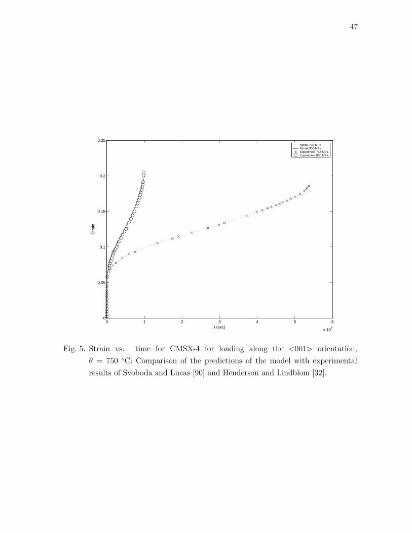
47
0 1 2 3 4 5 6
x 106
0
0.05
0.1
0.15
0.2
0.25
t (sec)
Str
ain
Model 735 MPaModel 800 MPaExperiment 735 MPaExperiment 800 MPa
Fig. 5. Strain vs. time for CMSX-4 for loading along the <001> orientation,
θ = 750 oC: Comparison of the predictions of the model with experimental
results of Svoboda and Lucas [90] and Henderson and Lindblom [32].

48
0 1 2 3 4 5 6
x 106
0
0.05
0.1
0.15
0.2
0.25
0.3
0.35
t (sec)
Str
ain
Model 167.5 MPaModel 206.9 MPaModel 248.2 MPaExperiment 167.5 MPaExperiment 206.9 MPaExperiment 248.2 MPa
Fig. 6. Strain vs. time for CMSX-4 for loading along the <001> orientation,
θ = 982 oC: Comparison of the predictions of the model with experimental
results of Svoboda and Lucas [90] and Henderson and Lindblom [32].
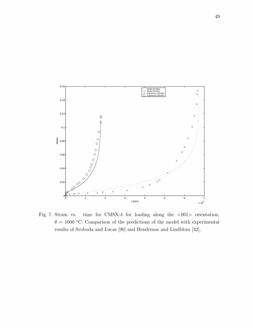
49
0 1 2 3 4 5 6 7
x 106
0
0.02
0.04
0.06
0.08
0.1
0.12
0.14
0.16
t (sec)
Str
ain
Model 150 MPaModel 200 MPaExperiment 150 MPaExperiment 200 MPa
Fig. 7. Strain vs. time for CMSX-4 for loading along the <001> orientation,
θ = 1000 oC: Comparison of the predictions of the model with experimental
results of Svoboda and Lucas [90] and Henderson and Lindblom [32].

50
0 0.05 0.1 0.15 0.2 0.250
200
400
600
800
1000
1200
1400
1600
1800
s
ψp
Model 735 MPaModel 800 MPa
Fig. 8. Inelastic stored energy vs. inelastic strain pathlength for CMSX-4 for loading
along the <001> orientation, θ = 750 oC: Predictions of the model.

51
0 0.05 0.1 0.15 0.2 0.25 0.3 0.350
50
100
150
200
250
300
350
s
ψp
Model 167.5 MPaModel 206.9 MPaModel 248.2 MPa
Fig. 9. Inelastic stored energy vs. inelastic strain pathlength for CMSX-4 for loading
along the <001> orientation, θ = 982 oC: Predictions of the model.
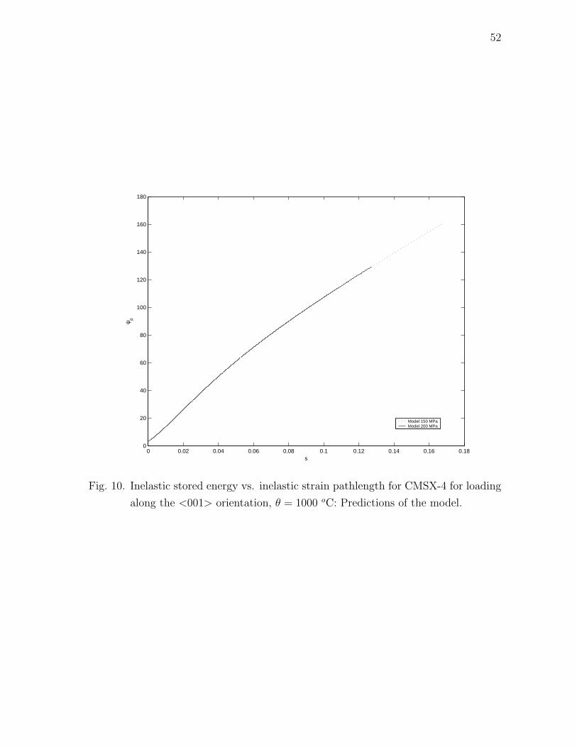
52
0 0.02 0.04 0.06 0.08 0.1 0.12 0.14 0.16 0.180
20
40
60
80
100
120
140
160
180
s
ψp
Model 150 MPaModel 200 MPa
Fig. 10. Inelastic stored energy vs. inelastic strain pathlength for CMSX-4 for loading
along the <001> orientation, θ = 1000 oC: Predictions of the model.

53
0 1 2 3 4 5 6
x 106
0
0.5
1
1.5
2
2.5
3x 10
7
s
α 33
Model 735 MPaModel 800 MPa
Fig. 11. Third component of backstress vs. inelastic strain pathlength for CMSX-4 for
loading along the <001> orientation, θ = 750 oC: Predictions of the model.

54
0 0.05 0.1 0.15 0.2 0.250
0.2
0.4
0.6
0.8
1
1.2
1.4
1.6
1.8
2x 10
6
s
α 33
Model 167.5 MPaModel 206.9 MPaModel 248.2 MPa
Fig. 12. Third component of backstress vs. inelastic strain pathlength for CMSX-4 for
loading along the <001> orientation, θ = 982 oC: Predictions of the model.
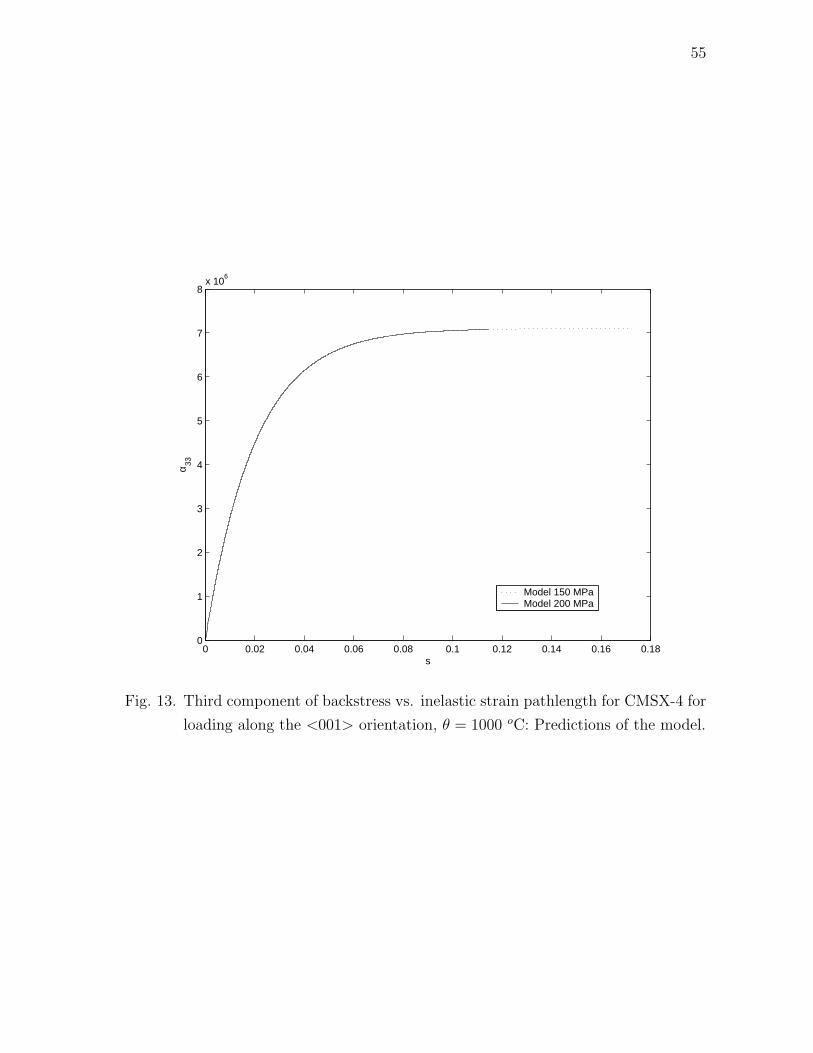
55
0 0.02 0.04 0.06 0.08 0.1 0.12 0.14 0.16 0.180
1
2
3
4
5
6
7
8x 10
6
s
α 33
Model 150 MPaModel 200 MPa
Fig. 13. Third component of backstress vs. inelastic strain pathlength for CMSX-4 for
loading along the <001> orientation, θ = 1000 oC: Predictions of the model.
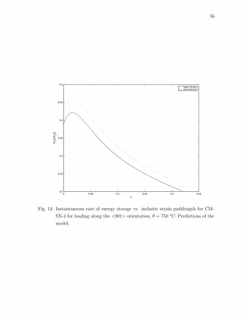
56
0 0.05 0.1 0.15 0.2 0.250.2
0.25
0.3
0.35
0.4
0.45
0.5
s
Ws(t
)/W
p(t)
Model 735 MPaModel 800 MPa
Fig. 14. Instantaneous rate of energy storage vs. inelastic strain pathlength for CM-
SX-4 for loading along the <001> orientation, θ = 750 oC: Predictions of the
model.

57
0 0.05 0.1 0.15 0.2 0.25 0.3 0.350.05
0.1
0.15
0.2
0.25
0.3
s
Ws(t
)/W
p(t)
Model 167.5 MPaModel 206.9 MPaModel 248.2 MPa
Fig. 15. Instantaneous rate of energy storage vs. inelastic strain pathlength for CM-
SX-4 for loading along the <001> orientation, θ = 982 oC: Predictions of the
model.

58
0 0.02 0.04 0.06 0.08 0.1 0.12 0.14 0.16 0.180.12
0.14
0.16
0.18
0.2
0.22
0.24
0.26
0.28
0.3
s
Ws(t
)/W
p(t)
Model 150 MPaModel 200 MPa
Fig. 16. Instantaneous rate of energy storage vs. inelastic strain pathlength for CM-
SX-4 for loading along the <001> orientation, θ = 1000 oC: Predictions of
the model.
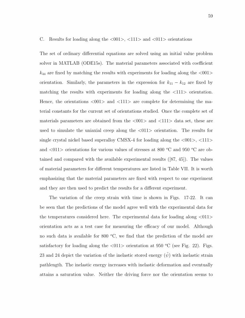
59
C. Results for loading along the <001>, <111> and <011> orientations
The set of ordinary differential equations are solved using an initial value problem
solver in MATLAB (ODE15s). The material parameters associated with coefficient
k44 are fixed by matching the results with experiments for loading along the <001>
orientation. Similarly, the parameters in the expression for k11 − k12 are fixed by
matching the results with experiments for loading along the <111> orientation.
Hence, the orientations <001> and <111> are complete for determining the ma-
terial constants for the current set of orientations studied. Once the complete set of
materials parameters are obtained from the <001> and <111> data set, these are
used to simulate the uniaxial creep along the <011> orientation. The results for
single crystal nickel based superalloy CMSX-4 for loading along the <001>, <111>
and <011> orientations for various values of stresses at 800 oC and 950 oC are ob-
tained and compared with the available experimental results ([87, 45]). The values
of material parameters for different temperatures are listed in Table VII. It is worth
emphasizing that the material parameters are fixed with respect to one experiment
and they are then used to predict the results for a different experiment.
The variation of the creep strain with time is shown in Figs. 17-22. It can
be seen that the predictions of the model agree well with the experimental data for
the temperatures considered here. The experimental data for loading along <011>
orientation acts as a test case for measuring the efficacy of our model. Although
no such data is available for 800 oC, we find that the prediction of the model are
satisfactory for loading along the <011> orientation at 950 oC (see Fig. 22). Figs.
23 and 24 depict the variation of the inelastic stored energy (ψ) with inelastic strain
pathlength. The inelastic energy increases with inelastic deformation and eventually
attains a saturation value. Neither the driving force nor the orientation seems to
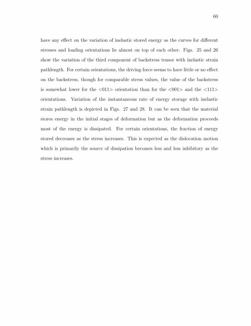
60
have any effect on the variation of inelastic stored energy as the curves for different
stresses and loading orientations lie almost on top of each other. Figs. 25 and 26
show the variation of the third component of backstress tensor with inelastic strain
pathlength. For certain orientations, the driving force seems to have little or no effect
on the backstress, though for comparable stress values, the value of the backstress
is somewhat lower for the <011> orientation than for the <001> and the <111>
orientations. Variation of the instantaneous rate of energy storage with inelastic
strain pathlength is depicted in Figs. 27 and 28. It can be seen that the material
stores energy in the initial stages of deformation but as the deformation proceeds
most of the energy is dissipated. For certain orientations, the fraction of energy
stored decreases as the stress increases. This is expected as the dislocation motion
which is primarily the source of dissipation becomes less and less inhibitory as the
stress increases.

61
Table VII. Material parameters for CMSX-4 at various temperatures.
Parameter / θ 800 oC 950 oC
ψ1 1.5 3
ψ2 1.5 x 10⁵ 5 x 10⁴
η 40 40
α1 3 2
β2 100 245
β1 4.47 x 10⁻²⁵ 6.5 x 10⁻¹⁹
κ1 1.1 x 10⁻⁷ 3.85 x 10⁻⁸
κ2 4.85 x 10⁻⁸ 4.8 x 10⁻⁸
α2 1700 0
β3 3.7 x 10⁻²² 7.85 x 10⁻²¹
α3 27 30
Λ1 7.43 x 10⁻²⁵ 3.1 x 10⁻²⁰
Γ1 1.12 x 10⁻⁷ 6.3 x 10⁻⁸
Γ2 6.09 x 10⁻⁸ 4.15 x 10⁻⁸
Ω2 400 0
Λ3 1.55 x 10⁻²² 1.3 x 10⁻²⁰
Ω3 20 30

62
0 500 1000 1500 2000 2500 30000
0.005
0.01
0.015
0.02
0.025
0.03
0.035
0.04
0.045
0.05
t (hours)
Str
ain
Theory 462 MPaTheory 500 MPaTheory 650 MPaTheory 750 MPaExperiment 462 MPaExperiment 500 MPaExperiment 650 MPaExperiment 750 MPa
Fig. 17. Strain vs. time for CMSX-4 for loading along the <001> orientation,
θ = 800 oC: Comparison of the predictions of the model with experimental
results of Schubert et al., [87].

63
0 200 400 600 800 1000 1200 1400 1600 1800 20000
0.01
0.02
0.03
0.04
0.05
0.06
t (hours)
Str
ain
Theory 500 MPaTheory 575 MPaTheory 675 MPaExperiment 500 MPaExperiment 575 MPaExperiment 675 MPa
Fig. 18. Strain vs. time for CMSX-4 for loading along the <111> orientation,
θ = 800 oC: Comparison of the predictions of the model with experimental
results of Schubert et al., [87].

64
0 200 400 600 800 1000 12000
0.01
0.02
0.03
0.04
0.05
0.06
0.07
0.08
t (hours)
Str
ain
Theory 450 MPaTheory 500 MPaTheory 550 MPaTheory 650 MPaTheory 700 MPa
Fig. 19. Strain vs. time for CMSX-4 for loading along the <011> orientation,
θ = 800 oC: Predictions of the model.

65
0 500 1000 1500 2000 25000
0.01
0.02
0.03
0.04
0.05
0.06
0.07
0.08
0.09
t (hours)
Str
ain
Theory 180 MPaTheory 250 MPaTheory 320 MPaTheory 350 MPaTheory 450 MPaExperiment 180 MPaExperiment 250 MPaExperiment 320 MPaExperiment 350 MPaExperiment 450 MPa
Fig. 20. Strain vs. time for CMSX-4 for loading along the <001> orientation,
θ = 950 oC: Comparison of the predictions of the model with experimental
results of MacLachlan et al., [45].

66
0 500 1000 1500 2000 25000
0.02
0.04
0.06
0.08
0.1
0.12
0.14
0.16
0.18
0.2
t (hours)
Str
ain
Theory 250 MPaTheory 300 MPaTheory 320 MPaTheory 350 MPaTheory 400 MPaTheory 450 MPaExperiment 250 MPaExperiment 300 MPaExperiment 320 MPaExperiment 350 MPaExperiment 400 MPaExperiment 450 MPa
Fig. 21. Strain vs. time for CMSX-4 for loading along the <111> orientation,
θ = 950 oC: Comparison of the predictions of the model with experimental
results of MacLachlan et al., [45].

67
0 200 400 600 800 1000 12000
0.02
0.04
0.06
0.08
0.1
0.12
0.14
0.16
0.18
0.2
t (hours)
Str
ain
Theory 250 MPaTheory 350 MPaTheory 400 MPaTheory 450 MPaExperiment 250 MPaExperiment 350 MPaExperiment 400 MPaExperiment 450 MPa
Fig. 22. Strain vs. time for CMSX-4 for loading along the <011> orientation,
θ = 950 oC: Comparison of the predictions of the model with experimental
results of MacLachlan et al., [45].

68
0 0.01 0.02 0.03 0.04 0.05 0.06 0.07 0.08 0.09 0.10
20
40
60
80
100
120
s
Inel
astic
sto
red
ener
gy
462 MPa <001>500 MPa <001>650 MPa <001>750 MPa <001>500 MPa <111>575 MPa <111>675 MPa <111>450 MPa <011>500 MPa <011>550 MPa <011>650 MPa <011>700 MPa <011>
Fig. 23. Inelastic stored energy vs. inelastic strain pathlength for CMSX-4 ,
θ = 800 oC: Predictions of the model.
69
0 0.05 0.1 0.15 0.2 0.250
50
100
150
200
250
300
s
Inel
astic
sto
red
ener
gy
180 MPa <001>250 MPa <001>320 MPa <001>350 MPa <001>450 MPa <001>250 MPa <111>300 MPa <111>320 MPa <111>350 MPa <111>400 MPa <111>450 MPa <111>250 MPa <011>350 MPa <011>400 MPa <011>450 MPa <011>
Fig. 24. Inelastic stored energy vs. inelastic strain pathlength for CMSX-4 ,
θ = 950 oC: Predictions of the model.
70
0 0.01 0.02 0.03 0.04 0.05 0.06 0.07 0.08 0.09 0.10
0.5
1
1.5
2
2.5x 10
7
s
α 33
462 MPa <001>500 MPa <001>650 MPa <001>750 MPa <001>500 MPa <111>575 MPa <111>675 MPa <111>450 MPa <011>500 MPa <011>550 MPa <011>650 MPa <011>700 MPa <011>
Fig. 25. Third component of backstress vs. inelastic strain pathlength for CMSX-4 ,
θ = 800 oC: Predictions of the model.

71
0 0.05 0.1 0.15 0.2 0.250
1
2
3
4
5
6
7
8
9x 10
6
s
α 33
180 MPa <001>250 MPa <001>320 MPa <001>350 MPa <001>450 MPa <001>250 MPa <111>300 MPa <111>320 MPa <111>350 MPa <111>400 MPa <111>450 MPa <111>250 MPa <011>350 MPa <011>400 MPa <011>450 MPa <011>
Fig. 26. Third component of backstress vs. inelastic strain pathlength for CMSX-4 ,
θ = 950 oC: Predictions of the model.

72
0 0.01 0.02 0.03 0.04 0.05 0.06 0.07 0.08 0.09 0.10.005
0.01
0.015
0.02
0.025
0.03
0.035
0.04
s
R
462 MPa <001>500 MPa <001>650 MPa <001>750 MPa <001>500 MPa <111>575 MPa <111>675 MPa <111>450 MPa <011>500 MPa <011>550 MPa <011>650 MPa <011>700 MPa <011>
Fig. 27. Instantaneous rate of energy storage vs. inelastic strain pathlength for CM-
SX-4 , θ = 800 oC: Predictions of the model.
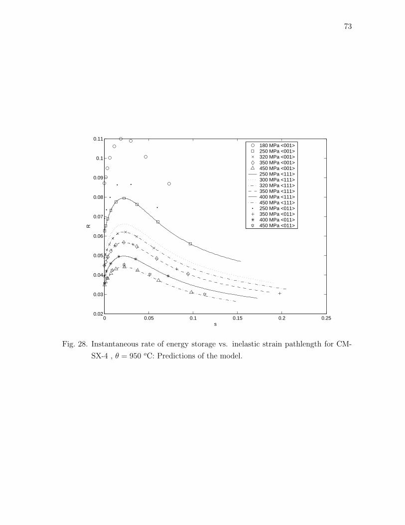
73
0 0.05 0.1 0.15 0.2 0.250.02
0.03
0.04
0.05
0.06
0.07
0.08
0.09
0.1
0.11
s
R
180 MPa <001>250 MPa <001>320 MPa <001>350 MPa <001>450 MPa <001>250 MPa <111>300 MPa <111>320 MPa <111>350 MPa <111>400 MPa <111>450 MPa <111>250 MPa <011>350 MPa <011>400 MPa <011>450 MPa <011>
Fig. 28. Instantaneous rate of energy storage vs. inelastic strain pathlength for CM-
SX-4 , θ = 950 oC: Predictions of the model.

74
CHAPTER V
IMPLEMENTATION IN FINITE ELEMENT SOFTWARE ABAQUS
The constitutive model that has been developed is implemented in finite element
software ABAQUS/STANDARD through a user subroutine (UMAT).
Table VIII. Schematic of the user subroutine UMAT in ABAQUS/STANDARD.
ABAQUS
(1) Solves the equilibrium equation at every time step (quasi-static problem).
(2) Large deformation analysis is carried out.
⇓ F(t), F(t + ∆t) ⇑ Fe(t + ∆t), T(t + ∆t)
⇓ Fe(t), T(t), s(t), G(t) ⇑ s(t + ∆t), G(t + ∆t)
UMAT
(1) Evaluates various quantities at time t + ∆t using their values at time t.
(2) Uses an implicit scheme based on backward difference (backward Euler method).
(3) Solves the resulting non-linear algebraic equation using Newton-Raphson method.
(4) Provide the jacobian J1 = ∂∆T∂∆E
,where E is the strain measure.
User MATerial or UMAT is the user subroutine that is written in FORTRAN
programming language and is used for incorporating the user defined material model
in ABAQUS/STANDARD. This feature makes it possible to define any constitutive
model of arbitrary complexity into ABAQUS. The user defined material models can
be used with any ABAQUS element type. The structure of UMAT also allows one to
incorporate multiple user materials at the same time. Table VIII shows the schematic
of the interaction between ABAQUS/STANDARD and UMAT for large deformation
analysis based on continuum formulation.
For the large deformation analysis based on continuum formulation, ABAQUS
75
sends, for each integration point, the values of total deformation gradient, F at the
current time t, the deformation gradient from the current natural configuration, Fe at
current time t, current value of the Cauchy stress, T and the state variables such as
s and G at the current time step. It also sends an estimate of the total deformation
gradient at the next time step (t + ∆t). The UMAT supplies the values of the state
variables such as s, Fe and G and Cauchy stress at time step t+∆t and return it back
to the ABAQUS. This process continues until the a converged solution is obtained
at time step t + ∆t. In estimating the value of total deformation gradient at time
t + ∆t, ABAQUS uses the value of the jacobian, J1 which is specified in the UMAT.
An exact definition of the consistent jacobian is necessary to ensure quadratic con-
vergence however the jacobian is often approximated in favor of a simpler algorithm
and computational speed. This may result in the loss of quadratic convergence. In
the current work, we have also used an approximate jacobian which is the same as
the elasticity matrix for a face centered cubic crystal.
A. Numerical scheme
In this section, the numerical scheme for the creep of superalloys loaded along the
<001> orientation is developed and implemented in UMAT. For this case, the rate
of dissipation can be assumed to be isotropic. However, the UMAT developed with
an isotropic rate of dissipation can not capture the anisotropy in the creep behav-
ior. Such an approach will enable the analysis of gas turbine blades loaded along the
<001> direction. This is especially relevant in the analysis of turbine blades because
the <001> orientation is the natural grain growth direction of single crystal superal-
loys and creep resistance of such components is the best along the <001> orientation.
The implementation of anisotropic creep in ABAQUS is completely different from the

76
isotropic case, since the way ABAQUS handles the anisotropic problem is entirely dif-
ferent from the isotropic case in that the specification of orientation of crystal lattice
in UMAT requires using additional user subroutines. Also, specifying the orientation
of crystal lattice using such user routines alters the way in which variables such as
stresses and strains are handled by UMAT. For example, when the orientation of crys-
tal lattice is specified using the user subroutine ORIENT in ABAQUS/STANDARD,
the stresses and strains components will be in the local basis (that is, the basis spec-
ifying the crystal axes) and this basis also rotates with the material in finite strain
analysis. A more general implementation of UMAT for anisotropic creep has not been
carried out in this work.
1. UMAT for creep along the <001> orientation
Let us now develop the numerical scheme based on implicit first order backward
difference formula (backward Euler method). For the sake of completeness let us now
list the equations describing the constitutive model. For the case when the rate of
dissipation is assumed to be isotropic, the equations describing the constitutive model
reduces to
Dp =s
h + 2k44s
(A− 1
3tr(A)I−α
),
:=s
h + 2k44sA .
(5.1)
Using the definition for s (=√
Dp ·Dp), we can get an explicit expression for s:
s =1
2k44
(√A · A− h
). (5.2)
77
Using Eqs. (5.1) and (5.2), equations for the evolution of inelastic stored energy and
backstress (Eqs. (3.20) and (3.22), respectively) reduce to
˙ψ =1
ρ
(h +
α · A√A · A
)s . (5.3)
α =(ρψ2
A√A · A
− ηα)s , (5.4)
Discreatizing Eqs (5.2), (5.3) and (5.4) using first order backward difference, we
arrive at the following algebraic non-linear equations.
f1 := t+∆ts− ts− ∆t
2t+∆tk44
(√t+∆tA · t+∆tA− t+∆th
)= 0 , (5.5)
f2 := t+∆tψ− tψ− (t+∆ts− ts)
ρ
(t+∆th− ∆tt+∆tα · t+∆tA
t+∆th∆t + 2t+∆tk44(t+∆ts− ts)
)= 0 , (5.6)
f3 := t+∆tα− tα + ηt+∆tα(t+∆ts− ts)− ρψ2∆tt+∆tA(t+∆ts− ts)t+∆th∆t + 2t+∆tk44(t+∆ts− ts)
= 0 . (5.7)
Eqs (5.5), (5.6) and (5.7) are set of non-linear algebraic equations which need to be
solved for t+∆ts, t+∆tψ and t+∆tα.
The set of equations (5.5)-(5.7) is solved using Newton-Raphson method. For
the sake of convenience, the second order symmetric tensors are written as a column
vector (Voigt notation). Lets define the vector H and Y such that
[H] =
f1
f2
f3
, [Y] =
t+∆ts
t+∆tψ
t+∆tα
. (5.8)
The equation H(Y) = 0 is solved for Y in order to get the solution using Newton-
Raphson scheme:
Yk+1 = Yk − [J]−1H(Yk) , (5.9)

78
where
J =
∂f1
∂s∂f1
∂ψ
∂f1
∂α∂f2
∂s∂f2
∂ψ
∂f3
∂α
∂f3∂s
∂f3∂ψ
∂f3∂α
, (5.10)
and k is the iteration number. The solution at time t for the variables s, G and α is
used as the initial guess for the Newton-Raphson scheme in order to find their values
at time step t + ∆t.
The derivatives appearing in the jacobian are evaluated as follows:
∂f1
∂s= 1− ∆t
2
∂(k44)−1
∂s
(√A · A− h
)+
ρ∆t(k44)−1
2(ψ1a
′′ + ψ1ηa′) , (5.11a)
∂f1
∂ψ= −ρη∆t
(k44)−1
2, (5.11b)
∂f1
∂α=
∆t(k44)−1
2
A√A · A
, (5.11c)
∂f2
∂s=− ∂h
∂s
(s− ts
ρ
)− h
ρ− 1
ρ
(∆tα · A
h∆t + 2k44(s− ts)
)
+1
ρ
(∆t)2(s− ts)α · A(h∆t + 2k44(s− ts))2
(∂h
∂s+
2k44
∆t+
2(s− ts)
∆t
∂k44
∂s
),
(5.11d)
∂f2
∂ψ= 1 + η(s− ts)
(1− (∆t)2(s− ts)α · A
(h∆t + 2k44(s− ts))2
), (5.11e)
∂f2
∂α= −(s− ts)
ρ
(A−α
h∆t + 2k44(s− ts)
), (5.11f)
∂f3∂s
=− ρψ2∆t
(A
h∆t + 2k44(s− ts)
)
+ρψ2(∆t)2(s− ts)A
(h∆t + 2k44(s− ts))2
(∂h
∂s+
2k44
∆t+
2(s− ts)
∆t
∂k44
∂s
),
(5.11g)
∂f3
∂ψ= − ρ2ηψ2(∆t)2(s− ts)A
(h∆t + 2k44(s− ts))2, (5.11h)
79
∂f3∂α
=
(1 +
ρψ2∆t(s− ts)
h∆t + 2k44(s− ts)+ η(s− ts)
)I4 , (5.11i)
where
a′(s) = β2α1e−α1s , (5.12a)
a′′(s) = −β2α21e−α1s , (5.12b)
∂(k44)−1
∂s= β1e
κ1pa′e−α2s − α2β1aeκ1pe−α2s + β3α3eκ2peα3s , (5.12c)
∂k44
∂s= −k2
44
(β1e
κ1pa′e−α2s − α2β1aeκ1pe−α2s + β3α3eκ2peα3s
), (5.12d)
p =1
3tr(A) , (5.12e)
and a(s) and h are as defined in equations (3.19) and (3.20), respectively. All the
quantities that appear in the terms which constitute the jacobian are determined at
the iteration level k.
2. Validation of UMAT for creep along the <001> orientation
The numerical scheme developed in the previous section is implemented in UMAT
to study the creep behavior of single crystal superalloys loaded along the <001>
orientation. The UMAT is validated by using it to obtain the results already obtained
in previous sections using the semi-inverse approach. The results obtained through
the UMAT is compared with the results obtained using the semi-inverse approach
and the experimental results. Figs. 29, 30 and 31 show a comparison of strain versus
time curves for loading along <001> orientation at temperatures θ = 750, 982 and
1000 oC obtained using the UMAT and the semi-inverse method and experimental
results. Figs. 32, 33 and 34 show a comparison for the inelastic stored energy at
temperatures θ = 750, 982 and 1000 oC. A similar comparison is shown for third
component of the backstress tensor in Figs. 35, 36 and 37. Figs. 38, 39 and 40 show
the same comparison for instantaneous rate of energy storage.

80
Abaqus 735 MPaAbaqus 800 MPaExperiments 735 MPaExperiments 800 MPaMatlab 735 MPaMatlab 800 MPa
Fig. 29. Strain vs. time for CMSX-4 for loading along the <001> orientation,
θ = 750 oC: Comparison of the results obtained from User Material in
ABAQUS with results obtained in MATLAB and experimental results of Svo-
boda and Lucas [90] and Henderson and Lindblom [32].

81
Abaqus 167.5 MPaAbaqus 206.9 MPaAbaqus 248.2 MPaExperiment 167.5 MPaExperiment 206.9 MPaExperiment 248.2 MPaMatlab 167.5 MPaMatlab 206.9 MPaMatlab 248.2 MPa
Fig. 30. Strain vs. time for CMSX-4 for loading along the <001> orientation,
θ = 982 oC: Comparison of the results obtained from User Material in
ABAQUS with results obtained in MATLAB and experimental results of Svo-
boda and Lucas [90] and Henderson and Lindblom [32].

82
Abaqus 150 MPaAbaqus 200 MPaExperiment 150 MPaExperiment 200 MPaMatlab 150 MPaMatlab 200 MPa
Fig. 31. Strain vs. time for CMSX-4 for loading along the <001> orientation,
θ = 1000 oC: Comparison of the results obtained from User Material in
ABAQUS with results obtained in MATLAB and experimental results of Svo-
boda and Lucas [90] and Henderson and Lindblom [32].

83
Abaqus 735 MPaAbaqus 800 MPaMatlab 735 MPaMatlab 800 MPa
Fig. 32. Inelastic stored energy vs. inelastic strain pathlength for CMSX-4 for loading
along the <001> orientation, θ = 750 oC: Comparison of the results obtained
from User Material in ABAQUS with results obtained in MATLAB.
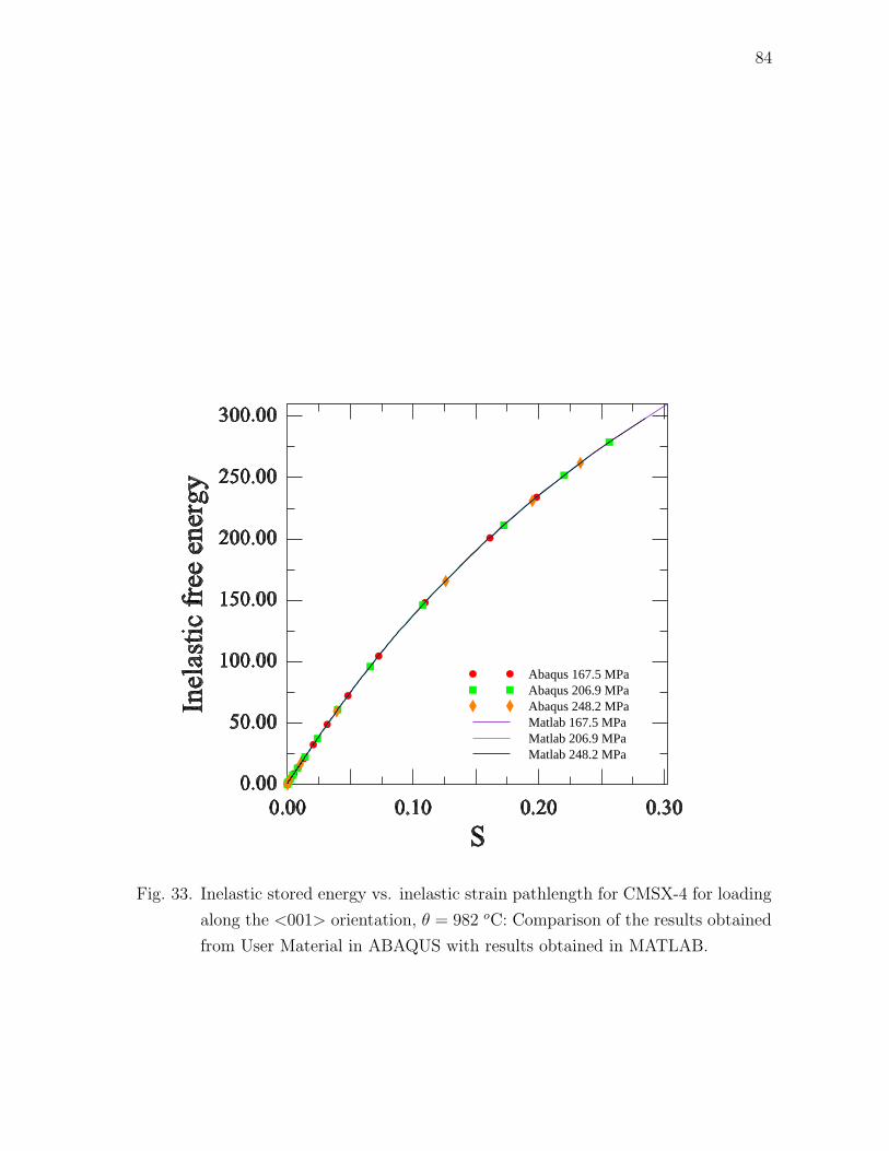
84
Abaqus 167.5 MPaAbaqus 206.9 MPaAbaqus 248.2 MPaMatlab 167.5 MPaMatlab 206.9 MPaMatlab 248.2 MPa
Fig. 33. Inelastic stored energy vs. inelastic strain pathlength for CMSX-4 for loading
along the <001> orientation, θ = 982 oC: Comparison of the results obtained
from User Material in ABAQUS with results obtained in MATLAB.

85
Abaqus 150 MPaAbaqus 200 MPaMatlab 150 MPaMatlab 200 MPa
Fig. 34. Inelastic stored energy vs. inelastic strain pathlength for CMSX-4 for loading
along the <001> orientation, θ = 1000 oC: Comparison of the results obtained
from User Material in ABAQUS with results obtained in MATLAB.

86
Fig. 35. Third component of backstress vs. inelastic strain pathlength for CMSX-4,
θ = 750 oC: Comparison of the results obtained from User Material in
ABAQUS with results obtained in MATLAB.
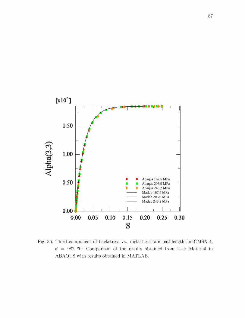
87
Abaqus 167.5 MPaAbaqus 206.9 MPaAbaqus 248.2 MPaMatlab 167.5 MPaMatlab 206.9 MPaMatlab 248.2 MPa
Fig. 36. Third component of backstress vs. inelastic strain pathlength for CMSX-4,
θ = 982 oC: Comparison of the results obtained from User Material in
ABAQUS with results obtained in MATLAB.
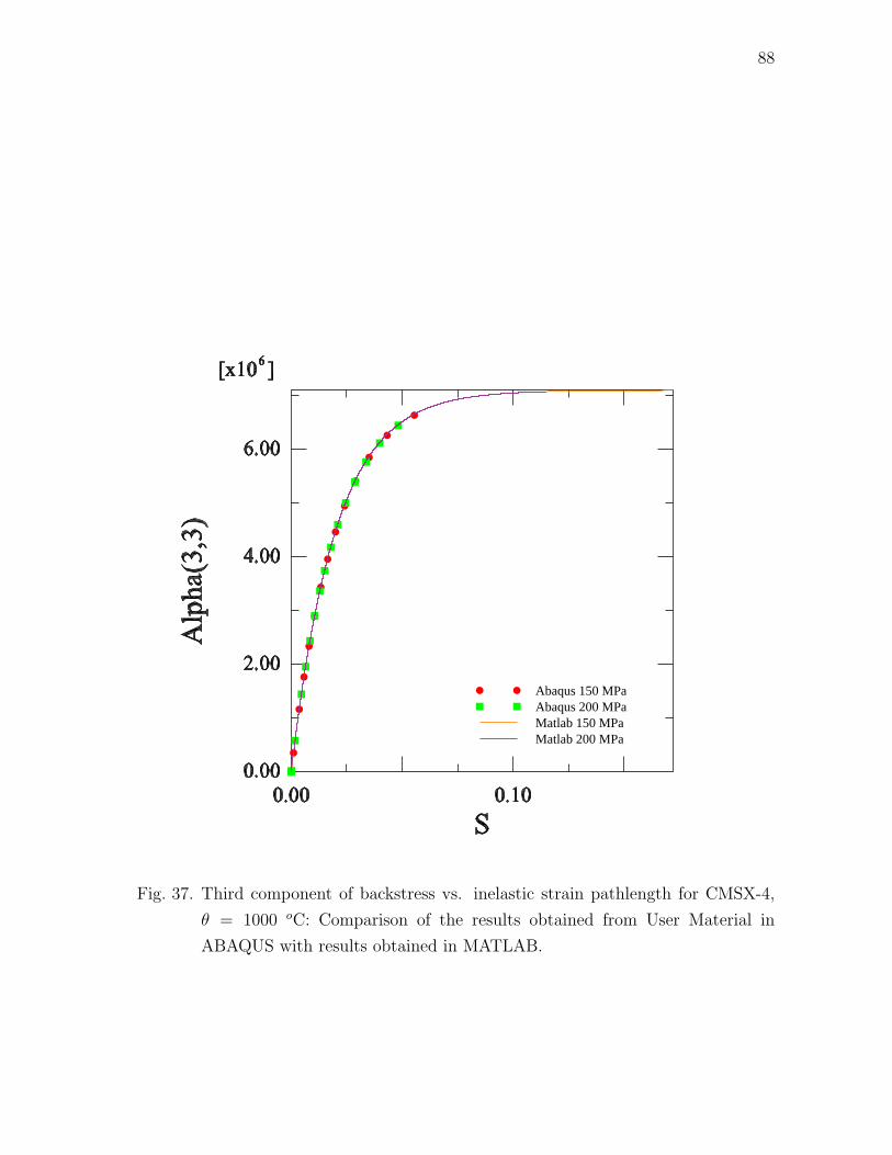
88
Abaqus 150 MPaAbaqus 200 MPaMatlab 150 MPaMatlab 200 MPa
Fig. 37. Third component of backstress vs. inelastic strain pathlength for CMSX-4,
θ = 1000 oC: Comparison of the results obtained from User Material in
ABAQUS with results obtained in MATLAB.

89
Abaqus 735 MPaAbaqus 800 MPaMatlab 735 MPaMatlab 800 MPa
Fig. 38. Instantaneous rate of energy storage vs. inelastic strain pathlength for CM-
SX-4 for loading along the <001> orientation, θ = 750 oC: Comparison of
the results obtained from User Material in ABAQUS with results obtained in
MATLAB.
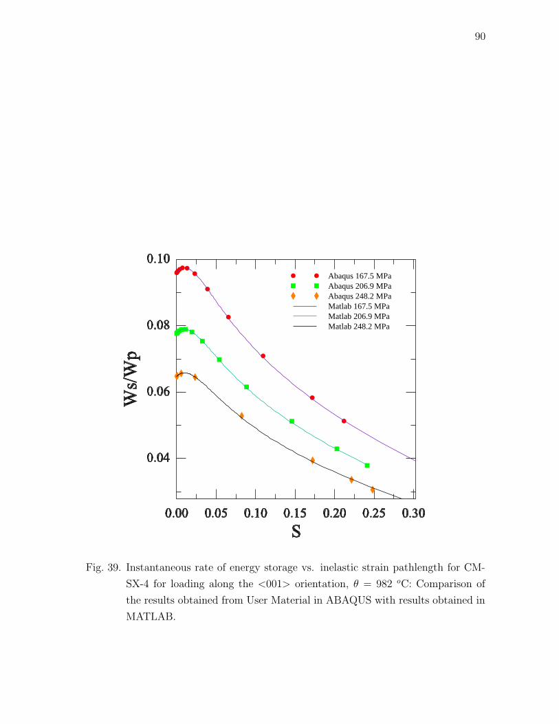
90
Abaqus 167.5 MPaAbaqus 206.9 MPaAbaqus 248.2 MPaMatlab 167.5 MPaMatlab 206.9 MPaMatlab 248.2 MPa
Fig. 39. Instantaneous rate of energy storage vs. inelastic strain pathlength for CM-
SX-4 for loading along the <001> orientation, θ = 982 oC: Comparison of
the results obtained from User Material in ABAQUS with results obtained in
MATLAB.

91
Abaqus 150 MPaAbaqus 200 MPaMatlab 150 MPaMatlab 200 MPa
Fig. 40. Instantaneous rate of energy storage vs. inelastic strain pathlength for CM-
SX-4 for loading along the <001> orientation, θ = 1000 oC: Comparison of
the results obtained from User Material in ABAQUS with results obtained in
MATLAB.

92
CHAPTER VI
A THERMOMECHANICAL MODEL FOR THE CREEP OF SUPERALLOYS
In this chapter, a thermomechanical model for creep of single crystal superalloys will
be developed. Although, complete constitutive prescriptions for stored energy and
rate of dissipation function is not provided, the outline of such a model is delineated.
An evolution equation for the evolution of rafts with creep strain is also incorporated
within the thermodynamical framework.
A. Development of non-isothermal model
Let us now again start with the reduced dissipation equation (Eq. (3.2)):
T · L− ρψ − ρηθ = ζ ≥ 0 , (6.1)
wherein the term associated with the rate of dissipation due to conduction (−q·grad(θ)θ
)
has already been additively split from the rate of dissipation term on the right hand
side.
We will assume that the Helmholtz potential for a single crystal superalloy is of
the form
ψ(Fκp(t),G, ϕ, θ) = ψ(θ) + ψ(Fκp(t)
, θ) + ψ(G, ϕ, θ) , (6.2)
where ϕ is a measure of the extent of rafting. Although there is no robust way of
measuring the extent of rafting in modern single crystal superalloys, experiments
carried out by Matan et al. [48] seems to be the only effort towards this goal. Matan
et al. [48] used a stereological procedure utilizing techniques based on digital image
analysis to characterize the extent of rafting.

93
The form for the ψ(θ) is assumed to be
ψ(θ) = bo − 1
2b2(θ − θo)
2 , (6.3)
and the form for the elastic stored energy for a crystal having cubic symmetry is given
by
ψ =1
2ρ
c12(θ)(tr Eκp(t)
)2 + 2c44(θ)(tr E2κp(t)
) + (c11(θ)− c12(θ)− 2c44(θ))
((a · Eκp(t)
a)2 + (b · Eκp(t)b)2 + (c · Eκp(t)
c)2)
− b1(tr Eκp(t))(θ − θo) .
(6.4)
ψ(G, ϕ, θ) denoted the inelastic stored energy which is a function of temperature,
inelastic strain and the extent of rafting.
Substituting the form for the stored energy into reduced dissipation equation
(Eq. (6.1)) and collecting like terms will lead to
(TF−T
κp(t)− ρ
∂ψ
∂Fκp(t)
)· Fκp(t)
+
(FT
κp(t)TF−T
κp(t)− ∂ψ
∂GGT
)· Lp
−ρ
(η +
∂ψ
∂θ+
∂ψ
∂θ+
∂ψ
∂θ
)θ − ρ
∂ψ
∂ϕϕ = ζ .
(6.5)
We are only looking for sufficient conditions to satisfy Eq. (6.5). Towards such
a goal, we will assume the Cauchy stress to be of the form given by
T = ρ∂ψ
∂Fκp(t)
FTκp(t)
= ρFκp(t)
∂ψ
∂Eκp(t)
FTκp(t)
=(c12(θ)(tr Eκp(t)
)− ρb1(θ − θo))Fκp(t)
FTκp(t)
+ 2c44(θ)Fκp(t)Eκp(t)
FTκp(t)
+ (c11(θ)− c12(θ)− 2c44(θ))Fκp(t)(NEκp(t)
)FTκp(t)
,
(6.6)
where fourth order tensor N has the form
Nijkl = aiajakal + bibjbkbl + cicjckcl . (6.7)
ai, bi and ci are the components of the orthogonal unit vectors a, b and c along
94
the crystal axes. It should be noted here that Eq. (6.6) when linearized under the
assumption of small elastic strain gives the usual relation for linear thermoelasticity:
T ≈ c12(θ)(tr εκp(t))I + 2c44(θ)εκp(t)
+ (c11(θ)− c12(θ)− 2c44(θ))(N εκp(t))
−ρb1(θ − θo)I ,
(6.8)
where εκp(t)is the linearized strain tensor from the natural configuration κp(t).
We also suppose that
η = −(
∂ψ
∂θ+
∂ψ
∂θ+
∂ψ
∂θ
)
= b1(tr Eκp(t)) + b2(θ − θo)− 1
2ρ
co12(tr Eκp(t)
)2 + 2co44(tr E2
κp(t))
+ (co11 − co
12 − 2co44)
((a · Eκp(t)
a)2 + (b · Eκp(t)b)2 + (c · Eκp(t)
c)2)
− ∂ψ
∂θ,
(6.9)
where we have assumed, following the experimental observations of Sieborger et al.
[88] that the elastic constants c11, c12 and c44 depend on temperature in a linear
fashion:
c11(θ) = co11θ + c1
11 , c12(θ) = co12θ + c1
12 , c44(θ) = co44θ + c1
44 . (6.10)
Substituting Eqs. (6.6) and (6.9) into Eq. (6.5) will lead us to
(FT
κp(t)TF−T
κp(t)− ∂ψ
∂GGT
)· Lp − ρ
∂ψ
∂ϕϕ = ζ . (6.11)
We will assume that the rate of dissipation ζ can be split into two parts. The
first part ζm relates to the entropy production due to mechanical working while the
other part ζR is the entropy production due to rafting, i.e.,
ζ(G,Lp, ϕ, ϕ, θ) = ζm(G,Lp, ϕ, θ) + ζR(G,Lp, ϕ, ϕ, θ) . (6.12)
Inserting Eq. (6.12) into Eq. (6.11) and appealing to sufficiency condition again, we

95
arrive at
A · Lp = ζm(G,Lp, ϕ, θ) ,
A :=
(FT
κp(t)TF−T
κp(t)− ∂ψ
∂GGT
),
(6.13)
and
−ρ∂ψ
∂ϕϕ = ζR(G,Lp, ϕ, ϕ, θ) . (6.14)
Equation (6.14) is the equation governing the rafting kinetics.
We will further assume that the rate of dissipation due to mechanical working
takes the following form:
ζm = ζ1m + ζ2
m
= Dp ·KDp + η2Wp ·Wp ,
(6.15)
Combining Eq. (6.13) with Eq. (6.15) lead us to
Asym ·Dp = ζ1m ,
Askew ·Wp = ζ2m ,
(6.16)
where sym and skew denotes the symmetric and skew parts of the tensor A.
Maximizing the rate of dissipation subject to the constraint tr(Dp) = 0 lead us
to following equations for Dp and Wp:
Dp = K−1
(Asym − tr(K−1Asym)
tr(K−1I)I
),
Wp =Askew
η2
.
(6.17)
Equations (6.17) and (6.14) give us the complete set of equations for determining the
evolution of natural configurations.
The framework developed in this chapter is general enough to develop models
to describe the thermomechanical response of single crystal superalloys. A equation
96
describing the rafting kinetics has also been incorporated from a thermodynamical
perspective. Forms for the rate of dissipation associated with rafting and the inelastic
stored energy as a function of inelastic strain, temperature and extent of rafting need
to be developed to develop specific models.

97
CHAPTER VII
CONCLUSIONS
A. Summary
The current work was focussed on developing a constitutive model for describing the
creep of single crystal superalloys at high temperatures in the range of 700 oC to 1000
oC with emphasis on microstructure, dissipation of energy and material symmetry.
The framework that has been used is general enough in that a plethora of constitu-
tive models can be developed to describe a diverse range of material behavior. The
framework is rooted in a robust thermodynamical setting and hence it is the choice to
model the high temperature creep behavior of single crystal superalloys. Some of the
salient features of the constitutive model and the modeling approach that has been
used and the major accomplishments are as follows:
1. The constitutive model that has been developed is within a thermodynamical
framework that has been put in place to describe the mechanics of bodies ca-
pable of existing in multiple stress free configurations or natural configurations.
The framework is built on the idea of evolving natural configurations and max-
imization of the rate of dissipation. Specific choice for stored energy function
and the rate of dissipation function give rise to different constitutive models
which capture diverse range of material behavior. The constitutive model com-
plies with the second law of thermodynamics through the requirement that the
rate of entropy production be non negative.
2. The framework recognizes the fact that single crystals are not simple materials
in the sense of Noll and takes into account the appropriate symmetry of single
crystals and its evolution. For the case of single crystals, the symmetry remains

98
the same as the crystal is sheared since the underlying crystal lattice remains
the same. This rules out modeling single crystals using the theory of simple
materials. The current framework fills this lacunae and takes into account
the fact that the symmetry of single crystals remains the same as the crystal
undergoes inelastic deformations.
3. The current approach has definitive advantage over theories based on the notion
of directors, which has certain inherent difficulties such as introduction of new
balance laws containing terms which are not physically motivated. Moreover,
there are difficulties with regard to specifying boundary conditions for quantities
such as directors. Current approach appeals to thermodynamical quantities
such as stored energy and rate of dissipation functions which can be readily
measured using experiments based on calorimetry. No additional balance laws
need to be introduced here and ideas associated with dislocation motion, which
are very physical, are used.
4. Appropriate forms for the stored energy and the rate of dissipation function are
developed in order to describe the creep behavior of single crystal superalloys.
The form for the stored energy has two parts, one due to the elastic part of the
deformation and the other due to the inelastic part. The form for the inelas-
tic stored energy captures the part of mechanical work that is trapped in the
dislocation networks. As pointed out earlier, models due to Lee [40], Brown et
al. [5] and Mason et al. [46] account for this kind of energy storage mechanism
in the body by multiplying the “plastic work” by an ad hoc factor whose value
is approximately 0.8. The current work accounts for this energy storage mech-
anism explicitly and adopts the rigorous ideas developed by Mollica et al. [50].
Such an approach is especially relevant to single crystal superalloys which are

99
strengthened by the presence of various alloying elements (solid solution hard-
ening) and other hardening phases such as γ′ phase (precipitation hardening).
A form for the rate of dissipation function is developed based on the idea of
energy dissipation during a thermo-mechanical process through the movement
of dislocations which are mobile.
5. The form for elastic stored energy reflects the fact that the elastic response
exhibits cubic symmetry. The rate of dissipation function is chosen to be
anisotropic, in that it reflects invariance to transformations that belong to the
cubic symmetry group. Such a choice captures the anisotropy in the creep be-
havior of single crystal superalloys. Also, the symmetry of the single crystal
does not change as the natural configuration is evolving.
6. The results of the model corroborate well with the experimental data for a range
of temperatures and different loading orientations. The model needs to be cor-
roborated with experimental data for the <001> and the <111> orientations.
Once corroborated, the model predicts the creep strain versus time behavior for
other orientations. One such comparison at 950 oC showed that the predictions
of the model are reasonably close to the experimental results.
B. Recommendations for future work
The current work was first of its kind wherein creep behavior of single crystal superal-
loys was modeled within a three dimensional continuum mechanics based thermody-
namical framework. While the model captures the creep deformation of single crystal
superalloys reasonably well, there is a need to utilize the model to solve problems in
a wide range of operating conditions which gas turbine blades are subject to.
Following are specific recommendations to improve or utilize the model for solving

100
various problems:
1. The model is used to describe the creep strain versus time behavior for different
temperatures and loading orientations such as the <001>, <111> and <011>
orientations. In such orientations, there is no associated rotation of crystal lat-
tice. The model should be used to predict the creep strain versus time behavior
for arbitrary orientations. Such results are of interest because manufacturing
limitations does not allow the specimen to be perfectly oriented along the <001>
orientation which is the desired orientation. A study of creep behavior of single
crystal superalloys as a function of small misorientations away from the <001>
orientation needs to be carried out. Since the deformation is such cases is three
dimensional, solution using a semi-inverse method seems infeasible. However,
the user subroutine developed herein can be used to carry out such an analysis.
2. The components such as gas turbine blades are manufactured in the <001>
orientation since <001> is the natural grain growth direction for single crystal
superalloys. The current user subroutine can be used to study the creep response
of gas turbine blades loaded along the <001> orientation. These components
usually have a complex shape with lot of intricate cooling channels built in to
facilitate cooling of components. Such problems can be studied in commercial
finite element software ABAQUS using the user defined material subroutine
formulated in the current work. Also an analysis can be carried out when the
loading condition is more complicated.
3. The constitutive model that has been developed in the current work is an
isothermal model. The material parameters that appear in the model need
to be changed with temperature. The motivation for such a constitutive model
is the fact that the creep experiments are carried out at constant temperature.

101
While we have presented a general thermo-mechanical model for capturing the
creep behavior as a function of temperature, orientation and applied stress, we
have not corroborated the model. A corroboration of such a thermo-mechanical
model will lead to a unified model which can capture the creep behavior as a
function of temperature, loading orientation and applied stress with a single set
of material parameters. Such a thermo-mechanical model can also be incorpo-
rated in ABAQUS through a user defined material subroutine to enable three
dimensional thermo-inelastic analysis of gas turbine blades.
4. The current model captures the behavior of single crystal superalloys reasonably
well in the temperature range 700 oC to 1000 oC. The effect of high temperature
rafting has not been explicitly incorporated by specifying an evolution equation
for rafting. There are several road blocks towards such a goal. One needs to have
a credible way to quantify the amount of rafting that has taken place, something
which has not been done. The other limitation is that the effect rafting has on
dislocation motion is not clearly understood although the rule of thumb is that
at temperatures beyond 1000 oC, rafting improves the creep strength in single
crystal nickel based superalloys. The current thermodynamical framework is
well suited to come up with an evolution equation for rafting and its effect on
dislocation motion. Although we have presented a theoretical framework to
incorporate the effect of rafting and the evolution of rafts, specific models need
to be developed.
102
REFERENCES
[1] R. J. Asaro, “Micromechanics of cyrstals and polycrystals,” Advances in Applied
Mechanics, vol. 23, pp. 1–115, 1983.
[2] A. Bertram and J. Olschewski, “Anisotropic creep modelling of the single crystal
superalloy SRR99,” Computational Materials Science, vol. 5, pp. 12–16, 1996.
[3] M. B. Bever, D. L. Holt, and A. L. Tichener, “Stored energy of cold work,”
Progress in Materials Science, vol. 17, pp. 5–177, 1972.
[4] B. A. Bilby, “Continous distribution of dislocations,” in Solid Mechanics,
I. Sneddon and R. Hill, Eds. Amsterdam: North-Hollands, 1960.
[5] S. B. Brown, K. H. Kim, and L. Anand, “An internal variable constitutive
model for hotworking of metals,” International Journal of Plasticity, vol. 5, pp.
95–130, 1989.
[6] G. Bruno, B. Schonfeld, and G. Kostorz, “Lattice misfit in CMSX-4 like Nickel-
base superalloys and its temperature dependence,” Zeitschrift Fur Metallkunde,
vol. 94, no. 1, pp. 12–18, Jan. 2003.
[7] J. Y. Buffiere and M. Ignat, “A dislocation based criterion for the raft forma-
tion in nickel-based superalloys single-crystals,” Acta Metallurgica et Materialia,
vol. 43, no. 5, pp. 1791–1797, May 1995.
[8] P. Caron and T. Khan, “Improvement of creep strength in a Nickel-base single-
crystal super-alloy by heat-treatment,” Materials Science and Engineering,
vol. 61, no. 2, pp. 173–184, 1983.
103
[9] P. Caron, T. Khan, and Y. G. Nakagawa, “Effect of orientation on the interme-
diate temperature creep behavior of Ni-base single crystal superalloys,” Scripta
Metallurgica, vol. 20, pp. 499–502, 1986.
[10] C. Carry and J. L. Strudel, “Apparent and effective creep parameters in single-
crystals of a Nickel-base superalloy .1. incubation period,” Acta Metallurgica,
vol. 25, no. 7, pp. 767–777, 1977.
[11] C. Carry and J. L. Strudel, “Apparent and effective creep parameters in single-
crystals of a Nickel-base super-alloy .2. secondary creep,” Acta Metallurgica,
vol. 26, no. 5, pp. 859–870, 1978.
[12] J. L. Chaboche, “Time-independent constitutive theories for cyclic plasticity,”
International Journal of Plasticity, vol. 2, no. 2, pp. 149–188, 1986.
[13] J. L. Chaboche, “Cyclic viscoplastic constitutive equations. part i: A thermo-
dynamically consistent formulation,” Journal of Applied Mechanics, vol. 60, pp.
813–821, 1993.
[14] J. L. Chaboche, “Cyclic viscoplastic constitutive equations. part ii: Stored en-
ergy - comparison between models and experiments,” Journal of Applied Me-
chanics, vol. 60, pp. 822–828, 1993.
[15] J. C. Chang and S. M. Allen, “Elastic energy changes accompanying γ′ rafting
in Nickel-base superalloys,” Journal of Materials Research, vol. 6, no. 9, pp.
1843–1855, Sep. 1991.
[16] A. Coujou, M. Benyoucef, M. Legros, and N. Clement, “Role of the γ/γ′ in-
terface on the mechanical properties of single crystals Nickel base superalloys,”
Solid State Phenomena, vol. 60, pp. 185–200, 1998.
104
[17] M. J. Donachie and S. J. Donachie, Superalloys. Materials Park, Ohio: ASM
International, 2002.
[18] M. Durand-Charre, The Microstructure of Superalloys. Amsterdam: Gordon
and Breach Science Publishers, 1997.
[19] B. F. Dyson, “Creep and fracture of metals: mechanisms and mechanics,” Revue
de Physique Appliquee, vol. 23, pp. 605–613, 1988.
[20] B. F. Dyson and M. Mclean, “Particle-coarsening, σo and tertiary creep,” Acta
Metallurgica, vol. 31, pp. 17–27, 1983.
[21] C. Eckart, “The thermodynamics of irreversible processes. iv. the theory of
elasticity and anelasticity,” Physical Review, vol. 73, pp. 373–382, 1948.
[22] J. D. Eshelby, “The continuum theory of lattice defects,” in Solid State Physics,
F. Seitz and D. Turnbull, Eds. New York: Academic Press, 1956.
[23] J. A. Ewing and W. Rosenhain, “The crystalling structure of metals,” Philo-
sophical Transactions of the Royal Society, London. Series A, vol. 193, pp.
353–375, 1920.
[24] J. Gayda and R. A. Mackay, “Analysis of γ′ shape changes in a single-crystal
Ni-base superalloy,” Scripta Metallurgica, vol. 23, no. 11, pp. 1835–1838, Nov.
1989.
[25] J. Gayda and D. J. Srolovitz, “A monte-carlo-finite element model for strain-
energy controlled microstructural evolution - rafting in superalloys,” Acta Met-
allurgica, vol. 37, no. 2, pp. 641–650, Feb. 1989.
105
[26] R. N. Ghosh, R. V. Curtis, and M. Mclean, “Creep deformation of single crys-
tal superalloys-modeling the crystallographic anisotropy,” Acta Metallurgica et
Materialia, vol. 38, no. 10, pp. 1977–1992, Oct. 1990.
[27] R. N. Ghosh and M. Mclean, “Modeling the orientation dependence of tertiary
creep in single crystal superalloy,” Scripta Metallurgica, vol. 23, pp. 1301–1306,
1989.
[28] J. J. Gilman, Micromechanics of Flow in Solids. New York: McGraw-Hill,
1969.
[29] A. E. Green and P. M. Naghdi, “On thermodynamics and the nature of the
second law,” Proceedings of the Royal Society of London Series A, vol. 357, pp.
253–270, 1977.
[30] S. S. K. Gunturi, D. W. Maclachlan, and D. M. Knowles, “Anisotropic creep
in CMSX-4 in orientations distant from <001>,” Materials Science and Engi-
neering, vol. A289, pp. 289–289, 2000.
[31] K. S. Havner, Finite Plastic deformation of crystalline solids. Cambridge:
Cambridge University Press, 1992.
[32] P. J. Henderson and J. Lindblom, “High temperature creep in a <001> single
crystal Nickel-base superalloy,” Scripta Materialia, vol. 37, no. 4, pp. 491–496,
1997.
[33] M. Ignat, J. Y. Buffiere, and J. M. Chaix, “Microstructures induced by a stress
gradient in a Nickel-based superalloy,” Acta Metallurgica et Materialia, vol. 41,
no. 3, pp. 855–862, Mar. 1993.

106
[34] W. C. Johnson, “On the elastic stabilization of precipitates against coarsening
under applied load,” Acta Metallurgica, vol. 32, no. 3, pp. 465–475, 1984.
[35] W. C. Johnson, M. B. Berkenpas, and D. E. Laughlin, “Precipitate shape
transitions during coarsening under uniaxial-stress,” Acta Metallurgica, vol. 36,
no. 12, pp. 3149–3162, 1988.
[36] M. Kamlah and P. Haupt, “On the macroscopic description of stored energy
and self heating during plastic deformation,” International Journal of Plasticity,
vol. 13, no. 10, pp. 893–911, 1998.
[37] B. H. Kear and B. J. Piearcey, “Tensile and creep properties of single crystals of
nickel-base superalloy MAR-M200,” Transactions of the Metallurgical Society
of AIME, vol. 239, no. 8, pp. 1209–1215, 1967.
[38] K. Kondo, “On the analytical and physical foundation of the theory of dis-
locations and yielding by the differential geometry of continua,” International
Journal of Engineering Science, vol. 2, pp. 219–251, 1964.
[39] E. Kroner, “Alleganeine kontinuumstheorie der verzetsmugen and eigenspan-
nuugen,” Archive for Rational Mechanics and Analysis, vol. 4, pp. 273–334,
1960.
[40] E. H. Lee, “Elastic-plastic deformation at finite strains,” Journal of Applied
Mechanics, vol. 36, pp. 1–6, 1969.
[41] G. R. Leverant and H. B. Kear, “The mechanism of creep in gamma prime
precipitation-hardened nickel-base alloys at intermediate temperatures,” Met-
allurgical Transactions, vol. 1, no. 2, pp. 491–498, 1970.
107
[42] G. R. Leverant, H. B. Kear, and J. M. Oblak, “Creep of precipitation-hardened
Nickel-base alloy single-crystals at high-temperatures,” Metallurgical Transac-
tions, vol. 4, no. 1, pp. 335–362, 1973.
[43] R. A. MacKay and R. D. Maier, “The influence of orientation on the stress rup-
ture properties of nickel-base superalloy single crystals,” Metallurgical Trans-
actions A, vol. 13A, pp. 1747–1754, 1982.
[44] D. W. Maclachlan and D. M. Knowles, “The effect of material behaviour on the
analysis of single crystal turbine blades: Part I-material model,” Fatigue and
Fracture of Engineering Materials and Structures, vol. 25, pp. 385–398, 2002.
[45] D. W. Maclachlan, L. W. Wright, S. Gunturi, and D. M. Knowles, “Constitutive
modelling of anisotropic creep deformation in single crystal blade alloys SRR99
and CMSX-4,” International Journal of Plasticity, vol. 17, pp. 441–467, 2001.
[46] J. J. Mason, A. J. Rosakis, and G. Ravichandran, “On the strain and strain rate
dependence of the fraction of plastic work converted to heat: an experimental
study using high speed infrared detectors and the Kolsky bar,” Mechanics of
Materials, vol. 17, pp. 135–145, 1994.
[47] N. Matan, D. C. Cox, P. Carter, M. A. Rist, C. M. F. Rae, and R. C. Reed,
“Creep of CMSX-4 superalloy single crystals: Effects of misorientation and
temperature,” Acta Materialia, vol. 47, no. 5, pp. 1549–1563, 1999.
[48] N. Matan, D. C. Cox, C. M. F. Rae, and R. C. Reed, “On the kinetics of
rafting in CMSX-4 superalloy single crystals,” Acta Materialia, vol. 47, no. 7,
pp. 2031–2045, 1999.

108
[49] M. McLean, Directionally Solidified Materials for High Temperature Service.
London: The Metals Society, 1983.
[50] F. Mollica, K. R. Rajagopal, and A. R. Srinivasa, “The inelastic behavior of
metals subject to loading reversal,” International Journal of Plasticity, vol. 17,
pp. 1119–1146, 2001.
[51] J. Murali Krishnan and K. R. Rajagopal, “Thermodynamic framework for the
constitutive modeling of asphalt concrete: Theory and applications,” Journal
of Materials in Civil Engineering, vol. 16, no. 2, pp. 155–166, 2004.
[52] F. R. N. Nabarro, Theory of Crystal Dislocations. New York: Dover Publica-
tions, 1987.
[53] F. R. N. Nabarro, “The superiority of superalloys,” Materials Science and En-
gineering A, vol. 184, no. 2, pp. 167–171, Aug. 1994.
[54] F. R. N. Nabarro, C. M. Cress, and P. Kotschy, “Thermodynamic driving force
for rafting in superalloys,” Acta Materialia, vol. 44, no. 8, pp. 3189–3198, Aug.
1996.
[55] F. R. N. Nabarro and H. L. De Villers, The Physics of Creep. London: Tylor
& Francis, 1995.
[56] P. M. Naghdi and A. R. Srinivasa, “A dynamical theory of structured solids. i.
Basic developments,” Philosophical Transactions of the Royal Society, London.
Series A, vol. 345, pp. 425–458, 1993.
[57] P. M. Naghdi and A. R. Srinivasa, “Characterization of dislocations and their
influence on plastic deformation in single crystals,” International Journal of
Engineering Science, vol. 32, no. 7, pp. 1157–1182, Jul. 1994.
109
[58] M. V. Nathal, R. A. Mackay, and R. G. Garlick, “Temperature-dependence of
γ-γ′ lattice mismatch in Nickel-base superalloys,” Materials Science and Engi-
neering, vol. 75, no. 1-2, pp. 195–205, 1985.
[59] D. W. Nicholson, “Large deformation theory of coupled thermoplasticity in-
cluding kinematic hardening,” Acta Mechanica, vol. 136, pp. 223–241, 1999.
[60] W. Noll, “On the foundations of the mechanics of continous media,” Carnegie
Institute of Technology, Department of Mathematics, Report Volume 17, 1957.
[61] G. R. Piercy, R. W. Cahn, and A. H. Cottrell, “A study of primary and con-
jugate ship in crystals of alpha-brass,” Acta Metallurgica, vol. 3, pp. 332–338,
1955.
[62] G. R. Piercy, R. W. Cahn, and A. H. Cottrell, “Polyslip in polycrystals,” Acta
Metallurgica, vol. 6, pp. 85–94, 1958.
[63] A. Pineau, “Influence of uniaxial stress on morphology of coherent precipitates
during coarsening - elastic energy considerations,” Acta Metallurgica, vol. 24,
no. 6, pp. 559–564, 1976.
[64] T. M. Pollock and A. S. Argon, “Directional coarsening in Nickel-base single
crystals with high volume fractions of coherent precipitates,” Acta Metallurgica
et Materialia, vol. 42, no. 6, pp. 1859–1874, 1994.
[65] S. C. Prasad, I. J. Rao, and K. R. Rajagopal, “A continuum model for the
creep of single crystal nickel-base superalloys,” Acta Materialia, vol. 53, no. 3,
pp. 669–679, 2005.
[66] W. Qi and A. Bertram, “Damage modeling of the single crystal superalloy
SRR99 under monotonous creep,” Computational Materials Science, vol. 13,
110
no. 4-5, pp. 132–141, 1998.
[67] K. R. Rajagopal, “Multiple configurations in continuum mechanics,” Institute
for Computational and Applied Mechanics, University of Pittsburgh, Pitts-
burgh, Pa, Report Volume 6, 1995.
[68] K. R. Rajagopal, “Art, craft and philosophy of modeling,” In preperation.
[69] K. R. Rajagopal and N. Chandra, “A thermodynamic framework for the super-
plastic response of materials,” Materials Science Forum, vol. 357, pp. 261–271,
2001.
[70] K. R. Rajagopal and A. R. Srinivasa, “On the inelastic behavior of solids-part
i: Twinning,” International Journal of Plasticity, vol. 11, pp. 653–678, 1995.
[71] K. R. Rajagopal and A. R. Srinivasa, “Inelastic behavior of materials-part ii:
Energetics associated with discontinuous deformation twinning,” International
Journal of Plasticity, vol. 13, pp. 1–35, 1997.
[72] K. R. Rajagopal and A. R. Srinivasa, “Mechanics of the inelastic behavior of
materials. part i. theoretical underpinnings,” International Journal of Plasticity,
vol. 14, pp. 945–967, 1998.
[73] K. R. Rajagopal and A. R. Srinivasa, “Mechanics of the inelastic behavior
of materials. part ii. inelastic response.” International Journal of Plasticity,
vol. 14, pp. 969–995, 1998.
[74] K. R. Rajagopal and A. R. Srinivasa, “On the thermodynamics of shape memory
wires,” International Journal of Plasticity, vol. 50, pp. 459–496, 1999.
111
[75] K. R. Rajagopal and A. R. Srinivasa, “A thermodynamic framework for rate
type fluid models,” Journal of Non-Newtonian Fluid Mechanics, vol. 88, pp.
207–227, 2000.
[76] K. R. Rajagopal and A. R. Srinivasa, “Modeling anisotropic fluids within the
framework of bodies with multiple natural configurations,” Journal of Non-
Newtonian Fluid Mechanics, vol. 99, pp. 109–124, 2001.
[77] K. R. Rajagopal and A. R. Srinivasa, “On the thermomechanics of materials
that have multiple natural configurations. part i: Viscoelasticity and classical
plasticity,” Zeitschrift Fur Angewandte Mathematik Und Physik, vol. 55, pp.
861–893, 2004.
[78] K. R. Rajagopal and A. R. Srinivasa, “On the thermomechanics of materials
that have multiple natural configurations. part ii: Twinning and solid to solid
phase transformation,” Zeitschrift Fur Angewandte Mathematik Und Physik,
vol. 55, pp. 1074–1093, 2004.
[79] K. R. Rajagopal and A. R. Srinivasa, “On thermomechanical restrictions of
continua,” Proceedings of the Royal Society of London Series A, vol. 460, pp.
631–651, 2004.
[80] K. R. Rajagopal and L. Tao, Mechanics of Mixtures. Singapore: World Scien-
tific, 1996.
[81] K. R. Rajagopal and A. S. Wineman, “A constitutive equation for non-linear
solids which undergo deformation induced microstructural changes,” Interna-
tional Journal of Plasticity, vol. 8, pp. 385–395, 1992.
112
[82] I. J. Rao, J. D. Humphrey, and K. R. Rajagopal, “Biological growth and remod-
eling: A uniaxial example with application to tendon and ligaments,” CMES-
Computer Modeling in Engineering & Sciences, vol. 4, no. 3-4, pp. 439–455,
Jun. 2003.
[83] I. J. Rao and K. R. Rajagopal, “Thermomechanical framework for the crys-
tallization of polymers,” Zeitschrift Fur Angewandte Mathematik Und Physik,
vol. 53, pp. 365–406, 2002.
[84] R. C. Reed, N. Matan, D. C. Cox, M. A. Rist, and C. M. F. Rae, “Creep
of CMSX-4 superalloy single crystals: Effects of rafting at high temperature,”
Acta Materialia, vol. 47, no. 12, pp. 3367–3381, 1999.
[85] R. E. Reed-Hill and R. Abbaschian, Physical Metallurgy Principles. Boston:
PWS-KENT, 1992.
[86] V. Sass, U. Glatzel, and M. Feller-Kniepmeier, “Creep anisotropy in the
monocrystalline Nickel-base superalloy CMSX-4,” in Superalloys 1996, R. D.
Kissinger, D. J. Deye, D. L. Anton, A. D. Cetel, M. V. Nathal, T. M. Pol-
lock, and D. A. Woodford, Eds. Warrendale, PA: The Minerals, Metals and
Materials Society, 1996, pp. 283–290.
[87] F. Schubert, G. Fleury, and T. Steinhaus, “Modeling of the mechanical behavior
of the single- crystal turbine alloy CMSX-4 during thermomechanical loading,”
Modelling and Simulation in Materials Science and Engineering, vol. 8, pp.
947–957, 2000.
[88] D. Sieborger, H. Knake, and U. Glatzel, “Temperature dependence of the elastic
moduli of the nickel-base superalloy CMSX-4 and its isolated phases,” Materials
Science and Engineering A, vol. 298, pp. 26–33, 2001.

113
[89] S. Socrate and D. M. Parks, “Numerical determination of the elastic driving
force for directional coarsening in Ni-superalloys,” Acta Metallurgica et Mate-
rialia, vol. 41, no. 7, pp. 2185–2209, Jul. 1993.
[90] J. Svoboda and P. Lukas, “Model of creep in <001>-oriented superalloy single
crystals,” Acta Materialia, vol. 46, no. 10, pp. 3421–3431, 1998.
[91] G. I. Taylor, “The mechanisms of plastic deformation of crystals,” Philosophical
Transactions of the Royal Society, London. Series A, vol. 145, pp. 362–387,
1926.
[92] G. I. Taylor and C. F. Elam, “The distortion of an aluminum crystal during
tensile test,” Philosophical Transactions of the Royal Society, London. Series
A, vol. 102, pp. 643–667, 1923.
[93] G. I. Taylor and C. F. Elam, “The plastic extension and fracture of aluminum
crystals,” Philosophical Transactions of the Royal Society, London. Series A,
vol. 108, pp. 28–51, 1925.
[94] G. I. Taylor and C. F. Elam, “The distortion of iron crystals,” Philosophical
Transactions of the Royal Society, London. Series A, vol. 112, pp. 337–361,
1926.
[95] J. K. Tien and S. M. Copley, “Effect of orientation and sense of applied uniaxial
stress on morphology of coherent γ′ precipitates in stress annealed Nickel-base
superalloy crystals,” Metallurgical Transactions, vol. 2, no. 2, pp. 543–553, 1971.
[96] J. K. Tien and S. M. Copley, “Effect of uniaxial stress on periodic morphol-
ogy of coherent gamma-prime precipitates in Nickel-base superalloy crystals,”
Metallurgical Transactions, vol. 2, no. 1, pp. 215–219, 1971.

114
[97] C. Truesdell and W. Noll, The Non-Linear Field Theories of Mechanics, 1st ed.
Berlin: Springer-Verlag, 1965.
[98] H. G. Van Buereu, Imperfections in crystals, 2nd ed. Amsterdam: North
Holland, 1961.
[99] M. Veron, Y. Brechet, and F. Louchet, “Directional coarsening of Ni-based
superalloys: Computer simulation at the mesoscopic level,” Acta Materialia,
vol. 44, no. 9, pp. 3633–3641, Sep. 1996.
[100] G. A. Webster and C. P. Sullivan, “Some effects of temperature cycling on creep
behaviour of a Nickel-base alloy,” Journal of Institute of Metals, vol. 95, pp.
138–142, 1967.
[101] R. O. Williams, “Stored energy and release kinetics in Lead, Aluminum, Silver,
Nickel, Iron and Zirconium after deformation,” Transactions of the Metallurgical
Society of AIME, vol. 224, pp. 719–726, 1962.
[102] A. S. Wineman and K. R. Rajagopal, “On constitutive theory for materials
undergoing microstructural changes,” Archives of Mechanics, vol. 42, pp. 53–
75, 1990.
115
VITA
Sharat Chand Prasad was born on March 22, 1979 in Mumbai (erstwhile Bombay),
India. He obtained his Bachelor of Technology degree in mechanical engineering from
the prestigious Indian Institute of Technology at Kanpur, India. He came to College
Station, Texas in the fall of 2001 to pursue his graduate studies at Texas A&M
University. He received his Master of Science degree in mechanical engineering in
December 2002. The title of his Master of Science thesis was “A study of the effect of
boundary conditions and drag force on the diffusion of a Newtonian fluid through a
non-linearly elastic solid”. During his stay in the graduate school, he has worked on
a diverse range of engineering projects and has submitted/published several research
publications in reputed journals. He can be reached at the following Email address:
sharat [email protected]
His permanent address is:
c/o Shri Moti Chand Prasad
House # 3, Mangalam Vihar
Arrah Garden Road, Jagdeo Path
Patna, Bihar, India
Pin: 800014
The typist for this thesis was Sharat Chand Prasad.