
Constant Material Removal: The Key To Hard Milling · PDF fileThe Key To Hard Milling Constant...
3
Tool breakage is an important concern for mold shops that want to bypass EDM and venture into directly milling molds out of hard materials. Unexpected tool breakage that results from exceeding a tool’s permis- sible loading conditions not only costs money, but also disrupts the machining process. A shop could get the most out of its process by consistently loading the tool to its optimum levels. However, one challenge is that milling tool paths produce varying rates of material removal. In a typical high speed roughing path with depth of cut and stepover each equal to 10 percent of the tool diameter, the tool could see as much as 10 times its intended level of material removal when it first enters a channel, and as much as five times that level when it enters an interior corner. These peaks in loading are the number-one source of tool failure. A shop’s typical response is to change the feed rate, depth of cut or stepover. Though reducing any of these values might bring the peak loading conditions back down below the threshold, this step will also reduce the metal removal rate of the tool path overall, jeopardizing productivity. There are better approaches. Toolpath Adjustment Some approaches to toolpath optimiza- tion aim to achieve a more constant material removal rate by breaking up the tool path and adjusting feed rate frequently. This CAM features can keep the cut from exceeding the tool’s limits, without compromising productivity or part quality. By EDWIN GASPARRAJ UGS The Key To Hard Milling Constant Material Removal: Reprinted From: Magazine
Transcript of Constant Material Removal: The Key To Hard Milling · PDF fileThe Key To Hard Milling Constant...

Tool breakage is an important concern for mold shops that want to bypass EDM and venture into directly milling molds out of hard materials. Unexpected tool breakage that results from exceeding a tool’s permis-sible loading conditions not only costs money, but also disrupts the machining process. A shop could get the most out of its process by consistently loading the tool to its optimum levels.
However, one challenge is that milling tool paths produce varying rates of material removal. In a typical high speed roughing path with depth of cut and stepover each equal to 10 percent of the tool diameter, the tool could see as much as 10 times its intended level of material removal when it first enters a
channel, and as much as five times that level when it enters an interior corner. These peaks in loading are the number-one source of tool failure. A shop’s typical response is to change the feed rate, depth of cut or stepover. Though reducing any of these values might bring the peak loading conditions back down below the threshold, this step will also reduce the metal removal rate of the tool path overall, jeopardizing productivity. There are better approaches.
Toolpath AdjustmentSome approaches to toolpath optimiza-
tion aim to achieve a more constant material removal rate by breaking up the tool path and adjusting feed rate frequently. This
CAM features can keep the cut from exceeding the tool’s limits, without
compromising productivity or part quality.
By EDWIN GASPARRAJ
UGS
The Key To Hard MillingConstant Material Removal:
Reprinted From:
Magazine
tactic may bring about a constant material removal rate at a macro level. However, it poses a complication at the machine tool. The high speed machining processors built within machine tool controllers prefer tool paths that are geometrically smooth. At higher feed rates, the controllers require the tool path to be dynamically smooth as well. Adjusting feed rates at small length intervals can cause the controller to interpret for exact positioning some toolpath data that otherwise could qualify for smooth interpola-tion. If that happens, the machine tool slows down to make the cycle time longer. At very small intervals, the fine adjustment could also cause jerky machine movements that would compromise surface finish.
Another problem relates to spindle speed. Adjusting feed rates without adjusting the corresponding spindle speeds causes varying chip thickness that could be detrimental to the surface finish, and also to the effective-ness of the tool in the long run.
An alternative that some toolpath proces-sors take could be described as a preventive approach. These processors plan the geom-etry of the tool path to avoid the excessive load.
For example, the CAM software can apply a trochoidal function that activates additional trochoidal toolpath loops automatically,
whenever the tool would otherwise end up slotting or getting into a tight corner. In UGS’s NX CAM, for instance, users specify not only parameters such as cut depth and stepover, but also a permissible overloading percentage value. The rate of metal removal is then controlled within this threshold. The software controls the load by retracting and re-engaging the tool through a tool path like the ones on these two pages. Even though the geometry introduces additional air cuts, it allows the tool to be loaded to its optimum condition.
Preparing For Smaller ToolsAnother area of CAM programming
that causes intermittent tool loading is an irregularity of the amount of stock left behind for finishing. Finish machining operations often use smaller-diameter tools that are set with longer overhangs. To ensure safe cut-ting and to achieve a good surface finish, it is important for these tools to be engaged with the part material consistently, and to cut uniform amounts of material.
Typical Z-level semi-finishing operations leave non-uniform stock in shallow regions that can cause the irregular loading of the follow-up tool. More sophisticated Z-level capability can automatically add to the tool path in these shallow regions, helping to
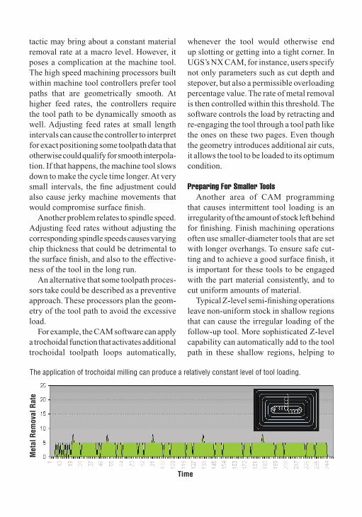
The application of trochoidal milling can produce a relatively constant level of tool loading.
Time
Met
al R
emov
al R
ate
Reprinted from the February 2005 MODERN MACHINE SHOP Magazine and Copyright © 2005 by Gardner Publications, Inc., 6915 Valley Ave., Cincinnati, Ohio 45244-3029.
ensure more uniform stock.Another feature, automatic
identification of flat horizontal faces in roughing operations, can prevent residual stock from being left on these types of faces. This also avoids exces-sive loading of the follow-up tool.
Tool EngagementThe engagement of the tool
with the stock has to be tightly controlled for effective hard milling. Chip thickness, which is determined by the spindle speed and feed rate, is part of the equation. But the horizontal and vertical engagement angles, which are often overlooked, also play an important role.
The horizontal engagement angle indi-cates the amount of sweep subtended by each cutting edge as it engages and leaves the stock.
The vertical engagement angle indicates the maximum instantaneous cutting edge engagement with the stock.
These factors together determine instanta-neous cutting forces and heat dissipation. For effective high speed hard milling, they need to be kept as consistent as possible.
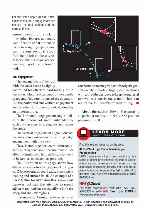
The illustration on this page shows how differences in the tool’s engagement in a typi-cal Z-level operation could cause inconsistent loading and surface finish. An example of a CAM feature for addressing this is an on-part stepover tool path that attempts to spread adjacent toolpath passes equally in both the steep and shallow regions.
To summarize: Constant material removal
Find this related resource on the Web:
Die/Mold High Speed Machining—ProgrammingMMS ONLINE covers high speed machining in a series of online presentations tailored to various industries and covering various aspects of the high speed machining process. For a link to the presentation on programming that is relevant to die/mold HSM, visit www.mmsonline.com/articles/020503.html
For more information from UGS, call (800) 498-5351 or enter MMS Direct code 951WB at www.mmsonline.com
LEARN MOREwww.mmsonline.com
can be made an integral part of toolpath gen-eration. By providing high speed machines with tool paths designed to keep the material removal rate consistent, a mold shop can realize the full benefits of hard milling.
About the author: Edwin Gasparraj is a specialist involved in NX CAM product planning for UGS.
For the same depth of cut, differ-ences in the tool’s engagement can change the tool loading and the surface finish.
Cut Depth 1mm
Cut Depth 1mm


