considered. With our proposed MIMO OFDM radar, there is no ...xxia/MIMOOFDMRadar.pdf · Fig. 1....
18
MIMO OFDM Radar IRCI Free Range Reconstruction With Sufficient Cyclic Prefix XIANG-GEN XIA, Fellow, IEEE University of Delaware Newark, DE, USA TIANXIAN ZHANG LINGJIANG KONG, Senior Member, IEEE University of Electronic Science and Technology of China Chengdu Sichuan, P. R. China In this paper, we propose multiple-input multiple-output (MIMO) orthogonal frequency division multiplexing (OFDM) radar with sufficient cyclic prefix (CP), where all OFDM pulses transmitted from different transmitters share the same frequency band and are orthogonal to each other for every subcarrier in the discrete frequency domain. The orthogonality is not affected by time delays from transmitters. Thus, our proposed MIMO OFDM radar has the same range resolution as single transmitter radar and achieves full spatial diversity. Orthogonal designs are used to achieve this orthogonality across the transmitters, with which it is only needed to design OFDM pulses for the first transmitter. We also propose a joint pulse compression and pulse coherent integration for range reconstruction. In order to achieve the optimal signal-to-noise ratio (SNR) for the range reconstruction, we apply the paraunitary filterbank theory to design the OFDM pulses. We then propose a modified iterative clipping and filtering (MICF) algorithm for the designs of OFDM pulses jointly, when other important factors, such as peak-to-average power ratio (PAPR) in time domain, are also Manuscript received June 26, 2014; revised November 10, 2014, January 1, 2015; released for publication January 18, 2015. DOI. No. 10.1109/TAES.2015.140477. Refereeing of this contribution was handled by F. Gini. X.-G. Xia’s research was partially supported by the Air Force Office of Scientific Research (AFOSR) under Grant FA9550-12-1-0055. T. Zhang’s research was supported by the Fundamental Research Funds for the Central Universities under Grant ZYGX2012YB008 and by the China Scholarship Council (CSC) and was done when he was visiting the University of Delaware, Newark, DE. L. Kong’s research was supported by the National Natural Science Foundation of China under Grants 61178068, the Fundamental Research Funds of Central Universities under Grants ZYGX2012Z001, the Program for New Century Excellent Talents in University under Grant A1098524023901001063. Authors’ addresses: X.-G. Xia, Department of Electrical and Computer Engineering, University of Delaware, Newark, DE 19716. T. Zhang, L. Kong, School of Electronic Engineering, University of Electronic Science and Technology of China, Chengdu, Sichuan, P.R. China, 611731. E-mail: ([email protected]). 0018-9251/15/$26.00 C 2015 IEEE considered. With our proposed MIMO OFDM radar, there is no interference for the range reconstruction not only across the transmitters but also across the range cells in a swath called inter-range-cell interference (IRCI) free that is similar to our previously proposed CP-based OFDM radar for single transmitter. Simulations are presented to illustrate our proposed theory and show that the CP-based MIMO OFDM radar outperforms the existing frequency-band shared MIMO radar with polyphase codes and also frequency division MIMO radar. I. INTRODUCTION The multiple-input multiple-output (MIMO) concept using multiple transmit and receive antennas has been intensively investigated in the last decades in wireless com- munications to collect spatial diversity, see, for example, [1, 2]. In recent years, this concept has been introduced to the radar applications [3–5], which is named “MIMO radar.” Unlike the traditional mono-static radar or phased-array radar, MIMO radar systems employ multiple transmitters, multiple receivers, and multiple orthogonal signals, and can provide more degrees of freedom for the design of a radar system as well as more advantages for radar signal processing. According to the configuration of anten- nas/transmitters, MIMO radar systems can be divided into two types, namely statistical MIMO radar and colocated MIMO radar. For statistical MIMO radar, the transmitters and receivers are widely separated, then, a target can be observed from different spatial aspects, resulting in spatial diversity and performance improvements of target detection [3], synthetic aperture radar (SAR) applications [6], and direction of arrival estimation [7, 8]. For colocated MIMO radar, the transmitters and receivers are located closely enough. By exploiting waveform diversity, colocated MIMO radar can improve the flexibility for transmit beam design [4, 5], and low-grazing angle target tracking [9]. The above advantages of MIMO radar systems are achieved under the assumption that the transmitted signals are orthogonal to each other in time domain despite their arbitrary time delays. It is well known that this assumption can hold only when the frequency bands of all the transmitted signals do not overlap each other [10]. Then, the signals of different transmitter and receiver pairs can be independently processed and the spatial diversity can be obtained. This MIMO radar system can be denoted as “frequency division MIMO radar” system, which requires a relatively wide frequency band, since each transmitter occupies a unique frequency band. Therefore, the frequency spectrum efficiency is low, especially, for a high range resolution radar system. In other words, the spatial diversity advantage of frequency division MIMO radar systems is built upon the sacrifice of the range resolution. To increase the spectrum efficiency or the range resolution of frequency division MIMO radar systems, there have been many works on investigating “frequency-band shared MIMO radar” systems through the design of time domain orthogonal codes/sequences and/or waveforms, which contain not only good autocorrelation but also good cross-correlation properties [11–18] However, the design 2276 IEEE TRANSACTIONS ON AEROSPACE AND ELECTRONIC SYSTEMS VOL. 51, NO. 3 JULY 2015
Transcript of considered. With our proposed MIMO OFDM radar, there is no ...xxia/MIMOOFDMRadar.pdf · Fig. 1....
MIMO OFDM Radar IRCI FreeRange Reconstruction WithSufficient Cyclic Prefix
XIANG-GEN XIA, Fellow, IEEEUniversity of DelawareNewark, DE, USA
TIANXIAN ZHANGLINGJIANG KONG, Senior Member, IEEEUniversity of Electronic Science and Technology of ChinaChengdu Sichuan, P. R. China
In this paper, we propose multiple-input multiple-output(MIMO) orthogonal frequency division multiplexing (OFDM) radarwith sufficient cyclic prefix (CP), where all OFDM pulsestransmitted from different transmitters share the same frequencyband and are orthogonal to each other for every subcarrier in thediscrete frequency domain. The orthogonality is not affected by timedelays from transmitters. Thus, our proposed MIMO OFDM radarhas the same range resolution as single transmitter radar andachieves full spatial diversity. Orthogonal designs are used to achievethis orthogonality across the transmitters, with which it is onlyneeded to design OFDM pulses for the first transmitter. We alsopropose a joint pulse compression and pulse coherent integration forrange reconstruction. In order to achieve the optimal signal-to-noiseratio (SNR) for the range reconstruction, we apply the paraunitaryfilterbank theory to design the OFDM pulses. We then propose amodified iterative clipping and filtering (MICF) algorithm for thedesigns of OFDM pulses jointly, when other important factors, suchas peak-to-average power ratio (PAPR) in time domain, are also
Manuscript received June 26, 2014; revised November 10, 2014, January1, 2015; released for publication January 18, 2015.
DOI. No. 10.1109/TAES.2015.140477.
Refereeing of this contribution was handled by F. Gini.
X.-G. Xia’s research was partially supported by the Air Force Office ofScientific Research (AFOSR) under Grant FA9550-12-1-0055. T.Zhang’s research was supported by the Fundamental Research Funds forthe Central Universities under Grant ZYGX2012YB008 and by theChina Scholarship Council (CSC) and was done when he was visiting theUniversity of Delaware, Newark, DE. L. Kong’s research was supportedby the National Natural Science Foundation of China under Grants61178068, the Fundamental Research Funds of Central Universitiesunder Grants ZYGX2012Z001, the Program for New Century ExcellentTalents in University under Grant A1098524023901001063.
Authors’ addresses: X.-G. Xia, Department of Electrical and ComputerEngineering, University of Delaware, Newark, DE 19716. T. Zhang, L.Kong, School of Electronic Engineering, University of ElectronicScience and Technology of China, Chengdu, Sichuan, P.R. China,611731. E-mail: ([email protected]).
0018-9251/15/$26.00 C© 2015 IEEE
considered. With our proposed MIMO OFDM radar, there is nointerference for the range reconstruction not only across thetransmitters but also across the range cells in a swath calledinter-range-cell interference (IRCI) free that is similar to ourpreviously proposed CP-based OFDM radar for single transmitter.Simulations are presented to illustrate our proposed theory andshow that the CP-based MIMO OFDM radar outperforms theexisting frequency-band shared MIMO radar with polyphase codesand also frequency division MIMO radar.
I. INTRODUCTION
The multiple-input multiple-output (MIMO) conceptusing multiple transmit and receive antennas has beenintensively investigated in the last decades in wireless com-munications to collect spatial diversity, see, for example, [1,2]. In recent years, this concept has been introduced to theradar applications [3–5], which is named “MIMO radar.”Unlike the traditional mono-static radar or phased-arrayradar, MIMO radar systems employ multiple transmitters,multiple receivers, and multiple orthogonal signals,and can provide more degrees of freedom for the design ofa radar system as well as more advantages for radar signalprocessing. According to the configuration of anten-nas/transmitters, MIMO radar systems can be divided intotwo types, namely statistical MIMO radar and colocatedMIMO radar. For statistical MIMO radar, the transmittersand receivers are widely separated, then, a target can beobserved from different spatial aspects, resulting in spatialdiversity and performance improvements of target detection[3], synthetic aperture radar (SAR) applications [6], anddirection of arrival estimation [7, 8]. For colocated MIMOradar, the transmitters and receivers are located closelyenough. By exploiting waveform diversity, colocatedMIMO radar can improve the flexibility for transmit beamdesign [4, 5], and low-grazing angle target tracking [9].
The above advantages of MIMO radar systems areachieved under the assumption that the transmitted signalsare orthogonal to each other in time domain despite theirarbitrary time delays. It is well known that this assumptioncan hold only when the frequency bands of all thetransmitted signals do not overlap each other [10]. Then,the signals of different transmitter and receiver pairs canbe independently processed and the spatial diversity canbe obtained. This MIMO radar system can be denoted as“frequency division MIMO radar” system, which requiresa relatively wide frequency band, since each transmitteroccupies a unique frequency band. Therefore, thefrequency spectrum efficiency is low, especially, for a highrange resolution radar system. In other words, the spatialdiversity advantage of frequency division MIMO radarsystems is built upon the sacrifice of the range resolution.To increase the spectrum efficiency or the range resolutionof frequency division MIMO radar systems, therehave been many works on investigating “frequency-bandshared MIMO radar” systems through the design of timedomain orthogonal codes/sequences and/or waveforms,which contain not only good autocorrelation but also goodcross-correlation properties [11–18] However, the design
2276 IEEE TRANSACTIONS ON AEROSPACE AND ELECTRONIC SYSTEMS VOL. 51, NO. 3 JULY 2015

of binary sequences [11, 12], polyphase sequences [13, 14],unimodular sequence sets [15], or chaotic phase codes [18]can only somewhat mitigate waveform cross-correlationeffects or reduce the sidelobes of autocorrelationfunction. The cross correlations between the delayed timedomain waveforms from different transmitters cannot bezero and thus cause interference among transmitters. Thislimits the collection of the spatial diversity. Therefore,the performance of MIMO radar systems will stillbe degraded by using the existing designed waveforms.
To deal with the sidelobe issues from the nonidealautocorrelations across the range cells in the conventionalSAR systems, in [19, 20] we have proposed a sufficientcyclic prefix (CP) based orthogonal frequency divisionmultiplexing (OFDM) SAR imaging for single transmitterradar systems. By using a sufficient CP, zero rangesidelobes and inter-range-cell interference (IRCI) freerange reconstruction can be achieved, which provides anopportunity for high resolution range reconstruction. Ashas been explained in [19], the major differences betweenour proposed CP-based OFDM SAR and the existingOFDM SAR systems are in two aspects. One is that asufficiently long CP is used at the transmitter and the CPshould be as long as possible when the number of rangecells in a swath is large. The other is the SAR imagingalgorithm at the receiver, which is not the matched filterreceiver by simply treating the CP-based OFDM signals asradar waveforms as is done in the existing OFDM radarsystems. With these two differences, the key feature of anOFDM system in communications applications ofconverting an intersymbol interference (ISI) channel tomultiple ISI-free subchannels is analogously obtained inour proposed CP-based OFDM SAR imaging as IRCI freerange reconstruction among range cells in aswath.
In this paper, we consider a frequency-band sharedstatistical MIMO radar range reconstruction using OFDMsignals with sufficient CP by generalizing the CP-basedOFDM SAR imaging from single transmitter and receiverto multiple transmitter and receiver radar systems called“MIMO OFDM radar.” With our newly proposedCP-based MIMO OFDM radar, all the signal waveformsfrom all the transmitters have the same frequency bandand thus the range resolution is not sacrificed and the sameas the single transmitter radar. Furthermore, theirarbitrarily time delayed versions are still orthogonal forevery subcarrier in the discrete frequency domain andtherefore, the spatial diversity from all the transmitters canbe collected the same as the frequency division MIMOradar. In addition to the two differences mentioned abovefor single transmitter and receiver CP-based OFDM radarsystems with the existing OFDM radar systems, theorthogonality in the time domain under arbitrary timedelays between different transmitters has not beenconsidered in most of the existing MIMO OFDM radarsystems [6, 8, 9] where IRCI exists not only among rangecells in a swath but also among the transmitters. Althoughit is considered in [7], IRCI is not the focus. In this paper,
IRCI free is achieved among both range cells in a swathand all the transmitters.
We first formulate the problem and describe the MIMOOFDM radar signal model by considering the feature ofsufficient CP-based OFDM pulses, where the CP part takesall zero values. Using the properties of frequency domainorthogonal OFDM pulses for every subcarrier betweendifferent transmitters, we then derive a MIMO OFDMradar range reconstruction algorithm, which includes thejoint processing of pulse compression and pulse coherentintegration. We also analyze the change of noise powerin every step of the range reconstruction and evaluate thepossible signal-to-noise ratio (SNR) degradation causedby the range reconstruction. We then propose the designcriterion for the multiple OFDM pulses used at transmitters.
The orthogonality for every subcarrier in the discretefrequency domain among the OFDM waveforms for all thetransmitters is done by employing the theory of orthogonaldesigns [21–28] that has been used as orthogonalspace-time codes in MIMO wireless communications[1, 2, 21–28]. To achieve the optimal SNRafter the range reconstruction, we propose a joint multipleOFDM pulse design method with a closed-form solutionby using paraunitary filterbank theory [29, 30]. With theparaunitary filterbank theory in the design of the MIMOOFDM waveforms, although the SNR after the rangereconstruction is maximized, it is not easy to search for thesequences to generate the MIMO OFDM waveforms so thattheir peak-to-average power ratio (PAPR) is low, while alow PAPR is important in radar practical implementations.
By considering the trade-off between the PAPR andthe SNR degradation within the range reconstruction, wepropose a modified iterative clipping and filtering (MICF)joint OFDM pulse design method, which can obtain OFDMpulses with low PAPRs and an acceptable SNR degradation.We then present some simulations to demonstratethe performance of the proposed MICF joint OFDM pulsedesign method. By comparing with the frequency-bandshared MIMO radar using polyphase code waveforms andfrequency division MIMO radar using linear frequencymodulated (LFM) waveforms, we present some simulationsto illustrate the performance advantage of the proposedMIMO OFDM radar range reconstruction method. We findthat, with the designed OFDM pulses from our proposedMICF method, our proposed CP-based MIMO OFDMradar can obtain the range reconstruction without anyinterference between different transmitters and achievethe full spatial diversity from all the transmitters andreceivers. Meanwhile, it can still maintain the advantageof IRCI free range reconstruction with insignificant SNRdegradation and completely avoid the energy redundancyin the case when there are only a limited number of rangecells of interest. Note that constant orthogonal/unitarymatrices for every subcarrier in the discretefrequency domain across transmitters and waveformshave been constructed in [7] where only a few parametersare used and may limit the waveform designs withother desired properties, such as those discussed above.
XIA ET AL.: MIMO OFDM RADAR IRCI FREE RANGE RECONSTRUCTION WITH CP 2277
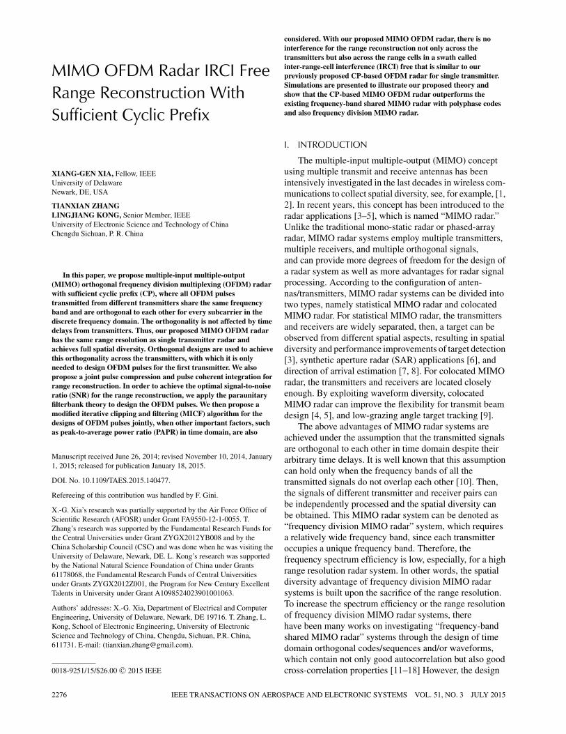
Fig. 1. MIMO OFDM radar geometry.
The remainder of this paper is organized as follows. InSection II, we establish the CP-based MIMO OFDM radarsignal model and describe the problem of interest. InSection III, we propose CP-based MIMO OFDM radarrange reconstruction. In Section IV, we propose two newarbitrary length OFDM sequence design methods. InSection V, we show some simulation results. Finally, inSection VI, we conclude this paper.
II. CP-BASED MIMO OFDM RADAR SIGNAL MODELAND PROBLEM FORMULATION
Consider a MIMO radar system with T transmittersand R receivers, as shown in Fig. 1. All the antennas of theMIMO radar system we consider in this paper are locatedin a fixed area, and the antennas are not as close to eachother as colocated MIMO radars [4, 5]. The instantaneouscoordinate of the αth transmitter and the βth receiver are,respectively, (xα, yα, zα), α = 1, . . . , T, and (xβ, yβ, zβ),β = 1, . . . , R, where zα and zβ are the altitudes of thecorresponding antennas. After the demodulation tobaseband, the complex envelope of the received signalobserved at the βth receiver due to a transmission from theαth transmitter and reflection from the far field scatterersin the mth range cell with instantaneous coordinate (xm,ym, zm) (and excluding noise) is given by
uβ,α,m (t) = gβ,α,mexp{−j2πfc[τα,m + τβ,m]}× sα
(t − τα,m − τβ,m
), (1)
where sα (t) is a transmitted signal of the αth transmitter,fc is the carrier frequency, gβ ,α ,m is the radar cross section(RCS) coefficient caused from the scatterers in the mthrange cell within the radar mainbeam footprint and relatedto the αth transmitter and the βth receiver. We assume thatthe mainbeam footprints of each receiver are overlappedtogether and included in the footprints of the transmitters.τα,m = Rα,m
cis the signal propagation time delay between
the αth transmitter and the mth range cell, and similarly,τβ,m = Rβ,m
cis the signal propagation time delay between
the mth range cell and the βth receiver, where c is thespeed of light,Rα,m =
√(xm − xα)2 + (ym − yα)2 + (zm − zα)2 and
Rβ,m =√
(xm − xβ)2 + (ym − yβ)2 + (zm − zβ)2 are,respectively, the slant range between the αth transmitterand the mth range cell and the slant range between the mthrange cell and the βth receiver.
At the receiver, to a transmitted signal with bandwidthB, the received signal is sampled by the analog-to-digital(A/D) converter with sampling interval length Ts = 1
Band
the range resolution is ρ = c2B
= c2Ts . Assume that the
width for the radar footprints in the range direction is Rw.Then, a range profile can be divided into M = Rw
ρrange
cells as in Fig. 1 that is determined by the radar system.From the far field assumption, as we have discussed in[19], we can obtain
Rα,m = Rα,0 + mρ, m = 0, 1, . . . , M − 1, (2a)
Rβ,m = Rβ,0 + mρ, m = 0, 1, . . . , M − 1. (2b)
Then, the signal propagation time delay between theαth transmitter and the βth receiver can be denoted by
τα,m + τβ,m = τβ,α,0 + mTs, (3)
where
τβ,α,0 = Rα,0 + Rβ,0
c. (4)
In radar applications, there is usually more than onescatterer within a range cell, and each scatterer owns itsunique delay and phase. However, for a given rangeresolution (or signal bandwidth), a radar is not able todistinguish these individual scatterers, and the responsesof all these scatterers are summarized as the response ofone range cell with a single delay and phase in thereceiver. Thus, each range cell can be treated as onepoint-like target. This kind of model is reasonable andcommonly used in the existing radar applications [31].
Let τmin be the minimal signal propagation time delaybetween all the transmitter and receiver pairs through thenearest (m = 0) range cell. And τmin is defined as
τmin = minβ=1,...,Rα=1,...,T
{τβ,α,0
}. (5)
By arranging the antennas, the time delays betweendifferent transmitter and receiver pairs can approximatelysatisfy the relationship
ηβ,α = τβ,α,0 − τmin
Ts
, (6)
where ηβ,α ∈ N. The maximal relative time delaydifference among all the transmitter and receiver pairs isηmaxTs, and
ηmax = maxβ,α
{ηβ,α
}. (7)
We remark that the values of ηβ ,α may slightly change,when a radar scans the radar surveillance area withdifferent azimuth angle. But, in practice, considering thefar field assumption, ηβ ,α is constant within a consecutive
2278 IEEE TRANSACTIONS ON AEROSPACE AND ELECTRONIC SYSTEMS VOL. 51, NO. 3 JULY 2015
radar scan sector. Thus, the radar surveillance area can bedivided into different radar scan sectors with differentprecalculated values of ηβ ,α . Also, parameter ηmax isdetermined by the system configuration and may beestimated a priori, and it is used for the MIMO OFDMpulse designs later.
In most of the MIMO radar literature, it is assumedthat the transmitted signals are orthogonal to each otherand even when there are different time delays among thesesignals, i.e.,
∫sα(t)sα(t − τ )∗dt = 0 for α �= α, and
arbitrary time delay c of interest, where (·)* denotes thecomplex conjugate, or it is assumed that there are nodifferent time delays among the transmitted signals frommultiple transmitters. However, in practice, this isgenerally not possible [10], unless the frequency bands ofall the transmitted signals do not overlap with each other,which then leads to frequency division MIMO radar andwill either reduce the range resolution or not be able tocollect the transmitter spatial diversity as we havementioned in the Introduction. As we see later in thispaper, these two assumptions will not be needed with ourproposed MIMO OFDM radar.
In this paper, we consider that there are P coherentpulses in a radar coherent processing interval (CPI) (as wesee later that some of these P pulses may be allzero-valued). Each non-zero-valued pulse is an OFDMsignal with N subcarriers and a bandwidth of B Hz. LetS(p)
α = [S(p)α,0, S
(p)α,1, . . . , S
(p)α,N−1]T represent the complex
weights transmitted over the subcarriers of the pth OFDMpulse and the αth transmitter, where p = 0, 1, . . . , P – 1,and (·)T denotes the transpose. For convenience, wenormalize the total transmitted energy within a CPI to 1,and assume the energy of each transmitted pulse is the
same, i.e.,N−1∑k=0
|S(p)α,k|
2 = 1TP1
for all non-zero-valued pulses
where P1 is the number of non-zero-valued pulses. All thetransmitted signals share the same frequency band. Then,a discrete time OFDM signal is the inverse fast Fouriertransform (IFFT) of the vector S(p)
α and the correspondingtime domain OFDM signal is
s(p)α (t) = 1√
N
N−1∑k=0
S(p)α,kexp {j2πk�f t} ,
t ∈ [pTr, pTr + T + TGI ] , (8)
where �f = BN
= 1T
is the subcarrier spacing, and Tr isthe time interval between two consecutive pulses within aCPI. [pTr, pTr + TGI) is the time duration of the guardinterval that corresponds to the CP in the discrete timedomain as we see later in more detail and its length TGI isspecified later as well; T is the length of the OFDM signalexcluding CP. Due to the periodicity of the exponentialfunction exp(·) in (8), the tail part of s
(p)α (t) for t in (pTr,
pTr + T + TGI] is the same as the head part of s(p)a (t) for
t in [pTr, pTr + TGI). Note that in the above transmission,the CP is added to each pulse s
(p)α (t).
Then, the complex envelope of the received signal inthe βth receiver due to the pth transmitted pulses of all thetransmitters and the reflection from all range cells withinthe mainbeam footprint can be written as
u(p)β (t)
= 1√N
T∑α=1
M−1∑m=1
gβ,α,mexp{−j2πfc
[τα,m + τβ,m
]}×
N−1∑k=0
S(p)α,kexp
{j2πk
T
[t − τα,m − τβ,m
]}+w(p)β (t),
(9)
where w(p)β (t) represents the noise. For convenience, in
this paper, we assume the RCS coefficients gβ ,α ,m areconstant within a CPI, and it can be generalized to the caseof maneuvering targets similar to what is done in theliterature.
In our MIMO radar applications, the values of timedelays τβ ,α ,0 are different from one transmitter andreceiver pair to another, which depend on the relativelocations of antennas. All the received signals due to T
transmitters and reflections from each range cell willoverlap together at the receiver and cannot be separated ingeneral. Thus, the interferences will occur includingdifferent range cells and different transmitted signals fromthe transmitters and result in IRCI. Notice that, to onerange cell, each transmitter and receiver pair can beregarded as one path of communications, and, to onetransmitter and receiver pair each range cell can also beregarded as one path of communications as analyzed in[19]. Comparing with the main path that we define as theshortest path, the longest time delay among all the paths is(ηmax + M – 1)Ts. As we have mentioned in [19], toeliminate the interference between different transmittedsignals and IRCI, similar to OFDM systems incommunications, the time duration of guard intervalshould be at least (ηmax + M – 1)Ts. For convenience, weuse CP length ηmax + M – 1 in this paper, i.e., a CP oflength ηmax + M – 1 is added at the beginning of anOFDM pulse, and then the guard interval length TGI in theanalog transmission signal is TGI = (ηmax + M – 1)Ts.Notice that T = NTs, so the time duration of an OFDMpulse is To = T + TGI = (N + ηmax + M – 1)Ts. Tocompletely avoid the range interference between differenttransmitted signals and range cells, the number N of theOFDM signal subcarriers should satisfy N ≥ ηmax + M aswe have analyzed in [19] and will be seen in more detaillater, and it is also well understood in communicationsapplications [32].
III. CP-BASED MIMO OFDM RADAR RANGERECONSTRUCTION
This section is on the MIMO radar rangereconstruction that includes the joint processing of pulsecompression and pulse coherent integration. Going backto (9), for the pth pulse, let the sampling at all receivers be
XIA ET AL.: MIMO OFDM RADAR IRCI FREE RANGE RECONSTRUCTION WITH CP 2279
aligned with the start of the received signals after pTr +τmin seconds of the transmitted pulses, where we recallthat Tr is the time interval between two consecutivepulses. Combining with (3), (6), and (9), u
(p)β (t) can be
converted to the discrete time linear convolution of thetransmitted sequence with the weighting RCS coefficientsdβ ,α ,m after the sampling t = pTr + τmin + iTs and thereceived sequence can be written as
u(p)β,i =
T∑α=1
M−1∑m=0
dβ,α,ms(p)α,i−m−ηβ,α
+ w(p)β,i ,
i = 0, 1, . . . , N + 2 (ηmax + M) − 3, (10)
where
dβ,α,m = gβ,α,mexp{−j2πfc[τα,m + τβ,m]}, (11)
in which 2π fc [τα ,m + τβ ,m] in the exponential is knownand related to the target location,1 and s
(p)α,i is the complex
envelope of the OFDM pulse in (8) with time duration t∈[pTr, pTr + T + TGI] for T = NTs and TGI = (ηmax + M– 1)Ts. In (10), w
(p)β,i is the noise. After sampling at t = pTr
+ iTs, (8) can be recast as
s(p)α,i = s(p)
α (iTs) = 1√N
N−1∑k=0
S(p)α,kexp
{j2πki
N
},
i = 0, 1, . . . , N + ηmax + M − 2, (12)
and s(p)α,i = 0 if i < 0 or i > N + ηmax + M – 2.
When the sequenceuβ = [uβ,0, uβ,1, . . . , uβ,N+2(ηmax+M)−3]T in (10) isreceived, the first and the last ηmax + M – 1 samples areremoved as [19], and then, we obtain
u(p)β,n =
T∑α=1
M−1∑m=0
dβ,α,ms(p)α,n+ηmax+M−m−ηβ,α−1 + w
(p)β,n,
n = 0, 1, . . . , N − 1. (13)
The OFDM demodulator then performs the N-pointfast Fourier transform (FFT) on the vectoru(p)
β = [u(p)β,0, . . . , u
(p)β,N−1]T , and obtains
U (p)β = [U (p)
β,0, . . . , U(p)β,N−1]T , where U
(p)β,k can be denoted
as
U(p)β,k = Dβ,k S
(p)k + W
(p)β,k , k = 0, 1, . . . , N − 1, (14)
where S(p)k = [S(p)
1,k , . . . , S(p)T,k]T is a T × 1 column vector.
W(p)β,k is the FFT of noise, and Dβ,k = [Dβ,1,k, . . . , Dβ,T,k]
with
Dβ,α,k =M−1∑m=0
dβ,α,mexp
{j2πk
(ηmax + M − ηβ,α − 1
)N
}
×exp
{−j2πkm
N
}, k = 0, 1, . . . , N − 1, (15)
1 Notice that the values of j2π fcτα ,m and j2π fcτβ ,m form the transmittersteering vector and receiver steering vector [33], respectively, which areoften assumed known.
where, dβ ,α ,m is the weighting RCS coefficient from theαth transmitter, the mth range cell, and the βth receiver.
From the constant assumption of gβ ,α ,m within a CPI,for given β, α, and m, the values of dβ ,α ,m in (11) andDβ ,α ,k in (15) are also constant within a CPI. Combiningall the received signals of R receivers and P pulses withina CPI, we can obtain the following matrix representation:
Uk = DkSk + Wk, k = 0, 1, . . . , N − 1, (16)
where Uk = [U (0)k , U (1)
k , . . . , U (P−1)k ] is an R × P matrix,
U (p)k = [U (p)
1,k , U(p)2,k , . . . , U
(p)R,k]T is an R × 1 column vector
for 0 ≤ p ≤ P – 1.
Sk�=[
S(0)k , S
(1)k , . . . , S
(P−1)k
]=
⎡⎢⎢⎢⎢⎢⎣S
(0)1,k S
(1)1,k · · · S
(P−1)1,k
S(0)2,k S
(1)2,k · · · S
(P−1)2,k
......
. . ....
S(0)T,k S
(1)T,k · · · S
(P−1)T,k
⎤⎥⎥⎥⎥⎥⎦(17)
is a T × P matrix. Wk = [W (0)k , W (1)
k , . . . , W (P−1)k ] is an
R × P matrix, W (p)k = [W (p)
1,k , W(p)2,k , . . . , .W
(p)R,k]T is an
R × 1 column vector. And
Dk =
⎡⎢⎢⎢⎢⎢⎣D1,1,k D1,2,k · · · D1,T,k
D2,1,k D2,2,k · · · D2,T,k
......
. . ....
DR,1,k DR,2,k · · · DR,T,k
⎤⎥⎥⎥⎥⎥⎦ (18)
is an R × T matrix.By assuming P ≥ T, we can construct such a T × P
matrix Sk to guarantee SkS+k = IT for all k, where IT is the
T × T identity matrix, S+k = S†
k(SkS†k)−1 ∈ C
P×T is thePenrose-Moore pseudoinverse of Sk, and (·)† denotes theconjugate transpose. Note that as long as matrix Sk has fullrow rank, i.e., 1 × P weight vectors in the P OFDMwaveforms from all transmitters are linearly independenton every subcarrier k, property SkS+
k = IT is satisfied.Then, the estimate of Dk in (16) is
Dk = UkS+k = Dk + Wk, (19)
where Wk = WkS+k denotes the new noise matrix. One
can see from the above estimate that the new noise matrixis obtained by multiplying the inverse of matrix Sk to theoriginal noise matrix Wk for each subcarrier index k.Clearly, in order not to enhance the noise, it is desired thatthe matrix Sk is unitary, which is similar to the MIMOOFDM channel estimation in wireless communications [1,2, 32]. Since Sk is a flat matrix in general, in what followswe require that the row vectors of Sk are orthogonal toeach other and have the same norm called flat unitarymatrix, i.e., SkS†
k = IT. This means that the weight vectorsat every subcarrier k in the OFDM waveforms transmittedthrough T transmitters are orthogonal to each other amongdifferent transmitters, i.e., the discrete versions infrequency domain are orthogonal to each other for everysubcarrier, which still holds when there are time delays
2280 IEEE TRANSACTIONS ON AEROSPACE AND ELECTRONIC SYSTEMS VOL. 51, NO. 3 JULY 2015
among the corresponding waveforms in time domain,although the delayed waveforms may not be orthogonal intime domain. This property is fundamentally differentfrom most of the existing MIMO radars including theexisting MIMO OFDM radars.
According to (15), vector Dβ ,α = [Dβ ,α ,0, Dβ ,α ,1, . . .,Dβ ,α ,N – 1]T is just the N-point FFT of vector
√Nγ , where
γ is an N-dimensional vector, which is a right cyclic shiftof ηmax + M – ηβ ,α – 1 positions of vector⎡⎣dβ,α,0, dβ,α,1, · · · , dβ,α,M−1, 0, · · · , 0︸ ︷︷ ︸
N−M
⎤⎦T
,
where dβ ,α ,m are the weighting RCS coefficients, similarto the single transmitter and single receiver case studied in[19].
Then, the pulse compression and coherent integrationcan be achieved by performing the N-point IFFT operationon vector Dβ,α = [Dβ,α,0, Dβ,α,1, . . . , Dβ,α,N−1]T and weobtain
dβ,α,m = 1√N
N−1∑n=0
Dβ,α,nexp
{j2πmn
N
},
m = 0, 1, . . . , N − 1. (20)
So, the estimate of dβ ,α ,m can be achieved by a leftcyclic shift of ηmax + M – ηβ ,α – 1 positions of vectordβ,α,m, i.e., vector [dβ,α,0, . . . , dβ,α,M−1]T is equal to thefirst M elements of vector
[dβ,α,N−ηmax−M+ηβ,α+1, . . . , dβ,α,N−1,
dβ,α,0, . . . , dβ,α,N−ηmax−M+ηβ,α]T .
We then obtain the following estimates of the Mweighting RCS coefficients at the βth receiver due to theαth transmitter:
dβ,α,m =√
Ndβ,α,m + wβ,α,m, m = 0, 1, . . . , M − 1,
(21)where wβ ,α ,m is the mth output of the N-point IFFT of thevector [Wβ,α,0, Wβ,α,1, . . . , Wβ,α,N−1]T that is the βth rowand the αth column element of matrix Wk for k = 0, 1, . . .
, N – 1. Wβ,α,k can be written as
Wβ,α,k =
P−1∑p=0
W(p)β,kS
(p)α,k
P−1∑p=0
∣∣∣S(p)α,k
∣∣∣2 , k = 0, 1, . . . , N − 1. (22)
In (21), dβ ,α ,m can be recovered without anyinterference from other transmitted signals or IRCI fromother range cells. Then, using (11), we can compensate thephase and obtain the estimate of the RCS coefficientgβ ,α ,m as
gβ,α,m = dβ,α,mexp{j2πfc
[τα,m + τβ,m
]}. (23)
In the above joint pulse compression and coherentintegration, the operations of FFT in (14), the estimate ofDk in (19), and IFFT in (20) are applied. Thus, we need to
analyze the changes of the noise power in each step of theabove range reconstruction method. Assume that the noisecomponent w
(p)β,n in (13) is a complex white Gaussian
variable with zero-mean and the same variance σ 2, i.e.,w
(p)β,n ∼ CN (0, σ 2) for all receivers β, pulses p, and
samples n. Since the FFT operation is unitary, after theprocess in (14), the additive noise power of W
(p)β,k does not
change, i.e., W(p)β,k ∼ CN (0, σ 2). In the same way, the
noise power of each element in Wk in (16) is also σ 2.However, after the operation for the estimate of Dk in (19),the variance of a noise component Wβ,α,k in (22) can becalculated as
E{Wβ,α,kW
†β,α,k
}= σ 2
⎡⎣P−1∑p=0
∣∣∣S(p)α,k
∣∣∣2⎤⎦−1
,
and thus
Wβ,α,k ∼ CN
⎛⎜⎝0, σ 2
⎡⎣P−1∑p=0
∣∣∣S(p)α,k
∣∣∣2⎤⎦−1
⎞⎟⎠ ,
k = 0, 1, . . . , N − 1,
for all β and α. Moreover, after the IFFT operation in (20),we then have finished the joint pulse compression andcoherent integration. The noise power of wβ ,α ,m in (21) is
E{wβ,α,mw
†β,α,m
}= σ 2
N
N−1∑k=0
⎡⎣P−1∑p=0
∣∣∣S(p)α,k
∣∣∣2⎤⎦−1
and
wβ,α,m ∼ CN
⎛⎜⎝0,σ 2
N
N−1∑k=0
⎡⎣P−1∑p=0
∣∣∣S(p)α,k
∣∣∣2⎤⎦−1
⎞⎟⎠ .
Thus, from (21), we can obtain the SNR of the signalafter the joint pulse compression and coherent integrationat the βth receiver due to the transmission from the αthtransmitter and reflected from the mth range cell as,
SNRβ,α,m = N2∣∣dβ,α,m
∣∣2σ 2
N−1∑k=0
[P−1∑p=0
∣∣∣S(p)α,k
∣∣∣2]−1 . (24)
Notice that a larger SNRβ ,α ,m can be obtained with asmaller value of
N−1∑k=0
⎡⎣P−1∑p=0
∣∣∣S(p)α,k
∣∣∣2⎤⎦−1
by designing S(p)α,k . With a given αth transmitter and the
energy constraint
P−1∑p=0
N−1∑k=0
∣∣∣S(p)α,k
∣∣∣2 = 1
T,
XIA ET AL.: MIMO OFDM RADAR IRCI FREE RANGE RECONSTRUCTION WITH CP 2281
whenP−1∑p=0
|S(p)α,k|
2has constant module for all k, i.e.,
P−1∑p=0
∣∣∣S(p)α,0
∣∣∣2 =P−1∑p=0
∣∣∣S(p)α,1
∣∣∣2 = . . . =P−1∑p=0
∣∣∣S(p)α,N−1
∣∣∣2 = 1
NT,
(25)we obtain the minimal value of
N−1∑k=0
⎡⎣P−1∑p=0
∣∣∣S(p)α,k
∣∣∣2⎤⎦−1
= N2T.
In this case, the maximal SNR after the joint pulsecompression and coherent integration can be obtained as
SNR(max)β,α,m = max
Sα :‖Sα‖2= 1T
{SNRβ,α,m
}=∣∣dβ,α,m
∣∣2Tσ 2
, (26)
where Sα =[(
S(0)α
)T, . . . ,
(S(P−1)
α
)T ]T
∈ CPN×1.
Thus, for the αth transmitter, the optimal signal S(p)α,k
should satisfy a requirement that the transmitted energy
summations of the P pulses within a CPI, i.e.,P−1∑p=0
|S(p)α,k|
2,
have constant module for all k. Otherwise, the SNR afterthe range reconstruction will be degraded. Here, we definethe SNR degradation factor as
ξ = SNRβ,α,m
SNR(max)β,α,m
= N2T
N−1∑k=0
[P−1∑p=0
∣∣∣S(p)α,k
∣∣∣2]−1 . (27)
Notice that ξ ∈ (0,1] is independent of the noise power σ 2
and the weighting RCS coefficient dβ ,α ,m. Since weassume that the row vectors of matrix Sk are orthogonal toeach other and have the same norm, the above degradationfactor ξ is also independent of β and α. The SNRdegradation factor ξ in (27) is for the performance of bothpulse compression and coherent integration of all the Ppulses within a CPI, but not only the pulse compression ofa single pulse in [20].
We recall that the number of the OFDM signalsubcarriers should satisfy N ≥ ηmax + M. Thus, the lengthof the transmitted signals should be increased with theincreases of the width Rw for the radar footprints in therange direction and/or ηmax. The pulse length will be muchlonger than the traditional radar pulse for a wide width Rw
(or large M) and/or a large delay ηmax, which may be aproblem, especially for covert/military radar applications.Meanwhile, the CP removal for the elimination of theinterference at the receivers may cause high transmittedenergy redundancy as we have mentioned in [20].Therefore, it is necessary for us to achieve MIMO OFDMradar with arbitrary pulse length that is independent of Rw.The main idea is to generate P pulsess
(p)α (t), t ∈ [pTr, pTr + T + TGI ], p = 0,1, . . . , P – 1, for
all T transmitters, such that the discrete time sequence ofs
(p)α (t), pTr ≤ t ≤ pTr + T + TGI :
s(p)α,i = s
(p)α (iTs), 0 ≤ i ≤ N + ηmax + M − 2 in (12), is
zero at the head and the tail parts as[s
(p)α,0, . . . , s
(p)α,ηmax+M−2
]T
=[s
(p)α,N , . . . , s
(p)α,N+ηmax+M−2
]T
= 0(ηmax+M−1)×1. (28)
In the meantime, s(p)α,i is also a sampled discrete time
sequence of an OFDM pulse in (8) for t ∈ [pTr, pTr + T+ TGI]. This zero head and tail condition (28) is the sameas that in [20]. Then, in this case, the continuous timesignal s
(p)α (t) is only transmitted on the time interval t ∈
[pTr + TGI, pTr + T] that has length T – TGI, where TGI
is the length of the guard interval and also the zero-valuedhead part of the signal that leads to the zero-valued CPpart at the tail. Since T can be arbitrarily designed, theOFDM pulse length T – TGI can be arbitrary as well. Formore details, we refer to [20]. Based on the aboveanalysis, the key task of the following section is the designof these multiple OFDM sequences.
IV. DESIGN OF MULTIPLE OFDM SEQUENCES
In this section, we design the weight sequences in theP OFDM pulses for each transmitter, i.e., the matrixSk = [S(p)
α,k]1≤α≤T,0≤p≤P−1 for k = 0,1,..., N – 1 in (17).There are three indices here: one is the transmitter indexα, one is the OFDM pulse index p for each transmitter,and the third one is the subcarrier index k. We start withthe design criterion.
A. Design Criterion
Any segment of an OFDM pulse in (8) is determinedby a weight sequence S(p)
α = [S(p)α,0, S
(p)α,1, . . . , .S
(p)α,N−1]T
that is determined by its N-point IFFTs(p)α = [s(p)
α,0, s(p)α,1, . . . , s
(p)α,N−1]T . Thus, the design of s(p)
α is
equivalent to the design of S(p)α . Based on the above
discussions, s(p)α and S(p)
α should satisfy the followingconditions.
1) Frequency domain orthogonality amongtransmitters for every subcarrier: As was mentionedearlier, in order not to enhance the noise in the estimate in(19) for RCS coefficients, matrix Sk has to be a flat unitarymatrix, i.e., SkS†
k = IT for each k = 0,1, . . . , N – 1.Specifically, the sequence Sα ,k should be orthogonal tosequence Sα,k for different transmitters α �= α and1 ≤ α, α ≤ T, and have the same norm, whereSα,k = [S(0)
α,k, S(1)α,k, . . . , S
(P−1)α,k ] is the αth row of Sk. Note
that this orthogonality is for every subcarrier in the discretefrequency domain of the signal waveforms but not in thetime domain as commonly used in a MIMO radar. Theadvantage of this orthogonality in the frequency domain isthat it is not affected by time delays in the time domain,while the orthogonality in the time domain is sensitive toany time delays. In addition, this discrete orthogonality inthe frequency domain does not require that the frequencybands of the waveforms do not overlap each other ascommonly used in the frequency division MIMO radar
2282 IEEE TRANSACTIONS ON AEROSPACE AND ELECTRONIC SYSTEMS VOL. 51, NO. 3 JULY 2015
and in fact, all the frequency bands of the T waveformscan be the same. It implies that the range resolution is notsacrificed as is done in frequency division MIMO radar.This criterion deals with the transmitter index α and theOFDM pulse index p, and the subcarrier index k is free.
2) Zero head and tail condition: Sequence s(p)α
should satisfy the zero head and tail condition in (28) forall p and α. This criterion only deals with the time index iin a pulse, or equivalently, the subcarrier index k.
3) Flat total spectral power of P pulses: To avoidthe SNR degradation as the estimation of the weightingRCS coefficients in (19) and what follows, and achieve themaximal SNR after pulse compression and coherentintegration, for the αth transmitter, the transmitted energysummation of all the P pulses within a CPI should haveconstant module for all k, i.e.,
P−1∑p=0
∣∣∣S(p)α,k
∣∣∣2 = 1
NT.
This criterion only deals with the pulse index p.4) Good PAPR property: The PAPR of the
transmitted OFDM pulse s(p)α (t), p = 0, 1, . . . , P − 1, in
(8) for t ∈ [pTr + TGI , pTr + T ] should be minimized foran easy practical implementation of the radar. Thiscriterion also only deals with the time index t in a pulse, orequivalently, the subcarrier index k.
The basic idea of the following designs to satisfy theabove four criteria is to first use a pattern (calledorthogonal design) of placing P pulses to ensure theorthogonality condition 1) among all the T transmitters,where the P pulses and/or their complex conjugates and/ortheir shifted versions etc. are used by every transmitter.After this is done, it is only needed to work on these Ppulses to satisfy the other three criteria above, which areindependent of a transmitter.
B. Frequency Domain Orthogonality Using OrthogonalDesigns
The orthogonality condition 1) for the weightingmatrix Sk in (17) is for all subcarrier indices k, i.e., it is fora matrix whose entries are variables but not simplyconstants. This motivates us to use complex orthogonaldesigns (COD) [21–28] whose entries are arbitrarycomplex variables. Furthermore, each row vector of aCOD uses the same set of complex variables, whichcorresponds to each transmitter using the same set ofOFDM pulses and therefore we only need to consider Ppulses for one transmitter as explained above.
Let us briefly recall a COD [21–28]. A T × P COD2
with P1 complex variables x1, x2, ..., xP1 is a T × P
2 The COD definition we use in this paper follows the original CODdefinition [22, 26] where no linear combinations or repetitions ofcomplex variables xi is allowed in the matrix entry or any row of thematrix. This appears important in the applications in this paper. Moregeneral COD definitions can be found in [22, 25, 26, 28] where anycomplex linear combinations of complex variables xi are allowed in the
matrix X such that its every entry is either 0, xi, −xi, x∗i ,
or −x∗i and satisfies the following identity
XX† =(|x1|2 + · · · + ∣∣xP1
∣∣2) IT, (29)
where every xi may take any complex value. CODs havebeen used for orthogonal space-time block codes(OSTBC) in MIMO communications to collect full spatialdiversity with fast maximum likelihood (ML) decoding,see for example [21–28]. Note that, as we see later, ouruse of a COD in the following is not from an OSTBCpoint of view but only from the structured orthogonality(29). A closed-form inductive design of a T × P COD forany T is given in [28]. The following are two simple butnontrivial COD for T = 2 and 4, respectively,
X2 =[
x1 x2
−x∗2 x∗
1
]and X4 =
⎡⎢⎢⎢⎣x1 x2 x3 0
−x∗2 x∗
1 0 x3
−x∗3 0 x∗
1 −x2
0 −x∗3 x∗
2 x1
⎤⎥⎥⎥⎦ .
(30)The above COD X2 was first used as an OSTBC by
Alamouti in [21] and it is now well known as Alamouticode in MIMO communications. From the secondexample X4 above, one may see that the number P1 of thenonzero variables in a COD may not be necessarily equalto the number P of its columns. In fact, for a given T, therelationship between P, P1, and T has been given in [26,28], where it is shown that
P1
P=
⌈T
2
⌉ + 1
2⌈
T
2
⌉ (31)
is achieved with closed-form designs in [28]. From theCOD definition, it is not hard to see that every row of aCOD contains the same set of complex variablesx1, ..., xP1 and every such variable xi only appears once.With this property, when we apply a COD as a weightingmatrix Sk for every k, among the P pulses, only P1
nonzero OFDM pulses are used for every transmitter andthe other P – P1 pulses are all zero-valued.
With a COD, we may design a weighting matrix Sk forevery k. Let us use the above 2 × 2 COD as an example.It is used for the case of T = P = 2. The corresponding 2× 2 weighting matrix Sk for every k is[
S1,k
S2,k
]=[
S(0)1,k S
(1)1,k
S(0)2,k S
(1)2,k
]=⎡⎣ S
(0)1,k S
(1)1,k
−(S
(1)1,k
)∗ (S
(0)1,k
)∗
⎤⎦ ,
k = 0, 1, . . . , N − 1. (32)
Then, S1,k and S2,k are orthogonal and have the samenorm for every k. The discrete time domain sequencess(p)α = [s(p)
α,0, . . . , s(p)α,N−1]T for the αth transmitter and the
pth OFDM pulse is obtained by taking the N-point IFFT ofS(p)
α = [S(p)α,0, . . . , S
(p)α,N−1]T . From the above design in (32)
entries of the matrix and does not affect their applications in wirelessMIMO communications.
XIA ET AL.: MIMO OFDM RADAR IRCI FREE RANGE RECONSTRUCTION WITH CP 2283
for two transmitters, the two OFDM pulses for the firsttransmitter are free to design so far, while the two OFDMpulses for the second transmitter in the frequency domainare determined by the two pulses for the first transmitter.The two OFDM pulses for the second transmitter in thediscrete time domain are, correspondingly,
s(0)2,i =−
(s
(1)1,N−i
)∗and s
(1)2,i =
(s
(0)1,N−i
)∗, i =0, 1, ..., N − 1.
In the continuous time domain, they are
s(0)2 (t) = −
(s
(1)1 (T − t)
)∗and s
(1)2 (t) =
(s
(0)1 (T − t)
)∗,
where t ∈ [TGI, T + TGI] when the CP is not included andt ∈ [0, T + TGI] when the CP is included.
For general T transmitters, from a COD design [28],such as (30) for T = 4, the discrete complex weightsequences for the first transmitterS(p)
1 = [S(p)1,0, . . . , S
(p)1,N−1]T are either the all zero sequence
(P – P1 of them) or free to design (P1 of them) so far(more conditions will be imposed for the other criteria,2)–4), later). The discrete complex weight sequences forany other transmitter S(p)
α = [S(p)α,0, . . . , S
(p)α,N−1]T for α > 1
are either the all zero sequence (P – P1 of them as the firsttransmitter), or ±S(p′)
1 , or ±(S(p′)1 )∗ for some p′ with 0 ≤ p′
�= p ≤ P – 1. Then, the discrete time domain sequences forany other transmitter s
(p)α,i for α > 1 are either the all zero
sequence or ±[s(p′)1,i ]0≤i≤N−1 or ±([s(p′)
1,N−i]0≤i≤N−1)∗ for
some p′ with 0 ≤ p′ �= p ≤ P – 1. In the continuous timedomain, a pulse transmitted by any other transmitters
(p)α (t) for α > 1 are either the all zero-valued pulse, or
±s(p′)1 (t) or ±(s(p′)
1 (T − t))∗ for some p′ with 0 ≤ p′ �= p ≤P – 1. Note that for notational convenience, all the aboveP pulses are considered over the same time interval.However, these P pulses are arranged sequentially in timeafter they are designed and when they areused/transmitted.
In the case of T = 4 in (30), P1 = 3 and P = 4 andthere is one all zero pulse for each transmitter and at anytime, only three transmitters transmit signals and the idletransmitter alternates.
From the above pulse placement among transmittersusing a COD, the transmitted pulses for the first transmitterare either all zero-valued, or free to design, and the pulsestransmitted by any other transmitters are the pulsestransmitted by the first transmitter possibly with somesimple operations of negative signed, complex conjugated,and/or time-reversed in the pulse period, and no more andno less pulses are transmitted. These operations do notchange the signal power in frequency domain or the signalPAPR in time domain for a pulse, and thus do not changethe conditions 3) and 4) of the design criteria studiedabove. So, for the design criteria 3) and 4), we only needto consider the P1 nonzero pulses for the first transmitter.Note that the complex conjugation in frequency domainnot only causes the complex conjugation in time domainbut also causes the time reversal in time domain as
expressed above. The time reversal operation to a pulse intime domain may change the zero head and tail condition2) in the above design criteria, i.e., if a sequence satisfiesthe zero head and tail condition (28), its time-reversedversion may not satisfy the zero head and tail condition(28) anymore. However, if sequence s(p)
α , with its FFTS(p)
α , satisfies not only the condition in (28) but also[s
(p)α,N−ηmax−M+2, . . . , s
(p)α,N−1
]T
= 0(ηmax+M−2)×1, (33)
then, not only sequence s(p)α = [s(p)
α,i ] satisfies the zero headand tail condition (28) but also its time-reversed version[s(p)
α,N−i] also satisfies the zero head and tail condition (28).Due to this additional zero-segment condition in (33), thePAPR in time domain should be redefined as the PAPRonly over the nonzero portion, i.e., the portion for t ∈[pTr + TGI, pTr + T – TGI + Ts], of a pulse. Therefore,the design criteria 2) and 4) should be updated as follows.
2) New zero head and tail condition: Sequence s(p)α
should satisfy the zero head and tail conditions in (28) and(33) for all p and α.
4) New good PAPR property: The PAPR of thetransmitted non-zero-valued OFDM pulse s
(p)α (t) for each
p, p = 0, 1, . . . , P1 – 1, and each α, 1 ≤ α ≤ T, in (8) for t∈ [pTr + TGI, pTr + T – TGI + Ts] should be minimized.
In this case, with the conditions in (28) and (33), atransmitted time domain sequence of the αth transmitterand the pth pulse becomes s(p)
α =[s(p)
α,ηmax+M−1, s(p)α,ηmax+M, . . . , s
(p)α,N−ηmax−M+1]T ∈ C
Nt×1 for1 ≤ α ≤ T and 0 ≤ p ≤ P – 1, where Nt = N – 2ηmax – 2M+ 3 is the length of the transmitted nonzero OFDMsequences. Among these P pulses, only P1 of them are notall zero pulses. Thus, the normalized transmitted energyconstraint of s(p)
α is that the mean transmitted power of s(p)α
is 1Nt TP1
. Hence, the SNR of the received signal from themth range cell before pulse compression and coherentintegration is
SNRβ,α,m =∣∣dβ,α,m
∣∣2NtTP1σ 2
. (34)
Note that the maximal SNR of the mth range cell after thejoint pulse compression and coherent integrationSNR(max)
β,α,m in (26) is equal to P1NtSNRβ,α,m, and the SNRgains of the pulse coherent integration P1 (the number ofnonzero pulses) and the pulse compression Nt (thenon-zero-valued pulse length) are consistent with thetraditional radar applications [31]. Based on the aboveanalysis, the key task of the remainder of this section is todesign a sequence s(p)
α that simultaneously satisfies theabove criteria 2), 3), and 4).
Before finishing this subsection, a remark on using aCOD in the above pulse placement among transmitters ismade as follows. When the number T of transmitters is notsmall, either the number P of pulses will be much largerthan T or the number P1 of nonzero pulses can be put inwill be small. There is a trade-off among these threeparameters as we have mentioned earlier for a COD
2284 IEEE TRANSACTIONS ON AEROSPACE AND ELECTRONIC SYSTEMS VOL. 51, NO. 3 JULY 2015
design. When P1 is small, there are less degrees offreedom in the pulse design, which will affect the MIMOOFDM radar performance, when other conditions areimposed as we see later. Furthermore, when P1 is small,the radar transmitter usage is low and may not be preferredin radar applications. From the COD rate property (31),one can see that P1 is always more than P/2, i.e., among aCPI of P pulses, there are always more than half of Ppulses that are nonzero OFDM pulses. A trivial unitarymatrix Sk in (17) is a diagonal matrix with all diagonalelements of the same norm. This corresponds to the casewhen there is only one transmitter that transmits at anytime in a CPI and then the radar transmitter usagebecomes the lowest, which is again not preferred. On theother hand, when P is large, the time to transmit these Ppulses becomes long, which may not be preferred in someradar applications either. Another remark is that unitarymatrices Sk have been also constructed in [7] where allunitary matrices Sk for all k are from a single constantunitary matrix and each Sk for each k has only one freeparameter on phase. This may limit the ability to finddesired waveforms with some additional desiredproperties, such as those we discuss next.
Also in what follows, for the notational convenience,we use P instead of P1 to denote the number of nonzeroOFDM pulses to design since an all-zero-valued pulsedoes not affect the other pulses.
C. Flat Total Spectral Power Using ParaunitaryFilterbanks
From the above studies, we only need to design Ppulses for the first transmitter. In this subsection, wedesign P OFDM pulses by designing their equivalentOFDM sequences s(p) in time domain or S(p) in frequencydomain, for p = 0,1, . . . , P – 1, that satisfy the designcriteria 2) (new) and 3) precisely. We omit theirtransmitter index 1 for convenience. The main idea is toapply the paraunitary filterbank theory [29] ([30] for ashort tutorial) as follows.
Considering the above criterion 2) (new), the complexweight sequences S(p), for p = 0,1, . . . , P – 1, can bewritten as
S(p)k = 1√
N
N−η1st∑i=η1st
s(p)i exp
{−j2πik
N
}, k=0, 1, . . . , N−1,
(35)where η1st = ηmax + M – 1 is the index of the first nonzerovalue of sequence s(p). Then, we have S
(p)k = S(p)(z)|z=Wk
for k = 0,1,..., N – 1, where Wk�= exp{ j2πk
N} and
S(p) (z) = z−η1st
√N
Nt−1∑i=0
s(p)η1st+iz
−i , (36)
where we recall that Nt = N – 2ηmax – 2M + 3 is thelength of the transmitted nonzero OFDM sequences. Then,the flat total spectral power in the criterion 3) can be
rewritten as
P−1∑p=0
∣∣S(p) (z)∣∣2∣∣∣∣∣∣
z=Wk
= 1
NT, k = 0, 1, ..., N − 1. (37)
The above identity for all k is ensured by the followingidentity on the whole unit circle of z,
P−1∑p=0
∣∣S(p) (z)∣∣2 = 1
NT, |z| = 1. (38)
This identity tells us that if S(p)(z), p = 0,1,...,P – 1,form a filterbank, then this filterbank can be systematicallyconstructed by a paraunitary filterbank with polyphaserepresentations of P filters S(p)(z), p = 0,1,...,P – 1 [29] asfollows. For each p, rewrite S(p)(z) as
S(p) (z) = z−η1st
P−1∑q=0
z−qS(p)q
(zP), (39)
where
S(p)q (z) = 1√
N
⌈Nt −P
P
⌉∑i=0
s(p)η1st+P i+qz
−i (40)
is the qth polyphase component of S(p)(z). Clearly, a filterS(p)(z) and its P polyphase componentsS
(p)q (z), q = 0, 1, ..., P − 1, can be equivalently and easily
converted to each other as above. These P2 polyphasecomponents for all the P filters form a P × P polyphasematrix S(z) = [S(p)
q (z)]0≤p≤P−1,0≤q≤P−1. Then, the flatspectral power condition (38) is equivalent to thelosslessness (or paraunitariness) of the P × P matrixS(z)S(z) = 1
NTIP for all complex values |z| = 1 (or all
complex values z and then this matrix is called aparaunitary matrix) [29], where S(z) is the tilde operationof S(z), i.e., S(z) = S†(z−1). Such a paraunitary matrix canbe factorized as [29]
S(z) = 1√NT
⌈Nt −P
P
⌉∏l=1
V l(z)V , (41)
where V is a P × P constant unitary matrix and
V l(z) = IP − vlv†l + z−1vlv
†l , (42)
where vl ∈ CP×1 is a P by 1 constant column vector of
unit norm.In order to construct OFDM sequences s(p) that satisfy
the new zero head and tail condition 2), when Nt−P
Pis not
an integer, the above paraunitary matrix S(z) can beconstructed as
S(z) = 1√NT
⌈Nt −P
P
⌉∏l=1
V l(z)V , (43)
where V and Vl(z) are as in (41) and (42), respectively.After a paraunitary matrix S(z) = [S(p)
q (z)] is constructed
XIA ET AL.: MIMO OFDM RADAR IRCI FREE RANGE RECONSTRUCTION WITH CP 2285

in (43), we can form S(p)(z) for p = 0,1,..., P – 1 via (39).Then, sequences S
(p)k , k = 0,1,..., N – 1, for p = 0,1,...,P –
1, satisfy the flat total spectral power condition 3). Thediscrete time domain OFDM sequences s(p) can beobtained by taking the N-point IFFT of S(p) for every p =0,1,...,P – 1, which satisfy the new zero head and tailcondition 2). In this construction, there are P2
complex-valued parameters in the unitary matrix V and�Nt−P
P × P complex-valued parameters in the P × 1
vectors vl with unit norm for l = 1,2,..., �Nt−P
P .
Therefore, there are total
P 2 +⌊
Nt − P
P
⌋× P ≈ Nt + P 2 − P
complex-valued parameters to choose under theconstraints of VV† = IP and ||vl|| = 1. As a remark,compared with the single OFDM pulse case studied forsingle transmitter radar in [19, 20] i.e., P = 1, the flat totalspectral power 3) for P > 1 is easier to achieve.
In order to design OFDM pulses to satisfy the criterion4), i.e., to have low PAPR in the time domain,unfortunately, there is no closed-form construction (see,for example, a tutorial [35] for PAPR issues) as for theprevious three criteria 1)–3). One way to design goodPAPR pulses satisfying 1)–3) is to search the aboveparameters in V and vl. However, since there are too manycomplex-valued parameters to search, it is hard to findOFDM pulses that satisfy 1)–3) and have good PAPRproperty in time domain. Let us go back to reexam the flattotal spectral power property 3) that is used to achieve theoptimal SNR after the joint pulse compression andcoherent integration as is studied in (24)–(26). In practice,a small SNR degradation with ξ ≈ 1 in (27) may notimpact the radar performance much by slightly relaxingthe flat total spectral power condition 3). With this small
relaxation, i.e.,P−1∑p=0
|S(p)k |2 ≈ 1
NTfor all k = 0,1,...,N – 1, it
will be much easier to achieve good PAPR criterion 4) aswe see below.
D. OFDM Sequence Design Using MICF
A simple method was proposed in [20] for singleOFDM pulse design, in which the filtering and clippingoperations were iteratively applied in time and frequencydomains to reduce the PAPR of the transmitted OFDMpulse and make the complex weights of differentsubcarriers to be as constant as possible. Since the aboverequirements 2), 3), and 4) are respectively similar3 to thecorresponding requirements 1), 2), and 3) in [20], by usingthe method in [20], a simple method to achieveP−1∑p=0
|S(p)k |2 ≈ 1
NTand the zero head and tail condition 2) is
to design each individual sequence S(p)k for each p
3 The difference is that an additional condition of (33) is added in theabove requirement 3 of this paper.
Fig. 2. Block diagram of joint multiple OFDM sequence design usingMICF.
separately for approximately constant module S(p)k for all k
and p, i.e., |S(p)k | ≈ 1√
NTP. However, with this simple
method, there are less degrees of freedom than that whenall P pulses are jointly considered in the design, which canbe evidenced by observing that there are closed-formsolutions to achieve the flat total spectral power when P >
1 as studied in the preceding subsection, while it is muchharder (if not impossible) when P = 1. In the meantime,there are more degrees of freedom for filtering andclipping when all P OFDM pulses are designed jointly andthen, the above requirements 2)–4) can be better satisfied.Therefore, in the following, we propose an MICFalgorithm to design P OFDM pulses jointly.
For convenience to deal with the PAPR issue, ourproposed MICF algorithm starts with some initial randomconstant modular sequences S(p)(0) ∈ C
N×1, for p = 0,1,. . . , P – 1. Then, at the qth iteration, (L – 1) N zeros arepadded to each sequence S(p) (q) as[S(p)
0 (q), . . . , S(p)N−1(q), .01×(L−1)N ]T and we obtain
s(p)(q) ∈ CLN×1 by using LN-point IFFT, as shown in the
block diagram Fig. 2, where s(p) denote the time domainOFDM sequences by L times oversampling of thecontinuous waveforms s(p)(t). Since the first ηmax + M – 1and the last ηmax + M – 2 samples of our desiredsequences s(p) should be equal to zero, we apply thefollowing time domain filter to the sequences s(p)(q):
h(n) =⎧⎪⎨⎪⎩0, 0 ≤ n ≤ L (ηmax + M − 1) − 1
1, L (ηmax + M−1) ≤ n ≤ L (N − ηmax − M + 2)−1,
0, L (N − ηmax − M + 2) ≤ n ≤ LN − 1
(44)
to obtain new sequences s(p)(q) = [s(p)0 (q), . . . ,
s(p)LN−1(q)]T , where s(p)
n (q) = s(p)n (q)h(n), n = 0,1, . . . , LN
– 1. The time domain clipping [20] is then applied to thesegment of the nonzero elements of the sequence s(p)(q)with a preset constant lower bound PAPRd as a desiredPAPR, and we obtain the sequence s(p)(q). After theLN-point FFT and frequency domain filtering, we obtain
the sequences S(p)
(q) and S(p)(q), respectively. Notice thatthe frequency domain filtering is used to constrain theout-of-band radiation caused by the time domain filtering
2286 IEEE TRANSACTIONS ON AEROSPACE AND ELECTRONIC SYSTEMS VOL. 51, NO. 3 JULY 2015
and clipping. To deal with the constant transmitted energyamong N subcarriers of the summation for all the P pulses,the following frequency domain clipping is used:
S(p)k (q + 1) =⎧⎪⎪⎪⎪⎨⎪⎪⎪⎪⎩
√Pav(q)(1+Gf )
Pk(q)
�
S(p)
k (q), if Pk(q) > Pav(q)(1 + Gf
)√
Pav(q)(1−Gf )Pk(q)
�
S(p)
k (q) , if Pk (q) < Pav(q)(1 − Gf ),
�
S(p)k (q) , otherwise
(45)
where 0 < k < N – 1, we obtain S(p)(q + 1) =[S(p)
0 (q + 1), S(p)1 (q + 1), . . . , S(p)
N−1(q + 1)]T , and
Pk (q) =P−1∑p=0
∣∣∣ �
S(p)k (q)
∣∣∣2and
Pav (q) = 1
N
N−1∑k=0
Pk (q)
are, respectively, the transmitted energy of the kthsubcarrier of the summation for all the P pulses and theaverage energy of N subcarriers for all the P pulses withina CPI. Gf is a factor that we use to control the upper and
lower bounds forP−1∑p=0
|S(p)k (q + 1)|2. Thus, the value of
P−1∑p=0
|S(p)k (q + 1)|2 is constrained as
P−1∑p=0
|S(p)k (q + 1)|2
∈ [Pav(q)(1 − Gf ), Pav(q)(1 + Gf )]. A smaller Gf
denotes that a closer-to-constant valueP−1∑p=0
|S(p)k (q + 1)|2
can be obtained.In Fig. 2, Q is a preset maximum iteration number.
When q = Q, the iteration stops and the N-point IFFT willbe applied to the sequence S(p)(Q) ∈ C
N×1 to obtains(p) ∈ C
N×1. Then, a time domain filter,
h (n) =⎧⎨⎩0, 0 ≤ n ≤ ηmax + M − 2
1, ηmax + M − 1 ≤ n ≤ N − ηmax − M + 10, N − ηmax − M + 2 ≤ n ≤ N − 1
,
is applied to s(p) and we obtain sequences(p) = [s(p)
0 , . . . , s(p)N−1]T , where s
(p)n = s
(p)n h(n), for n = 0,
1, . . . , N – 1. To normalize the transmitted energy and
make sureN−1∑k=0
|S(p)k |2 = 1
TPfor each pulse, the
normalization is applied to the sequence s(p), i.e.,
s(p)n =
�
S(p)n√√√√TP
N−ηmax−M+1∑i=ηmax+M−1
∣∣∣�S(p)i
∣∣∣2, n = 0, 1, . . . , N − 1,
and we obtain OFDM sequence s(p) that accuratelysatisfies the new zero head and tail criterion 2). Finally,
sequence S(p) can be obtained by using the N-point FFT tos(p). The PAPR of the nonzero part of s(p) can be obtainedfrom S(p) [20]. The SNR degradation factor ξ in (27) canalso be calculated from S(p), p = 0,1, . . . , P – 1.
A remark to finish this section is that in radarapplications our proposed MIMO OFDM pulse design canbe done off-line and as long as one set of P1 nonzeroOFDM pulses are found with the above desired properties,it is good enough and the convergence of the aboveproposed iterative algorithm is not very important.
V. SIMULATION RESULTS
In this section, we first study the performance of ourproposed MICF OFDM sequence/pulse design by usingMonte Carlo simulations. We then study the performanceof the MIMO OFDM radar detection with our designedOFDM pulses. From what was studied in the precedingsection, P1 nonzero OFDM pulses need to be designed.
A. Performance of the MICF OFDM Pulse Design
In this subsection, we first see the performance of theMICF OFDM pulse design algorithm. We set the numberof range cells M = 96, the maximum relative time delaysηmax = 40, the number of subcarriers N = 302, and thenonzero pulse length Nt = 33. To achieve a sufficientlyaccurate PAPR estimate, we set the oversampling ratio L= 4 [34, 35]. We evaluate the mean PAPR of the P pulsesand the SNR degradation factor ξ by using the standardMonte Carlo technique with 2000 independent trials. Ineach trial, the kth element of an initial sequence S(p)
a (0) isset as S
(p)a,k(0) = 1√
NTPej2πϕ
(p)k , k = 0,1, . . . , N – 1, where
ϕ(p)k is uniformly distributed within the interval [0, 2π]. In
Figs. 3–5, we plot the cumulative distribution functions(cdf) of the mean PAPR and the SNR degradation factor ξ
with P = 4. The curves in Fig. 3 denote that, with theincrease of the maximum iteration number Q, the meanPAPR decreases and ξ increases. Therefore, better POFDM pulses with lower mean PAPR and larger ξ can beobtained by using a larger iteration number Q. The curvesin Fig. 4 show that, with the increase of PAPRd, the meanPAPR increases and ξ decreases; in the meantime themean PAPR change is more sensitive than the change of ξ
for different PAPRd. Similarly, the curves in Fig. 5 indicatethat the mean PAPR is decreased and the SNR degradationis increased, when Gf is increased. In summary, thesimulation results of mean PAPR and ξ are better than thecorresponding results for single OFDM pulse design(corresponding to the case of P = 1) in [20] even thoughwith a small value of Q as shown in Fig. 6, which isbecause the joint design of P OFDM pulses provides moredegrees of freedom for the MICF algorithm. We also plotthe cdfs of mean PAPR and ξ for different pulse numbersP with Q = 8, PAPRd = 0.1 dB, and Gf = 10% in Fig. 6.The curves in Fig. 6 show that, with the increase of P, themean PAPR and ξ are significantly improved, where onecan see that the single OFDM pulse design, i.e., when P =
XIA ET AL.: MIMO OFDM RADAR IRCI FREE RANGE RECONSTRUCTION WITH CP 2287

(a)
(b)
Fig. 3. CDFs for different Q with P = 4, PAPRd = 0.1 dB, and Gf =10%. (a) Mean PAPR. (b) SNR degradation factor.
Fig. 4. CDFs for different PAPRd with P = 4, Q = 8, and Gf = 10%.(a) Mean PAPR. (b) SNR degradation factor.
Fig. 5. CDFs for different Gf with P = 4, Q = 8, and PAPRd = 0.1 dB.(a) Mean PAPR. (b) SNR degradation factor.
Fig. 6. CDFs for different P with Q = 8, PAPRd = 0.1 dB, and Gf =10%. (a) Mean PAPR. (b) SNR degradation factor.
2288 IEEE TRANSACTIONS ON AEROSPACE AND ELECTRONIC SYSTEMS VOL. 51, NO. 3 JULY 2015
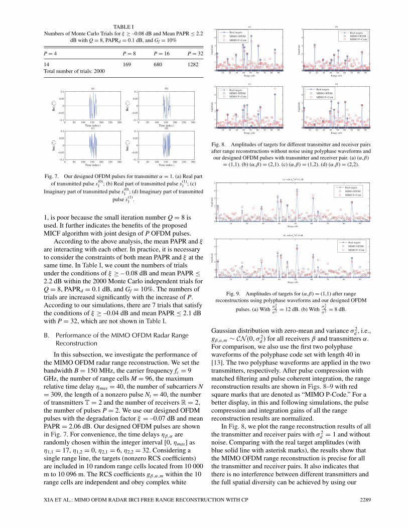
TABLE INumbers of Monte Carlo Trials for ξ ≥ –0.08 dB and Mean PAPR ≤ 2.2
dB with Q = 8, PAPRd = 0.1 dB, and Gf = 10%
P = 4 P = 8 P = 16 P = 32
14 169 680 1282Total number of trials: 2000
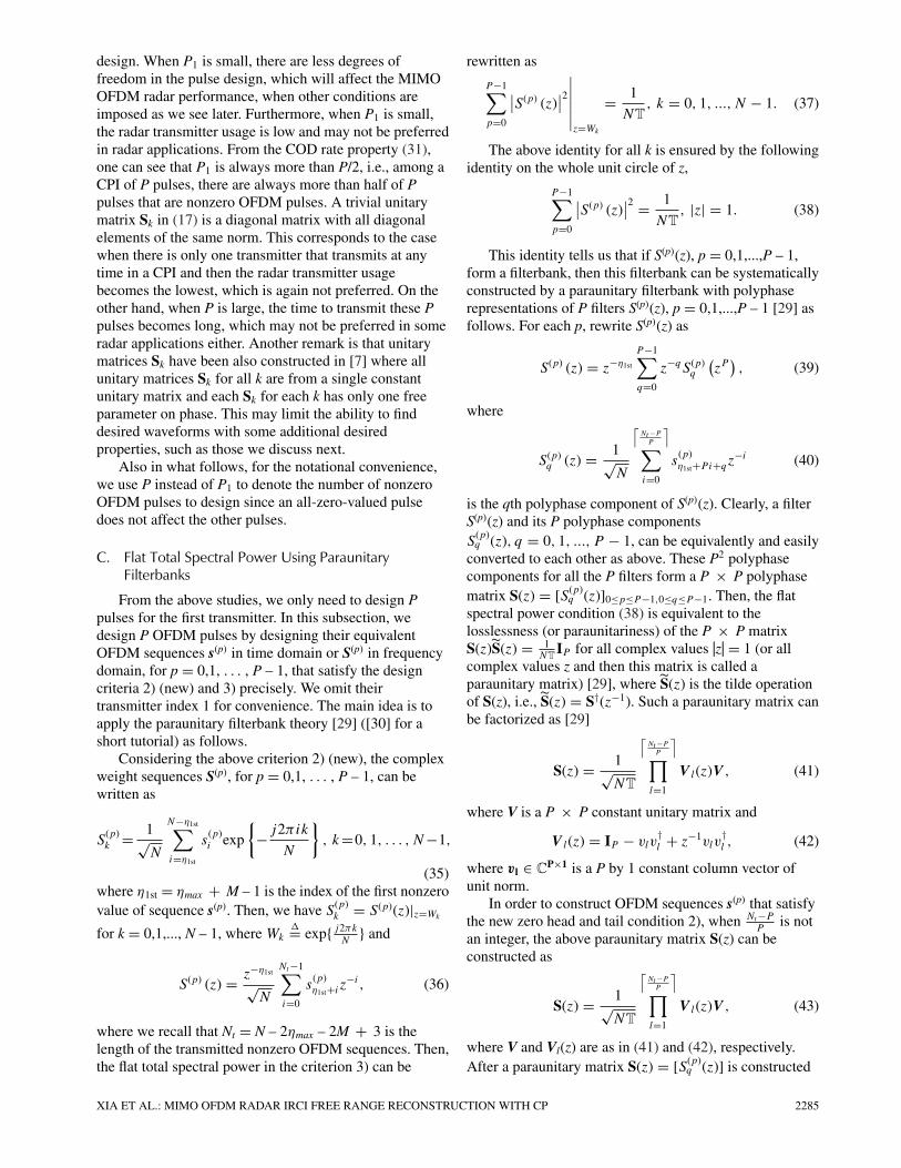
Fig. 7. Our designed OFDM pulses for transmitter α = 1. (a) Real partof transmitted pulse s
(0)1 ; (b) Real part of transmitted pulse s
(1)1 ; (c)
Imaginary part of transmitted pulse s(0)1 ; (d) Imaginary part of transmitted
pulse s(1)1 .
1, is poor because the small iteration number Q = 8 isused. It further indicates the benefits of the proposedMICF algorithm with joint design of P OFDM pulses.
According to the above analysis, the mean PAPR and ξ
are interacting with each other. In practice, it is necessaryto consider the constraints of both mean PAPR and ξ at thesame time. In Table I, we count the numbers of trialsunder the conditions of ξ ≥ – 0.08 dB and mean PAPR ≤2.2 dB within the 2000 Monte Carlo independent trials forQ = 8, PAPRd = 0.1 dB, and Gf = 10%. The numbers oftrials are increased significantly with the increase of P.According to our simulations, there are 7 trials that satisfythe conditions of ξ ≥ –0.04 dB and mean PAPR ≤ 2.1 dBwith P = 32, which are not shown in Table I.
B. Performance of the MIMO OFDM Radar RangeReconstruction
In this subsection, we investigate the performance ofthe MIMO OFDM radar range reconstruction. We set thebandwidth B = 150 MHz, the carrier frequency fc = 9GHz, the number of range cells M = 96, the maximumrelative time delay ηmax = 40, the number of subcarriers N= 309, the length of a nonzero pulse Nt = 40, the numberof transmitters T = 2 and the number of receivers R = 2,
the number of pulses P = 2. We use our designed OFDMpulses with the degradation factor ξ = –0.07 dB and meanPAPR = 2.06 dB. Our designed OFDM pulses are shownin Fig. 7. For convenience, the time delays ηβ ,α arerandomly chosen within the integer interval [0, ηmax] asη1,1 = 17, η1,2 = 0, η2,1 = 6, η2,2 = 32. Considering asingle range line, the targets (nonzero RCS coefficients)are included in 10 random range cells located from 10 000m to 10 096 m. The RCS coefficients gβ ,α ,m within the 10range cells are independent and obey complex white
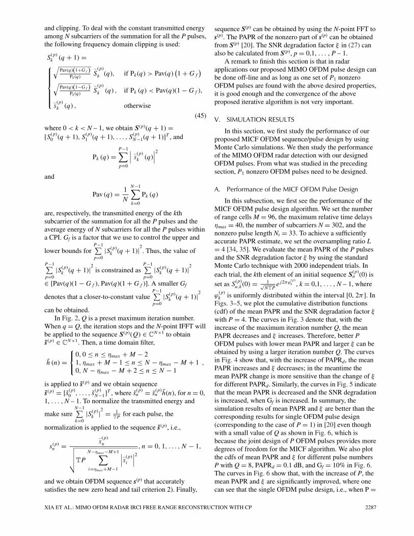
Fig. 8. Amplitudes of targets for different transmitter and receiver pairsafter range reconstructions without noise using polyphase waveforms andour designed OFDM pulses with transmitter and receiver pair. (a) (α,β)
= (1,1). (b) (α,β) = (2,1). (c) (α,β) = (1,2). (d) (α,β) = (2,2).
Fig. 9. Amplitudes of targets for (α,β) = (1,1) after rangereconstructions using polyphase waveforms and our designed OFDM
pulses. (a) Withσ 2d
σ 2 = 12 dB. (b) Withσ 2d
σ 2 = 8 dB.
Gaussian distribution with zero-mean and variance σ 2d , i.e.,
gβ,a,m ∼ CN (0, σ 2d ) for all receivers β and transmitters α.
For comparison, we also use the first two polyphasewaveforms of the polyphase code set with length 40 in[13]. The two polyphase waveforms are applied in the twotransmitters, respectively. After pulse compression withmatched filtering and pulse coherent integration, the rangereconstruction results are shown in Figs. 8–9 with redsquare marks that are denoted as “MIMO P-Code.” For abetter display, in this and following simulations, the pulsecompression and integration gains of all the rangereconstruction results are normalized.
In Fig. 8, we plot the range reconstruction results of allthe transmitter and receiver pairs with σ 2
d = 1 and withoutnoise. Comparing with the real target amplitudes (withblue solid line with asterisk marks), the results show thatthe MIMO OFDM range reconstruction is precise for allthe transmitter and receiver pairs. It also indicates thatthere is no interference between different transmitters andthe full spatial diversity can be achieved by using our
XIA ET AL.: MIMO OFDM RADAR IRCI FREE RANGE RECONSTRUCTION WITH CP 2289

Fig. 10. Amplitudes of targets for (α,β) = (1,1) after rangereconstructions using frequency division LFM waveforms and our
designed OFDM pulses. (a) Without noise. (b) Withσ 2d
σ 2 = 12 dB. (c)
Withσ 2d
σ 2 = 8 dB.
proposed MIMO OFDM radar. Meanwhile, the benefit ofthe IRCI free range reconstruction by using CP-basedOFDM radar still holds. However, because of the nonzerocross correlation (or nonorthogonality) between the twopolyphase waveforms as well as the range sidelobes of theautocorrelation functions, some targets cannot bereconstructed correctly as shown in Fig. 8, and thus, thespatial diversity cannot be clearly obtained by using thepolyphase waveforms. Moreover, the range reconstructionresults of some range cells without target by using thepolyphase waveforms are much larger than 0. We alsoconsider the range reconstruction performances forσ 2
d
σ 2 = 12 dB and 8 dB. Notice that, according to (34) andthe normalized transmitted energy constraint, the SNRs ofthe received signals are about –10.04 dB and –14.04 dB forσ 2
d
σ 2 = 12 dB and 8 dB, respectively. The simulation resultsfor the transmitter and receiver pair (α, β) = (1,1) areplotted in Fig. 9. The results show that the performancesof our proposed MIMO OFDM radar are better than thatby using the polyphase waveforms, especially for a larger
SNR, for example, when σ 2d
σ 2 = 12 dB.For further comparison, we also consider the
frequency division MIMO radar, in which eachtransmitted waveform is assigned an independent andnonoverlapped frequency band with bandwidth B. Thus,the orthogonality of the transmitted waveforms isguaranteed in this radar system despite time delays, but T
times more bandwidth (i.e., TB) is required. By usingLFM waveforms and the above simulation parameters, weobtain and plot the range reconstruction results in Fig. 10with red square marks that are denoted as “MIMOFD-LFM.” By comparing with the true target amplitudes,the results indicate that the performances of our proposedMIMO OFDM radar are obviously better than the MIMO
FD-LFM radar for the cases without noise and σ 2d
σ 2 = 12dB. It is because the IRCI across the range cells occurs byusing LFM waveforms, even through the cross correlation
can be completely avoided by using frequency division.The performances of MIMO OFDM and MIMO FD-LFM
are similar to each other for σ 2d
σ 2 = 8 dB. However, inMIMO FD-LFM the bandwidth requirement is 300 MHz,twice more. We believe that the IRCI will be more seriousby using LFM waveforms when more range cells areincluded in targets, and the benefit of our proposed MIMOOFDM radar will be more obvious.
VI. CONCLUSION
In this paper, we proposed a novel frequency-bandshared and sufficient CP-based MIMO OFDM radar rangereconstruction method by using our newly proposed anddesigned OFDM pulses that are in the same frequencyband but orthogonal to each other for every subcarrier inthe discrete frequency domain. This range reconstructionalgorithm with the orthogonality of the MIMO OFDMsignals can provide the advantage of avoiding theinterference between different transmitters, even whenthere are time delays among the signals from differenttransmitters, and achieving the full spatial diversity.Meanwhile, due to the sufficient CP insertion to eachpulse with the zero head and tail values in the discretetime domain, the range reconstruction is IRCI free and theproposed system does not have the energy redundancy.Our proposed range reconstruction is a joint pulsecompression and pulse coherent integration, after whichthe SNR was analyzed. We then proposed four designcriteria for multiple OFDM pulses. To achieve theorthogonality for every subcarrier in the discrete frequencydomain across multiple transmitters, COD were adopted,with which only non-zero-valued OFDM pulses for thefirst transmitter are needed to be designed. To maximizethe SNR, a closed-form solution was proposed by usingthe paraunitary filterbank theory. Considering the trade-offbetween the PAPR and the SNR degradation within therange reconstruction, we also proposed an MICF jointOFDM pulse design method to obtain OFDM pulses withlow PAPRs and insignificant SNR degradation. We finallypresented some simulations to demonstrate theperformance of the proposed OFDM pulse design method.By comparing with the frequency-band shared MIMOradar using polyphase code waveforms and frequencydivision MIMO radar using LFM waveforms, we providedsome simulations to illustrate the advantage, such as thefull spatial diversity and free IRCI, after the rangereconstruction, of the proposed MIMO OFDM radar.
This paper provides a framework on frequency-bandshared statistical MIMO OFDM radar with IRCI free andinter-transmitter-interference (ITI) free rangereconstruction. Some interesting research problemsremain. One of them is how to deal with the trade-offbetween the nonzero pulse number P1 and the total pulsenumber P in a CPI. The other one would be on how tosearch the parameters in the paraunitary matrix to satisfythe ideal flat spectral power criterion 3) and also havegood PAPR property, i.e., satisfy criterion 4).
2290 IEEE TRANSACTIONS ON AEROSPACE AND ELECTRONIC SYSTEMS VOL. 51, NO. 3 JULY 2015

As a final remark, this paper only considers statisticalMIMO radar where multiple OFDM pulses with sufficientCP are transmitted by each transmitter in a CPI. ColocatedMIMO OFDM radar has been recently considered in [36]where only one OFDM pulse with sufficient CP istransmitted in a CPI at each transmitter.
REFERENCES
[1] Tse, D., and Viswanath, P.Fundamentals of Wireless Communication. New York:Cambridge University Press, 2005.
[2] Biglieri, E., Calderbank, R., Constantinides, A., Goldsmith, A.,Paulraj, A., and Poor, H. V.MIMO Wireless Communications. New York: CambridgeUniversity Press, 2007.
[3] Haimovich, A., Blum, R., and Cimini, L.MIMO radar with widely separated antennas.IEEE Signal Processing Magazine, 25, 1 (2008), 116–129.
[4] Li, J., and Stoica, P.MIMO radar with colocated antennas.IEEE Signal Processing Magazine, 24, 5 (2007), 106–114.
[5] Li, J., and Stoica, P.MIMO Radar Signal Processing. New York: Wiley OnlineLibrary, 2008.
[6] Kim, J.-H., Younis, M., Moreira, A., and Wiesbeck, W.A novel OFDM chirp waveform scheme for use of multipletransmitters in SAR.IEEE Geoscience and Remote Sensing Letters, 10, 3 (2013),568–572.
[7] Wu, X., Kishk, A., and Glisson, A.MIMO-OFDM radar for direction estimation.IET Radar, Sonar Navigation, 4, 1 (2010), 28–36.
[8] Sit, Y., Sturm, C., Baier, J., and Zwick, T.Direction of arrival estimation using the MUSIC algorithm fora MIMO OFDM radar.In 2012 IEEE Radar Conference (RADAR), Atlanta, GA, May2012, pp. 0226–0229.
[9] Sen, S., and Nehorai, A.OFDM MIMO radar with mutual-information waveformdesign for low-grazing angle tracking.IEEE Transactions on Signal Processing, 58, 6 (2010),3152–3162.
[10] San Antonio, G., Fuhrmann, D., and Robey, F.MIMO radar ambiguity functions.IEEE Journal of Selected Topics in Signal Processing, 1, 1(2007), 167–177.
[11] Somaini, U.Binary sequences with good autocorrelation and crosscorrelation properties.IEEE Transactions on Aerospace and Electronic Systems,AES-11, 6 (1975), 1226–1231.
[12] Deng, H.Synthesis of binary sequences with good autocorrelation andcrosscorrelation properties by simulated annealing.IEEE Transactions on Aerospace and Electronic Systems, 32,1 (1996), 98–107.
[13] Deng, H.Polyphase code design for orthogonal netted radar systems.IEEE Transactions on Signal Processing, 52, 11 (2004),3126–3135.
[14] Khan, H., Zhang, Y., Ji, C., Stevens, C., Edwards, D., andO’Brien, D.Optimizing polyphase sequences for orthogonal netted radar.IEEE Signal Processing Letters, 13, 10 (2006), 589–592.
[15] He, H., Stoica, P., and Li, J.Designing unimodular sequence sets with goodcorrelations-Including an application to MIMO radar.
IEEE Transactions on Signal Processing, 57, 11 (2009),4391–4405.
[16] Song, X., Zhou, S., and Willett, P.Reducing the waveform cross correlation of MIMO radar withspace-time coding.IEEE Transactions on,Signal Processing, 58, 8 (2010),4213–4224.
[17] Xu, L., and Liang, Q.Zero correlation zone sequence pair sets for MIMO radar.IEEE Transactions on Aerospace and Electronic Systems, 48,3 (2012), 2100–2113.
[18] Jin, Y., Wang, H., Jiang, W., and Zhuang, Z.Complementary-based chaotic phase-coded waveforms designfor MIMO radar.IET Radar, Sonar Navigation, 7, 4 (2013), 371–382.
[19] Zhang, T., and Xia, X.-G.OFDM synthetic aperture radar imaging with sufficient cyclicprefix.IEEE Transactions on Geoscience and Remote Sensing, 53, 1(2015), 394–404.
[20] Zhang, T., Xia, X.-G., and Kong, L.IRCI free range reconstruction for SAR imaging with arbitrarylength OFDM pulse.IEEE Transactions on Signal Processing, 62, 18 (2014),4748–4759.
[21] Alamouti, S.A simple transmit diversity technique for wirelesscommunications.IEEE Journal on Selected Areas in Communications, 16, 8(1998), 1451–1458.
[22] Tarokh, V., Jafarkhani, H., and Calderbank, A.Space-time block codes from orthogonal designs.IEEE Transactions on Information Theory, 45, 5 (1999),1456–1467.
[23] Su, W., and Xia, X.-G.On space-time block codes from complex orthogonal designs.Wireless Personal Communications, 25, 1 (2003),1–26.
[24] Liang, X.-B., and Xia, X.-G.On the nonexistence of rate-one generalized complexorthogonal designs.IEEE Transactions on Information Theory, 49, 11 (2003),2984–2988.
[25] Wang, H., and Xia, X.-G.Upper bounds of rates of complex orthogonal space-timeblock codes.IEEE Transactions on Information Theory, 49, 10 (2003),2788–2796.
[26] Liang, X.-B.Orthogonal designs with maximal rates.IEEE Transactions on Information Theory, 49, 10 (2003),2468–2503.
[27] Su, W., Xia, X.-G., and Liu, K.A systematic design of high-rate complex orthogonalspace-time block codes.IEEE Communications Letters, 8, 6 (2004), 380–382.
[28] Lu, K., Fu, S., and Xia, X.-G.Closed-form designs of complex orthogonal space-time blockcodes of rates (k + 1)/(2k) for 2k–1 or 2k transmit antennas.IEEE Transactions on Information Theory, 51, 12 (2005),4340–4347.
[29] Vaidyanathan, P. P.Multirate Systems and Filter Banks. Englewood Cliffs, NJ:Prentice-Hall, 1993.
[30] Xia, X.-G.Multirate filterbanks.In Wiley Encyclopedia of Electrical and ElectronicsEngineering, vol. 14, J. G. Webster, Ed. New York: Wiley,1999, pp. 35–51.
XIA ET AL.: MIMO OFDM RADAR IRCI FREE RANGE RECONSTRUCTION WITH CP 2291

[31] Skolnik, M. I.Introduction to Radar Systems. New York: McGraw-Hill,2001.
[32] Prasad, R.OFDM for Wireless Communications Systems. Boston: ArtechHouse, 2004.
[33] Fishler, E., Haimovich, A., Blum, R., Cimini, L., Chizhik, D.,and Valenzuela, R.Spatial diversity in radars-models and detection performance.IEEE Transactions on Signal Processing, 54, 3 (2006),823–838.
[34] Armstrong, J.Peak-to-average power reduction for OFDM by repeated
clipping and frequency domain filtering.Electronics Letters, 38, 5 (2002),246–247.
[35] Han, S. H., and Lee, J. H.An overview of peak-to-average power ratio reductiontechniques for multicarrier transmission.IEEE Wireless Communications, 12, 2 (2005),56–65.
[36] Cao, Y.-H., Xia, X.-G., and Wang, S.-H.IRCI free co-located MIMO radar based on sufficient cyclicprefix OFDM waveforms.IEEE Transactions on Aerospace and Electronic Systems, tobe published (2015).
Xiang-Gen Xia (M’97—S’00—F’09) received his B.S. degree in mathematics fromNanjing Normal University, Nanjing, China, and his M.S. degree in mathematics fromNankai University, Tianjin, China, and his Ph.D. degree in electrical engineering fromthe University of Southern California, Los Angeles, in 1983, 1986, and 1992,respectively.
He was a Senior/Research Staff Member at Hughes Research Laboratories, Malibu,CA, during 1995-1996. In September 1996, he joined the Department of Electrical andComputer Engineering, University of Delaware, Newark, where he is the Charles BlackEvans Professor. His current research interests include space-time coding, MIMO andOFDM systems, digital signal processing, and synthetic aperture radar (SAR) andinverse synthetic aperture radar (ISAR) imaging.
Dr. Xia has over 300 refereed journal articles published and accepted, is the holderof seven U.S. patents, and is the author of the book, Modulated Coding for IntersymbolInterference Channels (Marcel Dekker, 2000). He received the National ScienceFoundation (NSF) Faculty Early Career Development (CAREER) Program Award in1997, the Office of Naval Research (ONR) Young Investigator Award in 1998, and theOutstanding Overseas Young Investigator Award from the National Nature ScienceFoundation of China in 2001. He also received the Outstanding Junior Faculty Award ofthe Engineering School of the University of Delaware in 2001. He is currently servingand has served as an Associate Editor for numerous international journals includingIEEE Transactions on Signal Processing, IEEE Transactions on WirelessCommunications, IEEE Transactions on Mobile Computing, and IEEE Transactions onVehicular Technology. He was Technical Program Chair of the Signal ProcessingSymposium, Globecom 2007 in Washington, D. C., and the General Co-Chair ofInternational Conference on Acoustics, Speech and Signal Processing (ICASSP) 2005in Philadelphia, PA.
Tianxian Zhang received his B.S. degree from the University of Electronic Scienceand Technology of China (UESTC) in 2009. He is now working toward his Ph.D.degree on signal and information processing at UESTC.
From October 2012 to October 2014, he was a visiting student researcher at theUniversity of Delaware. His current research interests include radar and statisticalsignal processing, and synthetic aperture radar (SAR) systems.
2292 IEEE TRANSACTIONS ON AEROSPACE AND ELECTRONIC SYSTEMS VOL. 51, NO. 3 JULY 2015

Lingjiang Kong was born in 1974. He received the B.S., M.S., and Ph.D. degrees fromthe University of Electronic Science and Technology of China (UESTC) in 1997, 2000,and 2003, respectively.
From September 2009 to March 2010, he was a visiting researcher with theUniversity of Florida. He is currently a professor with the School of ElectronicEngineering, University of Electronic Science and Technology of China (UESTC). Hisresearch interests include multiple-input multiple-output (MIMO) radar, through thewall radar, and statistical signal processing.
XIA ET AL.: MIMO OFDM RADAR IRCI FREE RANGE RECONSTRUCTION WITH CP 2293