Erosion As Pollution: The net economic and shoreline effects of coastal structures

Shoreline Management Plan 2019
Ausable Bayfield Conservation Authority
12646.201 Appendix B
Considerations for Shoreline Protection Structures
Ausable Bayfield Conservation Authority
Considerations for Shoreline Protection Structures
December 7 2017 | 12646.101
Ausable Bayfield Conservation Authority
Considerations for Shoreline Protection Structures
© 2017 W.F. Baird & Associates Coastal Engineers Ltd. (Baird) All Rights Reserved. Copyright in the whole and every part of this document, including any data sets or outputs that accompany this report, belongs to Baird and may not be used, sold, transferred, copied or reproduced in whole or in part in any manner or form or in or on any media to any person without the prior written consent of Baird.
This document was prepared by W.F. Baird & Associates Coastal Engineers Ltd. for Ausable Bayfield Conservation Authority. The outputs from this document are designated only for application to the intended purpose, as specified in the document, and should not be used for any other site or project. The material in it reflects the judgment of Baird in light of the information available to them at the time of preparation. Any use that a Third Party makes of this document, or any reliance on decisions to be made based on it, are the responsibility of such Third Parties. Baird accepts no responsibility for damages, if any, suffered by any Third Party as a result of decisions made or actions based on this document.
12646.101 Page i
Prepared for: Prepared by:
Ausable Bayfield Conservation Authority
71108 Morrison Line
Exeter, ON N0M 1S5
W.F. Baird & Associates Coastal Engineers Ltd.
For further information, please contact
Fiona Duckett, P.Eng. at +1 905 845 5385
www.baird.com
12646.101
Z:\Shared With Me\QMS\2017\Reports_2017\12646.101.R2.Rev0_Final Report.docx
Revision Date Status Comments Prepared Reviewed Approved
Rev A 25/10/2017 Draft For Review by ABCA FJLD MOK FJLD
Rev 1 01/12/2017 Final FJLD MOK FJLD
Ausable Bayfield Conservation Authority Considerations for Shoreline Protection Structures
12646.101 Page ii
Executive Summary
Background and Purpose
This document updates the Ausable Bayfield Conservation Authority (ABCA) report, Considerations for Shore Protection Structures (Baird, 1994). It is a component of the Conservation Authority’s shoreline management planning process.
The document is intended to provide technical guidance and assistance to lakefront property owners, the ABCA and local municipalities with respect to shoreline protection, and is supported by the Great Lakes-St. Lawrence River System Technical Guide for Flooding, Erosion and Dynamic Beaches (MNR, 2001). The focus is engineered erosion protection for bluff shorelines subject to moderate to severe erosion.
Since 1994 there have been many changes along the ABCA shoreline. Development pressures on the shoreline have increased due to; increase in demand for shoreline property; increase in the size of houses; increase in conversion of cottages to year-round use; and increase in investment in larger scale shore protections works. Approaches to shoreline management planning are also evolving and there is an growing recognition of the cumulative impacts of shore protection on downdrift shorelines. The Provincial Policy Statement (PPS) (MMAH, 2014) directs the ABCA to ensure that no new hazards are created, existing hazards are not aggravated, and adverse environmental impacts do not result due to development at the shoreline. The ABCA SMP is under review and policies regarding shore protection will be updated in the future.
ABCA Shoreline
The ABCA has jurisdiction over 60 km of Lake Huron shoreline extending from Towerline Road in Central Huron, to south of Port Franks. The shoreline north of Maple Grove subdivision is characterized by cohesive till bluffs, up to 18 m in height, fronted by narrow beaches of mixed sand and gravel. Long term average annual recession rates vary from less than 0.3 m/yr to greater than 1 m/yr. The shoreline south of Maple Grove subdivision is characterized by sandy beaches and dune systems. The northern shoreline is largely erosional and supplies sediment to the southern shoreline which is largely depositional.
Development along the ABCA shoreline includes over 60 major residential subdivisions, as well as the Village of Bayfield, the Village of Grand Bend, and Port Franks. In general, the residential subdivisions are located on the tableland behind the top of the bluff, although there are isolated cases where development has taken place on a beach terrace lakeward of the base of the bluff. Many property owners have installed shoreline protection structures of varying type and quality. Groynes and seawalls are the predominant structures, although revetments have been constructed at some locations.
Coastal Conditions
This report includes a review of coastal conditions that govern the design of shoreline protection works including water levels, waves, nearshore lakebed erosion, ice, geotechnical considerations and climate change. The design wave height incident on a shoreline protection structure along the ABCA shoreline will be depth limited, meaning the magnitude of the largest wave which can impact the structure is controlled by the water depth in front of the structure. Water level variations and long-term erosion of the nearshore lakebed must therefore be considered in establishing the design water depth and design wave height for a structure. Simplified approaches for estimating nearshore lakebed erosion, water level data and wave data for the ABCA shoreline are discussed.

Ausable Bayfield Conservation Authority Considerations for Shoreline Protection Structures
12646.101 Page iii
The different geological characteristics and recession rates along the ABCA shoreline are important considerations for shore protection design. From the perspective of understanding the shoreline erosion mechanism and the different types of shoreline protection structures that may be effective in reducing erosion, three shoreline conditions were identified: severe to moderate shoreline recession (average annual recession rates greater than 0.3 m/yr); minor shoreline recession (average annual recession rates less than 0.3 m/yr); and stable shorelines (no recession or accreting).
Where recession is severe to moderate, protection of the shoreline will be costly. As erosion of the nearshore lakebed will continue in the future, the structure must be designed to have a base, or toe, embedded at a sufficient depth to prevent undermining, and must be designed to resist the larger waves to which it will eventually be exposed. Flanking is a concern where adjacent properties are unprotected. Similar issues must be considered for shorelines with minor recession, although the structure will have a longer design life, all things being equal, due to slower erosion of the lakebed. For stable shorelines, the objective is to prevent wave runup on the beach from reaching the bluff during periods of high water levels and there is generally not a need for shore protection.
Recommendations for Shore Protection
Recommendations are made with respect to the selection, design and implementation of shore protection structures along the ABCA shoreline. Wherever possible, the use of development setbacks, the relocation of existing buildings, and the acquisition of shoreline property by public organizations (i.e., the townships, municipalities and ABCA) should be utilized rather than the construction of shore protection structures. Structural approaches reviewed include: groynes, revetments, seawalls, beach nourishment and offshore breakwaters. Recommendations for shore protection are provided and are summarized in the following paragraphs.
Regional beach nourishment is a desirable protection alternative with respect to maintaining/enhancing coastal processes. However, it is unlikely that a regional beach nourishment scheme could be implemented in the foreseeable future due to the detailed design requirements, the high capital and maintenance costs and the need for cooperation between several agencies and property owners.
In areas subject to moderate to severe long-term recession (average recession rate > 0.3 m/yr), an engineered rubble mound (armour stone) revetment can be designed to provide protection. However, it is costly and in the long term, erosion of the nearshore lakebed will continue. There are also concerns with beach access.
Reflective seawalls, such as steel sheet pile walls, are not recommended for erosion protection anywhere along the ABCA shoreline. Seawalls, due to their steep, impermeable and generally smooth face, cause more wave reflection, resulting in increased scour and the risk of undermining at the toe of the structure. Because of this, seawalls may fail catastrophically if not designed correctly. Seawalls also require higher crest elevations than permeable revetments to provide a similar level of protection against wave overtopping.
In general, groynes will not provide adequate protection in areas subject to moderate to severe long-term recession. Permitting may also be challenging due to concerns with impacts to adjacent properties.
Offshore breakwaters containing imported beach fill may be considered by the Village of Bayfield for the area to the south of the harbour. This type of approach is relatively expensive, but can provide significant recreational benefits as well as effective erosion protection.
Ausable Bayfield Conservation Authority Considerations for Shoreline Protection Structures
12646.101 Page iv
Discussions presented in this report are preliminary in nature. Final designs should be developed on a site-specific basis, within the overall framework of the Shoreline Management Plan (SMP), by a licensed Professional Engineer with experience and qualifications in coastal engineering.
Recommendations for Future Work
The following recommendations are provided for additional follow-up work to support shoreline management planning at ABCA:
1. ABCA should update policies and procedures for dealing with shore protection along the ABCA shoreline to reflect the policy statements in the PPS (MMAH, 2014) and direction in the Technical Guide (MNR, 2001). This would include updating the information required to accompany applications for shore protection, to ensure that the ecosystem and coastal processes are not adversely impacted and that negative impacts on other shoreline properties are not created. It is recommended that ABCA require shore protection to be designed by a licensed Professional Engineer with experience and qualifications in coastal engineering.
2. The Inventory of Erosion Control Structures on Lake Huron (ABCA, 1990) should be updated with future changes tracked based on permits issued.
3. It is recommended that the sediment budget (Reinders, 1989), be updated to provide improved understanding of the impacts of shore protection on downdrift beaches. This would follow the updated structures inventory and should reflect updated shoreline erosion rates and an assessment of bypassing at Goderich, Bayfield and Grand Bend. It should also include an assessment of long term beach stability at the Pinery and Ipperwash.
4. The annual oblique aerial photography collected by ABCA is beneficial to shoreline management planning and should continue.

Ausable Bayfield Conservation Authority Considerations for Shoreline Protection Structures
12646.101 Page v
Table of Contents
1. Introduction ............................................................................................................................. 1
1.1 Purpose 1
1.2 Changes Since 1994 1
1.3 Legislative Authority and Policy 2
1.4 Shoreline Management Planning at ABCA 2
2. Shoreline Description ............................................................................................................. 3
2.1 Introduction 3
2.2 Geology 3
2.3 ABCA Shoreline Characteristics 5
2.4 Shoreline Processes 6
2.4.1 Sub-cell 1 - Goderich Harbour to St. Christopher’s Beach 7
2.4.2 Sub-cell 2 – St. Christopher’s Beach to Bayfield Harbour 7
2.4.3 Sub-cell 3 - Bayfield Harbour to Maple Grove Subdivision 7
2.4.4 Sub-cell 4 - Maple Grove Subdivision to Kettle Point 9
2.5 Shoreline Development Overview 9
3. Design Conditions ............................................................................................................... 10
3.1 Water Levels 10
3.2 Nearshore Lakebed Erosion 12
3.3 Waves 14
3.4 Ice Conditions 16
3.5 Geotechnical Considerations 17
3.6 Climate Change Considerations for Design 17
4. Considerations for Shore Protection ................................................................................ 19
4.1 Introduction 19
4.2 Severe Shoreline Erosion and Bluff Recession 19

Ausable Bayfield Conservation Authority Considerations for Shoreline Protection Structures
12646.101 Page vi
4.3 Moderate Shoreline Erosion and Bluff Recession 20
4.4 Minor Shoreline Erosion and Bluff Recession 20
4.5 Stable Shoreline and Bluff 21
4.6 Summary 21
5. Structural Shore Protection Approaches ......................................................................... 23
5.1 Introduction 23
5.2 Existing Shore Protection Structures 23
5.3 Groynes 24
5.3.1 Discussion 24
5.3.2 Application Along ABCA Shoreline 25
5.3.3 Design Features 25
5.4 Revetments 26
5.4.1 Discussion 26
5.4.2 Application Along ABCA Shoreline 27
5.4.3 Design Features 27
5.5 Seawalls 28
5.5.1 Discussion 28
5.5.2 Application to ABCA Shoreline 29
5.6 Beach Nourishment 29
5.6.1 Discussion 29
5.6.2 Application to ABCA Shoreline 30
5.7 Offshore Breakwaters 31
5.7.1 Discussion 31
5.7.2 Application to ABCA Shoreline 32
6. Implementation .................................................................................................................... 34
6.1 Shoreline Management Plan and Considerations for Shore Protection 34

Ausable Bayfield Conservation Authority Considerations for Shoreline Protection Structures
12646.101 Page vii
6.2 Ownership 34
6.3 Permits and Approvals 34
6.4 Community Approach 35
6.5 Preparation of a Final Design 36
6.6 Construction 37
6.7 Monitoring and Maintenance 37
7. Recommendations .............................................................................................................. 38
7.1 Prevention versus Protection 38
7.2 Protection Alternatives 38
7.3 Implementation 39
7.4 Future Work 39
8. References ............................................................................................................................ 41
Shoreline Reaches from Goderich to Kettle Point (from Reinders, 1989)
Water Level Analysis
Nearshore Lakebed Erosion Summary of Methodology
ABCA Permit Applications for Shore Protection (as of September 14, 2017)
Tables
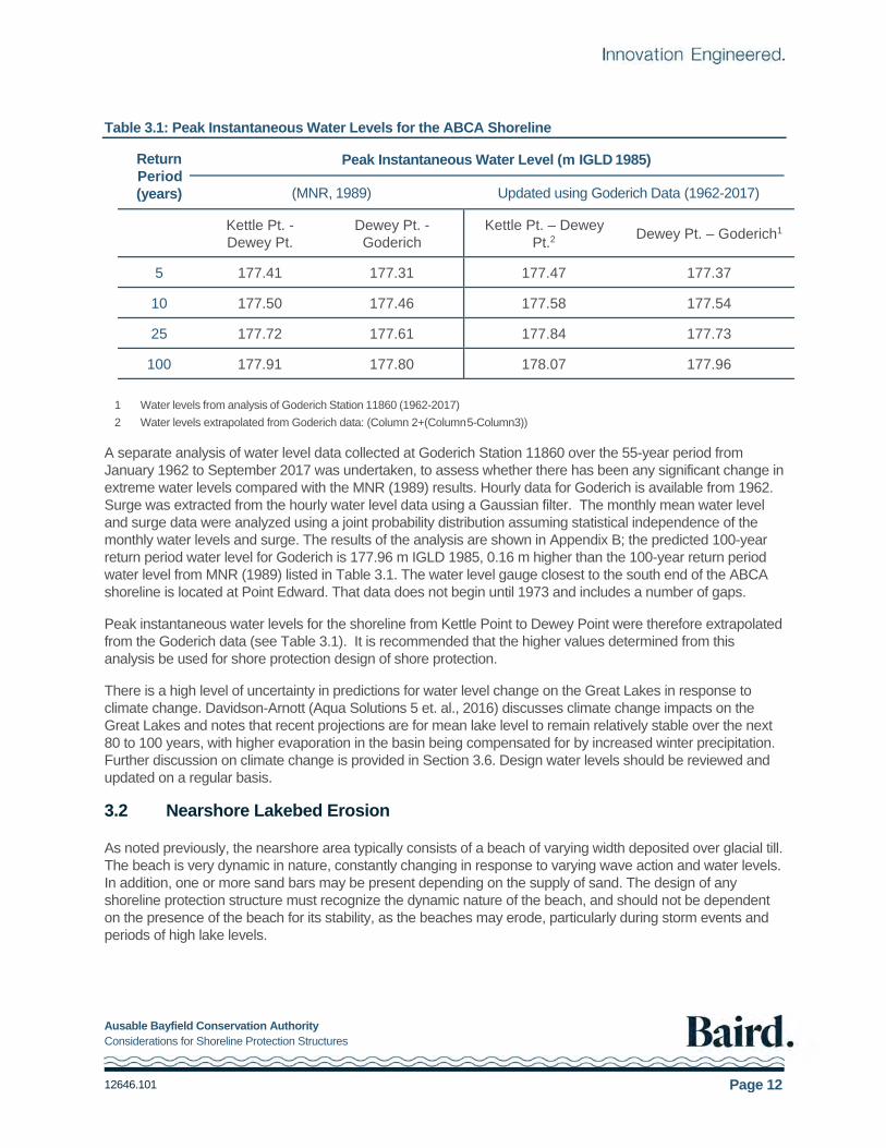
Table 3.1: Peak Instantaneous Water Levels for the ABCA Shoreline ......................................................... 12
Table 3.2: Erosion of the Nearshore Lakebed for Typical Nearshore Profile (for preliminary design only) . 14
Table 3.3: Example Calculation of Depth Limited Design Wave (for preliminary design only) ..................... 16
Figures
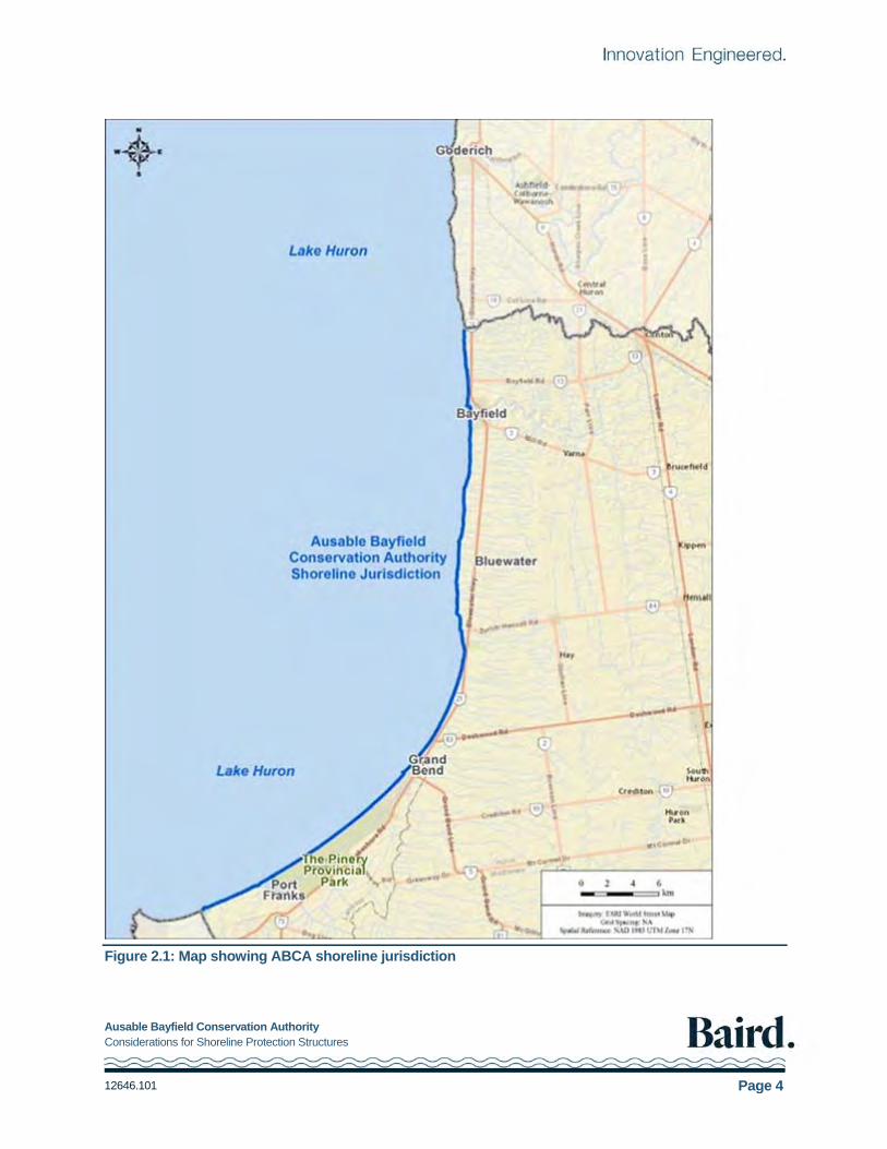
Figure 2.1: Map showing ABCA shoreline jurisdiction ......................................................................................4
Ausable Bayfield Conservation Authority Considerations for Shoreline Protection Structures
12646.101 Page viii
Figure 2.2: Schematic cross-section through east shore of Lake Huron (from Reinders, 1989) ....................5
Figure 2.3: ABCA Shoreline showing littoral cell and sub-cells ........................................................................8
Figure 3.1: Lake Huron monthly mean lake levels (1918 to 2017) ................................................................ 10
Figure 3.2: Seasonal water level fluctuations on Lake Huron (from the Canadian Hydrographic Service Monthly Water Level Bulletin) ....................................................................................................................................... 11
Figure 3.3: Schematic diagram of nearshore profile erosion ......................................................................... 13
Figure 3.4: Deepwater extreme wave height analysis (WIS Data: 1961 to 2014) ........................................ 15
Figure 4.1: Shore erosion – three typical conditions along ABCA shoreline ................................................. 22
Figure 5.1: Plan view of typical groyne field ................................................................................................... 25
Figure 5.2: Typical armour stone revetment section ...................................................................................... 27
Figure 5.3: Schematic showing concrete seawall .......................................................................................... 29
Figure 5.4: Plan and cross-section showing beach nourishment .................................................................. 30
Figure 5.5: Offshore breakwater concept showing emerged, low crest and nearshore reef alternatives .... 33
Ausable Bayfield Conservation Authority Considerations for Shoreline Protection Structures
12646.101 Page 1
1. Introduction
1.1 Purpose
This document updates the Ausable Bayfield Conservation Authority (ABCA) report, Considerations for Shore Protection Structures (Baird, 1994). It is a component of the Conservation Authority’s shoreline management planning process.
The report is intended to provide technical guidance and assistance to lakefront property owners, the ABCA and local municipalities with respect to shoreline protection. It is supported by the Great Lakes-St. Lawrence River System Technical Guide for Flooding, Erosion and Dynamic Beaches (MNR, 2001). The focus of this document is engineered erosion protection for bluff shorelines subject to moderate to severe erosion. The document does not address non-engineered shore damage protection in any detail; this has been covered in numerous earlier publications, notably MNR (1986) and USACOE (1978, 1981, 2002). Nor does it address the dynamic beach shorelines within the ABCA jurisdiction, or non-structural protection such as slope drainage measures and vegetating the slope. The Provincial Policy Statement (PPS), (MMAH, 2014), does not permit development, including shore protection on dynamic beaches.
The following sections provide discussion on the shoreline characteristics and processes within the jurisdiction of the ABCA, design considerations and criteria for erosion protection structures, and a summary of conceptual alternatives. Recommendations are made for the design and implementation (permitting, construction and monitoring) of erosion protection structures.
It is important to note that the information presented in this report is general in nature and intended for guidance purposes only. It is recommended that a qualified coastal engineer be retained to develop erosion protection designs for any specific site.
1.2 Changes Since 1994
Since 1994 there have been many changes along the ABCA shoreline. Development pressures on the shoreline have increased due to; increase in demand for shoreline property; increase in the size of houses; increase in conversion of cottages to year-round use; and increase in investment in larger scale shore protections works. There is also an increased demand for shoreline and beach access. With climate change, there is an expectation that the ice-free season will be longer, resulting in increased exposure of shorelines to wave action. This combined with more frequent and more intense storms is expected to result in the potential for increased shoreline erosion.
Approaches to shoreline management planning are also evolving. The PPS, (MMAH, 2014) requires the ABCA to ensure that no new hazards are created, existing hazards are not aggravated, and adverse environmental impacts do not result due to development at the shoreline. There is growing recognition of the cumulative impacts of shore protection on downdrift shorelines. Erosion of the cohesive bluffs provides a sediment source for downdrift beaches. When a shoreline is protected, this sediment source is lost. Although protection of an individual property may not have a large effect on downdrift shorelines, the cumulative effects can be significant.
Discussion in this document, regarding shore protection alternatives are general in nature. Future updates to the ABCA Shoreline Management Plan, may result in changes to policies regarding shore protection practices.

Ausable Bayfield Conservation Authority Considerations for Shoreline Protection Structures
12646.101 Page 2
1.3 Legislative Authority and Policy
The Conservation Authorities Act (CAA), Section 20, requires Conservation Authorities to design a program to further the conservation, restoration, development and management of natural resources that fall within their jurisdiction. In addition, Section 28 (1c) of the Act bestows regulatory responsibilities on Conservation Authorities, for areas under their jurisdiction, to make regulations prohibiting or regulating development if, in the opinion of the Authority, the control of flooding, erosion, dynamic beaches, pollution or the conservation of land may be affected by development, subject to the approval of the Minister.
Ontario Regulation 97/04 “Content of Conservation Authority Regulations under Subsection 28(1) of the Act: Development, Interference with Wetlands and Alterations to Shorelines and Watercourses” (i.e., Generic Regulation) was approved in May 2004. This Regulation established the content requirements to be met by a Conservation Authority under Subsection 28(1) of the Conservation Authorities Act. It stipulates the criteria by which each Conservation Authority must establish its updated regulated area or Regulation Limit.
Ontario Regulation 147/06 Development, Interference with Wetlands and Alterations to Shorelines and Watercourses was enacted in May 2006. It specifically enables ABCA to regulate the Great Lakes shoreline within its jurisdiction, up to the furthest landward extent of the aggregate of the flooding, erosion and dynamic beach hazards.
The PPS (MMAH, 2014) was issued under the Planning Act. The PPS states that Section 3 of the Planning Act “requires that decisions affecting planning matters ‘shall be consistent’ with policy statements issued under the Act”. Responsibility for providing input with respect to provincial interests under the PPS Section 3.1 – Natural Hazards is delegated to individual Conservation Authorities.
1.4 Shoreline Management Planning at ABCA
In 1988 the ABCA became the lead government commenting agency for land use planning as it related to flooding, erosion and dynamic beach hazards along the Lake Huron shoreline within its jurisdiction and the Conservation Authority was directed to prepare a Shoreline Management Plan. A number of supporting documents were developed including: Lake Huron Shoreline Processes Study (F.J. Reinders & Associates, 1989); Inventory of Coastal Structures on Lake Huron (ABCA, 1990); Considerations for Shore Protection Structures (Baird, 1994); and detailed 1:2000 scale regulatory mapping of the shoreline prepared by ABCA. In 1994 ABCA also developed a formal Shoreline Management Plan that was approved by the Board of Directors.
The Shoreline Management Plan was updated in 2000. In 2016, a Consultant Recommendation Report was prepared and the regulatory mapping with shoreline recession rates was updated (Aqua Solutions 5 Inc. et.al., 2016). Due to the public response, the Board passed a resolution on November 3, 2016, stating that it would not implement the ABCA Shoreline Development Guidelines of Section 7.8 in the report (pages 113 to 117), does not endorse the underlying principle of "managed retreat" and the outright prohibition of all shoreline protection works, and further, that the Board continue to endorse the use of policies in the 2000 SMP. The Board further directed staff to provide options to re-engage the public to update the 2000 SMP.
On February 16, 2017, staff presented the ABCA Board with a proposed method of re-engaging the public to move forward with updating the 2000 SMP. This process is underway.
Ausable Bayfield Conservation Authority Considerations for Shoreline Protection Structures
12646.101 Page 3
2. Shoreline Description
2.1 Introduction
The ABCA has jurisdiction over the 60 km length of Lake Huron shoreline between Towerline Road in Central Huron, north of the Village of Bayfield, and approximately 500 m north of Army Camp Road, south of Port Franks, as shown in Figure 2.1. This includes the shorelines of Central Huron (former Goderich Township), Bluewater (former Village of Bayfield, Stanley Township, Hay Township), South Huron (former Stephen Township), and Lambton Shores (former Village of Grand Bend, and part of Bosanquet Township including the community of Port Franks). First Nations land within this area is not under the jurisdiction of ABCA.
The shoreline can be generally classified into the northern steep bluff region, where erosion is an ongoing process, and the southern dynamic beach region, which is a deposition zone.
2.2 Geology
As a result of the glacial history of this area, the entire region is covered by deep glacial deposits. A schematic cross-section through the eastern shoreline of Lake Huron is presented in Figure 2.2, and indicates the presence of bedrock overlain by Rannoch till, which is in tum overlain by St. Joseph till.
The tills contain differing proportions of sand and gravel in the soil matrix. The Rannoch till is more resistant to wave action because of its relatively high gravel content, and has significantly affected the evolution of the Lake Huron shoreline. Lag deposits of coarse gravel, armour the exposed surface of the lakebed. These more resistant shallow shelves, cause waves to break and dissipate their wave energy offshore, reducing the exposure of the shoreline to wave induced erosion. It is possible that the two small headlands at Rocky Point and Dewey Point occur because of Rannoch till outcrops in the nearshore, which are more resistant to erosion than the adjacent shorelines. The St. Joseph till contains a smaller proportion of gravel than the Rannoch till, and is thus, less erosion resistant. Most of the exposed bluffs along the ABCA shoreline and nearshore lakebed consists of St. Joseph till.
The response of the shoreline to wave action depends on the composition of the soil at the shoreline and on the nearshore lakebed. The presence of exposed Rannoch till on the nearshore lakebed and at the base of the bluff results in a relatively stable (erosion resistant) shoreline, while the presence of St. Joseph till on the nearshore lakebed and at the base of the bluff results in an eroding shoreline (and nearshore lakebed).
Erosion of the bluffs and nearshore lakebed supplies sediment (clay, silt, sand and gravel) to the shore zone. These materials are transported by wave action and currents. The finer sediments (clay and silt particles) are carried in suspension, and tend to deposit offshore in deep water, while the coarser sediments (sand and gravel) are transported along the shoreline and form beaches, dunes and nearshore bars. Near Grand Bend, the till become buried by the sand deposits and the shoreline is dominated by dynamic sand beaches and dunes. The stability of these beaches is dependent on the supply of sand from bluff and nearshore lakebed erosion, gully erosion and rivers in the northern bluff section of the ABCA shoreline.
Ausable Bayfield Conservation Authority Considerations for Shoreline Protection Structures
12646.101 Page 4
Figure 2.1: Map showing ABCA shoreline jurisdiction

Ausable Bayfield Conservation Authority Considerations for Shoreline Protection Structures
12646.101 Page 5
Figure 2.2: Schematic cross-section through east shore of Lake Huron (from Reinders, 1989)
2.3 ABCA Shoreline Characteristics
The ABCA shoreline is divided into a northern section (north of Maple Grove subdivision) characterized by cohesive till bluffs, up to 18 m in height, fronted by narrow beaches of mixed sand and gravel. The shoreline south of Maple Grove subdivision is characterized by sandy beaches and dune systems. The northern shoreline is largely erosional and supplies sediment to the southern shoreline which is largely depositional.
Ausable Bayfield Conservation Authority Considerations for Shoreline Protection Structures
12646.101 Page 6
North of Maple Grove subdivision, the shoreline has a north-south orientation and consists of narrow sand beaches fronting till bluffs of moderate height (12 to 18 m). The bluff height tends to decrease to the south, and is in the order of 6 m high at Highway 83. Numerous gullies exist along this section of shoreline; these gullies have developed because of surface runoff, and may be stable or actively eroding. The bluffs have historically been eroding because of nearshore lakebed erosion and wave action undercutting the toe of the bluffs, which eventually leads to bluff instability and slumping. The slumped material or talus is then removed by wave action and the process continues. The extent of the recession varies; between 1935 and 1988, the long-term average recession rate along the majority of the ABCA shoreline was less than 0.3 m/yr (ABCA, 2000).
However, severe erosion occurred in two areas, specifically near Melena Heights and Lakewood Gardens/Sunny Ridge/Poplar Beach, with long term average recession rates in the order of 1 m/yr or more, over this same 53-year period. Other locations were subject to moderate recession, with long term average recession rates in the order of 0.5 m/yr.
As discussed above, the erosion of the bluffs is preceded by, and controlled by, a slow but continuing erosion of the nearshore lakebed. Although most of the visible erosion (i.e., bluff recession above the water line) occurs during periods of high water levels, the controlling process of nearshore erosion continues at all water levels, including during low water periods, however the distribution of erosion across the nearshore zone varies with fluctuating water levels.
The erosion of the bluffs and nearshore lakebed along this section of shoreline, as well as gully erosion and creeks, provide materials to the nearshore area. Of interest is the coarser material, specifically sands and gravels, which can form beaches and bars along the shoreline and thus provide some protection to the shoreline, as well as recreational benefits. Along the ABCA shoreline north of Maple Grove subdivision, it has been estimated (Reinders, 1989) that approximately 72% of the supply of sand and gravel to the nearshore area comes from bluff erosion, 10% from gully erosion, 17% from lakebed erosion, and 1% from creeks and rivers. This material is transported alongshore by wave-induced currents. The magnitude of this transport is a function of the wave conditions (principally wave height and direction), water depth close to the shoreline and availability of sediments. Due to the wave climate and shoreline orientation in this area, the net transport is from north to south, although reversals do occur in response to individual storms.
To the south of Maple Grove subdivision, the shoreline orientation changes from north-to-south to northeast-to- southwest, and the shoreline characteristics change from cohesive till bluffs to sand dunes. As a result of the change in shoreline orientation, the sediment transport rate decreases significantly, with recession rates becoming lower moving further south. The shoreline south of Beach O Pines has historically been a deposition zone. Over thousands of years this deposition has resulted in an extensive beach-dune system along the Grand Bend/Pinery/Ipperwash shoreline. The deposition of sand along this section of shoreline is offset to some extent by wind-blown (aeolian) losses from the beach to the dune and offshore losses. The stability of this beach-dune system is dependent on the supply of sand provided by updrift erosion processes, in particular bluff erosion between Grand Bend and Goderich. This is an important consideration for shoreline management planning.
2.4 Shoreline Processes
The ABCA shoreline lies within a littoral cell that extends from Goderich Harbour to Kettle Point. A littoral cell is a self-contained. coastal system, where the ongoing shoreline processes are not affected by the processes of the neighbouring cells. Sand is not transported between cells. As such, shoreline management of one cell can proceed independently of any other cell. A detailed description of shoreline processes is provided in Reinders (1989).

Ausable Bayfield Conservation Authority Considerations for Shoreline Protection Structures
12646.101 Page 7
The Goderich Harbour to Kettle Point littoral cell is divided into four littoral sub-cells as shown in Figure 2.3. There is some transport between sub-cells, although limited. Sub-cell 1 and a portion of sub-cell 2 are within the Maitland Valley Conservation Authority jurisdiction, and the southern part of sub-cell 4 is within the St. Clair Region Conservation Authority jurisdiction. The remainder is within ABCA jurisdiction. The four littoral sub-cells are discussed below.
2.4.1 Sub-cell 1 - Goderich Harbour to St. Christopher’s Beach
Between Goderich Harbour and the Goderich water treatment plant (Sub-cell 1 is outside the jurisdiction of the ABCA), the shoreline and bluffs are protected by a combination of exposed bedrock in the nearshore zone, beaches and shoreline protection structures, resulting in no significant bluff erosion. Limited erosion of the lakebed supplies approximately 1,000 m3/yr of sand to the nearshore area (Reinders, 1989). Sediment transport is negligible in this area due to the very limited supply and the sheltering effect of the Goderich Harbour structures, which are a barrier to longshore transport.
2.4.2 Sub-cell 2 – St. Christopher’s Beach to Bayfield Harbour
Between the Goderich water treatment plant and Bayfield Harbour (Sub-cell 2), the shoreline consists of cohesive bluffs fronted by narrow sand beaches. In 1990, it was estimated that approximately 30% of the shoreline within the ABCA's jurisdiction, in Sub-cell 2 (i.e., south of Concession Road 30), had been protected to some extent, generally using groynes and/or seawalls (ABCA, 1990). It is recommended that this data be updated to reflect current protection. Bluff recession ranges from less than 0.3 to 0.9 m/yr, with the highest recession in the Melena Heights area. Reinders (1989) estimated that bluff erosion supplies an average of 13,100 m3/yr of sand to the nearshore zone, and that gully and lakebed erosion supply approximately 4,100 and 2,800 m3/yr respectively.
A feature along this section of shoreline is the wide fillet beach which has accreted to the north of the Bayfield harbour structures (constructed in the late 1880's) and extends to the Jowett’s Grove area. The bluff and nearshore are protected by the fillet beach and the bluff is relatively stable. This beach has now achieved an equilibrium condition, and sand bypasses Bayfield Harbour and is transported south into the next sub-cell.
2.4.3 Sub-cell 3 - Bayfield Harbour to Maple Grove Subdivision
Between Bayfield Harbour and Maple Grove subdivision (Sub-cell 3), the shoreline consists of cohesive bluffs fronted by narrow sand beaches. ABCA (1990) estimated approximately 40% of this reach of shoreline was protected to some extent, with groynes and/or seawalls being the predominant structures. Bluff recession ranges from less than 0.3 to 1.3 m/yr, with the highest recession rates in the Lakewood Gardens/Sunny Ridge/Poplar Beach area. Bluff erosion supplies an average of approximately 32,600 m3/yr of sand to the nearshore zone, while gully and lakebed erosion supply approximately 4,200 and 7,400 m3/yr respectively (Reinders, 1989).

Ausable Bayfield Conservation Authority Considerations for Shoreline Protection Structures
12646.101 Page 8
Figure 2.3: ABCA Shoreline showing littoral cell and sub-cells

Ausable Bayfield Conservation Authority Considerations for Shoreline Protection Structures
12646.101 Page 9
Features along this section of shoreline include Rocky Point and Dewey Point; both are headlands projecting into the lake relative to the adjacent shorelines. As noted in Section 2.2, the long-term stability of these points relative to the adjacent shoreline is due to the presence of hard Rannoch till on the nearshore lakebed. Of interest to shoreline management is the development of cottages on a beach terrace at the base of the bluff (see for example Drysdale Beach), in addition to the more typical development on tableland at the top of bluff.
2.4.4 Sub-cell 4 - Maple Grove Subdivision to Kettle Point
Between Maple Grove subdivision and Kettle Point (Sub-cell 4), the shoreline consists of some relatively wide beaches fronting sand dunes. This reach of shoreline represents the deposition zone for the material which has been eroded from the bluffs, gullies and lakebed along the "updrift" shoreline to the north.
Over thousands of years, the deposition of sand along this reach of shoreline has resulted in the present day fully-developed beach-dune system. However, a comparison of shoreline conditions in 1935 and 1988 indicates that although the dune face has been relatively stable, the beach width has decreased substantially over this 53-year period. This change may be in part due to beach response to different water level and wave conditions in periods preceding the two surveys: the 1935 survey was completed following several years of very low lake levels, while the 1988 survey was completed shortly after the record high lake levels of 1985-1986. In addition, the 1935 survey was completed in August following a relatively calm summer while the 1988 survey was completed in April following a stormy fall/winter season. Both factors would lead to a narrower beach in 1988, as indicated by the survey results. It is possible however, that a net loss of sediment from the Pinery/Ipperwash beach system has occurred since 1935 due to a negative sediment budget (sand losses exceeding sand supply). Construction of the Goderich Harbour in 1916 would have reduced the supply of sand to this area, as well as possible losses to deep water caused by the harbour structures at Bayfield and Grand Bend. Additional studies including historical aerial imagery comparisons with more recent imagery, including adjustment for water level is recommended to update recession rates.
Similar to Bayfield, a fillet beach has developed to the north of the Grand Bend Harbour structures (built in 1904). This beach extends to the Maple Grove area, and appears to have reached an equilibrium condition such that sand is now bypassing the harbour structures to be deposited further downdrift. Limited shoreline protection has been constructed to the north of the harbour, while extensive protection has been constructed to the south of the harbour, particularly within the Village limits. This protection consists of groynes, seawalls and revetments intended to limit erosion of the dune during periods of high water.
A more detailed description of each of the four subcells (from Reinders, 1989) is presented in Appendix A.
2.5 Shoreline Development Overview
Development along the ABCA shoreline includes over 60 major residential subdivisions, as well as the Village of Bayfield, the Village of Grand Bend, and Port Franks. In general, the residential subdivisions are located on the tableland behind the top of the bluff, although there are isolated cases where development has taken place on a beach terrace in front (i.e., lakeward) of the base of the bluff. The residential subdivisions range in size from less than 10 residential properties to over 60 properties, and generally consist of a row of dwellings parallel to the top of the bluff, with varying building setbacks; in many cases, a second row of development has also been constructed inland of the first row. Many of these residential subdivisions have installed shoreline protection structures of varying type and quality. Groynes and seawalls are the predominant structures, although revetments have been constructed at some locations. Shoreline protection tends to be more extensive near the urban centres, where development along the shoreline is more intensive. There are a few areas which have less intensive development (conservation areas, municipal parks and trailer parks), as well as some undeveloped areas, but they are the exception.

Ausable Bayfield Conservation Authority Considerations for Shoreline Protection Structures
12646.101 Page 10
3. Design Conditions
3.1 Water Levels
Lake Huron water levels fluctuate over short-term (hours to days), seasonal and long-term (multi-annual) time horizons. These fluctuations in water level are the result of inflows from Lake Superior through the St. Mary’s River, climatic conditions such as precipitation, evaporation, wind, pressure variation, runoff from the basin, and outflow through the St. Clair River. The outflow from Lake Superior is regulated at the locks at Sault Ste. Marie but there is no regulation at the outflow to the St. Clair River. On average, Lake Superior supplies approximately 28% of the inflow into Lake Huron, approximately 41% comes from precipitation (rain and snow) over the lake, and an estimated 31% comes from runoff. Nearly 70% of the output is flow down the St. Clair River and an estimated 30% is lost through evaporation (Aqua Solutions 5 et.al., 2016).
Monthly mean lake levels for the period 1918 to 2017 are shown in Figure 3.1. The most recent period of high lake levels was 1985-86, and the highest monthly mean water level is 177.50 m International Great Lakes Datum (IGLD) 1985, in October 1986. Water levels in this report are referenced to IGLD 1985. Chart Datum is 176.0 m IGLD 1985.The lowest monthly mean water level was175.58 m IGLD 1985, recorded in March 1964, giving a maximum range of close to 2 m. There was a sustained period of low water levels from 2000 to 2012, however the lowest monthly mean was marginally higher than the lowest value recorded in 1964. Studies have shown a lowering of water levels on Lake Huron in response to dredging in the St. Clair River in the late 1800’s and during periods in the 1900’s, see for example Baird (2005). The International Joint Commission (2009) concluded that lowering water levels due to increased conveyance in the St. Clair River is not ongoing and that climate is the main driver of lake level.
Due to the size of the Great Lakes and the limited discharge capacities of their outflow rivers, extreme high or low lake levels will generally persist for a period of years, however lake levels can change relatively quickly as was observed when water levels dropped from record highs to "normal" conditions following the 1985-1986 period of high water levels; and in 2014 to 2017 when water levels rose from the low levels that occurred between 2000 and 2012.
Figure 3.1: Lake Huron monthly mean lake levels (1918 to 2017)
Seasonal fluctuations in the lake level are associated with the annual weather patterns and ice cover limits evaporation. The lowest levels typically occur in the winter when most precipitation is snow and ice, while the highest lake levels typically occur in the summer following spring runoff. On Lake Huron, the average seasonal water level fluctuation is approximately 0.3 m but does vary from year to year. Figure 3.2 shows the seasonal

Ausable Bayfield Conservation Authority Considerations for Shoreline Protection Structures
12646.101 Page 11
fluctuations in the average, maximum and minimum monthly mean water levels on Lake Huron for 1918 and 2017. The highest and lowest monthly means are indicated in red and blue respectively, with the year of occurrence. The long-term average monthly mean is indicated in grey and the recorded monthly mean for 2016 and 2017 to date is shown in black, with the forecast range for the next several months in dashed lines.
Figure 3.2: Seasonal water level fluctuations on Lake Huron (from the Canadian Hydrographic Service Monthly Water Level Bulletin)
Short term (hours or days) fluctuations in the water level occur due to the passage of weather systems, with wind stress on the water surface and atmospheric pressure changes causing localized setups referred to as storm surge. Storm surge along the ABCA shoreline varies with the severity of the storm, wind direction and location along the shoreline.
The selection of a design water level is of critical importance to the design of a shoreline protection structure, as the wave height acting on a structure in shallow water adjacent to the shoreline will be limited by the depth of water. Higher water levels will allow larger waves to reach the structure, thus requiring more substantial structures. Similarly, future erosion of the nearshore lakebed will allow larger waves to reach structures adjacent to the shoreline, and must be considered in structure design.
The water level used for design purposes is determined based on consideration of several factors including the project life, the shore protection structure design life and the acceptable level of risk. This is discussed in some detail in the MNR Technical Guide (2001). The appropriate return period event is determined once the acceptable level of risk and design life have been specified. The province has established the minimum design water level as the 100-year flood level. The probability of this event occurring in any particular year is 1%.
A summary of peak instantaneous water levels (monthly mean plus storm surge) from MNR (1989) is presented in Table 3.1. These values are based on an analysis of water level data from 1918 to 1989. Water levels for Kettle Point to Dewey Point are based on values for Kettle Point from MNR (1989); water levels for Dewey Point to Goderich are based on values for Goderich.
Ausable Bayfield Conservation Authority Considerations for Shoreline Protection Structures
12646.101 Page 12
Table 3.1: Peak Instantaneous Water Levels for the ABCA Shoreline
Return Peak Instantaneous Water Level (m IGLD 1985) Period (years) (MNR, 1989) Updated using Goderich Data (1962-2017)
Kettle Pt. - Dewey Pt.
Dewey Pt. - Goderich
Kettle Pt. – Dewey Pt.2
Dewey Pt. – Goderich1
5 177.41 177.31 177.47 177.37
10 177.50 177.46 177.58 177.54
25 177.72 177.61 177.84 177.73
100 177.91 177.80 178.07 177.96
1 Water levels from analysis of Goderich Station 11860 (1962-2017)
2 Water levels extrapolated from Goderich data: (Column 2+(Column 5-Column3))
A separate analysis of water level data collected at Goderich Station 11860 over the 55-year period from January 1962 to September 2017 was undertaken, to assess whether there has been any significant change in extreme water levels compared with the MNR (1989) results. Hourly data for Goderich is available from 1962. Surge was extracted from the hourly water level data using a Gaussian filter. The monthly mean water level and surge data were analyzed using a joint probability distribution assuming statistical independence of the monthly water levels and surge. The results of the analysis are shown in Appendix B; the predicted 100-year return period water level for Goderich is 177.96 m IGLD 1985, 0.16 m higher than the 100-year return period water level from MNR (1989) listed in Table 3.1. The water level gauge closest to the south end of the ABCA shoreline is located at Point Edward. That data does not begin until 1973 and includes a number of gaps.
Peak instantaneous water levels for the shoreline from Kettle Point to Dewey Point were therefore extrapolated from the Goderich data (see Table 3.1). It is recommended that the higher values determined from this analysis be used for shore protection design of shore protection.
There is a high level of uncertainty in predictions for water level change on the Great Lakes in response to climate change. Davidson-Arnott (Aqua Solutions 5 et. al., 2016) discusses climate change impacts on the Great Lakes and notes that recent projections are for mean lake level to remain relatively stable over the next 80 to 100 years, with higher evaporation in the basin being compensated for by increased winter precipitation. Further discussion on climate change is provided in Section 3.6. Design water levels should be reviewed and updated on a regular basis.
3.2 Nearshore Lakebed Erosion
As noted previously, the nearshore area typically consists of a beach of varying width deposited over glacial till. The beach is very dynamic in nature, constantly changing in response to varying wave action and water levels. In addition, one or more sand bars may be present depending on the supply of sand. The design of any shoreline protection structure must recognize the dynamic nature of the beach, and should not be dependent on the presence of the beach for its stability, as the beaches may erode, particularly during storm events and periods of high lake levels.

Ausable Bayfield Conservation Authority Considerations for Shoreline Protection Structures
12646.101 Page 13
In addition, the design of shoreline protection structures must consider the slow, but ongoing, erosion of the underlying cohesive nearshore lakebed. While the erosion rate at any given location on the profile will vary with water level fluctuations and amount of sand cover, erosion of the lakebed will occur during periods of low
lake levels, as well as during periods of average and high lake levels. The erosion may be insignificant over the short term, but may have significant implications to shoreline protection in the long term. Specifically, erosion of the nearshore lakebed in front of a shoreline protection structure may result in undermining of the structure, leading to damage and perhaps failure of the structure. In addition, this process will result in deeper water in front of the structure, thus allowing larger waves to attack the structure. For shore protection to be effective over the long term (greater than 5 to 10 years), the design must consider the future erosion of the lakebed, and the larger waves which will ultimately attack the structure.
Only limited measurements are available in the study area and at other locations on the Great Lakes. For example, Davidson-Arnott (1986, 2016) presents measured and modelled lakebed erosion for Grimsby, Lake Ontario, and for Lane O’Pines, Lake Huron. At both locations, vertical erosion of the lakebed was in the order of 5 to 6 cm per year immediately adjacent to the shoreline, with the erosion rate decreasing further offshore.
The topic of lakebed erosion has been the subject of several studies at different locations around the Great Lakes by various organizations. These include Edil and Vallejo (1980), Carter and Guy (1988), Nairn and Baird (1992), Brown et al. (2005), Davidson-Arnott (1986, 2010, 2016), and Baird (1994, 2015). Many of these studies indicate that the horizontal recession of the shoreline is directly related to, and controlled by, the vertical erosion or downcutting of the nearshore lakebed. The shoreline in the ABCA region is characterized by cohesive bluffs (soft, erodible cliffs), with observed horizontal (landward) recession rates in the order of 0.2 m/yr to 1.0 m/yr (Davidson-Arnott, 2016). The horizontal and vertical erosion are related through the nearshore profile, which shifts landward but remains in dynamic equilibrium over the long term. This process is illustrated in Figure 3.3.
Figure 3.3: Schematic diagram of nearshore profile erosion

Ausable Bayfield Conservation Authority Considerations for Shoreline Protection Structures
12646.101 Page 14
Several numerical models are available to estimate the long-term erosion of the nearshore lakebed, including the nearshore coastal processes model COSMOS (Nairn and Southgate, 1993). The COSMOS model includes the simulation of shallow water wave transformations (shoaling, refraction, breaking), wave runup and overtopping, nearshore currents and wave-current interactions, longshore and cross-shore sediment transport, and erosion/deposition along sandy and cohesive sediment shorelines.
In order to estimate the long-term erosion of the nearshore lakebed, a methodology was developed (refer to Appendix C) to relate the lakebed erosion (D) to the shape of the nearshore profile, the average annual bluff recession rate (R) and the time period of interest (t). Table 3.2 illustrates the deepening (erosion) of the nearshore lakebed as a function of Rt (recession rate x time period), and the offshore distance for a typical profile along the ABCA shoreline.
Table 3.2: Erosion of the Nearshore Lakebed for Typical Nearshore Profile (for preliminary design only)
Future Water Depth for varying Rt Offshore Existing Water (m)
Distance (m) Depth (m)
For example, assuming a bluff recession rate of 0.5 m/yr and a time span of 100 years (i.e., Rt = 50), the water depth at the present shoreline location will increase from 0 to 0.82 m over this period (refer to italicized values in Table 3.2). A similar increase in depth would occur with a bluff recession rate of 1.0 m/yr over a period of 50 years (or any other combination of R and t yielding Rt = 50). In the absence of reliable site-specific information describing the erosion of the nearshore lakebed, the preliminary approach described above should be utilized to estimate the future lakebed elevation and water depth to be used in the design of any shoreline protection structure, in particular where a structure is intended to provide medium to long-term protection in an area of moderate to severe erosion, as defined by an Rt value greater than 5 to 10. In these cases, overlooking the process of lakebed erosion may result in damage to or failure of the structure due to undermining and/or exposure to waves exceeding the design condition. The design of structures which extend below the 100-year flood level and/or that are intended to stabilize the shoreline against continuing erosion should be done by a professional engineer with experience and qualifications in coastal engineering.
3.3 Waves
Deep water wave conditions have been simulated for Lake Huron as a component of the Wave Information Studies (WIS) completed by the USACE (2003 and 2015). The WIS study included a 54-year (1961 to 2014) wind-wave hindcast for Lake Huron, from which wave information can be output at numerous locations near
Rt=1 Rt=2 Rt=5 Rt=10 Rt=20 Rt=50 Rt=100
0 0.00 0.03 0.05 0.11 0.21 0.38 0.82 1.43
15 0.30 0.32 0.33 0.38 0.46 0.61 1.02 1.59
34 0.60 0.61 0.63 0.67 0.74 0.88 1.25 1.78
56 0.90 0.91 0.93 0.97 1.03 1.15 1.49 2.00
80 1.20 1.21 1.22 1.26 1.31 1.43 1.74 2.21
107 1.50 1.51 1.52 1.56 1.61 1.71 2.00 2.45

Ausable Bayfield Conservation Authority Considerations for Shoreline Protection Structures
12646.101 Page 15
the ABCA shoreline. Time series data, scatter plots, wave roses, exceedance probability tables and extreme value analyses of wave height, period, direction and wind speed are available. Figure 3.4 shows the results of an extreme value analysis of significant wave height for a location immediately offshore from the ABCA shoreline in 64 m water depth. From Figure 3.4, the 100-year offshore significant wave height (Hs) for the region is approximately 6.5 m. The peak period (Tp) associated with the 100-year event is on the order of 10-12 seconds.
Figure 3.4: Deepwater extreme wave height analysis (WIS Data: 1961 to 2014)
The design wave height incident on a shoreline protection structure along the ABCA shoreline will be depth- limited. In other words, the magnitude of the largest wave which can impact the structure is controlled by the water depth in front of the structure. The offshore wave height can be transformed to the shoreline using various empirical and numerical models of nearshore wave transformations (shoaling, refraction, diffraction, breaking). Many such methods are published in the Coastal Engineering Manual (USACE, 2012).
A rule of thumb for depth limited waves is that the maximum wave height will be limited to approximately 80% of the water depth in front of the structure. This has been shown to be a reasonable estimation for nearshore slopes of up to 1:100, and wave periods of less than 8 seconds, but under predicts the wave height for steeper nearshore profiles and longer wave periods. For nearshore profiles steeper than 1:100 or wave periods greater than 8 seconds, an improved estimate of the depth limited wave height can be achieved using the methods of Goda (1970, 1985), or a variety of other methods published in the Coastal Engineering Manual (USACE, 2012).
Water level variations and long-term erosion of the nearshore lakebed must be considered in establishing the design water depth and design wave height for a structure. Higher water levels and erosion of the lakebed will both allow larger waves to reach the structure, and will have a significant impact on the design of shoreline protection structures. Thus, prior to determining the design wave height, the water depth in front of the proposed structure must be established at design water level (refer to Section 3.1), and considering the nearshore lakebed erosion (refer to Section 3.2) associated with the selected design life of the proposed structure. For simple design, the depth of water would be determined using the 100-year peak instantaneous water level.

Ausable Bayfield Conservation Authority Considerations for Shoreline Protection Structures
12646.101 Page 16
Table 3.3 provides an example of the estimated preliminary design wave heights calculated assuming depth limited waves, for a structure constructed at the shoreline. The 100-year design water level for Goderich was used (see Table 3.1). The nearshore lakebed slope is 1:100, a wave period of less than 8 seconds, and a shoreline/bluff recession rate of 0.2 m/yr. The vertical erosion was taken from Table 3.2. A more refined estimate of lakebed erosion and the design wave height (for example, using Goda (1970, 1985)) should be developed during the final design phase.
Table 3.3: Example Calculation of Depth Limited Design Wave (for preliminary design only)
Design Life
(years)
Rt
Design Water Level
(m IGLD 1985)
Elevation Stucture
Toe
(m IGLD 1985)
Water Depth
at Time of Construction
(m)
Vertical
Erosion over Design Life
(m)
Water Depth at End of
Design Life (m)
Design Wave
Height, Hs (m)
10 20 178.0 176.5 1.5 0.38 1.9 1.5
25 50 178.0 176.5 1.5 0.82 2.3 1.8
50 100 178.0 176.5 1.5 1.43 2.9 2.3
It is important to note that an increase in design wave height will result in a significant increase in the cost of a shoreline protection structure. For example, in the case of revetments, the geometric dimensions of the structure are proportional to the design wave height, while the stone sizes are proportional to the cube of the wave height (H3). Thus, increasing the design life of a structure, increases the design wave height when lakebed erosion is considered, and a significantly larger structure (higher and wider crest, and deeper excavation for toe) protected by much larger stones is required. This would result in a significant increase in construction cost, although maintenance, repair and replacement costs might be reduced. Groynes and seawalls are also sensitive to the design wave height.
3.4 Ice Conditions
Ice forces must be considered in the design of any coastal structure on the Great Lakes. Horizontal ice forces may be caused by thermal expansion of the ice sheet or by moving ice flows. Vertical ice forces may be caused by variations in the water level if the ice sheet has affixed itself to a structure. In general, structures which extend into the lake (such as groynes) are more susceptible to ice damage than structures which extend along the shoreline (such as seawalls and groynes). Great Lakes experience (Wortley, 1984) suggests a horizontal design force in the order of 150 kN/m for exposed structures with vertical faces; however, vertical structures in confined areas (i.e. harbour basins) may be subject to loads up to double these (i.e., 300 kN/m). Sloping structures are generally subjected to lower ice forces, as the ice tends to fail in flexure as it encounters a sloping structure, rather than by crushing against a vertical face, which does not promote flexure of the ice sheet. Ridges of ice may however push up on the sloped structure.
Piles are also susceptible to "ice jacking", which refers to the process in which the ice sheet freezes to the pile and may lift it when a rise in water level occurs. This process is generally irreversible, as a fall in water level generally causes fracture of the ice sheet adjacent to the pile rather than pushing the pile back into the ground. As a result, water level fluctuations during the winter, in particular the seasonal rise in water level which occurs each spring (March-April, see Figure 3.2) may progressively lift the pile, thereby reducing the pile penetration depth into the lakebed and thus reducing its ability to resist loading conditions in the future. Thus, piles must be driven to a sufficient embedment depth to resist the forces associated with this process.
Ausable Bayfield Conservation Authority Considerations for Shoreline Protection Structures
12646.101 Page 17
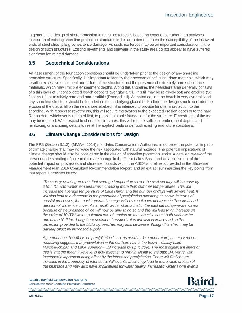
In general, the design of shore protection to resist ice forces is based on experience rather than analyses. Inspection of existing shoreline protection structures in this area demonstrates the susceptibility of the lakeward ends of steel sheet pile groynes to ice damage. As such, ice forces may be an important consideration in the design of such structures. Existing revetments and seawalls in the study area do not appear to have suffered significant ice-related damage.
3.5 Geotechnical Considerations
An assessment of the foundation conditions should be undertaken prior to the design of any shoreline protection structure. Specifically, it is important to identify the presence of soft subsurface materials, which may result in excessive settlement and failure of the structure, and the presence of extremely hard subsurface materials, which may limit pile embedment depths. Along this shoreline, the nearshore area generally consists of a thin layer of unconsolidated beach deposits over glacial till. This till may be relatively soft and erodible (St. Joseph till), or relatively hard and non-erodible (Rannoch till). As noted earlier, the beach is very dynamic and any shoreline structure should be founded on the underlying glacial till. Further, the design should consider the erosion of the glacial till on the nearshore lakebed if it is intended to provide long term protection to the shoreline. With respect to revetments, this will require excavation to the expected erosion depth or to the hard Rannoch till, whichever is reached first, to provide a stable foundation for the structure. Embedment of the toe may be required. With respect to sheet pile structures, this will require sufficient embedment depths and reinforcing or anchoring details to resist the applied loads under both existing and future conditions.
3.6 Climate Change Considerations for Design
The PPS (Section 3.1.3), (MMAH, 2014) mandates Conservations Authorities to consider the potential impacts of climate change that may increase the risk associated with natural hazards. The potential implications of climate change should also be considered in the design of shoreline protection works. A detailed review of the present understanding of potential climate change in the Great Lakes Basin and an assessment of the potential impact on processes and shoreline hazards within the ABCA shoreline is provided in the Shoreline Management Plan 2016 Consultant Recommendation Report, and an extract summarizing the key points from that report is provided below:
“There is general agreement that average temperatures over the next century will increase by 2 to 7 °C, with winter temperatures increasing more than summer temperatures. This will increase the average temperature of Lake Huron and the number of days with severe heat. It will also lead to a decrease in the proportion of precipitation occurring as snow. In terms of coastal processes, the most important change will be a continued decrease in the extent and duration of winter ice cover. As a result, winter storms that in the past did not generate waves because of the presence of ice will now be able to do so and this will lead to an increase on the order of 10‐30% in the potential rate of erosion on the cohesive coast both underwater and of the bluff toe. Longshore sediment transport rates will also increase and so the protection provided to the bluffs by beaches may also decrease, though this effect may be partially offset by increased supply.
Agreement on the effects on precipitation is not as good as for temperature, but most recent modelling suggests that precipitation in the northern half of the basin – mainly Lake Huron/Michigan and Lake Superior – will increase by up to 20%. The most significant effect of this is that the mean lake level is now forecast to remain similar to the past 100 years, with increased evaporation being offset by the increased precipitation. There will likely be an increase in the frequency of intense rainfall events which may lead to more rapid erosion of the bluff face and may also have implications for water quality. Increased winter storm events

Ausable Bayfield Conservation Authority Considerations for Shoreline Protection Structures
12646.101 Page 18
may also lead to more frequent erosion of coastal dunes and the potential for the maximum limit of wave erosion inland to increase.
In summary, climate change impacts on temperature and precipitation have the potential to increase the severity of flooding and dynamic beach hazards and to increase the rate at which bluff recession takes place along the ABCA shoreline and this will require both continued updating of data on coastal processes and bluff recession and caution in assessing the risks to people and property.”
In terms of shore protection design, increased uncertainty in design parameters (wave height, water level and ice), should be considered in design. Monitoring structures is an accepted practice; it is important to be aware of the potential impacts of climate change discussed in this section and their implications for shore protection structures.”
Ausable Bayfield Conservation Authority Considerations for Shoreline Protection Structures
12646.101 Page 19
4. Considerations for Shore Protection
4.1 Introduction
While the overall objective of shore protection is to address the erosion hazard, there are various approaches that may be adopted. The characteristics of the shoreline, the erosion mechanisms and coastal processes are important considerations. The ABCA shoreline includes eroding bluffs with different geological characteristics and recession rates as discussed in Section 2. Some shorelines have beaches at the toe of bluff, that may, or may not protect the nearshore lakebed and bluff from erosion, depending on the size of the beach deposit, and whether it is present during higher water levels. Four general types of shorelines have been identified and are discussed in this section. Considerations for shore protection based on shoreline characteristics and recession rates are discussed in this section. A detailed discussion of shore protection approaches is provided in Section 5.
Shore protection is not permitted on dynamic beaches (PPS, 2014) and dynamic beaches are not discussed in this report. Further information on dynamic beaches is provided in ABCA (2000), MNR (2001) and Aqua Solution 5 et al. (2016). Thus, the discussion that follows is primarily applicable to the eroding bluff shorelines found mostly north of Maple Grove subdivision.
4.2 Severe Shoreline Erosion and Bluff Recession
There are two areas along the ABCA shoreline that experience particularly severe shoreline erosion and bluff recession, the Birchcliff/Melena Heights subdivision and the Lakewood Gardens/Sunny Ridge/Poplar Beach area. The typical characteristics of these areas are as follows:
Top of bluff is receding at an average long-term rate in the order of 0.6 to 1.3 m/yr.
Major slumps occur along the shoreline.
Bluff face has little or no vegetation.
Undercutting of the base of the bluff is typical.
Very little, if any, beach exists at the toe of the bluff.
It is expected that the nearshore lakebed is also eroding and it is the erosion of the nearshore lakebed that controls bluff erosion, as discussed earlier in Section 3.2.
A structure built along this shoreline would have the objective of stabilizing the shoreline at its current location. The nearshore lakebed will continue to erode in front (lakeward) of the structure, resulting in deeper water and exposing the structure to larger waves in the future. In time, this will lead to failure of the structure. If adjacent shorelines are unprotected, the shore protection will be flanked as the shorelines on either side recede. Any narrow beach found at the toe of the eroding bluff will get smaller and eventually disappear as the overall shore profile continues to erode. These processes must be considered in the design of the structure, and will result in a relatively large and costly structure, to address nearshore lakebed downcutting and shoreline retreat, if it is to stabilize the shoreline for a period of more than 5 to 10 years.
It is unlikely that a permanent beach could be developed adjacent to this shoreline without large groyne type structures combined with an offshore sill or breakwater, and a significant quantity of coarse beach fill. This type of protection would be costly, and is suited to protecting long stretches of shoreline, in the order of hundreds of metres or kilometres, and is generally only undertaken by municipalities.

Ausable Bayfield Conservation Authority Considerations for Shoreline Protection Structures
12646.101 Page 20
4.3 Moderate Shoreline Erosion and Bluff Recession
There are many areas along the ABCA shoreline that experience moderate shoreline erosion and bluff recession. The Salvation Army Camp and Vista Beach subdivisions are typical examples. The characteristics of these areas are as follows:
Top of bluff is receding at an average long-term rate in the order of 0.3 to 0.6 m/yr.
Bluff experiences localized slumping.
Bluff contains some vegetation. Typically, a steep unvegetated scarp of up to 3 m high exists at the base of the bluff.
A small beach may exist at the base of the bluff. During storms, particularly at high water levels, the beaches erode, exposing the underlying lakebed and the bluff to erosion.
The nearshore lakebed is eroding close to the shoreline. However, it is likely that in water depths exceeding approximately 2 m, the lakebed will be covered and stabilized by lag deposits of gravel (including cobbles and boulders), indicating the presence of more resistant material (Rannoch till) below this elevation.
Shore protection along these shorelines would have the objective of stabilizing the shoreline at its current location. Erosion of the lakebed and flanking are concerns for shore protection, and relatively substantial structures would be required. Ideally, the base of the structure would extend to the depth of the more resistant Rannoch till, as the nearshore lakebed will continue to erode in front of the structure until it reaches this level. A diminished beach width should be expected.
4.4 Minor Shoreline Erosion and Bluff Recession
The majority of the ABCA shoreline experiences minor shoreline erosion and bluff recession (ABCA, 2000). Pope's Beach, Gammage and Durand-Huronview subdivisions are typical examples. The characteristics of these areas are as follows:
Top of bluff is receding at an average long-term rate in the order of 0.1 to 0.3 m/yr.
Bluff may experience infrequent, localized slumping.
Bluffs are largely vegetated with grasses, shrubs and small trees.
A moderate sized beach exists at the base of the bluff during most water levels. The beach deposit is large enough that it protects the bluff and underlying lakebed from erosion for much of the time.
During high water levels, the beach is eroded, exposing the bluff and nearshore lakebed to erosion. These events may be years or even decades apart, depending on the size of the beach deposit. Erosion of the bluff will be episodic, coinciding with high water levels.
Minor erosion of the nearshore lakebed is occurring close to the shoreline. However, it is likely that in water depths exceeding approximately 1 m, the lakebed will be covered and stabilized by deposits of gravel (including cobbles and boulders), indicating the presence of more resistant material (Rannoch till) below this elevation.
In most cases, the shoreline is unprotected. Structures built along this shoreline would have the objective of preventing erosion during high water levels.
Groynes have been used to enlarge the existing beach, to provide an improved recreational area, and to provide protection from wave runup reaching the bluff during periods of higher water. However, during high water levels, the groynes empty of sand due to wave action, and the shoreline may be exposed to erosion. At some locations, a seawall or revetment has been constructed along the toe of bluff, to provide a second line of

Ausable Bayfield Conservation Authority Considerations for Shoreline Protection Structures
12646.101 Page 21
defense. These structures are often not visible during average or low water levels, when they buried under the beach.
4.5 Stable Shoreline and Bluff
There are some areas of the ABCA shoreline that have not experienced any noticeable erosion of the bluff during the last fifty years. These locations occur where bedrock or Rannoch till exists at the shoreline and across the nearshore area, such as at Dewey Point and Rocky Point, but also in areas such as Houston Heights, Vodden Beach and Ridgeway subdivisions, and where the fillet beach has developed updrift of the breakwaters at Bayfield and Grand Bend. The characteristics of these areas are as follows:
Top of bluff is relatively stable (average long-term erosion rate less than 0.1 m/yr).
Bluff may experience very infrequent slumping as a result of groundwater loading.
Bluffs are well vegetated with mature trees.
A moderate to large sized beach generally exists at the base of the bluff.
The nearshore lakebed is relatively stable. The beach overlies the nearshore lakebed, which consists of either Rannoch till (armoured by lag deposits of gravels, cobbles and boulders) or bedrock.
Updrift of Bayfield and Grand Bend, a substantial beach is retained by the harbour breakwaters. The beach is sufficient to protect the shoreline from erosion during high water levels, though the beach itself may be exposed to erosion.
Structures built along this shoreline would have the objective of preventing wave runup from reaching the base of the bluff, and/or protecting walkways or patio areas built on the base of bluff, particularly during periods of high water levels.
Groynes have been used to enlarge the existing beach to provide an improved recreational area, and to provide protection from wave runup reaching the bluff during periods of high water.
4.6 Summary
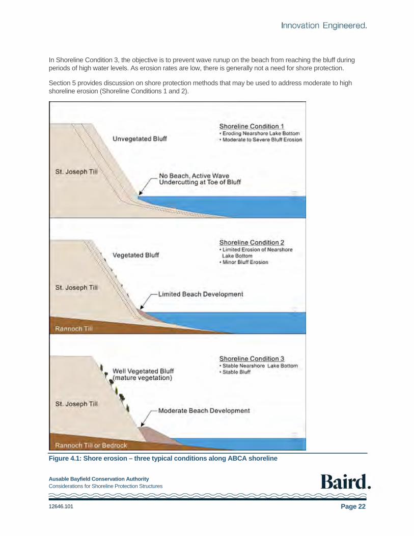
From the perspective of understanding the shoreline erosion mechanism and the different types of shoreline protection structures that may be effective in reducing erosion, it is useful to consider the following three Shoreline Conditions (severe and moderate erosion from the previous discussion can be grouped together):
1. The nearshore lakebed is eroding, and the shoreline and bluff are receding (severe to moderate erosion) as a result of wave action.
2. The nearshore lakebed is eroding, but at a slower rate (minor shoreline erosion), and the shoreline and bluff are receding as a result of wave action.
3. The nearshore lakebed is stable. The shoreline and bluff are also stable (unless adverse landside influences exist).
These three Shoreline Conditions are illustrated schematically in Figure 4.1.
In Shoreline Condition 1, protection of the shoreline will be costly. As erosion of the nearshore lakebed will continue in the future, the design of the structure must have a base embedded at sufficient depth to prevent undermining, and must be designed to resist the larger waves to which it will eventually be exposed. Flanking is a concern where adjacent properties are unprotected.
Similar issues must be considered for Shoreline Condition 2, although the structure will have a longer design life, all things being equal, due to slower erosion of the lakebed.
Ausable Bayfield Conservation Authority Considerations for Shoreline Protection Structures
12646.101 Page 22
In Shoreline Condition 3, the objective is to prevent wave runup on the beach from reaching the bluff during periods of high water levels. As erosion rates are low, there is generally not a need for shore protection.
Section 5 provides discussion on shore protection methods that may be used to address moderate to high shoreline erosion (Shoreline Conditions 1 and 2).
Figure 4.1: Shore erosion – three typical conditions along ABCA shoreline

Ausable Bayfield Conservation Authority Considerations for Shoreline Protection Structures
12646.101 Page 23
5. Structural Shore Protection Approaches
5.1 Introduction
This section presents alternative structural shore protection approaches to address the erosion hazard. Non- structural approaches are preferred, as outlined in the 2000 Shoreline Management Plan and the 2016 Consultant Recommendation Report. Non-structural approaches include observing hazard setbacks as delineated by ABCA, relocation of existing buildings and consolidation of adjacent properties to provide additional area.
While the overall objective of shore protection is to address the erosion hazard, there are various approaches that may be considered. The characteristics of the shoreline, the erosion mechanism and coastal processes are important considerations. The alternatives presented include groynes, seawalls and revetments, which are currently in use along the ABCA shoreline, as well as beach nourishment and offshore breakwaters. Additional information on shore protection design is provided in: The Rock Manual (CIRIA, 2007), EurOtop Manual (2007) and the Coastal Engineering Manual (USACE, 2012).
The selection of a particular approach, including the type of structure and an appropriate design life, is a complicated decision which must consider many factors, including cost (capital and maintenance), performance (protection to the shoreline), aesthetics (principally the structure elevation), access to the water and along the beach if present, and impacts on the nearshore environment and neighbouring shoreline properties. These impacts may extend beyond the adjacent areas and could affect a significant length of downdrift shoreline because of reduced sediment supply to the nearshore system caused by reduced erosion of the backshore. It is important to note that shoreline protection can reduce or eliminate erosion of the backshore, but the long-term erosion of the nearshore lakebed will continue (refer to Section 3.2). Thus, shore protection designs must consider this future deepening of the nearshore, or suffer the consequences, which will ultimately lead to a requirement for costly maintenance, repair, and/or replacement works.
It is emphasized that discussions presented in this report are preliminary in nature. Final designs should be developed on a site-specific basis, within the overall framework of the Shoreline Management Plan (SMP), by a qualified coastal engineer.
5.2 Existing Shore Protection Structures
Various forms of shoreline protection have been constructed along the ABCA shoreline, with the most recent inventory of structures presented in ABCA (1990). The design of individual structures, and the extent of these structures along the shoreline, varies considerably within the jurisdiction of the ABCA. It is recommended that a detailed assessment of current structures be undertaken, and that the 1990 inventory be updated to present day.
There are large, generally unprotected areas (for example, the shoreline between Bayfield Highlands and Birchcliffe), as well as areas with significant protection (for example, the shorelines between Houston Heights North and Homestead Heights, and to the south of Grand Bend Harbour). Groynes and seawalls are the predominant structures, and are generally constructed of steel sheet piling, although gabions, concrete (pre- cast and cast-in-place) and timber have also been used. Rubble mound revetments have also been constructed in some locations, particularly further south along the ABCA shoreline in the region of Armstrong and Southcott Pines. Many of these structures have not been designed by a coastal engineer and many are in a state of disrepair or have failed.

Ausable Bayfield Conservation Authority Considerations for Shoreline Protection Structures
12646.101 Page 24
In general, the existing structures represent efforts to protect the shoreline from storm-related damage, and often have been constructed during or after periods of high water levels. In areas subject to moderate or severe long-term erosion, such as Melena Heights and Poplar Beach, the existing structures will have no significant impact on long term erosion of the shoreline and bluff. This is because the nearshore lakebed continues to erode, as does the adjacent shoreline. Shore protection works will ultimately fail through mechanisms such as undercutting and flanking.
More substantial shore protection has been constructed north of Grand Bend Harbour to protect the Beachplace condominium development (Sandwell Inc.,1990), and to the south of the harbour to protect the Southcott Pines subdivision (Butler & Associates Ltd., 1986). The Beachplace structure, which consists of a rubble mound revetment and a concrete retaining wall, was designed considering an extreme (100-year return period) erosion event on the beach fronting it. The design of the Southcott Pines revetment does not appear to have considered the potential for erosion of the nearshore lakebed in this area, and has since been subjected to settlement and localized failures.
In summary, a variety of shore protection structures exist along the ABCA shoreline, including groynes seawalls and revetments. Most are steel sheet pile structures, though several timber and stone structures have also been constructed. Existing shore protection structures may provide some level of protection at average to low water levels, but many are ineffective at high water levels and will generally not have a significant impact on long term erosion of the shoreline.
5.3 Groynes
5.3.1 Discussion
A groyne is a narrow structure projecting from the shoreline into the nearshore, approximately perpendicular to the shoreline (see Figure 5.1). A groyne system or groyne 'field' is made up of a number of individual groynes, usually of similar length and installed at regular intervals along the shoreline. Groynes come in various shapes (e.g., straight, L-shaped, T-shaped), sizes and materials (e.g., timber, armour stone, concrete blocks or steel sheet piles with pipe piles used as reinforcement).
At shorelines where there is sufficient alongshore transport of beach material, the intent of a groyne is to act as an artificial physical barrier to the natural alongshore drift (beach material) and trap some or all of it on the updrift side of the groyne. The degree of trapping depends on the length of the groyne, i.e., a longer groyne is expected to trap more sediment. Many shorelines have minimal alongshore transport. When this is the case, unless artificially nourished, groynes can only trap the sand that is available, and will not be very effective.
Groynes have been a popular form of shore protection that increase beach stability and size, particularly during lower lake level conditions, at a relatively low cost compared to other alternatives. Straight groynes do little to affect the cross-shore transport and cannot, on their own, provide full protection to the backshore under extreme conditions. As a result, severe beach erosion can still happen during high lake level conditions as well as extreme storm events. Thus, artificial beach nourishment and/or supplementary shore parallel protection (e.g. low crested offshore breakwaters) are typically required in conjunction with straight groynes to provide effective shoreline protection. Alternatively, T-shaped groynes may be used to contain sediment for a longer period compared to straight groynes. Groynes are used in some situations to help anchor beach nourishment.
Trapping of the alongshore transport causes a sediment deficit at the adjacent downdrift properties. The longer the groyne, the larger this deficit. To mitigate the corresponding downdrift impacts, groynes should be prefilled with imported beach material. The prefill volume must also compensate for the bypassing shoal that is formed after construction of the groynes to convey sediment to downdrift shores. Despite these efforts, local erosion of the shoreline immediately downdrift of the groyne may be unavoidable. Groynes can also limit pedestrian

Ausable Bayfield Conservation Authority Considerations for Shoreline Protection Structures
12646.101 Page 25
access along the beach, where there may be a difference in the beach elevation, updrift and downdrift of the groyne. When not properly designed, groynes can also deflect the alongshore material further offshore.
The use of groynes involves the cooperation of many adjacent shoreline property owners. A proper detailed study would only be cost effective for a groyne field which extended across dozens of properties. The design requires a specialized knowledge of coastal processes (i.e., nearshore waves, littoral transport, interaction with structures) and is often completed with the aid of computer models which require a great deal of experience and expertise to be properly utilized. The use of groynes should not be permitted without an express understanding and documentation of the potential adverse impacts to the littoral system, especially at downdrift properties. Increasing shoreline protection will further restrict the already limited supply of littoral material along this shoreline. Groyne design should be accompanied by artificial beach nourishment to compensate for both the trapped sediment and the sediment that will be stored in bypassing shoals. Ongoing nourishment may be required to replenish sediment removed during high water levels and storm events.
Figure 5.1: Plan view of typical groyne field
5.3.2 Application Along ABCA Shoreline
Obtaining permits for the construction of groynes may be challenging or prohibitive. At the time this report was written, ABCA did not permit the construction of new groynes.
5.3.3 Design Features
The design of a groyne system is relatively complex. Detailed design is beyond the scope of this report and will be different from one site to other. The design of a groyne field should be undertaken on a site-specific basis by a qualified coastal engineer. Additional details which may require attention include the potential for flanking of the groynes, the potential for damage to the groynes due to wave forces, ice forces and soil loading conditions, and the potential for downdrift impacts, which may lead to permitting difficulties and mitigation requirements.

Ausable Bayfield Conservation Authority Considerations for Shoreline Protection Structures
12646.101 Page 26
More detailed information on the use of groynes for shore protection is presented in Philpott (1986), CIRIA (1990), CEM (2006). The Philpott reference deals specifically with Great Lakes shorelines, while the CIRIA reference provides an overview of the subject and design guidance for the preparation of detailed designs.
5.4 Revetments
5.4.1 Discussion
Revetments are sloped shore parallel structures with a protective layer of large "armour" stones that are built to prevent the direct attack of waves on the toe of a bluff (see Figure 5.2). These structures rely on the mass of the armour stones to withstand the forces of the waves. As waves impact the structure, energy is dissipated as the water moves over the rough, permeable sloped face of the structure, and through the voids between the armour stones. The land behind the structure is thus protected from the erosional stress that results from wave attack.
Armour stone revetments have advantages over many other forms of shore protection, because they are flexible, can accommodate some settlement and do not generally fail catastrophically. The use of larger armour stones and/or a higher crest elevation will provide a stable structure which protects the backshore under more severe conditions. This type of structure can be designed to accommodate the ongoing erosion of the lakebed, thus providing long term protection to the backshore. However, this will have a significant impact on the capital construction cost, although annual maintenance costs will be reduced.
Revetments, like any other shore protection structure, have a number of disadvantages that make them inappropriate for some conditions. Revetments may severely limit access to the beach and water, and do not increase the amount of recreational space. Beach or water access must often be provided by staircases or ramps located intermittently along the shoreline. Access along the beach may also be obstructed. Another disadvantage of revetments is that the structure does not encourage beach development, and may in fact increase scour in front of the structure as a result of wave reflection at the structure. If the lakebed erodes, higher waves may be able to reach the structure, further eroding the bottom and possibly undermining the structure. Flanking can be an issue at the termination of the structure, particularly if the adjacent property is not protected and is eroding at a high rate.
Armour stone revetments may be relatively expensive compared to other shore protection structures, depending on the exposure of the site, the selected design life of the structure, and the availability of suitable quarried stone material within reasonable proximity to the site. In addition, access to the shoreline for large construction equipment when necessary to place large armour stone, is limited and difficult over much of this area.

Ausable Bayfield Conservation Authority Considerations for Shoreline Protection Structures
12646.101 Page 27
Figure 5.2: Typical armour stone revetment section
5.4.2 Application Along ABCA Shoreline
A revetment structure can be considered to mitigate shoreline recession in areas where the nearshore lakebed is eroding and the shoreline and backshore is subject to moderate to severe erosion. Application of this approach in such areas requires careful consideration of the lakebed erosion, as discussed in the following section. It is important to recognize that a revetment will not provide any recreational benefit to the shoreline, and may in fact reduce access and result in a reduction of existing beach deposits in front of it. In addition, revetments may not be practical along shorelines with high bluffs and limited access, and along shorelines with high erosion rates. These shorelines may be costly to protect, and flanking is a concern when the adjacent shoreline is unprotected. Finally, protecting the shoreline reduces the natural sediment supply to downdrift beaches.
5.4.3 Design Features
The key design features of a revetment are the armour stone size (which must be sufficient to resist the depth limited waves that reach the structure), the crest elevation (which controls the level of runup and overtopping, and thus the potential for damage to the backshore), the toe elevation (which must consider scour of loose sediments in front of the structure as well as the long-term erosion of the nearshore lakebed), the filter layer (which prevents the loss of fine materials behind the revetment through the armour layer), and the end detail to address flanking.
Revetments built along the ABCA shoreline may be constructed with different sizes of armour stone, depending on the wave exposure and design life of the structure, and whether the structure has a single or double layer of armour stone. For example, the revetment structure constructed in the 1990’s along the Southcott Pines subdivision is protected by 3 to 4 tonne armour stones (estimated weight). The design of this structure does not appear to have considered the potential for future erosion of the nearshore lakebed in front of the structure. Recent oblique imagery from 2016 shows damage to the revetment including displacement of armour stone.
The crest elevation of a revetment will greatly affect its performance in high water and/or severe wave conditions. The crest elevation must be designed to limit overtopping by waves. If excessive overtopping occurs, damage to the structure may result as the back of the structure is eroded, or damage to the protected property may result. Wave runup and overtopping levels on a sloping structure may be estimated using a number of approaches, as summarized in EurOtop (2007). If the need for a high crest is established but is not
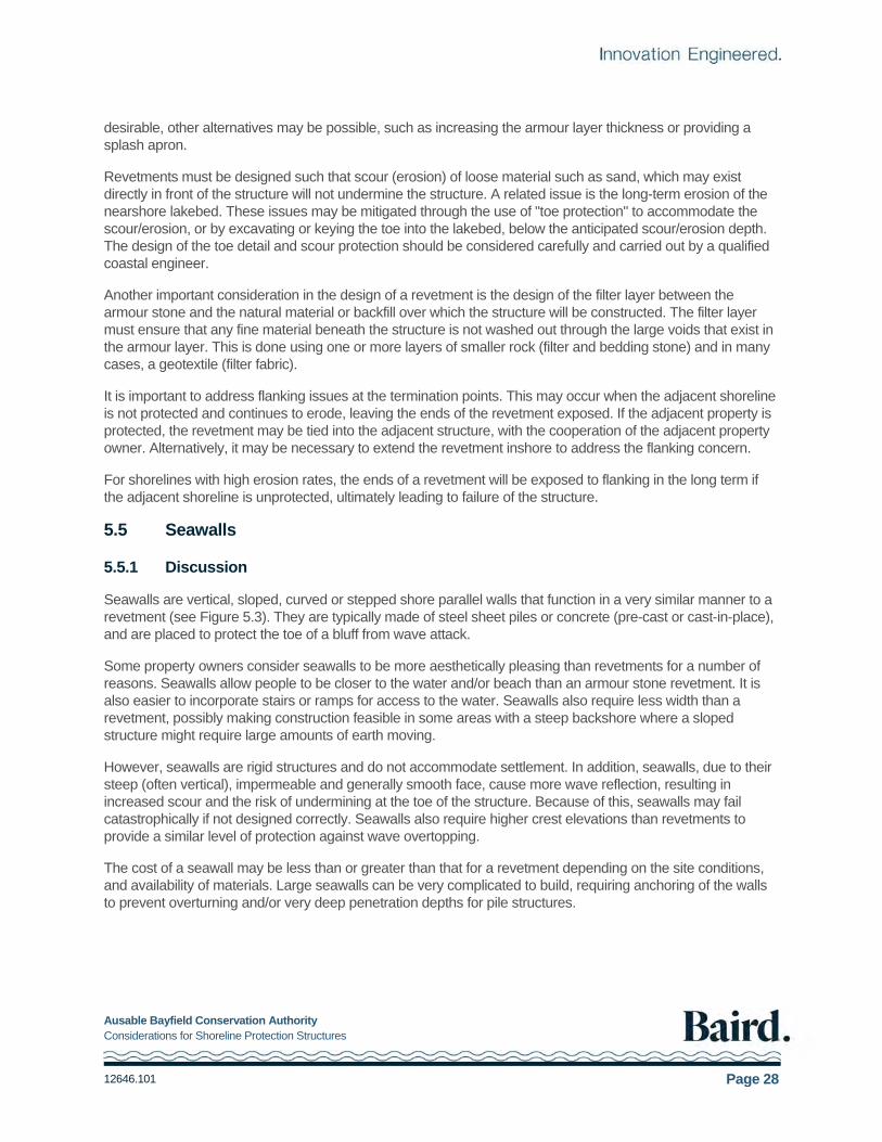
Ausable Bayfield Conservation Authority Considerations for Shoreline Protection Structures
12646.101 Page 28
desirable, other alternatives may be possible, such as increasing the armour layer thickness or providing a splash apron.
Revetments must be designed such that scour (erosion) of loose material such as sand, which may exist directly in front of the structure will not undermine the structure. A related issue is the long-term erosion of the nearshore lakebed. These issues may be mitigated through the use of "toe protection" to accommodate the scour/erosion, or by excavating or keying the toe into the lakebed, below the anticipated scour/erosion depth. The design of the toe detail and scour protection should be considered carefully and carried out by a qualified coastal engineer.
Another important consideration in the design of a revetment is the design of the filter layer between the armour stone and the natural material or backfill over which the structure will be constructed. The filter layer must ensure that any fine material beneath the structure is not washed out through the large voids that exist in the armour layer. This is done using one or more layers of smaller rock (filter and bedding stone) and in many cases, a geotextile (filter fabric).
It is important to address flanking issues at the termination points. This may occur when the adjacent shoreline is not protected and continues to erode, leaving the ends of the revetment exposed. If the adjacent property is protected, the revetment may be tied into the adjacent structure, with the cooperation of the adjacent property owner. Alternatively, it may be necessary to extend the revetment inshore to address the flanking concern.
For shorelines with high erosion rates, the ends of a revetment will be exposed to flanking in the long term if the adjacent shoreline is unprotected, ultimately leading to failure of the structure.
5.5 Seawalls
5.5.1 Discussion
Seawalls are vertical, sloped, curved or stepped shore parallel walls that function in a very similar manner to a revetment (see Figure 5.3). They are typically made of steel sheet piles or concrete (pre-cast or cast-in-place), and are placed to protect the toe of a bluff from wave attack.
Some property owners consider seawalls to be more aesthetically pleasing than revetments for a number of reasons. Seawalls allow people to be closer to the water and/or beach than an armour stone revetment. It is also easier to incorporate stairs or ramps for access to the water. Seawalls also require less width than a revetment, possibly making construction feasible in some areas with a steep backshore where a sloped structure might require large amounts of earth moving.
However, seawalls are rigid structures and do not accommodate settlement. In addition, seawalls, due to their steep (often vertical), impermeable and generally smooth face, cause more wave reflection, resulting in increased scour and the risk of undermining at the toe of the structure. Because of this, seawalls may fail catastrophically if not designed correctly. Seawalls also require higher crest elevations than revetments to provide a similar level of protection against wave overtopping.
The cost of a seawall may be less than or greater than that for a revetment depending on the site conditions, and availability of materials. Large seawalls can be very complicated to build, requiring anchoring of the walls to prevent overturning and/or very deep penetration depths for pile structures.
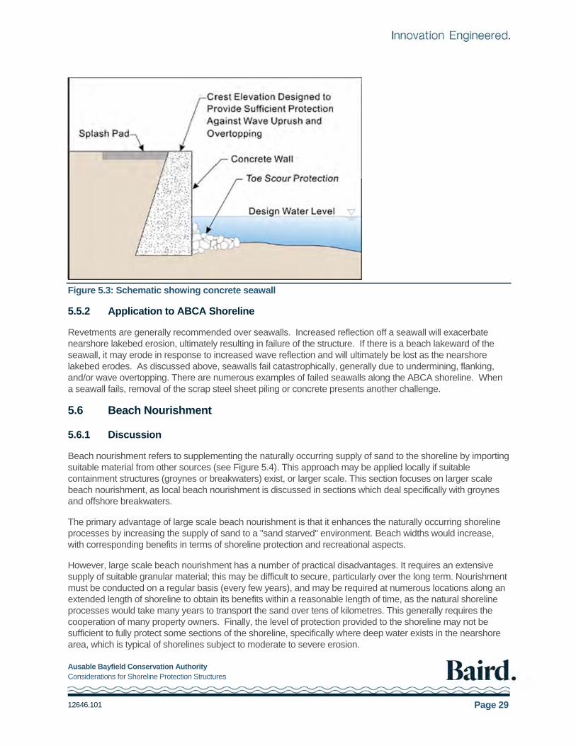
Ausable Bayfield Conservation Authority Considerations for Shoreline Protection Structures
12646.101 Page 29
Figure 5.3: Schematic showing concrete seawall
5.5.2 Application to ABCA Shoreline
Revetments are generally recommended over seawalls. Increased reflection off a seawall will exacerbate nearshore lakebed erosion, ultimately resulting in failure of the structure. If there is a beach lakeward of the seawall, it may erode in response to increased wave reflection and will ultimately be lost as the nearshore lakebed erodes. As discussed above, seawalls fail catastrophically, generally due to undermining, flanking, and/or wave overtopping. There are numerous examples of failed seawalls along the ABCA shoreline. When a seawall fails, removal of the scrap steel sheet piling or concrete presents another challenge.
5.6 Beach Nourishment
5.6.1 Discussion
Beach nourishment refers to supplementing the naturally occurring supply of sand to the shoreline by importing suitable material from other sources (see Figure 5.4). This approach may be applied locally if suitable containment structures (groynes or breakwaters) exist, or larger scale. This section focuses on larger scale beach nourishment, as local beach nourishment is discussed in sections which deal specifically with groynes and offshore breakwaters.
The primary advantage of large scale beach nourishment is that it enhances the naturally occurring shoreline processes by increasing the supply of sand to a "sand starved" environment. Beach widths would increase, with corresponding benefits in terms of shoreline protection and recreational aspects.
However, large scale beach nourishment has a number of practical disadvantages. It requires an extensive supply of suitable granular material; this may be difficult to secure, particularly over the long term. Nourishment must be conducted on a regular basis (every few years), and may be required at numerous locations along an extended length of shoreline to obtain its benefits within a reasonable length of time, as the natural shoreline processes would take many years to transport the sand over tens of kilometres. This generally requires the cooperation of many property owners. Finally, the level of protection provided to the shoreline may not be sufficient to fully protect some sections of the shoreline, specifically where deep water exists in the nearshore area, which is typical of shorelines subject to moderate to severe erosion.

Ausable Bayfield Conservation Authority Considerations for Shoreline Protection Structures
12646.101 Page 30
Figure 5.4: Plan and cross-section showing beach nourishment
5.6.2 Application to ABCA Shoreline
Two approaches have been identified as possibly suitable for large scale beach nourishment along the ABCA shoreline. The first would be to bypass sand across Goderich Harbour. A detailed assessment of sediment processes at Goderich Harbour would be required to undertake sand bypassing. This would restore the supply of sand along the ABCA shoreline to that which naturally occurred prior to the construction of Goderich Harbour in 1916. Bypassing at Goderich could be provided by a permanent sand bypassing system (such as a sand fluidization and pumping process) or by mechanical excavation and transport by barge or truck. If a permanent bypassing system were developed, the sand would be deposited at some distance downdrift of the harbor (to be determined through a sediment transport study and/or monitoring), and it would take many years for the benefits to be achieved along the full ABCA shoreline. If mechanical excavation and transport were adopted, the excavated material could be distributed at selected locations along the shoreline, thus reducing the time required for the benefits to spread along the shoreline.
The second approach for large scale beach nourishment, would be to import suitable granular material (mean grain size diameter (D50 >0.3 mm) from an inland source such as a sand and gravel pit, or perhaps from the extensive dune deposits in the Pinery/Ipperwash area. This latter approach could be considered as a "recycling" program, as material originally deposited in the Pinery/lpperwash "sink" area would be put back into the system at the updrift "source" area. It might be difficult to secure an inland source of suitable material, particularly over the long term, and it seems unlikely that excavation in the Pinery/lpperwash area would be

Ausable Bayfield Conservation Authority Considerations for Shoreline Protection Structures
12646.101 Page 31
permitted. Large projects of this nature require permits from various agencies (ABCA, MNRF, DFO, Ontario Parks), and cooperation between multiple landowner groups, municipalities and conservation authorities.
Clearly, large scale beach nourishment would require the cooperation of the local, provincial and federal governments. Regardless, as discussed elsewhere in Section 5, local beach nourishment should be considered at locations where containment structures (such as groynes and offshore breakwaters) are present or proposed, to provide improved shore protection and recreational beaches, and mitigate adverse impacts.
5.7 Offshore Breakwaters
5.7.1 Discussion
Detached or offshore breakwaters may be used to provide protection to an eroding shoreline. These structures are generally of rubble mound construction, with armour stone placed over a rock filter layer and blasted rock core. They are typically constructed in 2 to 4 m of water. Offshore breakwaters protect the shoreline from direct wave attack (although, depending on the design requirements, they may allow some wave overtopping and transmission through the structure), thus reducing the erosional stress on the shoreline. On shorelines where there is a sufficient supply of alongshore transport, deposition of sand in the lee of the breakwater(s) (the wave "shadow" zone behind the structure) may result in a wider beach in this area. Alternatively, a series of offshore breakwaters may be utilized to contain imported beach fill, thus providing shoreline protection with significant recreational benefits. Both approaches have been utilized on the Great Lakes. A schematic showing beach fill contained by offshore breakwaters is presented in Figure 5.5.
One of the advantages of a series of offshore breakwaters is that they can be designed to protect shorelines which are subject to significant erosion. As the structures are located a certain distance offshore, they will also protect a portion of the nearshore lakebed from further erosion, although their design must consider erosion of the lakebed which may occur lakeward of the breakwater(s). However, the magnitude of lakebed erosion is lower in this area than in the immediate vicinity of the shoreline, so it may be easier to incorporate in the design than for a shoreline revetment. Another advantage of an offshore breakwater system is that it can be used to retain beach fill, thus limiting sand losses from the beach area (both alongshore and offshore) and providing a beach of improved stability.
Offshore breakwater systems have a high cost, require detailed design investigations, and are relatively difficult to construct typically requiring large marine-based equipment. In addition, these structures may result in adverse downdrift impacts due to interference with the natural alongshore transport processes. These impacts can partially be mitigated by pre-filling the beach cells to prevent trapping of sediments that are naturally present and moving along the shoreline.
The use of offshore breakwaters involves the cooperation of many adjacent shoreline property owners. The design requires a specialized knowledge of coastal processes (i.e., nearshore waves, littoral transport, interaction with structures) and is often completed with the aid of computer and physical models which requires a great deal of experience and expertise to be properly utilized. The use of offshore breakwaters should not be permitted without an express understanding and documentation of the potential adverse impacts to the littoral system, especially at downdrift properties. Special attention should be paid in the design to ensure that bypassing of littoral drift towards downdrift beaches will be established following completion of construction. If offshore breakwaters are constructed with too small gaps, the water exchange in the embayments between the breakwaters may be poor. Swimming safety around the structures should also be considered during the design. Boat safety must be considered, particularly for submerged offshore breakwaters, and additional permits may be required (e.g., Navigation Protection Act).
A primary disadvantage of offshore breakwaters is the fact that they normally obstruct at least part of the view over the lake, which means that the visual impact can be unacceptable. Coastal engineers have thus turned to
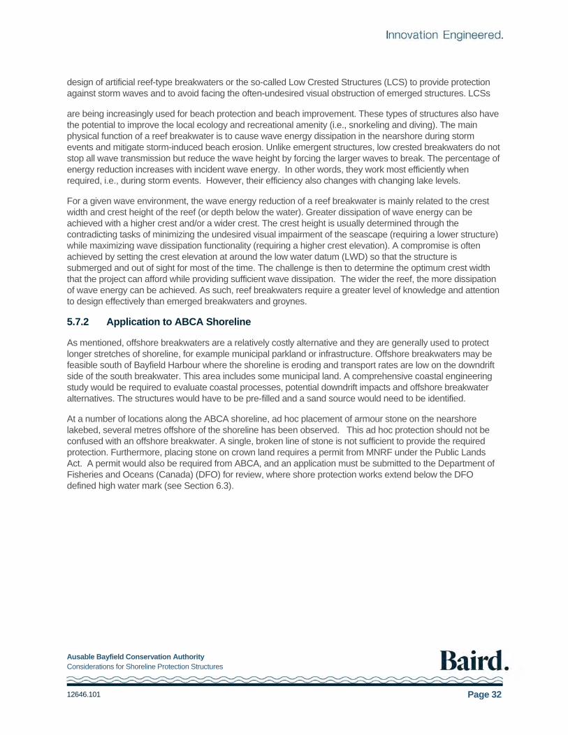
Ausable Bayfield Conservation Authority Considerations for Shoreline Protection Structures
12646.101 Page 32
design of artificial reef-type breakwaters or the so-called Low Crested Structures (LCS) to provide protection against storm waves and to avoid facing the often-undesired visual obstruction of emerged structures. LCSs
are being increasingly used for beach protection and beach improvement. These types of structures also have the potential to improve the local ecology and recreational amenity (i.e., snorkeling and diving). The main physical function of a reef breakwater is to cause wave energy dissipation in the nearshore during storm events and mitigate storm-induced beach erosion. Unlike emergent structures, low crested breakwaters do not stop all wave transmission but reduce the wave height by forcing the larger waves to break. The percentage of energy reduction increases with incident wave energy. In other words, they work most efficiently when required, i.e., during storm events. However, their efficiency also changes with changing lake levels.
For a given wave environment, the wave energy reduction of a reef breakwater is mainly related to the crest width and crest height of the reef (or depth below the water). Greater dissipation of wave energy can be achieved with a higher crest and/or a wider crest. The crest height is usually determined through the contradicting tasks of minimizing the undesired visual impairment of the seascape (requiring a lower structure) while maximizing wave dissipation functionality (requiring a higher crest elevation). A compromise is often achieved by setting the crest elevation at around the low water datum (LWD) so that the structure is submerged and out of sight for most of the time. The challenge is then to determine the optimum crest width that the project can afford while providing sufficient wave dissipation. The wider the reef, the more dissipation of wave energy can be achieved. As such, reef breakwaters require a greater level of knowledge and attention to design effectively than emerged breakwaters and groynes.
5.7.2 Application to ABCA Shoreline
As mentioned, offshore breakwaters are a relatively costly alternative and they are generally used to protect longer stretches of shoreline, for example municipal parkland or infrastructure. Offshore breakwaters may be feasible south of Bayfield Harbour where the shoreline is eroding and transport rates are low on the downdrift side of the south breakwater. This area includes some municipal land. A comprehensive coastal engineering study would be required to evaluate coastal processes, potential downdrift impacts and offshore breakwater alternatives. The structures would have to be pre-filled and a sand source would need to be identified.
At a number of locations along the ABCA shoreline, ad hoc placement of armour stone on the nearshore lakebed, several metres offshore of the shoreline has been observed. This ad hoc protection should not be confused with an offshore breakwater. A single, broken line of stone is not sufficient to provide the required protection. Furthermore, placing stone on crown land requires a permit from MNRF under the Public Lands Act. A permit would also be required from ABCA, and an application must be submitted to the Department of Fisheries and Oceans (Canada) (DFO) for review, where shore protection works extend below the DFO defined high water mark (see Section 6.3).
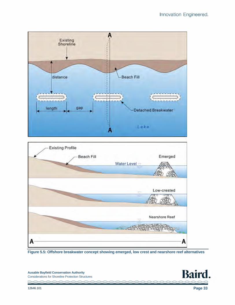
Ausable Bayfield Conservation Authority Considerations for Shoreline Protection Structures
12646.101 Page 33
Figure 5.5: Offshore breakwater concept showing emerged, low crest and nearshore reef alternatives

Ausable Bayfield Conservation Authority Considerations for Shoreline Protection Structures
12646.101 Page 34
6. Implementation
Previous sections of this report provided discussion on shoreline issues and the related objectives of shore protection, as well as design considerations and criteria, and alternative methods of shore protection for the ABCA shoreline. This section discusses the various steps and considerations for the implementation of a shore protection project along the ABCA shoreline.
6.1 Shoreline Management Plan and Considerations for Shore Protection
The ABCA Shoreline Management Plan 2000 provides direction regarding shoreline management planning along the ABCA shoreline. Where shoreline erosion is an issue, non- structural approaches to address the erosion hazard are preferred, and should be considered prior to structural protection. Non-structural approaches include, observing hazard setbacks as delineated by ABCA, relocation of existing buildings; and consolidation of adjacent properties to provide additional area.
Shoreline management planning globally and in Ontario continues to evolve. The PPS (MMAH, 2014) delegates responsibility for providing input with respect to Natural Hazards to the Conservation Authorities. It requires the Authority to ensure that no new hazards are created; existing hazards are not aggravated; and adverse environmental impacts do not result. The ABCA Shoreline Management Plan 2000 is under review and policies for permitting shore protection works will be updated in the future.
6.2 Ownership
Prior to initiating design of the shore protection works, it is important to establish the ownership of the land on which the structure is to be built. The owner should not assume, without supporting evidence, that the lot extends to the waterline or into the lake. The legal definition of the lakeward limit of waterfront lots varies within the jurisdiction of the ABCA. There are examples along the ABCA shoreline where lots extend to a defined line landward of the top of the bluff, to the top of the bluff, to the waterline, or to a defined line lakeward of the toe of the bluff.
Prior to any design effort, the property owner should obtain a copy of the registered survey/deed for the property. If the lot limits are unclear, this matter should be discussed with a lawyer experienced with lakefront ownership issues.
6.3 Permits and Approvals
Permits and approvals are required for the construction of shore protection works. The permitting requirements are outlined in this section. It is recommended that the proponent contact the agencies early in the design process, to obtain input regarding the agency policies and acceptable practices.
Under Ontario Regulation 147/06, Regulation of Development, Interference with Wetlands and Alterations to Shorelines and Watercourses, a permit is required from ABCA for development within the hazard lands including the construction of shore protection works. The following information may be required (additional information is provided in Appendix D):
site location
site description, including environmentally significant features
description of the need for and details of the proposed works
engineering drawings including plan and sections

Ausable Bayfield Conservation Authority Considerations for Shoreline Protection Structures
12646.101 Page 35
specifications including materials to be used
coastal conditions, design parameters, and sand transport
construction schedule
access and maintenance requirement
a coastal engineering report may be required to demonstrate that development is carried out in accordance with protection works standards and access standards
a coastal engineering report may be required to demonstrate that new hazards are not created and existing hazards are not aggravated
a coastal engineering report may be required to demonstrate the proposed works will not adversely affect sediment transport and will have no adverse impacts on adjacent properties
demonstrate that no adverse environmental impacts will result
monitoring program
A Work Permit is required from the Ministry of Natural Resources and Forestry under the Public Lands Act, which provides for the management, sale and disposition of public lands, including the beds of most lakes and rivers. Construction on Crown Land requires the approval of MNRF. The MNRF may specify conditions including requirements for siltation control devices and timing windows for in-water work to protect fisheries.
The Fisheries Act prohibits the carrying on of a work, undertaking or activity that results in serious harm to fish that are part of or support a commercial recreational or Aboriginal fishery. Serious harm to fish is defined as: the death of fish or the permanent alteration to, or destruction of, fish habitat, with fish habitat defined as spawning grounds and any other areas, including nursery, rearing, food supply and migration areas, on which fish depend directly or indirectly to carry out their life processes. The Department of Fisheries and Oceans (Canada) (DFO) is responsible for implementation of the Act. Where shore protection works extend below the DFO defined high water mark, an application must be submitted to DFO for review. This process may be initiated by an on- line self-assessment. DFO will determine if formal approval is not required and may specify restrictions on the work.
The Species at Risk Act (SARA) was enacted to prevent wildlife species in Canada from disappearing, and to provide for the recovery of wildlife species that no longer exist in the wild, are endangered, or threatened as a result of human activity, and to manage species of special concern from becoming endangered or threatened. Project review by qualified personnel is required to ensure any species at risk are identified and the requirements of the SARA are addressed.
The Navigation Protection Act (NPA) is a federal statute designed to protect the public right of navigation in navigable waters by prohibiting the building or placement of any work without the approval of the Transport Canada. The Act was amended in 2012 and Lake Huron is included in the List of Scheduled Waters and is therefore included under the Act. Construction of works that may interfere with navigation would require a permit under the NPA.
6.4 Community Approach
A coordinated approach to shoreline protection by a community or subdivision, as opposed to an individual property by property approach, has a number of important advantages. Works planned and constructed along an extended section of shoreline will provide more effective protection than shorter individual works. In addition, overall construction (and design) costs are reduced through a coordinated approach, and maintenance work will be easier to undertake and less expensive than for a series of isolated projects. It may also prove beneficial during the permit and approval phase. For these reasons, a community approach to shoreline protection is recommended where possible along the ABCA shoreline.

Ausable Bayfield Conservation Authority Considerations for Shoreline Protection Structures
12646.101 Page 36
6.5 Preparation of a Final Design
The design of shore protection structures should be prepared by a licensed Professional Engineer with experience and qualifications in coastal engineering. The shore protection designs should be compatible with the ABCA Shoreline Management Plan.
The development of specific designs will, typically, include the following activities:
1. Meeting with Professional Engineer
The property owner meets with the Engineer to discuss the project objectives, site conditions, historical changes, preferred shore protection alternatives, budget and timing. At this meeting, the Engineer may also collect any existing data such as topographic surveys of the property, nearshore bathymetric surveys, geotechnical data, and any other relevant information.
2. Site Visit and Data Collection
A site visit is required and may be undertaken at the same time as the initial meeting. The Engineer may review: characteristics of the bluff, characteristics of the shoreline, depth of sand in the beach, type of material underneath the beach (till, gravel, bedrock), offshore extent of beach, characteristics of lakebed.
Data collection may include: photographs, topographic and bathymetric surveys or depth measurements and geotechnical investigations.
3. Analyses and Conceptual Design
Engineering analyses will be undertaken to develop the shore protection design. This may include:
estimate historical downcutting of nearshore lakebed (refer to Section 3.2 of this report),
establish design conditions for water levels and waves (refer to Sections 3.1 and 3.3 respectively),
prepare conceptual designs (refer to Section 5.0 of this report),
assessment of impacts on coastal processes and adjacent shoreline,
assessment of bluff slope stability analysis, and drainage issues,
develop conceptual design drawings and opinion of probable cost,
discussion and confirmation of conceptual designs by Owner.
4. Final Design and Tender Documents
This will generally include development of final design drawings and technical specifications, consideration of materials sourcing, cost of materials, access to the site, construction methodology, impacts on shoreline and coastal processes.
5. Permit Applications
The Engineer can assist with this process, including preparation and submission of applications, and response to questions from the permitting agencies.
6. Tendering Process
The Engineer can assist with the tender process, identifying suitable contractors, responding to questions during bidding, reviewing the bids and preparing an agreement.

Ausable Bayfield Conservation Authority Considerations for Shoreline Protection Structures
12646.101 Page 37
7. Construction Observation
It is recommended that an experienced Engineer be on site during construction. This may be full time or intermittent. It is generally recommended that the designer is on site during construction.
8. Monitoring
The performance and condition of the shore protection should be monitored at regular intervals and after storm events.
6.6 Construction
Although construction can, in some cases, be undertaken by the landowner, in general it should be completed by a contractor with experience in shoreline construction. Landowners would be well-advised to meet and discuss the project with several qualified contractors, and to obtain written quotes based on the final designs, plans and specifications for the work. Prior to selecting a contractor, it would also be beneficial to examine past performance on similar projects, identified by a list of references provided by the contractor. Based on this information, the landowner can make an informed selection of the best contractor for the job. It is advisable that a formal, signed agreement be completed with the contractor prior to commencing the work.
Depending on the nature and magnitude of the project, it may also be advisable to provide on-site observation and project management during construction. This might involve part or full-time observation by a qualified coastal engineer, preferably the project designer. Quality control during construction is an essential component of a successful project, and should not be overlooked. Construction which does not meet the project specifications may not achieve the level of performance intended by the original design, and could result in costly damage and maintenance /repair requirements.
6.7 Monitoring and Maintenance
Due to the harsh environment, structures along the shoreline are subject to damage and wear and tear. Some level of damage should be expected. Therefore, an essential component of any shoreline protection project is an on-going monitoring and maintenance program. It is a requirement of permitting to provide access for maintenance, when any new shore protection is constructed.
A visual inspection of structures should be completed by a qualified individual on an annual basis, and following severe storms, to identify potential problems before excessive and irreparable damage occurs. To maintain the performance of the structure according to its original design intent, maintenance and repairs should be undertaken as soon as possible after a potential problem area is identified.
It is also recommended that property owners monitor the bluff and shoreline on a regular basis. The resulting information will be of great value when a structure is to be designed. Surveys may consist of measurements of the top of the bluff, bottom of the bluff and beach relative to fixed features. A photographic record with photographs taken from a similar position and including fixed features in the field of view would also be useful. Surveys and photographs should be taken on a regular basis, possibly in the spring and fall of each year and following severe storms.

Ausable Bayfield Conservation Authority Considerations for Shoreline Protection Structures
12646.101 Page 38
7. Recommendations
Recommendations addressing shore protection along the ABCA shoreline have been developed. One objective of these recommendations was to balance the desire to maintain, and enhance if possible, the existing sand beaches along the shoreline with the increasing pressure for shoreline protection. Maintaining the sand beaches requires allowing the continued source of sand from eroding bluffs, the longshore transport of sand to the south, and the deposition of sand in the Grand Bend/Pinery/lpperwash beach system. A second objective was to develop recommendations with respect to the selection, design and implementation of shore protection structures along the ABCA shoreline. These recommendations are summarized below. The recommendations address structural protection that is intended to stabilize the shoreline in areas that are eroding. The recommendations do not address non-structural protection such as slope drainage measures and vegetating the slope.
7.1 Prevention versus Protection
Wherever possible along the ABCA shoreline, the use of development setbacks, the relocation of existing buildings, and the acquisition of shoreline property by public organizations (i.e., the townships, municipalities and ABCA) should be utilized rather than the construction of shore protection structures. For new development, the application of this concept is relatively simple, and requires that no new development be constructed within the 100-year erosion hazard limit, including stable slope and erosion allowances. For existing development, the application of this concept is more complicated (refer to SMP Section 3.3 - Policy).
Eliminating shore protection structures allows the bluffs to continue to erode naturally and provide sand to the shoreline for the beaches.
The PPS (2014) directs the ABCA to ensure that no new hazards are created; existing hazards are not aggravated; and adverse environmental impacts do not result. Construction of shore protection invariably has impacts, including a reduction in the supply of sediment to downdrift shorelines. The ABCA SMP is under review and policies regarding shore protection will be updated in the future.
7.2 Protection Alternatives
From a theoretical perspective, regional beach nourishment would be a desirable protection alternative with respect to maintaining/enhancing coastal processes. However, from a practical perspective, it is unlikely that a regional beach nourishment scheme could be implemented in the foreseeable future. A nourishment scheme would involve placing a significant quantity of sand on the shoreline each year.
In areas subject to moderate to severe long-term erosion (average recession rate greater than 0.3 m/yr), an engineered rubble mound revetment can be designed to provide protection. However, it is costly and in the long term, erosion of the nearshore lakebed will continue. If adjacent properties are not protected, the shorelines on either side will continue to erode and flanking of the structure is a common failure mechanism. The design of any revetment should be done by a professional engineer and must consider the downcutting of the lakebed and flanking. Generally, groynes will not provide adequate protection in areas subject to moderate to severe long-term erosion.
In areas subject to minor long-term erosion (average recession rate less than 0.3 m/yr), revetments are an effective means of shore protection. While groynes can be used to enhance the beach at some locations, they will not provide full protection to the shoreline during extreme conditions such as severe storms at high water levels. As noted previously, obtaining permits for groynes may be challenging. If permitted, groynes must be

Ausable Bayfield Conservation Authority Considerations for Shoreline Protection Structures
12646.101 Page 39
prefilled with suitable beach fill (clean sand and gravel, D50 > 0.3 mm) to reduce downdrift impacts. All impacts must be identified and addressed.
Offshore breakwaters containing imported beach fill may be considered by the Village of Bayfield for the area to the south of the harbour. This type of approach is relatively expensive, but can provide significant recreational benefits as well as effective erosion protection. The potential impacts of such a project located immediately south of Bayfield Harbour would be limited due to the presence of the harbour structures. A detailed coastal study would be required to assess the feasibility.
Reflective seawalls, such as steel sheet pile walls, are not recommended for erosion protection anywhere along the ABCA shoreline. Seawalls, due to their steep, impermeable and generally smooth face, cause more wave reflection, resulting in increased scour and the risk of undermining at the toe of the structure. Because of this, seawalls may fail catastrophically if not designed correctly. Seawalls also require higher crest elevations than revetments to provide a similar level of protection against wave overtopping.
7.3 Implementation
Shore protection must be consistent with the ABCA Shoreline Management Plan, which is currently under review.
Prior to design, the ownership of the land on which the structure is to be built should be clearly established, including lakebed if the shore protection extends onto the lakebed.
The design of structures located above the 100-year flood level that are intended to provide protection from wave runup and storm damage should follow guidance presented in MNR (1986) and/or USACOE (1978, 1981).
The design of structures which extend below the 100-year flood level and/or that are intended to stabilize the shoreline against continuing erosion should be done by a professional engineer with experience and qualifications in coastal engineering.
Permit applications must be submitted to all relevant agencies.
Applications to construct shore protection structures must be accompanied by a detailed description of the site and proposed work, including drawings, specifications and a coastal assessment demonstrating the project will not adversely impact the environment and that new hazards are not created, and existing hazards are not aggravated.
A co-ordinated approach (by community or subdivision) is recommended where appropriate.
Quality control during construction is an essential component of a successful project, and suitable construction observation services should be provided.
Monitoring of completed projects should be completed annually, and following severe storms, such that potential problems can be identified before excessive and unrepairable damage occurs.
7.4 Future Work
This section provides recommendations for additional studies to support ABCA shoreline management planning.
1. It is recommended that ABCA update policies and procedures for dealing with shore protection along the ABCA shoreline, to reflect the PPS (MMAH, 2014) and direction in the Technical Guide (MNR, 2001). This would include updating the information required to accompany applications for shore protection, to ensure that the ecosystem and coastal processes are not impacted and that negative impacts on other shoreline properties are not created. In addition, shore protection should be designed by a licensed Professional Engineer with experience and qualifications in coastal engineering.

Ausable Bayfield Conservation Authority Considerations for Shoreline Protection Structures
12646.101 Page 40
2. The ABCA (1990) Inventory of Erosion Control Structures on Lake Huron should be updated with future changes tracked based on permits issued. It is almost 30 years since the previous work was done and conditions have changed. This would provide important data for shoreline management planning and updates to the sediment budget.
3. It is recommended that the sediment budget (Reinders, 1989), be updated to provide improved understanding of the impacts of shore protection on downdrift beaches. This would follow the updated structures inventory and should reflect updated shoreline erosion rates and an assessment of bypassing at Goderich, Bayfield and Grand Bend. It should also include an assessment of long term beach stability at the Pinery and Ipperwash.
4. The annual oblique aerial photography collected by ABCA is beneficial to shoreline management planning and should continue.

Ausable Bayfield Conservation Authority Considerations for Shoreline Protection Structures
12646.101 Page 41
8. References
Ausable-Bayfield Conservation Authority (ABCA). (1990). “Inventory of Erosion Control Structures on Lake Huron”. October 1990.
Ausable-Bayfield Conservation Authority (ABCA). (1994). “Shoreline Management Plan”.
Ausable-Bayfield Conservation Authority (ABCA). (2000). Shoreline Management Plan, Second Edition.
Atria Engineering Hydraulics Inc. (1991). “Wave Uprush - Great Lakes and St. Lawrence River Shorelines: Guidelines for Acceptable Practice”. Report prepared for Conservation Authorities and Water Management Branch, Ontario MNR, March 1991.
Baird & Associates. (2005). Regime Change (Man Made Intervention) and Ongoing Erosion in the St. Clair
River and Impacts on Lake Michigan-Huron Lake Levels. A report prepared for the GBA Foundation.
Baird & Associates (2015). “Highland Park Lakefront Interceptor – Concept Design Report”. Technical Report. January 2015.
Brown, E.A., Wu, C.H., Mickelson, D.M., and Edil, T.B. (2005). “Factors Controlling Rates of Bluff Recession
at Two Sites on Lake Michigan”. Journal of Great Lakes Research, 31, 306-321.
Butler & Associates (1985) Ltd., "Shoreline Erosion Control Programme". Report prepared for Southcott Pines Rate Payers Association, June 1986.
Carter, C.H. and Guy, D.R. Jr. (1988). Coastal Erosion: Processes, Timing and Magnitudes at the Bluff Toe.
Marine Geology, 84, 1-17, 1988.
CIRIA (Construction Industry Research and Information Association). (1990). "Guide on the Use of Groynes in Coastal Engineering". Report RP119, 1990.
CIRIA (Construction Industry Research and Information Association), “The Rock Manual – The Use of Rock
in Hydraulic Engineering” 2nd Edition, London, 2007.
Davidson-Arnott R.G.D. (1986). "Erosion of the Nearshore Profile In Till: Rates, Controls and Implications for Shoreline Protection". Proceedings of Symposium on Cohesive Shores, Burlington, Ontario NRC ACROSES, May 1986.
Davidson-Arnott, R.G.D. (1986). “Rates of Erosion of Till in the Nearshore Zone”. Earth Surface Processes
and Landforms 11”. 53-58, 1986.
Davidson-Arnott, R.G.D. (2010). “Introduction to Coastal Processes and Geomorphology”. Cambridge University Press, Cambridge, England. 442 pp.
Davidson-Arnott, R.G.D. (2016). “Erosion of Cohesive Bluff Shorelines. A Discussion Paper on Processes
Controlling Erosion and Recession of Cohesive Shorelines with Particular Reference to the ABCA Shoreline North of Grand Bend”. University of Guelph, July 2016.
Edil, T.B. and Vallejo, L.E. (1980). “Mechanisms of Coastal Landslides and the Influence of Slope
Parameters”. Engineering Geology, 16, 83-96. Carter and Guy, 1988.
Environment Canada, Inland Waters Directorate, Water Resources Branch. (1988). "Historical Water Levels

Ausable Bayfield Conservation Authority Considerations for Shoreline Protection Structures
12646.101 Page 42
Summary, Ontario, to 1987".
Environment Canada, Inland Waters Directorate. (1991). "Monthly Water Level Bulletin - Great Lakes and Montreal Harbour". September 1991.
EurOtop Manual. (2007). “Overtopping Manual; Wave Overtopping of Sea Defences and Related Structures
– Assessment Manual”. UK: N.W.H. Allsop, T. Pullen, T. Bruce. NL: J.W. van der Meer. DE: H. Schuttrumpf, A. Kortenhaus. www.overtopping-manual.com.
F.J. Reinders & Associates. (1989). "Lake Huron Shoreline Processes Study". Report prepared for ABCA,
MVCA, SCRCA and SVCA, December 1989.
Goda, Y. (1970). "A Synthesis of Breaker Indices". Transactions of the Japanese Society of Civil Engineers. Vol. 2, Part 2, pp 227-230.
Goda, Y. (1975). "Irregular Wave Deformation in the Surf Zone". Coastal Engineering Japan, Vol.18, pp 13-
26. Goda, Y. (1985). “Random Seas and Design of Maritime Structures”. University of Tokyo Press.
Golder Associates. (1972). "Preliminary Study and Evaluation - Lake Huron Erosion". Report prepared for Southcott Pines Ltd., December 1972.
Great Lakes Environmental Research Laboratory. (1987). "Great Lakes Storm Surge Planning Program
(SSPP)". NOAA Technical Memorandum ERL GLERL-65, August 1987.
Great Lakes Basin Commission. "The Role of Vegetation in Shoreline Management". Undated.
Hubertz, J. (1989). "A Wind-Wave Hindcast for the Great Lakes, 1956-87". Proceedings of 2nd International Workshop on Wave Hindcasting and Forecasting, Vancouver, B.C., April 1989.
International Joint Commission. (2009). Upper Great Lakes Study. Impacts on Upper Great Lakes Water
Levels: St. Clair River. Final report to the International Joint Commission, December 2009. Kamphuis, J.W. (1990). "Improving Shore Protection Design". Canadian Journal of Civil Engineering Vol. 17,
No.2. pp. 142-147, April 1990.
Ministry of Municipal Affairs and Housing (MMAH). (2014). The Provincial Policy Statement. Under the Planning Act.
Ministry of Natural Resources (MNR). (1988). "How to Protect Your Shore Property".
Ministry of Natural Resources (MNR). (1988). "Wave Climate Database Catalogue". May 1988. Ministry of
Natural Resources (MNR). (1989). "Great Lakes Flood Levels and Water Related Hazards". February 1989.
Ministry of Natural Resources (MNR). (1989). "Great Lakes System-Flood Levels and Water Related
Hazards", February 1989.
Ministry of Natural Resources (MNR). (1990). "Great Lakes - St. Lawrence River, Flood and Erosion Policy Statement - Draft". September 1990.
Ministry of Natural Resources (MNR). (2001). "Great Lakes - St. Lawrence River System Technical Guide for
Flooding, Erosion and Dynamic Beaches.

Ausable Bayfield Conservation Authority Considerations for Shoreline Protection Structures
12646.101 Page 43
Nairn, R.B. and Baird & Associates. (1992). “Erosion Processes Evaluation Paper”. Final report prepared for the International Joint Commission, June 1992.
Nairn, R.B. and Southgate, H.N. (1993). “Deterministic Profile Modelling of Nearshore Processes, Part
2. Sediment Transport and Beach Profile Development”. Coastal Engineering, 19, 57-96.
Peever, D. (1991). Personal Communication.
Philpott Consulting Ltd. (1986). "Guidelines for Groyne Installations in the Great Lakes”. Report prepared for MNR, November 1986.
Reinders, F.J. and Associates. (1989). “Lake Huron Shore Processes Study”, report prepared for ABCA, MVCA, SCRCA and SVCA.
Sandwell Inc. (1990). "Report on Coastal Processes and the Impact of the Beachplace Development/Trillium Beach Estates Development on the Beach at Grand Bend". Report prepared for Chatham District MNR, March 1990.
U.S. Army Corps of Engineers Waterways Experiment Station. (1977). “Shore Protection Manual, Third
Edition”.
U.S. Army Corps of Engineers North Central Division. (1978). "Help Yourself', September 1978.
U.S. Army Corps of Engineers. (1981). "Low Cost Shore Protection".
U.S. Army Corps of Engineers Waterways Experiment Station (1984). “Shore Protection Manual, Fourth Edition”.
U.S. Army Corps of Engineers. (1988). "Revised Report on Great Lakes Open-Coast Flood Levels". Report
prepared for the Federal Emergency Management Agency, February 1988.
U.S. Army Corps of Engineers. (1991). “ACES (Automated Coastal Engineering System), Version 1.05”. April 1991.
U.S. Army Corps of Engineers. (2002). “Coastal Engineering Manual (CEM)”. U.S. Army Corps of Engineers,
Washington, D.C. (6 Volumes)
U.S. Army Corps of Engineers. (2006). “Coastal Engineering Manual (CEM)”. U.S. Army Corps of Engineers, Washington, D.C. (6 Volumes)
U.S. Army Corps of Engineers, (2010). “WIS (Wave Information Studies)”. Coastal and Hydraulics
Laboratory Engineer Research and Development Center, December 2010.
U.S. Army Corps of Engineers. (2012). “Coastal Engineering Manual (CEM)”. U.S. Army Corps of Engineers, Washington, D.C. (6 Volumes)

Ausable Bayfield Conservation Authority Considerations for Shoreline Protection Structures
12646.101 Appendix A
Shoreline Reaches from Goderich to Kettle Point (from
Reinders, 1989)

Ausable Bayfield Conservation Authority Considerations for Shoreline Protection Structures
12646.101 Appendix A
Reach G. Goderich (Maitland River) to Goderich Water Treatment Plant
Length 1.7 km
Description
Nearshore Bedrock controls wave action at the shoreline.
Shoreline Sand beach at the north in the lee of the harbour structures. A sand/cobble beach has been built at Christopher Beach using dredge spoil. The shoreline has been protected at the water treatment plant.
Bluff Bluffs are now protected and slope stability is the principal consideration.
Recession rate is 0.00 m/year.
Source of Sand
Bluff None
Lakebed 1,030 cubic metres/year
Creeks & Rivers None
Gullies None
Sand Losses None
Sand Transport Minor due to control imposed by man-made structure.
Structures and Shore Protection
Shoreline completely protected.
Shoreline Management – Recommendations
Study to be undertaken of feasibility of nourishing the shoreline with volume of sand equivalent to that supplied to the shoreline if the bluffs were allowed to erode.
Study bypassing sand from north side of harbour past this reach (see notes for previous reach).
Reference Bishop (1987), Boyd et al (1986), Etmanski and Scroth (1979), Etmanski and Scroth (19890), Golder Associates (1979), Golder Associates (1984), MacLaren (1979), Reinders (1984).
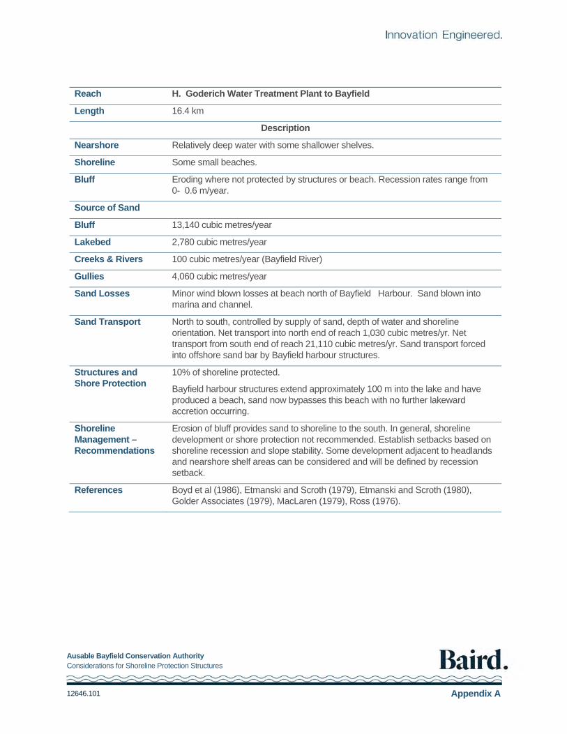
Ausable Bayfield Conservation Authority Considerations for Shoreline Protection Structures
12646.101 Appendix A
Reach H. Goderich Water Treatment Plant to Bayfield
Length 16.4 km
Description
Nearshore Relatively deep water with some shallower shelves.
Shoreline Some small beaches.
Bluff Eroding where not protected by structures or beach. Recession rates range from 0- 0.6 m/year.
Source of Sand
Bluff 13,140 cubic metres/year
Lakebed 2,780 cubic metres/year
Creeks & Rivers 100 cubic metres/year (Bayfield River)
Gullies 4,060 cubic metres/year
Sand Losses Minor wind blown losses at beach north of Bayfield Harbour. Sand blown into marina and channel.
Sand Transport North to south, controlled by supply of sand, depth of water and shoreline orientation. Net transport into north end of reach 1,030 cubic metres/yr. Net transport from south end of reach 21,110 cubic metres/yr. Sand transport forced into offshore sand bar by Bayfield harbour structures.
Structures and Shore Protection
10% of shoreline protected.
Bayfield harbour structures extend approximately 100 m into the lake and have produced a beach, sand now bypasses this beach with no further lakeward accretion occurring.
Shoreline Management – Recommendations
Erosion of bluff provides sand to shoreline to the south. In general, shoreline development or shore protection not recommended. Establish setbacks based on shoreline recession and slope stability. Some development adjacent to headlands and nearshore shelf areas can be considered and will be defined by recession setback.
References Boyd et al (1986), Etmanski and Scroth (1979), Etmanski and Scroth (1980), Golder Associates (1979), MacLaren (1979), Ross (1976).

Ausable Bayfield Conservation Authority Considerations for Shoreline Protection Structures
12646.101 Appendix A
Reach I Bayfield to Highway #83
Length 27 km
Description
Nearshore Relatively deep water with some shallower shelves.
Shoreline Small, frequently persistent beaches, depending on depth of water.
Bluff Eroding when not protected by structures or beach. Recession rates range from O - 0.7 m/year.
Source of Sand
Bluff 32,570 cubic metres/year.
Lakebed 7,410 cubic metres/year
Creeks & Rivers 420 cubic metres/year
Gullies 4,210 cubic metres/year
Sand Losses Minor
Sand Transport North to south, controlled by supply of sand, depth of water and shoreline orientation. Net transport into north end of reach, 21,110 cubic metres/yr. Net transport from south end of reach 65,714 cubic metres/yr.
Structures and Shore Protection
22% of shoreline protected. Approximately half of groynes within this reach are short groynes (short groynes do not extend significantly past the end of the beach). Bayfield harbour structures have detrimental effect on shoreline immediately to the south. Sand is forced to the offshore sand bar before returning to the shoreline.
Shoreline Management – Recommendations
Erosion of bluffs provides sand to shoreline to the south. Shoreline development or protection not recommended. Establish setbacks based on recession.
Consider shore protection south of Bayfield structures where sand transport has been forced offshore.
References Quigley et al., (1974)

Ausable Bayfield Conservation Authority Considerations for Shoreline Protection Structures
12646.101 Appendix A
Reach J. Highway #83 to Kettle Point Lighthouse
Length 27.8 km
Description
Nearshore Sand, extension of beach.
Shoreline Fully developed sand beach.
Bluff None, backshore is extensive sand dunes to the south. Where bluff erosion occurs, recession rate is 0.15 m/year.
Source of Sand
Bluff 300 cubic metres/year
Lakebed 100 cubic metres/year
Creeks & Rivers 1,550 cubic metres/year (Ausable River)
Gullies 110 cubic metres/year
Sand Losses Gross potential for wind blown losses to backshore dunes is estimated to be in the order of 90,000 cubic metres/year (see Appendix C). Depending on vegetation on foredunes, actual sand loss from beach system may be significantly less.
Sand Transport Potential sand transport becomes very low because of shoreline orientation. Net transport becomes zero at some point along the beach system. Beach may be stable with supply of sand from north equal to wind blown losses to backshore dunes.
Structures and Shore Protection
Where protection exists, seawalls are quite common. Jetty at mouth of Ausable River at Grand Bend extends approximately 100 m into the lake and has created a wide fillet beach. 12% of shoreline protected from high water erosion of dune.
Shoreline Management – Recommendations
This is an active shoreline with low net transport. Shoreline development should consider setback based on highwater erosion and flooding and wind blown movement of sand into the system of dunes. Sustainable development may be considered. Particular attention should be given to protecting the dune system and associated vegetation adjacent to the beaches.
References Alexander (1982), Baird and MacIntosh (1983), Fisher et al. (1987), Hall et al. (1983), Hall et al. (1983a).

Ausable Bayfield Conservation Authority Considerations for Shoreline Protection Structures
12646.101 Appendix B
Water Level Analysis
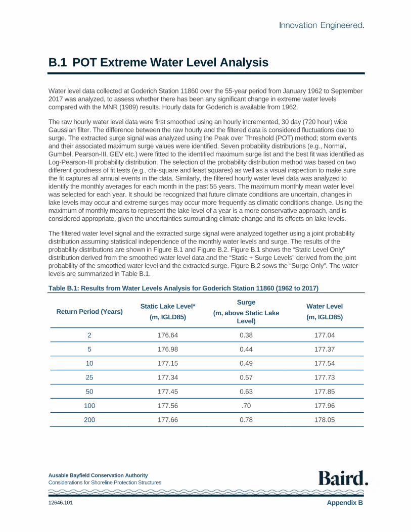
Ausable Bayfield Conservation Authority Considerations for Shoreline Protection Structures
12646.101 Appendix B
B.1 POT Extreme Water Level Analysis
Water level data collected at Goderich Station 11860 over the 55-year period from January 1962 to September 2017 was analyzed, to assess whether there has been any significant change in extreme water levels compared with the MNR (1989) results. Hourly data for Goderich is available from 1962.
The raw hourly water level data were first smoothed using an hourly incremented, 30 day (720 hour) wide Gaussian filter. The difference between the raw hourly and the filtered data is considered fluctuations due to surge. The extracted surge signal was analyzed using the Peak over Threshold (POT) method; storm events and their associated maximum surge values were identified. Seven probability distributions (e.g., Normal, Gumbel, Pearson-III, GEV etc.) were fitted to the identified maximum surge list and the best fit was identified as Log-Pearson-III probability distribution. The selection of the probability distribution method was based on two different goodness of fit tests (e.g., chi-square and least squares) as well as a visual inspection to make sure the fit captures all annual events in the data. Similarly, the filtered hourly water level data was analyzed to identify the monthly averages for each month in the past 55 years. The maximum monthly mean water level was selected for each year. It should be recognized that future climate conditions are uncertain, changes in lake levels may occur and extreme surges may occur more frequently as climatic conditions change. Using the maximum of monthly means to represent the lake level of a year is a more conservative approach, and is considered appropriate, given the uncertainties surrounding climate change and its effects on lake levels.
The filtered water level signal and the extracted surge signal were analyzed together using a joint probability distribution assuming statistical independence of the monthly water levels and surge. The results of the probability distributions are shown in Figure B.1 and Figure B.2. Figure B.1 shows the “Static Level Only” distribution derived from the smoothed water level data and the “Static + Surge Levels” derived from the joint probability of the smoothed water level and the extracted surge. Figure B.2 sows the “Surge Only”. The water levels are summarized in Table B.1.
Table B.1: Results from Water Levels Analysis for Goderich Station 11860 (1962 to 2017)
Return Period (Years) Static Lake Level*
(m, IGLD85)
Surge
(m, above Static Lake Level)
Water Level
(m, IGLD85)
2 176.64 0.38 177.04
5 176.98 0.44 177.37
10 177.15 0.49 177.54
25 177.34 0.57 177.73
50 177.45 0.63 177.85
100 177.56 .70 177.96
200 177.66 0.78 178.05

Ausable Bayfield Conservation Authority Considerations for Shoreline Protection Structures
12646.101 Appendix B
Figure B.1: Probability distributions of static lake level, joint static + surge level at Goderich
Figure B.2: Probability distributions of surge at Goderich

Ausable Bayfield Conservation Authority Considerations for Shoreline Protection Structures
12646.101 Appendix C
Nearshore Lakebed Erosion Summary of Methodology
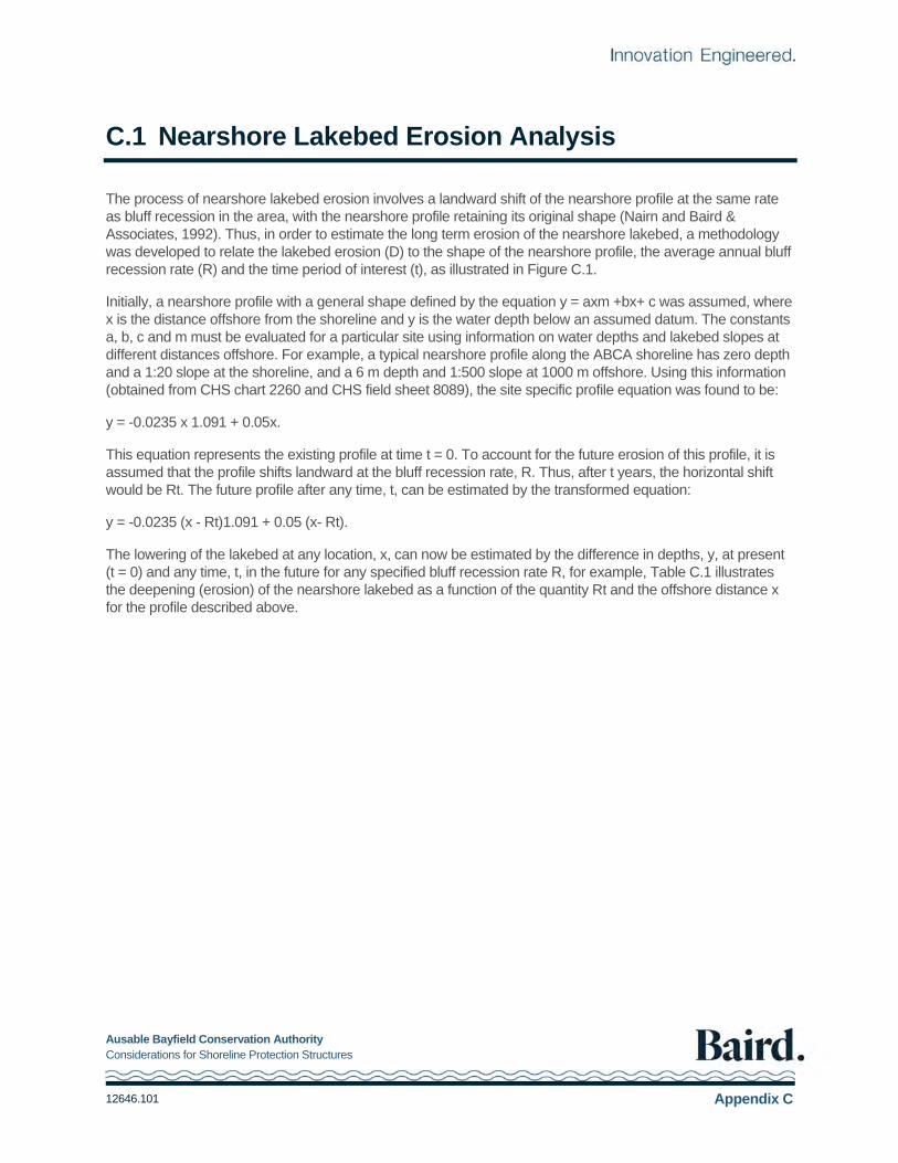
Ausable Bayfield Conservation Authority Considerations for Shoreline Protection Structures
12646.101 Appendix C
C.1 Nearshore Lakebed Erosion Analysis
The process of nearshore lakebed erosion involves a landward shift of the nearshore profile at the same rate as bluff recession in the area, with the nearshore profile retaining its original shape (Nairn and Baird & Associates, 1992). Thus, in order to estimate the long term erosion of the nearshore lakebed, a methodology was developed to relate the lakebed erosion (D) to the shape of the nearshore profile, the average annual bluff recession rate (R) and the time period of interest (t), as illustrated in Figure C.1.
Initially, a nearshore profile with a general shape defined by the equation y = axm +bx+ c was assumed, where x is the distance offshore from the shoreline and y is the water depth below an assumed datum. The constants a, b, c and m must be evaluated for a particular site using information on water depths and lakebed slopes at different distances offshore. For example, a typical nearshore profile along the ABCA shoreline has zero depth and a 1:20 slope at the shoreline, and a 6 m depth and 1:500 slope at 1000 m offshore. Using this information (obtained from CHS chart 2260 and CHS field sheet 8089), the site specific profile equation was found to be:
y = -0.0235 x 1.091 + 0.05x.
This equation represents the existing profile at time t = 0. To account for the future erosion of this profile, it is assumed that the profile shifts landward at the bluff recession rate, R. Thus, after t years, the horizontal shift would be Rt. The future profile after any time, t, can be estimated by the transformed equation:
y = -0.0235 (x - Rt)1.091 + 0.05 (x- Rt).
The lowering of the lakebed at any location, x, can now be estimated by the difference in depths, y, at present (t = 0) and any time, t, in the future for any specified bluff recession rate R, for example, Table C.1 illustrates the deepening (erosion) of the nearshore lakebed as a function of the quantity Rt and the offshore distance x for the profile described above.

Ausable Bayfield Conservation Authority Considerations for Shoreline Protection Structures
12646.101 Appendix C
Figure C.1: Schematic diagram of bluff and nearshore lakebed erosion

Ausable Bayfield Conservation Authority Considerations for Shoreline Protection Structures
12646.101 Appendix C
Table C.1: Erosion of the Nearshore Lakebed for Typical Nearshore Profile
Offshore Distance
x(m)
Existing Water
Depth (m) Future Water Depth (m) vs. Rt
Rt= 1 2 5 10 20 50 100
0 0.00 0.03 0.05 0.11 0.21 0.38 0.82 1.43
15 0.30 0.32 0.33 0.38 0.46 0.61 1.02 1.59
34 0.60 0.61 0.63 0.67 0.74 0.88 1.25 1.78
56 0.90 0.91 0.93 0.97 1.03 1.15 1.49 2.00
80 1.20 1.21 1.22 1.26 1.31 1.43 1.74 2.21
107 1.50 1.51 1.52 1.56 1.61 1.71 2.00 2.45
For example, assuming a bluff recession rate of 0.5 m/yr and a time span of 100 years (i.e. Rt= 50), the water depth at the present shoreline location will increase from Oto 0.82 m over this period (refer to highlighted values in Table C.1). A similar increase in depth would occur with a bluff recession rate of 1.0 m/yr over a period of 50 years (or any other combination of R and t yielding Rt = 50).
Ausable Bayfield Conservation Authority Considerations for Shoreline Protection Structures
12646.101 Appendix D
ABCA Permit Applications for Shore Protection (as of
September 14, 2017)

71108 Morrison Line, RR #3, Exeter, ON N0M 1S5 • Tel: 519-235-2610 • Fax 519-235-1963
September 14, 2017
Checklist for Applications for Shore Protection Applications for shore protection works shall include the following information. Please check that your application includes the following information. When complete, sign and date this checklist and submit it along with your application package to the Ausable Bayfield Conservation Authority for review. Please refer to the ABCA’s information document on making an application for shore protection works for additional detail. Application Form
A completed and signed application form signed by both contractor and landowner must be submitted. There must be a completed application for each property affected.
Letter of Authorization from landowner where authorised agent is seeking permit
Application Fee
Application fees
Drawings / Plans
A scaled and dimensioned plan and profile view of the work site which clearly and accurately shows all of the following:
a.) property identification b.) property boundaries
c.) existing site conditions, including the location of the toe of the lake bank, any existing shore protection, any neighbouring shore protection, stairs decks, structures etc. d.) clear information regarding the design, location and dimensions of the proposed shore protection e.) clear information on how the proposed protection is to be tied into neighbouring protection - if any exists f.) dimensions clearly showing the location and extent of the wall in relation to property lines, existing shore protection, existing toe of the slope etc. g.) the proposed protection is to be clearly shown (and dimensioned to) in relation to permanent existing features which are not subject to disturbance during construction - such as property boundaries.
- rocks and trees are subject to movement and removal and are not suitable features h.) a clear statement indicating that any material, used in the construction and backfilling of the protection, is to be imported to the site and not sourced on site - NO sand or rock is to be removed from the beach and used in the construction of the protection i.) title block showing the date of the drawing or last drawing revision
Supporting Information
A clear statement indicating that any material used in the construction and backfilling of the protection is to be imported to the site and not sourced on site - NO sand or rock removal from the beach is permitted.
The means of access for machinery and materials to the proposed site - any crossing of private property will
require permission of the affected landowners. The Authority may require detailed technical review of a proposal. This may include a coastal engineer’s and
/ or and geotechnical engineer’s review. Please be aware that any such review will be undertaken at the expense of the applicant.
Signature of Applicant Date
If you have any questions regarding the ABCA’s application requirements or its review process please contact the ABCA.
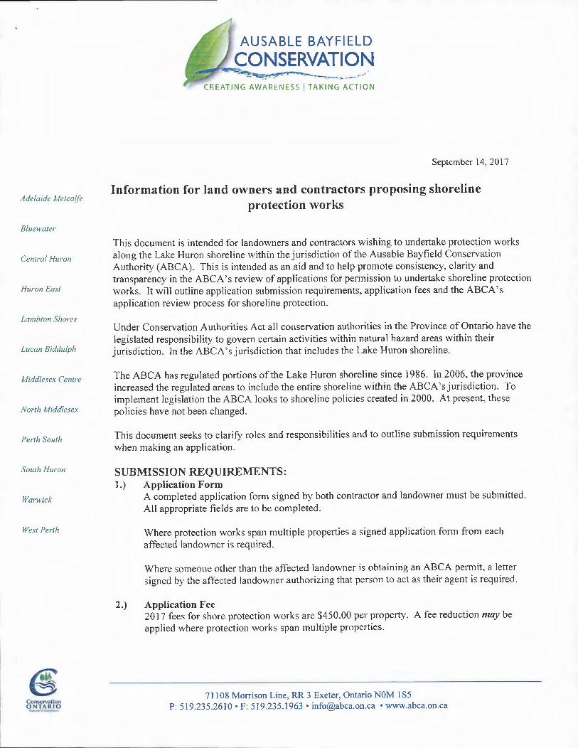
Adelaide A,tetcalfe
Bluewater
Cenlral Huron
Huron Easl
Lambton Shores
Lucan tsiddulph
Middlesex Centre
North Middlesex
Perth South
South Huron
Warwick
West Perth
AUSABLE BAYFIELD
CONSERVATIONCREATING AWARENESS ITAKING ACTION
September 14.2011
Information for land o\ryners and contractors proposing shorelineprotection works
Tlris docunient is intended for landowners and contractors wishing to undertake protection worksalong the Lake Huron shoreline within the jurisdiction of the Ausable Bayfield Conservation
Authority (ABCA). This is intended as an aid and to help promote consistency, clarity and
transparency in the ABCA's review of applications for permission to undertake shoreline protection
works. It will outline application submission requirements, application fees and the ABCA'sapplication review process for shoreline protection.
Under Conservation Authorities Act all conservation authorities in the Province of Ontario have the
legislated responsibility to govern certain activities within natural hazard areas within theirjurisdiction. In the ABCA's jurisdiction tlrat includes the Lake Huron shoreline.
The ABCA has regulated portions of the Lake Huron shoreline since 1986. In 2006, the province
increased the regulated areas to include the entire shoreline within the ABCA's jurisdiction. Toimplement legislation the ABCA looks to shoreline policies created in 2000. At present, these
policies have not been changed.
This document seeks to clarifu roles and responsibilities and to outline submission requirements
when making an application.
SUBMISSION REQUIREMENTS :
l.) Application FormA completed application fonl sigred by both contractor and landowner must be subrnitted.
All appropriate fields are to be conrpleted.
Where protection works span multiple properties a signed application form from eaclr
affected landowner is required.
Where someone otlrer than tlre affected Iandou,ner is obtaining an ABCA permit, a letter
signed by the affected landowner authorizing that person to act as their agent is required.
2.) Application Fee2017 fees for shore protection works are $450.00 per property. A fee reduction malt lsapplied where protectiott works span multiple properties'
71108 Monison Line, RR 3
P:519.235.2610 ' F: 519.235.1963 'Exeter, Ontario NOM 135
[email protected]' www.abca.on.ca

As application fees are set by the ABCA's Board of Directors and may clrange from time to time, pleasecontact ABCA staff for the current application fee.
Appl ication fees are non-refundable.
3.) DrawingsIn order for the ABCA to review a proposal, accurate and complete plans are required. Acceptable plans willprovide ABCA staffwith enough information such that it will have a reasonable understanding of the scopeand location ofthe proposal.
Appropriate plans will include but not be limited to:- a scaled and dimensioned plan and profile view of the work site which clearly and accurately showsthe followins:
a.) pioperty identification including address, plan and lot numberb.) property boundariesc.) existing site conditions, including the location of the toe of the lake bank, any existingshore protection, any neighbouring shore protection, stairs decks, structures, location of anydrains, north arrow, etc.d.) clear information regarding the design, location and dimensions of the proposed shoreprotectione.) clear information on how the proposed protection is to be tied into neighbouringprotection - if any existsf.) dimensiorrs clearly slrowing the location and extent of the wall in relation to property lines,existing shore protection, existing toe of the slope etc.g.) the proposed protection is to be clearly shown (and dimensioned to) in relation topermanent existing features which are not subject to disturbance during construction - such as
property boundaries.- rocks and trees are subject to movement and removal and are not suitable featuresh.) a clear statement indicating that any material, used in the construction and backfilling ofthe protection, is to be imported to the site and not sourced on site - NO sand or rock is to beremoved from the beach and used in the construction of the protectioni.) title block showing the date of the drawing or last drawing revision
In general, the information presented in plans must provide the ABCA with enough information to understandthe design and location of the work prior to construction. The ABCA must also be able to inspect the sitefollowing project completion and confirm construction and location as per the approved design.
The ABCA does have resources, such as air photos, which may help in the preparation of plans. Pleasecontact ABCA staffto discuss resource availability and cost to supply.
Please be aware that ABCA staff is able to provide direction in the preparation of plans, but is unable to helpin gathering site information or in preparing plans.
4.) AdditionalSupportinglnformationThe applicant and or their agent should also submit and other additional supporting information regarding theproposed work. Such infonnation will include:
- the timing of the proposed work- the means of access for machinery and materials to the proposed site - any crossing of privateproperty will require permission of the affected landowners

Applicants for shore protection should be aware that the ABCA is required to review applications with respectto tlreir potential impacts on flooding, erosion and dynamic beaches - not only on the applicant's properly butalso on neighbouring properties. As a result, the Authority may require detailed technical review of aproposal. This may include a coastal engineer's and I or and geotechnical engineer's review. Please be awarethat any suclr review will be undertaken at the expense of the applicant.
PROCESS:To insure consistency, clarity and transparency in its application review process the ABCA will be followingthe guidelines below. These guidelines, including the stated timelines, were established in 2010 by aprovincial committee whose members included representation from multiple stakeholders.
Following receipt of the application described above the ABCA will identif, and confirm, in writing, whetherthe application has been deemed complete or not. Please be aware that substantial changes to a proposal afterreceipt of the application may necessitate changes to the complete application requirements.
If an application is deemed incornplete, the ABCA will provide the applicant with a written list of missingand needed informatiorr.
During the review of an application to determine its completeness, the ABCA may request additionalinformation if it deems an application does not contain sufficient technical analysis. Delays in timelines formaking a decision may occur due to ABCA requests for additional information to address errors or gaps ininformation submitted for review. An application can be put on hold or returned to the applicant pending thereceipt of the additional requested information.
Subsequent to receipt of a complete application, delays in timelines for a decision on an application mayoccur due to ABCA requests for additional information to address errors or gaps in technical informationsubmitted for review. Applications can be put on hold or returned to the applicant pending the receipt offurlher information to avoid premature refusals of applications due to inadequate information.
Staffof the ABCA is only able to issue a permit when it is determined that an application is permitted byapproved policies. Staffcan not approve an application that does not meet ABCA policy. Similarly, ABCAstaff is unable to deny an application. In cases where an applicant is either unable or unwilling to amend an
application to bring it into conformity with approved policies or is unable or unwilling to submit requested
technical information the application will be referred to a Hearing under the Conservation Authorities Act.
If you have any questions regarding the ABCA's application requirements or its review process please contact the
ABCA.
Ausable Bayfi eld Conservation Authority71108 Morrison LineR.R. # 3, Exeter, Ontario519-235-2610