
Considerations For Re-Cladding Highrise Panelized …€¦ · ABSTRACT Considerations For...
16
ABSTRACT Considerations For Re-Cladding Highrise Panelized EIFS Buildings – A Case Study David G. Kayll, FMA, P.Eng. 1 An eight year old, highrise building in a Canadian cold climate zone was diagnosed with systematic water penetration through the Exterior Insulation and Finish System (“EIFS”) building envelope. This building utilized a factory-manufactured, modular panelized cladding system for the exterior walls that included EIFS building envelope components. The original panel design had some components intended to perform as a “drained” system which, when coupled with a factory controlled manufacturing environment, is normally considered a lower risk, good practice approach. Nevertheless, there was water penetration into the interior, with resulting water damage and related environmental problems to panel structural components and interior finishes. This building has undergone a large-scale exterior re-cladding in the affected areas. The repair involves the removal of all exterior wall building envelope components, a re-design of the building envelope system that includes the use of a new drained EIFS approach, and the installation of the new wall system on the building. All rehabilitation work was completed while the building remained operational. This paper describes the methods used to re-clad the facility while maintaining the mandated original appearance. Key discussion will focus on how the new EIFS system was designed, and how it was constructed to address reasonable durability expectations. Content will also focus on how designers and builders can improve the actual performance of these systems “as installed” to reduce the risks commonly associated with highrise EIFS. The benefits of this paper to the reader will hope to include; discussion of real-world application of panelized EIFS design concepts, identification of factors not always considered in the design and installation of these systems, practical advice on methods for improving performance while managing potential risks, and considerations for the application of this approach on other projects. KEYWORDS: building envelope, building science, panelized construction, EIFS, water penetration, rainscreen, re-cladding, rehabilitation, cold climate, design, risk management. 1 David Kayll, FMA, P.Eng., is a Principal and Building Science Engineer at Morrison Hershfield Limited based in the Ottawa, Ontario office. 11 th Canadian Conference on Building Science and Technology Banff, Alberta, 2007
Transcript of Considerations For Re-Cladding Highrise Panelized …€¦ · ABSTRACT Considerations For...
ABSTRACT
Considerations For Re-Cladding Highrise Panelized EIFS Buildings – A Case Study
David G. Kayll, FMA, P.Eng.1
An eight year old, highrise building in a Canadian cold climate zone was diagnosed with systematic water penetration through the Exterior Insulation and Finish System (“EIFS”) building envelope. This building utilized a factory-manufactured, modular panelized cladding system for the exterior walls that included EIFS building envelope components. The original panel design had some components intended to perform as a “drained” system which, when coupled with a factory controlled manufacturing environment, is normally considered a lower risk, good practice approach. Nevertheless, there was water penetration into the interior, with resulting water damage and related environmental problems to panel structural components and interior finishes.
This building has undergone a large-scale exterior re-cladding in the affected areas. The repair involves the removal of all exterior wall building envelope components, a re-design of the building envelope system that includes the use of a new drained EIFS approach, and the installation of the new wall system on the building. All rehabilitation work was completed while the building remained operational.
This paper describes the methods used to re-clad the facility while maintaining the mandated original appearance. Key discussion will focus on how the new EIFS system was designed, and how it was constructed to address reasonable durability expectations. Content will also focus on how designers and builders can improve the actual performance of these systems “as installed” to reduce the risks commonly associated with highrise EIFS.
The benefits of this paper to the reader will hope to include; discussion of real-world application of panelized EIFS design concepts, identification of factors not always considered in the design and installation of these systems, practical advice on methods for improving performance while managing potential risks, and considerations for the application of this approach on other projects.
KEYWORDS: building envelope, building science, panelized construction, EIFS, water penetration, rainscreen, re-cladding, rehabilitation, cold climate, design, risk management.
1 David Kayll, FMA, P.Eng., is a Principal and Building Science Engineer at Morrison
Hershfield Limited based in the Ottawa, Ontario office.
11th Canadian Conference on Building Science and Technology Banff, Alberta, 2007
Considerations For Re-Cladding Highrise Panelized EIFS Buildings – A Case Study
David G. Kayll, FMA, P.Eng.
INTRODUCTION
A highrise building was assessed recently and found to be experiencing water penetration problems through the exterior cladding. The water penetration problems had been noted for a number of years and various attempts had already been made to rectify the problems. During the review of the existing conditions and available documentation it is discovered that the building uses a pre-manufactured panel system with Exterior Insulation and Finish System (“EIFS”) as the exterior cladding.
It was determined that the most reasonable course of action was to re-clad the building. The new cladding system design had to address the causes of the water penetration and provide an economical, constructible, durable system suitable for its climate. The client required that the replacement envelope had to resemble the existing building while the facility remained in operation throughout the work.
This presented an unusual challenge to the design team given the unique elements of the field installation of a replacement system onto an original system that utilized pre-manufactured panels, in a continuously operating facility.
THE EXISTING SYSTEM
The original building envelope was developed to incorporate a project-specific, pre-manufactured panel system that integrated the structural requirements of the exterior wall with the weather management system in a manner that allowed for factory construction. Each panel was then delivered to site and installed by crane onto the building.
THE THEORY
The concept mirrors that of architectural pre-cast concrete panel systems and is generally intended to provide the following benefits to a project:
Quality Control – The ability to focus the manufacturing process within the confines of a factory environment is intended to enable greater quality control over the application of the various components of the wall system.
Consistent Environmental Conditions - The elimination of the negative impacts of weather during construction provides for greater quality control over both construction trade forces and materials that are normally sensitive to cold and/or wet conditions. This is especially important with the materials used in the construction of an EIFS exterior cladding.
Ease of Construction – By constructing the panels within a factory environment, the complications associated with field construction are removed. For example, overlap of unrelated trades is removed, jigs can be developed to both speed construction and improve accuracy, access is greatly simplified, weather has little impact as noted above, etc.
11th Canadian Conference on Building Science and Technology Banff, Alberta, 2007
Construction Schedule - Panel construction off the critical construction path can provide a faster overall construction schedule. Panels can begin construction long before the site is ready for their installation. Panels can also be selectively constructed and installed to suit the particular needs of the site (for example, around special features), thus enhancing the overall construction schedule.
Compartmentalization – Using individual panels, the exterior cladding system can be designed to effectively compartmentalize the exterior wall into a collection of individually isolated sections, to theoretically improve the weather management characteristics of the overall building envelope. The term compartmentalization is often used when discussing air pressure modulation in a pressure equalized rainscreen system. However, in panelized wall construction, it can also refer to the isolation of the impacts of localized failure as a means to limit the resulting damage.
The overall success of a wall system is directly dependent upon the design and construction of the interface details. In a panelized approach, there are interfaces between each panel that are not normally encountered in more traditional construction techniques and the treatment of these interfaces has a direct impact on the performance of the wall. Better performance can be achieved if these interface detail requirements are incorporated into the panel design. When rehabilitating a panelized design, the development of suitable interface detailing that can be applied in the field creates interesting challenges, from both a design and “constructability” perspective, as the benefits noted above are not available.
THE REALITY
For the specific project referenced throughout this paper, the section through the original panelized cladding system, shown in Figure 1, was as follows (from interior to exterior):
Vinyl wall covering 13mm (½”) interior gypsum drywall 6 mil polyethylene vapour barrier 90 mm (4”) steel studs of various gauges with glass fibre batt insulation between the
studs Glass fibre coated exterior gypsum board wall sheathing Exterior Insulation and Finish System (“EIFS”), which includes:
- Secondary weather barrier trowel-applied on the sheathing - Insulation adhesive - Expanded polystyrene insulation boards (“EIFS foam”), in thicknesses varying from
50mm to 100mm to reflect the desired design aesthetic - EIFS lamina (base coat, mesh and finish coat)
The EIFS foam was installed using a ribbon and dab method, with an assumed intent of providing a drainable space between the trowel-applied secondary membrane and the EIFS foam. Continuous ribbons of adhesive were to be applied at the top of each window in a sloped pattern with the intent of deflecting water around the jambs, and in a sloped pattern at the bottom of the panels to channel water towards a small drainage block integrated within the EIFS foam.
Panel-to-panel joints were sealed using a combination of compressible foam air seal at the panel perimeters along the steel stud/track interfaces, and a backer rod and sealant joint at the face of the panels. A weep hole was left in the sealant joint to allow for potential drainage from the EIFS drainage block.
11th Canadian Conference on Building Science and Technology Banff, Alberta, 2007
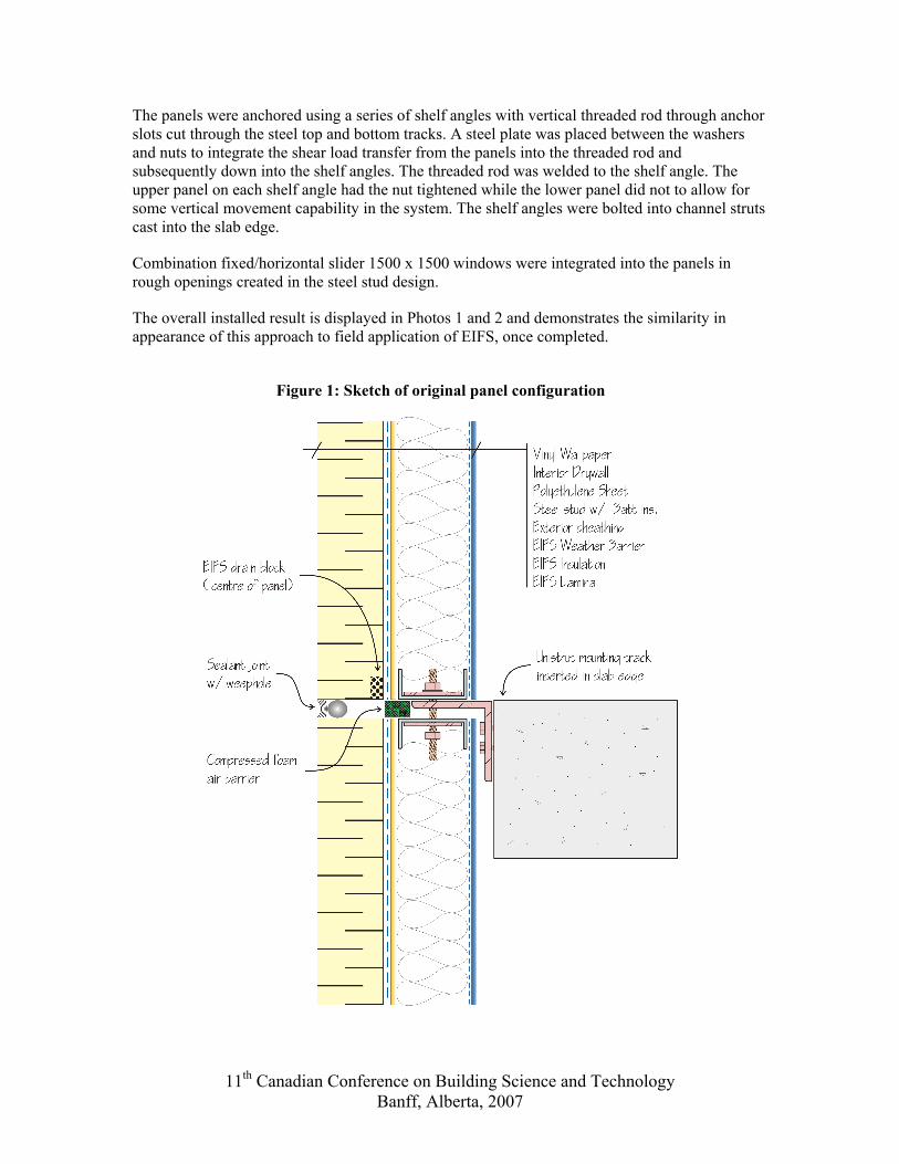
The panels were anchored using a series of shelf angles with vertical threaded rod through anchor slots cut through the steel top and bottom tracks. A steel plate was placed between the washers and nuts to integrate the shear load transfer from the panels into the threaded rod and subsequently down into the shelf angles. The threaded rod was welded to the shelf angle. The upper panel on each shelf angle had the nut tightened while the lower panel did not to allow for some vertical movement capability in the system. The shelf angles were bolted into channel struts cast into the slab edge.
Combination fixed/horizontal slider 1500 x 1500 windows were integrated into the panels in rough openings created in the steel stud design.
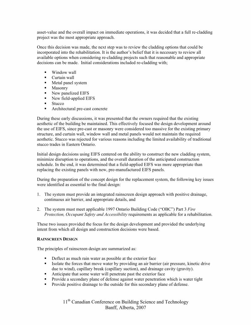
The overall installed result is displayed in Photos 1 and 2 and demonstrates the similarity in appearance of this approach to field application of EIFS, once completed.
Figure 1: Sketch of original panel configuration
11th Canadian Conference on Building Science and Technology Banff, Alberta, 2007
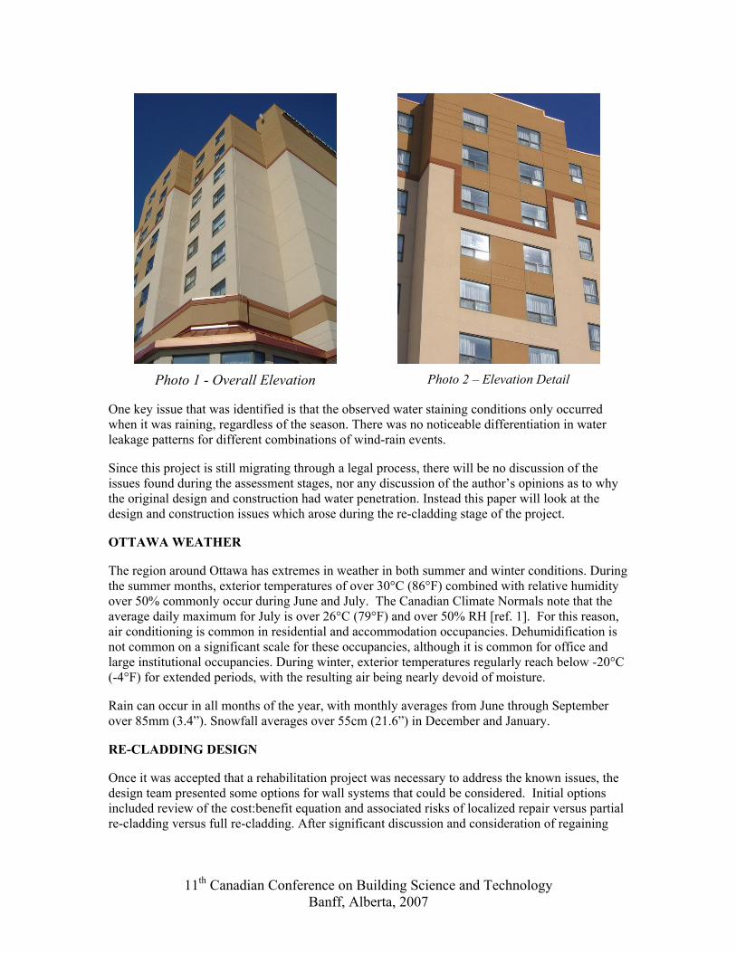
Photo 1 - Overall Elevation
Photo 2 – Elevation Detail
One key issue that was identified is that the observed water staining conditions only occurred when it was raining, regardless of the season. There was no noticeable differentiation in water leakage patterns for different combinations of wind-rain events.
Since this project is still migrating through a legal process, there will be no discussion of the issues found during the assessment stages, nor any discussion of the author’s opinions as to why the original design and construction had water penetration. Instead this paper will look at the design and construction issues which arose during the re-cladding stage of the project.
OTTAWA WEATHER
The region around Ottawa has extremes in weather in both summer and winter conditions. During the summer months, exterior temperatures of over 30°C (86°F) combined with relative humidity over 50% commonly occur during June and July. The Canadian Climate Normals note that the average daily maximum for July is over 26°C (79°F) and over 50% RH [ref. 1]. For this reason, air conditioning is common in residential and accommodation occupancies. Dehumidification is not common on a significant scale for these occupancies, although it is common for office and large institutional occupancies. During winter, exterior temperatures regularly reach below -20°C (-4°F) for extended periods, with the resulting air being nearly devoid of moisture.
Rain can occur in all months of the year, with monthly averages from June through September over 85mm (3.4”). Snowfall averages over 55cm (21.6”) in December and January.
RE-CLADDING DESIGN
Once it was accepted that a rehabilitation project was necessary to address the known issues, the design team presented some options for wall systems that could be considered. Initial options included review of the cost:benefit equation and associated risks of localized repair versus partial re-cladding versus full re-cladding. After significant discussion and consideration of regaining
11th Canadian Conference on Building Science and Technology Banff, Alberta, 2007
asset-value and the overall impact on immediate operations, it was decided that a full re-cladding project was the most appropriate approach.
Once this decision was made, the next step was to review the cladding options that could be incorporated into the rehabilitation. It is the author’s belief that it is necessary to review all available options when considering re-cladding projects such that reasonable and appropriate decisions can be made. Initial considerations included re-cladding with;
Window wall Curtain wall Metal panel system Masonry New panelized EIFS New field-applied EIFS Stucco Architectural pre-cast concrete
During these early discussions, it was presented that the owners required that the existing aesthetic of the building be maintained. This effectively focused the design development around the use of EIFS, since pre-cast or masonry were considered too massive for the existing primary structure, and curtain wall, window wall and metal panels would not maintain the required aesthetic. Stucco was rejected for various reasons including the limited availability of traditional stucco trades in Eastern Ontario.
Initial design decisions using EIFS centered on the ability to construct the new cladding system, minimize disruption to operations, and the overall duration of the anticipated construction schedule. In the end, it was determined that a field-applied EIFS was more appropriate than replacing the existing panels with new, pre-manufactured EIFS panels.
During the preparation of the concept design for the replacement system, the following key issues were identified as essential to the final design:
1. The system must provide an integrated rainscreen design approach with positive drainage, continuous air barrier, and appropriate details, and
2. The system must meet applicable 1997 Ontario Building Code (“OBC”) Part 3 Fire Protection, Occupant Safety and Accessibility requirements as applicable for a rehabilitation.
These two issues provided the focus for the design development and provided the underlying intent from which all design and construction decisions were based.
RAINSCREEN DESIGN
The principles of rainscreen design are summarized as:
Deflect as much rain water as possible at the exterior face Isolate the forces that move water by providing an air barrier (air pressure, kinetic drive
due to wind), capillary break (capillary suction), and drainage cavity (gravity). Anticipate that some water will penetrate past the exterior face Provide a secondary plane of defense against water penetration which is water tight Provide positive drainage to the outside for this secondary plane of defense.
11th Canadian Conference on Building Science and Technology Banff, Alberta, 2007
It is one thing to have an EIFS system brochure that states, “This is a rainscreen system”. It is quite another to integrate the fundamentals of that system’s fundamental approach with an existing wall design and other cladding components. Providing an appropriate design that could provide a functional envelope with reasonable durability expectations necessitates careful attention to detailing of all components [ref. 2, 3]. Reasonable design practice for a successful rainscreen design incorporates careful attention to all four cladding functions:
1. Water Barrier
It is the authors’ experience that the most consistently damaging form of moisture in exterior walls in Canada is rainwater. The three most prominent forces that move rainwater are gravity, kinetic energy, and differential air pressure. Therefore, any rehabilitation design must address these forces and the water source directly. For over 40 years the description of the most appropriate means for addressing these forces and source of moisture has been the “open rain screen” design approach, as presented by Kirby Garden in CBD-40: Rain Penetration and Its Control [ref. 4].
The approach used for an EIFS building envelope system must accept that the EIFS lamina of basecoat, mesh and finish coat is the primary water shedding layer. Cracks and discontinuities at interfaces will allow water to penetrate behind the exterior face of the EIFS. The system must anticipate this and ensure that this water does not cause damage to wall components. Most EIFS manufacturers now provide a secondary weather barrier component integrated into a two-part moisture defense. But the intercepted water at the secondary weather barrier location is not harmless until it is safely directed back to the exterior. Many failures of rainscreen wall designs occur when insufficient attention is paid to the design and construction of the moisture drainage, especially at the details [ref. 5].
The drain cavity provided in rainscreen EIFS systems ranges from a small space created by the use of vertical ribbons of EIFS foam adhesive, to routed channels in the EIFS foam coupled with these vertical adhesive ribbons. The nominal cavity dimension for the vertical ribbon only systems is between 1mm and 3mm, whereas the cavity dimension is between 2mm and 8 mm for systems using routed channels. The design team reviewed some of the available literature on the performance of these drained systems, but was not convinced of the effectiveness of the vertical ribbon only systems. This is largely due to the dependence of these systems on a nearly perfectly flat attachment plane to ensure that drainage paths are not obscured. It is the author’s experience that construction realities are rarely perfect and this would be especially difficult to provide as part of a rehabilitation project. It was determined that systems that used routed channels coupled with vertical adhesive ribbons would be the only acceptable approach for this project.
Panelized systems add some complexity to moisture drainage design. Each existing panel is, in effect, an independent wall section and has to be treated in that manner. Early in the design development of this project, it was decided that the rainscreen EIFS would have a throughwall flashing installed at the bottom of each panel. The intent would be to positively direct incidental water that may penetrate to the secondary barrier directly to the exterior of each panel without re-directing it internally within the envelope. It was also decided that draining each panel section would reduce the complexity of integrating drainage paths from panel to panel.
Fundamental to the success of a rainscreen water drainage design was the development of functional window water management details. Fundamental decisions were made to protect the entire rough opening against water damage and drain the rough opening to the exterior at the sill level and not into the EIFS drainage cavity. Each window therefore had a sub-sill flashing
11th Canadian Conference on Building Science and Technology Banff, Alberta, 2007
arrangement integrated with the continuity of the air barrier and thermal protection components of the design. Exterior sealant between the windows and wall was to be used as the primary water shedding surface and as an aesthetic finish.
The owners wished to retain the existing windows. This decision did not cause undue concern since the water management design approach would have remained largely the same regardless of whether new windows were used.
2. Air Barrier
Most modern EIFS systems utilize the secondary weather barrier as the primary air barrier component of the wall design. From a theoretical perspective this is sensible since this plane is also acting as the final water barrier and must therefore prevent air-pressure driven water from moving across it. This is also practical as this secondary weather barrier is most often directly applied to the exterior sheathing or masonry back-up wall.
The critical concept for successful air barrier design is focused attention on interface detailing – ensuring continuity of air barrier integrity across the air pressure gradients expected. For an EIFS field rehabilitation of a modular panelized system this means that careful attention is required for air barrier continuity from panel-to-panel, noting the relationships between trowel-applied membranes, sheet membranes, throughwall flashing, penetrations such as windows, and finish materials.
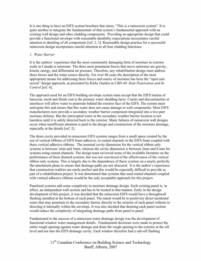
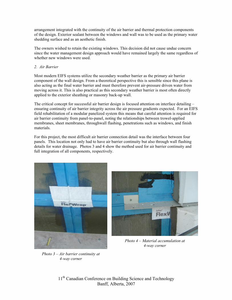
For this project, the most difficult air barrier connection detail was the interface between four panels. This location not only had to have air barrier continuity but also through wall flashing details for water drainage. Photos 3 and 4 show the method used for air barrier continuity and full integration of all components, respectively.
Photo 3 – Air barrier continuity at
4-way corner
Photo 4 – Material accumulation at
4-way corner
11th Canadian Conference on Building Science and Technology Banff, Alberta, 2007
There is a need to look at the impacts of the construction process, where multiple penetrations through the air barrier plane are necessary until the very end of the construction period, eg., scaffolding anchors and braces. These penetrations require specific details that are often not definable until the construction has begun, since the design team will not know where these attachment points will be made.
3. Vapour Barrier
Control of vapour movement is relatively easy to manage, given that vapour is driven by differential vapour pressure, and that materials to intercept this movement are relatively well known and reasonably easy to install for the function they are intended to provide.
For this project, the original wall design included vinyl wallpaper as the interior finish. This approach was to continue, which established the location of the primary vapour barrier during the cold weather months, when the predominant vapour pressure gradient is from inside to outside.
Interestingly, the original design also included a polyethylene sheet vapour barrier material directly behind the interior gypsum drywall. There was little need for this material as a vapour barrier since the use of the vinyl wallpaper effectively provided this function. However, it may have been included by the original designer to ensure some form of vapour control was in place should the owners change the type of interior finish. We decided to retain the polyethylene as well for the same reasons. It should be noted that the existing polyethylene was not installed in a manner consistent with its use as an air barrier as there were no attempts to provide continuity from panel-to-panel or to provide structural support for the expected wind pressure loads.
Although the summer months provide some significant temperature highs coupled with high air moisture contents, the lack of dehumidification of the interior air for this facility means that the net inward moving vapour pressure gradient across the envelope not significant over extended periods of time. The exterior cladding choice was EIFS, with a relatively low vapour permeance, ranging between 40 and 80 ng/Pa·s·m2 for 75mm foam EIFS with lamina and secondary weather barrier layers combined. Therefore, any short-term vapour gradient from outside to inside would be effectively managed.
4. Thermal Barrier
Heat flow management is an important concept in a location where exterior temperatures regularly reach –20°C (-4°F) in winter. Minimizing heat loss is important since heat energy is relatively expensive and energy use contributes to global warming through carbon dioxide gas emissions. The original design resisted heat loss with glass fibre batt insulation within the steel stud wall plus the thermal resistance value provided by the EIFS foam. The architectural design of the exterior cladding utilized a range of EIFS foam thicknesses, from 50mm (2”) to 100mm (4”) to create relief and the visual aesthetic. The predominant thickness was 75mm (3”).
The theoretical thermal resistance of the original wall design ranged from RSI 4.2 to RSI 5.7 (R24 to R32) through the batt insulation in the steel stud wall, depending upon EIFS foam thickness. However, it is important to note that a 90mm steel stud wall with batt insulation has an overall thermal resistance of approximately 55% of the through-the-insulation value [ref. 6]. When adjusted for this fact, the theoretical values ranged from RSI 3.1 to RSI 4.5 (R18 to R26), with over 50% of this value coming from the EIFS foam. The thermal performance of the EIFS foam is important for the overall performance of the wall system, both from a comfort and a condensation control perspective.
11th Canadian Conference on Building Science and Technology Banff, Alberta, 2007
The new EIFS system was to include a drained cavity created by routed channels in the EIFS foam coupled with vertical ribbons of foam adhesive. From a thermal perspective, the design team wanted to explore whether this cavity space significantly affected the thermal resistance value provided by the EIFS foam to a point where complications within the wall design may occur. For this project the drainage cavity was to be compartmentalized by sealing the top and sides of the cavity within each panel. The design team therefore assumed that the loss of thermal resistance was not likely significant but we wanted to confirm this assumption.
Considerable effort was expended reviewing information on what is known of this potential phenomenon yet we did not find any concrete evidence or research published on this issue. Some industry experts informally suggested to the author that perhaps a 10% reduction in thermal performance may be appropriate, although this is by no means confirmed. If this were the case, the thermal resistance of the walls would be reduced to between RSI 3.0 and RSI 4.3, with a majority of the wall at RSI 3.6 (R21). For his latter value, the EIFS foam provides 53% percent of the thermal resistance. The author believes that there would be value added to the design community if some quantification of the real thermal impact of the drainage cavity in drained EIFS systems was researched and published.
BUILDING CODE FIRE AND LIFE SAFETY ISSUES
The building is nine storeys high, seven of which are rooms and suites and the bottom two contain meeting rooms, swimming pool, restaurant, and common service areas. Therefore, the 1997 Ontario Building Code mandates non-combustible construction. OBC Article 3.1.5.5 notes that combustible cladding components are allowed in a non-combustible construction as long as the building is not more than six storeys and sprinklered. However, Sentence (6) of this Article notes that this does not apply for foamed plastic insulation on the exterior walls as long as it is protected in accordance with Sentences 3.2.3.7 (7) and (8). These latter sentences state that foamed plastic insulation is allowed for buildings over three storeys when the cladding complies;
“…with the criteria for testing and conditions of acceptance of Sentence (8) when testing in conformance with CAN/ULC-S101-M, “ Standard Methods for Fire Endurance Tests of Building Construction and Materials.”[ref. 7]
Sentence (8) provides the testing and acceptance criteria for the satisfaction of the above requirement. In effect, although EIFS foam is considered a combustible element in a cladding that is intended to be non-combustible, if the EIFS system passes the CAN/ULC S101 test using the noted criteria, it is considered non-combustible for the purposes of the Code and may be used on a building of this type.
This meant that any manufacturer’s EIFS system that was to be considered for use on the rehabilitation must have been tested and passed the CAN/ULC S101 test using the noted criteria. Therefore, current documentation of successful testing for specific drained EIFS systems became a key element during design development.
What is important to note is that most EIFS manufacturers have many different systems, and many components of these systems that can be mixed and matched to achieve certain designer-specific objectives. However, most EIFS manufacturers do not submit all of the various combinations of materials for CAN/ULC S101 testing as combined systems. Therefore, it is incumbent on the designer to ensure that the system used for a design is the system documented as having passed the CAN/ULC S101 test. Critical to this objective is ensuring that the as-tested specifications for all system components are integrated into the design, such as back-up wall
11th Canadian Conference on Building Science and Technology Banff, Alberta, 2007

materials and dimensions (i.e., sheathing), secondary weather barrier materials and thicknesses, mesh weights and composition, foam density and thickness limitations, EIFS lamina coating materials and thicknesses, etc.
For this project, there were very few rainscreen systems that met the above criterion. In fact, this was the most important criterion for the final selection of EIFS system for the rehabilitation and governed to a meaningful extent the design decisions that were made from a building science perspective. For example, there are a number of different secondary weather barrier materials available from EIFS suppliers. Some of these have a low vapour permeance and may be desirable for this trait from a design perspective. However, these membranes were not tested for the CAN/ULC S101 criteria and were therefore not appropriate for the project.
CCMC
It was determined that a Canadian Construction Materials Centre (CCMC) evaluation of the specific system to be used was necessary to provide general compliance with Code requirements and ensure that the system used was independently evaluated to perform in the manner claimed. This meant that for EIFS systems, the CCMC testing was to include all components, such as; back-up wall, secondary weather barrier, EIFS foam adhesive, foam and lamina components.
The system evaluations must reference the specific details on material use, coating thicknesses, structural requirements, etc., which can then referenced directly in the design documentation. It is important to observe differences between the CCMC evaluation report and the EIFS manufacturer’s “standard specifications”. As with the CAN/ULC S101 fire testing discussed above, there is often a wide range of material choices from manufacturers, and not all combinations will necessarily have been evaluated.
DESIGN DEVELOPMENT
This combination of requirements quickly focuses attention on the available systems open to the design team for use.
Each layer in the EIFS cladding design requires specific attention to ensure proper requirements are provided. All components from the back-up wall construction, through sheathing and EIFS system will need design attention to integrate the multiple performance requirements of weather barrier, fire safety, and structure. The designer must research items like:
Steel stud design for gravity and wind loads to also include the limited deflection requirements of the EIFS cladding.
Exterior sheathing layout to ensure proper detailing around openings. Exterior sheathing attachment to manage wind load expectations. Secondary weather barrier installation sequencing to ensure proper thicknesses and
material coverage, as well as continuity. Continuity details across panels for proper performance and differential movement. EIFS foam adhesive installation to ensure consistent and uniform attachment. Installation sequencing to ensure material integration at windows and other details.
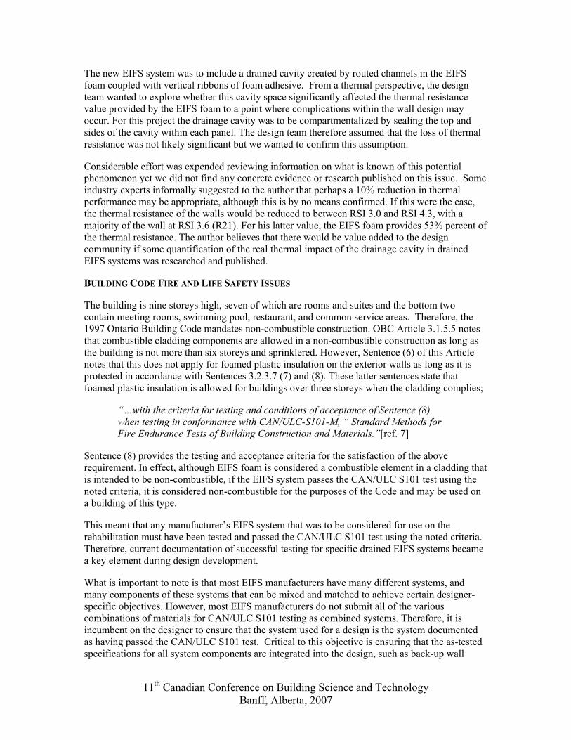
The rehabilitation design for the final construction is presented in schematic form in Figure 2. Note the multiple layers that occur at the through wall flashing location. This accumulation of materials was a consequential issue as the extra 3 mm of self-adhesive membrane and metal flashing affects the adhesion of the EIFS foam at the edges and pushes the foam outwards.
11th Canadian Conference on Building Science and Technology Banff, Alberta, 2007
Mechanical fasters were added along the bottom edges to ensure proper attachment, and careful shaping of the bottom edge foam was integrated into the construction sequencing.
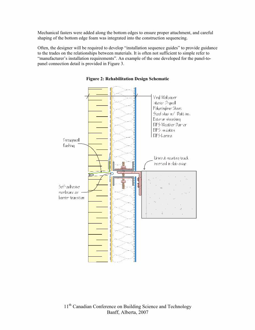
Often, the designer will be required to develop “installation sequence guides” to provide guidance to the trades on the relationships between materials. It is often not sufficient to simple refer to “manufacturer’s installation requirements”. An example of the one developed for the panel-to-panel connection detail is provided in Figure 3.
Figure 2: Rehabilitation Design Schematic
11th Canadian Conference on Building Science and Technology Banff, Alberta, 2007
Figure 3: Sample Panel-to-Panel Connection Installation Sequence Guide
CONSTRUCTION CONDITIONS
OPERATIONAL FACILITY
Rehabilitation design differs from new design in many ways, with one of the most significant influence being the fact that a rehabilitated facility may remain occupied. In the case of this project, not only would the facility continue to be occupied, but the occupants were the public. Therefore, the exposures and risks to the owners, the designers and the contractors are elevated significantly, as the duty to protect the public influences all decisions.
Inherent in these decisions is the need to provide solutions that can be effectively constructed in limited time frames. For instance, when a wall area is dismantled, it must be possible to effectively re-establish the building envelope in as short a period as possible to minimize the impact on operations. This can have a significant impact on design considerations since the sequence of demolition and re-construction becomes critical to design choices.
Management of the expectations and concerns of the operators and clients, especially around the concerns for risk elements like safety and mold, are critical. As part of the design documentation, a full section of the specifications was dedicated to the remediation requirements for mold. Once construction was underway, a detailed mold remediation protocol was also developed that outlined the sequence of events to occur within each room for the containment, demolition and removal of potentially mold-contaminated materials.
HIDDEN CONDITIONS
Although most designs of relatively simple structures are similar and predictable, no two facilities are constructed exactly alike. Hidden gems reflecting on-site conditions or the quality management of trade construction directly impact the ability of any rehabilitation design to
11th Canadian Conference on Building Science and Technology Banff, Alberta, 2007
adequately perform. Just because it is drawn as a straight line in the design and original as-builts does not mean that it will be that way on-site. The rehabilitation design must allow for flexibility.
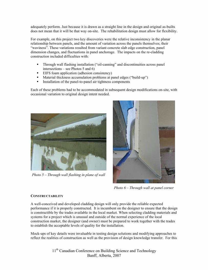
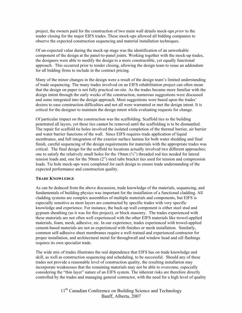
For example, on this project two key discoveries were the relative inconsistency in the planar relationship between panels, and the amount of variation across the panels themselves; their “waviness”. These variations resulted from variant concrete slab edge construction, panel dimension changes, and fluctuations in panel anchorage. The impacts on the re-cladding construction included difficulties with:
Through wall flashing installation (“oil-canning” and discontinuities across panel intersections – see Photos 5 and 6)
EIFS foam application (adhesion consistency) Material thickness accumulation problems at panel edges (“build-up”) Installation of the panel-to-panel air tightness components
Each of these problems had to be accommodated in subsequent design modifications on-site, with occasional variation to original design intent needed.
Photo 5 – Through wall flashing in plane of wall
Photo 6 – Through wall at panel corner
CONSTRUCTABILITY
A well-conceived and developed cladding design will only provide the reliable expected performance if it is properly constructed. It is incumbent on the designer to ensure that the design is constructible by the trades available in the local market. When selecting cladding materials and systems for a project which is unusual and outside of the normal experience of the local construction market, the designer (and owner) must be prepared to work together with the trades to establish the acceptable levels of quality for the installation.
Mock-ups of key details were invaluable in testing design solutions and modifying approaches to reflect the realities of construction as well as the provision of design knowledge transfer. For this
11th Canadian Conference on Building Science and Technology Banff, Alberta, 2007
project, the owners paid for the construction of two main wall details mock-ups prior to the tender closing for the major EIFS trades. These mock-ups allowed all bidding companies to observe the expected construction sequencing and material installation techniques.
Of un-expected value during the mock-up stage was the identification of an unworkable component of the design at the panel-to-panel joints. Working together with the mock-up trades, the designers were able to modify the design to a more constructible, yet equally functional approach. This occurred prior to tender closing, allowing the design team to issue an addendum for all bidding firms to include in the contract pricing.
Many of the minor changes in the design were a result of the design team’s limited understanding of trade sequencing. The many trades involved on an EIFS rehabilitation project can often mean that the design on paper is not fully practical on-site. As the trades became more familiar with the design intent through the early weeks of the construction, numerous suggestions were discussed and some integrated into the design approach. Most suggestions were based upon the trades’ desires to ease construction difficulties and not all were warranted or met the design intent. It is critical for the designer to maintain the design intent while evaluating requests for change.
Of particular impact on the construction was the scaffolding. Scaffold ties to the building penetrated all layers, yet these ties cannot be removed until the scaffolding is to be dismantled. The repair for scaffold tie holes involved the isolated completion of the thermal barrier, air barrier and water barrier functions of the wall. Since EIFS requires trade application of liquid membranes, and full integration of the exterior surface lamina for both water shedding and final finish, careful sequencing of the design requirements for materials with the appropriate trades was critical. The final design for the scaffold tie locations actually involved two different approaches; one to satisfy the relatively small holes for the 19mm (¾”) threaded rod ties needed for lateral tension loads and, one for the 50mm (2”) steel tube bracket ties used for tension and compression loads. Tie hole mock-ups were completed for each design to ensure trade understanding of the expected performance and construction quality.
TRADE KNOWLEDGE
As can be deduced from the above discussion, trade knowledge of the materials, sequencing, and fundamentals of building physics was important for the installation of a functional cladding. All cladding systems are complex assemblies of multiple materials and components, but EIFS is especially sensitive as most layers are constructed by specific trades with very specific knowledge and experience. For instance, the back-up wall component is either steel stud and gypsum sheathing (as it was for this project), or block masonry. The trades experienced with these materials are not often well experienced with the other EIFS materials like trowel-applied materials, foam, mesh, adhesive, etc. In our experience, trades experienced with trowel-applied cement-based materials are not as experienced with finishes or mesh installation. Similarly, common self-adhesive sheet membranes require a well-trained and experienced contractor for proper installation, and architectural metal for throughwall and window head and sill flashings requires its own specialist trade.
The wide mix of trades illustrates the real dependence that EIFS has on trade knowledge and skill, as well as construction sequencing and scheduling, to be successful. Should any of these trades not provide a reasonable level of construction quality, the resulting installation may incorporate weaknesses that the remaining materials may not be able to overcome, especially considering the “thin layer” nature of an EIFS system. The inherent risks are therefore directly controlled by the trades and managing general contractor, with the need for a high level of quality
11th Canadian Conference on Building Science and Technology Banff, Alberta, 2007
control. This latter point directly points to the inherent weakness in the “lowest bid” approach to tendering, where offsetting emphases on quality and cost control can upset well-balanced design intent.
THE RIGHT SOLUTION?
There are many designers, contractors, insurers and building warranty providers who do not support the use of EIFS as a suitable wall cladding on highrise buildings. Significant restrictions on its use have been created as the legal claims against the EIFS industry have escalated.
Nevertheless, it is the author’s opinion that EIFS can be made to provide a sustainable and durable cladding. However, achieving long-term durability with EIFS is entirely dependent upon detailed design development by knowledgeable designers, and skilled trade labour for construction quality. Each component of an EIFS wall is dependent upon the quality control of the component preceding it. Achieving a system with suitable functionality and performance requires commitment, communication, and an appreciation of the strengths and weaknesses of the system.
The author believes that to achieve this durability performance expectation, the real cost of EIFS construction should include allowances for:
Significantly increased design activity by the design team versus more “traditional” claddings
Significantly increased construction field review by experienced EIFS field review professionals
Negotiated construction contracts with experienced and knowledgeable EIFS trades
All of these actions will increase the cost of an EIFS project but are considered by the author to be necessary to manage the risks associated with this type of work.
REFERENCES
1. Environment Canada, National Climate Data and Information Archive. Canadian Climate Normals 1971-2000.
2. Day, Kevin. Designing EIFS (Clad Walls) for Predictable Service Life, Proceeding of the 8th Canadian Conference on Building Science and Technology. Toronto. February 2001.
3. CMHC. Best Practice Guide: Exterior Insulation and Finish Systems. 2004.
4. Garden, G. Kirby. CBD-40: Rain Penetration and Its Control, Division of Building Research of the National Research Council Canada, 1963.
5. CMHC. Survey of Building Envelope Failures in the Coastal Climate of British Columbia. By Morrison Hershfield Limited for the Canadian Mortgage and Housing Corporation. 1996.
6. ASHRAE 90.1-2004 Energy Standard for Buildings Except Low-Rise Residential Buildings Table A3.3.
7. Ontario Ministry of Municipal Affairs and Housing. 1997 Ontario Building Code. 1997 as amended.
11th Canadian Conference on Building Science and Technology Banff, Alberta, 2007