Consideration of Electromagnetic Effects in Aircraft Design Thomas Jerse Department of Electrical...
41
Consideration of Electromagnetic Effects in Aircraft Design Thomas Jerse Department of Electrical and Computer Engineering Sigma Xi Brownbag Presentation 10/17/08
-
Upload
angelica-golden -
Category
Documents
-
view
213 -
download
0
Transcript of Consideration of Electromagnetic Effects in Aircraft Design Thomas Jerse Department of Electrical...

Consideration of Electromagnetic Effects in Aircraft Design
Thomas JerseDepartment of Electrical and Computer Engineering
Sigma Xi Brownbag Presentation10/17/08

Electromagnetic Environmental Effects
• Safety of flight
• Radiation Hazards
• Cosite interference
E3

Who Makes the Rules?
• FAA– DO-160
• JAA
• Department of Defense– MIL-STD-461E– MIL-STD-464A

Safety of Flight
• Power Systems– Fly-by-wire controls
• 3x or 4x redundancy
• Air Traffic Control (ATC) radios
• Navigation Systems

Response to External Field
AIRBORNE

HIRF Testing

HIRF Limits
Fre
quen
cy B
and
Pea
k F
ield
(V
/m)
Avg
Fie
ld (
V/m
)
10 kHz-100 MHz 50 50100 kHz-500 kHz 60 60
500 kHz-2 MHz 70 702-30 MHz 200 200
30-100 MHz 30 30100-200 MHz 90 30200-400 MHz 70 70400-700 MHz 730 80
700-1000 MHz 1400 2401-2 GHz 3300 1602-4 GHz 4500 4904-6 GHz 7200 3006-8 GHz 1100 170
8-12 GHz 2600 33012-18 GHz 2000 33018-40 GHz 1000 420
FIXEDWINGAIRCRAFT
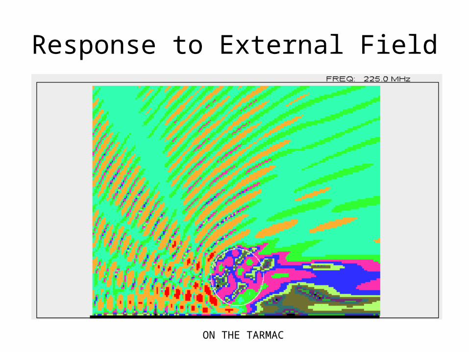
Response to External Field
ON THE TARMAC

Radiation Hazards
• Personnel (RADHAZ)
• Fuel (HERF)
• Ordinance (HERO)

Hazard to Personnel
• 10 W/m2 maximum averaged over a 6 minute period
• Corresponds to 61.4 Vrms/m

Flight Deck Hazard

E-Field Map

USS Forrestal

USS Forrestal

USS Forrestal
162 SAILORS PERISHED

Electromagnetic Environmental Effects
• Safety of flight
• Radiation Hazards
• Cosite interference
E3
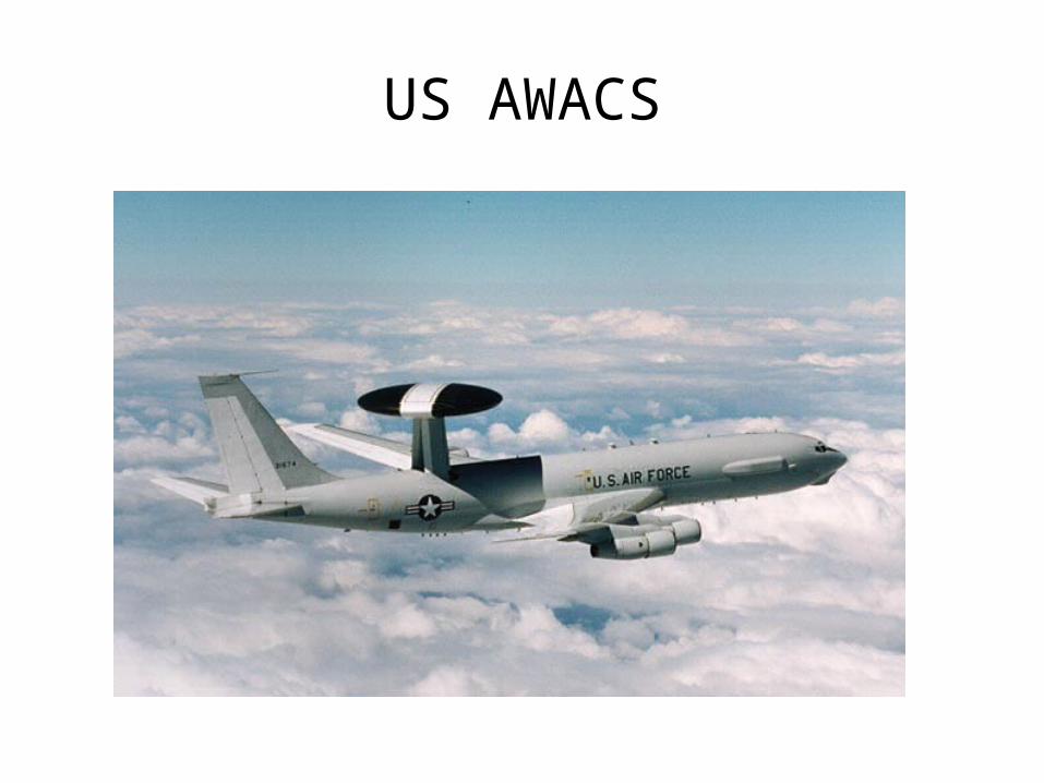
US AWACS

Co-Site Interference Analysis
Tx
Rx
H
H
Output PowerHarmonicsSpurious OutputsSignal Spectrum
Sensitivity
Image
Subharmonics
OBRTRR
Intermods
CouplingPath LossReflectionDiffraction
GainPattern
FiltersMulticouplers
Isolators
Broadband Noise
Tuning Range
Tuning Range
IF Feedthrough
Passband Shape
Cable Loss
Polarization SIR

A Gigantic Spreadsheet Problem
• NTx = number of transmitters
• NRx = number of receivers
• Nb = number transceivers
RxTxb
bRxTxnscombinatio NNN
NNNN
22
SINGLE-TONE ANALYSIS

A Gigantic Spreadsheet Problem
• NTx = number of transmitters (8)
• NRx = number of receivers (16)
• Nb = number transceivers (12)
RxTxb
bRxTxnscombinatio NNN
NNNN
22 (548)
SINGLE-TONE ANALYSIS
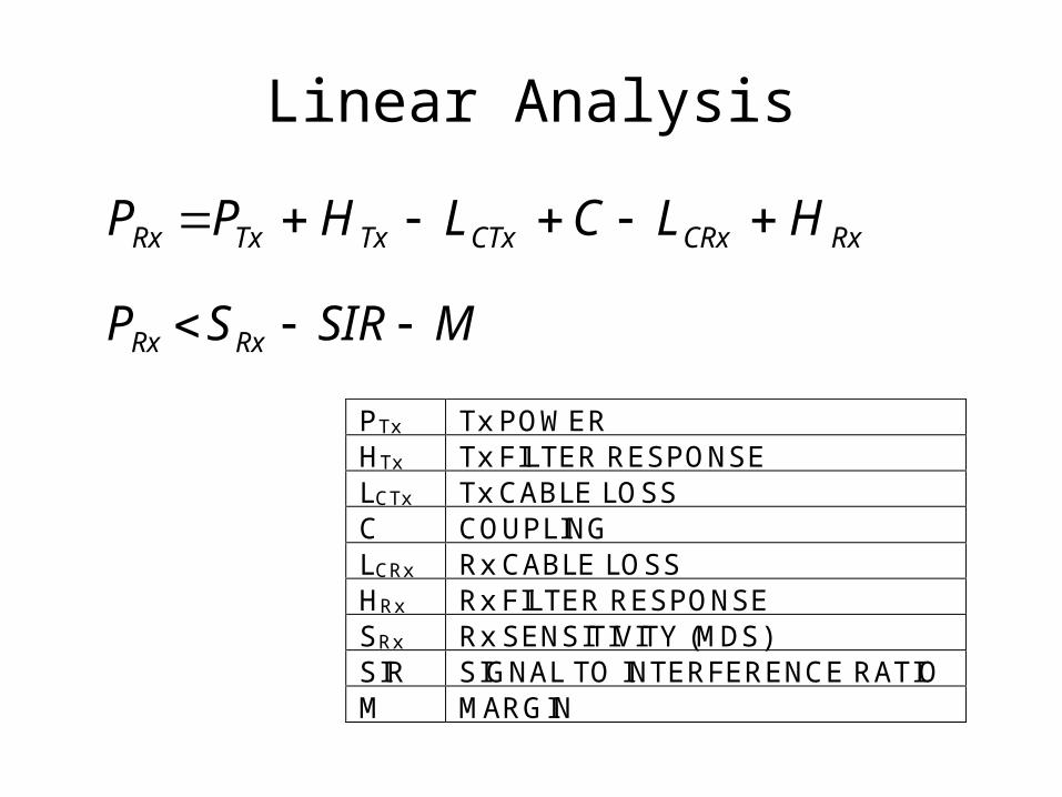
Linear Analysis
MSIRSP RxRx
RxCRxCTxTxTxRx HLCLHPP
PTx Tx POWER HTx Tx FILTER RESPONSE LCTx Tx CABLE LOSS C COUPLING LCRx Rx CABLE LOSS HRx Rx FILTER RESPONSE SRx Rx SENSITIVITY (MDS) SIR SIGNAL TO INTERFERENCE RATIO M MARGIN

Friis Equation
FAR-FIELD
C = COUPLING IN dB
R = SEPARATION DISTANCE = WAVELENGTH
G = ANTENNA GAIN
POLRxTxt
r LGGRP
PC
4log20 10
L = CROSS-POLARIZATION LOSSPOL

Antennas
• Antenna gain is directional
1010 2020
EXAMPLE ANTENNA PATTERN

Field from Isotropic Source
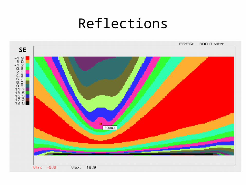
Reflections
SOURCE
SE
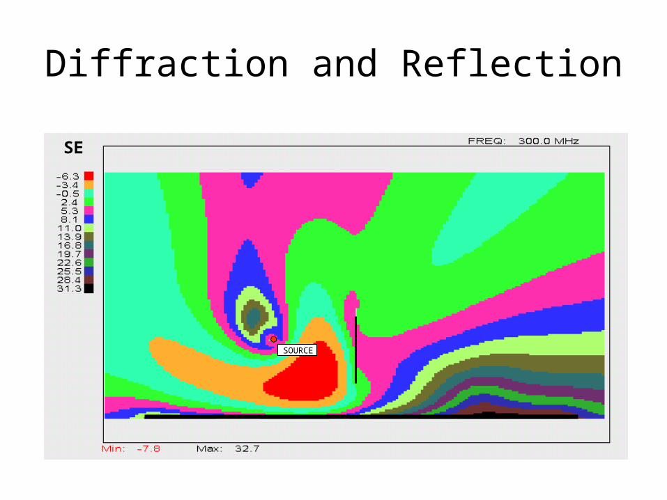
Diffraction and Reflection
SOURCE
SE

Modified Friis Equation
FAR-FIELD
C = COUPLING IN dB
R = SEPARATION DISTANCE = WAVELENGTH
G = ANTENNA GAIN
L = CROSS-POLARIZATION LOSSPOL
SE = SHIELDING EFFECTIVENESS
SELGGRP
PC POLRxTx
t
r
4log20 10

Nonlinear Effects
• Harmonic distortion
• Intermodulation distortion
• Gain Compression

Harmonic Distortion
• All transmitters generate harmonics.
• Harmonics can also be generated from a single tone applied to the receiver input circuitry.
f0 2f0 3f0 4f0

Intermodulation Distortion (IMD)
• Two transmitters, one receiver
f = f1-f2
FREQUENCY
f 1 f 2
2f -
f1
2
2f -
f2
1
3f -
2f1
2
4f -
3f1
2
3f -
2f2
1
4f -
3f2
1
Weierstrass Approximation Theorem

Third-Order IMD Example
Rx
Tx 1
Tx 2
f = 280 MHz
f = 284 MHz
f = 288 MHz
f = 276 MHzOR

Two-Tone Combinations
• NTx = number of transmitters
• NRx = number of receivers
• Nb = number transceivers
bTxbb
TxbRx
Txbnscombinatio NNNN
NNN
NNN 1
233
2

Two-Tone Combinations
• NTx = number of transmitters (8)
• NRx = number of receivers (16)
• Nb = number transceivers (12)
bTxbb
TxbRx
Txbnscombinatio NNNN
NNN
NNN 1
233
2
(5092)

Re-Radiated IMD
Tx1
Tx2
Rx1
Rx2

Cross Modulation
• Modulation from one signal is transferred onto another
Rx
Tx 1
Tx 2
MOST SEVERE ON AM SIGNALS

Cosite Interference Mitigation Options
• Coupling reduction• Filtering• Tuning rules• Blanking• Statistical Characterization• Active cancellation

Coupling Reduction
• Separation increase• Absorber• Cross polarization
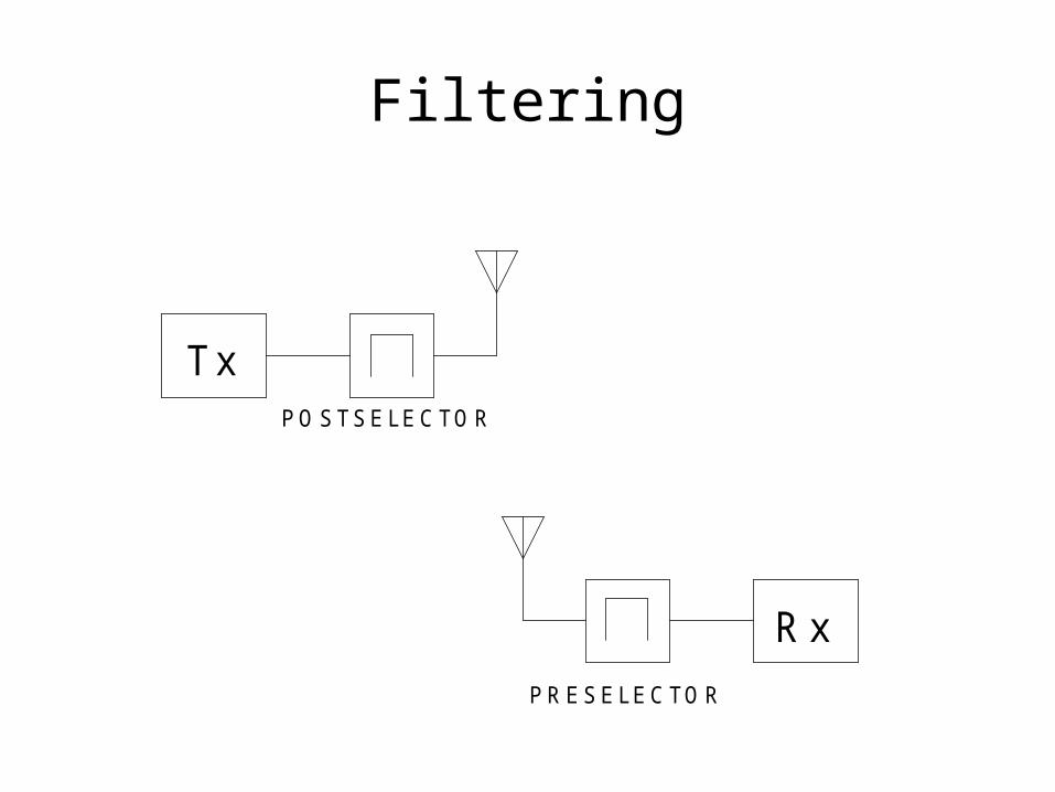
Filtering
TxPOSTSELECTOR
RxPRESELECTOR

Active Cancellation
Tx
Rx
COUPLER
AMPLITUDE &PHASE ADJUST
+

Accuracy Required
150 160 170 180 190 200 210-1
-0.8
-0.6
-0.4
-0.2
0
0.2
0.4
0.6
0.8
1
PHASE IN DEGREES
AM
PLI
TU
DE
IN
dB
-10
-15 -10 -15 -20
-25
-30
-40
CONTOURS OFCANCELLATION
IN dB

Summary
• E3 analysis is a significant portion of modern aircraft development.
• Interference from both internal and external sources must be considered for safety of flight.
• A thorough cosite interference analysis requires the evaluation of a large number of combinations.