Conover Dave Istec2008
19
1 ANSYS, Inc. Proprietary Verification and Validation of FEA Simulations Verification and Validation of FEA Simulations Dave Conover Chief Technologist Mechanical Business Unit ANSYS, Inc. Integration of Simulation Technology into the Engineering Curriculum Cornell University July 25-26, 2008
-
Upload
janaaidaas1996 -
Category
Documents
-
view
11 -
download
1
description
Importance of Validation and Verification Process in FEA
Transcript of Conover Dave Istec2008
1 ANSYS, Inc. Proprietary
Verification and Validation of FEA Simulations Verification and Validation of FEA Simulations
Dave ConoverChief TechnologistMechanical Business UnitANSYS, Inc.
Integration of Simulation Technology into the Engineering Curriculum Cornell UniversityJuly 25-26, 2008
2
What I’ve Learned About Engineering
• You only learn 1/3 of what you need to know in school
• It’s not what you know, it’s what you can know
• Critical thinking and problem solving are crucial
• A good grounding in the basics and fundamentals will take you far
3
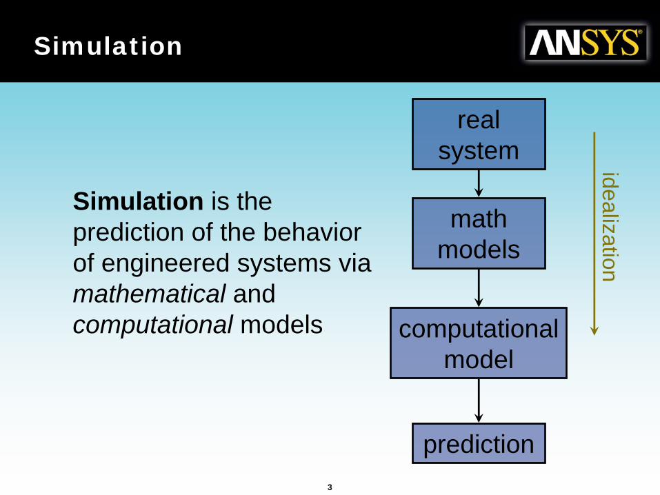
Simulation
Simulation is the prediction of the behavior of engineered systems via mathematical and computational models
real system
math models
computational model
prediction
idealization
4
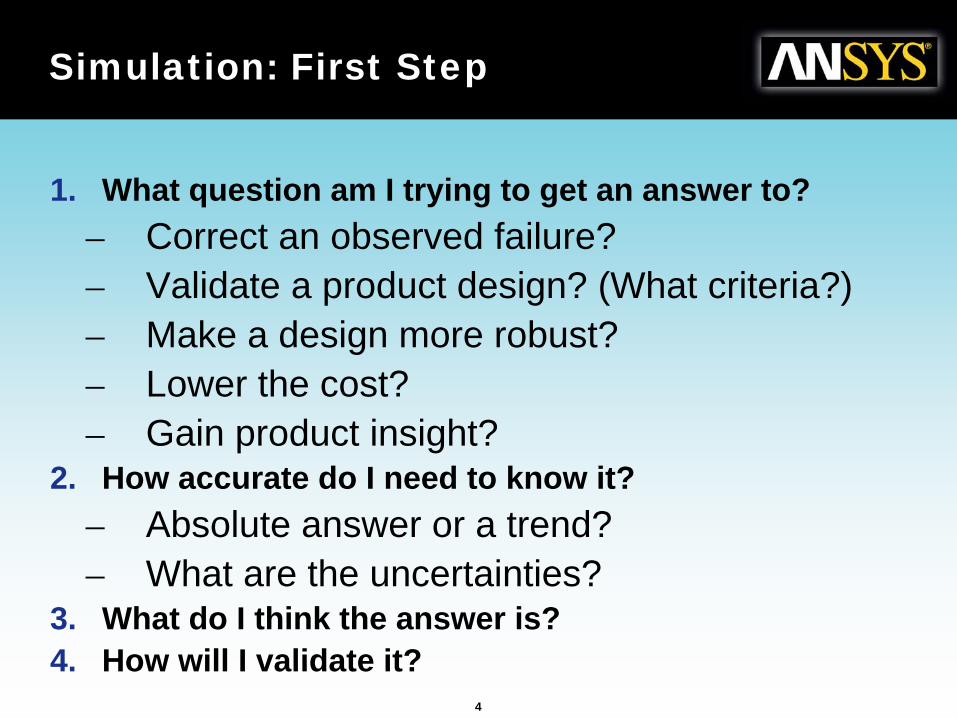
Simulation: First Step
1. What question am I trying to get an answer to?– Correct an observed failure?– Validate a product design? (What criteria?)– Make a design more robust?– Lower the cost?– Gain product insight?
2. How accurate do I need to know it?– Absolute answer or a trend?– What are the uncertainties?
3. What do I think the answer is?4. How will I validate it?
5
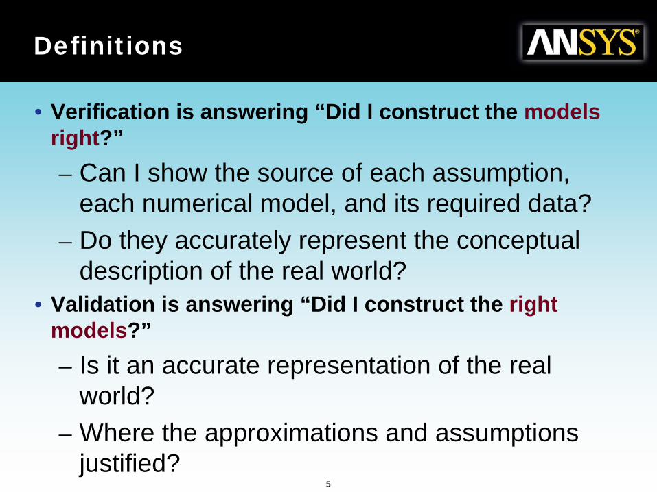
Definitions
• Verification is answering “Did I construct the models right?”– Can I show the source of each assumption,
each numerical model, and its required data?– Do they accurately represent the conceptual
description of the real world?• Validation is answering “Did I construct the right
models?”– Is it an accurate representation of the real
world?– Where the approximations and assumptions
justified?
6
Validation
“You cannot really validate a simulation,
only invalidate it”
7
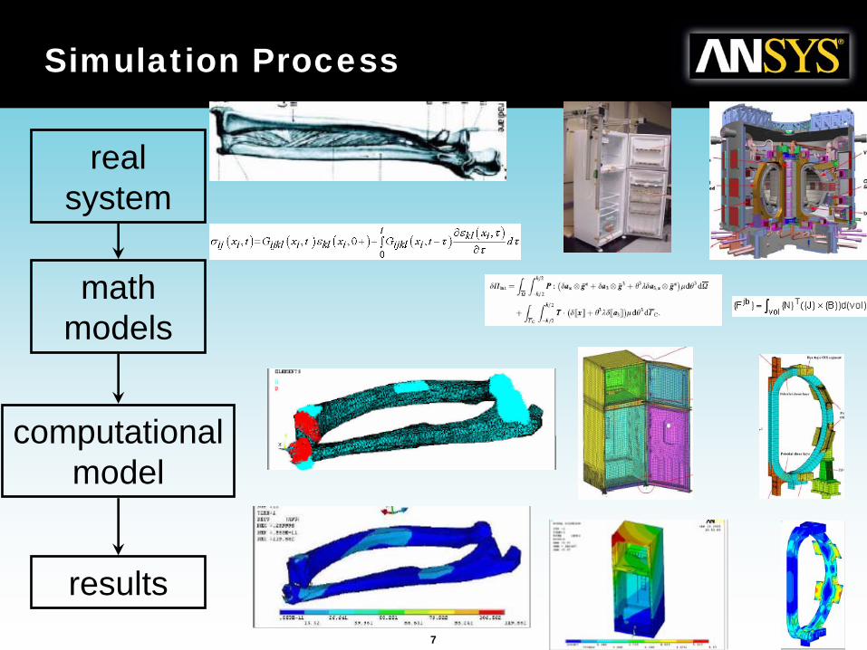
Simulation Process
real system
math models
computational model
results
8
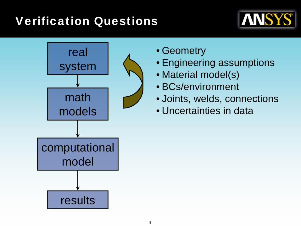
Verification Questions
real system
math models
computational model
results
• Geometry• Engineering assumptions• Material model(s)• BCs/environment• Joints, welds, connections• Uncertainties in data
9
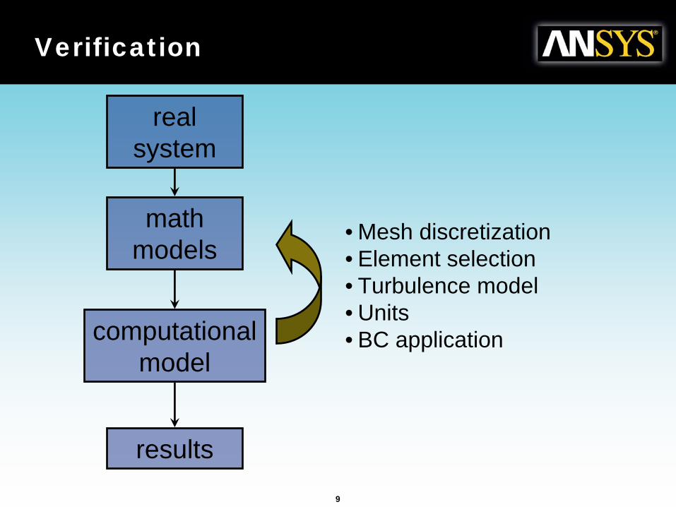
Verification
real system
math models
computational model
results
• Mesh discretization• Element selection• Turbulence model• Units• BC application
10
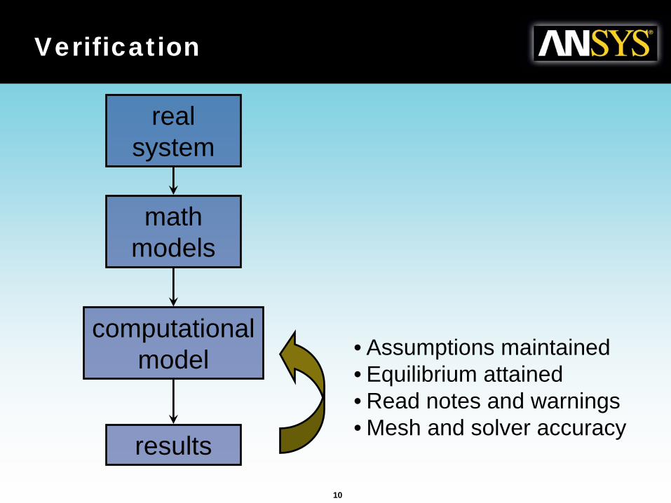
Verification
real system
math models
computational model
results
• Assumptions maintained• Equilibrium attained• Read notes and warnings• Mesh and solver accuracy
11
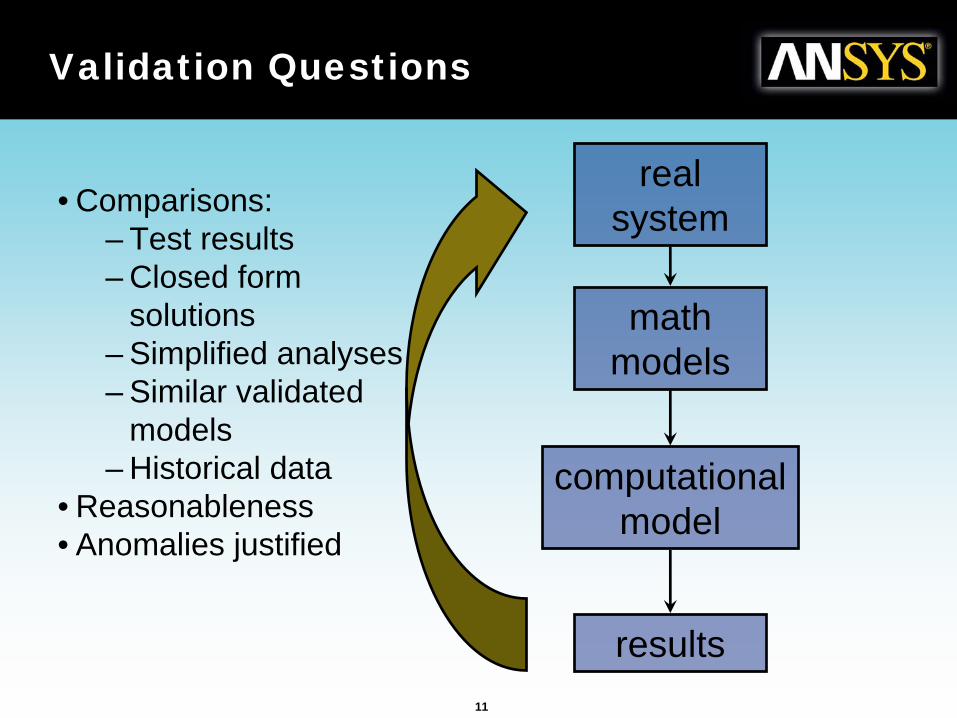
Validation Questions
real system
math models
computational model
results
• Comparisons:– Test results– Closed form
solutions– Simplified analyses– Similar validated
models– Historical data
• Reasonableness• Anomalies justified
12
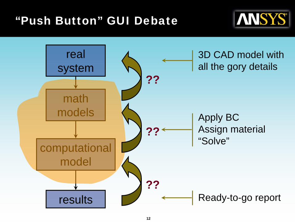
“Push Button” GUI Debate
real system
math models
computational model
results
3D CAD model with all the gory details
Apply BCAssign material“Solve”
Ready-to-go report??
??
??
13
Engineering Education
• Thorough understanding of engineering principles
• Ability to think critically– Analysis, synthesis and evaluation
• Validation process as part of class work– Formal part of reports and projects– Peer project reviews– Test and simulation done together
14
Industry Examples†
† Taken from past ANSYS International Conference proceedings
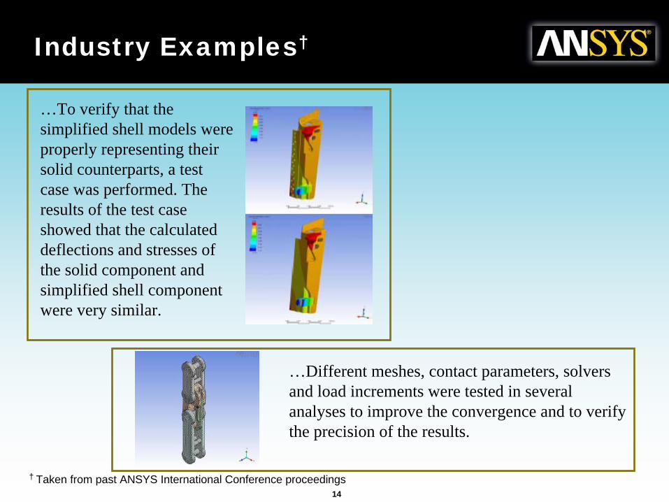
…To verify that the simplified shell models were properly representing their solid counterparts, a test case was performed. The results of the test case showed that the calculated deflections and stresses of the solid component and simplified shell component were very similar.
…Different meshes, contact parameters, solvers and load increments were tested in several analyses to improve the convergence and to verify the precision of the results.
15
Industry Examples
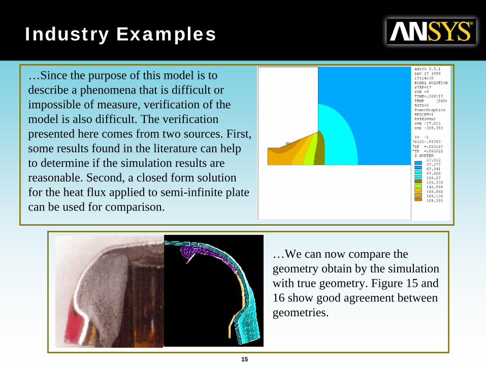
…Since the purpose of this model is to describe a phenomena that is difficult or impossible of measure, verification of the model is also difficult. The verification presented here comes from two sources. First, some results found in the literature can help to determine if the simulation results are reasonable. Second, a closed form solution for the heat flux applied to semi-infinite plate can be used for comparison.
…We can now compare the geometry obtain by the simulation with true geometry. Figure 15 and 16 show good agreement between geometries.
16
Industry Examples
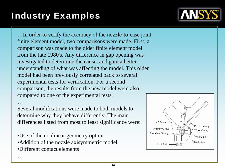
…In order to verify the accuracy of the nozzle-to-case joint finite element model, two comparisons were made. First, a comparison was made to the older finite element model from the late 1980's. Any difference in gap opening was investigated to determine the cause, and gain a better understanding of what was affecting the model. This older model had been previously correlated back to several experimental tests for verification. For a second comparison, the results from the new model were also compared to one of the experimental tests.…Several modifications were made to both models to determine why they behave differently. The main differences listed from most to least significance were:
•Use of the nonlinear geometry option•Addition of the nozzle axisymmetric model•Different contact elements…
17
Industry Examples
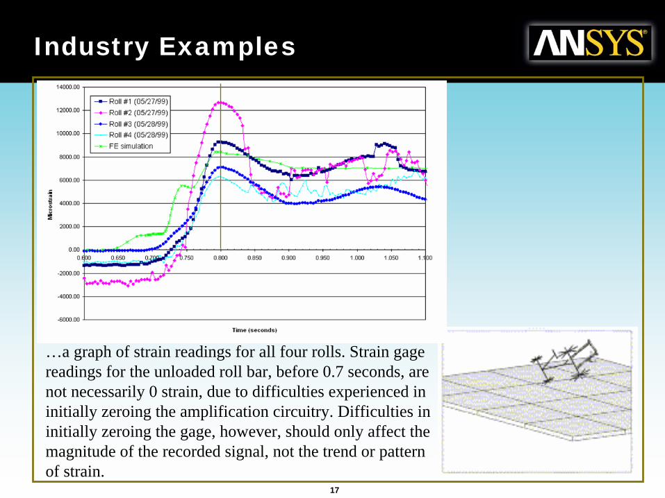
…
…a graph of strain readings for all four rolls. Strain gage readings for the unloaded roll bar, before 0.7 seconds, are not necessarily 0 strain, due to difficulties experienced in initially zeroing the amplification circuitry. Difficulties in initially zeroing the gage, however, should only affect the magnitude of the recorded signal, not the trend or pattern of strain.
18
Industry Examples
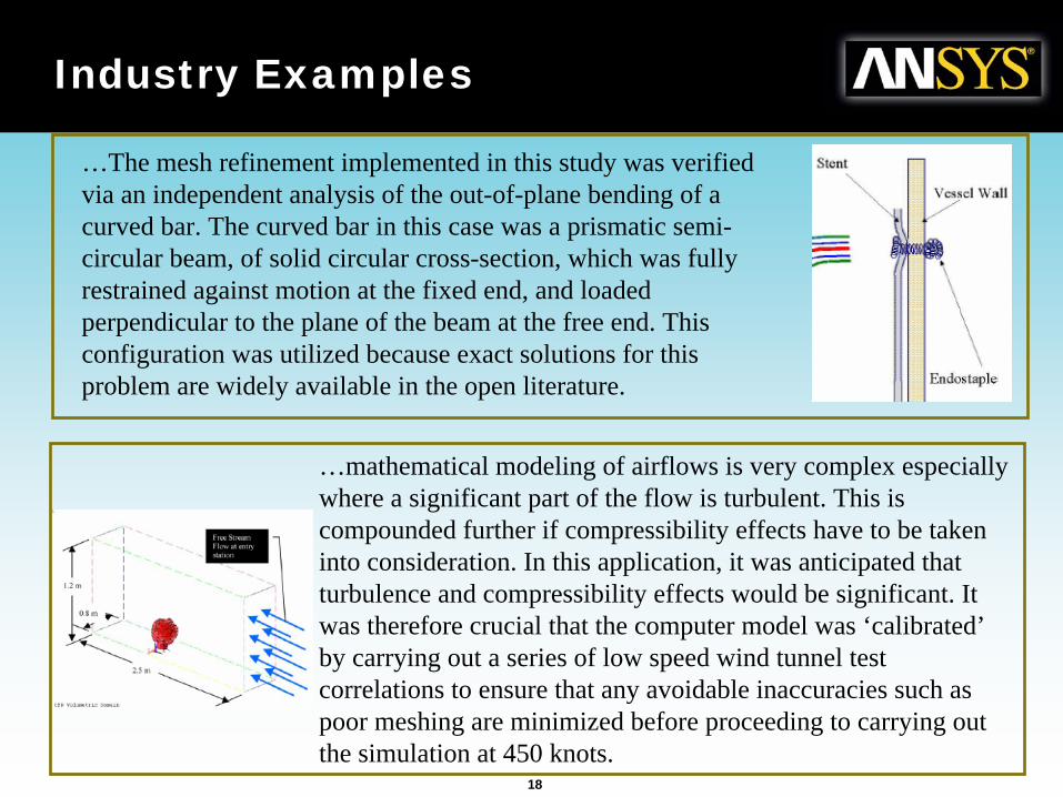
…The mesh refinement implemented in this study was verified via an independent analysis of the out-of-plane bending of a curved bar. The curved bar in this case was a prismatic semi- circular beam, of solid circular cross-section, which was fully restrained against motion at the fixed end, and loaded perpendicular to the plane of the beam at the free end. This configuration was utilized because exact solutions for this problem are widely available in the open literature.
…mathematical modeling of airflows is very complex especially where a significant part of the flow is turbulent. This is compounded further if compressibility effects have to be taken into consideration. In this application, it was anticipated that turbulence and compressibility effects would be significant. It was therefore crucial that the computer model was ‘calibrated’ by carrying out a series of low speed wind tunnel test correlations to ensure that any avoidable inaccuracies such as poor meshing are minimized before proceeding to carrying out the simulation at 450 knots.
19
References
• NAFEMS http://www.nafems.org/• VV&A Recommended Practices Guide (DoD)
http://vva.dmso.mil/• Simulation-Based Engineering Science -
Revolutionizing Engineering Science through Simulation, A Report of the National Science Foundation Blue Ribbon Panel http://www.ticam.utexas.edu/events/SBES_Final_Rep ort.pdf
• Building Better Products With Finite Element Analysis, Adams, V., Askenazi, A., (1998)
• www.xansys.org, an ANSYS email list server