CONOCOPHILLIPS GLOBAL NVE GREENLAND LTD...
27
CONOCOPHILLIPS GLOBAL NVE GREENLAND LTD 2012 PROGRAM BLOCK 2 (QAMUT) 2D SEISMIC SURVEY Supplemental Filing Change of Fleet for submission to: Bureau of Minerals and Petroleum Imaneq 29 Post-box 930 3900 Nuuk Greenland Distribution: BMP: 1 Electronic Copy and 1 Hard Copy ConocoPhillips: 1 Electronic Copy DONG E&P 1 Electronic Copy Nunaoil 1 Electronic Copy 20 June 2012 1113340084 Final
-
Upload
truongkiet -
Category
Documents
-
view
233 -
download
0
Transcript of CONOCOPHILLIPS GLOBAL NVE GREENLAND LTD...

CONOCOPHILLIPS GLOBAL NVE GREENLAND LTD
2012 PROGRAM BLOCK 2 (QAMUT)
2D SEISMIC SURVEY
Supplemental Filing Change of Fleet
for submission to:
Bureau of Minerals and Petroleum Imaneq 29
Post-box 930 3900 Nuuk Greenland
Distribution: BMP: 1 Electronic Copy and 1 Hard Copy ConocoPhillips: 1 Electronic Copy DONG E&P 1 Electronic Copy Nunaoil 1 Electronic Copy
20 June 2012 1113340084 Final

ConocoPhillips Global NVE Greenland LTD. - i - Final Supplemental Filing 20 June 2012
TABLE OF CONTENTS
SECTION
1 Introduction .....................................................................................................................
PAGE
1
2 Vessel Details and Operations ........................................................................................ 2
3 Change of Fleet from an Environmental Perspective ....................................................... 3 3.1 Effects of Airborne Emissions from Project Vessels .............................................................. 3 3.2 Effects of Discharges from Project Vessels ........................................................................... 4 3.3 Effects of Underwater Sound on the Marine Environment ..................................................... 4 3.4 Effects of Vessel Traffic ......................................................................................................... 5 3.5 Effects of Vessel Lighting ....................................................................................................... 5 3.6 Effects of Introduced Species from Ballast Water Exchange ................................................ 5 3.7 Effects of Unplanned Events and Accidental Spills ............................................................... 5
4 Appendices ..................................................................................................................... 6
LIST OF TABLES
Table 3.1-1: Comparison of Total Fuel Consumption involving Change of Fleet ................................... 3 Table 3.1-2: Comparison of Air Emissions involving Change of Fleet .................................................... 3 Table 3.1-3: Comparison of Greenhouse Gas Emissions involving Change of Fleet............................. 4
ConocoPhillips Global NVE Greenland LTD. - 1 - Final Supplemental Filing 20 June 2012
1 Introduction
This document is a Supplemental Filing related to the Final Environmental Impact Assessment (EIA) of a 2D-seimic survey in Block 2 (Qamut) that was submitted to the Bureau of Minerals and Petroleum (BMP) on 14 June 2012 by ConocoPhillips Global NVE Greenland Ltd., DONG E&P Grønland A/S and Nunaoil A/S (referred to collectively as “ConocoPhillips”). This seismic survey would take place from early August to mid-September 2012, with the option of extending to 1 October 2012 if ice conditions, weather conditions, sea state or other factors delay the program.
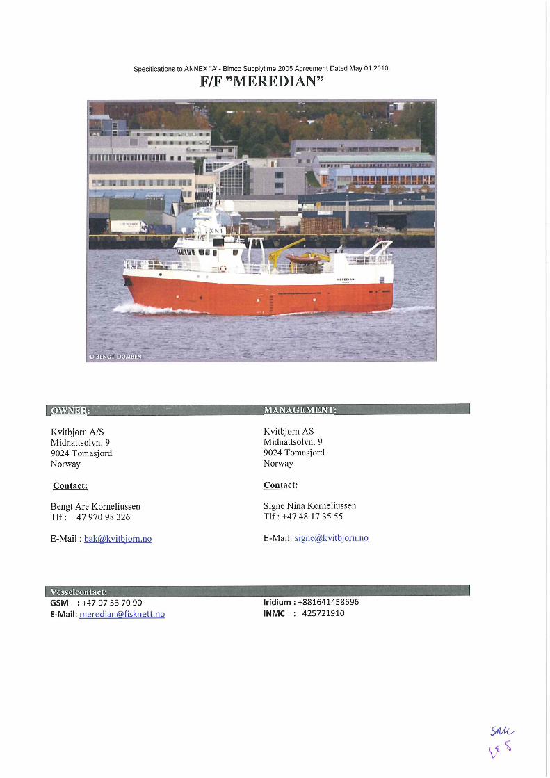
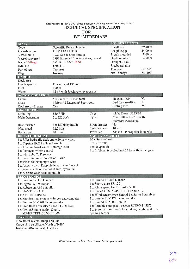
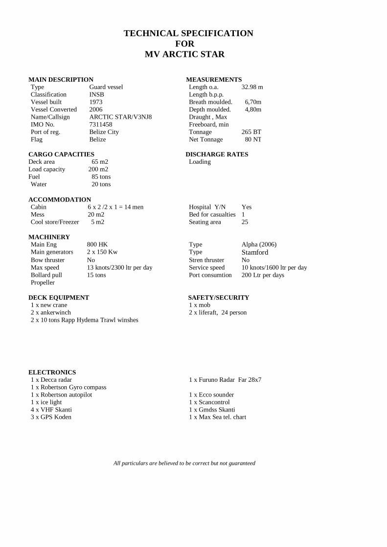
It was noted in Section 3.1 of the Final EIA that three vessels had been chartered by ConocoPhillips for the seismic survey in Qamut Block, including: one ice-class seismic survey ship; one ice-class chase vessel; and one support and re-supply vessel. The CGGVeritas M/V Princess was identified as the ship that would be performing the 2D-seismic survey (including collection of marine gravity and magnetic data). The chase ship and support/re-supply ship would be the M/V Thor Supplier and the M/V Thor Beamer, respectively. This fleet was part of the basis for environmental assessment in the Preliminary EIA. In early June 2012, it was necessary for ConocoPhillips to change these ships. They have been replaced by equivalent vessels, including the Artemis Angler as the seismic ship, F/F Meredian as the chase ship, and MV Arctic Star as the support/re-supply ship (which may act as a second chase ship). ConocoPhillips mentioned that the airgun array and single streamer that will be deployed by the Artemis Angler would be identical to the airgun array and single streamer that would have been deployed by the Princess. It was also noted that CGGVeritas would continue to be the seismic contractor for the survey.
ConocoPhillips decided that the Final EIA would not be altered to reflect this change in the fleet of ships, or “Change of Fleet”, since it was an operations planning adjustment that is not uncommon during seismic surveys when release of a ship, or ships, from a previous charter has been delayed, or when any or all of the proposed ships are not available for other reasons. It was indicated, at the time, that the Change of Fleet was not regarded as material or significant from an environmental assessment perspective, and that it would be addressed by ConocoPhillips during the “Application Package” process for the 2012 program, or in a Supplemental Filing to BMP. Finally, in light of this situation, it was explained that mention of the Princess, Thor Supplier or Thor Beamer in the rest of Section 3, or in other sections of the Final EIA, would be left as is.
The Change of Fleet is discussed in this report. The replacement fleet is compared to the original fleet from an environmental assessment point of view, based on impact significance ratings for specific potential effects after mitigation measures have been applied at block or licence level. ConocoPhillips does not believe it is necessary to extend the comparison to cumulative effects of underwater sound at regional scale, since the airgun array, in particular, will not be changed from the airgun array that was modelled and assessed in the Final EIA. It will be configured the same way, and operated that way along the same number of sail lines, during the survey. The total number of line-kilometres will be identical.

ConocoPhillips Global NVE Greenland LTD. - 2 - Final Supplemental Filing 20 June 2012
2 Vessel Details and Operations
The vessels comprising the replacement fleet are described in Appendix A (seismic survey ship) and Appendix B (chase ships). A small amount of additional information is provided below.
The airgun array deployed by the Artemis Angler will be identical to the array that would have been deployed by the Princess, as noted above. The other active sound sources on the Artemis Angler will be equivalent to those on the Princess, including: a ship’s own echosounder for safety of navigation purposes (Furuno FE 680), and a dedicated single-beam system for accurate depth measurement during the seismic survey (Simrad EA 500).
Collection of marine gravity and magnetic data by the seismic survey ship will not be altered by the Change of Fleet. This information is obtained with passive measurement systems that do not emit sound or energy.
The passive acoustic monitoring (PAM) system on the Artemis Angler will be the same as the system that would have been used on the Princess. The four hydrophones will be deployed aft of the ship in a similar manner, and the system will be operated the same way.
The classification of Artemis Angler, according to CGGVeritas, is DNV +1A1 ICE C (hull constructed to ICE 1B specification; rudder, propeller and blisters are ICE C), compared to DNV 1A1 ICE 1A for MV Princess. The Angler has a lower ice class, but ConocoPhillips believes this level of ice strengthening will be sufficient for “open water” or “ice free” operations in Qamut Block during the survey period. The ice class of the two chase ships is equal or higher. The Ice Management Plan for the survey is not altered by the Change of Fleet. It will continue to be focused on ice avoidance.
The Artemis Angler is equipped with a helipad, which likely has implications for medical evacuations, and transfer of personnel for other reasons (death or serious illness of family members, for example). The Princess did not have a helipad. The Emergency Response Plan for the seismic survey will be modified accordingly.

ConocoPhillips Global NVE Greenland LTD. - 3 - Final Supplemental Filing 20 June 2012
3 Change of Fleet from an Environmental Perspective
3.1 Effects of Airborne Emissions from Project Vessels
Table 3.1-1 presents the total fuel consumption for the new fleet of ships compared to fleet of ships assessed in the Final EIA Report submitted to BMP on 14 June 2012. This table, in part, reflects Table 6.1-1 on page 33 in the Final EIA Report. All assumptions for calculating fuel consumption related to the original fleet and the replacement fleet are the same.
Table 3.1-1: Comparison of Total Fuel Consumption involving Change of Fleet
Vessel Activity
Original Fleet Assessed in Final EIA New Vessel Fleet Vessel Name
Daily Fuel Consumption
(m3)
Total Fuel Consumption
(m3)
Vessel Name
Daily Fuel Consumption
(m3)
Total Fuel Consumption
(m3) Seismic Survey (60 days)
MV Princess
14 840 Artemis Angler
12 720
MV Thor Beamer
1.1 66 MV Arctic Star
1 60
MV Thor Supplier
5 300 Meredian 1 60
Mobilization / demobilization between Nuuk and survey Block (one 5-day round trip per vessel)
MV Princess
15 75 Artemis Angler
18 90
MV Thor Beamer
6.5 32.5 MV Arctic Star
2 10
MV Thor Supplier
21 105 Meredian 2 10
Fuel / resupply trip to Nuuk (one 5-day round trip per vessel)
MV Princess
15 75 Artemis Angler
18 90
MV Thor Beamer
6.5 32.5 MV Arctic Star
2 10
MV Thor Supplier
21 105 Meredian 2 10
Total Fuel Consumption 1,631 1,060 Table 3.1-2 presents the total estimated air emissions of the replacement fleet compared to the fleet assessed in the Final EIA Report submitted to BMP on 14 June 2012. This table, in part, reflects Table 6.1-2 on page 33 in the Final EIA Report.
Table 3.1-2: Comparison of Air Emissions involving Change of Fleet
Emission Parameter
Original Fleet Assessed in Final EIA New Vessel Fleet Emission factor
(kg emitted / tonne fuel consumed)
Total emission during seismic
program (tonnes)
Emission factor (kg emitted / tonne
fuel consumed)
Total emission during seismic
program (tonnes) PM 1.2 1.92 1.2 1.25 SOx 30.0 48.00 30.0 31.20 NOx 87.0 139.20 87.0 90.47 VOC 2.4 3.84 2.4 2.50 CO 7.4 11.84 7.4 7.69
ConocoPhillips Global NVE Greenland LTD. - 4 - Final Supplemental Filing 20 June 2012
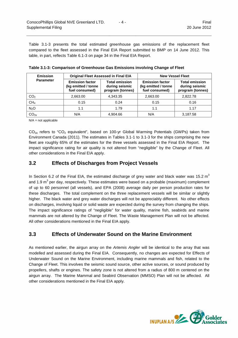
Table 3.1-3 presents the total estimated greenhouse gas emissions of the replacement fleet compared to the fleet assessed in the Final EIA Report submitted to BMP on 14 June 2012. This table, in part, reflects Table 6.1-3 on page 34 in the Final EIA Report.
Table 3.1-3: Comparison of Greenhouse Gas Emissions involving Change of Fleet
Emission Parameter
Original Fleet Assessed in Final EIA New Vessel Fleet Emission factor
(kg emitted / tonne fuel consumed)
Total emission during seismic
program (tonnes)
Emission factor (kg emitted / tonne
fuel consumed)
Total emission during seismic
program (tonnes) CO2 2,663.00 4,343.35 2,663.00 2,822.78 CH4 0.15 0.24 0.15 0.16 N2O 1.1 1.79 1.1 1.17 CO2e N/A 4,904.66 N/A 3,187.58 N/A = not applicable
CO2e refers to “CO2 equivalent”, based on 100-yr Global Warming Potentials (GWPs) taken from Environment Canada (2011). The estimates in Tables 3.1-1 to 3.1-3 for the ships comprising the new fleet are roughly 65% of the estimates for the three vessels assessed in the Final EIA Report. The impact significance rating for air quality is not altered from “negligible” by the Change of Fleet. All other considerations in the Final EIA apply.
3.2 Effects of Discharges from Project Vessels
In Section 6.2 of the Final EIA, the estimated discharge of grey water and black water was 15.2 m3 and 1.9 m3 per day, respectively. These estimates were based on a probable (maximum) complement of up to 60 personnel (all vessels), and EPA (2008) average daily per person production rates for these discharges. The total complement on the three replacement vessels will be similar or slightly higher. The black water and grey water discharges will not be appreciably different. No other effects on discharges, involving liquid or solid waste are expected during the survey from changing the ships. The impact significance ratings of “negligible” for water quality, marine fish, seabirds and marine mammals are not altered by the Change of Fleet. The Waste Management Plan will not be affected. All other considerations mentioned in the Final EIA apply.
3.3 Effects of Underwater Sound on the Marine Environment
As mentioned earlier, the airgun array on the Artemis Angler will be identical to the array that was modelled and assessed during the Final EIA. Consequently, no changes are expected for Effects of Underwater Sound on the Marine Environment, including marine mammals and fish, related to the Change of Fleet. This involves the seismic sound source, other active sources, or sound produced by propellers, shafts or engines. The safety zone is not altered from a radius of 800 m centered on the airgun array. The Marine Mammal and Seabird Observation (MMSO) Plan will not be affected. All other considerations mentioned in the Final EIA apply.
ConocoPhillips Global NVE Greenland LTD. - 5 - Final Supplemental Filing 20 June 2012
3.4 Effects of Vessel Traffic
There are no expected changes for Effects of Vessel Traffic, including ship strikes with marine mammals, since the number of ships, transit speed to and from Qamut Block and speed maintained during the survey are not changed from the original fleet. ConocoPhillips believes that all three replacement vessels will be operated in the same competent and professional manner, based on “best practice at sea” and compliance with applicable CGGVeritas standards.
3.5 Effects of Vessel Lighting
No change expected for Effects of Vessel Lighting. The survey period is not altered by the Change of Fleet, and consequently, the estimates for length of daylight/twilight in Qamut Block (since lighting will be required during periods of darkness or deep twilight only) in the Final EIA are not affected.
3.6 Effects of Introduced Species from Ballast Water Exchange
No change is expected for for Effects of Introduced Species from Ballast Water Exchange involving the Change of Fleet. The Ballast Water Management Plan will need to be modified, however, since it is ship-specific for Artemis Angler and the two chase vessels.
3.7 Effects of Unplanned Events and Accidental Spills
In Section 6.7 of the Final EIA, the scenario assessed for a major unplanned event was a 300 m3 accidental spill of marine diesel fuel (MDF) due to collision of MV Princess with another ship, or with an iceberg, that led to rupture of multiple tanks. This number was one-third to one-half of total tank capacity (692 m3, or “full fuel”) for the Princess, which was regarded as a realistic operational situation for assessment purposes. The total tank capacity for Artemis Angler is 800 m3. The corresponding value for a major accidental spill would be 350 m3. ConocoPhillips does not believe an increase of 50 m3 is significant for this scenario. The impact significant ratings of “low” for seabirds and marine mammals, and “negligible” for sediment quality, water quality, marine fish and subsistence hunting/fishing, are not altered by the Change of Fleet. No differences are expected for minor unplanned events. Procedures onboard the Artemis Angler will conform to applicable CGGVeritas standards. All other considerations mentioned in the Final EIA apply.

ConocoPhillips Global NVE Greenland LTD. - 6 - Final Supplemental Filing 20 June 2012
4 Appendices
APPENDIX A: VESSEL PARTICULARS FOR ARTEMIS ANGLER

Artemis Angler
Technical Specifications
Vessel Details Vessel Name Artemis Angler Owner Artemis Angler AS - Maritime ManagementFlag NIS (Norway) Port Of Registry Bergen Built / Rebuilt 1998/2008 Class DNV +1A1 – Ice C – E.O – Dynpos AUTR – Helidk. S Class ID N° 19261 Call Sign LAGU7 IMO Official Number 9181467 Length 66 m Beam 14 / 16.5 m Min Draught 7.2 m Max Draught 7.8 m Dead Weight / Net Tonnage 2350/924 Gross Registered Tonnage 3080 tons Cruising Speed 12 knots Fuel Capacity 800 m3 full tanks Endurance Approx 40 days Fuel Consumption 17 m3 ( Production) Fresh Water 74.5 m3 Main Engines Caterpillar 3612TA 3800 BkW 2 900 rpm Bow Thrusters 1 X Brunvoll 1000 kW Azimuth Thruster 1 X Aquamaster UL2001 1500Kw @ 1800 RPM Stern Thruster 1 X Brunvoll 1000kW Class Approved Maintenance System TM Master
_________________________________________________________________________
_____________________________________________________________________ Page 2 of 13
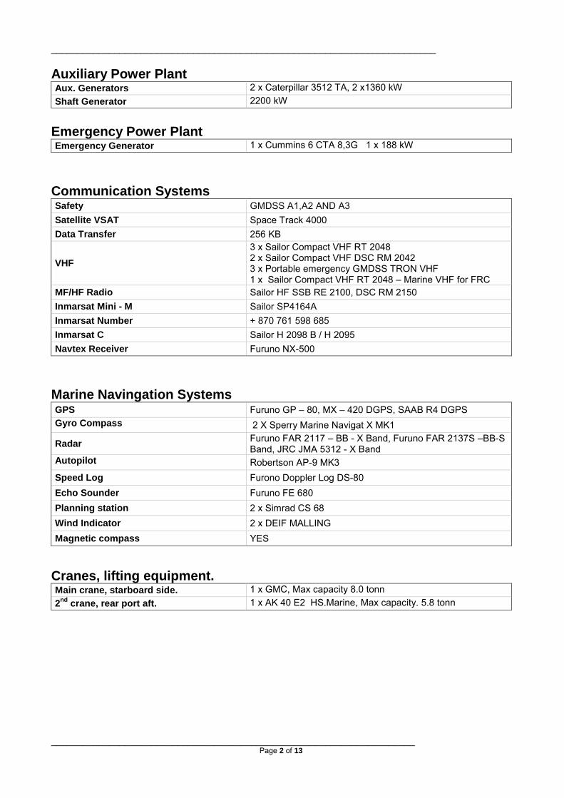
Auxiliary Power Plant Aux. Generators 2 x Caterpillar 3512 TA, 2 x1360 kW Shaft Generator 2200 kW
Emergency Power Plant Emergency Generator 1 x Cummins 6 CTA 8,3G 1 x 188 kW
Communication Systems Safety GMDSS A1,A2 AND A3 Satellite VSAT Space Track 4000 Data Transfer 256 KB
VHF 3 x Sailor Compact VHF RT 2048 2 x Sailor Compact VHF DSC RM 2042 3 x Portable emergency GMDSS TRON VHF 1 x Sailor Compact VHF RT 2048 – Marine VHF for FRC
MF/HF Radio Sailor HF SSB RE 2100, DSC RM 2150 Inmarsat Mini - M Sailor SP4164A Inmarsat Number + 870 761 598 685 Inmarsat C Sailor H 2098 B / H 2095 Navtex Receiver Furuno NX-500
Marine Navingation Systems GPS Furuno GP – 80, MX – 420 DGPS, SAAB R4 DGPS Gyro Compass 2 X Sperry Marine Navigat X MK1
Radar Furuno FAR 2117 – BB - X Band, Furuno FAR 2137S –BB-S Band, JRC JMA 5312 - X Band
Autopilot Robertson AP-9 MK3 Speed Log Furono Doppler Log DS-80 Echo Sounder Furuno FE 680 Planning station 2 x Simrad CS 68 Wind Indicator 2 x DEIF MALLING Magnetic compass YES
Cranes, lifting equipment. Main crane, starboard side. 1 x GMC, Max capacity 8.0 tonn 2nd crane, rear port aft. 1 x AK 40 E2 HS.Marine, Max capacity. 5.8 tonn
_________________________________________________________________________
_____________________________________________________________________ Page 3 of 13
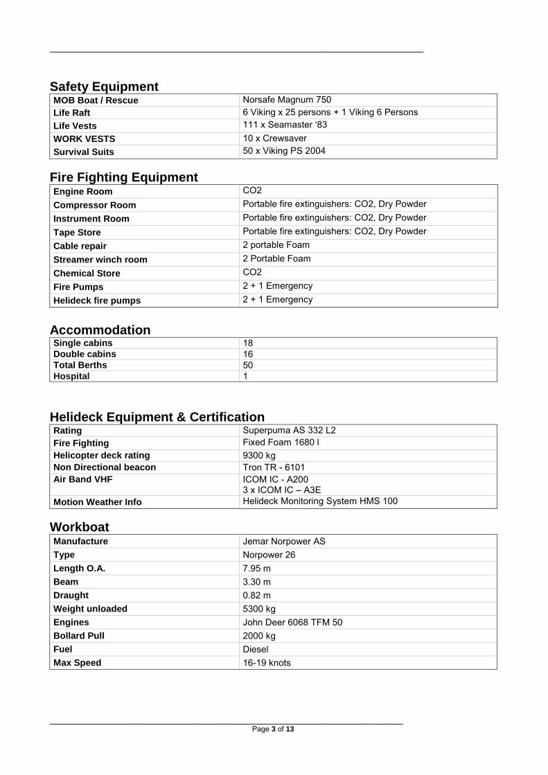
Safety Equipment MOB Boat / Rescue Norsafe Magnum 750 Life Raft 6 Viking x 25 persons + 1 Viking 6 Persons Life Vests 111 x Seamaster ‘83 WORK VESTS 10 x Crewsaver Survival Suits 50 x Viking PS 2004
Fire Fighting Equipment Engine Room CO2 Compressor Room Portable fire extinguishers: CO2, Dry Powder Instrument Room Portable fire extinguishers: CO2, Dry Powder Tape Store Portable fire extinguishers: CO2, Dry Powder Cable repair 2 portable Foam Streamer winch room 2 Portable Foam Chemical Store CO2 Fire Pumps 2 + 1 Emergency Helideck fire pumps 2 + 1 Emergency
Accommodation Single cabins 18 Double cabins 16 Total Berths 50 Hospital 1
Helideck Equipment & Certification Rating Superpuma AS 332 L2 Fire Fighting Fixed Foam 1680 l Helicopter deck rating 9300 kg Non Directional beacon Tron TR - 6101 Air Band VHF ICOM IC - A200
3 x ICOM IC – A3E Motion Weather Info Helideck Monitoring System HMS 100
Workboat Manufacture Jemar Norpower AS Type Norpower 26 Length O.A. 7.95 m Beam 3.30 m Draught 0.82 m Weight unloaded 5300 kg Engines John Deer 6068 TFM 50 Bollard Pull 2000 kg Fuel Diesel Max Speed 16-19 knots

_________________________________________________________________________
_____________________________________________________________________ Page 4 of 13
Survey Equipment Specifications Energy Source G Gun Description
The G-Gun has become an industry standard high pressure air source, with 40% fewer parts than the simplest available air gun on the market, making it extremely reliable and with 50 micro second standard deviation pulse repeatability, this makes the G- Guns performance excellent in a compact body.
Source Type G Gun Manufacturer Sercel Sodera Source Volume 2 x 4320 Cu.in 2 X 3 Sub-arrays / 2 X 100 barM (p-p) Operating Pressure 2000 psi Number of Strings 6 Guns per String 12 (6 Custers consisting of 2 Gun) Pressure Transducer 1 per string Depth Transducer 3 per string Near Field Hydrophones 1 per custer Near Field Phones 6 per array. Gun Depth Sensors 3 per array. Minimum Recycle Time ~ 7.0 seconds
Compresssors 3 x LMF 51s/138-207E each 1800 CFM@2000 psi electric driven
Deflectors Baro 44 Tow System Baro flexible gun floats.
Source Controller Gunlink 2000 Description
The GunLink 2000 gun control system provides onboard firing control and sensor timing monitoring of up to 256 standard guns and is capable of receiving hydrophone data from up to 512 near field phones. The analog circuitry allows each near field phone and firing sensor to be monitored continuously using a 24 bit A/D converter sampling at 0.1mS thus providing increased gun firing accuracy and auto-fire detection.
Gun Controller Type Gunlink 2000 Manufacturer Seamap Maximum Number of Guns 256 (Note 96 onboard) Timing Resolution 0.1 ms Fire Detect Window 120 ms Data Time Stamping All data time stamped to GPS time
Safety Features Key controlled remote and local system disable. Bleed resistors on each solenoid output dump charge at system disable. Interface to vessel’s MOB system.
Remote Displays Large format digital pressure displays to display umbilical pressures on the gun deck.
_________________________________________________________________________
_____________________________________________________________________ Page 5 of 13
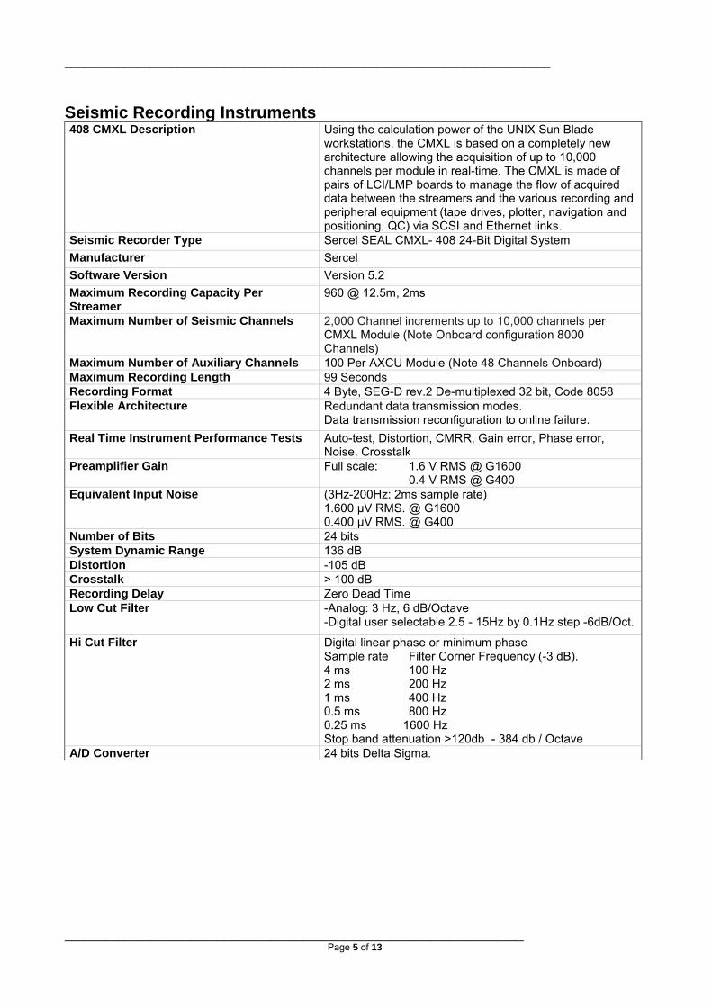
Seismic Recording Instruments 408 CMXL Description Using the calculation power of the UNIX Sun Blade
workstations, the CMXL is based on a completely new architecture allowing the acquisition of up to 10,000 channels per module in real-time. The CMXL is made of pairs of LCI/LMP boards to manage the flow of acquired data between the streamers and the various recording and peripheral equipment (tape drives, plotter, navigation and positioning, QC) via SCSI and Ethernet links.
Seismic Recorder Type Sercel SEAL CMXL- 408 24-Bit Digital System Manufacturer Sercel Software Version Version 5.2 Maximum Recording Capacity Per Streamer
960 @ 12.5m, 2ms
Maximum Number of Seismic Channels 2,000 Channel increments up to 10,000 channels per CMXL Module (Note Onboard configuration 8000 Channels)
Maximum Number of Auxiliary Channels 100 Per AXCU Module (Note 48 Channels Onboard) Maximum Recording Length 99 Seconds Recording Format 4 Byte, SEG-D rev.2 De-multiplexed 32 bit, Code 8058 Flexible Architecture Redundant data transmission modes.
Data transmission reconfiguration to online failure. Real Time Instrument Performance Tests Auto-test, Distortion, CMRR, Gain error, Phase error,
Noise, Crosstalk Preamplifier Gain Full scale: 1.6 V RMS @ G1600
0.4 V RMS @ G400 Equivalent Input Noise (3Hz-200Hz: 2ms sample rate)
1.600 µV RMS. @ G1600 0.400 µV RMS. @ G400
Number of Bits 24 bits System Dynamic Range 136 dB Distortion -105 dB Crosstalk > 100 dB Recording Delay Zero Dead Time Low Cut Filter -Analog: 3 Hz, 6 dB/Octave
-Digital user selectable 2.5 - 15Hz by 0.1Hz step -6dB/Oct.
Hi Cut Filter
Digital linear phase or minimum phase Sample rate Filter Corner Frequency (-3 dB). 4 ms 100 Hz 2 ms 200 Hz 1 ms 400 Hz 0.5 ms 800 Hz 0.25 ms 1600 Hz Stop band attenuation >120db - 384 db / Octave
A/D Converter 24 bits Delta Sigma.

_________________________________________________________________________
_____________________________________________________________________ Page 6 of 13
Tape Recording Subsystem Manufacturer IBM Tape Drives (Online) 2 x 3592 High Capacity Tape Drives Recording Format & Capacity SEG-D, Version 2- 512 Track – 60 Giga byte Media Type 3592 Cartridge Hardware Connections Fibre Channel
SEG-D File Server Recording Subsystem (SEAL Data Buffer) Manufacturer NetApp Function SEGD File Server and Archive Recording Format & Capacity SEG-D, Version 2 – 3 Terabyte Capacity Media Type RAID 5 Hard Disk Data Striping Hardware Connections Fibre Channel
Real Time QC System
eSQC Pro Description
eSQC Pro QC software package runs on a SUN workstation which is directly linked to the marine acquisition modules via a SCSI interface. All the seismic data are simultaneously sent to the tape drive and to eSQC Pro QC workstation for shot display, automatic trace attribute generation and trace header analysis. The operator defines the list of attributes to be display in real time for every shot.
Manufacturer Sercel
Seismic Display eSQC Pro QC provides high-resolution seismic record display with enhanced AGC, filtering and equalization.
Attribute Display
• Automatic first break picking. • Ambient noise level. • Seismic signal level. • Signal-to-noise ratio. • Seismic trace frequency analysis. • Capacitance value. • Cut off value. Each display can be a combination of seismic data and attributes.
Shot-by-shot attributes display (history)
Using bar graphs and color maps, eSQC Pro QC displays a summary of some important computed values, shot after shot: • Number of faulty traces with details of the problems. • Average level of ambient noise. • Ambient noise level per trace. • Seismic signal level per trace.
_________________________________________________________________________
_____________________________________________________________________ Page 7 of 13
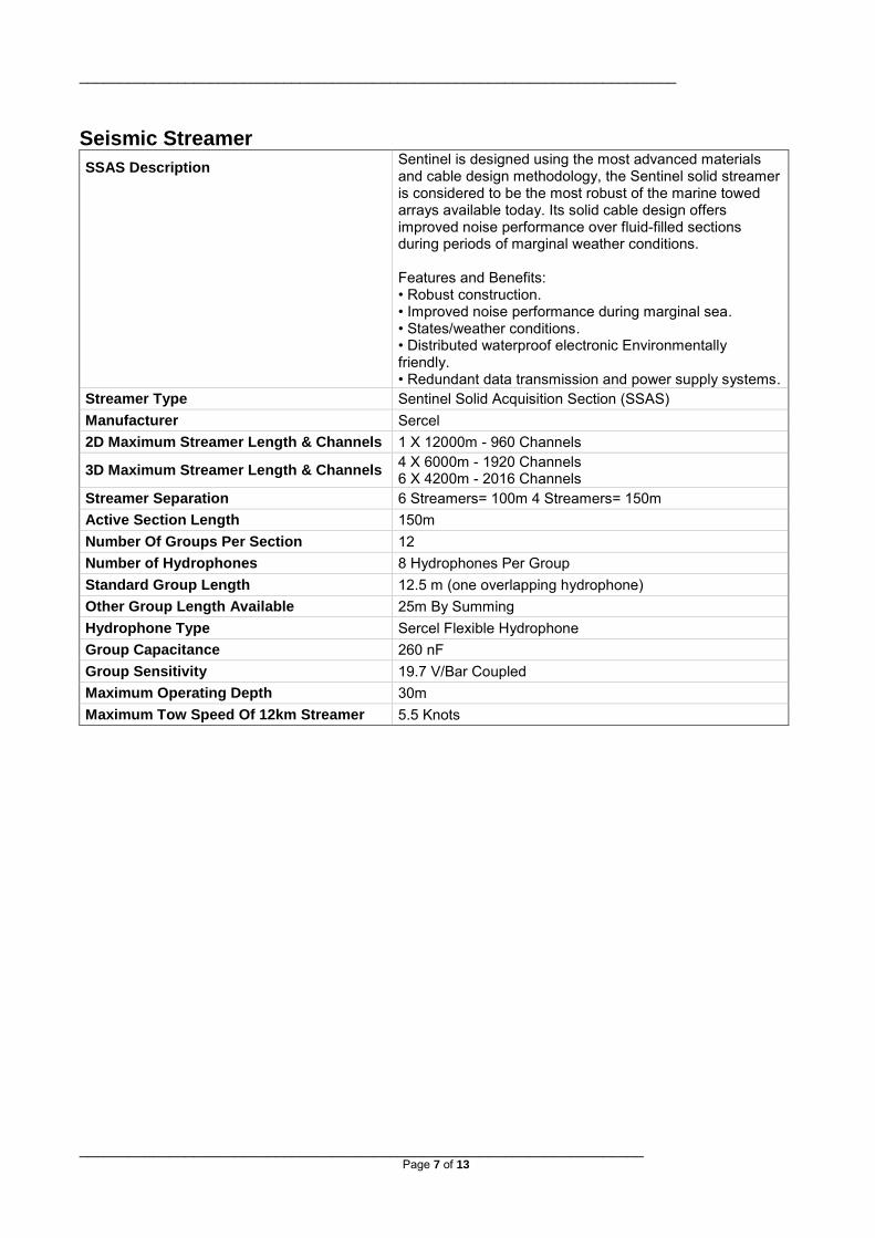
Seismic Streamer SSAS Description
Sentinel is designed using the most advanced materials and cable design methodology, the Sentinel solid streamer is considered to be the most robust of the marine towed arrays available today. Its solid cable design offers improved noise performance over fluid-filled sections during periods of marginal weather conditions. Features and Benefits: • Robust construction. • Improved noise performance during marginal sea. • States/weather conditions. • Distributed waterproof electronic Environmentally friendly. • Redundant data transmission and power supply systems.
Streamer Type Sentinel Solid Acquisition Section (SSAS) Manufacturer Sercel 2D Maximum Streamer Length & Channels 1 X 12000m - 960 Channels
3D Maximum Streamer Length & Channels 4 X 6000m - 1920 Channels 6 X 4200m - 2016 Channels
Streamer Separation 6 Streamers= 100m 4 Streamers= 150m Active Section Length 150m Number Of Groups Per Section 12 Number of Hydrophones 8 Hydrophones Per Group Standard Group Length 12.5 m (one overlapping hydrophone) Other Group Length Available 25m By Summing Hydrophone Type Sercel Flexible Hydrophone Group Capacitance 260 nF Group Sensitivity 19.7 V/Bar Coupled Maximum Operating Depth 30m Maximum Tow Speed Of 12km Streamer 5.5 Knots
_________________________________________________________________________
_____________________________________________________________________ Page 8 of 13
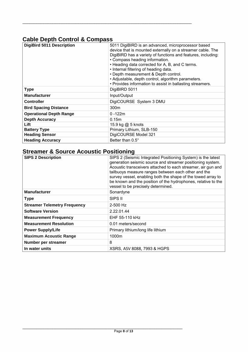
Cable Depth Control & Compass DigiBird 5011 Description
5011 DigiBIRD is an advanced, microprocessor based device that is mounted externally on a streamer cable. The DigiBIRD has a variety of functions and features, including: • Compass heading information. • Heading data corrected for A, B, and C terms. • Internal filtering of heading data. • Depth measurement & Depth control. • Adjustable, depth control, algorithm parameters. • Provides information to assist in ballasting streamers.
Type DigiBIRD 5011 Manufacturer Input/Output Controller DigiCOURSE System 3 DMU Bird Spacing Distance 300m Operational Depth Range 0 -122m Depth Accuracy 0.15m Lift 15.9 kg @ 5 knots Battery Type Primary Lithium, SLB-150 Heading Sensor DigiCOURSE Model 321 Heading Accuracy Better than 0.5°
Streamer & Source Acoustic Positioning SIPS 2 Description
SIPS 2 (Seismic Integrated Positioning System) is the latest generation seismic source and streamer positioning system. Acoustic transceivers attached to each streamer, air gun and tailbuoys measure ranges between each other and the survey vessel, enabling both the shape of the towed array to be known and the position of the hydrophones, relative to the vessel to be precisely determined.
Manufacturer Sonardyne Type SIPS II Streamer Telemetry Frequency 2-500 Hz Software Version 2.22.01.44 Measurement Frequency EHF 55-110 kHz Measurement Resolution 0.01 meters/second Power Supply/Life Primary lithium/long life lithium Maximum Acoustic Range 1000m Number per streamer 8 In water units XSRS, ASV 8088, 7993 & HGPS

_________________________________________________________________________
_____________________________________________________________________ Page 9 of 13
Streamer Recovery Device (SRD) SRD-500S Description
The SRD-500S is the latest generation marine streamer recovery device. SRD-500S recovery devices are installed at 600m intervals along the streamer. If a streamer is severed or becomes detached from the tow vessel and sinks, the recovery device automatically detonates at a water depth of 48m and releases compressed CO2 into a floatation bag. After the SRD bag inflates, the streamer floats with the SRD to surface for recovery.
Manufacturer Concord Type SRD-500S Fixed Activation Depth 48m SRD Spacing Distance 600m Battery Life 8 Years
Tailbuoy Manufacturer Partnerplast
Power Supply Powered From Streamer And Onboard Generator
Tailbuoy Positioning Buoylink EX Description
The BuoyLink Ex is RGPS Tracking System which has an intelligent bi-directional communication link which allows the operator to monitor, reconfigure and maintain each remote module in the network up to a range of 12Km.
Manufacturer Seamap Type Buoylink EX Range 12Km Radio Telemetry Output 902 to 928MHz (Spread Spectrum) @ 1 Watt Acoustic SIPS II XSRS 1 Per Tailbuoy
RGPS & Acoustic on Gun Arrays Manufacturer Seamap Type Buoylink EX Number of RGPS 1 on each string Range 1Km Radio Telemetry Output 902 to 928MHz (Spread Spectrum) @ 1 Watt Acoustic SIPS II HGPS 1 Per Gun String

_________________________________________________________________________
_____________________________________________________________________ Page 10 of 13
Integrated Navigation System Spectra Description
Spectra is a integrated seismic navigation system and is considered to be an indusrty stanadard, Spectra is based on an expandable network of Unix/Linux workstations with a dedicated real time navigation sensor acquisition system and is highly developed for complex 3D surveys. The design of Spectra is based around a central data Server process which acts as the information bank and data broker for the system. Data produced by the system’s producer processes are stored by the data server and made available on demand to the consumer processes providing logging, display and quality control functionality.
Manufacturer Concept Systems Type & Software Version Spectra Version 12.10.01 Time Synchronization Adjusted by GPS once per second Navigation Trigger System PowerRTNU Logging Format UKOOA P190, P294 Navigation QC Spectra Quality Control module (time serial plots, histogram
plots, statistics, etc.)
Primary DGPS C-NAV Description The C-NAV RTG Network is a global system for the
distribution of dynamic GPS Precise Point Positioning corrections, giving the user the ability to measure his position anywhere in the world with exceptional reliability and unprecedented accuracy of better than 10 cm (4 inches). Because the differential GPS corrections are broadcast via Inmarsat geostationary satellites, the user needs no local reference stations or post-processing to get this exceptional accuracy. The worldwide coverage of the geostationary satellites delivers a consistent high level of accuracy virtually anywhere from 72° N to 72° S latitude.
Manufacture C&C Technologies Inc Type C-NAV 2050M Tracking Channels 24+2 1 PPS Output Yes Real time DGPS Accuracy Position (H) < 10 cm Real time DGPS Accuracy Position (V) < 15 cm Real time DGPS Accuracy of Velocity 0.01 m/s Corrections Star-Fire Network delivered via Inmarsat satellite system
_________________________________________________________________________
_____________________________________________________________________ Page 11 of 13
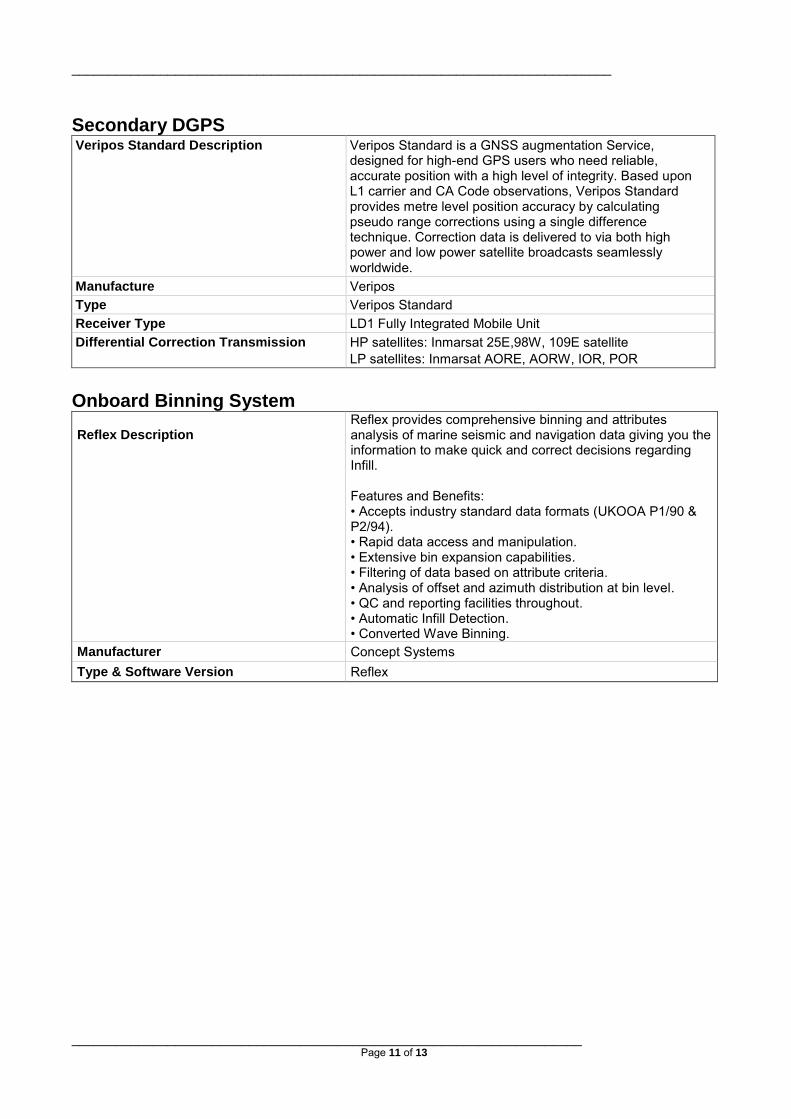
Secondary DGPS Veripos Standard Description Veripos Standard is a GNSS augmentation Service,
designed for high-end GPS users who need reliable, accurate position with a high level of integrity. Based upon L1 carrier and CA Code observations, Veripos Standard provides metre level position accuracy by calculating pseudo range corrections using a single difference technique. Correction data is delivered to via both high power and low power satellite broadcasts seamlessly worldwide.
Manufacture Veripos Type Veripos Standard Receiver Type LD1 Fully Integrated Mobile Unit Differential Correction Transmission HP satellites: Inmarsat 25E,98W, 109E satellite
LP satellites: Inmarsat AORE, AORW, IOR, POR Onboard Binning System Reflex Description
Reflex provides comprehensive binning and attributes analysis of marine seismic and navigation data giving you the information to make quick and correct decisions regarding Infill. Features and Benefits: • Accepts industry standard data formats (UKOOA P1/90 & P2/94). • Rapid data access and manipulation. • Extensive bin expansion capabilities. • Filtering of data based on attribute criteria. • Analysis of offset and azimuth distribution at bin level. • QC and reporting facilities throughout. • Automatic Infill Detection. • Converted Wave Binning.
Manufacturer Concept Systems Type & Software Version Reflex

_________________________________________________________________________
_____________________________________________________________________ Page 12 of 13
Onboard Navigation Processing
Sprint Description
Sprint has established itself as the most effective navigation data processing system in the marine seismic industry. Sprint provides customers with a high level of confidence in the complete navigation data set, which is available within a few hours of acquisition. Features and Benefits: • Fast data processing from raw data (P2/91-P2/94)through to UKOOA P1/90. • Batch mode (multi-line) capability in all modules. • Comparison and verification of all data in contractor’s P1/90 file. • Automatic QC and exception reporting. • Variety of graphical analysis techniques. • Plots output to Postscript printer (full resolution). • Spatial attribute analysis.
Manufacturer Concept Systems Type & Software Version Sprint
Onboard Seismic Processing Software Paradigm Focus Description
Paradigm Focus is the industry’s leading seismic data processing system for generating 2D and 3D images of the subsurface. Its popularity is based on its breadth of geophysical applications, its unique combination of production and interactive seismic data processing, its maturity and stability, and its versatile programming environment for client-guided customization. Focus is the cornerstone of Paradigm’s seismic data analysis offering, conditioning seismic data for depth imaging, reservoir characterization and pore pressure prediction projects.
Manufacturer Paradigm Software Type & Version Focus Version 5.4
Onboard Seismic Processing Hardware Manufacturer IBM
Server Type Server Node IBM 3650 (32 CPU, Quad Core, 2.83GHz, 1333MHz)
Raid Storage Capacity 20 Terabyte RAID-10
Node Type 4 Node Two Quad Core (8 CPU per node) Intel Xeon Processors 3.0GHz with 16Gb memory per node
Networked to SEAL Yes
Tape Processing Subsystem Manufacturer IBM Tape Drives (Online) 1 x 3592 High Capacity Tape Drives Format & Capacity SEG-D, SEG-Y Version 2- 512 Track – 60 Giga byte Media Type 3592 Cartridge Hardware Connections Fibre Channel

_________________________________________________________________________
_____________________________________________________________________ Page 13 of 13
Seismic Offline Processing Plotter Manufacturer OYO Instruments Type & Width GS624-2 Direct Thermal Width 24” Function Offline Stacks Print Resolution 400 dpi
Miscellaneous Speed Log Doppler Speed Log DS-80 Echo Sounder Simrad EA 500 Vessel Mounted Current Profiler Nortek Gyrocompass Lobaster AHRS Vertical Velocity Profiler Valeport Series 600 MKII & Sonardyne ASV 8088

ConocoPhillips Global NVE Greenland LTD. - 7 - Final Supplemental Filing 20 June 2012
APPENDIX B: VESSEL PARTICULARS FOR CHASE SHIPS


MV ARCTIC STAR
OWNER: MANAGEMENT: Artic shipsholding AS Besi AS Postboks 4423, Eidkjosen Midnattsolvn.9 9100 Kvaløysletta 9024 Tomasjord Contact: Contact: Bengt Are Korneliussen Signe Nina Korneliussen Tlf : +47 97 09 83 26 Tlf : +47 48 17 35 55 E-Mail : [email protected] E-Mail: [email protected] Vesselcontact: Mail to: [email protected] Mob.phone: +47 97 78 63 30 Iridium: 88 16 51 44 75 55
TECHNICAL SPECIFICATION
FOR MV ARCTIC STAR
MAIN DESCRIPTION MEASUREMENTS Type Guard vessel Length o.a. 32.98 m Classification INSB Length b.p.p. Vessel built 1973 Breath moulded. 6,70m Vessel Converted 2006 Depth moulded. 4,80m Name/Callsign ARCTIC STAR/V3NJ8 Draught , Max IMO No. 7311458 Freeboard, min Port of reg. Belize City Tonnage 265 BT Flag Belize Net Tonnage 80 NT
CARGO CAPACITIES DISCHARGE RATES Deck area 65 m2 Loading Load capacity 200 m2 Fuel 85 tons Water 20 tons
ACCOMMODATION Cabin 6 x 2 /2 x 1 = 14 men Hospital Y/N Yes Mess 20 m2 Bed for casualties 1 Cool store/Freezer 5 m2 Seating area 25
MACHINERY Main Eng 800 HK Type Alpha (2006) Main generators 2 x 150 Kw Type Stamford Bow thruster No Stren thruster No Max speed 13 knots/2300 ltr per day Service speed 10 knots/1600 ltr per day Bollard pull 15 tons Port consumtion 200 Ltr per days Propeller
DECK EQUIPMENT SAFETY/SECURITY 1 x new crane 1 x mob 2 x ankerwinch 2 x 10 tons Rapp Hydema Trawl winshes
2 x liferaft, 24 person
ELECTRONICS 1 x Decca radar 1 x Robertson Gyro compass
1 x Furuno Radar Far 28x7
1 x Robertson autopilot 1 x Ecco sounder 1 x ice light 1 x Scancontrol 4 x VHF Skanti 1 x Gmdss Skanti 3 x GPS Koden 1 x Max Sea tel. chart
All particulars are believed to be correct but not guaranteed