Connectivity Fault Management - IEEE 802 Fault Management IEEE 802.1 Tutorial, Portland, July 12,...
56
1 Connectivity Fault Management IEEE 802.1 Tutorial, Portland, July 12, 2004 Connectivity Fault Management Norman Finn
Transcript of Connectivity Fault Management - IEEE 802 Fault Management IEEE 802.1 Tutorial, Portland, July 12,...
1Connectivity Fault Management IEEE 802.1 Tutorial, Portland, July 12, 2004
Connectivity Fault ManagementNorman Finn

222Connectivity Fault Management IEEE 802.1 Tutorial, Portland, July 12, 2004
• IEEE P802.1ag is a work in progress.
• Some of the information in this slide deck reflects consensus among IEEE 802.1 and ITU-T Q.3/13 participants.
• Some of the information in this slide deck reflects only the opinions of the author.
• Until P802.1ag and/or Y.17ethoam are approved, there is no reliable means for distinguishing opinion from consensus.
DISCLAIMER

333Connectivity Fault Management IEEE 802.1 Tutorial, Portland, July 12, 2004
What is Metro EthernetConnectivity Fault Management?
• CFM: Standard Ethernet frames, distinguished from ordinary data frames only by destination MAC address and/or EtherType, and seen, relayed, and/or terminated by Provider Bridges.
L2
“L1”Ethernet
over SONETEthernet
over MPLS10G
EthernetATM
RFC1483
Edge Bridge
Bridge
Bridge
Bridge
Edge Bridge
switch
switch
Router
Router
Router
ATM
Switch
ATM
Switch
444Connectivity Fault Management IEEE 802.1 Tutorial, Portland, July 12, 2004
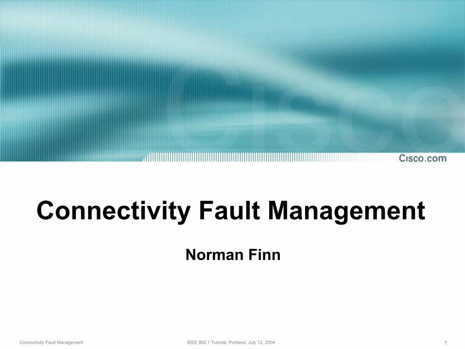
IEEE 802.3ah OAM versus802.1ag CFM = ITU-T Q.3/13 EthOAM
Drafting in progress.Standard approved by IEEE 802.
Joint effort by IEEE 802.1, ITU-T.Created by one committee.
Multiple instances operating at multiple levels simultaneously.
Single instantiation per physical link.
Connectivity Verification, Traceroute, Ping, (Alarm Suppression?).
Discovery, Variable request & response, Event notification, Information, Loopback mode.
May be per-service or per-wire. Passes “end-to-end” through bridges.
Operates on physical link only. Cannot pass through a bridge.
Connectivity Fault Management
IEEE 802.3ah OAM
Both are TLV based, both will (likely) allow vendor-specific TLVs.

555Connectivity Fault Management IEEE 802.1 Tutorial, Portland, July 12, 2004
• Customer contracts with Provider for end-to-end service.
• Provider contracts with Operator(s) to provide equipment and networks.
• Provider and Operator(s) may or may not be the same company or same division.
The OAM Environment

666Connectivity Fault Management IEEE 802.1 Tutorial, Portland, July 12, 2004
• Physical view of a network using CFM
The View From Above
UNIsBridges
Links in use
Provider Domain
Operator 2 Domain
Operator 1 Domain
Unused Links
Customer Domain

777Connectivity Fault Management IEEE 802.1 Tutorial, Portland, July 12, 2004
• Customer’s view from above
The View From Above
Provider DomainCustomer Domain
MEPs
MIPs
Bridges
Links in use

888Connectivity Fault Management IEEE 802.1 Tutorial, Portland, July 12, 2004
• Provider’s view from above
The View From Above
MEPs
MIPs
Bridges
Links in use
Provider Domain
Operator 2 Domain
Operator 1 Domain

999Connectivity Fault Management IEEE 802.1 Tutorial, Portland, July 12, 2004
• Operators’ view from above
The View From Above
MEPs
MIPs
Bridges
Links in use
Operator 2 Domain
Operator 1 Domain
Unused Links

101010Connectivity Fault Management IEEE 802.1 Tutorial, Portland, July 12, 2004
• Physical view from above
The View From Above
MEPs
Links
Bridges

111111Connectivity Fault Management IEEE 802.1 Tutorial, Portland, July 12, 2004
Provider Domain
• Let’s take a slice along one path …
The View From Above
MEPs
MIPs
Bridges
Links in use
Operator 2 Domain
Operator 1 Domain
Unused Links

121212Connectivity Fault Management IEEE 802.1 Tutorial, Portland, July 12, 2004
• We can see the MIP/MEP relationships.
Longitudinal View
Two MEPs, two MIPs visible to the Customer
Two MEPs, two MIPs visible to the Provider
Each Operator sees only his own MEPs and MIPs
Physical links are, presumably, controlled via 802.3ah OAM
CustomerEquipment
CustomerEquipment
Operator 1Provider Bridges
Operator 2Provider Bridges

131313Connectivity Fault Management IEEE 802.1 Tutorial, Portland, July 12, 2004
• Let’s look at one port from an end view …
Longitudinal View
Customer Level
Provider Level
Operator Level
Physical Level
CustomerEquipment
CustomerEquipment
Operator 1Provider Bridges
Operator 2Provider Bridges

141414Connectivity Fault Management IEEE 802.1 Tutorial, Portland, July 12, 2004
• From the end, we see the multiplexing.
Longitudinal View
Provider Bridge
Link toCustomer

15Connectivity Fault Management IEEE 802.1 Tutorial, Portland, July 12, 2004
CFM Packet Types

161616Connectivity Fault Management IEEE 802.1 Tutorial, Portland, July 12, 2004
In every CFM packet, there is a:• Maintenance Level
Customer level, Provider level, etc.
• Globally Unique Service Identifier LabelPerhaps based on a DNS name.
• Transmitting MEP IdentifierUnique only within the Service.
• Transaction IdentifierA sequence number.
What’s in a CFM Packet?

171717Connectivity Fault Management IEEE 802.1 Tutorial, Portland, July 12, 2004
• Continuity Check
• Traceroute
• Loopback (Ping)
• Alarm Indication?
• Other?
CFM Packet Types

18Connectivity Fault Management IEEE 802.1 Tutorial, Portland, July 12, 2004
Continuity Check

191919Connectivity Fault Management IEEE 802.1 Tutorial, Portland, July 12, 2004
How does a MEP know that the other MEPs, and thus the whole service, are working?
• It could “ping” each of the other MEPs.But, a point-to-point ping requires knowing the MAC addresses of the other MEPs, which requires either configuration (which makes hardware changes difficult) or discovery (which requires yet another protocol).
Also, point-to-point pings are inefficient.
Continuity Check

202020Connectivity Fault Management IEEE 802.1 Tutorial, Portland, July 12, 2004
• Each MEP transmits a periodic multicastContinuity Check Message inward towards the other MEPs.
• For each MEP, there is 1 transmission per time period and n receptions.
Continuity Check
Provider Domain

212121Connectivity Fault Management IEEE 802.1 Tutorial, Portland, July 12, 2004
• Each MEP sends CCs to announce itself to the others.• Some ports have multiple MEPs at different levels, or facing
in different directions.
Continuity Check
Customer Level
Provider Level
Operator Level
Physical Level

222222Connectivity Fault Management IEEE 802.1 Tutorial, Portland, July 12, 2004
What is in a Continuity Check Message?• Destination MAC address is tied to the ME Level
of the packet, to make it easier to confine CCs to a particular domain (Provider, Operator, etc.).
• ME Level, Service Identifier, MEP Identifier, Transaction Identifier.
• Lifetime.
• (Optional) Arbitrary data, software checksum.
• (Perhaps) Port state? Layer 3 management address? Transmission time?
Continuity Check

232323Connectivity Fault Management IEEE 802.1 Tutorial, Portland, July 12, 2004
What does the receiver do with a CC? It …
• Verifies that the Service Identifier matches;
• Verifies that the MEP ID doesn’t match;
• Catalogues the information by MEP ID;
• Refreshes the catalogued Lifetime;
• Checks the Transaction ID sequence; and
• (Optional) Processes optional info.
Continuity Check
242424Connectivity Fault Management IEEE 802.1 Tutorial, Portland, July 12, 2004
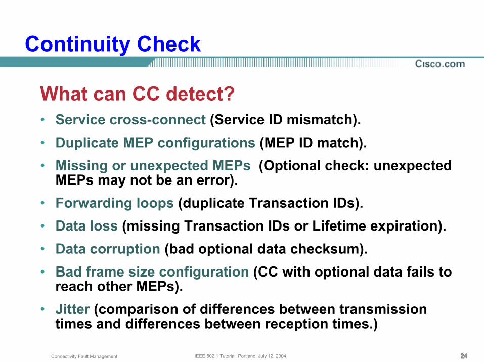
What can CC detect?• Service cross-connect (Service ID mismatch).• Duplicate MEP configurations (MEP ID match).• Missing or unexpected MEPs (Optional check: unexpected
MEPs may not be an error).• Forwarding loops (duplicate Transaction IDs).• Data loss (missing Transaction IDs or Lifetime expiration).• Data corruption (bad optional data checksum).• Bad frame size configuration (CC with optional data fails to
reach other MEPs).• Jitter (comparison of differences between transmission
times and differences between reception times.)
Continuity Check

252525Connectivity Fault Management IEEE 802.1 Tutorial, Portland, July 12, 2004
What is the output from CC?• Each MEP has a MIB that lists the
configured list of other MEPs (if any) and the catalogue of active MEPs received from CCs.
• The catalogue also records the MAC addresses of the other MEPs in the service at this ME Level.
• Failures are normally reported to the network manager via SNMP traps.
Continuity Check

26Connectivity Fault Management IEEE 802.1 Tutorial, Portland, July 12, 2004
Traceroute

272727Connectivity Fault Management IEEE 802.1 Tutorial, Portland, July 12, 2004
• This is not IP Traceroute!Ethernet has no TTL (Time To Live) counter that is altered hop-by-hop in the data plane.
• CFM Traceroute determines the path from a MEP to a given MAC address.
That given MAC address is normally another MEP’s MAC address.
That MAC address was learned from Continuity Check messages.
Traceroute

282828Connectivity Fault Management IEEE 802.1 Tutorial, Portland, July 12, 2004
• MEP sends a Traceroute Message to a destination MAC address that will cause it to be stopped by any MEP or MIP at the ME Level of the Traceroute.
This is easiest if Traceroute uses the same destination MAC address as the Continuity Checks of the next-lower level.
• Each receiving MEP or MIP sends a unicast Traceroute Reply to the original MEP.
Traceroute

292929Connectivity Fault Management IEEE 802.1 Tutorial, Portland, July 12, 2004
• Each receiving MEP sends a Traceroute Reply directly to the Originating MEP, and regenerates the Traceroute Message.
• If a MIP is not sure where to send the Traceroute Message, the trail ends.
Traceroute
Provider DomainTargetMEP
OriginatingMEP
12
3

303030Connectivity Fault Management IEEE 802.1 Tutorial, Portland, July 12, 2004
• MEPs at one ME Level are MIPs at some higher level.
Traceroute
Customer Level sees edges of Provider Service in Traceroute
Provider Level sees edges of Operator networks in Traceroute
Each Operator sees only his own MEPs and (hardware) MIPs
Physical links have no MIPs
CustomerEquipment
CustomerEquipment
Operator 1Provider Bridges
Operator 2Provider Bridges

313131Connectivity Fault Management IEEE 802.1 Tutorial, Portland, July 12, 2004
But, what if the traced MAC address has been forgotten?
• MIPs can take copies of Continuity Checksand catalogue them, perhaps in software by source MAC address only in a “CC Database”.
• This database allows Traceroute to follow “forgotten” links, and thus return useful information.
Traceroute

323232Connectivity Fault Management IEEE 802.1 Tutorial, Portland, July 12, 2004
What is in a Traceroute Message?• Destination MAC address is tied to the ME Level
of the packet, to make it easier to confine CCs to a particular domain (Provider, Operator, etc.).
• ME Level, Service Identifier, MEP Identifier, Transaction Identifier.
• TTL. (To prevent Traceroute from looping forever, even if data plane has a loop.)
• Target MAC address.
• Originating MEP’s MAC address.
Traceroute

333333Connectivity Fault Management IEEE 802.1 Tutorial, Portland, July 12, 2004
What is in a Traceroute Reply?• The Transaction ID and TTL from the Traceroute
Message, so that the replies can be coordinated.• Information about each MIP through which the
Traceroute Message flowed.There may be 1 or 2 in a single bridge.Information includes the MIPs’ MAC addresses.
• The identity of the next hop (in P802.1ab LLDP terms).
• Information about the reason for forwarding or not forwarding the Traceroute Message (e.g. MAC address forgotten, destination reached).
Traceroute

343434Connectivity Fault Management IEEE 802.1 Tutorial, Portland, July 12, 2004
What is the output from Traceroute?• The results of the Traceroute fill a MIB for
inspection by the Network Administrator.
• These results provider the MEP with a list of the MIPs and their MAC addresses for use in Loopback Messages.
Traceroute

35Connectivity Fault Management IEEE 802.1 Tutorial, Portland, July 12, 2004
Loopback
363636Connectivity Fault Management IEEE 802.1 Tutorial, Portland, July 12, 2004
What is in a Loopback Message?• Unicast MAC address of target.
• ME Level, Service Identifier, MEP Identifier, Transaction Identifier.
• (Optional) Arbitrary data, software checksum.
• (Perhaps) Transmission time? Reply time?
Loopback
373737Connectivity Fault Management IEEE 802.1 Tutorial, Portland, July 12, 2004
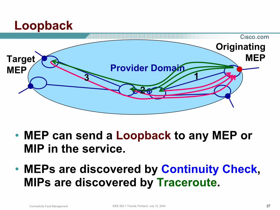
• MEP can send a Loopback to any MEP or MIP in the service.
• MEPs are discovered by Continuity Check, MIPs are discovered by Traceroute.
Loopback
Provider DomainTargetMEP
OriginatingMEP
12
3

383838Connectivity Fault Management IEEE 802.1 Tutorial, Portland, July 12, 2004
What is Loopback Good for?• Loopback follows the unicast data path,
not the multicast path.
• Sending Loopback to successive MIPs can determine the location of a fault.
• Sending a high volume of Loopback Messages can test bandwidth, reliability, or jitter of a service.
Loopback

39Connectivity Fault Management IEEE 802.1 Tutorial, Portland, July 12, 2004
Alarm Indication Signal

404040Connectivity Fault Management IEEE 802.1 Tutorial, Portland, July 12, 2004
What is AIS?• When a MEP discovers an error,
presumably a Continuity Check failure, it transmits periodic AIS in the opposite direction from that in which it runs the CCs.
• The AIS includes a Lifetime TLV that causes it to expire after a certain time.
• AIS transmission ceases if the failure is repaired via Spanning Tree.
Alarm Indication Signal

414141Connectivity Fault Management IEEE 802.1 Tutorial, Portland, July 12, 2004
• Failure causes MEP to generate AISs in opposite direction of Continuity Check.
Alarm Indication Signal
424242Connectivity Fault Management IEEE 802.1 Tutorial, Portland, July 12, 2004
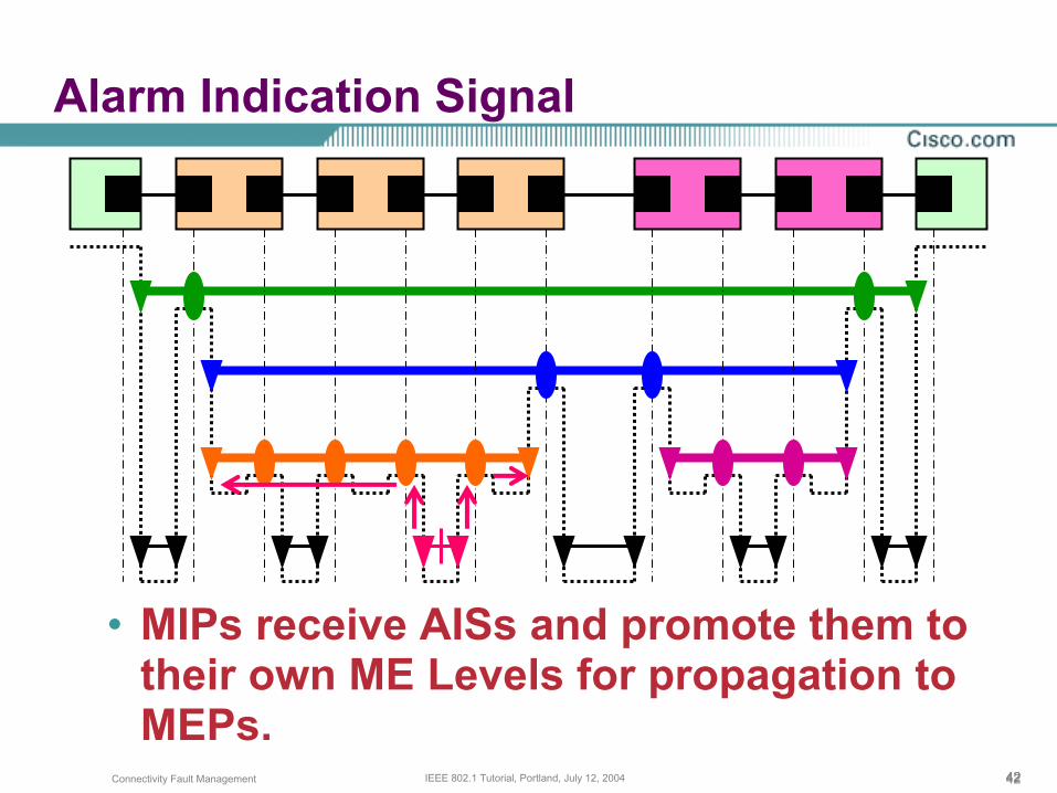
• MIPs receive AISs and promote them to their own ME Levels for propagation to MEPs.
Alarm Indication Signal

434343Connectivity Fault Management IEEE 802.1 Tutorial, Portland, July 12, 2004
• MEP may propagate or terminate AIS.
• Propagation is shown.
Alarm Indication Signal

444444Connectivity Fault Management IEEE 802.1 Tutorial, Portland, July 12, 2004
What is AIS Good for?• Receiving MEPs may catalogue AIS and
wait to see whether their own CCs report a failure.
If Spanning Tree repairs error, none need be generated.
If not, Network Administrator has already been notified of the problem; error trap from MEP is suppressed in order to reduce unnecessary alarms.
Alarm Indication Signal

454545Connectivity Fault Management IEEE 802.1 Tutorial, Portland, July 12, 2004
What is AIS Good for?• Receiving MEPs may delay the
propagation of AISs.This gives Spanning Tree time to correct the problem before alarming higher levels.
• Receiving MEPs may take action to correct the failure reported by AIS.
This assumes that there is no Spanning Tree to correct the problem.
Alarm Indication Signal

464646Connectivity Fault Management IEEE 802.1 Tutorial, Portland, July 12, 2004
Multiplexing• There may be a one-to-many relationship
between lower and upper MEPs/MIPs on a given interface.
For example, one physical link may carry many service instances.
One Provider service instance may carry many Customer VLANs.
• This causes a multiplication of AISs.
Alarm Indication Signal
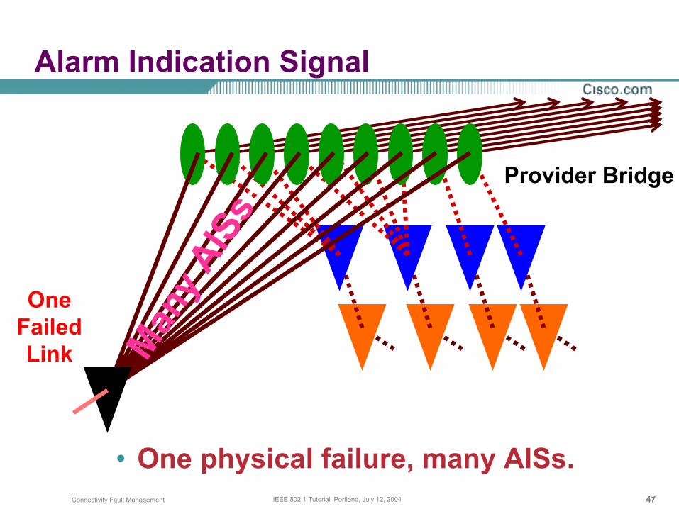
474747Connectivity Fault Management IEEE 802.1 Tutorial, Portland, July 12, 2004
• One physical failure, many AISs.
Alarm Indication Signal
Provider Bridge
OneFailedLink Man
y AIS
s

48Connectivity Fault Management IEEE 802.1 Tutorial, Portland, July 12, 2004
Other CFM Packet Types

494949Connectivity Fault Management IEEE 802.1 Tutorial, Portland, July 12, 2004
Discovery• Continuity Check provides MEP discovery.
Loopback to a multicast destination requires jitter timers to avoid implosions, and hence is no faster than Continuity Check.
IEEE 802.2 defined multicast Test and XID functions, which are the primary reason that these functions are disabled by default on most interfaces.
Other CFM Packet Types?

505050Connectivity Fault Management IEEE 802.1 Tutorial, Portland, July 12, 2004
Discovery• MIP discovery may be done with
Traceroute, one MEP at a time.
• A Traceroute for a multicast MAC target might trace an entire network in one large operation.
That is a heavy procedure.
But, N Traceroutes for N MEPs would be even heavier.
Other CFM Packet Types?

515151Connectivity Fault Management IEEE 802.1 Tutorial, Portland, July 12, 2004
Remote Defect Indication• Familiar (to some) from use in other
technologies.
• Ethernet does not support unidirectional links.
• RDI is meaningful only when unidirectional links are possible.
Other CFM Packet Types?
525252Connectivity Fault Management IEEE 802.1 Tutorial, Portland, July 12, 2004
Performance Management• It should be possible to piggyback
additional TLVs on Continuity Check and Loopback in order to measure performance.
• An additional PM OpCode may be desired to mark packets that require hardware assistance (e.g. timestamps) to produce meaningful data.
Other CFM Packet Types?

535353Connectivity Fault Management IEEE 802.1 Tutorial, Portland, July 12, 2004
Intrusive Loopback• Purpose is wire-speed bandwidth and forwarding
verification.• Similar to 802.3ah OAM Loopback, but loopback
function would swap source and destination MAC addresses, and would operate on a per-Service, instead of a per-MAC, basis.
• Requires “hardware” implementation to be useful.
• Is extremely dangerous in a shared medium service.
Other CFM Packet Types?

54Connectivity Fault Management IEEE 802.1 Tutorial, Portland, July 12, 2004
Summary
555555Connectivity Fault Management IEEE 802.1 Tutorial, Portland, July 12, 2004
• Both IEEE 802.1 and ITU-T Study Group 13 Question 3, are cooperating.
• The extra meetings are enabling the rapid progression of the standard(s).
• It remains to be seen whether there will be problems caused by having two groups working on the same problem, but so far, there is great promise for the successful completion of the standards.
Summary
Connectivity Fault Management IEEE 802.1 Tutorial, Portland, July 12, 2004


![Extending IEEE 802.1 AVB with Time-triggered Scheduling: A ... · The IEEE 802.1 Audio/Video Bridging (AVB) [1] suite, that is specified by the IEEE Time Sensitive Networking Group](https://static.fdocuments.us/doc/165x107/5f22a5ac3c174d46162c87f6/extending-ieee-8021-avb-with-time-triggered-scheduling-a-the-ieee-8021-audiovideo.jpg)