
ConnectionCenter 3228 All-in-one
12
ConnectionCenter 3228 All-in-one Instructions for use
Transcript of ConnectionCenter 3228 All-in-one

ConnectionCenter 3228 All-in-one
Instructions for use

2
Field of applicationThe connectionCenter 3228 All-in-one is used as the basis for refillable cartridges.
It supplies either softened, fully demineralised or deminera-lised water with pH value stabilisation for heating systems in accordance with VDI Guideline 2035 Part 1 and protects heating systems against lime deposits.
It is also used to automate the filling process in hot water heating systems.
The built-in BA backflow preventer according to DIN EN 1717 prevents the heating water from flowing back into the drin-king water pipe.
In this combination, the direct fixed connection of drinking water to the heating system is approved according to DIN EN 1717.
The integrated pressure reducer ensures the correct and constant pressure of the system.
DesignThe Connection Center All-in-one contains a digital capacity control, a shut-off valve on the inlet and outlet side, a sam-pling connection for soft water, a hardness measuring set, a wall bracket for installation, a BA backflow preventer accor-ding to DIN EN 1717, tundish, testing devices and a pressure reducer. Setting range of the pressure reducer between 1 and 5 bar. Screw connections on both sides.
Please order the already filled cartridges, which are availa-ble in 2.5, 4, 7, 14 and 30 litre versions for HWE (heating water softening) HVE (heating demineralisation) and HVE Plus (pH value stabilisation) and can be refilled with the corresponding granulate.
A conductivity sensor and pressure sensors are already in-tegrated in the digital capacity control.
The built-in pressure reducer ensures a constant set output pressure so that the heating system is protected against unwanted overpressure during the filling process.
Housing made of pressed brass. Internal parts and tundish made of high-quality plastic and NBR.
The plastic parts and elastomers in contact with the drin-king water comply with the KTW guideline of the Federal Environment Agency.
InstallationMount the wall bracket on the wall.
Make sure that the water supply line is installed in such a way that stagnation does not occur and that the escaping water can drain off with a free gradient.
Flush the pipe carefully before installing the connection centre.
Remove the pressure gauge plug.
Attach the wall bracket at this point of the connection centre and lock it in place using the screw connections.
Mount the drain valve on the other side.
The wall bracket optionally can be mounted on both sides.
An easily accessible installation location simplifies mainte-nance and inspection. Make sure that the location is pro-tected against flooding and frost and is well ventilated. The drain pipe must be provided with sufficient capacity.
In order to ensure permanent and perfect functioning, we recommend the installation of a drinking water filter accor-ding to DIN EN 13443, Part 1 immediately after the water meter.
The maintenance intervals of the BA backflow preventer must be observed. For connecting the tundish to the drai-nage system, the applicable standard DIN EN 12056 must be observed.
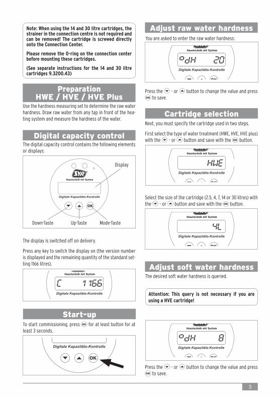
Down-Taste Up-Taste Mode-Taste
Display
3
Digital capacity control
Adjust raw water hardnessNote: When using the 14 and 30 litre cartridges, the strainer in the connection centre is not required and can be removed! The cartridge is screwed directly onto the Connection Center.
Please remove the O-ring on the connection center before mounting these cartridges.
(See separate instructions for the 14 and 30 litre cartridges 9.3200.43)
Preparation HWE / HVE / HVE Plus
Use the hardness measuring set to determine the raw water hardness. Draw raw water from any tap in front of the hea-ting system and measure the hardness of the water.
The digital capacity control contains the following elements or displays:
The display is switched off on delivery.
Press any key to switch the display on (the version number is displayed and the remaining quantity of the standard set-ting 1166 litres).
You are asked to enter the raw water hardness:
Press the - or button to change the value and press to save.
Press the - or button to change the value and press to save.
Cartridge selection
Start-up
Next, you must specify the cartridge used in two steps.
First select the type of water treatment (HWE, HVE, HVE plus) with the - or button and save with the button.
To start commissioning, press for at least button for at least 3 seconds.
Select the size of the cartridge (2.5, 4, 7, 14 or 30 litres) with the - or button and save with the button.
Adjust soft water hardness
Attention: This query is not necessary if you are using a HVE cartridge!
The desired soft water hardness is queried.
4
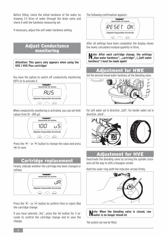
Adjust Conductance monitoring
Attention: This query only appears when using the HVE / HVE Plus cartridge!
You have the option to switch off conductivity monitoring (OFF) or to activate it.
When conductivity monitoring is activated, you can set limit values from 10 - 200 µS.
Cartridge replacement
Adjustment for HWE
Adjustment for HVE
Finally, indicate whether the cartridge has been changed or refilled.
Press the - or button to confirm (Yes) or reject (No) the cartridge change.
If you have selected „Yes“, press the button for 3 se-conds to confirm the cartridge change and to save the change.
After all settings have been completed, the display shows the newly calculated residual quantity in litres.
Note: After each cartridge change, the settings „Raw water hardness“, „cartridge“, („Soft water
hardness“) must be made again!
Set the desired mixed water hardness at the blending valve.
For soft water set in direction „Soft“, for harder water set in direction „Hard“.
Deactivate the blending valve by turning the spindle clock-wise all the way in with a hexagon socket.
Hold the outer ring (with the indicator arrow) firmly.
Note: When the blending valve is closed, raw water is no longer mixed in!
The system can now be filled.
Before filling, check the initial hardness of the water by drawing 2-3 litres of water through the drain valve and check it with the hardness measuring set.
If necessary, adjust the soft water hardness setting.
The following confirmation appears:
Press the - or button to change the value and press to save.

5
If there is no flow, a simple press of the button displays the volume recorded so far since the last cartridge change.
Displays
If the battery needs to be replaced, the following message is displayed.
To replace the battery, unscrew the cover and replace the battery (CR-2032). Pay attention to the correct polarity!
During filling, the display shows the current volume flow.
When the capacity of the cartridge is almost exhausted (10 - 1 % remaining capacity) the message „Cartridge al-most exhausted“ is displayed
When the cartridge is completely exhausted, the message „Cartridge exhausted“ appears - the cartridge must be replaced!
Adjustment of pressure reducer
Before you can fill the system with treated water, the pres-sure reducer may have to be adjusted.
The pressure reducer of the Connection centre All-in-one is factory set to 1.5 bar.
Please note that the inlet pressure must be at least 1 bar higher than the desired outlet pressure.
The pressure reducer can be adjusted as follows:
Unscrew the locking screw of the pressure reducer with a screwdriver.
To decrease the filling pressure, turn the adjustment handle in the direction of minus (-) and to increase in the direction of plus (+).
The set pressure and the pressure of the heating system is displayed in the digital capacity control.
Press the button 3 times in the main menu. Use the key to switch between input and output pressure.
After adjustment, retighten the locking screw to prevent acci-dental adjustment.
Note: Please note that the heating pressure is lower than the desired filling pressure.
If necessary, reduce or increase the pressure of the heating system to the desired filling pressure.
Display input pressure
Display Main menu
Display output pressure

6
The ball valve on the inlet side can be turned by 180° to simplify maintenance of the strainer.
Close both shut-off valves after completing the filling process to prevent uncontrolled refilling.
Maintenance -Checking the separation of
the backflow preventerThe isolating function as well as the function of the output check valve must be controlled annually in accordance with DIN EN 806, part 5, to ensure that the backflow preventer works properly.
Remove the manometer plug of the inlet and intermediate pressure zone (1 + 2).
Install the maintenance ball valves in place of the manometer plugs.
Mount the needle valves of the measuring instrument (e.g. 6600.00.000) to the maintenance ball valves 1 + 2.
Mount the measuring device and open the two shut-off valves.Close both shut-off valves for inspection.
Filling the heating systemOpen the two shut-off valves of the Connection centre All-in-one to start the filling process.

7
Vent the valve via the two needle valves. Then close the two needle valves again.
Close the two shut-off valves.
Open needle valve 1 and slowly release the pressure via need-le valve 1 (a few drops).
Close the needle valve again. Observe the tundish. The diffe-rential pressure must be above 140mbar and the inlet back-flow preventer (RV1) must close completely again, otherwise there is contamination or a mechanical defect.
Open the needle valve 1 further and relieve the medium pres-sure zone until it is completely drained.
Maintenance - inspection of check valve 2
To test the outlet check valve (RV 2), the intermediate pressu-re zone must first be completely drained.
Open the outlet shut-off valve.
If water drips from the tundish, there is a mechanical defect or contamination of the outlet check valve.
In this case the backflow preventer cartridge must be cleaned or replaced.
Close both maintenance ball valves, remove the measuring device and reinstall the pressure gauge plugs.
Open the two shut-off valves.

8
Remove check valve 2
Place the tool on top of the backflow preventer cartridge (1) and turn clockwise (2).
Turn the tool and place the tool from above on the backflow preventer 2.
Make sure that the two pins of the tool engage in the tabs of the cartridge.
Pull out the cartridge while turning it slightly and if necessa-ry, clean the cartridge with clear water.
Fixture for backflow preventer cartridge
Fixture for screwed seat
Use the replacement tool (6600.00.970) for removal.
Remove the cap.
Remove backflow preventerIt is necessary to disassemble the backflow preventer in case of a defect and if the backflow preventer cartridge is dirty and needs to be cleaned.
Close the inlet and outlet side shut-off valves.
Remove the heat insulation cover and unscrew the cap with the maintenance key (4807.00.906).

9
Make sure that the gaps of the tool engage with the pins of the check valve 2.
Remove the check valve 2 by unscrewing it counterclockwise.
The pressure reducer of the All-in-one connection centre must be serviced annually in accordance with DIN EN 806, Part 5.
Close the shut-off valve on the inlet and outlet side.
Reassemble in reverse order.Open the ball valves again.
Max. operating pressure: 10 barMax. operating temperature: 30 °C (inlet) 65 °C (outlet)Fluid: potable waterOutlet pressure: 1 - 5 bar (1,5 bar vorgestellt)Filling capacity: 0,5 m3/h at Dp 1,5 bar (4 - 30 litres cartridge) 0,3 m3/h at Dp 1,5 bar (2,5 litres cartridge)
Maintenance pressure reducer
Technical specifications
Reassemble in reverse order. Open the ball valves again.
Installation and maintenance may only be carried out by an authorised specialist. Observe the main-tenance instructions! Do not clean plastic parts with cleaning products containing solvents. After hard knocks or blows, the plastic part concerned must be replaced (even if there is no visible dama-ge). Strong pressure shocks must be avoided. The packaging serves as transport protection. If the packaging is considerably damaged, the valve must not be installed!
Unscrew the pressure reducer with the ring spanner (acces-sory 4807.00.906) counterclockwise and clean it with clear cold water.
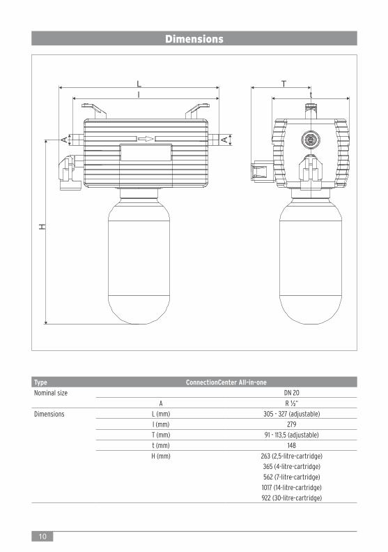
Type ConnectionCenter All-in-oneNominal size DN 20
A R ½“Dimensions L (mm) 305 - 327 (adjustable)
l (mm) 279T (mm) 91 - 113,5 (adjustable)t (mm) 148H (mm) 263 (2,5-litre-cartridge)
365 (4-litre-cartridge)562 (7-litre-cartridge)1017 (14-litre-cartridge)922 (30-litre-cartridge)
10
Dimensions

11
Spare parts / Accessories
❶
2
3
7
8
6
4
6
❶ Plug 3228.00.903
2 Backflow preventer cartridge, complete 6600.00.974
3 Digital capacity control 3228.00.905
4 Pressure reducer cartridge 0315.15.900
❺ Pressure sensor 3228.00.904
6 Blending valve, complete 3200.15.914
7 Tundish, complete 3228.00.901
8 Ring spanner 4807.00.906
❾ Replacement tool 6600.00.970
5

12 printed in Germany - 9.3228.14 2018 - Änderungen vorbehalten
Accessories
Hardness measuring set3000.00.913
Cartridges
Accessories
Resin
HWE 2,5 litre 3200.00.0214 litre 3200.00.0017 litre 3200.00.00314 litre 3200.00.00430 litre 3200.00.018
HVE 2,5 litre 3200.00.0224 litre 3200.00.0117 litre 3200.00.01314 litre 3200.00.01430 litre 3200.00.017
HVE Plus 2,5 litre 3200.00.0234 litre 3200.00.0157 litre 3200.00.00514 litre 3200.00.00630 litre 3200.00.016
HWE 2,5 litre 3200.00.9424 litre 3200.00.9047 litre 3200.00.90610 litre 3200.00.93714 litre = 2 x 7 litre30 litre = 3 x 10 litre
HVE 2,5 litre 3200.00.9434 litre 3200.00.9147 litre 3200.00.91610 litre 3200.00.93814 litre = 2 x 7 litre30 litre = 3 x 10 litre
HVE Plus 2,5 litre 3200.00.9444 litre 3200.00.9277 litre 3200.00.92610 litre 3200.00.93914 litre = 2 x 7 litre30 litre = 3 x 10 litre
Hans Sasserath GmbH & Co. KG • Tel.: +49 2161 6105-0 • Fax: +49 2161 6105-20Mühlenstraße 62 • D-41352 Korschenbroich • [email protected] • www.SYR.de


![My One My All My One My All [Db, 77 bpm, 4/4]My One My All-](https://static.fdocuments.us/doc/165x107/5e779fc6cdc8f45d522359cd/-my-one-my-all-my-one-my-all-db-77-bpm-44-my-one-my-all.jpg)
