Connecting Enterprises Over Service Provider … Enterprises Over Service Provider Networks...
34
© 2008 Cisco Systems, Inc. All rights reserved. Cisco Public Connecting Enterprises Over Service Provider Networks 1 Connecting Enterprises Over Service Provider Networks Boštjan Fele Network Consulting Engineer Advanced Services WWSP WiMax Practice
Transcript of Connecting Enterprises Over Service Provider … Enterprises Over Service Provider Networks...
© 2008 Cisco Systems, Inc. All rights reserved. Cisco PublicConnecting Enterprises Over Service Provider Networks 1
Connecting Enterprises Over Service Provider Networks
Boštjan Fele
Network Consulting Engineer
Advanced Services
WWSP WiMax Practice
© 2008 Cisco Systems, Inc. All rights reserved. Cisco PublicConnecting Enterprises Over Service Provider Networks 2
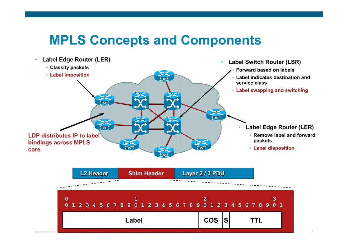
Agenda
� MPLS overview
� VPNs overview
� L3 VPNs
� L2 VPNs
� Inter-AS VPNs
© 2008 Cisco Systems, Inc. All rights reserved. Cisco PublicConnecting Enterprises Over Service Provider Networks 3
MPLS Concepts and Components
• Label Switch Router (LSR)
• Forward based on labels
• Label indicates destination and service class
• Label swapping and switching
• Label Edge Router (LER)
• Classify packets
• Label imposition
• Label Edge Router (LER)
• Remove label and forward packets
• Label disposition
Shim HeaderShim HeaderL2 HeaderL2 Header Layer 2 / 3 PDULayer 2 / 3 PDU
0 1 2 30 1 2 3
0 1 2 3 4 5 6 7 8 9 0 1 2 3 4 5 6 7 8 9 0 1 2 3 4 5 6 7 8 9 0 10 1 2 3 4 5 6 7 8 9 0 1 2 3 4 5 6 7 8 9 0 1 2 3 4 5 6 7 8 9 0 1
Label COS S TTL
LDP distributes IP to label
bindings across MPLS
core
© 2008 Cisco Systems, Inc. All rights reserved. Cisco PublicConnecting Enterprises Over Service Provider Networks 4
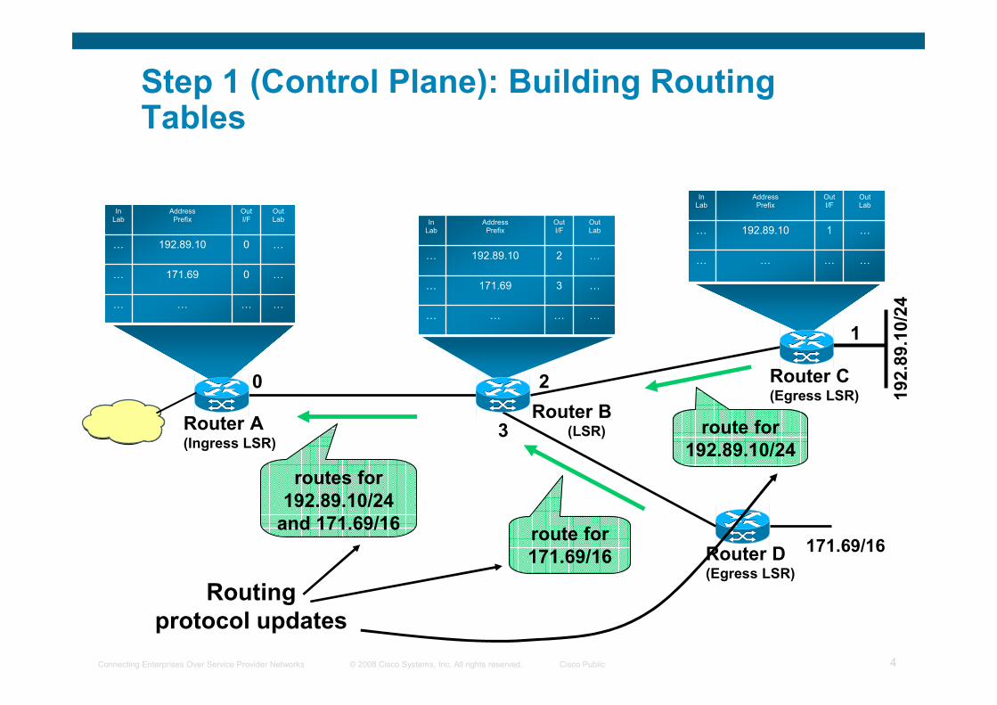
2
Router B(LSR)
0
Router A(Ingress LSR)
…0171.69…
…0192.89.10…
…………
OutLab
OutI/F
AddressPrefix
InLab
…2192.89.10…
…3171.69…
…………
OutLab
OutI/F
AddressPrefix
InLab
…………
…1192.89.10…
OutLab
OutI/F
AddressPrefix
InLab
1
Router C(Egress LSR)
Router D(Egress LSR)
171.69/16
routes for
192.89.10/24
and 171.69/16
route for
192.89.10/24
route for
171.69/16
3
192.89.10/24
Routing
protocol updates
Step 1 (Control Plane): Building Routing Tables
© 2008 Cisco Systems, Inc. All rights reserved. Cisco PublicConnecting Enterprises Over Service Provider Networks 5
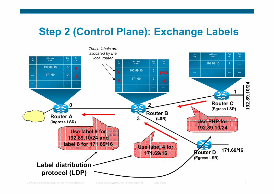
20
0171.69…
0192.89.10…
…………
OutLab
OutI/F
AddressPrefix
InLab
2192.89.10
3171.69
…………
OutLab
OutI/F
AddressPrefix
InLab
…………
…1192.89.10
OutLab
OutI/F
AddressPrefix
InLab
1
Router D 171.69/16
Use label 9 for
192.89.10/24 and
label 8 for 171.69/16
Use PHP for
192.89.10/24
Use label 4 for
171.69/16
3
192.89.10/24
-
pop
4
99
88
Label distribution
protocol (LDP)
Router B(LSR)Router A
(Ingress LSR)
Router C(Egress LSR)
Router D(Egress LSR)
These labels are
allocated by the
local router
Step 2 (Control Plane): Exchange Labels
© 2008 Cisco Systems, Inc. All rights reserved. Cisco PublicConnecting Enterprises Over Service Provider Networks 6
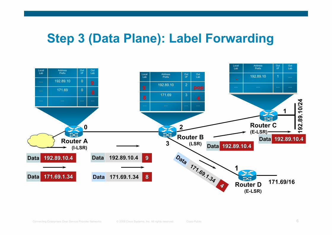
20
0171.69…
0192.89.10…
…………
OutLab
OutI/F
AddressPrefix
LocalLab
2192.89.10
3171.69
…………
OutLab
OutI/F
AddressPrefix
LocalLab
…………
…1192.89.10
OutLab
OutI/F
AddressPrefix
LocalLab
1
171.69/16
3
192.89.10/24
-
pop
4
99
88
1
192.89.10.4192.89.10.4Data
171.69.1.34171.69.1.34Data 88171.69.1.34171.69.1.34Data
192.89.10.4192.89.10.4Data 99
192.89.10.4192.89.10.4Data
192.89.10.4192.89.10.4Data
44
171.69.1.34
171.69.1.34
Data
Router B(LSR)Router A
(I-LSR)
Router C(E-LSR)
Router D(E-LSR)
Step 3 (Data Plane): Label Forwarding
© 2008 Cisco Systems, Inc. All rights reserved. Cisco PublicConnecting Enterprises Over Service Provider Networks 7
Agenda
� MPLS overview
� VPNs overview
� L3 VPNs
� L2 VPNs
� Inter-AS VPNs
© 2008 Cisco Systems, Inc. All rights reserved. Cisco PublicConnecting Enterprises Over Service Provider Networks 8
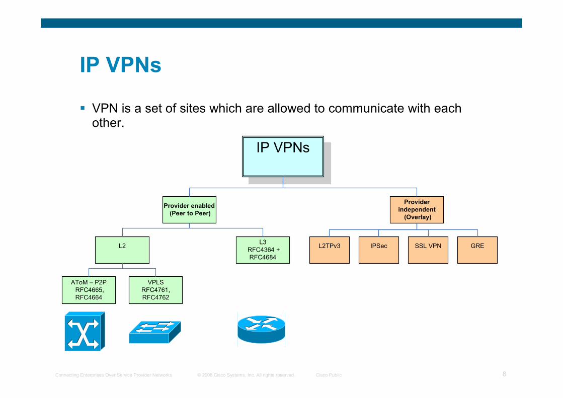
IP VPNs
� VPN is a set of sites which are allowed to communicate with eachother.
IP VPNs
Provider enabled
(Peer to Peer)
Provider
independent
(Overlay)
L2L3
RFC4364 +
RFC4684
IPSec SSL VPNL2TPv3 GRE
AToM – P2P
RFC4665,
RFC4664
VPLS
RFC4761,
RFC4762
© 2008 Cisco Systems, Inc. All rights reserved. Cisco PublicConnecting Enterprises Over Service Provider Networks 9
Agenda
� MPLS overview
� VPNs overview
� L3 VPNs
� L2 VPNs
� Inter-AS VPNs
© 2008 Cisco Systems, Inc. All rights reserved. Cisco PublicConnecting Enterprises Over Service Provider Networks 10
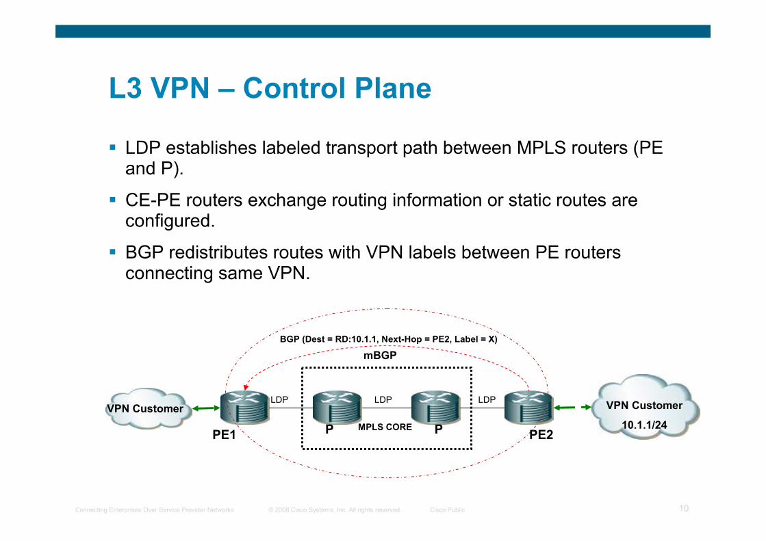
L3 VPN – Control Plane
� LDP establishes labeled transport path between MPLS routers (PE and P).
� CE-PE routers exchange routing information or static routes are configured.
� BGP redistributes routes with VPN labels between PE routers connecting same VPN.
mBGP
MPLS CORE
LDP LDP LDP
PE1 PE2P P
VPN Customer VPN Customer
10.1.1/24
BGP (Dest = RD:10.1.1, Next-Hop = PE2, Label = X)
© 2008 Cisco Systems, Inc. All rights reserved. Cisco PublicConnecting Enterprises Over Service Provider Networks 11
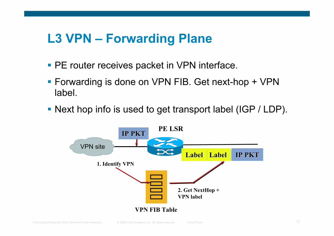
L3 VPN – Forwarding Plane
� PE router receives packet in VPN interface.
� Forwarding is done on VPN FIB. Get next-hop + VPN label.
� Next hop info is used to get transport label (IGP / LDP).
VPN FIB Table
1. Identify VPN
2. Get NextHop +
VPN label
PE LSR
LabelLabel IP PKTIP PKT
IP PKTIP PKT
VPN site
LabelLabel
© 2008 Cisco Systems, Inc. All rights reserved. Cisco PublicConnecting Enterprises Over Service Provider Networks 12
Agenda
� MPLS overview
� VPNs overview
� L3 VPNs
� L2 VPNs
� Inter-AS VPNs
© 2008 Cisco Systems, Inc. All rights reserved. Cisco PublicConnecting Enterprises Over Service Provider Networks 13
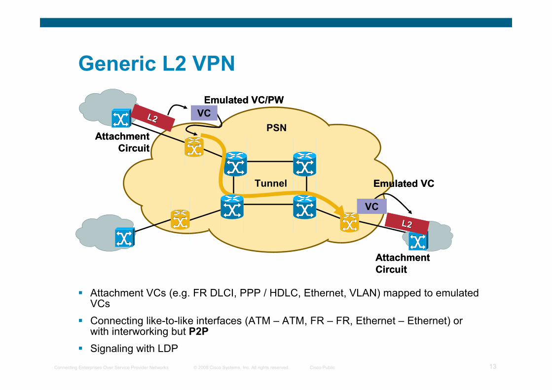
Generic L2 VPN
� Attachment VCs (e.g. FR DLCI, PPP / HDLC, Ethernet, VLAN) mapped to emulated VCs
� Connecting like-to-like interfaces (ATM – ATM, FR – FR, Ethernet – Ethernet) or with interworking but P2P
� Signaling with LDP
L2L2
Attachment
Circuit
L2L2
Attachment
Circuit
VC
Emulated VC
VC
Emulated VCTunnel
VC
Emulated VC/PW
VC
Emulated VC/PW
L2L2
Attachment
Circuit
L2L2
Attachment
Circuit
PSN
© 2008 Cisco Systems, Inc. All rights reserved. Cisco PublicConnecting Enterprises Over Service Provider Networks 14
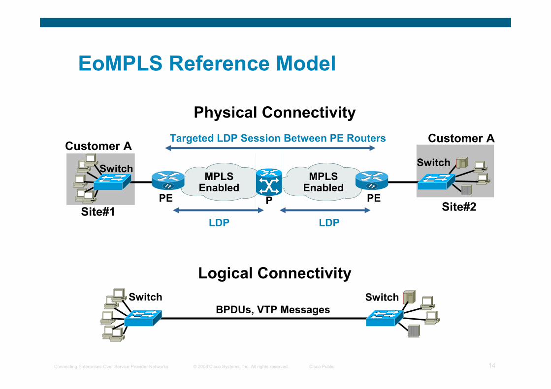
Customer A
Site#2
MPLSEnabled
MPLSEnabled
Targeted LDP Session Between PE Routers
PEPE P
Logical Connectivity
BPDUs, VTP Messages
Physical Connectivity
EoMPLS Reference Model
SwitchSwitch
Customer A
Site#1
Switch Switch
LDP LDP
© 2008 Cisco Systems, Inc. All rights reserved. Cisco PublicConnecting Enterprises Over Service Provider Networks 15
MPLS
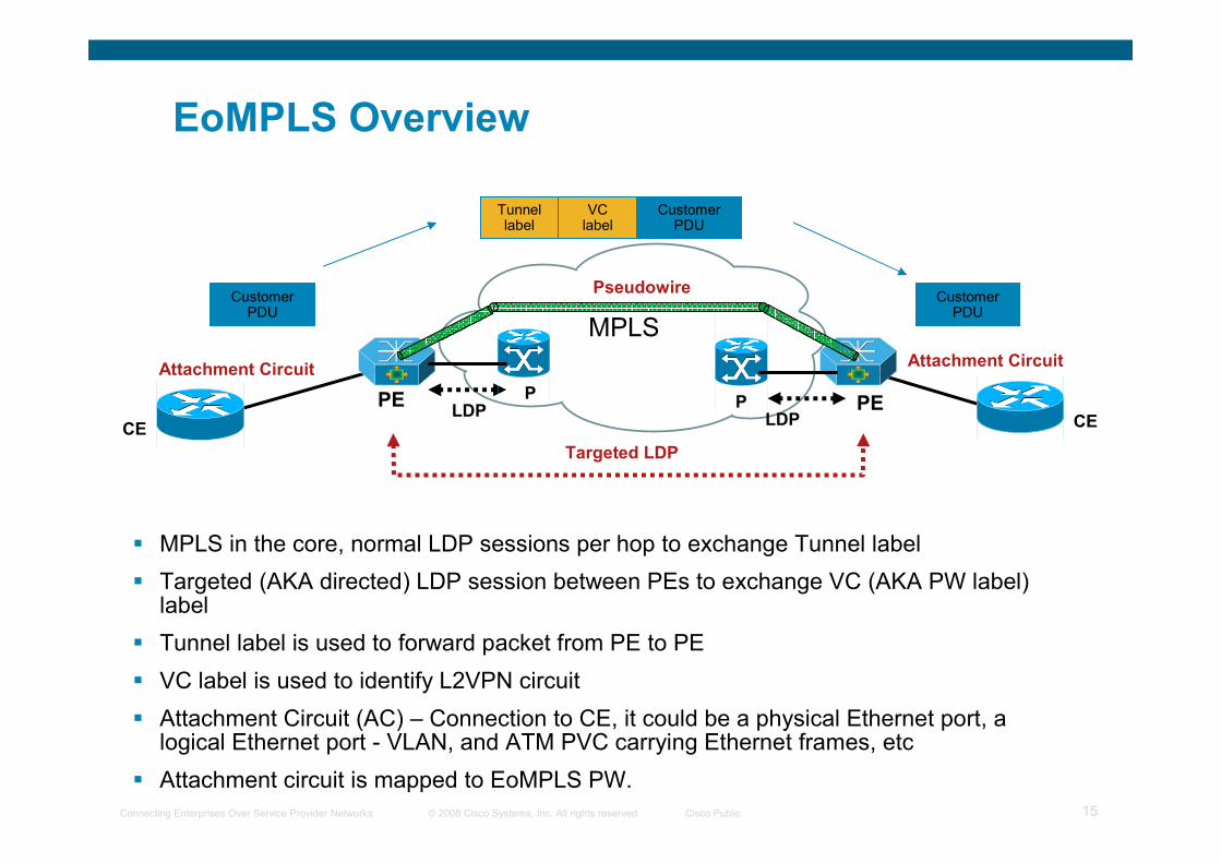
EoMPLS Overview
� MPLS in the core, normal LDP sessions per hop to exchange Tunnel label
� Targeted (AKA directed) LDP session between PEs to exchange VC (AKA PW label) label
� Tunnel label is used to forward packet from PE to PE
� VC label is used to identify L2VPN circuit
� Attachment Circuit (AC) – Connection to CE, it could be a physical Ethernet port, a logical Ethernet port - VLAN, and ATM PVC carrying Ethernet frames, etc
� Attachment circuit is mapped to EoMPLS PW.
Pseudowire
PE PPE
CE CELDP
LDP
Targeted LDP
Attachment CircuitAttachment Circuit
P
Tunnel label
Customer PDU
VC label
Customer PDU
Customer PDU
© 2008 Cisco Systems, Inc. All rights reserved. Cisco PublicConnecting Enterprises Over Service Provider Networks 16
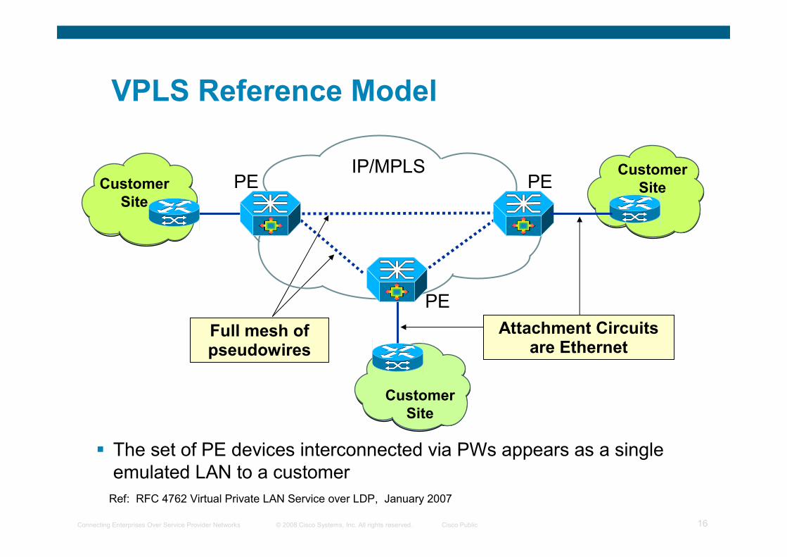
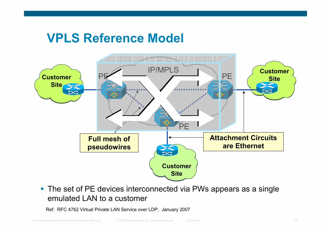
VPLS Reference Model
PE PEIP/MPLS
Attachment Circuits are Ethernet
Customer
Site
Full mesh of pseudowires
Customer
Site
� The set of PE devices interconnected via PWs appears as a single
emulated LAN to a customer
PE
Customer
Site
Ref: RFC 4762 Virtual Private LAN Service over LDP, January 2007
© 2008 Cisco Systems, Inc. All rights reserved. Cisco PublicConnecting Enterprises Over Service Provider Networks 17
VPLS Reference Model
PE PEIP/MPLS
Attachment Circuits are Ethernet
Customer
Site
Full mesh of pseudowires
Customer
Site
� The set of PE devices interconnected via PWs appears as a single
emulated LAN to a customer
PE
Customer
Site
Ref: RFC 4762 Virtual Private LAN Service over LDP, January 2007
© 2008 Cisco Systems, Inc. All rights reserved. Cisco PublicConnecting Enterprises Over Service Provider Networks 18
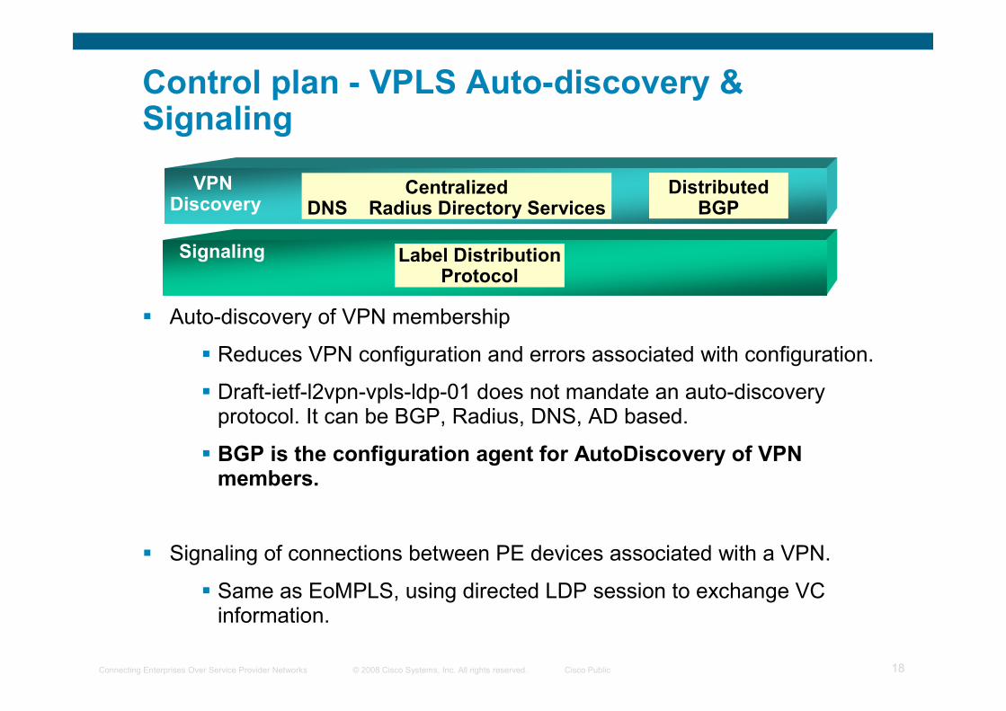
Control plan - VPLS Auto-discovery & Signaling
� Auto-discovery of VPN membership
� Reduces VPN configuration and errors associated with configuration.
� Draft-ietf-l2vpn-vpls-ldp-01 does not mandate an auto-discovery protocol. It can be BGP, Radius, DNS, AD based.
� BGP is the configuration agent for AutoDiscovery of VPN members.
� Signaling of connections between PE devices associated with a VPN.
� Same as EoMPLS, using directed LDP session to exchange VC information.
VPN Discovery
Signaling
CentralizedDNS Radius Directory Services
DistributedBGP
Label DistributionProtocol
© 2008 Cisco Systems, Inc. All rights reserved. Cisco PublicConnecting Enterprises Over Service Provider Networks 19
Layer 2 Forwarding Instance Requirements
� Flooding/Forwarding:
– Forwarding based on [VLAN, Destination MAC Address]
– Unknwon Ucast/Mcast/Broadcast – Flood to all ports (IGMP snooping can be used to constrain multicast flooding)
� MAC Learning/Aging:
– Dynamic learning based on Source MAC and VLAN
– Refresh aging timers with incoming packet
� Loop Prevention:
– Split Horizon + Full Mesh
– Spanning Tree (possible but not desirable)
A Virtual Switch MUST operate like a conventional L2 switch!
© 2008 Cisco Systems, Inc. All rights reserved. Cisco PublicConnecting Enterprises Over Service Provider Networks 20
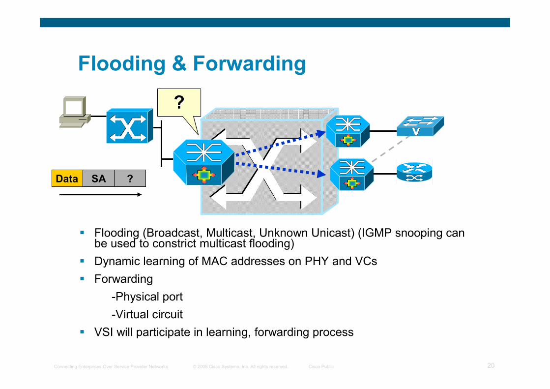
Flooding & Forwarding
� Flooding (Broadcast, Multicast, Unknown Unicast) (IGMP snooping can be used to constrict multicast flooding)
� Dynamic learning of MAC addresses on PHY and VCs
� Forwarding
-Physical port
-Virtual circuit
� VSI will participate in learning, forwarding process
Data SA ?
???
© 2008 Cisco Systems, Inc. All rights reserved. Cisco PublicConnecting Enterprises Over Service Provider Networks 21
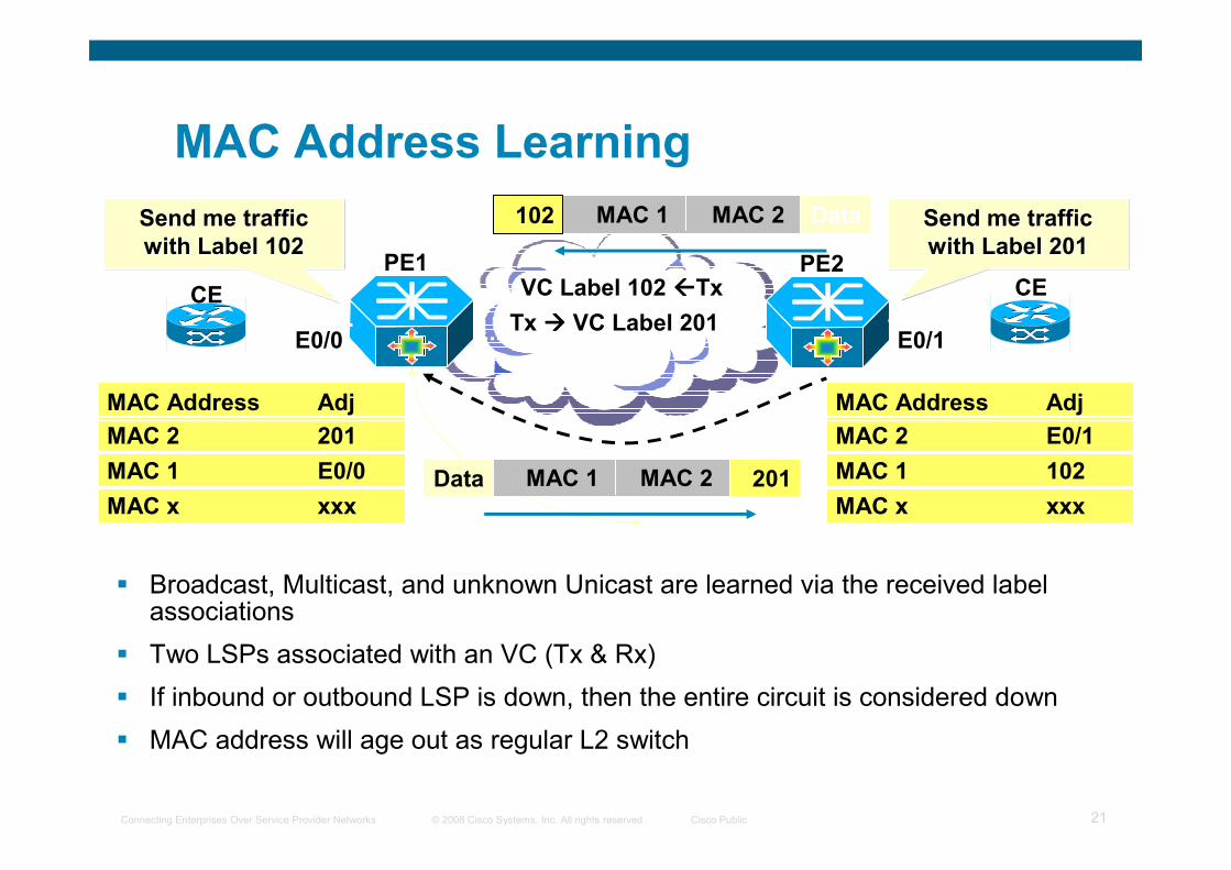
MAC Address Learning
� Broadcast, Multicast, and unknown Unicast are learned via the received label associations
� Two LSPs associated with an VC (Tx & Rx)
� If inbound or outbound LSP is down, then the entire circuit is considered down
� MAC address will age out as regular L2 switch
PE1 PE2
Send me traffic
with Label 201
Send me traffic Send me traffic
with Label 201with Label 201
VC Label 102 ����Tx
Tx ���� VC Label 201
Send me traffic
with Label 102
Send me traffic Send me traffic
with Label 102with Label 102
CECE
Data MAC 1 MAC 2 201
DataMAC 1 MAC 2102
E0/0 E0/1
MAC 2 E0/1
MAC Address Adj
MAC 1 102
MAC x xxx
MAC 2 201
MAC Address Adj
MAC 1 E0/0
MAC x xxx
© 2008 Cisco Systems, Inc. All rights reserved. Cisco PublicConnecting Enterprises Over Service Provider Networks 22
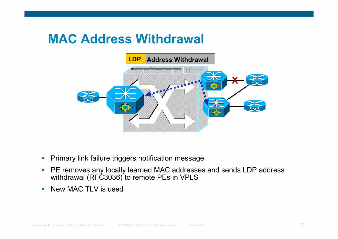
MAC Address Withdrawal
� Primary link failure triggers notification message
� PE removes any locally learned MAC addresses and sends LDP address withdrawal (RFC3036) to remote PEs in VPLS
� New MAC TLV is used
X
LDP Address Withdrawal
© 2008 Cisco Systems, Inc. All rights reserved. Cisco PublicConnecting Enterprises Over Service Provider Networks 23
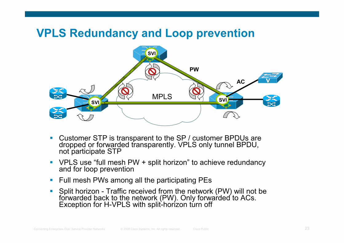
VPLS Redundancy and Loop prevention
� Customer STP is transparent to the SP / customer BPDUs are dropped or forwarded transparently. VPLS only tunnel BPDU, not participate STP
� VPLS use “full mesh PW + split horizon” to achieve redundancy and for loop prevention
� Full mesh PWs among all the participating PEs
� Split horizon - Traffic received from the network (PW) will not be forwarded back to the network (PW). Only forwarded to ACs. Exception for H-VPLS with split-horizon turn off
MPLS
SVI
SVISVI
AC
PW
© 2008 Cisco Systems, Inc. All rights reserved. Cisco PublicConnecting Enterprises Over Service Provider Networks 24
Agenda
� MPLS overview
� VPNs overview
� L3 VPNs
� L2 VPNs
� Inter-AS VPNs
© 2008 Cisco Systems, Inc. All rights reserved. Cisco PublicConnecting Enterprises Over Service Provider Networks 25
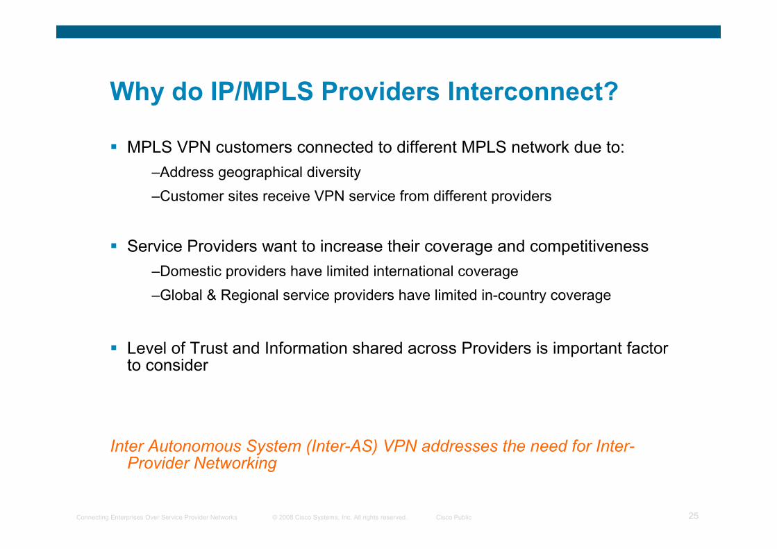
Why do IP/MPLS Providers Interconnect?
� MPLS VPN customers connected to different MPLS network due to:
–Address geographical diversity
–Customer sites receive VPN service from different providers
� Service Providers want to increase their coverage and competitiveness
–Domestic providers have limited international coverage
–Global & Regional service providers have limited in-country coverage
� Level of Trust and Information shared across Providers is important factor to consider
Inter Autonomous System (Inter-AS) VPN addresses the need for Inter-Provider Networking
© 2008 Cisco Systems, Inc. All rights reserved. Cisco PublicConnecting Enterprises Over Service Provider Networks 26
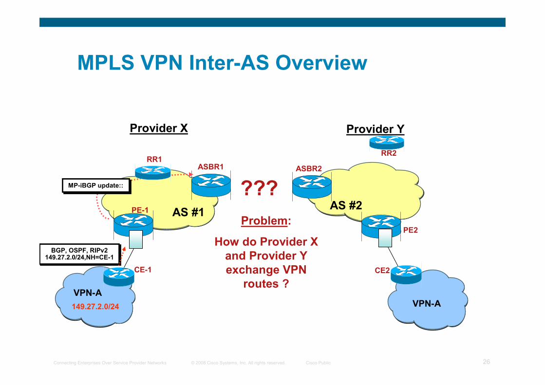
MPLS VPN Inter-AS Overview
VPN-A
VPN-A
PE-1
PE2
CE2 CE-1
AS #1AS #2
149.27.2.0/24
MP-iBGP update::MP-iBGP update::
BGP, OSPF, RIPv2 149.27.2.0/24,NH=CE-1
BGP, OSPF, RIPv2 149.27.2.0/24,NH=CE-1
Problem:
How do Provider X
and Provider Y
exchange VPN
routes ?
???
ASBR1 ASBR2
RR2RR1
Provider X Provider Y
© 2008 Cisco Systems, Inc. All rights reserved. Cisco PublicConnecting Enterprises Over Service Provider Networks 27
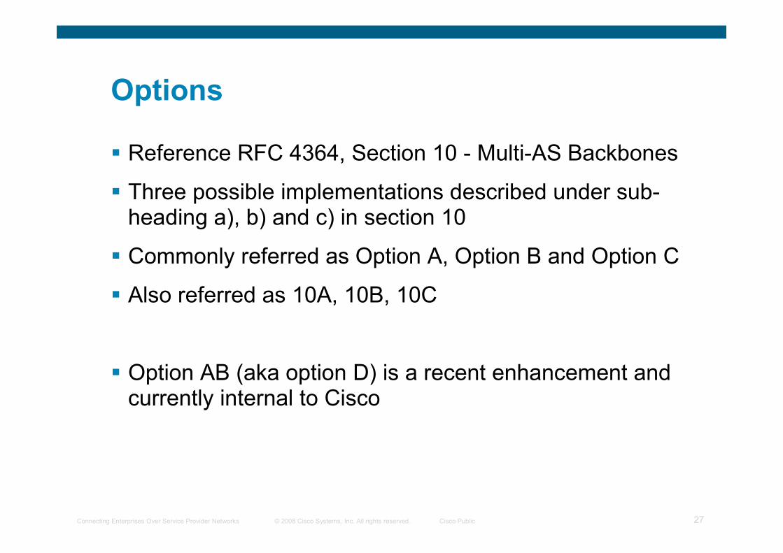
Options
� Reference RFC 4364, Section 10 - Multi-AS Backbones
� Three possible implementations described under sub-heading a), b) and c) in section 10
� Commonly referred as Option A, Option B and Option C
� Also referred as 10A, 10B, 10C
� Option AB (aka option D) is a recent enhancement and currently internal to Cisco
© 2008 Cisco Systems, Inc. All rights reserved. Cisco PublicConnecting Enterprises Over Service Provider Networks 28
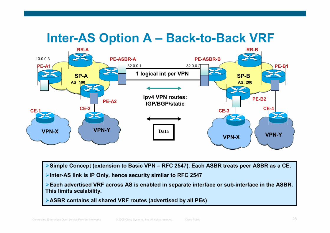
CE-1
PE-B1
VPN-X
PE-A1
VPN-Y
PE-A2
CE-2
RR-A
VPN-X
PE-B2
CE-3CE-4
RR-B
PE-ASBR-A PE-ASBR-B
SP-A SP-B
Data
Ipv4 VPN routes:
IGP/BGP/static
1 logical int per VPN
VPN-Y
�Simple Concept (extension to Basic VPN – RFC 2547). Each ASBR treats peer ASBR as a CE.
�Inter-AS link is IP Only, hence security similar to RFC 2547
�Each advertised VRF across AS is enabled in separate interface or sub-interface in the ASBR. This limits scalability.
�ASBR contains all shared VRF routes (advertised by all PEs)
10.0.0.3
32.0.0.1 32.0.0.2
AS: 100 AS: 200
Inter-AS Option A – Back-to-Back VRF
© 2008 Cisco Systems, Inc. All rights reserved. Cisco PublicConnecting Enterprises Over Service Provider Networks 29
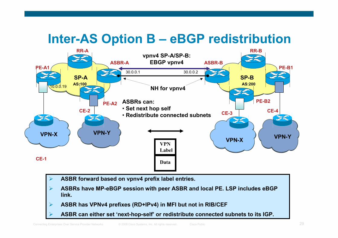
Inter-AS Option B – eBGP redistribution
CE-1
VPN-Y
PE-B1
Data
VPN-X
PE-A1
VPN-Y
PE-A2
CE-2
RR-A
VPN-X
PE-B2
CE-3CE-4
RR-B
ASBR-A ASBR-B
SP-A SP-B
vpnv4 SP-A/SP-B:
EBGP vpnv4
VPN
Label
NH for vpnv4
ASBRs can:
• Set next hop self
• Redistribute connected subnets
� ASBR forward based on vpnv4 prefix label entries.
� ASBRs have MP-eBGP session with peer ASBR and local PE. LSP includes eBGPlink.
� ASBR has VPNv4 prefixes (RD+IPv4) in MFI but not in RIB/CEF
� ASBR can either set ‘next-hop-self’ or redistribute connected subnets to its IGP.
30.0.0.1 30.0.0.2
AS:100 AS:20010.0.0.19
© 2008 Cisco Systems, Inc. All rights reserved. Cisco PublicConnecting Enterprises Over Service Provider Networks 30
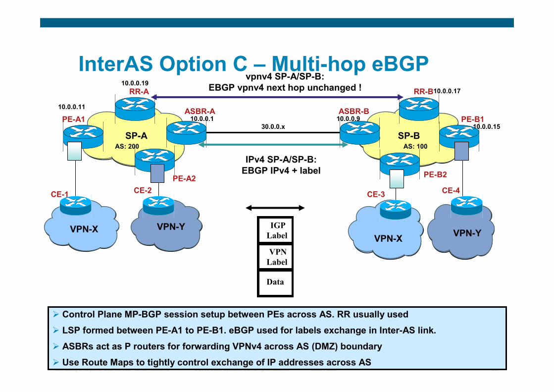
InterAS Option C – Multi-hop eBGP
VPN-X
PE-A1
VPN-Y
PE-A2
CE-2CE-1
RR-A
VPN-Y
PE-B1
VPN-X
PE-B2
CE-3CE-4
RR-B
ASBR-A ASBR-B
SP-A SP-B
Data
IPv4 SP-A/SP-B:
EBGP IPv4 + label
vpnv4 SP-A/SP-B:
EBGP vpnv4 next hop unchanged !
VPN
Label
IGP
Label
� Control Plane MP-BGP session setup between PEs across AS. RR usually used
� LSP formed between PE-A1 to PE-B1. eBGP used for labels exchange in Inter-AS link.
� ASBRs act as P routers for forwarding VPNv4 across AS (DMZ) boundary
� Use Route Maps to tightly control exchange of IP addresses across AS
AS: 200 AS: 100
10.0.0.11
10.0.0.19
10.0.0.1 10.0.0.9
10.0.0.17
10.0.0.1530.0.0.x
© 2008 Cisco Systems, Inc. All rights reserved. Cisco PublicConnecting Enterprises Over Service Provider Networks 31
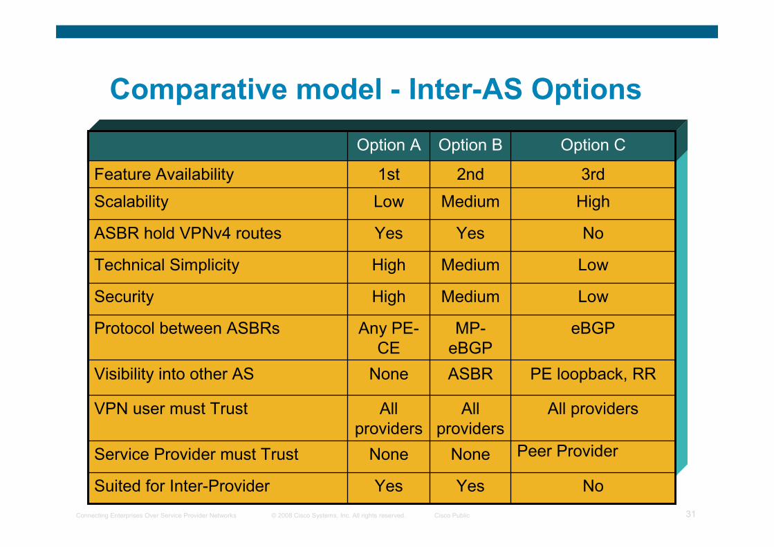
Comparative model - Inter-AS Options
NoYesYesSuited for Inter-Provider
Peer ProviderNoneNoneService Provider must Trust
All providersAll
providers
All
providers
VPN user must Trust
PE loopback, RRASBR NoneVisibility into other AS
eBGPMP-
eBGP
Any PE-
CE
Protocol between ASBRs
LowMedium HighSecurity
LowMediumHighTechnical Simplicity
NoYesYesASBR hold VPNv4 routes
HighMediumLowScalability
3rd2nd1stFeature Availability
Option COption BOption A
© 2008 Cisco Systems, Inc. All rights reserved. Cisco PublicConnecting Enterprises Over Service Provider Networks 32
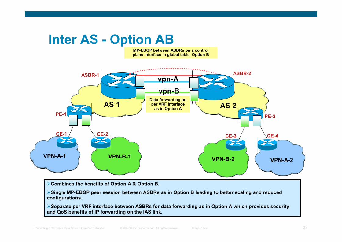
Inter AS - Option AB
VPN-A-1
PE-1
VPN-B-1
CE-2CE-1
ASBR-1
AS 1
MP-EBGP between ASBRs on a control plane interface in global table, Option B
VPN-A-2
PE-2
CE-4 CE-3
VPN-B-2
ASBR-2
AS 2Data forwarding on per VRF interface as in Option A
vpn-B
vpn-A
�Combines the benefits of Option A & Option B.
�Single MP-EBGP peer session between ASBRs as in Option B leading to better scaling and reduced configurations.
�Separate per VRF interface between ASBRs for data forwarding as in Option A which provides security and QoS benefits of IP forwarding on the IAS link.

© 2008 Cisco Systems, Inc. All rights reserved. Cisco PublicConnecting Enterprises Over Service Provider Networks 33
Q and A
© 2008 Cisco Systems, Inc. All rights reserved. Cisco PublicConnecting Enterprises Over Service Provider Networks 34