Chapter 16 Connecting LANs, Backbone Networks, and Virtual LANs
NIST Technical Note 1609
Connecting Buildings to Public Safety Networks
Alan B. Vinh David G. Holmberg
NIST Technical Note 1609
CoPublic Safety Networks
Building Environment DivisionBuilding and Fire Research Laboratory
June, 2009
National Institute of Standards and Technology
Patrick Gallagher, Acting Director
nnecting Buildings to
Alan B. Vinh David G. Holmberg
U.S. Department of Commerce Gary Locke, Secretary
Disclaimer Certain trade names, documents, organizations, protocols and technologies are referenced in this paper. Such identification is not intended to imply recommendation or endorsement by the National Institute of Standards and Technology, nor is it intended to imply that these entities are necessarily the best available for the purpose.
National Institute of Standards and Technology Technical Note XXXX Natl. Inst. Stand. Technol. Tech. Note XXXX, NNN pages (Month and Year)
ii
Abstract The operation of modern commercial buildings uses digital control systems which monitor a vast amount of sensors. These sensors in turn produce data that is available for building control but also can be mission-critical for effective emergency response. First responders can be notified of designated building alerts in real-time so that actions can be performed promptly. The capability to monitor building devices and to keep the first responder community updated with the latest building information during emergency situations, as well as the ability to remotely control certain building devices and processes, can be realized. This paper presents a framework for standards-based communication of real-time building alerts, via public safety networks, to 9-1-1 dispatch and into the hands of emergency responders. This research will assist in the development and deployment of commercial products with new levels of capability for situational awareness to help save lives and properties in emergency situations.
Keywords alarm; alert; authentication; authorization; building information and control systems; emergency preparedness; emergency response; public safety networks; secure data exchange
iii
TABLE OF CONTENTS
1. Introduction..................................................................................................................................1 2. Building Emergency Response Scenario.....................................................................................4
2.1 Building Automated Alerts ........................................................................................... 4 2.2 Mapping Alerts to Floorplans ....................................................................................... 4 2.3 External Alerts .............................................................................................................. 5 2.4 Incident Assessment...................................................................................................... 5 2.5 Communicating with the Building................................................................................ 5
3. Monitoring and Sending Alerts....................................................................................................8 4. Data Encapsulation for an Alert.................................................................................................12 5. Classifying and Categorizing Alerts ..........................................................................................13
5.1 Common Alerting Protocol Message Overview......................................................... 13 5.2 Alert Categories .......................................................................................................... 15 5.3 Alert Event Types ....................................................................................................... 15 5.4 Alert Event Types and Their Related Categories ....................................................... 16
6. The Standard Access Point ........................................................................................................17 7. Connecting Back to the Building...............................................................................................19 8. The Building Floorplan..............................................................................................................21 9. Locating a Device within the Floorplan.....................................................................................21 10. Conclusions..............................................................................................................................22 11. References................................................................................................................................23
iv

v
LIST OF FIGURES
Figure 1 Proposed Next Generation Network Communications for First Responders................... 2 Figure 2 The BISACS Base Server and Its Internal Building Networks...................................... 10 Figure 3 The BISACS Network of Servers................................................................................... 11 Figure 4 Sample Common Alerting Protocol Message ................................................................ 12 Figure 5 Common Alerting Protocol Document Object Model.................................................... 14 Figure 6 The Application Specific Client User Interface ............................................................. 20 Figure 7 Alert Status Screen ......................................................................................................... 21
LIST OF TABLES
Table 1 Building Source Data Classification for Emergency Response Purposes ......................... 6 Table 2 Alert Event Types and Their Categories.......................................................................... 17

1. Introduction The operation of modern buildings uses control systems that connect to a vast array of devices and sensors. These sensors can be used to monitor pertinent information for daily operation as well as emergency scenarios [1]. For the purposes of emergency response, there needs to be a standards-based framework for public safety officials to connect to all buildings in a geographical area and monitor building automation system (BAS) generated alerts. However, there is no standard method to enable this information transfer. This lack of a cohesive set of standards hinders the delivery of mission-critical data into the hands of public safety officials, and hinders the development of tools and methods that could use this data to improve the performance and safety of first responders in addressing emergency building incidents. To date, there are many building automation systems using proprietary monitoring methods which hinder sensor integration within the building. Therefore, from the building itself, there is a challenge to gather building incident (emergency alert) data. The goal is to have a standard central data server that can connect to BAS sensors via a standard building side communication protocol. This data server is explained in more detail in this paper, and will be referred to as the Building Information Services and Control System Base Server (BISACS Base Server, or BBS) [2]. The BBS in turn presents alert data to external public safety officials via a standard framework referred to as the Standard Access Point (SAP). External to buildings, there are many public safety networks and organizations, each typically designed to monitor its own jurisdiction(s) and there is no standard framework for communication between these networks. Still being developed, the SAP is proposed to be the standard framework that will allow connectivity between all public safety organizations. The scope and challenge of moving building alert information from the building into the hands of first responders is presented in Figure 1. Collecting building alert data at the building alert server is the first requirement [2, 3]. These alerts must end up at the Public Safety Answering Point (PSAP), a.k.a. 9-1-1 dispatch. Dispatchers can then use the alert information to help dispatch first responders. Figure 1 represents the proposed end-to-end traversal of these alerts. The following steps summarize the proposed events that will occur for typical emergency scenarios as depicted in Figure 1: 1) Alert information generated by sensors is encapsulated using the Common Alerting Protocol
(CAP) and sent to the BISACS Base Servers (BBS). The BISACS network of servers will propagate these alerts up the hierarchy to the appropriate BISACS Proxy Servers (BPS).
2) Designated BPS will send their alerts to the Central Station Alarm Network (CSAN) or directly to the Next Generation 9-1-1 (NG9-1-1) network (ESInet) if the CSAN is not available. If the CSAN and the ESInet are not available, then alerts will be sent directly to the Public Safety Answering Point (PSAP). Communications between the various public safety networks are done via the Standard Access Point (SAP).
3) The CSAN system will forward alerts to the ESInet if it is available, otherwise alerts will be sent directly to the PSAP.
4) If the NG9-1-1 system is available (i.e., the ESInet is available), then the NG9-1-1 system will route the alerts to the appropriate PSAP to handle those emergency events.
1

5) The appropriate PSAP will receive and put the alerts into their Computer Aided Dispatch System (CAD).
6) PSAP communicators will dispatch the appropriate personnel and equipment to the sites to handle the emergencies. As part of this process, standard building interface software will be used to connect back to the buildings for better analysis of the situations and scenarios.
NNGG99--11--11,, CCSSAANN,, PPSSAAPP aanndd BBIISSAACCSS IInntteeggrraattiioonn
BISACS network operates over the
Internet BBS
BPS
Standard Access Point for All Emergency Networks
(2) Common Alerting Protocol (CAP) messages from
BISACS Network
(3) SAP uses a standard interface. CAP messages can be forwarded to the
ESInet by human dispatchers or can be
forwarded automatically
Central Station Alarm Network
(CSAN)
NG9-1-1 Emergency Services IP Network
(ESInet) SAP
SAP
SAP
(1) Alerts via CAP Messages
Security Info
SAP
Callers/Devices
Security Systems Buildings
Standard Access Point for All Emergency Networks
Public Safety Answering Point (PSAP)
Central Station communicates
emergency info via phone network
with PSAP
(5) Computer Aided Dispatch System (CAD)
PSAP Call Takers
Callers
Telephone Network
911
Emergencies
(4) Common Alerting Protocol (CAP) messages are forwarded into PSAP
(6) Emergency responders use
building interface software to
communicate with buildings
PSAP communicators
(4) Common Alerting Protocol (CAP) messages are
forwarded into PSAP SAP
SAP
Next generation network communications are shown in red. Communications between various
public safety networks are done via the Standard Access Point (SAP).
Fire Info
Fire Systems
SAP
Figure 1 Proposed Next Generation Network Communications for First Responders The National Institute of Standards and Technology (NIST) is working with industry to define standard mechanisms for communicating building information such as sensor data, alert data and floorplans to first responders’ operations centers and mobile units via the public safety networks to improve situational awareness. In order to achieve these objectives, this paper describes the following necessary elements (1) a framework for monitoring and sending building alerts to the first responder community (2) a standard for encapsulating the alerts and their contents (3) a standard way to classify and to categorize the alerts so that filtering can be done on alert contents (4) a standard mechanism for communicating the alerts between the various public safety networks (5) a standard way to connect back to the building to assess the emergency scenarios
2
(6) a standard format to represent a building floorplan and (7) a standard mechanism to represent the location of a sensor within the standard floorplan. Some of the elements described in this paper have already been implemented in a test system while others are being addressed in cooperation with industry stakeholders. Prior to discussing the elements above, this paper presents a typical building emergency scenario to orient the reader to the types of building alerts that would be of most interest to emergency responders and the usefulness of this information to all stakeholders involved. The operations and functions of the various organizations shown in Figure 1, such as the Central Station Alarm Association (CSAA) that will operate the CSAN, the National Emergency Number Association (NENA) that will route the alerts through the NG9-1-1 ESInet, and the PSAP that will dispatch and respond to the emergencies are beyond the scope of this paper and will not be discussed in detail.
3

2. Building Emergency Response Scenario The purpose of this section is to familiarize the readers with how emergency communication is handled by the proposed next generation public safety communication system. This section presents a use case scenario of a building fire incident and covers alert generation and propagation to dispatch followed by the first responder use of building data. This scenario shows the communication routes that building alerts and external alerts would take to get to the PSAP. In addition, a table is presented that collects previous work with public safety representatives in defining useful building data. This table categorizes the building data.
2.1 Building Automated Alerts The scenario begins in a large commercial building at 321 Prince Street, in an area of the third floor that is undergoing renovation. Contractors left out some vapor-producing chemicals that have ignited after-hours, producing a small explosion and starting a fire. The explosion disables the smoke alarm in the room, but this generates a trouble condition at the fire panel. The fire panel generates a Common Alerting Protocol (CAP) alert that is passed to the BISACS Base Server (BBS). The alert is then passed to the subscribing central station alarm (CSA) company that monitors the building. Upon receipt at the CSA, a representative attempts to contact the building personnel to verify the alert (smoke alarm trouble in room 310). While the CSA representative follows procedures to verify the alert, another CAP alert arrives reporting a smoke alarm from the hallway outside 310. The CSA representative then immediately transmits these two alerts to 9-1-1 dispatch electronically, with both CAP alerts grouped together in a message. The 9-1-1 dispatch center receives the CAP alerts with data fields from the message loaded into form fields in the Computer Aided Dispatch (CAD) software interface. At this point the dispatcher will see that there is a suspected fire in a commercial building at 321 Prince Street with smoke alarm trouble and alarm signals on the third floor. This likely indicates a working fire. The dispatcher will follow procedure to dispatch the jurisdiction’s standard fire response to the building address. The CAD system will authorize each of these units to have access to building alerts and access to additional building incident data directly from the building BBS. The CAD system will transmit the building alert data to responding units who will have the alert data presented visually and/or audibly.
2.2 Mapping Alerts to Floorplans At this point, the responders are in their vehicles and know that a commercial building at 321 Prince Street has reported smoke alarm trouble activation in room 310 and smoke alarm activation in the adjacent hallway. While the driver in a responding fire apparatus will be focused on getting to the building, his associate will likely pull up the pre-loaded building preplan on his mobile data computer (MDC) that orients him to the streets around the building and building access locations for staging. He may also be able to view a floorplan for the third floor of the building. The CAP alert will include location information that allows the MDC on the apparatus to present real-time alarm data on the floorplan. The responder will see a flashing icon in room 310 and thus be more quickly oriented to the situation location and incident progress.
4
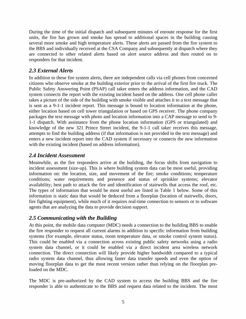
During the time of the initial dispatch and subsequent minutes of enroute response for the first units, the fire has grown and smoke has spread to additional spaces in the building causing several more smoke and high temperature alerts. These alerts are passed from the fire system to the BBS and individually received at the CSA Company and subsequently at dispatch where they are connected to other related alerts based on alert source address and then routed on to responders for that incident.
2.3 External Alerts In addition to these fire system alerts, there are independent calls via cell phones from concerned citizens who observe smoke at the building exterior prior to the arrival of the first fire truck. The Public Safety Answering Point (PSAP) call taker enters the address information, and the CAD system connects the report with the existing incident based on the address. One cell phone caller takes a picture of the side of the building with smoke visible and attaches it to a text message that is sent as a 9-1-1 incident report. This message is bound to location information at the phone, either location based on cell tower triangulation or based on GPS receiver. The phone company packages the text message with photo and location information into a CAP message to send to 9-1-1 dispatch. With assistance from the phone location information (GPS or triangulated) and knowledge of the new 321 Prince Street incident, the 9-1-1 call taker receives this message, attempts to find the building address (if that information is not provided in the text message) and enters a new incident report into the CAD system if necessary or connects the new information with the existing incident (based on address information).
2.4 Incident Assessment Meanwhile, as the fire responders arrive at the building, the focus shifts from navigation to incident assessment (size-up). This is where building system data can be most useful, providing information on: the location, size, and movement of the fire; smoke conditions; temperature conditions; water requirements and presence and status of sprinkler systems; elevator availability; best path to attack the fire and identification of stairwells that access the roof, etc. The types of information that would be most useful are listed in Table 1 below. Some of this information is static data that would be deduced from a floorplan (location of stairwells, doors, fire fighting equipment), while much of it requires real-time connection to sensors or to software agents that are analyzing the data to provide decision support.
2.5 Communicating with the Building At this point, the mobile data computer (MDC) needs a connection to the building BBS to enable the fire responder to request all current alarms in addition to specific information from building systems (for example, elevator status, room temperature data, or smoke control system status). This could be enabled via a connection across existing public safety networks using a radio system data channel, or it could be enabled via a direct incident area wireless network connection. The direct connection will likely provide higher bandwidth compared to a typical radio system data channel, thus allowing faster data transfer speeds and even the option of moving floorplan data to get the most recent version rather than relying on the floorplan pre-loaded on the MDC. The MDC is pre-authorized by the CAD system to access the building BBS and the fire responder is able to authenticate to the BBS and request data related to the incident. The most
5
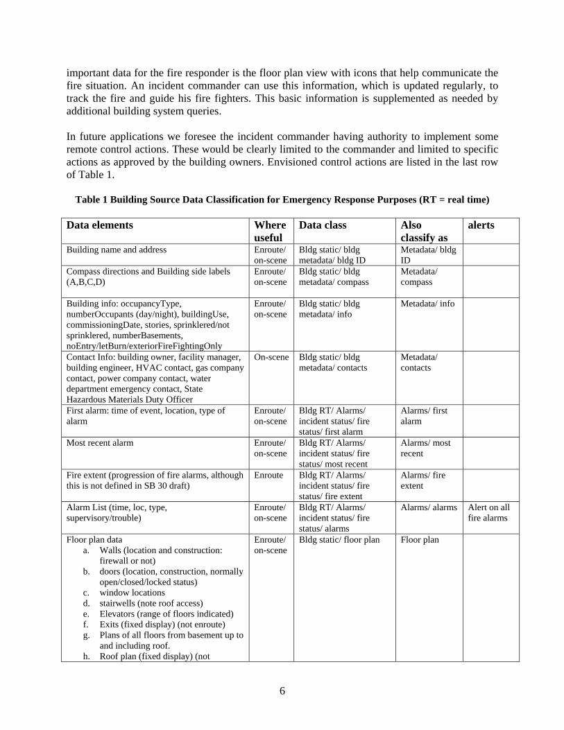
important data for the fire responder is the floor plan view with icons that help communicate the fire situation. An incident commander can use this information, which is updated regularly, to track the fire and guide his fire fighters. This basic information is supplemented as needed by additional building system queries. In future applications we foresee the incident commander having authority to implement some remote control actions. These would be clearly limited to the commander and limited to specific actions as approved by the building owners. Envisioned control actions are listed in the last row of Table 1.
Table 1 Building Source Data Classification for Emergency Response Purposes (RT = real time) Data elements Where
useful Data class Also
classify as alerts
Building name and address Enroute/ on-scene
Bldg static/ bldg metadata/ bldg ID
Metadata/ bldg ID
Compass directions and Building side labels (A,B,C,D)
Enroute/ on-scene
Bldg static/ bldg metadata/ compass
Metadata/ compass
Building info: occupancyType, numberOccupants (day/night), buildingUse, commissioningDate, stories, sprinklered/not sprinklered, numberBasements, noEntry/letBurn/exteriorFireFightingOnly
Enroute/ on-scene
Bldg static/ bldg metadata/ info
Metadata/ info
Contact Info: building owner, facility manager, building engineer, HVAC contact, gas company contact, power company contact, water department emergency contact, State Hazardous Materials Duty Officer
On-scene Bldg static/ bldg metadata/ contacts
Metadata/ contacts
First alarm: time of event, location, type of alarm
Enroute/ on-scene
Bldg RT/ Alarms/ incident status/ fire status/ first alarm
Alarms/ first alarm
Most recent alarm Enroute/ on-scene
Bldg RT/ Alarms/ incident status/ fire status/ most recent
Alarms/ most recent
Fire extent (progression of fire alarms, although this is not defined in SB 30 draft)
Enroute Bldg RT/ Alarms/ incident status/ fire status/ fire extent
Alarms/ fire extent
Alarm List (time, loc, type, supervisory/trouble)
Enroute/ on-scene
Bldg RT/ Alarms/ incident status/ fire status/ alarms
Alarms/ alarms Alert on all fire alarms
Floor plan data a. Walls (location and construction:
firewall or not) b. doors (location, construction, normally
open/closed/locked status) c. window locations d. stairwells (note roof access) e. Elevators (range of floors indicated) f. Exits (fixed display) (not enroute) g. Plans of all floors from basement up to
and including roof. h. Roof plan (fixed display) (not
Enroute/ on-scene
Bldg static/ floor plan Floor plan
6

enroute): i. Access doors and locked/unlocked
ii. Roof construction (steel bar joist or tensioned concrete)
iii. Heavy objects (towers, generators, air handling units (AHU))
iv. Air/smoke evacuation vents Fire fighter building features (4.1), top items here are enroute/fixed/incident commander (IC)
a. Standpipes b. Firefighter connections (and optionally
areas served by each connection) c. Areas of refuge d. Firefighter elevators (also under
elevator category) e. Firefighter entrances f. Location of fire panel
Enroute/ on-scene
Bldg static / features/ fire fighter features/ enroute
Fire features/ enroute
a. Fire fighter building features, not enroute utility shutoffs i. Gas
ii. Electric iii. HVAC iv. Master sprinkler
b. Location of fixed display c. Fire phones d. Pre-positioned firefighting gear e. Air-pack refilling station f. Halon suppression system
On-scene Bldg static / features/ fire fighter features/ IC
Fire features/ IC
Building features not enroute (useful to police) a. Hazardous structures (tanks/ heavy
loads)/ materials/ material safety data sheets (MSDS) (on fixed display only)
b. Security guard location c. Video camera locations
On-scene
Bldg static / features/ fire fighter features Bldg static / features/ law enforcement features
Features/
Site features: a. Hydrants (standard, large volume) b. Access streets, driveways, parking c. Other emergency vehicle accessible
locations around building perimeter d. Egress pathways/sidewalks e. Vehicle restrictions (height, width,
weight) f. Key box location g. Triage area (optional)
Enroute/ on-scene
Building static/ site site
Sprinkler status: (flowing, trouble) Enroute/ on-scene
Bldg RT/ sprinkler Sprinkler Alert on sprinkler flowing
Building occupants (#, location, certainty) Enroute/ on-scene
Bldg RT/ occupancy sensors
occupants
Smoke control system status: on/off, summary text (e.g., “vent floor 3, pressurize stairwells”), pressure sensor list (location and pressure)
On-scene Bldg RT/ smoke ctrl Smoke ctrl Alert on ON/OFF status change
First Responder status: location, ID, qualifications, physiological condition,
On-scene First responder status Alert on man down
7

remaining time on air-pack. (alarm on man down) Elevator status (for each elevator):
a. Location, building elevator ID, floors served
b. Status (operating/disabled/ in use by fire command/ in use for evacuation
c. Alarms (if any) d. Current floor, direction of movement,
destination
On-scene Bldg RT/ elevator elevator Alert on any elevator alarm
Utility shutoffs (fixed display) a. Gas: loc, On/Off, building engineer
contact, gas company contact info b. Electric loc: On/Off, building engineer
contact, power company contact info b. HVAC: loc, On/Off, building engineer
contact c. Master sprinkler: loc, On/Off, building
engineer contact
On-scene Bldg RT/ utilities Bldg static also (except on/off)
utilities Alert on change in ON/OFF status
Fire Decision Support a. Fire heat release rate b. Visibility c. Flashover potential d. Collapse warning
On-scene Bldg RT/ fire decision support
Alert on warnings of flashover, collapse, other danger
Temperature, CO, other sensors On-scene Bldg RT/ sensors/ temp, or /CO
Sensors/ temp Alert on chem/bio
Video data On-scene Bldg RT/ video video Room info: room ID, phone numbers, use, occupant info, any local sensor data
On-scene Bldg RT/ room info
Security Info: locations of physical security alarms, security office, contact information
On-scene Bldg static/ security
Security system alarm On-scene Bldg RT/ security Alert on alarm
Lighting info: lights on/off per room On-scene Bldg RT/ lights Control functions (SB 30 section 5.3)
a. Notification appliance silence b. Fire event acknowledgement c. Fire alarm system reset d. HVAC and smoke control e. Elevator controls to override Phase 2
control and initiate Phase 1 recall of protected elevator systems
f. Gas and power shutoff g. Sprinkler shutoff h. Emergency voice communications
paging system
On-scene (not building data, just here for reference)
3. Monitoring and Sending Alerts The Building Information Services and Control System (BISACS) was developed and continues to be enhanced by NIST’s Building and Fire Research Laboratory (BFRL) as a prototype standards-based system for exchanging building information with first responders [2, 3]. The BISACS consists of a network of servers that monitor entities such as sensor devices and
8

building processes. Software processes or devices such as building sensors send alerts to the BISACS servers, and the BISACS servers propagate the information to various nodes within the BISACS network. The two main components of the BISACS network are the BISACS Base Server (BBS) and the BISACS Proxy Server (BPS). The BBS monitors and controls one or more networks and their devices while the BPS monitors other BBS or BPS. Together they collect and propagate alerts up the BISACS network hierarchy. Figure 2 depicts how a typical BBS operates to collect alerts and to control its devices. Sensors/devices are monitored and controlled by the Services Interface (SI) software component. The SI converts device signals into eXtensible Markup Language (XML) [4] formatted data that represent alerts and sends these alerts to the BBS where they are stored in a memory resident database so that they can be propagated up the network hierarchy. Any incoming requests or commands to the BBS destined for devices are passed through the BBS to the SI, and the SI translates the incoming requests or commands into signals that can be addressed and carried out by the devices.
9

BISACS Base Server (BBS) with
alerts database
Services Interface (SI)
Services Interface (SI)
Firewall Firewall
Internet
Building Network of
Devices (N)
Building Network of Devices (1)
Sends alerts and runs commands
Outgoing alerts and incoming requests and commands
Figure 2 The BISACS Base Server and Its Internal Building Networks
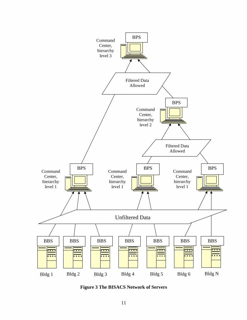
Figure 3 depicts how the BBS and the BPS are combined to form the BISACS network of servers that can monitor from a small set of buildings to a very large network of buildings. Every BPS contains all alerts from all of the nodes that are lower in the network hierarchy. This architecture can cover local buildings, to cities, to counties, to states and finally at the country level. Each jurisdiction can then be connected to the appropriate BPS for its particular monitoring requirements.
10
Bldg 1 Bldg 2 Bldg 3 Bldg 4 Bldg 5 Bldg 6 Bldg N
Command Center,
hierarchy level 1
Command Center,
hierarchy level 1
Command Center,
hierarchy level 1
Command Center,
hierarchy level 2
Command Center,
hierarchy level 3
BBS BBS BBS BBS BBS BBS
BPS
BPS BPS BPS
BPS
Unfiltered Data
Filtered Data Allowed
Filtered Data Allowed
BBS
Figure 3 The BISACS Network of Servers
11
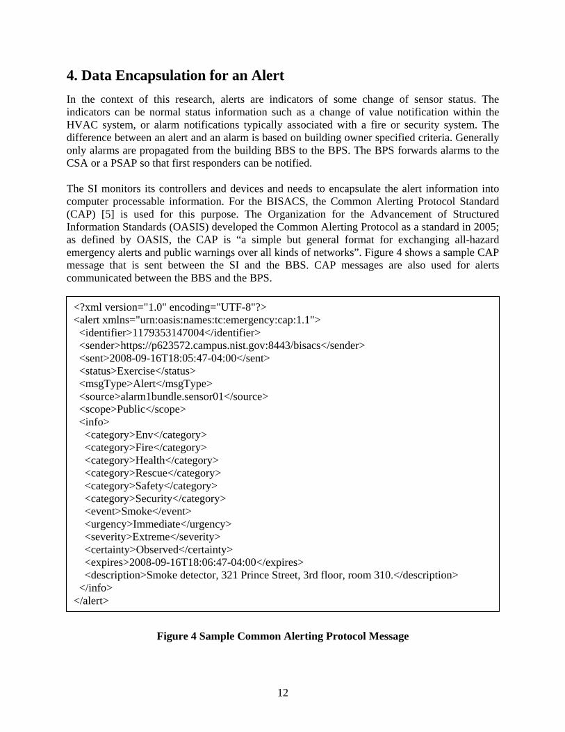
4. Data Encapsulation for an Alert In the context of this research, alerts are indicators of some change of sensor status. The indicators can be normal status information such as a change of value notification within the HVAC system, or alarm notifications typically associated with a fire or security system. The difference between an alert and an alarm is based on building owner specified criteria. Generally only alarms are propagated from the building BBS to the BPS. The BPS forwards alarms to the CSA or a PSAP so that first responders can be notified. The SI monitors its controllers and devices and needs to encapsulate the alert information into computer processable information. For the BISACS, the Common Alerting Protocol Standard (CAP) [5] is used for this purpose. The Organization for the Advancement of Structured Information Standards (OASIS) developed the Common Alerting Protocol as a standard in 2005; as defined by OASIS, the CAP is “a simple but general format for exchanging all-hazard emergency alerts and public warnings over all kinds of networks”. Figure 4 shows a sample CAP message that is sent between the SI and the BBS. CAP messages are also used for alerts communicated between the BBS and the BPS.
<?xml version="1.0" encoding="UTF-8"?> <alert xmlns="urn:oasis:names:tc:emergency:cap:1.1"> <identifier>1179353147004</identifier> <sender>https://p623572.campus.nist.gov:8443/bisacs</sender> <sent>2008-09-16T18:05:47-04:00</sent> <status>Exercise</status> <msgType>Alert</msgType> <source>alarm1bundle.sensor01</source> <scope>Public</scope> <info> <category>Env</category> <category>Fire</category> <category>Health</category> <category>Rescue</category> <category>Safety</category> <category>Security</category> <event>Smoke</event> <urgency>Immediate</urgency> <severity>Extreme</severity> <certainty>Observed</certainty> <expires>2008-09-16T18:06:47-04:00</expires> <description>Smoke detector, 321 Prince Street, 3rd floor, room 310.</description> </info> </alert>
Figure 4 Sample Common Alerting Protocol Message
12

5. Classifying and Categorizing Alerts In order to send specific alerts that have been promoted to alarm status to the first responder community, a mechanism for filtering on the alert information must be made available for this purpose. Furthermore, NIST informal reviews have shown that the amount of alert information that can be collected by the BBS can be overwhelming. The need to filter on these alerts must be developed so that the user can focus on the alerts of interest. For example, when logged into a building during an emergency to view building information, a fire fighter may not be interested in certain Heating Ventilation and Air Conditioning (HVAC) information but is interested in the information from the temperature sensors and the smoke detectors that are in alarm mode; having a mechanism for the fire fighter to filter on specific sets of alerts/alarms allows the building information to be more manageable and comprehensible. The following sections describe what is proposed to industry in order to filter on alert/alarm information.
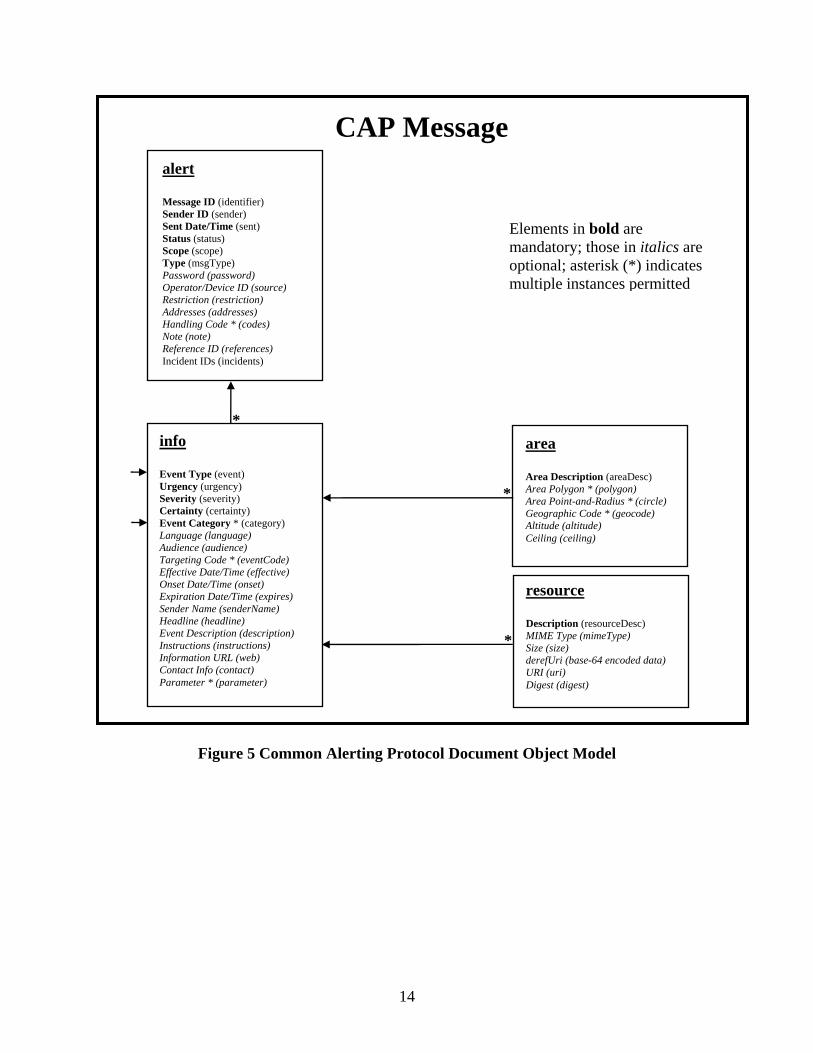
5.1 Common Alerting Protocol Message Overview Figure 5 depicts the document object model for the Common Alerting Protocol message that consists of an “alert” segment, which may contain one or more “info” segments; each “info” segment may include one or more “area” segments and may also include one or more “resource” segments. The document object model is used for implementing CAP messages using a markup language such as eXtensible Markup Language. The proposal to industry is to use the required “Event Type” element to indicate the alert event type along with the appropriate set of required “Event Category” elements to correctly map the alert event type to its category or categories. The elements of interest are noted by the arrows to the left of the “info” segment in Figure 5.
13
CAP Message
Elements in bold are mandatory; those in italics are optional; asterisk (*) indicates multiple instances permitted
info Event Type (event) Urgency (urgency) Severity (severity) Certainty (certainty) Event Category * (category) Language (language) Audience (audience) Targeting Code * (eventCode) Effective Date/Time (effective) Onset Date/Time (onset) Expiration Date/Time (expires) Sender Name (senderName) Headline (headline) Event Description (description) Instructions (instructions) Information URL (web) Contact Info (contact) Parameter * (parameter)
*
*
*
resource Description (resourceDesc) MIME Type (mimeType) Size (size) derefUri (base-64 encoded data) URI (uri) Digest (digest)
area Area Description (areaDesc) Area Polygon * (polygon) Area Point-and-Radius * (circle) Geographic Code * (geocode) Altitude (altitude) Ceiling (ceiling)
alert Message ID (identifier) Sender ID (sender) Sent Date/Time (sent) Status (status) Scope (scope) Type (msgType) Password (password) Operator/Device ID (source) Restriction (restriction) Addresses (addresses) Handling Code * (codes) Note (note) Reference ID (references) Incident IDs (incidents)
Figure 5 Common Alerting Protocol Document Object Model
14

5.2 Alert Categories The “info” segment from the Common Alerting Protocol Version 1.1 contains the required “Event Category” element (see Fig. 5); one or more of these “category” elements are used to specify the category or categories to which each alert belongs. The valid categories specified by the Common Alerting Protocol Version 1.1 [5] are listed below. Therefore, building alerts sent to first responders as CAP messages must also be classified based on these categories.
• CBRNE – Chemical, Biological, Radiological, Nuclear or High-Yield Explosive threat or attack
• Env – Pollution and other environmental • Fire – Fire suppression and rescue • Geo – Geophysical (inc. landslide) • Health – Medical and public health • Infra – Utility, telecommunication, other non-transport infrastructure • Met – Meteorological (inc. flood) • Other – Other events • Rescue – Rescue and recovery • Safety – General emergency and public safety • Security – Law enforcement, military, homeland and local/private security • Transport – Public and private transportation
5.3 Alert Event Types The “info” segment from the Common Alerting Protocol Version 1.1 contains the required “Event Type” element (see Fig. 5); this “event” element is used as “the text denoting the type of the subject event of the alert message”. The proposal to industry is to develop a standard set of event types to allow further classification of alerts for the benefit of software interpretation and filtering. The required “event” element can then be used to classify the alert event types coming from the sensor devices and/or smart agents. Within the building context, alerts come from sensor signals so the alert event types described in this section are solely based on sensor devices. All sensors respond to a limited set of inputs such as temperature, smoke and pressure, and therefore these entities can be classified by using an enumerated list of alert event types for the CAP message. Software modules that monitor sensor devices or other CAP messages and use them as input for generating their own CAP alerts are referred to as “smart agents” in this document. Smart agents typically consume raw information from devices or other alerts then formulate a different alert based on their interpretation of the events, e.g., if smoke sensors and temperature sensors indicate trends toward an alarm condition, the smart agent may interpret this trend across many sensors as an indication that a fire event is already in progress and generate a fire alert via a CAP message.
15

The following list is proposed as the list of standard alert event types for all sensors. We propose that all sensor devices or smart agents that generate CAP messages destined for various first responder communities use the key words listed below to populate their “event” element in the “info” segment of the CAP message. If the event types list for sensors and its usage are adopted by industry, then justification can be made for changes to the CAP standard to incorporate the following enumerated list of key words for the required “event” element of the “info” segment, or to create a new required element or mechanism for representing the following key words.
• Air – sensors relating to air measurements, including air velocity/wind speed/pressure/humidity and wind direction
• Biological – sensors for detecting biological hazards • Chemical – sensors for detecting hazardous chemicals • Credential – sensors for reading personal identification cards or related authentication
identifying objects, access control related devices • Electrical – sensors for detecting electronically related information such as current,
voltage, wattage, etc. • Elevator – sensors relating to elevator operation such as movement, floor indicator, etc. • Fire – sensors detecting fire, or smart agents sending alerts indicating a fire condition • Gas/Fume –sensors for gaseous entities such as radon gas, carbon monoxide gas, natural
gas, etc. • Light – sensors relating to light such as a light fixture being on or off, the light intensity
or condition, etc. • Motion – motion related sensors • Nuclear – sensors detecting nuclear detonation or hazards from nuclear power plants • Occupancy – sensors that determine the occupancy level within a room or structure,
these devices may or may not use motion sensors • Physiological – sensors such as those monitoring body temperature, heart rate, etc. • Portal – sensors for any type of entrance/exit way (door, window, gate, etc.); such as
opened/closed, locked/unlocked, jammed/broken, etc. • Radiological – sensors detecting levels of radiation • Smoke – sensors relating to smoke hazards • Sound – sound or noise level sensors • Switch/Valve – sensors for any type of switches or valves other than portals; such as
opened/closed, locked/unlocked, jammed/broken, percent opened for valves, etc. • Temperature – sensors for indoor and outdoor temperatures including heat sensors • Tremor – sensors for window/building vibration or tremors from earthquakes • Water – sensors relating to water measurements • Other – all other sensors that do not fit with any of the above event types.
5.4 Alert Event Types and Their Related Categories The first column in the following table denotes the key word(s) for classifying the alert event types that can be sent by various sensors and/or smart agents. For each alert event type, columns two through thirteen in the table indicate the corresponding category or categories to which it
16

belongs. All alerts sent using the Common Alerting Protocol must contain at least one “info” segment to describe an alert; each “info” segment must contain all related categories to the alert event type indicated in the “event” element (see Figures 4 and 5). Notice that the CAP message allows for each alert in the “info” segment to belong to one or more categories corresponding to the columns listed in Table 2. For each row, the ‘X’ characters in the columns indicate the required category or categories to which the alert event type belongs; all columns without the ‘X’ indicator are considered as optional categories. This document proposes that the key words listed in the first column of Table 2 be indicated first in the “event” element of the “info” segment followed by any optional text that may be needed to describe the event further such as event subtypes and other related descriptions. Any optional text used in the “event” element after the key words are indicated must be separated by a delimiter such as the colon character (‘:’).
Table 2 Alert Event Types and Their Categories
CAP Categories
CBRNE Env Fire Geo Health Infra Met Other Rescue Safety Security Transport Air X X X X X Biological X X X X X X X Chemical X X X X X X X Credential X Electrical X X X X X Elevator X X X X X Fire X X X X X X Gas/Fume X X X X X X X X Light X X X X X X X Motion X X X X X Nuclear X X X X X X X Occupancy X X X X Physiological X X X X X Portal X X X Radiological X X X X X X X Smoke X X X X X X Sound X X X X X Switch/Valve X X X X Temperature X X X X Tremor X X X X X X X X Water X X X X X X X
Ale
rt E
vent
Typ
es
Other X
By having a standard set of alert event types and a standard way to categorize alerts coming from buildings, the user will have a more granular filtering capability on the CAP message in order to focus on alerts of interest.
6. The Standard Access Point Getting building alerts out to the proposed BISACS servers is the first requirement. These alerts must successfully arrive at a Public Safety Answering Point (PSAP), a.k.a. 9-1-1 dispatch, which
17

will handle first responder dispatch based on received alerts. The “Introduction” section and Figure 1 described the proposed end-to-end traversal of these alerts. In order for alerts to be sent to the various public safety networks, such as the CSAN, the ESInet and the PSAP (Figure 1), there is a need to have a standard network communications interface. Having a standard alert interface for all public safety networks allows any of these entities to communicate with any of their peers that are available as part of the communication loop. Due to the many configurations that are adapted by various jurisdictions, the proposed standard interface must support communications no matter which configuration will be in used. The proposed standard network interface will be called the Standard Access Point (SAP) as shown in Figure 1. The SAP will act as the gateway to each network and its interface will be standardized. The SAP is proposed to be represented as a Web Services Interface that is properly described using the Web Services Description Language (WSDL) [6]. This interface will contain a method with an array of strings for input parameters and will return an array of strings for the result. The proposed SAP interface method would have the following signature and will perform its function as follows: String[] processRequestArray(String request[]) { // The following is pseudo code for the processing of the request array 1) First check security key at request array index 0, if it is invalid then return an error message 2) Check for a valid command at request array index 1 (e.g., addCAPAlert, addNiemMsg, etc.) 3) Process the command and populate the response array accordingly 4) Return the response array } The request string array would look as follows: request[0] - session/security key; first thing to verify before processing the command. request[1] - command; e.g., addCAPAlert, addNiemMsg, removeCAPAlert, removeNiemMsg, etc. request[2] - the payload; e.g., the actual CAP xml message, actual NIEM xml message, etc. The response string array would look as follows: response[0] - status; e.g., OK, invalidSecurityKey, unknownCommand, error, etc. response[1] - supporting text or xml message response[2] - more supporting text or xml message if needed, etc. response[3] - ... Having a Standard Access Point for all public safety networks allows any of these entities to communicate with any of their peers that are available as part of the communication loop depicted in Figure 1. Due to the many configurations that are adapted by various jurisdictions, BFRL is working with industry to develop the appropriate SAP that can support communication no matter which configuration will be in used for the communication loop.
18

7. Connecting Back to the Building Once the CAP building alerts have been routed through the various networks and end up at the PSAP, these alerts are passed on to dispatched responders through the dispatch system. As noted in the fire scenario (Section 2), the responders need a connection to the building BBS so that they can request building data for better situation awareness. There needs to be some information within a CAP alert that provides the needed information for a responder to connect back to the building. The “sender” element of the CAP message contains a Uniform Resource Locator (URL) that points back to the BISACS Base Server (BBS) that originated the CAP message (see Figure 4). An Application Specific Client (ASC) with very specific security related processing is proposed to be used for connecting back to the BBS for scenario analysis. Having a standard user interface is important so that all emergency responders will be familiar with the layout and the various function buttons when communicating with any building. NIST’s Building and Fire Research Laboratory is working with the National Electrical Manufacturers Association (NEMA) to develop a standards document (SB30) for the emergency first responder user interface. The SB30 document is included in “NFPA 72, National Fire Alarm Code” [7] and describes in detail how the user interface should look and behave. The proposed layout for this user interface may look as depicted in Figure 6. The proposed security requirement for the ASC includes using the Hypertext Transfer Protocol with Transport Layer Security [8, 9] over the Transmission Control Protocol [10] for reliable and encrypted communication. X.509 certificates [11] will be used to identify the computer/terminal being used, Personal Identity Verification cards [12, 13] will be used to authenticate the users, and user identifier and password combinations will be used for the authorization process to give out appropriate credentials [14].
19

Figure 6 The Application Specific Client User Interface The ASC should allow the emergency responder to query the building server for its current set of alerts (see Figure 7) along with building information such as floorplans, number of stories and preplan information. In Figure 6, the address field indicates the location of the BBS while the sensor’s location is actually located in building 226; this is because this particular BBS is monitoring more than one building. The complete requirements and specifications for the ASC are beyond the scope of this document.
20

Figure 7 Alert Status Screen
8. The Building Floorplan The ASC in Figure 6 shows the floorplan as a JPEG image [15], however since buildings come in many shapes and sizes, BFRL is working with industry to standardize the mechanisms for communicating building floorplan and sensor location information. Having a standard way to represent building floorplans is important because it can then be used with any of the software vendors. The vendors can use their proprietary graphics engine to convert the standard floorplan into specific images for display purposes. Having a standard user interface and a standard representation for building floorplans will shift the software vendors’ attentions to focus more on value added functions and capabilities. The standard for representing building floorplans is still being researched by industry stakeholders hence the details are beyond the scope of this document.
9. Locating a Device within the Floorplan Building alerts typically come from sensors; it follows that the location of these devices must be represented on a floorplan. Having a standard representation for a sensor’s location is important because software vendors can map the location information onto the standard floorplan discussed in Section 8. Once this mapping is accomplished, the ASC can draw attention to sensors that are in “alarm” mode such as making them blink on the floorplan. The ASC can connect back to a building server and can display its list of alerts; the user can request for more information on a specific alert such as its location on a floorplan, its current status and its current value if applicable. BFRL is working with industry to develop a standard for representing the location for sensors so that this information can be carried with the CAP messages until they reach the PSAP. The
21

standard for representing a sensor’s location is still being worked with industry and is beyond the scope of this document.
10. Conclusions The National Institute of Standards and Technology is working with industry to define alternative ways to communicate building alerts to first responders’ operations centers and mobile units via the public safety networks. This paper presented the key elements required for sending building alerts through the various public safety networks in order to reach the first responders as well as the mechanisms required to connect back to the building for emergency assessments. The framework for monitoring and sending building alerts to the first responder community was proposed via the Building Information Services and Control System (BISACS); the Common Alerting Protocol was proposed as the standard for encapsulating the alerts and their contents; a standard way to classify and to categorize the alerts so that filtering can be done on alert contents was proposed; the Standard Access Point was proposed as the standard mechanism for communicating the alerts between the various public safety networks; the Application Specific Client was proposed as the standard way to connect back to the building to assess the emergency scenarios; a standard format to represent a building floorplan was discussed and a standard mechanism to represent the location of a sensor within the standard floorplan was discussed. By working with industry to standardize these key elements, the ability to send alerts from buildings through the various public safety networks to reach the Emergency Communications Centers so that the appropriate personnel can be dispatched to the emergencies can be achieved; in turn, situational awareness for the first responders will be improved so that lives and properties can be better saved.
22

23
11. References [1] Holmberg, David G., Davis, William D., Treado, Stephen J., Reed, Kent A., Building Tactical Information System for Public Safety Officials, Intelligent Building Response (iBR), NIST Internal Report 7314, January, 2006.
[2] Vinh, Alan B., Computer-Based Monitoring for Decision Support Systems and Disaster Preparedness in Buildings, International Muti-Conference on Engineering and Technological Innovation: IMETI 2008, Orlando, FL, United States, 06/29/2008 to 07/02/2008, Vol. II, pp. 285-290, July, 2008
[3] Vinh, Alan B., Building Information Services and Control System (BISACS): Technical Documentation, Revision 1.0, NIST Internal Report 7466, November, 2007.
[4] Extensible Markup Language (XML) 1.0 (Fourth Edition), available at http://www.w3.org/TR/xml/, September, 2006.
[5] Common Alerting Protocol, v. 1.1, OASIS Standard CAP-V1.1, available at http://www.oasis-open.org/committees/download.php/15135/emergency-CAPv1.1-Corrected_DOM.pdf, October, 2005.
[6] Web Services Description Language (WSDL) Version 2.0 Part 1: Core Language, available at http://www.w3.org/TR/wsdl20/, June, 2007.
[7] HTTP Over TLS, available at http://tools.ietf.org/html/rfc2818, May, 2000.
[8] The Transport Layer Security (TLS) Protocol Version 1.1, available at http://tools.ietf.org/html/rfc4346, April, 2006.
[9] NFPA 72, National Fire Alarm Code, available at http://www.nfpa.org/freecodes/free_access_agreement.asp?id=7207, August, 2006.
[10] Transmission Control Protocol, DARPA Internet Program, Protocol Specification, available at ftp://ftp.rfc-editor.org/in-notes/rfc793.txt, September, 1981.
[11] Web Services Security, X.509 Certificate Token Profile, OASIS Standard 200401, available at http://docs.oasis-open.org/wss/2004/01/oasis-200401-wss-x509-token-profile-1.0.pdf, March, 2004.
[12] Dray, J., Guthery, S., Schwarzhoff, T., NIST Special Publication 800-73-1 Interfaces for Personal Identity Verification, National Institute of Standards and Technology, Gaithersburg, MD 20899, March, 2006.
[13] FIPS 201-1, Personal Identity Verification (PIV) of Federal Employees and Contractors, National Institute of Standards and Technology, Gaithersburg, MD 20899, March, 2006.
[14] Ritter, D., Mundt, H., Isler, B., Treado, S., Access Control in BACnet, ASHRAE Journal Article, American Society of Heating, Refrigerating and Air-Conditioning Engineers, Atlanta, GA, 2006.
[15] ISO/IEC 10918-1: Information technology – Digital compression and coding of continuous-stone still images: Requirements and guidelines, available at http://www.w3.org/Graphics/JPEG/itu-t81.pdf, September, 1992.


![Connecting Home Networks [Firecomms - Thorne]](https://static.fdocuments.us/doc/165x107/559c54c51a28aba31c8b464a/connecting-home-networks-firecomms-thorne.jpg)