Connect the Dots - BGU · Connect the Dots Number Recognition & Circle Detection Work Report Keren...
17
BEN GURION UNIVERSITY Connect the Dots Number Recognition & Circle Detection Work Report Keren shemesh 3/22/2013 Abstract: In this project, presented an computational automated method for solving the game “connect the dots” based on Connected-component labeling, correlation coefficient and circular Hough transform . the framework will also paint the different Connected-Regions in output image in random colors using Connected-component labeling.
Transcript of Connect the Dots - BGU · Connect the Dots Number Recognition & Circle Detection Work Report Keren...

BEN GURION UNIVERSITY
Connect the Dots Number Recognition & Circle Detection
Work Report
Keren shemesh
3/22/2013
Abstract: In this project, presented an computational automated method for solving the game “connect the dots” based on Connected-component labeling, correlation coefficient and circular Hough transform . the framework will also paint the different Connected-Regions in output image in random colors using Connected-component labeling.

Contents
Part I .............................................................................................................................................................. 3
Project Workflow Description ....................................................................................................................... 3
1 Introduction ...................................................................................................................................... 3
1.1 About The Game ...................................................................................................................... 3
1.2 Motivation, Goals And General Idea ....................................................................................... 3
1.3 definition of OCR...................................................................................................................... 3
1.4 definition of Hough and Circular Hough transform .............................................................. 4
2 Problem domain and Assumptions ................................................................................................ 4
3 Principles of the Algorithm ............................................................................................................. 5
4 The Application ............................................................................................................................. 11
5 Experiments and Results .............................................................................................................. 12
5.1 Successes examples ............................................................................................................... 12
5.2 Known errors ......................................................................................................................... 14
6 Discussion and Conclusions.......................................................................................................... 15
7 Future Work ................................................................................................................................... 16
8 References ...................................................................................................................................... 16
Part II ........................................................................................................................................................... 16
User Manual ................................................................................................................................................ 16
9 System Requirements ................................................................................................................... 16
10 User Guide .................................................................................................................................. 16

Part I
Project Workflow Description
1 Introduction
1.1 About The Game
Connect the dots, also known as dot to dot or join the dots is a form of puzzle containing a sequence of
numbered dots. When a line is drawn connecting the dots the outline of an object is revealed. The
puzzles frequently contain simple line art to enhance the image created or to assist in rendering a
complex section of the image. Connect the dots puzzles are generally created for children. The use of
numbers can be replaced with letters or other symbols.
1.2 Motivation, Goals And General Idea
Like many other games, Connect the dots is given to kids for education reasons, but because of its
nature, it doesn’t require more than one player and often played alone. Therefore when un supervised,
kids might make mistakes causing false understanding of the numerical system. This application can help
kids by checking their drawing with the presented solution, and suggest them for an optional coloring
for the solved image.
The application will open an existing “Connect the dots” image, detect the dot circles circular Hough
transform, isolate the components suspected to be numbers using connected-component labeling and
perform an OCR on the filtered ones, mach them together, fill the new white regions in the output
image in random colors and present/save the colored and solved image to the user.
Currently, the OCR is performed by using the same approach used to solve the correspondence problem
when performing stereopsis - by maximizing a correlation similarity measure computed using a set of
pre-defined templates.
1.3 definition of OCR
OCR is an abbreviation for Optical Character Recognition. OCR allows a machine to recognize characters through an optical mechanism. The naming OCR refers to all technologies which perform translation of scanned/captured images of text (which can be handwritten or typewritten) to a standard, machine-encoded text with the same interpretation. The purpose of an OCR system is to classify optical patterns, contained in the image, to corresponding alphanumeric or other characters. After performing OCR, a further processing can be applied to the text, such as text-to-speech and text mining. OCR is a field of research in computer vision and artificial intelligence.
1.4 definition of Hough and Circular Hough transform
The Hough transform is a feature extraction technique used in image analysis, computer vision, and digital image processing. The purpose of the technique is to find imperfect instances of objects within a certain class of shapes by a voting procedure. This voting procedure is carried out in a parameter space, from which object candidates are obtained as local maxima in a so-called accumulator space that is explicitly constructed by the algorithm for computing the Hough transform.
The classical Hough transform was concerned with the identification of lines in the image, but later the Hough transform has been extended to identifying positions of arbitrary shapes, most commonly circles or ellipses.
The Circular Hough transform can be used to determine the parameters of a circle when a number of
points that fall on the perimeter are known. A circle with radius R and center (a, b) can be described
with the parametric equations
x = a + R cos(θ)
y = b + R sin(θ)
When the angle θ sweeps through the full 360 degree range the points (x, y) trace the perimeter of a
circle. If an image contains many points, some of which fall on perimeters of circles, then the job of the
search program is to find parameter triplets (a, b, R) to describe each circle.
2 Problem domain and Assumptions
A typical input image of the game can not only contain dots circles and numbers but also additional components at all kinds of sizes and shapes therefore, a set of rules is conducted:
All dot circles are circle-shaped with radius in the range of 5 to 15 pixels – the search for smaller radiuses will increase the false-positive detection of circles in the image.
All dot circles are at approximately the same size and shape.
All dot circles are filled black – this is done to avoid false-positive detection of circles in the image.
All numbers in the picture are in the same font size.
All digits can easily be isolated as different components and extracted from the image after applying threasholding.
All digit in the same number are horizontal.
the intensity of the components seen on the image is clearly different from the intensity of the background after applying threasholding.

3 Principles of the Algorithm
The problem was devided to 6 stages:
1. First the algorithm finds all connected dots in the image, those should be filled black and
circular:
a. Finding all circles in the image (in the range of 5 to 15 pixels) using Circular Hough
Transform.
b. For each circle a bounding box the size of the Diameter’s circle is created.
c. A circle is considered a connected dot in the image if:
i. Ratio of white-pixels/pixels in the bounding box is smaller than threshold. the threshhold is calculated by:
ii. The center of the circle is black.
The function ‘displayDotCircls’ marked as comment displays the selected connected dots.
There may be false positives, but they are filtered later.
Bounding box size – circle size
Circle size
4R2 –πR2
4R2 = = 0.21 ~ 0.3 = thresh

2. At this stage, the algorithm finds all numbers in the image:
a. Extracting all connected components from the image:
b. filtering out the potential connected dots that were found on the previous stage while assuming that a connected dot is not ‘in’ a number And vice versa:
i. the component’s center is in circle bounding box – it will be filtered. ii. the circle’s center is in comp bounding box – it will be filtered.
The function ‘printSuspectesComponents’ marked as comment displays the selected connected dots.

c. assuming that all the numbers are approximately at the same font size, the components
that are not on the average height are filtered.
The function ‘printSuspectesComponents’ marked as comment displays the selected connected dots.
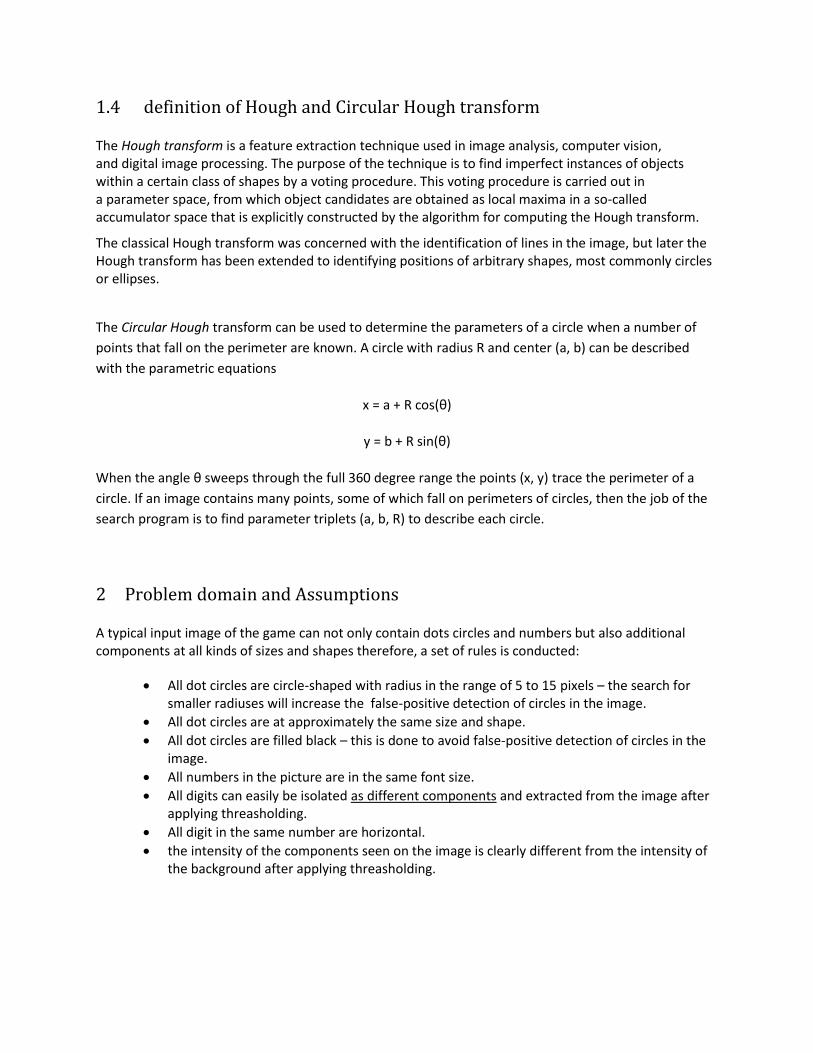
d. The components that are not on the average width (with threshold) are filtered:
The function ‘printSuspectesComponents’ marked as comment displays the selected connected dots.
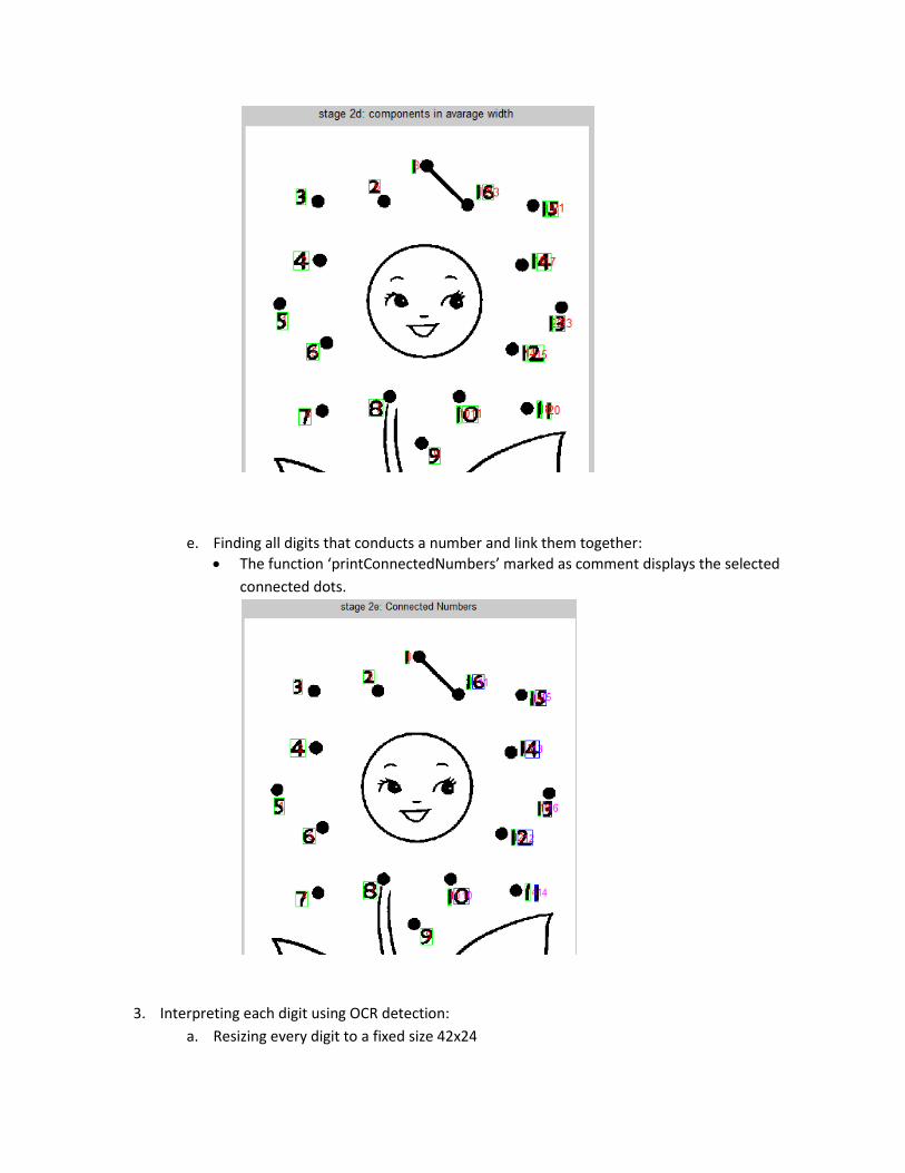
e. Finding all digits that conducts a number and link them together:
The function ‘printConnectedNumbers’ marked as comment displays the selected
connected dots.
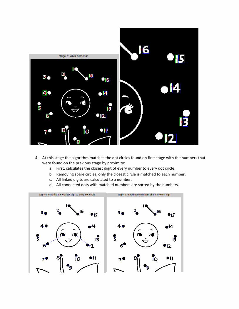
3. Interpreting each digit using OCR detection:
a. Resizing every digit to a fixed size 42x24

b. Using a pre-saved database of font templates for every number 0-9. the best fit
correspondence between a component and the database is calculated using correlation:
OCR system is implemented by using an intensity based method of establishing correspondence in the image to a pre-saved set of templates with known interpretation. 2-D correlation is chosen to measure of similarity: Given two matrices A and B of the same size, the 2-D correlation coefficient r is calculated by the
following way ( A and B represent the average values of A and BL accordingly):
The correlation coefficient ranges from -1 to 1. A value of 1 implies that a linear equation describes perfectly the relationship between A and B, with all data points lying on a line for which Bmn increases as Amn increases. A value of -1 implies that all data points lie on a line for which Bmn decreases as Amn increases. A value of 0 implies that there is no linear correlation between the variables. We can see that the expression
(Amn - A )(Bmn - B ) is positive iff Amn and Bmn lie on the same side of their respective means. Thus the correlation coefficient is positive if Amn and Bmn tend to be simultaneously greater than, or simultaneously less than, their respective means. In our case, the two matrices are:
1. A is the image on which OCR should be performed. 2. B is the template image, which represents a character or a mathematical symbol whose interpretation is known.
Moreover, in our case A and B are binary matrices Therefore, high value of a correlation coefficient means that there are a lot of pixels, lying at the same places in A and B, with same values and therefore A can get the interpretation of B (which is known). In order to use this method, a set of template images should be pre-saved. These templates serve as B matrices when computing the correlation coefficient. For this purpose, a set of templates which is supported with the application and can be found in the templates folder.
The function ‘printResult’ marked as comment displays the selected connected dots.
The function ‘extendingDB’ enables to extend the database in case the user inquire
a new set of fonts.
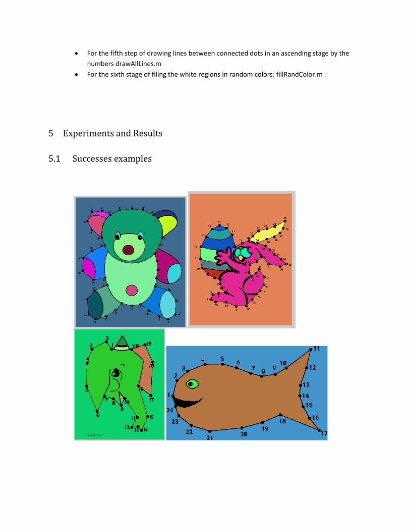
4. At this stage the algorithm matches the dot circles found on first stage with the numbers that
were found on the previous stage by proximity: a. First, calculates the closest digit of every number to every dot circle.
b. Removing spare circles, only the closest circle is matched to each number. c. All linked digits are calculated to a number. d. All connected dots with matched numbers are sorted by the numbers.

5. Drawing lines between connected dots with sequential numbers: The algorithm draws a line (paints the selected pixels in black) between the two centers using interpolation.
6. Filing the image with random numbers: a. Create the same image in RGB. b. All white connected component are found c. A random set of colors is created. d. Each color is assigned to a connected component.
4 The Application the program includes the GUI file and additional function files for the main steps in the
algorithm:
GUI file: ConnectTheDots.m
Constructing the template database letters_numbers.m – is done offline for the creation of
DB.mat – structure that contains all the tamplates.
For the first step of finding dot circles : FindDotCircls.m
For the secound step of finding numbers : findNumbers.m
for connecting the digits to a single number: FindConectedNumbers.m
For the third step of performing OCR on all digits : OCRdetection.m
for performing an OCR on a single digit: myOCR.m
For the forth step of Maching connected dots To Numbers: MachingDotsToNumbers.m
For the fifth step of drawing lines between connected dots in an ascending stage by the
numbers drawAllLines.m
For the sixth stage of filing the white regions in random colors: fillRandColor.m
5 Experiments and Results
5.1 Successes examples


5.2 Known issues
The goal of this project was to present the right result to solve the game, therefore accuracy is
important, especially when every mistake can be seen clearly.
The error can be divided to types:
False identification of number – for this case to happened, a small component, in the
approximate size of the digits in the image, is placed closer to a connected dot than the real
number.
o Performing an OCR finds the closest digit that matches therefore any component
that considered a digit, an appropriate one will be found.
Inaccurate OCR detection due to a font that is not matched by the templates database -
The application works well on characters written in fonts similar to the one of the
templates database, in case of a new font that is not similar at all to the current templates
(the database contains more than 3 fonts to every digit) there is no guarantee that the
detection will work well. – for this problem exist a function (in comment) that saves resized
templates called ‘extendDB’. When in need, the user can extend the templates database by
adding the relevant new templates to the templates folder and to the file
letters_numbers.m manually (and running it) to create a new extended database.
False identification of connected dot– for this case to happened, a component that meets
the algorithm conditions of a connected dot, is placed closer to a number than the real
connected dot.
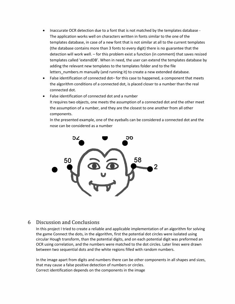
False identification of connected dot and a number
It requires two objects, one meets the assumption of a connected dot and the other meet
the assumption of a number, and they are the closest to one another from all other
components.
In the presented example, one of the eyeballs can be considered a connected dot and the
nose can be considered as a number
6 Discussion and Conclusions In this project I tried to create a reliable and applicable implementation of an algorithm for solving the game Connect the dots, in the algorithm, first the potential dot circles were isolated using circular Hough transform, than the potential digits, and on each potential digit was preformed an OCR using correlation, and the numbers were matched to the dot circles. Later lines were drawn between two sequential dots and the white regions filled with random numbers. In the image apart from digits and numbers there can be other components in all shapes and sizes, that may cause a false positive detection of numbers or circles. Correct identification depends on the components in the image
Size of the components
Proximity to others
Moreover there can be inaccurate OCR detection due to font that doesn’t correlate to the ones exist in the database.
7 Future Work A kid will be able to take picture of the game in the smartphone or tablate, and the suggested
answer will be presented to him.
8 References Here you can find references to websites containing tutorials to the technologies and tools used to create the application:
1. Mathworks official website:
http://www.mathworks.com/products/matlab/
2. “Introduction to Computational and Biological Vision”: course homepage:
http://www.cs.bgu.ac.il/~ben-shahar/Teaching/Computational-Vision//index.php
especially on course lecture Notes:
” 3D Shape and Depth Inference IV - Stereopsis”
“Perceptual Organization I - Edge aggregation case study”
3. Wikipedia, A free web encyclopedia: http://en.wikipedia.org/wiki/Main_Page.
Part II
User Manual
9 System Requirements
The application was tested on a 64 bit machine with a Windows 7 operating system and MATLAB 2012b
installed.
10 User Guide The user interface consists of one frame:
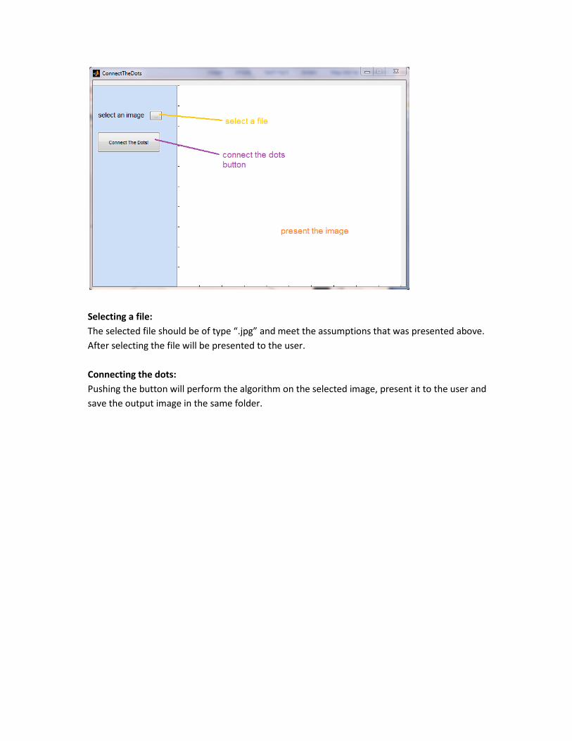
Selecting a file:
The selected file should be of type “.jpg” and meet the assumptions that was presented above.
After selecting the file will be presented to the user.
Connecting the dots:
Pushing the button will perform the algorithm on the selected image, present it to the user and
save the output image in the same folder.