Conformal Coatings: Taming the Factory Demons Coatings: Taming the Factory Demons IPC/SMTA Chapter...
113
Conformal Coatings: Taming the Factory Demons IPC/SMTA Chapter Meeting May 2014 Jason Keeping, Celestica Doug Pauls, Rockwell Collins 1
Transcript of Conformal Coatings: Taming the Factory Demons Coatings: Taming the Factory Demons IPC/SMTA Chapter...

Conformal Coatings:
Taming the Factory Demons
IPC/SMTA Chapter Meeting
May 2014
Jason Keeping, Celestica
Doug Pauls, Rockwell Collins
1

• What makes for a Bad/Ineffective Instructor?
– Irrelevant material
– Sage on the Stage complex
– Boring / monotone / ignores class
– Does not engage class
• What makes for a Bad/Ineffective Student?
– Cell phones / portable electronic devices
– Side conversations
– Snoozing
• Your instructors will strive to be good instructors; you strive to
be good students
• Will have breaks – the head cannot absorb more than the butt
can withstand
Ground Rules
2

Agenda
• Design Practices
• Preparing for Conformal Coating – assemblies and facilities
• Methods of Application – pros and cons of each
• Methods of Curing – pros and cons of each
• Evaluating the Cured Film – defects and process indicators
– New definitions being pursued for J-STD-001 and IPC-A-610
• Process Control Items
• Present Industry Research
• General Discussion
3
DESIGNING FOR CONFORMAL
COATING (DfCC)
4

Components Not Normally Coated
• Electromechanical
components (e.g. actuators.)
• Components sensitive to the
additional capacitance of
conformal coat (e.g. RF filters)
• Mating sockets, pins, test
points, grounding points
• Connectors
• Potentiometers and variable
capacitors
• Photodiodes, sensors, and
other optical devices
• Open (unsealed) components
(e.g. switches and relays)
• Batteries
5
• RF Boards (dielectrics)
• Flex part of rigid flex
• Mounting surfaces and mounting
hardware
• Displays
• Windows of programmable devices
• Spacers and fasteners
• Wires for stress relief
• EMI shields
• Mounting holes
• Components stressed by coating
(e.g. glass bodied diodes)

• Moisture / Temperature Ratings
– Leaded to Lead Free Requirements
– Baking Requirements (Moisture removal)
• Sealed vs. Unsealed Components
– Tolerances
– Remedial approaches (sealants)
Component Issues
6

7
SEDRP 2213 - Tin Whisker Mitigating Composite
Coating Project
• Requires no operator “interpretation”
• Drawing should indicate where coating MUST go
• Drawing should indicate where coating MUST NOT go
(keep out zones)
• Drawing should indicate the tolerance in the keep out
zones
• The quality system used should indicate what is to be
done when coating falls within the tolerance area of a
keep out zone
What Constitutes a Good Drawing
8
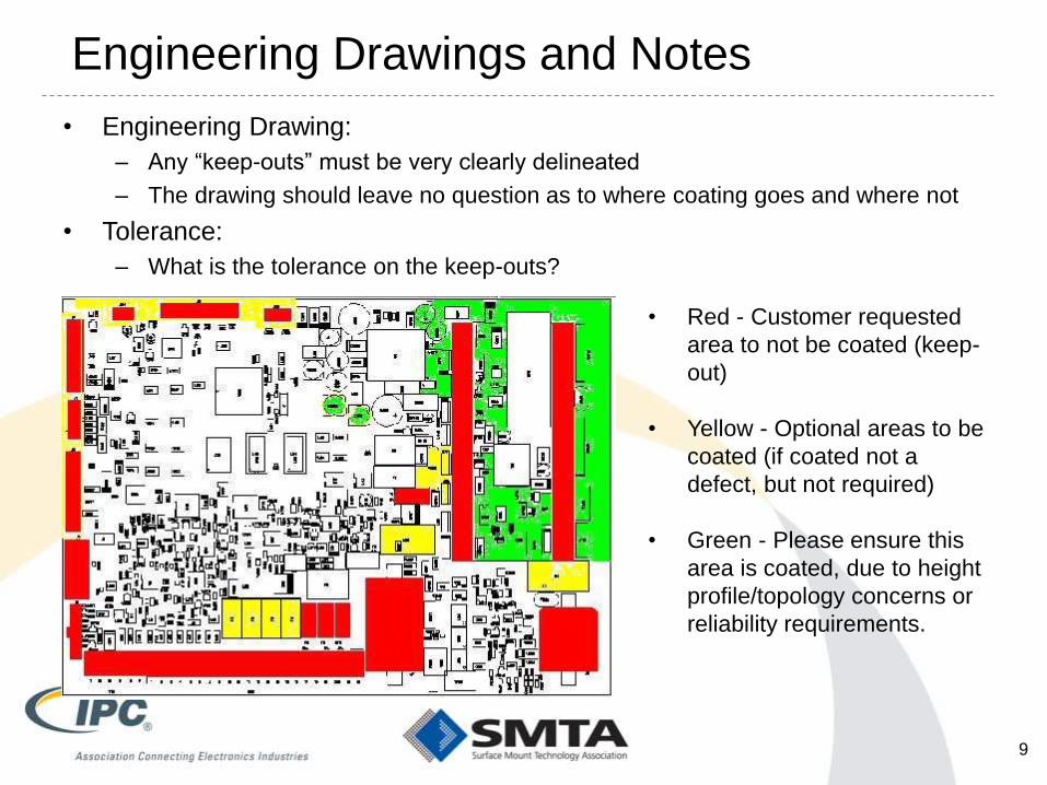
Engineering Drawings and Notes
• Engineering Drawing:
– Any “keep-outs” must be very clearly delineated
– The drawing should leave no question as to where coating goes and where not
• Tolerance:
– What is the tolerance on the keep-outs?
9
• Red - Customer requested
area to not be coated (keep-
out)
• Yellow - Optional areas to be
coated (if coated not a
defect, but not required)
• Green - Please ensure this
area is coated, due to height
profile/topology concerns or
reliability requirements.
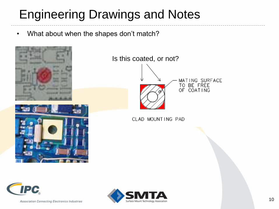
Engineering Drawings and Notes
• What about when the shapes don’t match?
10
Is this coated, or not?

Engineering Drawings and Notes
11
The Engineering Drawing The Reality When
Components Added

Engineering Drawings and Notes
• Coverage: 2D vs. 3D
12

Engineering Notes
• Designers Can Be Confusing
• On one drawing can have three different meanings for cross-hatching
• Z-Height restrictions, Segregation Zones, coating keep outs
• Agreement between customer, user and contractor need to be up-front on
definition of coverage.
• is coating required on the sides of metallic locations
• is coating required on the sides of hermetically sealed locations
• is coating required below/beneath components
• is coating required on the backside of leads
• Engineering drawings may list cure notes.
• These notes need to be confirmed per material, process and thickness of
the application that is applied. (Select, Dip, Spray)
• In general, don’t let your design engineers use Engineering Notes to
define the manufacturing process
13
Break #1 – 10 minutes
'Whoever said the pen is mightier than the sword, obviously never
encountered automatic weapons.' General MacArthur
Apache Longbow
14

FACILITIES CONSIDERATIONS
15
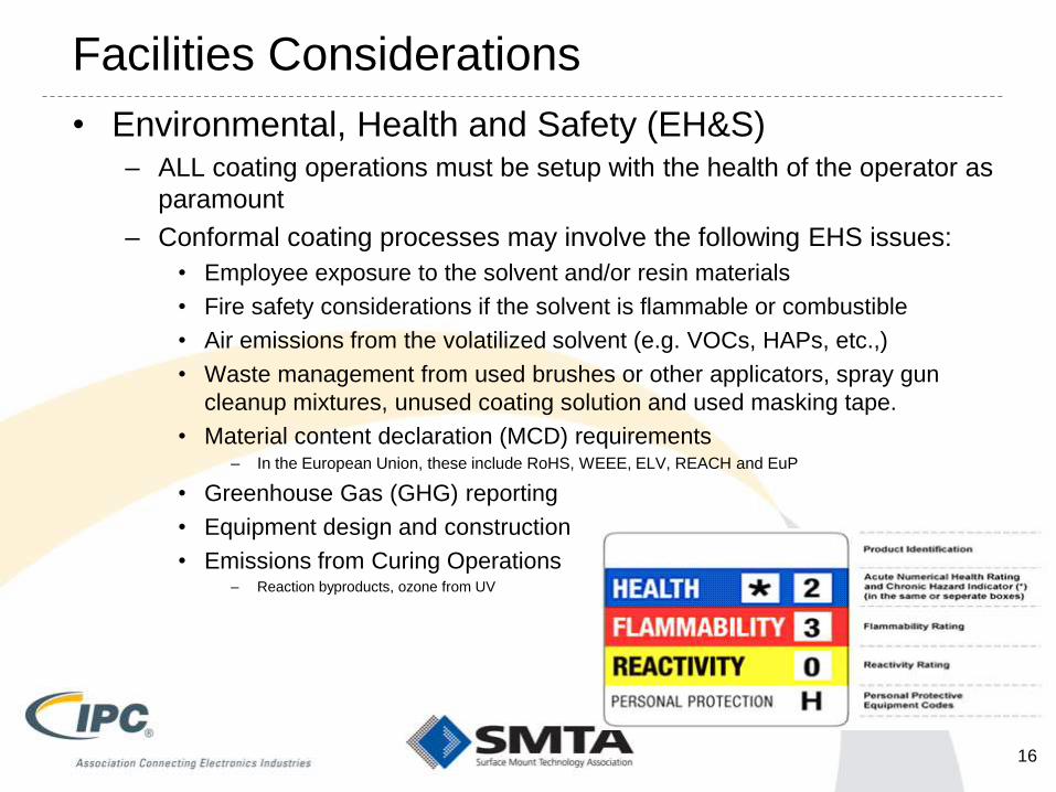
Facilities Considerations
• Environmental, Health and Safety (EH&S) – ALL coating operations must be setup with the health of the operator as
paramount
– Conformal coating processes may involve the following EHS issues:
• Employee exposure to the solvent and/or resin materials
• Fire safety considerations if the solvent is flammable or combustible
• Air emissions from the volatilized solvent (e.g. VOCs, HAPs, etc.,)
• Waste management from used brushes or other applicators, spray gun
cleanup mixtures, unused coating solution and used masking tape.
• Material content declaration (MCD) requirements – In the European Union, these include RoHS, WEEE, ELV, REACH and EuP
• Greenhouse Gas (GHG) reporting
• Equipment design and construction
• Emissions from Curing Operations – Reaction byproducts, ozone from UV
16

Facilities Considerations
• Occupational Safety and Health Administration
(OSHA) – Applying conformal coatings by spraying is subject to the
1910.107 Spray Finishing using Flammable and Combustible
Materials standard of US OSHA
– Wearing a respirator requires compliance to several US
OSHA requirements in their 1910.134 Respiratory Protection
standard including • medical clearance to wear a respirator 134(e); annual fit testing 134(f);
required training 134(k); and respirator maintenance 134(h).
– The label for each hazardous chemical that is classified shall
include the signal word, hazard statement(s), pictogram(s),
and precautionary statement(s) specified for each hazard
class and associated hazard category. • Be aware that many of these will change in the next few years due to global
harmonization laws
– Property protection insurance carrier approval, US OSHA
standard 1910.106 covers the storage and use of flammable
liquids.
17

Facilities Considerations
• EPA – Waste from conformal coating, such as
• mixture that results from cleaning the tooling
• its container of the coating last applied.
• Or unused or out-of-date coating solution.
• Such wastes are typically classified as flammable wastes (US EPA waste code D001).
– EPA definition of a flammable waste is a waste with a flash point below
140F (60C).
– Contact of a solid absorbent material (e.g. wipes) with a flammable
solvent means that the wipe material must be disposed of as a
hazardous flammable solid waste.
– Measures & regulates Greenhouse Gas (GHG) reporting
– Quantifies average CO2 emissions per KWH of electricity by zip code
• Design for the Environment (DfE)
– It may be very important to your customer that you manufacture
product in an environmentally conscious manner
18

PREPARING ASSEMBLIES
FOR COATING
19
Surface Preparation
• What is desired is a clean, dry surface, free from materials, or
surface conditions which may interfere with coating application,
cure, or adhesion.
• Cleaning Considerations (see IPC-CH-65B)
– Visual inspection criteria, component geometries, stand-off heights, non-
hermetically sealed components; component issues and residues, surface
tension and capillary forces; flux residue variability, wash chemistry types
– Visible residue (coating materials, masking materials, FOD)
– Invisible residues (silicones, oils)
• Dry
– Does not have to be “bone-dry” unless the coating requires it
• Surface Conditions
– Low surface energy on bonding surface
– Mold release agents in parts
– Effects on the solder mask from reflow processes (Sn-PB, LF)
20

Baking Prior To Coating
• Baking
– Validation methods – Know what happens in the oven
• Flow of air in ovens with and without load – how consistent
• Dripping in ovens – presence of drip plates changes air flow
– Be aware of warm-up time (might be embedded in duration)
– Separate ovens for Silicone materials
• Outgassing products cause dewetting later
• VM&P Naphtha or toluene good solvents
– Chemical Release Soldermask (over bake)
• Mold release and other such agents coming out
• Happens when SnPb process converts to a lead free process without
considering what it does to the solder mask
– Bake Vs. rebake
• Halogen free solder mask – much more hydrophilic
– Defects in underfill from outgassing
– Not sure if this same effect would happen with CC or potting
– Do you have to bake or rebake is a topic of much debate
21

Plasma Processing
• Plasma
– Mild surface etch which increases micro-roughness and can
remove (ash) low levels of surface residues
– Also serves to improve coating wetting
– Performed in a vacuum (which can affect assemblies)
– May impact more than just solder mask (components)
– Plasma Balls (localized high density plasma)
– Recommend Argon/Oxygen or Argon-Only for silver surfaces
– Select the gasses carefully
• Argon is more of a “sand blaster”
• Oxygen more of an oxidizer
• Hydrogen is a very reactive (but scary as hell)
• Surface Treatments – Primers or Coupling Agents
22
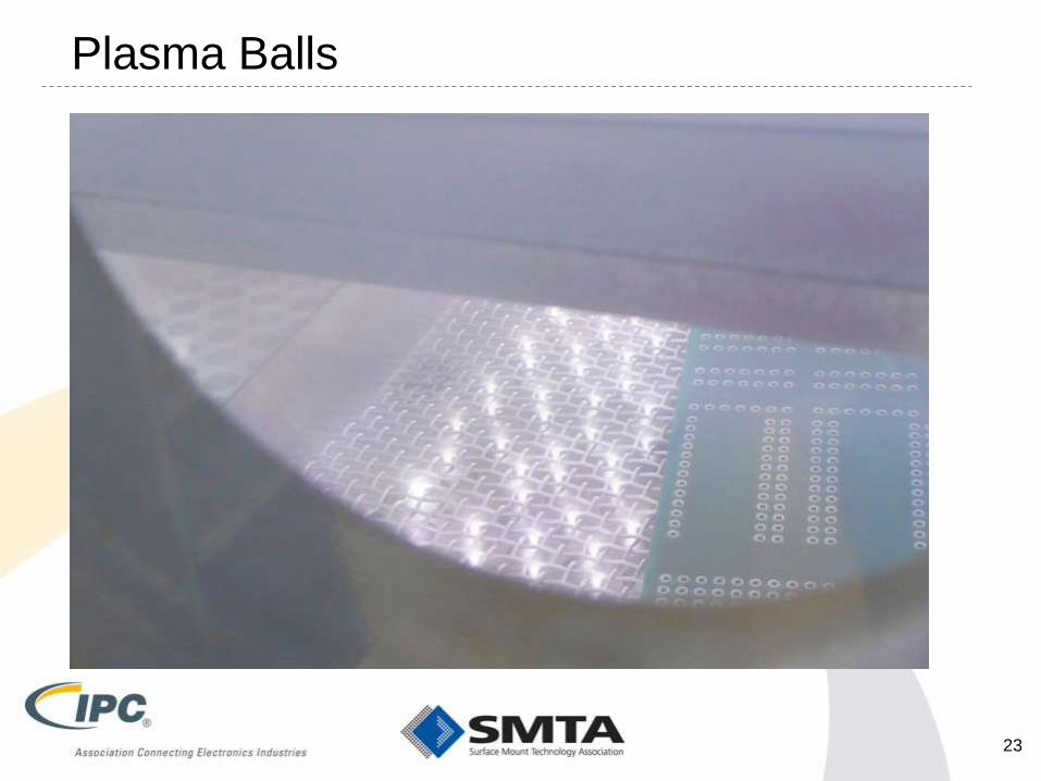
Plasma Balls
23

Handling Considerations
• Handling and Transportation Residues
– Fixtures
– Workstation Surfaces
– Popcorn Day
– Gloves
– Transport containers (totes, bags,)
– Operational procedures
– “Personal” Residues: finger salts and oils, hairs, hand creams, FOD
24

MASKING AND DEMASKING
25

Common Masking Materials
• Water Soluble Masks
– Not recommended
• Latex Peelable Masks
– Be concerned about ammonia
• Hot melt Masks
• Tapes
– Crepe masking tapes
– Polyester masking tapes
• Polymeric Plugs and Covers
– Generally quick and easy to use. Can peel accumulated coating off
• ALL masking and demasking procedures should be done under an
ionized air blower – ESD generation
• Undesirable residues often show up as contributors to either
coating dewetting during application or coating adhesion during
thermal cycling
26

Masking Aids
27

Masking - Seal and Peel
28

UV Curable Masking Compounds
• UV curable masking agents becoming more common
• Need to evaluate:
– Is it compatible with the proposed solvent system?
– Are there effects if you over-radiate the material?
– Does it leave harmful residues?
• Ion Chromatography
• SIR testing (e.g. B24 boards)
– If the material remains (e.g. under connectors) is it harmful?
29

Masking Material Selection
• There are three main streams for masking materials.
• Each of these main stream materials should be tested
for various manufacturing process outputs, such as:
– Residue from Masking Materials
– Timing (to de-mask)
– ESD Controls
– Fixturing
Level ^ Factors = 3 levels ^ 9 factors 20 thousand variations
30
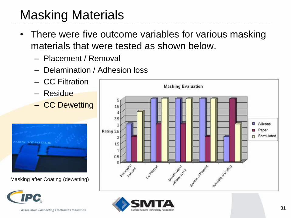
Masking Materials
• There were five outcome variables for various masking
materials that were tested as shown below.
– Placement / Removal
– Delamination / Adhesion loss
– CC Filtration
– Residue
– CC Dewetting
Masking after Coating (dewetting)
31

General Masking Requirements
1.All masking applications regardless of size must be:
• centered over required locations (with no more than 1/8”
extension beyond limits)
• having no pin or larger gaps within the material that will
allow coating leakage.
• created with complete smooth seals along all edges to
component, printed circuit board and shell surfaces and
be tear free.
2.All masking applications must be flush (thoroughly pressed)
to either component, printed circuit board or shell surfaces
unless specified otherwise prior to processing to the next step
of either Conformal Coating to aid in prevention of material
flow into undesired locations
Acceptable: Masking is smooth, completely covers
the connector & does not interfere with the near by
parts/components.
Defect: Excess masking covering near by parts or
components which call for no masking.
1. Masking Edge Connectors
Masking Standards
32

Defect: Missing masking on
required masking part/area.
Defect: Excess masking covering areas that
are not required for masking.
Acceptable: Masking
covers the entire area that
is required for masking.
Masking Standards
2. Ejectors
33
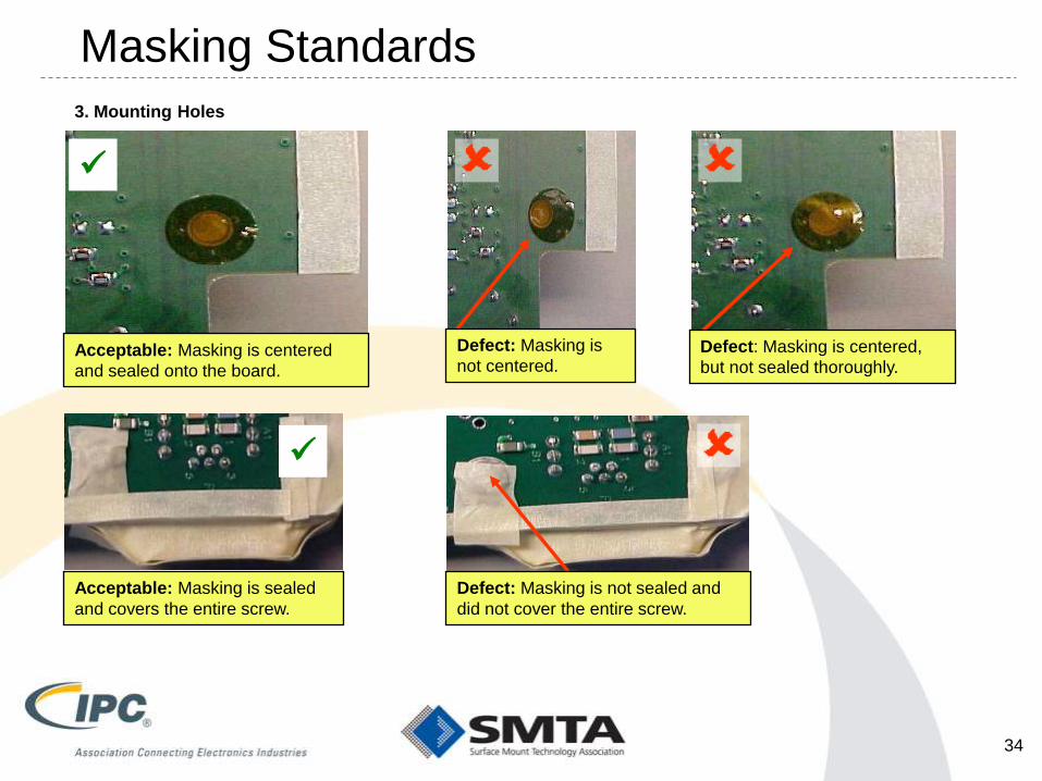
Acceptable: Masking is centered
and sealed onto the board.
Defect: Masking is
not centered. Defect: Masking is centered,
but not sealed thoroughly.
Defect: Masking is not sealed and
did not cover the entire screw.
Acceptable: Masking is sealed
and covers the entire screw.
Masking Standards
3. Mounting Holes
34
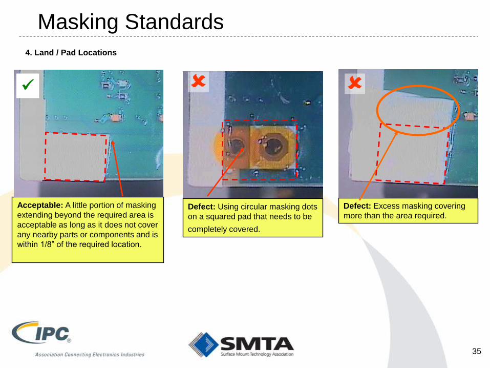
Defect: Excess masking covering
more than the area required.
Acceptable: A little portion of masking
extending beyond the required area is
acceptable as long as it does not cover
any nearby parts or components and is
within 1/8” of the required location.
Defect: Using circular masking dots
on a squared pad that needs to be
completely covered.
Masking Standards
4. Land / Pad Locations
35

Defect: Masking is not flush with
assembly board edge.
Defect: Masking covering adjacent
components.
Defect: Masking skewed or missing
from required locations.
Acceptable:
Masking is straight
and covers just the
required area.
Masking Standards
5. Assembly Sides & Edges
36

Defect: Masking is not flush with the
board surface.
Acceptable: Masking is flush with the board
surface and completely covers the connector.
Defect: Masking missing and is not
flush onto the board.
Acceptable: Masking is flush with the board
surface.
Masking Standards
6. Component body - Connectors
37
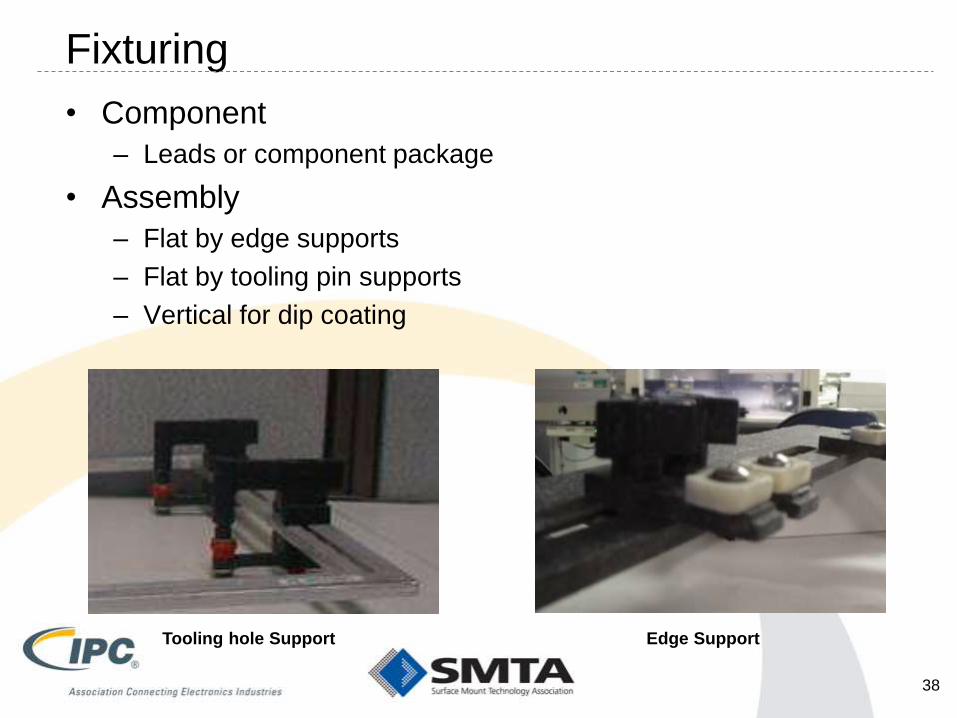
Fixturing
• Component
– Leads or component package
• Assembly
– Flat by edge supports
– Flat by tooling pin supports
– Vertical for dip coating
Edge Support Tooling hole Support
38

Masking for Parylene / Vapor Deposition
• Masking for a Vapor Deposition process is MUCH more
complicated than other methods – Must Be Gas Tight
– Highly skills and labor intensive process..!! Big cost factor
• Masking Considerations
– Need to mask more than just keep-out locations (tooling holes,
mechanical parts)
– Specific fixturing required
– Chamber maintenance
– Due to vacuum nature, all components need to be validated if
are hermetic sealed or not
– Can not use or have outgassing materials present
• May mean you have to vacuum bake prior to coating
39

Storing Prepped Assemblies Till Ready
• How do you store cleaned assemblies if there is a
significant lag between final clean and coating onset?
– Do you re-use ESD bags? If so, are they clean? Are you sure?
– Do you use ESD Totes? Do you ever clean them?
– Do you use ESD Mats? Do you ever clean them? Does the
cleaning chemical get on the assemblies?
– Do you use ESD foams to cushion boards? Are they clean?
– If left in the open (benchtop or shelves) is your environment
“clean”?
• Particulates, chemical vapors, insects, moisture
40

Demasking
• Depending on the masking process and coating used,
there are different masking techniques and issue:
– If boots or covers are used, there may be material build-up,
reducing flexibility or ability to seal, or may get FOD from flaking
– For Solvent based coatings, the material can be re-touched to
mend feathering
– Scoring may be required for higher strength materials
– Various tapes may leave residues that need to be removed
– Liquid masks may be now part of the design
– Usually has to be done with ESD controls in place (ionizers)
41
Break #2 – 10 minutes

METHODS OF APPLICATION
43
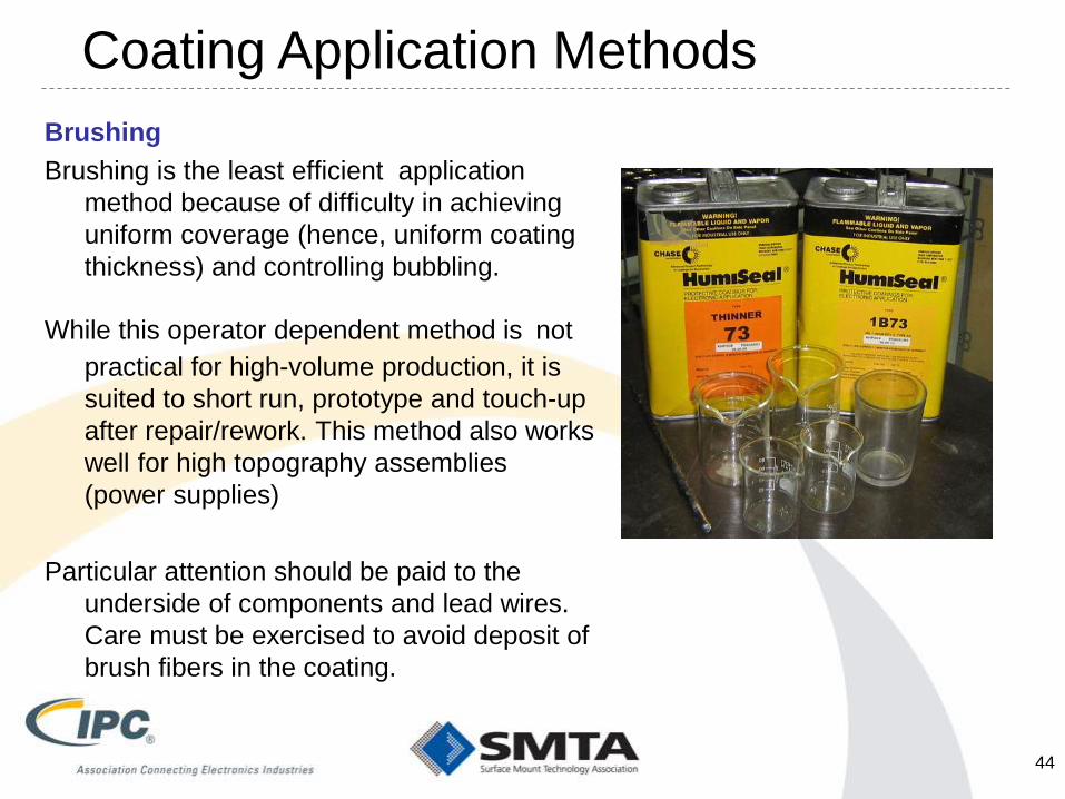
Brushing
Brushing is the least efficient application
method because of difficulty in achieving
uniform coverage (hence, uniform coating
thickness) and controlling bubbling.
While this operator dependent method is not
practical for high-volume production, it is
suited to short run, prototype and touch-up
after repair/rework. This method also works
well for high topography assemblies
(power supplies)
Particular attention should be paid to the
underside of components and lead wires.
Care must be exercised to avoid deposit of
brush fibers in the coating.
Coating Application Methods
44

Typical Workstation
45

Brushing
Advantage Disadvantage
Very simple and low start-up costs Difficult to control the material thickness
Good for low-volume high-mix production Easy to create voids and bubbles
Good for rework or touchup application Brush can be the cause of residual FOD (bristles)
Can protect against airborne FOD Operator experience dependent
Very good for small parts or for where masking
needs are onerous
Part to part variability
Tends to push a lot of coating under parts
Coating Application Methods
46

Video of Brush Coating / Syringe Coating
47

Dipping
This method, in which the masked assembly
is immersed in a tank of liquid coating
material and withdrawn, ensures uniform
coverage and predictable, repeatable film
thickness. Variables include rates of
immersion and withdrawal and viscosity of
the liquid material. The assembly should be
immersed slowly to allow the coating
material to displace the air surrounding
components, remain immersed until bubbling
has ceased, and then withdrawn. Typical
immersion and withdrawal speeds are 2 to
12 inches per minute for the first dip, with
subsequent dips made at higher speeds.
Immersion and withdrawal speeds depend
on the size and complexity of the assembly.
Timing may be manual or automated.
Coating Application Methods
48

Curtain coating
This is a way to apply material to
board. The material will continuous
fall like material curtain. Then the
conveyer will move the board pass
though that curtain. Material can
reuse in this case. But the viscosity
need to be close monitored. The
contamination of material reuse is
critical to create the defect.
Coating Application Methods
49
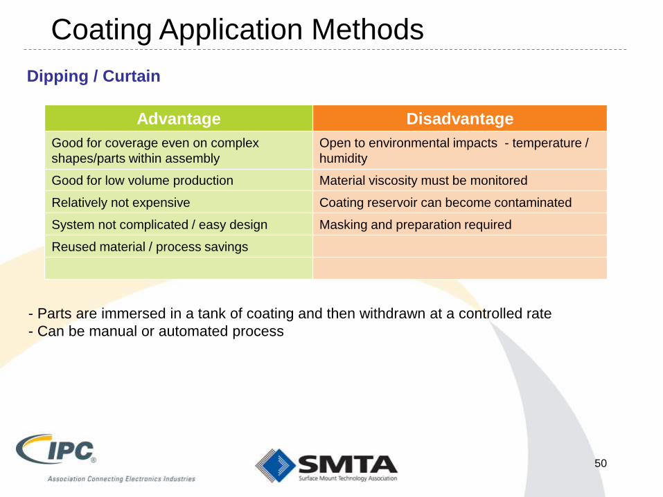
Dipping / Curtain
Advantage Disadvantage
Good for coverage even on complex
shapes/parts within assembly
Open to environmental impacts - temperature /
humidity
Good for low volume production Material viscosity must be monitored
Relatively not expensive Coating reservoir can become contaminated
System not complicated / easy design Masking and preparation required
Reused material / process savings
- Parts are immersed in a tank of coating and then withdrawn at a controlled rate
- Can be manual or automated process
Coating Application Methods
50
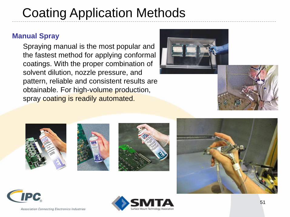
Manual Spray
Spraying manual is the most popular and
the fastest method for applying conformal
coatings. With the proper combination of
solvent dilution, nozzle pressure, and
pattern, reliable and consistent results are
obtainable. For high-volume production,
spray coating is readily automated.
Coating Application Methods
51

Manual Spray
Advantage Disadvantage
Can move the nozzle from front to
Back for better coverage
Need to contain excess over-spray or any
harmful vapors.
System not complicated Cannot control the material thickness easily
Material viscosity is very stable Material wastage / loss in process
Aerosol is good for rework Masking required to be completed
With proper training, you can coat difficult
3D assemblies
Usually much higher in VOCs as dilution is
needed for spray
Reasonable implementation cost Thin material may require multiple coat/cure
cycles to get desired thickness.
Angled spray may provide better coating
on high topography assemblies
Usually need some form of disposable backing
which can be FOD or hazardous waste
Coating Application Methods
52
Video of Manual Spray
53

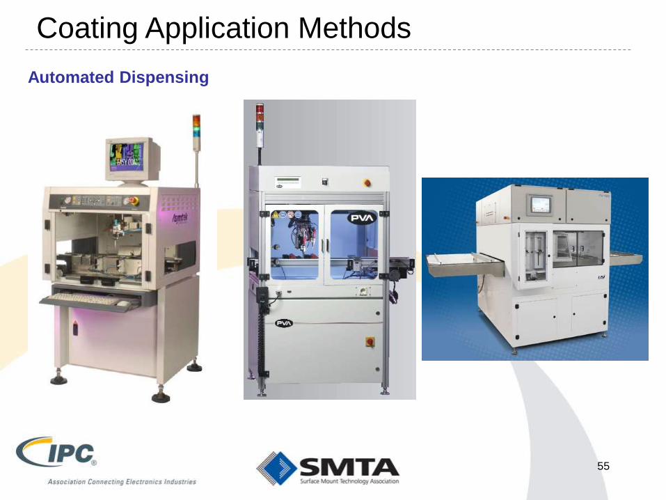
Automated Dispensing
Automated or selective coating is well
suited for high volume applications
where repeatability, speed and
efficiency are essential for success.
Selective coating use programmable
robotic X-Y-Z positioning system to
accurately manipulate the applicator
in and around the product being
coated. By using an automated
system, repeatability is introduced
and speed is greatly enhanced. With
proper programming, material waste
can be greatly reduced and in many
cases masking can be completely
eliminated.
Coating Application Methods
54
Automated Dispensing
55
Coating Application Methods
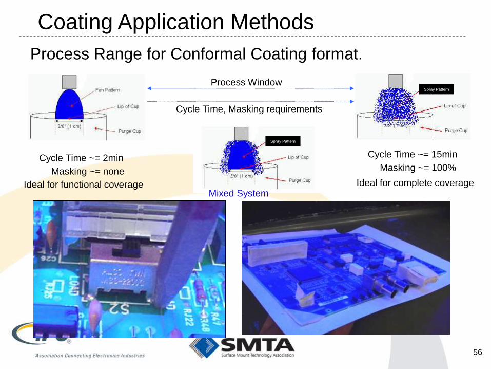
Process Range for Conformal Coating format.
Process Window
Cycle Time, Masking requirements
Cycle Time ~= 2min
Masking ~= none
Cycle Time ~= 15min
Masking ~= 100%
Ideal for functional coverage Ideal for complete coverage
Spray Pattern
Spray Pattern
Mixed System
Coating Application Methods
56

Automated (Spray) Dispensing
Nozzle/Spray Nozzle
Spray coating is usually used for to
medium to low-volume production.
Masking is required due to overspray
of nozzle design. Spray application
difficult to coat under components,
since top down view and will require
slightly more maintenance.
The type of feed system, nozzle
speed, temperature of material and
atomization pressure used will affect
the applied thickness.
Coating Application Methods
57

Automated (Spray) Dispensing
Advantage Disadvantage
Repeatable process for complete topside
surface coverage
Masking may be required
System not complicated to program Material wastage / loss in process
Process can be applied for in-line
operations with curing
Need to contain or exhaust excess over-spray
or any harmful vapors.
Cycle time greater than select application
Usually requires fixturing for repeated spray
Coating Application Methods
58

Automated (Selective) Dispensing
Nozzle/Film coating nozzle
Select coating can be used for
moderate to high-volume applications
and often eliminates the need for
masking because the material is
dispensed only on selected areas of
the circuit.
Coating thickness is affected by
material viscosity, fluid temperature,
pressures used, nozzle speed and
dispense head configuration.
Coating Application Methods
59
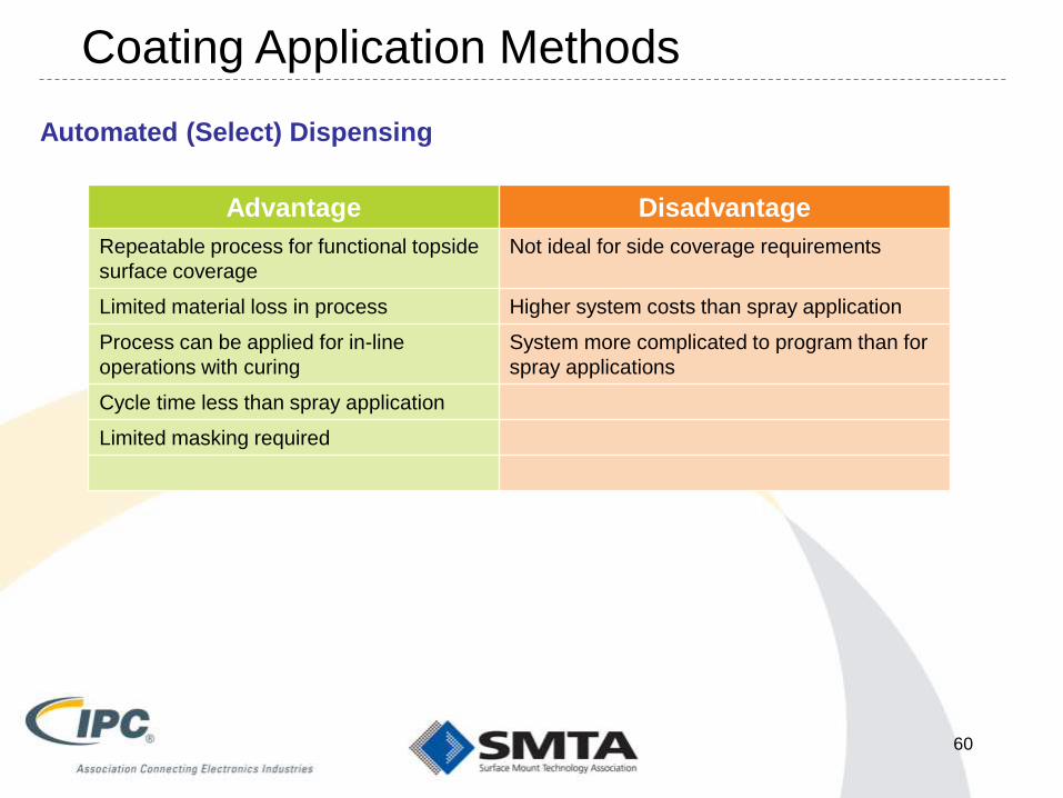
Automated (Select) Dispensing
Advantage Disadvantage
Repeatable process for functional topside
surface coverage
Not ideal for side coverage requirements
Limited material loss in process Higher system costs than spray application
Process can be applied for in-line
operations with curing
System more complicated to program than for
spray applications
Cycle time less than spray application
Limited masking required
Coating Application Methods
60

Video of Automated Spray
61
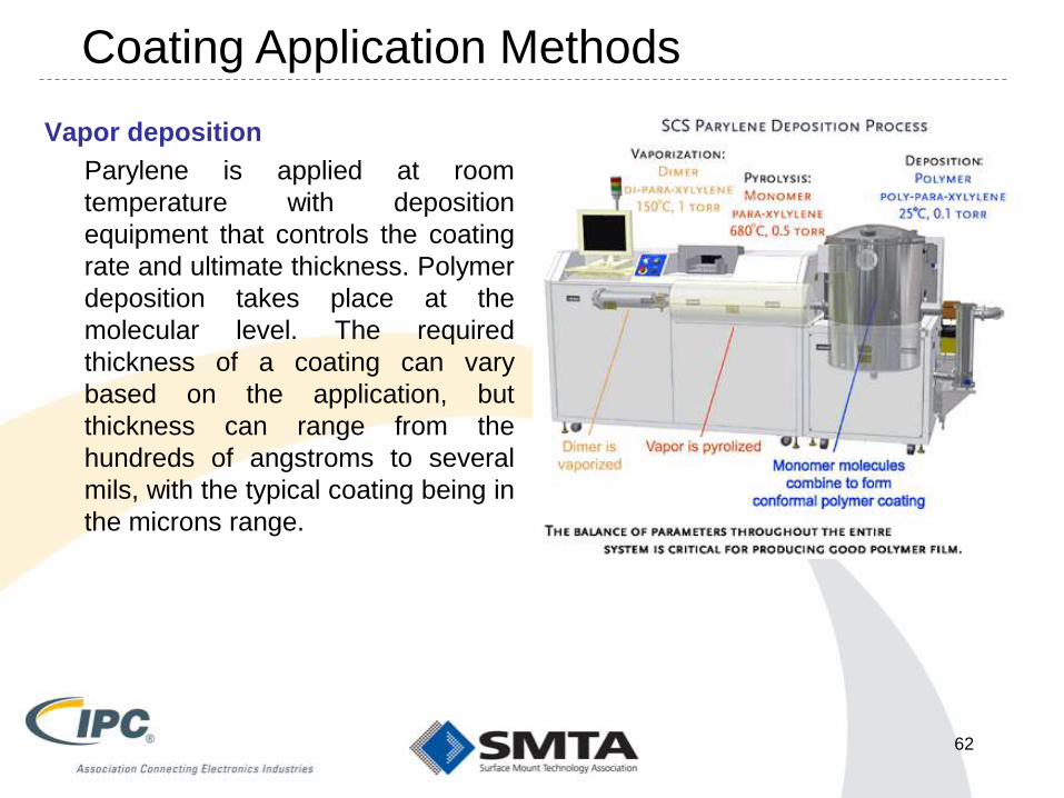
Vapor deposition
Parylene is applied at room
temperature with deposition
equipment that controls the coating
rate and ultimate thickness. Polymer
deposition takes place at the
molecular level. The required
thickness of a coating can vary
based on the application, but
thickness can range from the
hundreds of angstroms to several
mils, with the typical coating being in
the microns range.
Coating Application Methods
62

Vapor Deposition
Advantage Disadvantage
Uniform coverage on all surfaces
(component sides, lead surfaces)
Masking required to be completed
Excellent material properties Batch-mode with limited volume
No harmful vapors during process Material / Equipment expensive in cost
Requires specific processes for rework
Material thickness unknown, until after
application
Coating Application Methods
63

METHODS OF CURING
64

• Air Cure
– Solvent evaporation
– Reactive (2 part) coatings
• Thermal Curing
– Infrared lamps
– Ovens
• Standard forced air ovens
• Class A ovens
– Can be used to accelerate cure of 1 and 2 part coatings
• Ultraviolet (UV) Energy
– UV energy initiates the cure reaction
– Recommend UV coatings that have a secondary cure mechanism
Methods of Curing
65

Air Curing Advantages and Disadvantages
Advantages Disadvantages
No equipment cost Long cure process
Slower tack time allow for void release Space allocation (work in progress)
Room temp or near room temp Ventilation - coating emission
Product handling
Need to guard against airborne FOD
66

Heat Curing
Heat cure improves wetting and
lowers viscosity. Additionally for
truly rapid curing, less than 2
minutes, temperature in excess of
150°C must be used. These
temperatures may be high enough
to damage some components.
The temperature and duration time
for curing will be recommended from
manufacturer technical information.
Curing Processes
67
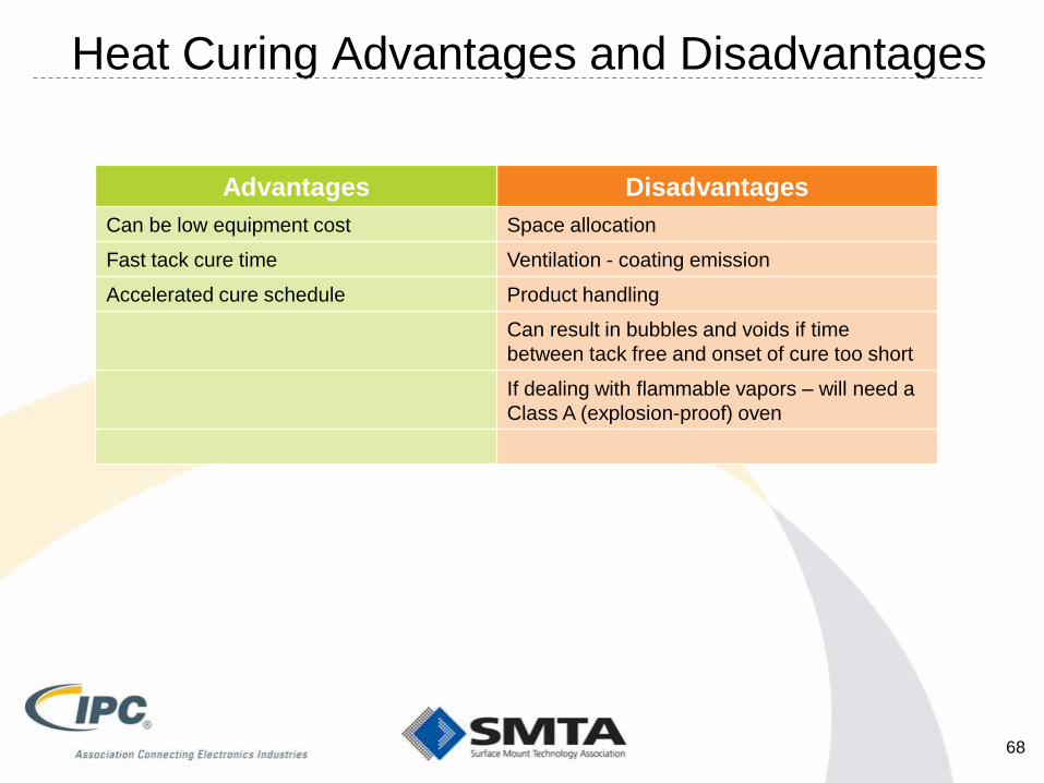
Heat Curing Advantages and Disadvantages
Advantages Disadvantages
Can be low equipment cost Space allocation
Fast tack cure time Ventilation - coating emission
Accelerated cure schedule Product handling
Can result in bubbles and voids if time
between tack free and onset of cure too short
If dealing with flammable vapors – will need a
Class A (explosion-proof) oven
68

Moisture Curing
Moisture-curing systems, a minimum of 30% relative humidity is required for
the curing areas. For this reason, plant locations in cold and dry climates
should avoid selecting conformal coating formulations, which require moisture-
cure and the associated equipment, and operating expenses of humidification.
These materials cure by using moisture in the air. On exposure to the air, the
coating will begin to cure.
Curing Processes
69

Moisture Curing Adv. & Disadvantages
Advantages Disadvantages
Minor equipment cost Need to Control humidity & temperature
Accelerated cure schedule to air cure Space allocation
Ventilation - coating emission
Degree of cure varies depending on thickness
70

UV Curing
A high mass placed suddenly into a small oven can cause overload, requiring
a prolonged time for the assembly to be brought up to specified temperature.
UV-curing ovens must be specified to meet the specific requirements for
irradiation curing of the particular material used, e.g. wavelength and energy
intensity. Issues exist with shadowing and below component area curing if
secondary curing not available within material properties.
Curing Processes
71

UV Curing Advantages and Disadvantages
Advantages Disadvantages
Very fast Shadowing – incomplete cure
Room temp or near room temp Generation of ozone from equipment
No coating emissions Intense UV light – amber glasses
May result in undesirable odors
72
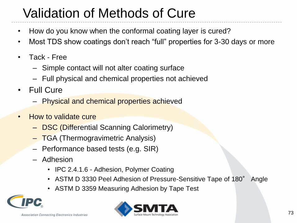
• How do you know when the conformal coating layer is cured?
• Most TDS show coatings don’t reach “full” properties for 3-30 days or more
• Tack - Free
– Simple contact will not alter coating surface
– Full physical and chemical properties not achieved
• Full Cure
– Physical and chemical properties achieved
• How to validate cure
– DSC (Differential Scanning Calorimetry)
– TGA (Thermogravimetric Analysis)
– Performance based tests (e.g. SIR)
– Adhesion
• IPC 2.4.1.6 - Adhesion, Polymer Coating
• ASTM D 3330 Peel Adhesion of Pressure-Sensitive Tape of 180° Angle
• ASTM D 3359 Measuring Adhesion by Tape Test
Validation of Methods of Cure
73

Break #3 – 10 minutes
COATING TOUCH UP AND
EVALUATING THE CURED FILM
75
Coating Touch Up Issues
• Usually cosmetic issues – a touched up area looks like a touched
up area. Will be an issue if the perception is that a coating has to
be cosmetically flawless.
• If recoating after component replacement, have to make sure area
is clean and dry, and that the replacement coating overlaps the old
coating by at least 1/8 inch
• Touch up may be done by untrained operators
76

COATING DEFECTS, CAUSES, AND
REMEDIES
(THIS GETS UGLY)
77
Good decisions come from
experience, and experience
comes from bad decisions.

• Uniformity
• Dewetting
• Fisheyes
• Inadequate coverage
• Bubbles and Voids
• Cracks and Ripples
• Orange Peel
• Delamination
• Creep Corrosion
Coating Defects and Inspection
78

What Causes This? - Uniformity
• Most release agents on components
• Localized residues (silicones, oils)
• Sharp surfaces or solder points
• Liquid based coating – gravity (solder points)
• Improper mixture of two part materials
• Variations in Surface Tension or Surface Energy
• Alloy of the component leads (reflectivity)
• Uneven coating application (e.g. brush)
• Dryness of the surface
• Do not recommend using the “blue-ness” as a measure
of thickness.
79

• Uniformity
• Dewetting
• Fisheyes
• Inadequate coverage
• Bubbles and Voids
• Cracks and Ripples
• Orange Peel
• Delamination
• Creep Corrosion
Coating Defects and Inspection
80

What Causes This? - Dewetting
• LOTS of things
• Residue on the coating surface (e.g. silicones, oils)
– Silicone rich oils from moisture cure RTV silicones
– Silicone adhesive residues wiped from assembly but not cleaned from assembly
– Residues from paintbrushes (waxes, yesterdays coating)
– Residual mold release agents on plastic components
• Liquid based coating, gravity
• Improper mixture of two part materials
• Variations in Surface Tension and Surface Energy
• Component surface finish
• Uneven coating application
• Chemical interaction between coating and coating surface
81

• Uniformity
• Dewetting
• Fisheyes
• Inadequate coverage
• Bubbles and Voids
• Cracks and Ripples
• Orange Peel
• Delamination
• Creep Corrosion
Coating Defects and Inspection
82

What Causes This? - Fisheyes
• Almost always a point contamination source
– Spot of oil or wax
– Drop of silicone rich material
– Spray coating – oil or moisture in the air line
– Contaminated coating containers
– Contaminated solvent supplies
– Contaminated mixing containers
• The point contaminant repels the coating
• Do NOT, repeat NOT, simply try to cover with more
coating
– Much like putting a band aid on an infected wound
– Clean the point contaminant with a suitable solvent
83
• Uniformity
• Dewetting
• Fisheyes
• Inadequate coverage
• Bubbles and Voids
• Cracks and Ripples
• Orange Peel
• Delamination
• Creep Corrosion
Coating Defects and Inspection
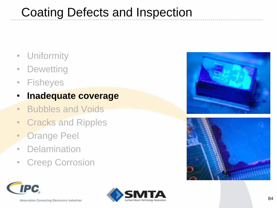
84

What Causes This? – Inadequate Coverage
• Liquid based coating, gravity
• Improper mixture of two part materials
• Surface Tension / Surface Energy
• Component surface finish
• Uneven coating application
• Residue on the coating surface
• Interaction between coating and coating surface
• Poor coating programming
• Improper fixturing
• Improper placement of assembly in coating area
• Wrong coating requirement interpretation
85
• Uniformity
• Dewetting
• Fisheyes
• Inadequate coverage
• Bubbles and Voids
• Cracks and Ripples
• Orange Peel
• Delamination
• Creep Corrosion
Coating Defects and Inspection
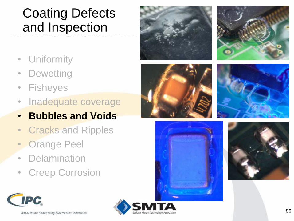
86

What Causes This? – Bubbles and Voids
• Almost all bubbles and voids are caused by entrapped solvent
trying to escape the coating
• Brush coating can entrain bubbles into the coating
• Most liquid coatings “skin over” on the top surface. Solvent must
diffuse through this layer to escape.
– Coating is too thick – takes progressively longer to diffuse
– Coating came to tack free to fast – skins over more quickly
– Coating goes into thermal cure while liquid solvent still present under
components
• Solvent responds to the heat with increased vapor pressure
• Bubbles form to relieve that pressure
– Outgassing from component/PWB (dryness)
– Outgassing from entrapment sites (plastic sleeving)
– Vacuum not strong enough (degassing)
• ESS/Test Induced
87

• Uniformity
• Dewetting
• Fisheyes
• Inadequate coverage
• Bubbles and Voids
• Cracks and Ripples
• Orange Peel
• Delamination
• Creep Corrosion
Coating Defects and Inspection
88

Coating Defects and Inspection
89
HASS Test Setup – LN2 Chamber
Effect of Freeze Spray
What Causes This? – Cracks and Ripples
• “Mudcracks”
– Arises when attempts are made to force coating to a tack free
condition too quickly
• Coating too thick (CTE related)
– Two thin coats are MUCH better than 1 thick coat
• Thermal shock – rate of change of environment greater
than the material can expand or contract
– Recommend less than 40C/min
• Improper coating mixture
• Surface energy too low – minimal adhesion
• Flexing from vibration in ESS
90

• Uniformity
• Dewetting
• Fisheyes
• Inadequate coverage
• Bubbles and Voids
• Cracks and Ripples
• Orange Peel
• Delamination
• Creep Corrosion
Coating Defects and Inspection
91

What Causes This? – Orange Peel
• Generally related to the evaporation rate of the solvent
– Local environment is too dry during application
– Improper coating mixture or solvent ratio
– Substrate is too hot
• Can sometimes arise if second coat (e.g. touchup) is
applied before the first coat is dry
• This visual effect is sometimes confused with “wrinkling”
– Too high of thermal cure or
– Too much thermal shock during plastic phase of curing
92
• Uniformity
• Dewetting
• Fisheyes
• Inadequate coverage
• Bubbles and Voids
• Cracks and Ripples
• Orange Peel
• Delamination
• Creep Corrosion
Coating Defects and Inspection
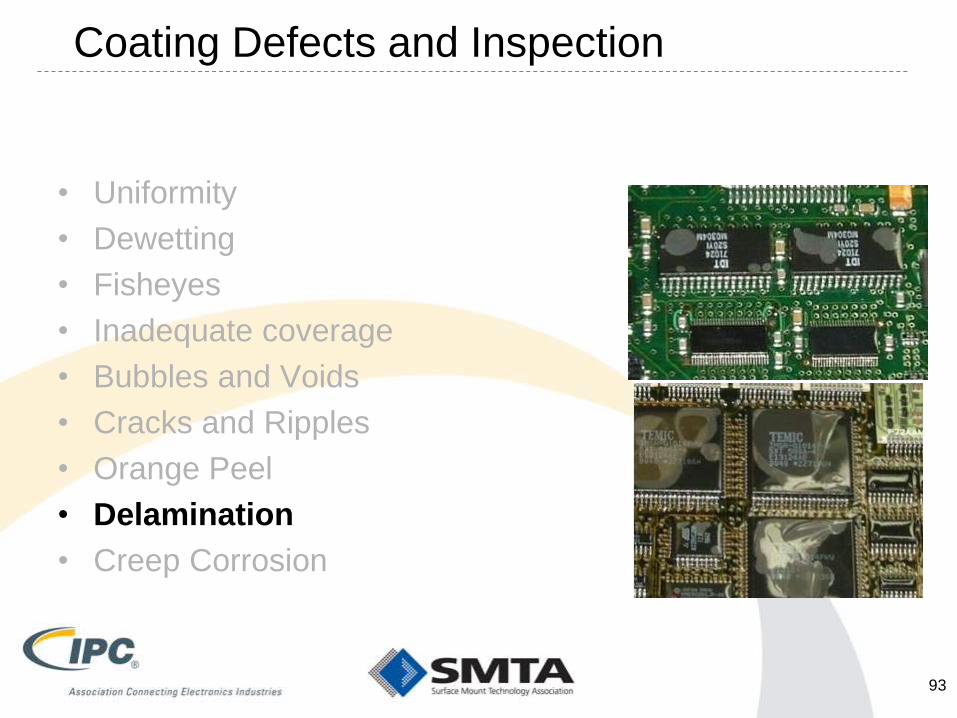
93

What Causes This? - Delamination
• Coating too thick
– Coating/laminate interface was the last to cure
• Surface energy too low
– Inherently “slick”, or from poor processing (solder mask)
• Contamination on coating surface that prevented a good
bond to the surface
• Coating not adhering to previous coating layer
• ESS testing – super hot/cold air directly impinges on
coating surface
• ESS testing – rate of change too fast (>40C/min)
• ESS testing – test extremes are beyond material bounds
• Blunt keratin at an oblique angle with variable force
applied
94

• Uniformity
• Dewetting
• Fisheyes
• Inadequate coverage
• Bubbles and Voids
• Cracks and Ripples
• Orange Peel
• Delamination
• Creep Corrosion
Coating Defects and Inspection
95
What Causes This? – Corrosive Fumes
• Creep Corrosion is the migration of corrosion products
on the surface of PCBs without bias in corrosive
environment.
– It can lead to premature failure by shorting.
• Typical causes:
– Improper application of coatings, exposed PCB regions
– Application environments trap corrosion products below coating
– Local components / materials transfer corrosive products
(below coating application)
– Local environments add surface corrosion
• Can sometimes arise if second coat (e.g. touchup) is
applied before the first coat is dry
– Materials added, migrate within coating
96
Proposed for J-STD-001 and A-610
• This is still being debated but is the only thing remaining
before going to Ballot.
• Improved definitions of what is a defect requiring
disposition and what is a process indicator
– Pretty is not a requirement, ugly is not a defect
• Quite a few submitted comments
• Areas of Contention
– General issues with Wordsmithing
– Inspection Conditions
– Bubbles
– What to do when you find a defect
97

Break – 5 min
Periodic Table of Rejected
Element Names
98
PROCESS CONTROL
(GETS UGLIER)
99

• Testing Adhesion
– Highly variable test (often depends on who does it)
• Millie the Mouse vs. Bob the Gorilla
– ASTM test is the root – “X” test and checkerboard test – tape based
• Viscosity control
– Viscosity often directly relates to thickness
• Thicker material = thicker coatings = process problems
– High vapor pressure solvents – constantly changing viscosity if left out in
the open or in a non-sealed container
– Recommend not letting operators adjust viscosity
Process Control - Adhesion
100

• Coupon Testing Method – almost everyone uses witness coupons
– Micrometers
• Can be highly variable
– Compression of coatings, operator techniques, clutch settings
– Eddy current testing
• Done on ferrous coupons, manual is highly variable, automated better
– Wet film gauge
• Wet film to dry coating correlation needs to be completed
– Both on test coupons along with production assemblies
– Ultrasonic methods
• Requires the temporary usage of a liquid gel, probe size, flat surface
– Optical methods
• Focus on the coating, then the substrate, calibrate difference
– Knowledge of refractive index for all materials required.
Measuring Coating Thickness
101
• On assemblies – almost everyone uses witness coupons
– However correlation to the actual production materials is required
• i.e. Different surface finish and topology between materials
• On assemblies
– There is no practical method for measuring coating thickness on an
assembly other than on a “flat unencumbered” area of the assembly
• Most modern assemblies are so dense this is not practical
– Most edges have connectors or components near bye
• Final users do not want new chemicals added to their process
– Especially just for process controls
– Fritz Byle, Astronautics, presented a paper on how this may be done on
an assembly with a microscope (optical method)
Measuring Coating Thickness (cont’d)
102
• Working Life
– Manual application of coatings with volatile solvents
– Recommend not letting coating operators adjust viscosity
• Tools
– Brushes (clean before first use to remove mfr residues)
– Need to be cleaned regularly with a suitable solvent
– ESD mats need to be cleaned and periodically replaced
– OSHA has many requirements on operator protection / ventilation
• Containers
– Flammable materials = suitable containers
• Wastes
– If wipes/swabs, etc. come in contact with a flammable liquid, they must be
treated as a solid flammable waste
• Handling Residues
Process Control Issues
103
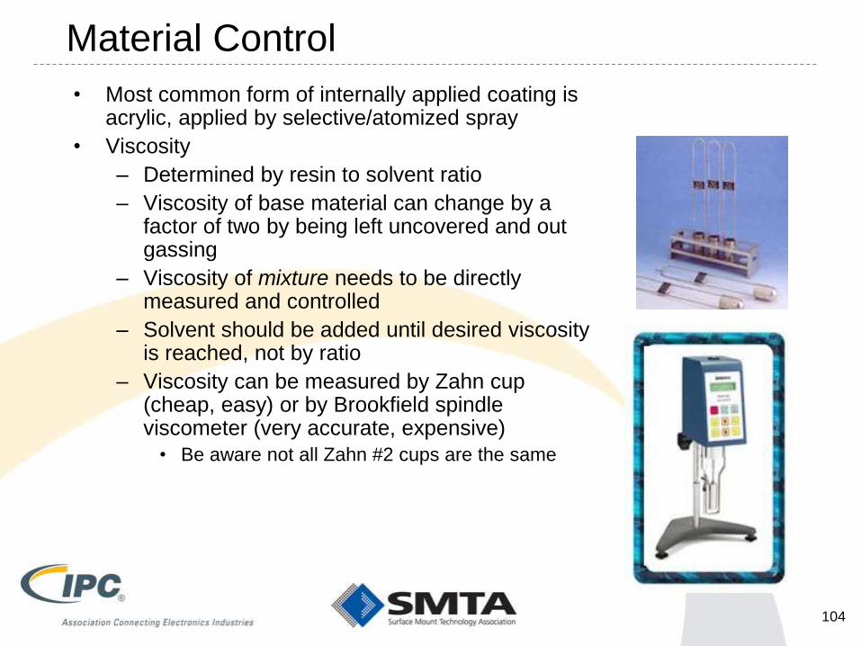
• Most common form of internally applied coating is acrylic, applied by selective/atomized spray
• Viscosity
– Determined by resin to solvent ratio
– Viscosity of base material can change by a factor of two by being left uncovered and out gassing
– Viscosity of mixture needs to be directly measured and controlled
– Solvent should be added until desired viscosity is reached, not by ratio
– Viscosity can be measured by Zahn cup (cheap, easy) or by Brookfield spindle viscometer (very accurate, expensive)
• Be aware not all Zahn #2 cups are the same
Material Control
104

• Cleanliness of area to be conformal coated is obviously a priority
• Humidity must be controlled to reduce moisture absorption and premature
drying after cleaning prior to conformal coating
• Humidity control is critical with new Halogen Free materials.
Environmental Control
105
• Key variables are head speed, head pressure, and viscosity, pot life
– Viscosity of the mixture will change over time as solvent evaporates
– Head speed and pressure determine rate of application and therefore
thickness
– All factors are interrelated
• Urethanes & Epoxies begin to polymerize quickly, resulting in shorter pot life
Coating Application
106

• Coating thickness can be controlled through direct measure or use of
coupons on either dry or wet coating material.
• Direct measurement (using micrometer/wet film gauge) is unreliable
– Surface tension results in uneven deposits
– Coating usually not fully cured when measured, can be deformed
• Apply coating to conductive coupon using same parameters:
(speed, pressure, viscosity)
Thickness Control - Mechanical
107
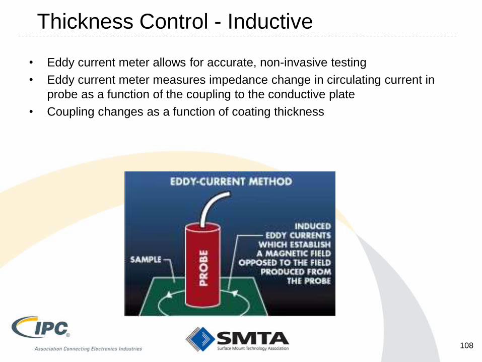
• Eddy current meter allows for accurate, non-invasive testing
• Eddy current meter measures impedance change in circulating current in
probe as a function of the coupling to the conductive plate
• Coupling changes as a function of coating thickness
Thickness Control - Inductive
108

• UV radiometers allows for accurate, non-invasive testing of the UV bulbs
• UV radiometers measure the UV exposure of the bulbs as a function of the
light intensity that is being provided
• UV Intensity changes as a function of bulb degradation
• Good fab shops use these to monitor solder mask cure operation
UV Intensity Control - Microwave
109

Industry Studies/Activities
• CC State of the Industry – Coating Coverage
– Led by Dave Hillman, Rockwell Collins for J-STD-001
• IPC-CC-830
– Revision C under way – new classes of coatings
– Possibility of MIL-I-46058 being revised
– MIR and DWV Study on new coatings
• IPC 5-33AWG Group
– Led by Jason Keeping/Doug Pauls/Fonda Wu/Amy Hagnauer
• Numerous studys on CC and Tin Whiskers
– Both CALCE and IPC host tin whisker conferences
• New IPC task group on Low Pressure Molding
• Nanocoatings

Reference Materials
• Best – participation in IPC/SMTA working groups
• IPC-HDBK-830: Revision A Published
• IPC-HDBK-850: Potting and Encapsulation
• IPC-AJ-820: Assembly and Joining Handbook
• Schutzlacke fur electronische Baugruppen – Manfred
Suppa - English version available
• UL 746 and UL94
• Electronic Materials and Processes – Harper
• Printed Circuits Handbook - Coombs
111

Your Instructors
Jason Keeping
Celestica
844 Don Mills Rd.
Toronto, Ontario M3C 1V7
Canada
416.443.7448
Doug Pauls
Rockwell Collins
400 Collins Road NE
MS 108-101
Cedar Rapids, IA 52498, USA
319.295.2109
112
Questions and Discussion
North Dakota’s First Line of Defense Against Invasion From Canada
113