Configuring Voice over IP - Cisco · Cisco AS5350 and Cisco AS5400 Universal Gateway Software...
26
CHAPTER 6-1 Cisco AS5350 and Cisco AS5400 Universal Gateway Software Configuration Guide OL-3418-02 B0 6 Configuring Voice over IP Note The information herein applies to the Cisco AS5350, Cisco AS5400, and Cisco AS5400HPX universal gateways. Note that the latter requires use of Cisco IOS release 12.2(2)XB or later. Voice over IP (VoIP) technology enables voice-capable routers and switches to transport packetized live voice traffic such as telephone calls over IP data intranetworks or internetworks rather than public switched telephone networks (PSTN) or private TDM (PBX) networks. VoIP thus enables toll bypass, remote PBX presence over WANs, unified voice and data trunking, and plain old telephone service (POTS)-Internet telephony gateways. VoIP enables more efficient and full use of your existing IP data network both, reducing transmission costs and possibly your need to support dual (voice and data) networks. Routers and switches such as the Cisco AS5350 and Cisco AS5400 universal gateways can handle origination, transport, and termination of VoIP traffic. They digitize analog voice signals, compress them, package them into a series of discrete packets, and transport them interleaved with data packets. They can transmit VoIP packets to both VoIP and non-VoIP destinations, and can receive both VoIP and nonVoIP calls. When data lines are busy, they can spill traffic onto the PSTN. To ensure acceptable quality of service (QoS) for your voice users, it is important that you configure your gateway carefully and monitor its performance vigilantly—to ensure, for voice traffic, priority service with minimal loss and delay. Unlike most other types of data, voice is intolerant of almost any form of loss or delay. Users cannot wait for a destination device to reorder packets and request that the sending device retransmit any that are missing, as it does for most other data types. To configure basic VoIP, in general you need to do the following: • Configure signaling on voice ports • Configure dial peers You might also need to do the following: • Configure voice QoS features • Configure Frame Relay for VoIP • Configure the gateway to distinguish between voice and modem calls (necessary when the network-access server supports both modem dialup and VoIP users on the same POTS interface) • Optimize dial-peer and network-interface configurations • Configure VoIP for Microsoft NetMeeting This chapter briefly introduces the subject of configuring VoIP and overviews the first few configuration tasks. It describes, at a high level, some of the voice QoS features that you can enable. Most important, it points you to other references from which you can gain a broader and deeper look at the subject.
Transcript of Configuring Voice over IP - Cisco · Cisco AS5350 and Cisco AS5400 Universal Gateway Software...

Cisco AS5350 and Cisco AS5400 UniversalOL-3418-02 B0
C H A P T E R 6
Configuring Voice over IPNote The information herein applies to the Cisco AS5350, Cisco AS5400, and Cisco AS5400HPX universal gateways. Note that the latter requires use of Cisco IOS release 12.2(2)XB or later.
Voice over IP (VoIP) technology enables voice-capable routers and switches to transport packetized live voice traffic such as telephone calls over IP data intranetworks or internetworks rather than public switched telephone networks (PSTN) or private TDM (PBX) networks. VoIP thus enables toll bypass, remote PBX presence over WANs, unified voice and data trunking, and plain old telephone service (POTS)-Internet telephony gateways. VoIP enables more efficient and full use of your existing IP data network both, reducing transmission costs and possibly your need to support dual (voice and data) networks.
Routers and switches such as the Cisco AS5350 and Cisco AS5400 universal gateways can handle origination, transport, and termination of VoIP traffic. They digitize analog voice signals, compress them, package them into a series of discrete packets, and transport them interleaved with data packets. They can transmit VoIP packets to both VoIP and non-VoIP destinations, and can receive both VoIP and nonVoIP calls. When data lines are busy, they can spill traffic onto the PSTN.
To ensure acceptable quality of service (QoS) for your voice users, it is important that you configure your gateway carefully and monitor its performance vigilantly—to ensure, for voice traffic, priority service with minimal loss and delay. Unlike most other types of data, voice is intolerant of almost any form of loss or delay. Users cannot wait for a destination device to reorder packets and request that the sending device retransmit any that are missing, as it does for most other data types.
To configure basic VoIP, in general you need to do the following:
• Configure signaling on voice ports
• Configure dial peers
You might also need to do the following:
• Configure voice QoS features
• Configure Frame Relay for VoIP
• Configure the gateway to distinguish between voice and modem calls (necessary when the network-access server supports both modem dialup and VoIP users on the same POTS interface)
• Optimize dial-peer and network-interface configurations
• Configure VoIP for Microsoft NetMeeting
This chapter briefly introduces the subject of configuring VoIP and overviews the first few configuration tasks. It describes, at a high level, some of the voice QoS features that you can enable. Most important, it points you to other references from which you can gain a broader and deeper look at the subject.
6-1 Gateway Software Configuration Guide
Chapter 6 Configuring Voice over IPVoIP Basics
Contents are as follows:
• VoIP Basics, page 6-2
• Configuring Basic VoIP, page 6-7
• Voice QoS Basics, page 6-16
• Enabling QoS Features for VoIP, page 6-17
• Additional Resources, page 6-24
Tip It is critical that you consult the additional references sited throughout and at the end of the chapter before you configure VoIP. These plus additional references throughout the Cisco website (search for configure voip to locate the most current references) provide the information that you need to optimize settings. The more information that you have at your disposal, the greater your probability of success, as measured by cost savings and user acceptance.
Note Although VoIP technology is primarily software-based, it requires that you install a universal port card into the appropriate slot of your Cisco AS5350 or Cisco AS5400 universal gateway. The number of ports or channels available for sending VoIP data depends on the capacity of your card. For more information, see Chapter 5, “Managing and Troubleshooting the Universal Port Card.”
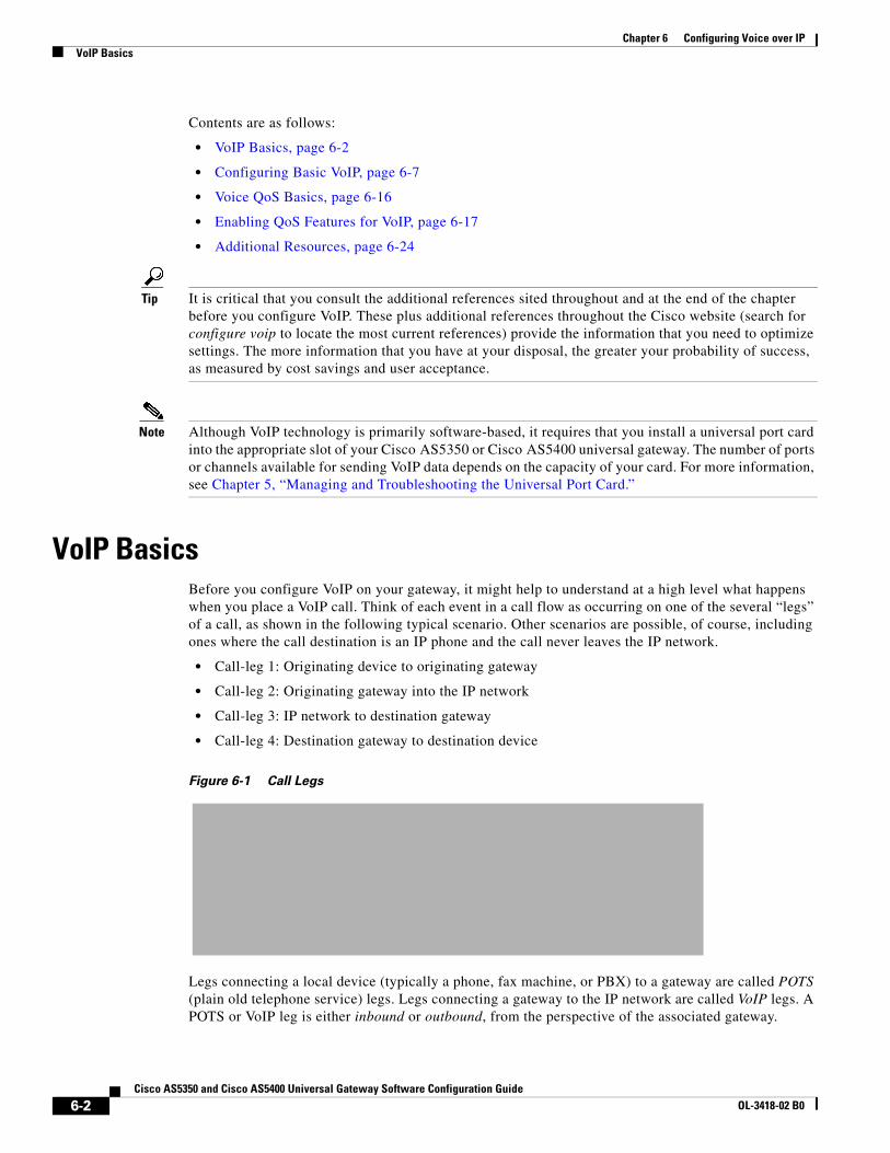
VoIP BasicsBefore you configure VoIP on your gateway, it might help to understand at a high level what happens when you place a VoIP call. Think of each event in a call flow as occurring on one of the several “legs” of a call, as shown in the following typical scenario. Other scenarios are possible, of course, including ones where the call destination is an IP phone and the call never leaves the IP network.
• Call-leg 1: Originating device to originating gateway
• Call-leg 2: Originating gateway into the IP network
• Call-leg 3: IP network to destination gateway
• Call-leg 4: Destination gateway to destination device
Figure 6-1 Call Legs
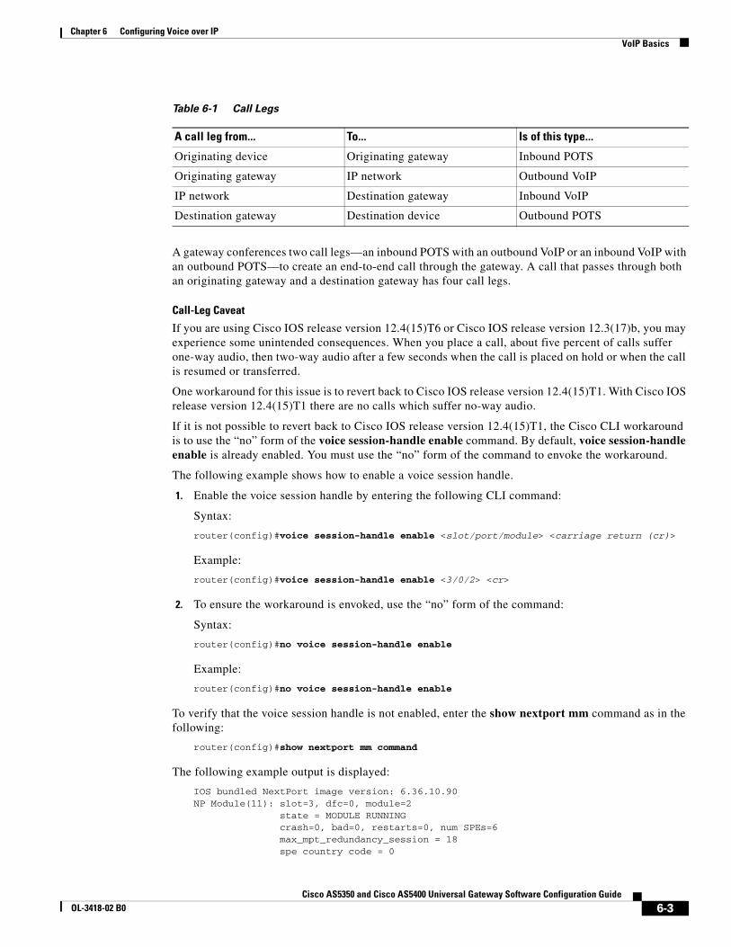
Legs connecting a local device (typically a phone, fax machine, or PBX) to a gateway are called POTS (plain old telephone service) legs. Legs connecting a gateway to the IP network are called VoIP legs. A POTS or VoIP leg is either inbound or outbound, from the perspective of the associated gateway.
6-2Cisco AS5350 and Cisco AS5400 Universal Gateway Software Configuration Guide
OL-3418-02 B0
Chapter 6 Configuring Voice over IPVoIP Basics
A gateway conferences two call legs—an inbound POTS with an outbound VoIP or an inbound VoIP with an outbound POTS—to create an end-to-end call through the gateway. A call that passes through both an originating gateway and a destination gateway has four call legs.
Call-Leg Caveat
If you are using Cisco IOS release version 12.4(15)T6 or Cisco IOS release version 12.3(17)b, you may experience some unintended consequences. When you place a call, about five percent of calls suffer one-way audio, then two-way audio after a few seconds when the call is placed on hold or when the call is resumed or transferred.
One workaround for this issue is to revert back to Cisco IOS release version 12.4(15)T1. With Cisco IOS release version 12.4(15)T1 there are no calls which suffer no-way audio.
If it is not possible to revert back to Cisco IOS release version 12.4(15)T1, the Cisco CLI workaround is to use the “no” form of the voice session-handle enable command. By default, voice session-handle enable is already enabled. You must use the “no” form of the command to envoke the workaround.
The following example shows how to enable a voice session handle.
1. Enable the voice session handle by entering the following CLI command:
Syntax:
router(config)#voice session-handle enable <slot/port/module> <carriage return (cr)>
Example:
router(config)#voice session-handle enable <3/0/2> <cr>
2. To ensure the workaround is envoked, use the “no” form of the command:
Syntax:
router(config)#no voice session-handle enable
Example:
router(config)#no voice session-handle enable
To verify that the voice session handle is not enabled, enter the show nextport mm command as in the following:
router(config)#show nextport mm command
The following example output is displayed:
IOS bundled NextPort image version: 6.36.10.90NP Module(11): slot=3, dfc=0, module=2 state = MODULE RUNNING crash=0, bad=0, restarts=0, num SPEs=6 max_mpt_redundancy_session = 18 spe country code = 0
Table 6-1 Call Legs
A call leg from... To... Is of this type...
Originating device Originating gateway Inbound POTS
Originating gateway IP network Outbound VoIP
IP network Destination gateway Inbound VoIP
Destination gateway Destination device Outbound POTS
6-3Cisco AS5350 and Cisco AS5400 Universal Gateway Software Configuration Guide
OL-3418-02 B0
Chapter 6 Configuring Voice over IPVoIP Basics
session handle enable = TRUE
If the example output comes back with the following, the “no” form of the command is not envoked:
session handle enable = FALSE
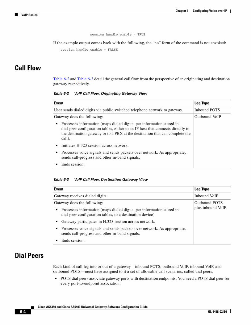
Call FlowTable 6-2 and Table 6-3 detail the general call flow from the perspective of an originating and destination gateway respectively.
Dial PeersEach kind of call leg into or out of a gateway—inbound POTS, outbound VoIP, inbound VoIP, and outbound POTS—must have assigned to it a set of allowable call scenarios, called dial peers.
• POTS dial peers associate gateway ports with destination endpoints. You need a POTS dial peer for every port-to-endpoint association.
Table 6-2 VoIP Call Flow, Originating Gateway View
Event Leg Type
User sends dialed digits via public switched telephone network to gateway. Inbound POTS
Gateway does the following:
• Processes information (maps dialed digits, per information stored in dial-peer configuration tables, either to an IP host that connects directly to the destination gateway or to a PBX at the destination that can complete the call).
• Initiates H.323 session across network.
• Processes voice signals and sends packets over network. As appropriate, sends call-progress and other in-band signals.
• Ends session.
Outbound VoIP
Table 6-3 VoIP Call Flow, Destination Gateway View
Event Leg Type
Gateway receives dialed digits. Inbound VoIP
Gateway does the following:
• Processes information (maps dialed digits, per information stored in dial-peer configuration tables, to a destination device).
• Gateway participates in H.323 session across network.
• Processes voice signals and sends packets over network. As appropriate, sends call-progress and other in-band signals.
• Ends session.
Outbound POTS plus inbound VoIP
6-4Cisco AS5350 and Cisco AS5400 Universal Gateway Software Configuration Guide
OL-3418-02 B0
Chapter 6 Configuring Voice over IPVoIP Basics
• VoIP dial peers associate destination phone numbers with IP addresses or other means to send packets to that destination. You need a VoIP dial peer for every set of destination endpoints.
A dial peer is, essentially, a single static route within a routing table. A collection of dial peers constitutes a dial plan.
Syntax
A POTS dial peer has the following syntax:
dial-peer voice tag potsdestination-pattern numberport port#other configurable options
where tag is a numeric value of local significance only, number is the full E.164 phone number of the associated endpoint, and port# is the voice port in the gateway through which the call is transmitted once a destination pattern is matched.
A VoIP dial peer has the following syntax:
dial-peer voice tag voipdestination-pattern numbersession target data addressother configurable options
where tag is a numeric value of local significance only, number is the full E.164 phone number of the associated endpoint, and data address is where the gateway sends a call whose destination pattern matches the one in the peer.
Matching Rules
A gateway redirects an incoming call along the most appropriate outbound leg. It selects the most appropriate leg by first finding the POTS or VoIP (depending on call direction) dial peer whose destination pattern matches the call’s dialed digits. For outbound VoIP legs, it chooses the longest matching dial peer. If more than one such match exists, it checks whether preferences have been assigned those peers and selects the peer with the lowest preference level.
6-5Cisco AS5350 and Cisco AS5400 Universal Gateway Software Configuration Guide
OL-3418-02 B0
Chapter 6 Configuring Voice over IPVoIP Basics
Example
Let us say, for a very simple example (your implementation will be far more complex), that a company has offices in San Jose and Newark. Extensions in the San Jose office are in the range 5000 to 5999, those in the Newark office in the range 6000 to 6999. A caller at San Jose extension 5000 wants to call Newark extension 6000. The following dial peers are needed to make this connection:
When the San Jose caller at extension 5000 dials the digits 6000, the originating gateway in San Jose does the following:
1. Receives, through port 1/0:1 to which extension 5000 connects, the dialed digits 6000.
2. Searches its VoIP dial peers until it finds dial-peer 2, whose destination pattern best matches the dialed digits.
3. Sends the dialed digits through the IP network to the gateway specified by dial-peer 2’s session target (172.16.1.1).
The destination gateway in Newark now does the following:
1. Receives the dialed digits through the IP network.
2. Searches its POTS dial peers until it finds dial-peer 4, whose destination pattern matches the dialed digits.
3. Sends the call out the port specified by that dial peer (port 1/0:3, which connects to extension 6000).
In this west-to-east scenario, dial peers 2 and 4 are used, in that order. If Newark extension 6000 were to call San Jose extension 5000, dial peers 3 and 1 would be used, in that order.
Table 6-4 Sample Dial Peers
Dial-peer (tag) number Dial peer Function
San Jose Gateway
1 dial-peer voice 1 potsdestination-pattern 5000port 1/0:1
Associates San Jose extension 5000 with San Jose gateway port 1/0:1.
2 dial-peer voice 2 voipdestination-pattern 6...session target ipv4:172.16.1.1
Transmits San Jose’s Newark-bound calls (extensions 6000-6999) to the gateway in Newark whose IP address is 172.16.1.1.
Newark Gateway
3 dial-peer voice 3 voipdestination-pattern 5...session target ipv4:172.19.1.1
Transmits Newark’s San Jose-bound calls (extensions 5000-5999) to the gateway in San Jose whose IP address is 172.19.1.1.
4 dial-peer voice 4 potsdestination-pattern 6000port 1/0:3
Associates Newark extension 6000 with Newark gateway port 1/0:3.
6-6Cisco AS5350 and Cisco AS5400 Universal Gateway Software Configuration Guide
OL-3418-02 B0
Chapter 6 Configuring Voice over IPConfiguring Basic VoIP
Configuring Basic VoIPConfiguring basic VoIP involves the following:
• Perform Preconfiguration Tasks, page 6-7
• Configure Signaling on Voice Ports, page 6-8
• Configure Dial Peers, page 6-9
• Configuring Nextport Echo Canceller Control (optional), page 6-12
Perform Preconfiguration TasksBefore you configure your gateway for VoIP, complete the following tasks. See the earlier chapters in this book and the references at the end of this chapter for the additional information you need to do so.
Step 1 Establish a working IP network in which delay (as measured by ping tests) and jitter are minimized.
Step 2 Install a universal port card into the appropriate slot of your gateway. The number of ports or channels available for sending VoIP data depends on the capacity of the card. For more information, see Chapter 5, “Managing and Troubleshooting the Universal Port Card.”
Step 3 Complete basic gateway configuration. For more information, see Chapter 3, “Basic Configuration Using the Command-Line Interface.”
Step 4 Formulate the beginning of a dial plan that includes the following:
• Logical network diagram showing voice ports and components to which they connect, including phones, fax machines, PBX or key systems, other voice devices that require connection, and voice-enabled routers
• Connection details, including physical interfaces (T1, analog, etc.), relevant LAN and WAN ports, and all voice ports; for each WAN, type (Frame Relay, PPP, etc.); for Frame Relay, relevant PVCs and link-access rates
• Phone numbers or extensions for each voice port, logically laid out and consistent with existing private dial plans and external dialing schemes
Step 5 Establish a working telephony network based on that dial plan.
Step 6 Integrate the dial plan and telephony network into your existing IP network topology. The following is recommended:
• Make routing or dialing transparent to users by, for example, avoiding such inconveniences as secondary dial tones.
• Contact your PBX vendor to learn how to reconfigure PBX interfaces.
6-7Cisco AS5350 and Cisco AS5400 Universal Gateway Software Configuration Guide
OL-3418-02 B0
Chapter 6 Configuring Voice over IPConfiguring Basic VoIP
Configure Signaling on Voice PortsThe Cisco AS5350 and Cisco AS5400 gateways process and manage digital voice calls on the universal port card. They support voice configuration on channelized T1, E1, and T3 trunk interfaces.
Your universal port card supports ISDN PRI, E1 R2, and T1 CAS digital signaling. Configure your voice ports according to signaling type. Set parameters as needed for input gain, output attenuation, echo cancellation, various timeouts, and translation rules. Defaults are generally adequate, but may need to be tweaked for some networks.
Note For ISDN configurations, voice ports (with serial interfaces acting as D channels) are created automatically when you configure an ISDN PRI group. Before configuring your voice ports, configure both B and D channels as described in Chapter 3, “Basic Configuration Using the Command-Line Interface.”
Tip For more information, see the following online references:
• Voice over IP for the Cisco AS5300, available online athttp://www.cisco.com/univercd/cc/td/doc/product/software/ios120/120newft/120t/120t3/voip5300/
• Voice Over IP for the Cisco 3600 Series Commands, available online athttp://www.cisco.com/univercd/cc/td/doc/product/software/ios113ed/113t/113t_1/voip/commands.htm
• E1 R2 Signaling Configuration and Troubleshooting, available online athttp://www.cisco.com/warp/public/788/signalling/e1r2config.html
ISDN PRI Signaling
Signaling for ISDN PRI VoIP is handled by ISDN PRI group configuration. If you have ISDN PRI voice ports, be sure to complete these tasks:
• “Configuring ISDN PRI” section on page 3-13
• “Configuring the D Channels for ISDN Signaling” section on page 3-23
• “Configuring ISDN NFAS on CT1 PRI Groups” section on page 4-5
Ensure that multiframes are established on the serial interfaces (acting as D channel). Then set parameters as needed for input gain, output attenuation, echo cancellation, various timeouts, and translation rules.
6-8Cisco AS5350 and Cisco AS5400 Universal Gateway Software Configuration Guide
OL-3418-02 B0
Chapter 6 Configuring Voice over IPConfiguring Basic VoIP
E1 R2 Signaling
R2 is an international signaling standard for channelized E1 networks used in Europe, Asia, and South America, equivalent to channelized T1 signaling in North America. There are two elements to R2 signaling:
• Line signaling (supervision), including R2 digital, R2 analog, and R2 pulse
• R2 interregister signaling (call-setup control), including compelled, noncompelled, and semi-compelled
If you have ISDN PRI voice ports, be sure to complete “Configuring E1 R2 Signaling” section on page 4-6. Configure signaling types and, if necessary, set parameters unique to specific countries.
T1 CAS Signaling
Channel-associated signaling (CAS) occurs in-band within the data channel, rather than on a separate signaling channel as is the case (on the D channel) with ISDN PRI. For T1 CAS, specify parameters such as frame type and line code.
Configure Dial PeersYour next step in preparing to set up dial peers is to determine the configurable options that you want to enable.
Configurable Options
Configurable options are the attributes to be applied to calls handled using that dial peer. These typically include, at a minimum, required quality of service, codec for voice encoding, and whether voice-activity detection is to be enabled. The following attributes, for example, are typical in a VoIP dial peer:
req-qos best-effortcodec g711ulawvad
6-9Cisco AS5350 and Cisco AS5400 Universal Gateway Software Configuration Guide
OL-3418-02 B0
Chapter 6 Configuring Voice over IPConfiguring Basic VoIP
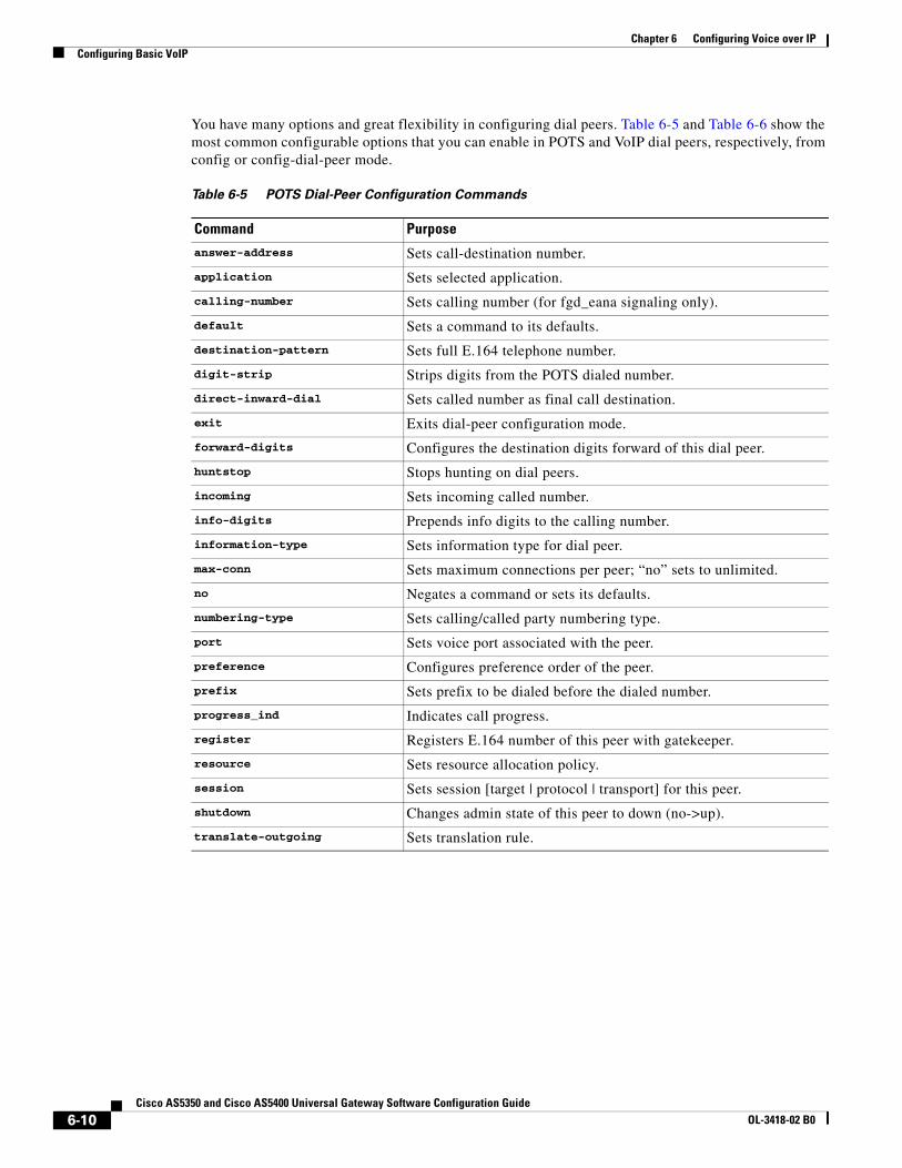
You have many options and great flexibility in configuring dial peers. Table 6-5 and Table 6-6 show the most common configurable options that you can enable in POTS and VoIP dial peers, respectively, from config or config-dial-peer mode.
Table 6-5 POTS Dial-Peer Configuration Commands
Command Purpose
answer-address Sets call-destination number.
application Sets selected application.
calling-number Sets calling number (for fgd_eana signaling only).
default Sets a command to its defaults.
destination-pattern Sets full E.164 telephone number.
digit-strip Strips digits from the POTS dialed number.
direct-inward-dial Sets called number as final call destination.
exit Exits dial-peer configuration mode.
forward-digits Configures the destination digits forward of this dial peer.
huntstop Stops hunting on dial peers.
incoming Sets incoming called number.
info-digits Prepends info digits to the calling number.
information-type Sets information type for dial peer.
max-conn Sets maximum connections per peer; “no” sets to unlimited.
no Negates a command or sets its defaults.
numbering-type Sets calling/called party numbering type.
port Sets voice port associated with the peer.
preference Configures preference order of the peer.
prefix Sets prefix to be dialed before the dialed number.
progress_ind Indicates call progress.
register Registers E.164 number of this peer with gatekeeper.
resource Sets resource allocation policy.
session Sets session [target | protocol | transport] for this peer.
shutdown Changes admin state of this peer to down (no->up).
translate-outgoing Sets translation rule.
6-10Cisco AS5350 and Cisco AS5400 Universal Gateway Software Configuration Guide
OL-3418-02 B0
Chapter 6 Configuring Voice over IPConfiguring Basic VoIP
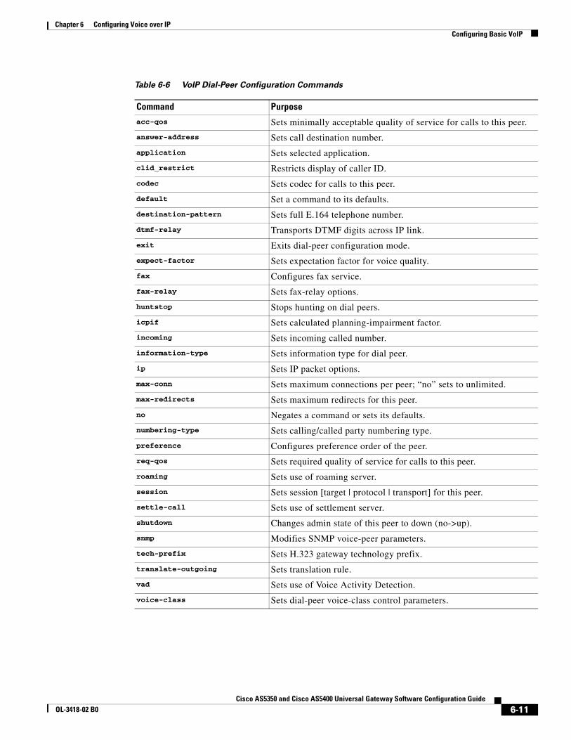
Table 6-6 VoIP Dial-Peer Configuration Commands
Command Purpose
acc-qos Sets minimally acceptable quality of service for calls to this peer.
answer-address Sets call destination number.
application Sets selected application.
clid_restrict Restricts display of caller ID.
codec Sets codec for calls to this peer.
default Set a command to its defaults.
destination-pattern Sets full E.164 telephone number.
dtmf-relay Transports DTMF digits across IP link.
exit Exits dial-peer configuration mode.
expect-factor Sets expectation factor for voice quality.
fax Configures fax service.
fax-relay Sets fax-relay options.
huntstop Stops hunting on dial peers.
icpif Sets calculated planning-impairment factor.
incoming Sets incoming called number.
information-type Sets information type for dial peer.
ip Sets IP packet options.
max-conn Sets maximum connections per peer; “no” sets to unlimited.
max-redirects Sets maximum redirects for this peer.
no Negates a command or sets its defaults.
numbering-type Sets calling/called party numbering type.
preference Configures preference order of the peer.
req-qos Sets required quality of service for calls to this peer.
roaming Sets use of roaming server.
session Sets session [target | protocol | transport] for this peer.
settle-call Sets use of settlement server.
shutdown Changes admin state of this peer to down (no->up).
snmp Modifies SNMP voice-peer parameters.
tech-prefix Sets H.323 gateway technology prefix.
translate-outgoing Sets translation rule.
vad Sets use of Voice Activity Detection.
voice-class Sets dial-peer voice-class control parameters.
6-11Cisco AS5350 and Cisco AS5400 Universal Gateway Software Configuration Guide
OL-3418-02 B0
Chapter 6 Configuring Voice over IPConfiguring Basic VoIP
Here are just a few of the things that you can do with these commands (which, as mentioned previously, you set from config or config-dial-peer mode):
• Configure destination patterns with wildcards and other operators.
Example: Use 6... to denote a 4-digit number beginning with 6.
• Define fixed-length or variable-length destination patterns.
Example: Use 6... to denote a 4-digit number beginning with 6; use 9t to denote a variable-length number beginning with 9.
• Specify that a prefix be added to calls on certain outgoing POTS call legs.
Example: Prepend 9 to calls that pass through a PBX requiring 9 to access an outside line; replace prefixes that are stripped by a dial peer because they match the destination pattern.
• Specify that certain dialed digits be expanded.
Example: Expand local 5-digit extensions beginning with 7 to the full E.164 number 1-408-7xxx.
• Create a hunt group to handle inbound calls.
Example: Establish multiple dial peers, each for a different voice port, and each containing the same destination pattern; the gateway directs inbound calls to the voice ports in sequence until it reaches one that is not busy.
• Set up preferences for routing outbound calls.
Example: Assign preference 1 to dial-peer voice 1, which directs outbound calls over the IP network; assign preference 2 to dial-peer voice 2, which directs calls over the PSTN; the gateway, looking for the longest exact match, finds both dial peers and then uses preference as a tie breaker among those matches.
Tip For more information, see Voice over IP for the Cisco AS5300, available online athttp://www.cisco.com/univercd/cc/td/doc/product/software/ios120/120newft/120t/120t3/voip5300/
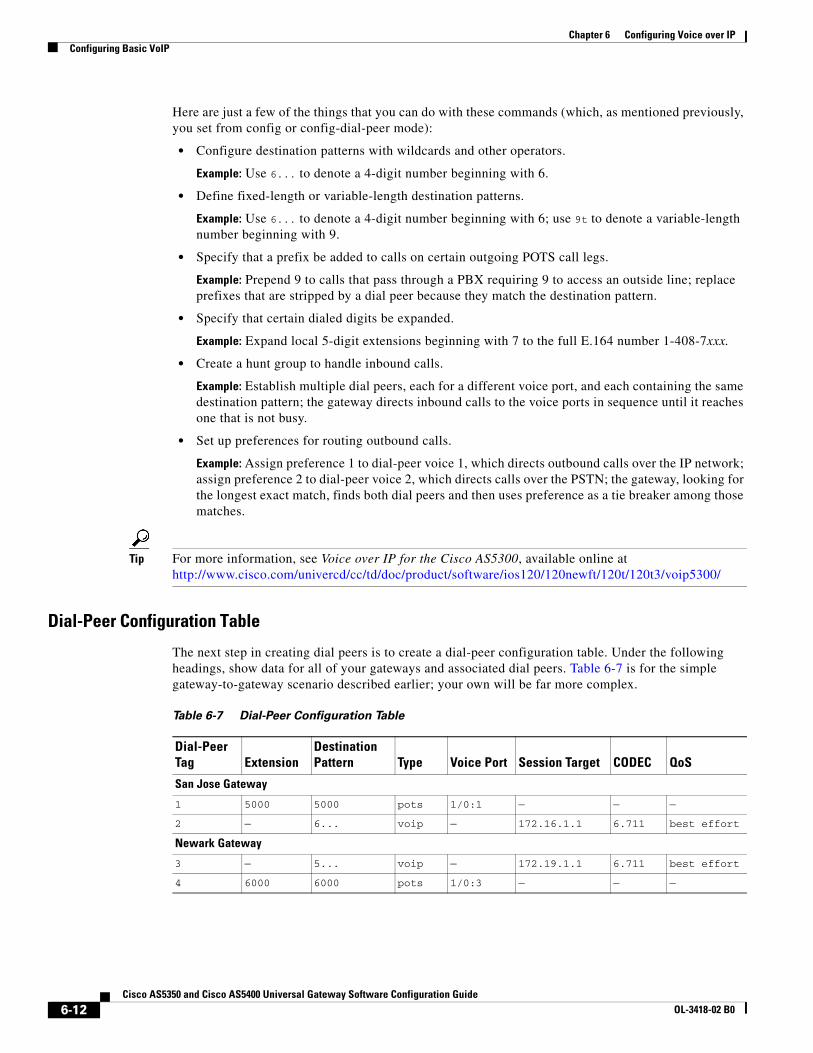
Dial-Peer Configuration Table
The next step in creating dial peers is to create a dial-peer configuration table. Under the following headings, show data for all of your gateways and associated dial peers. Table 6-7 is for the simple gateway-to-gateway scenario described earlier; your own will be far more complex.
Table 6-7 Dial-Peer Configuration Table
Dial-Peer Tag Extension
Destination Pattern Type Voice Port Session Target CODEC QoS
San Jose Gateway
1 5000 5000 pots 1/0:1 — — —
2 — 6... voip — 172.16.1.1 6.711 best effort
Newark Gateway
3 — 5... voip — 172.19.1.1 6.711 best effort
4 6000 6000 pots 1/0:3 — — —
6-12Cisco AS5350 and Cisco AS5400 Universal Gateway Software Configuration Guide
OL-3418-02 B0
Chapter 6 Configuring Voice over IPConfiguring Basic VoIP
Tip Consult the references at the end of the chapter before you create a dial-peer configuration table. See also Voice over IP for the Cisco AS5300, available online athttp://www.cisco.com/univercd/cc/td/doc/product/software/ios120/120newft/120t/120t3/voip5300/
Configuring Nextport Echo Canceller Control (optional)The AS5350, AS5400, and AS5400HPX Universal Gateways can detect 2100Hz tones, received in G.711 encoded VoIP packets. Customers can enable Nextport Voicecap to control the echo canceller when 2100Hz tones are received in G.711 encoded VoIP packets from either the PSTN or IP side of the network.
Note Nextport control over the echo canceller is only possible in G.711 codec modes.
Note It is not recommended that you enable Nextport control over the echo canceller in conjunction with modem-pass-through.
You enable IP tone detection and Nextport control over the echo canceller using CLI commands, but you must first set the following two Voicecap parameters to enable these features:
• v51 = 32769This setting enables IP side tone detection/notification and allows Nextport to disable the nonlinear processor (NLP) or the echo canceller upon reception of 2100Hz answer tones from the IP side. This setting is required in IOS Release 12.3T
• v2 = 512This setting enables the 250 millisecond silence detection. This setting is optional. When this setting is used in conjunction with the v51 = 32769 setting, Nextport restores the echo canceller to its original state after it detects the 250 millisecond silence.
The following example shows how to enable Nextport control over the echo canceller by creating a Voicecap entry and applying it to the voice-port.
1. Create Voicecap entries by entering the following CLI command:
Syntax:
router(config)#voicecap entry <name> <parameter list>
Example:
router(config)#voicecap entry npecho_ctrl v2=512 v51=32769
2. Apply the Voicecap entries to the voice port by entering the following CLI command:
Syntax:
router(config)#voicecap configure <name>
Example:
router(config)#voicecap configure npecho_ctrl
6-13Cisco AS5350 and Cisco AS5400 Universal Gateway Software Configuration Guide
OL-3418-02 B0
Chapter 6 Configuring Voice over IPConfiguring Basic VoIP
The following example shows the complete create and apply Voicecap procedure:
router(config)#voicecap entry npecho_ctrl v2=512 v51=32769router(config)#voice-port 3/0router(config-voiceport)#voicecap configure npecho_ctrlrouter(config-voiceport)#end
Note The Voicecap must be applied to the voice-port.
The IOS CLI show command does not display the current echo state. However, you can display the EST trace messages that show the tone detections and the resultant echo operations if you enable debug trace module f080 0010 x/y/z. Nextport enables and disables the nonlinear processor (NLP) and the echo canceller based on reception of 2100Hz answer tones from the IP side or PSTN side and generates EST trace messages for each tone detected and its echo operation. Nextport also detects the 250 milliseconds of silence and generates EST trace messages to indicate such detection and to indicate that the echo state has been restored.
To display the EST trace messages, enable debug trace module f080 0010 x/y/z as follows:
router# debug trace module f080 0010 s/d/m
s/d/m is defined as follows:
• s = slot
• d = dfc
• m = module number
When the default configuration values for Index 51 and Index 52 are used, IP tone detection and notification are disabled, and all existing features continue to function as normal.
The following example shows EST trace messages collected from the IOS console:
5350-torpedo#*Apr 26 21:40:51.735: 00:00:14: Port Trace Event:*Apr 26 21:40:51.735: Port : 3/00*Apr 26 21:40:51.735: Address : 0x3000000*Apr 26 21:40:51.735: Trace Event: 0x2*Apr 26 21:40:51.735: Data Format: ASCII*Apr 26 21:40:51.735: Data Len : 56*Apr 26 21:40:51.735: Data : Session 0x0144 Received Early ANS tone 0x01 from IP side*Apr 26 21:40:51.735: 00:00:14: Port Trace Event:*Apr 26 21:40:51.735: Port : 3/00*Apr 26 21:40:51.735:5350-torpedo# Address : 0x3000000*Apr 26 21:40:51.735: Trace Event: 0x2*Apr 26 21:40:51.735: Data Format: ASCII*Apr 26 21:40:51.735: Data Len : 63*Apr 26 21:40:51.735: Data : Session 0x0144 Received Tone Off ntf for code 0x01 from IP side*Apr 26 21:40:51.735: 00:00:14: Port Trace Event:*Apr 26 21:40:51.735: Port : 3/00*Apr 26 21:40:51.735: Address : 0x3000000*Apr 26 21:40:51.735: Trace Event: 0x2*Apr 26 21:40:51.735: Data Format: ASCII5350-torpedo#*Apr 26 21:40:51.735: Data Len : 45*Apr 26 21:40:51.735: Data : Session 0x0144 Received ANS tone 0x03 from IP*Apr 26 21:40:51.735: 00:00:14: Port Trace Event:*Apr 26 21:40:51.735: Port : 3/00*Apr 26 21:40:51.735: Address : 0x3000000*Apr 26 21:40:51.735: Trace Event: 0x2
6-14Cisco AS5350 and Cisco AS5400 Universal Gateway Software Configuration Guide
OL-3418-02 B0

Chapter 6 Configuring Voice over IPConfiguring Basic VoIP
*Apr 26 21:40:51.735: Data Format: ASCII*Apr 26 21:40:51.735: Data Len : 47*Apr 26 21:40:51.735: Data : Session 0x0144 Non-linear Processor Is Disabled*Apr5350-torpedo# 26 21:40:51.735: 00:00:14: Port Trace Event:*Apr 26 21:40:51.735: Port : 3/00*Apr 26 21:40:51.735: Address : 0x3000000*Apr 26 21:40:51.735: Trace Event: 0x2*Apr 26 21:40:51.735: Data Format: ASCII*Apr 26 21:40:51.735: Data Len : 63*Apr 26 21:40:51.735: Data : Session 0x0144 Received Tone Off ntf for code 0x03 from IP side*Apr 26 21:40:51.735: 00:00:14: Port Trace Event:*Apr 26 21:40:51.735: Port : 3/00*Apr 26 21:40:51.735:5350-torpedo# Address : 0x3000000*Apr 26 21:40:51.735: Trace Event: 0x2*Apr 26 21:40:51.735: Data Format: ASCII*Apr 26 21:40:51.735: Data Len : 47*Apr 26 21:40:51.735: Data : Session 0x0144 Received ANSam tone 0x07 from IP*Apr 26 21:40:51.735: 00:00:13: Port Trace Event:*Apr 26 21:40:51.735: Port : 3/00*Apr 26 21:40:51.735: Address : 0x3000000*Apr 26 21:40:51.735: Trace Event: 0x2*Apr 26 21:40:51.735: Data Format: ASCII*Apr 26 21:40:55350-torpedo#1.735: Data Len : 63*Apr 26 21:40:51.735: Data : Session 0x0144 Received Tone Off ntf for code 0x07 from IP side*Apr 26 21:40:51.739: 00:00:13: Port Trace Event:*Apr 26 21:40:51.739: Port : 3/00*Apr 26 21:40:51.739: Address : 0x3000000*Apr 26 21:40:51.739: Trace Event: 0x2*Apr 26 21:40:51.739: Data Format: ASCII*Apr 26 21:40:51.739: Data Len : 48*Apr 26 21:40:51.739: Data : Session 0x0144 Received /ANSam tone 0x0f from IP5350-torpedo#*Apr 26 21:40:51.739: 00:00:13: Port Trace Event:*Apr 26 21:40:51.739: Port : 3/00*Apr 26 21:40:51.739: Address : 0x3000000*Apr 26 21:40:51.739: Trace Event: 0x2*Apr 26 21:40:51.739: Data Format: ASCII*Apr 26 21:40:51.739: Data Len : 31*Apr 26 21:40:51.739: Data : Session 0x0144 ECAN Is Disabled*Apr 26 21:40:51.739: 00:00:04: Port Trace Event:*Apr 26 21:40:51.739: Port : 3/00*Apr 26 21:40:51.739: Address : 0x30000005350-torpedo#*Apr 26 21:40:51.739: Trace Event: 0x2*Apr 26 21:40:51.739: Data Format: ASCII*Apr 26 21:40:51.739: Data Len : 63*Apr 26 21:40:51.739: Data : Session 0x0144 Received Tone Off ntf for code 0x0f from IP side
*Apr 26 21:46:36.431: 00:00:08: Port Trace Event:*Apr 26 21:46:36.431: Port : 3/00*Apr 26 21:46:36.431: Address : 0x3000000 *Apr 26 21:46:36.431: Trace Event: 0x2*Apr 26 21:46:36.431: Data Format: ASCII*Apr 26 21:46:36.431: Data Len : 43*Apr 26 21:46:36.431: Data : Session 0x0144 detected 250 msec of silence*Apr 26 21:46:36.431: 00:00:08: Port Trace Event:*Apr 26 21:46:36.431: Port : 3/00*Apr 26 21:46:36.431: Address : 0x3000000 *Apr 26 21:46:36.435: Trace Event: 0x2*Apr 26 21:46:36.435: Data Format: ASCII
6-15Cisco AS5350 and Cisco AS5400 Universal Gateway Software Configuration Guide
OL-3418-02 B0
Chapter 6 Configuring Voice over IPVoice QoS Basics
*Apr 26 21:46:36.435: Data Len : 41*Apr 26 21:46:36.435: Data : Session 0x0144 Ecan State 0x0007 Restored
Voice QoS BasicsQuality of service refers to the ability of a network to provide differentiated service to selected network traffic over various underlying technologies. QoS is not inherent in a network infrastructure. Rather, you institute QoS by strategically enabling appropriate QoS features throughout an intranetwork or internetwork.
Voice traffic differs from data traffic in a number of ways:
• Data is often bursty by nature; voice is deterministic (smooth).
• Data applications resend dropped packets; voice applications can only conceal dropped packets.
• Data applications can usually tolerate some delay; voice applications must minimize delay, so that the recipient does not hear clips in the transmission.
All of these mandate use of QoS strategies to give strict priority to voice traffic, ensuring reliable delivery and minimal delay for networks that carry both voice and data.
Note The ITU-T G.114 recommendation specifies, for good voice quality, that no more than 150 ms of one-way, end-to-end delay should occur. In many situations, 200 ms may be acceptable.
QoS features for voice focus on two things—reliability and predictability. Reliability ensures delivery without packet loss. Predictability ensures delivery without excessive delay. Together, they serve to eliminate poor-quality voice transmission, including crackles and missing syllables that render a call unsatisfactory or even incoherent to the recipient.
Voice traffic requires real-time service, with steady and predictable throughput and low delay. In the presence of bursty, delay-tolerant data traffic, you must provide for voice traffic a differentiated—that is, higher-priority—level of service. Because networking equipment and devices that carry both data and voice cannot differentiate traffic that requires high-priority service from traffic that does not, your only means for ensuring that voice traffic is expedited or that it receives constant, predictable transmission across a backbone shared by data traffic is by enabling QoS features.
Effective end-to-end QoS throughout a network must serve disparate users, applications, organizations, and technologies, all at reasonable cost and effort. QoS features enable you to balance service levels for user satisfaction, granting priority service to voice while servicing data transmission to the degree of fairness that you require. In addition, other benefits can accrue: Internet service providers (ISPs), for example, can selectively enable QoS features so as to offer their customers differentiated services with different associated costs, as well as a spectrum of new applications and additional services based on these levels of service.
Cisco IOS software provides many features for optimizing QoS. Fine-tuning your network to adequately support VoIP almost certainly involves enabling some of these features. Be sure to read the sited references as you enable features, as the details of wide-scale QoS deployment are beyond the scope of this document. Also, keep in mind that you must configure QoS throughout your network, not just on the devices running VoIP, to optimize voice performance.
Not all QoS features are appropriate for all network devices and topologies. Edge devices and backbone devices do not necessarily perform the same operations. Briefly, edge devices handle packet classification, fragmentation, queuing, bandwidth management, and policing; backbone devices handle
6-16Cisco AS5350 and Cisco AS5400 Universal Gateway Software Configuration Guide
OL-3418-02 B0
Chapter 6 Configuring Voice over IPEnabling QoS Features for VoIP
switching and transport, congestion management, and queue management. Thus, the QoS tasks that they perform might differ. Consider the functions of both edge and backbone devices in your network, and enable QoS features for each type as appropriate.
Enabling QoS Features for VoIPThe following text briefly overviews some of the most important QoS features that you can enable, and cites references that you need to make informed decisions about the use and optimization of those features. Features discussed include the following:
• Congestion Management, page 6-17
– Weighted Fair Queuing
– Low-Latency Queuing
– IP RTP Priority and Frame Relay IP RTP Priority
– Resource Reservation
• Fragmentation and Interleaving, page 6-20
• Traffic Shaping for Frame Relay, page 6-20
• Other Bandwidth-Reduction Features, page 6-21
– Voice Encoding
– RTP Packet-Header Compression
– Serialization Delay
– Voice-Activity Detection
– Jitter Buffering
References in Additional Resources, page 6-24 provide more information.
Tip Should you have problems with QoS, try adding the following commands to your configuration:
• At the top-level configuration level:
io-cache enablevoice-fastpath enable
• Under the Fast Ethernet interface:
ip route-cache
Congestion Management
Weighted Fair Queuing
You need to avoid congestion on backbone gateways serving high-traffic, high-speed networks. A weighted-fair-queuing methodology called WRED (Weighted Random Early Detection) queues traffic according to priority values that you set (you set voice traffic to critical, for example), sets different
6-17Cisco AS5350 and Cisco AS5400 Universal Gateway Software Configuration Guide
OL-3418-02 B0
Chapter 6 Configuring Voice over IPEnabling QoS Features for VoIP
packet-drop thresholds for each queue, and drops packets in lower-priority queues as necessary so that higher-priority queues can be adequately served. This ensures that low-bandwidth conversations get through, even in the presence of other high-bandwidth applications.
Tip For more information and configuration options, see the following:
• Weighted Fair Queueing (WFQ), available online athttp://www.cisco.com/warp/public/732/Tech/quality.shtml
• Configuring Weighted Fair Queuing, available online athttp://www.cisco.com/univercd/cc/td/doc/product/software/ios120/12cgcr/qos_c/qcpart2/
Low-Latency Queuing
If you need to give voice packets priority but cannot allow them to starve other applications, the recommended queuing methodology is LLQ (Low-Latency Queuing), used in conjunction with IP RTP Priority. LLQ directs voice traffic into a priority queue, but allows you to place limits on the amount of traffic serviced at this and each other priority level before the next-lower priority level is serviced.
Tip For more information and configuration options, see Low-Latency Queuing, available online athttp://www.cisco.com/univercd/cc/td/doc/product/software/ios120/120newft/120t/120t7/
IP RTP Priority and Frame Relay IP RTP Priority
IP RTP Priority creates a strict-priority queue for VoIP calls. Only when the priority queue empties does the gateway process the other queues. The feature becomes active only when congestion exists on the interface.
Configure IP RTP Priority when you configure dial peers. Set an IP priority level to specify, in the packet header, that a voice call be accorded class-5 (critical) priority. Other queuing and traffic-management functions such as RSVP detect this information and provide priority service.
If your voice traffic passes through a Frame Relay network, the same argument holds, but the feature is called Frame Relay IP RTP Priority (described in the third reference below).
6-18Cisco AS5350 and Cisco AS5400 Universal Gateway Software Configuration Guide
OL-3418-02 B0
Chapter 6 Configuring Voice over IPEnabling QoS Features for VoIP
Tip For more information and configuration options, see the following:
• Voice over IP Quality of Service for Low-Speed PPP Links, available online athttp://www.cisco.com/warp/public/788/voice-qos/voip-mlppp.html
• IP RTP Priority, available online athttp://www.cisco.com/univercd/cc/td/doc/product/software/ios120/120newft/120t/120t5/iprtp.htm
• Frame Relay IP RTP Priority, available online athttp://www.cisco.com/univercd/cc/td/doc/product/software/ios120/120newft/120t/120t7/friprtp.htm
Resource Reservation
You can set things up so that your and any other similarly-set-up sending or receiving system can reserve bandwidth, on a call-by-call basis, along a router path by enabling RSVP (Resource Reservation Protocol) on all WAN links that transport voice traffic.
Configure RSVP when you configure dial peers. Do not enable RSVP in conjunction with Frame Relay traffic shaping.
Tip For more information and configuration options, see Voice over IP for the Cisco AS5300, available online athttp://www.cisco.com/univercd/cc/td/doc/product/software/ios120/120newft/120t/120t3/voip5300/
Call-Admission Control
You can gracefully prevent calls from entering your Cisco AS5850 from the PSTN when certain resources—such as CPU, memory, and interfaces—are not available to process those calls. Such intervention is called call-admission control.
If your system experiences high CPU usage, large call volumes, or occasional large numbers of simultaneous calls, you need to control two specific aspects of call-admission control: call spikes and call thresholds. Doing so is especially important if you handle transactions involving debit cards, which require AAA and similar types of support.
Configure call spikes to limit the number of incoming calls over a short period of time. Configure call thresholds to define under which circumstances system resources should be enabled.
Tips For more information and configuration options, including how to configure limits on call spikes and call thresholds, refer to the following document:
• Call Admission Control for H.323 VoIP Gateways, available online athttp://www.cisco.com/univercd/cc/td/doc/product/software/ios122/122newft/122limit/122x/122xa/122xa_2/ft_pfavb.htm
6-19Cisco AS5350 and Cisco AS5400 Universal Gateway Software Configuration Guide
OL-3418-02 B0
Chapter 6 Configuring Voice over IPEnabling QoS Features for VoIP
Fragmentation and InterleavingTransmission of voice packets, usually small (60 to 240 bytes) in size, can be unduly delayed in networks that also transmit large data packets. Fragmenting large data packets into smaller ones and interleaving voice packets among the fragments reduces jitter and delay. Use fragmentation and interleaving in conjunction with a congestion-management technique such as IP RTP Priority and/or RSVP if you have a low-bandwidth (<1.5 Mbps) WAN circuit, but not if you have a high-bandwidth (>1.5 Mbps) WAN circuit. The recommended fragmentation and interleaving methodology is FRF.12 for Voice over Frame Relay, Multilink PPP for VoIP-over-PPP leased lines.
Tip For more information and configuration options, see the following:
• For FRF.12, Frame Relay Fragmentation for Voice, available online athttp://www.cisco.com/warp/public/788/vofr/fr_frag.html
• For Multilink PPP, Voice over IP Quality of Service for Low-Speed PPP Links, available online athttp://www.cisco.com/warp/public/788/voice-qos/voip-mlppp.html
Traffic Shaping for Frame RelayYou must regulate traffic flow so that packets arrive at their destination only as fast as the destination can handle them. You do so by buffering packets that are generated faster than a configured value, and releasing them at that value. It is especially important that you enable traffic shaping in Frame Relay networks, but not in conjunction with RSVP. Do not enable traffic shaping with PPP leased lines.
Tip For more information and configuration options, see the following:
• VoIP over Frame Relay with Quality of Service (Fragmentation, Traffic Shaping, IP RTP Priority, available online athttp://www.cisco.com/warp/public/788/voice-qos/voip-ov-fr-qos.html
• Frame Relay Traffic Shaping for Voice, available online athttp://www-vdtl/SPUniv/Vofr/FR_traffic.htm
Note Successful traffic shaping on a Frame Relay network requires that you set not just this but many other QoS features. Refer to these references and the “Additional Resources” section for more information.
6-20Cisco AS5350 and Cisco AS5400 Universal Gateway Software Configuration Guide
OL-3418-02 B0
Chapter 6 Configuring Voice over IPEnabling QoS Features for VoIP
Other Bandwidth-Reduction Features
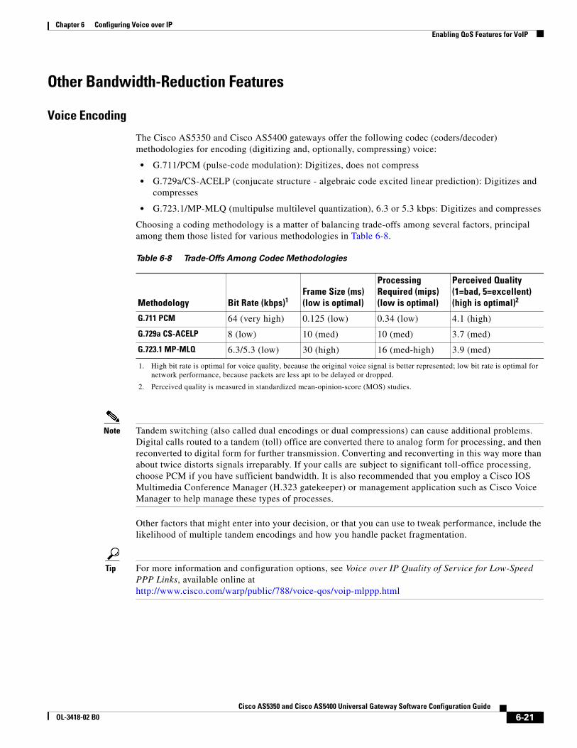
Voice Encoding
The Cisco AS5350 and Cisco AS5400 gateways offer the following codec (coders/decoder) methodologies for encoding (digitizing and, optionally, compressing) voice:
• G.711/PCM (pulse-code modulation): Digitizes, does not compress
• G.729a/CS-ACELP (conjucate structure - algebraic code excited linear prediction): Digitizes and compresses
• G.723.1/MP-MLQ (multipulse multilevel quantization), 6.3 or 5.3 kbps: Digitizes and compresses
Choosing a coding methodology is a matter of balancing trade-offs among several factors, principal among them those listed for various methodologies in Table 6-8.
Note Tandem switching (also called dual encodings or dual compressions) can cause additional problems. Digital calls routed to a tandem (toll) office are converted there to analog form for processing, and then reconverted to digital form for further transmission. Converting and reconverting in this way more than about twice distorts signals irreparably. If your calls are subject to significant toll-office processing, choose PCM if you have sufficient bandwidth. It is also recommended that you employ a Cisco IOS Multimedia Conference Manager (H.323 gatekeeper) or management application such as Cisco Voice Manager to help manage these types of processes.
Other factors that might enter into your decision, or that you can use to tweak performance, include the likelihood of multiple tandem encodings and how you handle packet fragmentation.
Tip For more information and configuration options, see Voice over IP Quality of Service for Low-Speed PPP Links, available online athttp://www.cisco.com/warp/public/788/voice-qos/voip-mlppp.html
Table 6-8 Trade-Offs Among Codec Methodologies
Methodology Bit Rate (kbps)1
1. High bit rate is optimal for voice quality, because the original voice signal is better represented; low bit rate is optimal for network performance, because packets are less apt to be delayed or dropped.
Frame Size (ms)(low is optimal)
Processing Required (mips)(low is optimal)
Perceived Quality (1=bad, 5=excellent)(high is optimal)2
2. Perceived quality is measured in standardized mean-opinion-score (MOS) studies.
G.711 PCM 64 (very high) 0.125 (low) 0.34 (low) 4.1 (high)
G.729a CS-ACELP 8 (low) 10 (med) 10 (med) 3.7 (med)
G.723.1 MP-MLQ 6.3/5.3 (low) 30 (high) 16 (med-high) 3.9 (med)
6-21Cisco AS5350 and Cisco AS5400 Universal Gateway Software Configuration Guide
OL-3418-02 B0
Chapter 6 Configuring Voice over IPEnabling QoS Features for VoIP
RTP Packet-Header Compression
Because of the repetitive nature of subsequent IP/UDP/RTP (network/transport/session-layer) headers, you can compress them significantly. A recommended methodology is cRTP (Compressed Real-Time Transfer Protocol), which, by tracking first-order and second-order differences between headers on subsequent packets, compresses the 40-byte header to just 2 or 4 (without or with UDP checksum) bytes. Other methodologies may be preferable if cRTP’s high CPU usage causes delay. Employ a compression methodology on both ends of low-bandwidth (<1.5 Mbps) WAN circuits, but not at all on high-speed (>1.5 Mbps) WANs.
Tip For more information and configuration options, see Voice over IP Quality of Service for Low-Speed PPP Links, available online athttp://www.cisco.com/warp/public/788/voice-qos/voip-mlppp.html
Serialization Delay
You can control packet (payload) size—which, in turn, controls how long one packet takes to be placed on the system interface. Set this in bytes, ideally equating to no greater than 20 ms (typically equivalent to two 10-ms voice samples per packet). Increasing serialization delay increases end-to-end delay. You want to incur no more than 150-to-200 ms of 1-way, end-to-end delay.
Note Take care when you assign a payload size for your chosen codec. To assign a codec and payload size, you use the codec codec bytes payload_size command under the dial-peer voip command. Although the codec command permits a wide range of payload sizes, the universal port card permits a much smaller range of sizes, to help ensure that end-to-end delay for voice signals does not exceed 200 ms. For the (default) g729r8 codec, these sizes are just 10ms, 20ms (recommended), and 30ms, which correspond to 10 bytes, 20 bytes, and 30 bytes of payload. If your network uses a variety of gateway and router types, you may need to ensure that payload sizes are set both optimally (so as not to incur excessive end-to-end delay) and consistently.
Tip For more information and configuration options, see Voice over IP—Per Call Bandwidth Consumption, available online athttp://www.cisco.com/warp/public/788/pkt-voice-general/bwidth_consume.html
6-22Cisco AS5350 and Cisco AS5400 Universal Gateway Software Configuration Guide
OL-3418-02 B0
Chapter 6 Configuring Voice over IPEnabling QoS Features for VoIP
Voice-Activity Detection
Because telephone users generally speak in turn, a typical voice conversation contains up to 50 percent silence. A feature called VAD (Voice Activity Detection) causes the gateway to transmit when speech starts and cease transmitting when speech stops. During silences, it generates white noise so that callers do not mistake silence for a disconnected call. By suppressing packets of silence, VAD enables you to handle more calls. For VoIP bandwidth planning, assume that VAD reduces bandwidth by 35 percent. Enable VAD if you wish to allocate more bandwidth to other types of traffic.
A possible problem with VAD is that it tends to clip the start and end of speech. To avoid activation during very short pauses and to compensate for clipping, VAD waits approximately 200 ms after speech stops before stopping transmission. Upon restarting transmission, it includes the previous 5 ms of speech along with the current speech.
VAD disables itself on a call automatically if ambient noise prevents it from distinguishing between speech and background noise.
Tip For more information and configuration options, see Voice over IP Quality of Service for Low-Speed PPP Links, available online athttp://www.cisco.com/warp/public/788/voice-qos/voip-mlppp.html
Jitter Buffering
Jitter occurs when there is a variation between when a voice packet is expected to arrive and when it actually arrives, causing discontinuity in the voice stream. Cisco devices handle jitter by buffering received data and playing it back smoothly.
Default jitter-buffer settings are sufficient in most networks under normal situations. If you experience choppy voice signals or poor voice quality, increase the size of the buffer. If you experience significant overall network delay, decrease the size. If your network is noisy and you use jitter-prone applications such as unified messaging server or interactive voice response, select fixed mode and a relatively high nominal value. Note that the trade-off for increasing jitter-buffer size is a corresponding increase in delay.
Cisco’s jitter buffers are normally sized dynamically, and adaptive mode plus default buffer size should suffice. But adjust mode and size as needed.
6-23Cisco AS5350 and Cisco AS5400 Universal Gateway Software Configuration Guide
OL-3418-02 B0
Chapter 6 Configuring Voice over IPAdditional Resources
Additional ResourcesIn configuring VoIP and setting QoS parameters for your network, you will have to wrestle with a large number of decisions and parameters. This chapter provides a brief overview on this very complex subject. The following sources provide more information:
• Cisco documents on IP telephony solutions:http://www.cisco.com/univercd/cc/td/doc/product/voice/ip_tele/index.htm
• Cisco feature modules: http://www.cisco.com/univercd/cc/td/doc/product/software/,under listings for your Cisco IOS release
• Cisco IOS documents:
– Cisco IOS Quality of Service Solutions Configuration Guide
– Cisco IOS Multiservice Applications Command Reference
– Cisco IOS Voice, Video, and Fax Configuration Guide
– Cisco IOS Voice, Video, and Fax Command Reference
Note Start your search at http://www.cisco.com/univercd/cc/td/doc/product/software/and then go to your Cisco IOS release.
• Commercially available books:
– Voice Over IP Fundamentals, Jonathan Davidson & James Peters, Cisco Press, 2000
– Cisco Packetized Voice & Data Integration, Robert Caputo, McGraw-Hill, 2000
• VoIP references for Cisco devices:
– Cisco IP Telephony Network Design Guide, available online athttp://www.cisco.com/univercd/cc/td/doc/product/voice/ip_tele/network/index.htm
– Cisco AVVID QoS Design Guide, available online athttp://www.cisco.com/univercd/cc/td/doc/product/voice/ip_tele/avvidqos/index.htm
– Voice-over-IP Quick Start Guide, available online athttp://www.cisco.com/univercd/cc/td/doc/product/access/acs_mod/1750/voipqsg/voipqsg.htm
– Configuring H.323 VoIP Gateway for Cisco Access Platforms, available online athttp://www.cisco.com/univercd/cc/td/doc/product/access/acs_serv/5300/cfios/cfselfea/0044gw.htm
– Monitoring Voice and Fax Services on the Cisco AS5400 Universal Gateway, available online athttp://www.cisco.com/univercd/cc/td/doc/product/software/;select your Cisco IOS release and search for this title
– Voice over IP for the Cisco AS5300, available online athttp://www.cisco.com/univercd/cc/td/doc/product/software/ios120/120newft/120t/120t3/voip5300/voip53_1.htm
– Voice over IP for the Cisco AS5800, available online athttp://www.cisco.com/univercd/cc/td/doc/product/access/nubuvoip/voip5800/
– (Cisco 2600 Series) Software Configuration Guide, available online athttp://www.cisco.com/univercd/cc/td/doc/product/access/acs_mod/cis2600/software/voice.htm
6-24Cisco AS5350 and Cisco AS5400 Universal Gateway Software Configuration Guide
OL-3418-02 B0
Chapter 6 Configuring Voice over IPAdditional Resources
– Configuring Voice over IP for the Cisco 3600 Series, available online athttp://www.cisco.com/univercd/cc/td/doc/product/software/ios120/12cgcr/voice_c/vcprt1/vcvoip.htm
– Voice over IP for the Cisco 2600/3600 Series, available online athttp://www.cisco.com/univercd/cc/td/doc/product/access/nubuvoip/voip3600/index.htm
• Other websites:
– Voice over IP Technology Tutorial and First Approach:http://www.comsoc.org.mx/standard/voip.thm
– Voice over Packet Tutorial: http://www.webproforum.com/voice_packet/index.html
– Tutorials on various telecommunications topics: http://www.iec.org/tutorials/
– VoIP references: http://www.netlab.ohio-state.edu/~jain/refs/ref_voip.htm
6-25Cisco AS5350 and Cisco AS5400 Universal Gateway Software Configuration Guide
OL-3418-02 B0

Chapter 6 Configuring Voice over IPAdditional Resources
6-26Cisco AS5350 and Cisco AS5400 Universal Gateway Software Configuration Guide
OL-3418-02 B0