Configuring VMware vSphere 6 with Oracle Flash Storage Systems · CONFIGURING VMWARE VSPHERE 6 WITH...
52
Configuring VMware vSphere 6 with Oracle Flash Storage Systems ORACLE WHITE PAPER | APRIL 2016
Transcript of Configuring VMware vSphere 6 with Oracle Flash Storage Systems · CONFIGURING VMWARE VSPHERE 6 WITH...
Configuring VMware vSphere 6 with Oracle Flash Storage Systems O R A C L E W H I T E P A P E R | A P R I L 2 0 1 6
CONFIGURING VMWARE VSPHERE 6 WITH ORACLE FLASH STORAGE SYSTEMS
Disclaimer
The following is intended to outline our general product direction. It is intended for information
purposes only, and may not be incorporated into any contract. It is not a commitment to deliver any
material, code, or functionality, and should not be relied upon in making purchasing decisions. The
development, release, and timing of any features or functionality described for Oracle’s products
remains at the sole discretion of Oracle.
Table of Contents
Disclaimer 4
Introduction 6
Executive Summary 6
Intended Audience 7
Virtualization Plug-In Integration Overview 7
VMware vSphere Environment 7
VMware vSphere Product Overview 7
Oracle LUNs in a VMware Environment 8
Summary of Best Practices 9
Design and Configuration 14
Discover the Oracle FS System 14
Configure the FC HBA BIOS Settings 15
Queue Depth and Timeouts 16
HBA Queue Depth 17
Set the Driver Queue Depth on FC HBAs 17
Set the Queue Depth for the iSCSI Initiator 18
Storage Driver Queue Depth 18
ESXi Host Queue Depth 18
FC Front End Ports Queue Depth 18
2-Gigabit Front End Ports 18
4 Gigabit, 8 Gigabit, and 16 Gigabit Front End Ports 19
iSCSI Queue Depth 20
2 CONFIGURING VMWARE VSPHERE 6 WITH ORACLE FLASH STORAGE SYSTEMS
ESXi Host Queue Depth 20
Set the Queue Depth Using the Esxtop Utility 20
Modifying the VMFS Queue Depth 21
Globally Set the DSNRO 21
Adaptive Queue Depth Settings 22
Guest Operating System Queue Depth Settings 22
LSI Logic Parallel (LSI_SCSI) 23
LSI Logic SAS (LSI_SAS) 23
VMware Paravirtual SCSI 23
Best Practice on Setting Timeouts 24
Set Disk Timeouts on Operating Systems 24
Set Disk Timeouts for a Windows VM 24
Set Disk Timeouts for a Linux VM 25
Configure the iSCSI Initiator 25
Configure the iSCSI Initiator 26
Virtual Switch Recommendations 26
Multi-VLAN Recommendations 26
Adjust the Claim Rules on the ESXi Host 27
Unmap Volumes from an ESXi Host 27
Extend VMware Volumes 27
Increase VMFS Datastore Capacity 28
Increasing the Size of a VMDK File 28
VMware and Oracle Storage Options 29
3 CONFIGURING VMWARE VSPHERE 6 WITH ORACLE FLASH STORAGE SYSTEMS
FC Switch Zoning 29
Single Initiator Zoning 29
WWN Zoning 29
Port Zoning 29
Virtual Ports 29
Boot ESXi Hosts from SAN 30
Volume Sizing 30
Virtual Machines per Datastore 30
LUN Mapping Layout 31
Multiple Virtual Machines per LUN 31
Page Files on Separate Datastores 32
Separation of Virtual Machine Swap Files 32
VMFS Partition Alignment 32
Adding a New VMFS Extent to an Existing Datastore 33
Virtual Machine Placement 33
Raw Device Mapping 34
Advantages of Using RDMs 34
Disadvantages of Using RDMs 34
Increase the Size of an RDM 35
Replication of VSS-Aware Applications 35
Provisioning and Virtual Disks 35
Guest Virtual SCSI Adapter Selection 36
Mapping Volumes to an ESXi Server 37
4 CONFIGURING VMWARE VSPHERE 6 WITH ORACLE FLASH STORAGE SYSTEMS
Basic Volume Mapping 37
Basic Volume Mappings on the Oracle FS System 37
Multipathed Volumes 38
VMware Multipathing Policies 38
Round Robin Policy 39
Fixed Policy 39
Most Recently Used Policy 39
Conditions for Path Selection Policy Changes 39
Set Round Robin as the Default Policy 41
Switch an Entire Cluster from Fixed to Round Robin 41
Multipathing Using a Fixed Policy 41
Multipathing Using the Round Robin Policy 42
Change the Path Selection Policy 43
Asymmetric Logical Unit Access 43
VMware Upgrades 43
Upgrade Considerations 44
vSphere ESXi Host Upgrade Considerations 44
ESXi Host Upgrade Methods 45
Upgrading Clusters 45
Upgrading ESXi Hosts 45
Upgrading Virtual Machines 46
Upgrading VMFS 46
Upgrading a VMFS Datastore 47
Recommendation for a VMFS Datastore Upgrade 48
5 CONFIGURING VMWARE VSPHERE 6 WITH ORACLE FLASH STORAGE SYSTEMS
Conclusion 48
Related Documentation 48
Oracle Flash Storage Documentation 48
Oracle Technical Support and Resources 48
VMware vSphere 6.x Documentation 49
ESXi Host Configuration Documentation 49
VMware Upgrade Documentation 49
Additional VMware Resource 49
6 CONFIGURING VMWARE VSPHERE 6 WITH ORACLE FLASH STORAGE SYSTEMS
Introduction A finely-tuned VMware host environment connected to an Oracle Flash Storage (FS) System can provide optimal performance. Conversely, a misconfigured VMware host can suffer from LUN thrashing, non-optimized path access, and poor overall performance. This white paper outlines best practices on how to set up Oracle FS System storage with VMware vSphere 6. The best practices are designed to prevent host misconfiguration and to optimize system performance using the following methods:
» Configuration examples, tips, recommended settings, and other storage guidelines for integrating VMware ESXi 6.x hosts with the Oracle FS System
» Information about how VMware interacts with various Oracle FS System features » Configuration procedures for setting up the VMware vSphere ESXI 6.x host to run seamlessly using the Oracle
FS System » Information about upgrading from ESXI 5.5 to ESXI 6.0 when connected to the Oracle FS System.
Executive Summary
Oracle FS System technology enables companies to extend their virtual infrastructures to include the benefits of advanced storage virtualization. When supported with the correct underlying storage platform, vCenter server virtualization delivers greater consolidation, administrative efficiency, business continuity, and cost savings.
This white paper reviews the configuration and best practices for implementing VMware vSphere with unique Oracle FS features, such as the following:
» vSphere integration » LUN auto-tiering » Multipathing » Thin provisioning » Dynamic and adaptive optimization » Priority optimization » Oracle FS cloning » Volume copy
Implementing the Oracle FS System with VMware vSphere 6 provides the following benefits:
» Increase consolidation savings by substantially increasing virtual machine density » Simplify storage provisioning and management time by orders of magnitude » Maximize savings through lower storage costs » Using the Oracle FS System data protection features, secure the data center and achieve the recovery point
objective (RPO) and recovery time objective (RTO) » Deliver performance to virtualized VMware environments
7 CONFIGURING VMWARE VSPHERE 6 WITH ORACLE FLASH STORAGE SYSTEMS
Intended Audience The information is designed for professionals who architect, design, manage, and support the Oracle FS System in a VMware vSphere 6.x environment.
At a minimum, administrators who need to leverage Oracle FS storage within a VMware environment should be familiar with the following concepts:
» Concepts related to the VMware ESXi Server, vCenter, and Oracle FS System » Installation and configuration of VMware vSphere 6.x » Configuration and operation of the Oracle FS System » Operating systems, such as Microsoft Windows, Solaris, and Linux
Virtualization Plug-In Integration Overview The Oracle vSphere Plug-In for Oracle FS Systems integrates access to your Oracle FS System with VMware vSphere and the VMware vCenter Server. You can view, provision, and manage your Oracle FS System in the vSphere Client.
VMware vSphere Environment
The VMware vSphere environment makes it possible to manage disparate physical infrastructure in a datacenter as virtual pools of resources. Resources include processors, memory, storage, and networking components. There are many VMware applications that you can add to the vSphere environment to provide virtual machine and disk migration, load balancing, fault tolerance, high availability, backups, and distributed networking. The ESXi hosts use their network connections to access storage and to enable remote management.
VMware vSphere Product Overview
The VMware vSphere environment is composed of the vSphere, vCenter Server, and ESXi Host products. The Oracle vSphere Plug-In for Oracle FS Systems give you access to the following functionality through the vSphere Web Client:
» View underlying data storage for hosts, virtual machines, and datastores. » Create datastores on existing or new Oracle FS System LUNs. » View, create, modify, and delete LUNs. » View SAN hosts, Host Groups, Volume Groups, and Storage Domains. » Create snapshots of datastores on Oracle FS System storage, and recover data from snapshots.
8 CONFIGURING VMWARE VSPHERE 6 WITH ORACLE FLASH STORAGE SYSTEMS
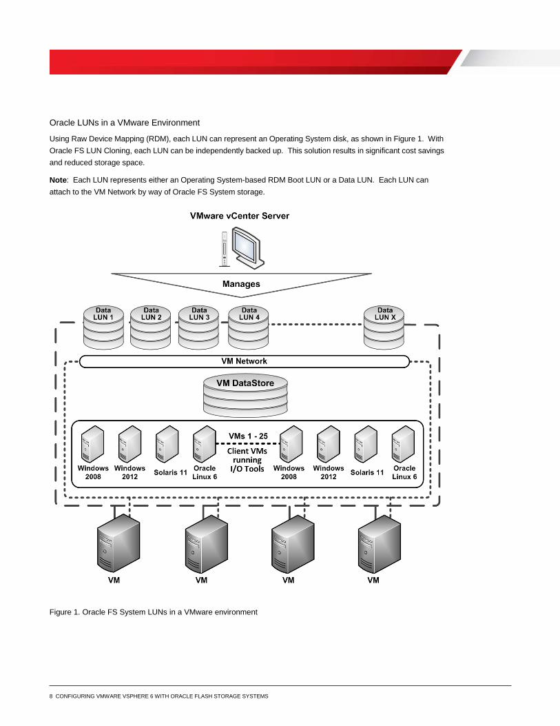
Oracle LUNs in a VMware Environment
Using Raw Device Mapping (RDM), each LUN can represent an Operating System disk, as shown in Figure 1. With Oracle FS LUN Cloning, each LUN can be independently backed up. This solution results in significant cost savings and reduced storage space.
Note: Each LUN represents either an Operating System-based RDM Boot LUN or a Data LUN. Each LUN can attach to the VM Network by way of Oracle FS System storage.
Figure 1. Oracle FS System LUNs in a VMware environment
9 CONFIGURING VMWARE VSPHERE 6 WITH ORACLE FLASH STORAGE SYSTEMS
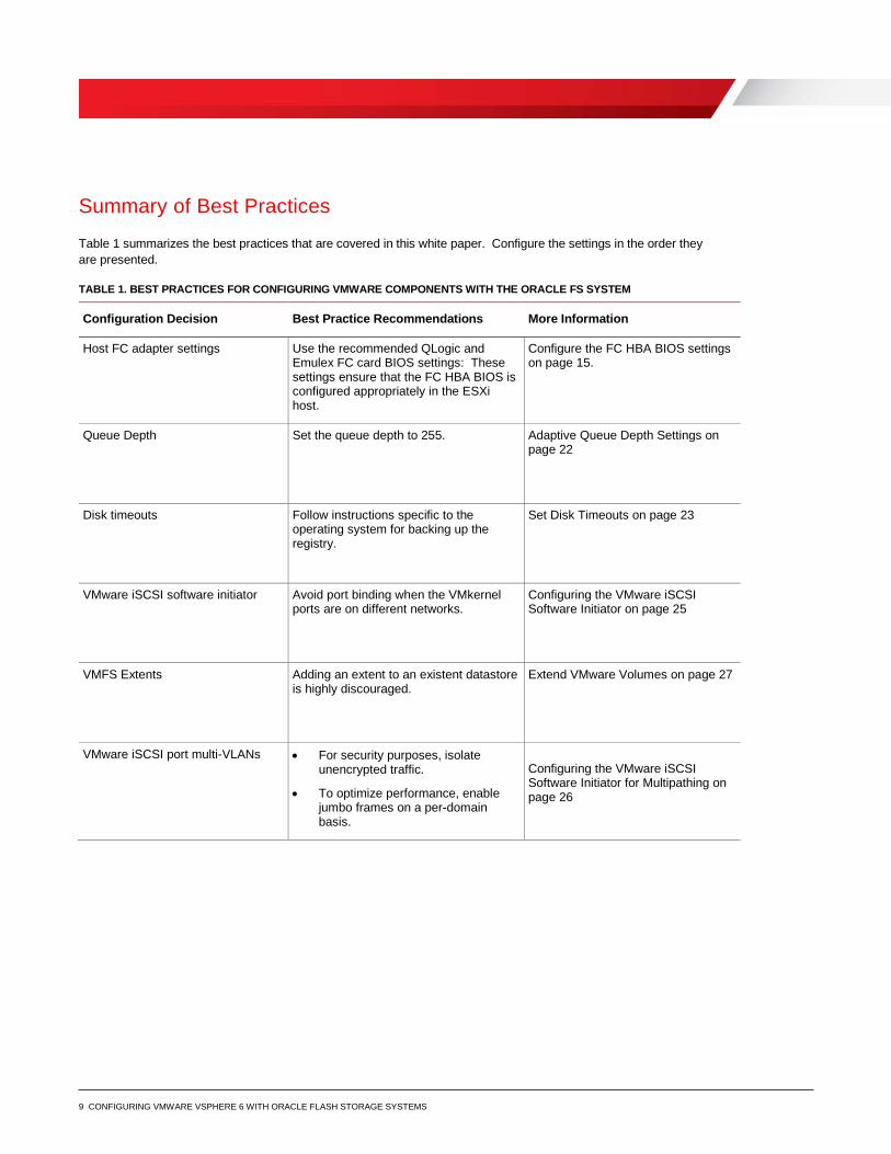
Summary of Best Practices
Table 1 summarizes the best practices that are covered in this white paper. Configure the settings in the order they are presented.
TABLE 1. BEST PRACTICES FOR CONFIGURING VMWARE COMPONENTS WITH THE ORACLE FS SYSTEM
Configuration Decision Best Practice Recommendations More Information
Host FC adapter settings Use the recommended QLogic and Emulex FC card BIOS settings: These settings ensure that the FC HBA BIOS is configured appropriately in the ESXi host.
Configure the FC HBA BIOS settings on page 15.
Queue Depth Set the queue depth to 255. Adaptive Queue Depth Settings on page 22
Disk timeouts Follow instructions specific to the operating system for backing up the registry.
Set Disk Timeouts on page 23
VMware iSCSI software initiator Avoid port binding when the VMkernel ports are on different networks.
Configuring the VMware iSCSI Software Initiator on page 25
VMFS Extents Adding an extent to an existent datastore is highly discouraged.
Extend VMware Volumes on page 27
VMware iSCSI port multi-VLANs • For security purposes, isolate unencrypted traffic.
• To optimize performance, enable jumbo frames on a per-domain basis.
Configuring the VMware iSCSI Software Initiator for Multipathing on page 26
10 CONFIGURING VMWARE VSPHERE 6 WITH ORACLE FLASH STORAGE SYSTEMS
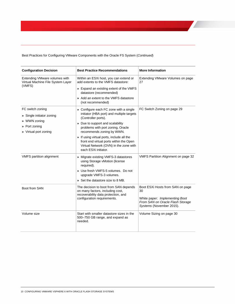
Best Practices for Configuring VMware Components with the Oracle FS System (Continued)
Configuration Decision Best Practice Recommendations More Information
Extending VMware volumes with Virtual Machine File System Layer (VMFS)
Within an ESXi host, you can extend or add extents to the VMFS datastore:
» Expand an existing extent of the VMFS datastore (recommended)
» Add an extent to the VMFS datastore (not recommended)
Extending VMware Volumes on page 27
FC switch zoning
» Single initiator zoning » WWN zoning » Port zoning » Virtual port zoning
» Configure each FC zone with a single initiator (HBA port) and multiple targets (Controller ports).
» Due to support and scalability problems with port zoning, Oracle recommends zoning by WWN.
» If using virtual ports, include all the front end virtual ports within the Open Virtual Network (OVN) in the zone with each ESXi initiator.
FC Switch Zoning on page 29
VMFS partition alignment » Migrate existing VMFS-3 datastores using Storage vMotion (license required).
» Use fresh VMFS-5 volumes. Do not upgrade VMFS-3 volumes.
» Set the datastore size to 8 MB.
VMFS Partition Alignment on page 32
Boot from SAN The decision to boot from SAN depends on many factors, including cost, recoverability data protection, and configuration requirements.
Boot ESXi Hosts from SAN on page 30 White paper: Implementing Boot From SAN on Oracle Flash Storage Systems (November 2015).
Volume size Start with smaller datastore sizes in the 500–750 GB range, and expand as needed.
Volume Sizing on page 30
11 CONFIGURING VMWARE VSPHERE 6 WITH ORACLE FLASH STORAGE SYSTEMS
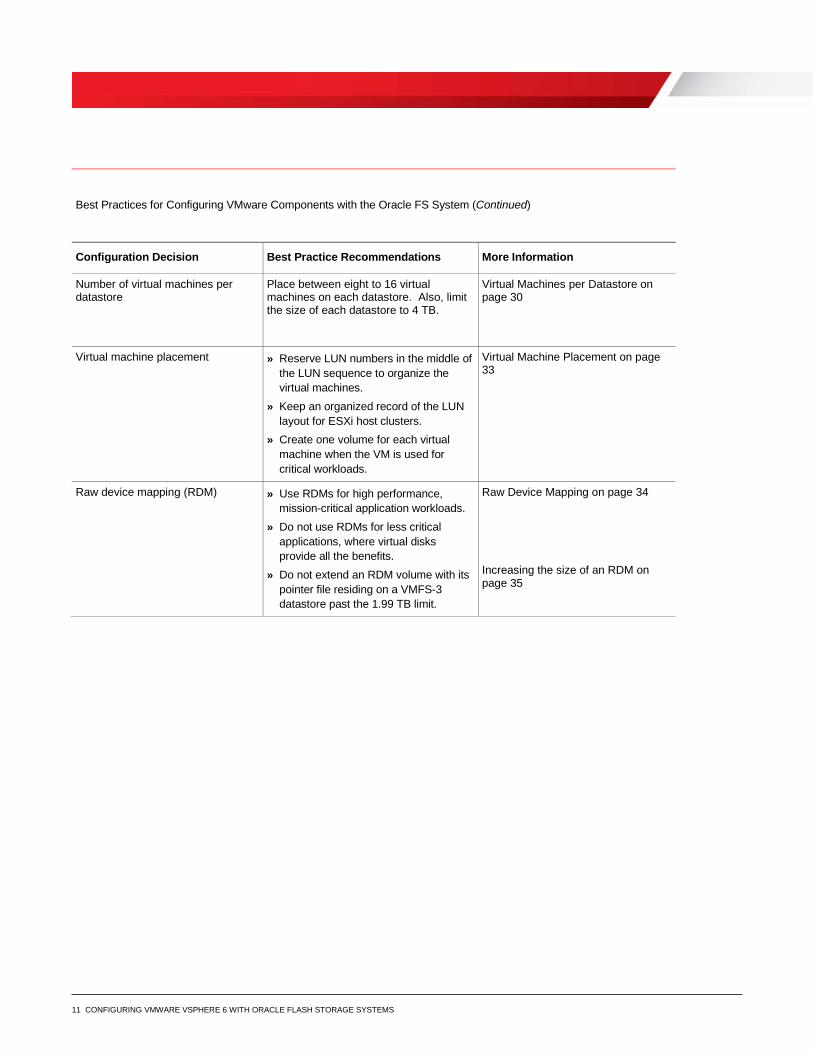
Best Practices for Configuring VMware Components with the Oracle FS System (Continued)
Configuration Decision Best Practice Recommendations More Information
Number of virtual machines per datastore
Place between eight to 16 virtual machines on each datastore. Also, limit the size of each datastore to 4 TB.
Virtual Machines per Datastore on page 30
Virtual machine placement » Reserve LUN numbers in the middle of the LUN sequence to organize the virtual machines.
» Keep an organized record of the LUN layout for ESXi host clusters.
» Create one volume for each virtual machine when the VM is used for critical workloads.
Virtual Machine Placement on page 33
Raw device mapping (RDM) » Use RDMs for high performance, mission-critical application workloads.
» Do not use RDMs for less critical applications, where virtual disks provide all the benefits.
» Do not extend an RDM volume with its pointer file residing on a VMFS-3 datastore past the 1.99 TB limit.
Raw Device Mapping on page 34 Increasing the size of an RDM on page 35
12 CONFIGURING VMWARE VSPHERE 6 WITH ORACLE FLASH STORAGE SYSTEMS
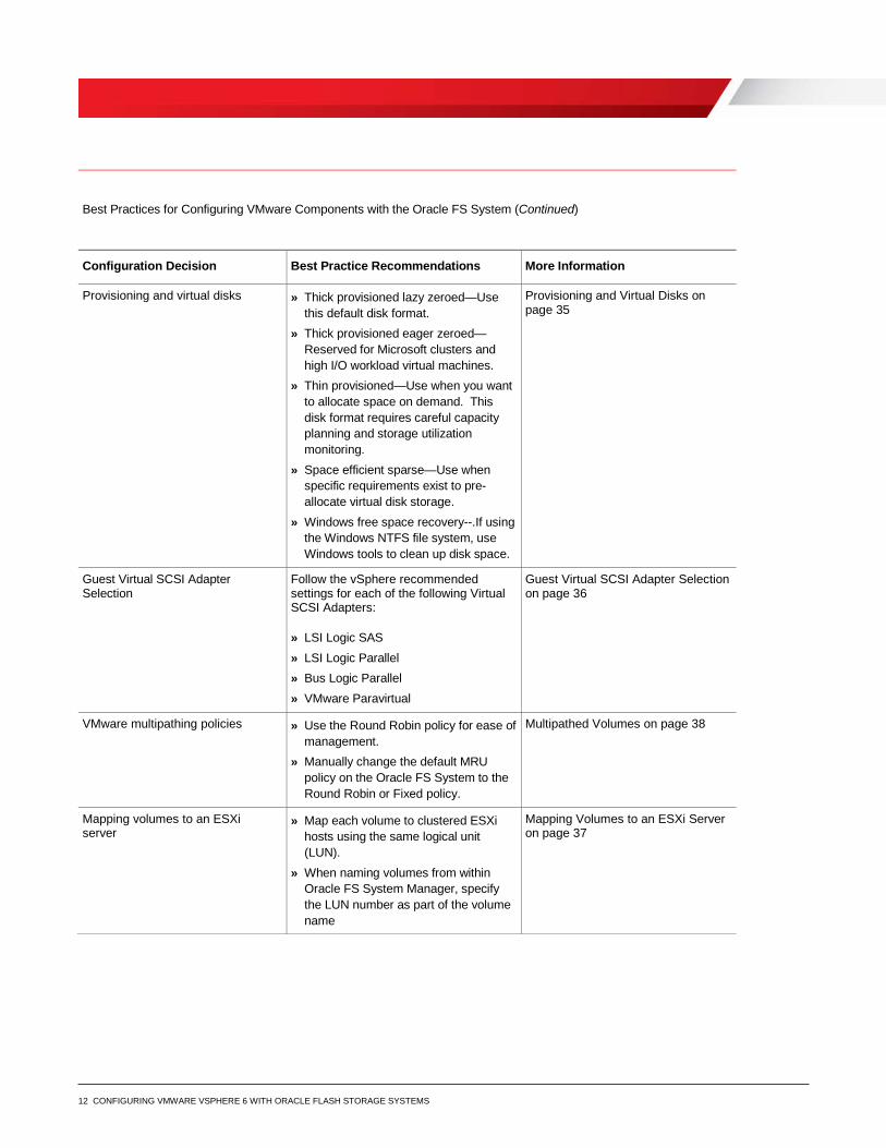
Best Practices for Configuring VMware Components with the Oracle FS System (Continued)
Configuration Decision Best Practice Recommendations More Information
Provisioning and virtual disks » Thick provisioned lazy zeroed—Use this default disk format.
» Thick provisioned eager zeroed—Reserved for Microsoft clusters and high I/O workload virtual machines.
» Thin provisioned—Use when you want to allocate space on demand. This disk format requires careful capacity planning and storage utilization monitoring.
» Space efficient sparse—Use when specific requirements exist to pre-allocate virtual disk storage.
» Windows free space recovery--.If using the Windows NTFS file system, use Windows tools to clean up disk space.
Provisioning and Virtual Disks on page 35
Guest Virtual SCSI Adapter Selection
Follow the vSphere recommended settings for each of the following Virtual SCSI Adapters: » LSI Logic SAS » LSI Logic Parallel » Bus Logic Parallel » VMware Paravirtual
Guest Virtual SCSI Adapter Selection on page 36
VMware multipathing policies » Use the Round Robin policy for ease of management.
» Manually change the default MRU policy on the Oracle FS System to the Round Robin or Fixed policy.
Multipathed Volumes on page 38
Mapping volumes to an ESXi server
» Map each volume to clustered ESXi hosts using the same logical unit (LUN).
» When naming volumes from within Oracle FS System Manager, specify the LUN number as part of the volume name
Mapping Volumes to an ESXi Server on page 37
13 CONFIGURING VMWARE VSPHERE 6 WITH ORACLE FLASH STORAGE SYSTEMS
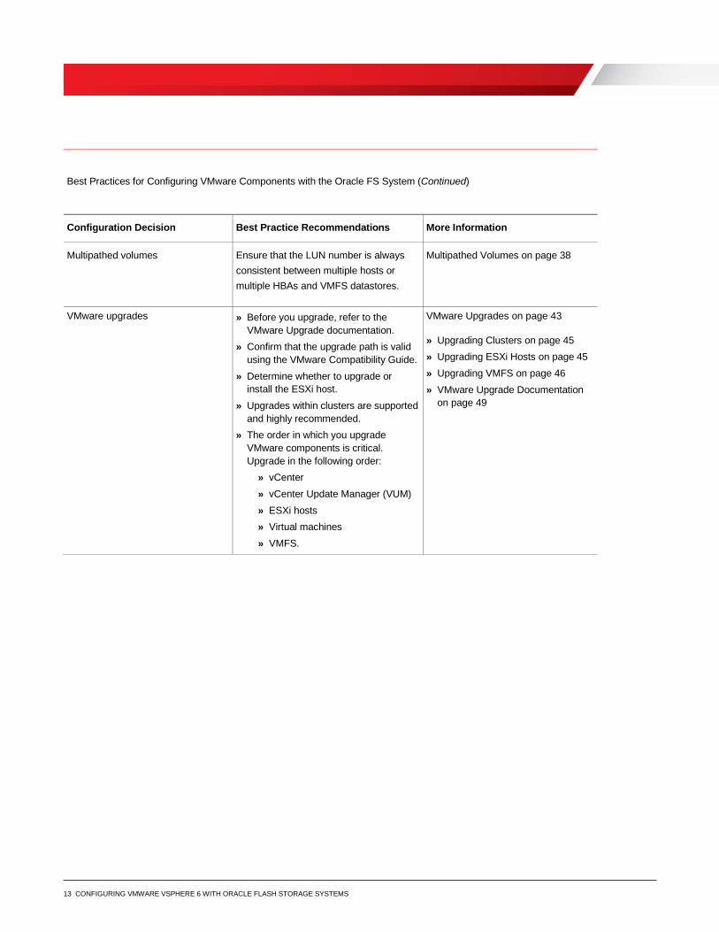
Best Practices for Configuring VMware Components with the Oracle FS System (Continued)
Configuration Decision Best Practice Recommendations More Information
Multipathed volumes Ensure that the LUN number is always consistent between multiple hosts or multiple HBAs and VMFS datastores.
Multipathed Volumes on page 38
VMware upgrades » Before you upgrade, refer to the VMware Upgrade documentation.
» Confirm that the upgrade path is valid using the VMware Compatibility Guide.
» Determine whether to upgrade or install the ESXi host.
» Upgrades within clusters are supported and highly recommended.
» The order in which you upgrade VMware components is critical. Upgrade in the following order:
» vCenter » vCenter Update Manager (VUM) » ESXi hosts » Virtual machines » VMFS.
VMware Upgrades on page 43 » Upgrading Clusters on page 45 » Upgrading ESXi Hosts on page 45 » Upgrading VMFS on page 46 » VMware Upgrade Documentation
on page 49
14 CONFIGURING VMWARE VSPHERE 6 WITH ORACLE FLASH STORAGE SYSTEMS
Design and Configuration
This section includes procedures you perform with Oracle FS System Manager, the ESXi host, or the vSphere Web Client.
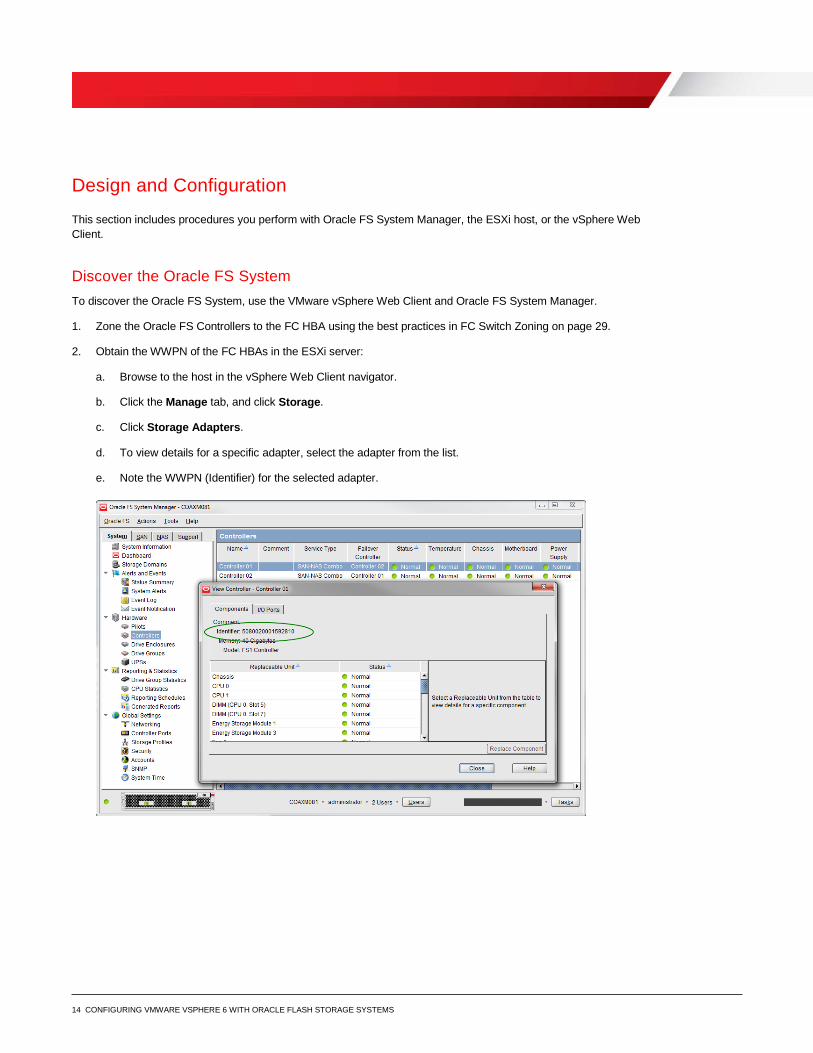
Discover the Oracle FS System To discover the Oracle FS System, use the VMware vSphere Web Client and Oracle FS System Manager.
1. Zone the Oracle FS Controllers to the FC HBA using the best practices in FC Switch Zoning on page 29.
2. Obtain the WWPN of the FC HBAs in the ESXi server:
a. Browse to the host in the vSphere Web Client navigator.
b. Click the Manage tab, and click Storage.
c. Click Storage Adapters.
d. To view details for a specific adapter, select the adapter from the list.
e. Note the WWPN (Identifier) for the selected adapter.
15 CONFIGURING VMWARE VSPHERE 6 WITH ORACLE FLASH STORAGE SYSTEMS
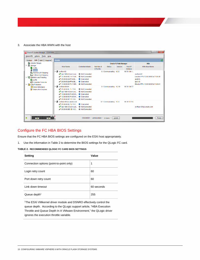
3. Associate the HBA WWN with the host
Configure the FC HBA BIOS Settings Ensure that the FC HBA BIOS settings are configured on the ESXi host appropriately.
1. Use the information in Table 2 to determine the BIOS settings for the QLogic FC card.
TABLE 2. RECOMMENDED QLOGIC FC CARD BIOS SETTINGS
Setting Value
Connection options (point-to-point only) 1
Login retry count 60
Port down retry count 60
Link down timeout 60 seconds
Queue depth1 255
1The ESXi VMkernel driver module and DSNRO effectively control the queue depth. According to the QLogic support article, “HBA Execution Throttle and Queue Depth In A VMware Environment,” the QLogic driver ignores the execution throttle variable.

16 CONFIGURING VMWARE VSPHERE 6 WITH ORACLE FLASH STORAGE SYSTEMS
2. Use the information in Table 3 to determine the BIOS settings for the Emulex FC card.
TABLE 3. RECOMMENDED EMULEX FC CARD BIOS SETTINGS
Setting Value
lpfc_devloss_tmo option 60 seconds
Topology (for auto-topology, point-to-point) 2
Queue depth1 255
1A queue depth of 255 allows the ESXi VMkernel driver module and DSNRO to more conveniently control the queue depth.
Queue Depth and Timeouts The queue depth determines the number of disk transactions the HBA accepts and processes between an initiator and a target. In this example, the initiator is a FC ESXi host HBA port. The target is the Oracle FS Controller Port.
Multiple initiators can send data to any given target. The initiator queue depth throttles the number of transactions sent to a target to prevent the target from flooding. When flooding occurs, transactions accumulate, causing higher latencies and degraded performance. Increasing the queue depth can sometimes increase performance. However, if the queue depth is set too high, the risk of overdriving the storage array increases.
Modify queue depth in the areas listed in Table 4.
CAUTION: The optimal queue depth on the host can vary for various reasons. As a best practice, only increase or decrease the queue depth when necessary.
TABLE 4. QUEUE DEPTH DEFAULT VALUES
Queue depth areas Setting
Application Depends on the application
Virtual SCSI card in the guest virtual machine Default = 32
Virtual Machine File System Layer (VMFS) DSNRO Default = 32
HBA VMKernel Module Driver Default = 64
HBA BIOS Default = 64

17 CONFIGURING VMWARE VSPHERE 6 WITH ORACLE FLASH STORAGE SYSTEMS
HBA Queue Depth
Consider the following when setting the queue depth on HBAs:
» Set the execution throttle or queue depth to 255. A queue depth value of 255 does not gate the driver module queue depth.
» The queue depth variable within the VMkernel driver module loaded for each HBA in the system and DSNRO ultimately regulate the host queue depth.
Set the Driver Queue Depth on FC HBAs
For the QLogic and Emulex HBAs, use the following steps to set the driver queue depth and timeouts.
1. Locate the appropriate driver name for the loaded module:
a. For QLogic, enter the following command:
esxcli system module list |grep ql
Output: qla2xxx or qlnativefc
b. For Emulex, enter the following command:
esxcli system module list |grep lpfc
Output: lpfc820
Note: The following steps contain example driver names. Use the drive names returned in step 1.
2. Using PuTTY and the esxcli command, set the driver queue depth and timeouts.
a. For QLogic, enter the following command:
esxcli system module parameters set -m qlnativefc -p "ql2xmaxqdepth=255
ql2xloginretrycount=60 qlport_down_retry=60"
b. For Emulex, enter the following command:
esxcli system module parameters set -m lpfc820 -p "lpfc_devloss_tmo=60
lpfc_hba_queue_depth=255"
Best Practice: In hosts with heavy workloads exceeding a 70% load factor (for example, with multipathing configurations), you can lower the qlport_down_retry value. Lowering the value decreases the failover times between paths.
3. Verify the HBA queue depth on the ESXi host using the following command:
esxcli system module parameters list –m=qlnativefc | more
18 CONFIGURING VMWARE VSPHERE 6 WITH ORACLE FLASH STORAGE SYSTEMS
Set the Queue Depth for the iSCSI Initiator
For the software iSCSI initiator, set the queue depth.
1. To set the queue depth to 255, use the following command:
esxcli system module parameters set -m iscsi_vmk -p iscsivmk_LunQDepth=255
2. Increase the login timeout to 30 seconds:
3. Determine the iSCSI adapter name:
esxcli iscsi adapter list
4. Set the login timeout parameter:
esxcli iscsi adapter param set –A vmhba3 –k LoginTimeout –v 60
5. For the change to take effect, reboot the ESXi host.
6. To verify the settings, use the following commands:
esxcli system module parameters list -m iscsi_vmk
esxcli iscsi adapter param get –A vmhba3
Storage Driver Queue Depth
The VMkernel driver module regulates the queue depth for the HBA if it needs to be modified. Refer to VMware vSphere Troubleshooting to configure these settings.
ESXi Host Queue Depth
For the following reasons, use caution when adjusting the queue depth on ESXi hosts:
» Increasing the queue depth can remove bottlenecks and help to improve performance. However, adequate back end spindles must exist to handle the incoming requests.
» If the queue depth is set improperly, the ESXi hosts could overdrive the Controller front end ports or the back end spindles and potentially worsen performance.
As a guideline, set the queue depth high enough to achieve an acceptable number of IOPS from the back end spindles. Do not set the queue depth so high that the ESXi host floods the front end or back end of the array. The following sections provide details.
FC Front End Ports Queue Depth
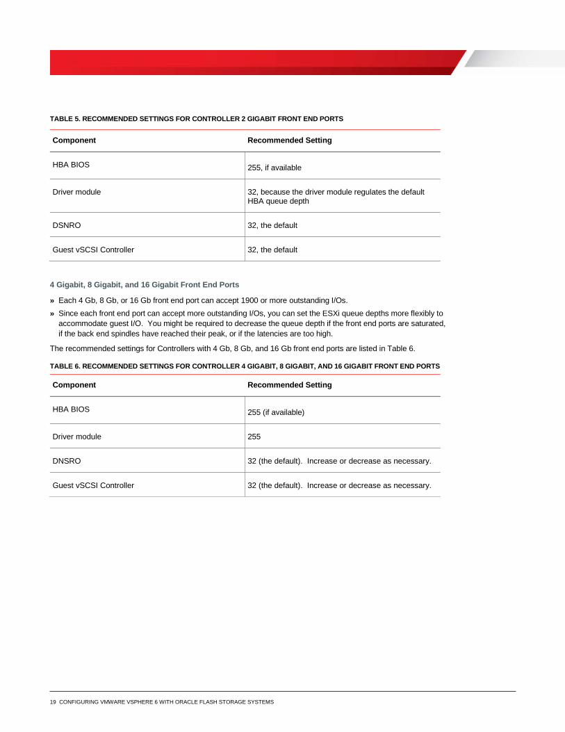
2-Gigabit Front End Ports
» The maximum queue depth for each 2-Gb front end port is 256. Do not exceed the maximum value. » Leave the ESXi queue depths set to default. Increase the queue depths only if necessary.
The recommended settings for Controllers with 2-Gb front end ports are listed in Table 5.
19 CONFIGURING VMWARE VSPHERE 6 WITH ORACLE FLASH STORAGE SYSTEMS
TABLE 5. RECOMMENDED SETTINGS FOR CONTROLLER 2 GIGABIT FRONT END PORTS
Component Recommended Setting
HBA BIOS 255, if available
Driver module 32, because the driver module regulates the default HBA queue depth
DSNRO 32, the default
Guest vSCSI Controller 32, the default
4 Gigabit, 8 Gigabit, and 16 Gigabit Front End Ports
» Each 4 Gb, 8 Gb, or 16 Gb front end port can accept 1900 or more outstanding I/Os. » Since each front end port can accept more outstanding I/Os, you can set the ESXi queue depths more flexibly to
accommodate guest I/O. You might be required to decrease the queue depth if the front end ports are saturated, if the back end spindles have reached their peak, or if the latencies are too high.
The recommended settings for Controllers with 4 Gb, 8 Gb, and 16 Gb front end ports are listed in Table 6.
TABLE 6. RECOMMENDED SETTINGS FOR CONTROLLER 4 GIGABIT, 8 GIGABIT, AND 16 GIGABIT FRONT END PORTS
Component Recommended Setting
HBA BIOS 255 (if available)
Driver module 255
DNSRO 32 (the default). Increase or decrease as necessary.
Guest vSCSI Controller 32 (the default). Increase or decrease as necessary.

20 CONFIGURING VMWARE VSPHERE 6 WITH ORACLE FLASH STORAGE SYSTEMS
iSCSI Queue Depth
With 1 Gb Oracle FS System front end ports, leave the queue depth set to the default and increase the queue depth only if necessary. With 10 Gb Oracle FS System front end ports, use the settings in Table 7.
TABLE 7. RECOMMENDED SETTINGS FOR 10-GIGABIT FRONT END PORTS WITH ISCSI
Component Recommended Setting
HBA BIOS if using hardware iSCSI 255
Driver Module • iscsi_vmk = 255 • DSNRO = 32 (default) Increase or decrease as necessary.
Guest vSCSI Controller 32 (the default). Increase or decrease as necessary.
ESXi Host Queue Depth
Although the per-LUN queue depth maximum is 256, the per-adapter maximum within ESXi is 4096. By increasing the per-LUN queue depth from 64 to 128, it takes fewer LUNs to saturate a port queue. For example, 4096/64=64 LUNs, but 4096/128=32 LUNs.
To determine the appropriate queue depth, use the esxtop utility.
You can execute the esxtop utility using one of the following methods:
» The ESXi Shell through SSH (command: esxtop) » The virtual CLI (vCLI) version 5.x » The resxtop or the resxtop.sh command on the vMA virtual appliance
Set the Queue Depth Using the Esxtop Utility
The esxtop utility enables you to see if the queue depth is set correctly and to coordinate the queue depth with the latency. When opening the esxtop utility, the best place to monitor queue depth and performance is from the Disk Device screen. To navigate to the screen, use the following steps:
1. To open the esxtop utility, use PuTTy.
2. From the command line, enter one of the following two options:
-# esxtop -resxtop.sh --server esxserver.domain.local
3. To open the Disk Device screen, press u.
4. To expand the devices field, type L 36 and press Enter. These actions expand the disk devices and the naa identifier can now identify the LUNs.

21 CONFIGURING VMWARE VSPHERE 6 WITH ORACLE FLASH STORAGE SYSTEMS
5. Press f and choose the fields to monitor:
a. To uncheck the ID field, press b (the ID is not required).
b. (Optional) Configure the following based on your preference:
i. Select i for overall latency.
ii. Select j for read latency.
iii. Select k for write latency.
c. To return to the monitoring screen, press Enter.
6. To set the refresh time to every two seconds, enter s 2 and press Enter.
If the LOAD is consistently greater than 1.00 on one or more volumes:
» The latencies are still acceptable. » The back end spindles have available IOPS, and increasing the queue depth might make sense.
If the LOAD is consistently less than 1.00 on most of the volumes, and the latencies are acceptable, you are not required to adjust the queue depth.
For more information about the disk statistics in esxtop, consult the esxtop man page or the vSphere Monitoring and Performance Guide.
Modifying the VMFS Queue Depth
Controlling the queue depth at the datastore level is an advanced setting within each ESXi host. The setting is named disk scheduled number requests outstanding (DSNRO).
You can increase or decrease the DSNRO value, depending on how many virtual machines you place on each datastore. You might also increase or decrease the value based on the virtual machine I/O requirements. This queue depth limit is only enforced when more than one virtual machine per host is active on that datastore.
If the value is set to the default, then the queue depth on the first virtual machine that is active on a datastore is limited. The limitation lies in the queue depth set in the VMkernel driver module. When a second, third, or fourth virtual machine is added to the datastore, the limit is enforced to the maximum queue depth of 32 during contention. The limit is also enforced when set by the esxcli storage core device command.
Note: The DSNRO limit does not apply to LUNs mapped as raw device mappings (RDMs). Each RDM has its own queue. You can modify the DSNRO setting on a per-datastore basis using the following command:
esxcli storage core device set -d <naa.dev> -O <value of 1-256>
Note: This command allows fine-tuning of DSNRO on a per-volume basis. If the desired queue depth is greater than 32, set the DSNRO value on each datastore and each host.
Globally Set the DSNRO
To set the DSNRO globally, use a scripting tool, such as the VMware PowerCLI utility.
This section provides an example script that sets the DSNRO to 64 globally across all datastores on each host. You can either rerun the script, or you can manually change any volume added after you run this script.
22 CONFIGURING VMWARE VSPHERE 6 WITH ORACLE FLASH STORAGE SYSTEMS
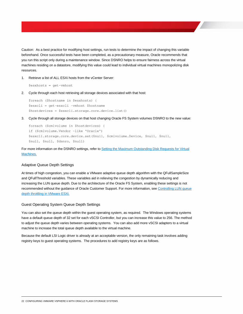
Caution: As a best practice for modifying host settings, run tests to determine the impact of changing this variable beforehand. Once successful tests have been completed, as a precautionary measure, Oracle recommends that you run this script only during a maintenance window. Since DSNRO helps to ensure fairness across the virtual machines residing on a datastore, modifying this value could lead to individual virtual machines monopolizing disk resources.
1. Retrieve a list of ALL ESXi hosts from the vCenter Server:
$esxhosts = get-vmhost
2. Cycle through each host retrieving all storage devices associated with that host:
foreach ($hostname in $esxhosts) {
$esxcli = get-esxcli -vmhost $hostname
$hostdevices = $esxcli.storage.core.device.list()
3. Cycle through all storage devices on that host changing Oracle FS System volumes DSNRO to the new value:
foreach ($cmlvolume in $hostdevices) {
if ($cmlvolume.Vendor -like "Oracle")
$esxcli.storage.core.device.set($null, $cmlvolume.Device, $null, $null,
$null, $null, $dsnro, $null)
For more information on the DSNRO settings, refer to Setting the Maximum Outstanding Disk Requests for Virtual Machines.
Adaptive Queue Depth Settings
At times of high congestion, you can enable a VMware adaptive queue depth algorithm with the QFullSampleSize and QFullThreshold variables. These variables aid in relieving the congestion by dynamically reducing and increasing the LUN queue depth. Due to the architecture of the Oracle FS System, enabling these settings is not recommended without the guidance of Oracle Customer Support. For more information, see Controlling LUN queue depth throttling in VMware ESXi.
Guest Operating System Queue Depth Settings
You can also set the queue depth within the guest operating system, as required. The Windows operating systems have a default queue depth of 32 set for each vSCSI Controller, but you can increase this value to 256. The method to adjust the queue depth varies between operating systems. You can also add more vSCSI adapters to a virtual machine to increase the total queue depth available to the virtual machine.
Because the default LSI Logic driver is already at an acceptable version, the only remaining task involves adding registry keys to guest operating systems. The procedures to add registry keys are as follows.
23 CONFIGURING VMWARE VSPHERE 6 WITH ORACLE FLASH STORAGE SYSTEMS
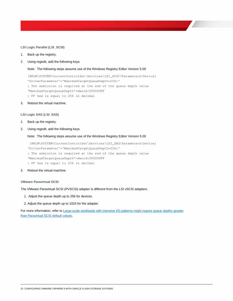
LSI Logic Parallel (LSI_SCSI)
1. Back up the registry.
2. Using regedit, add the following keys.
Note: The following steps assume use of the Windows Registry Editor Version 5.00
[HKLM\SYSTEM\CurrentControlSet\Services\LSI_SCSI\Parameters\Device]
"DriverParameter"="MaximumTargetQueueDepth=256;"
; The semicolon is required at the end of the queue depth value
"MaximumTargetQueueDepth"=dword:000000FF
; FF hex is equal to 256 in decimal
3. Reboot the virtual machine.
LSI Logic SAS (LSI_SAS)
1. Back up the registry.
2. Using regedit, add the following keys.
Note: The following steps assume use of the Windows Registry Editor Version 5.00
[HKLM\SYSTEM\CurrentControlSet\Services\LSI_SAS\Parameters\Device]
"DriverParameter"="MaximumTargetQueueDepth=256;"
; The semicolon is required at the end of the queue depth value
"MaximumTargetQueueDepth"=dword:000000FF
; FF hex is equal to 256 in decimal
3. Reboot the virtual machine.
VMware Paravirtual SCSI
The VMware Paravirtual SCSI (PVSCSI) adapter is different from the LSI vSCSI adapters.
1. Adjust the queue depth up to 256 for devices.
2. Adjust the queue depth up to 1024 for the adapter.
For more information, refer to Large-scale workloads with intensive I/O patterns might require queue depths greater than Paravirtual SCSI default values.
24 CONFIGURING VMWARE VSPHERE 6 WITH ORACLE FLASH STORAGE SYSTEMS
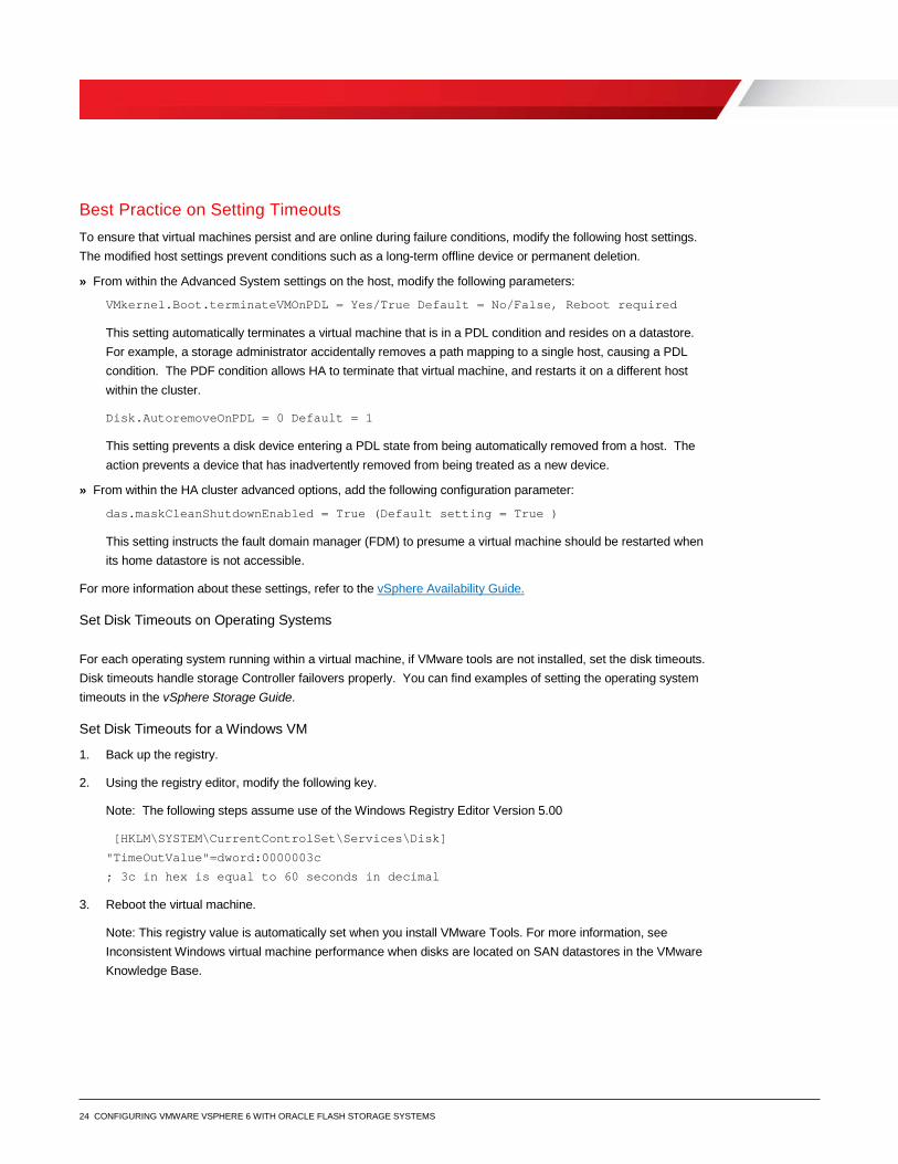
Best Practice on Setting Timeouts To ensure that virtual machines persist and are online during failure conditions, modify the following host settings. The modified host settings prevent conditions such as a long-term offline device or permanent deletion.
» From within the Advanced System settings on the host, modify the following parameters:
VMkernel.Boot.terminateVMOnPDL = Yes/True Default = No/False, Reboot required
This setting automatically terminates a virtual machine that is in a PDL condition and resides on a datastore. For example, a storage administrator accidentally removes a path mapping to a single host, causing a PDL condition. The PDF condition allows HA to terminate that virtual machine, and restarts it on a different host within the cluster.
Disk.AutoremoveOnPDL = 0 Default = 1
This setting prevents a disk device entering a PDL state from being automatically removed from a host. The action prevents a device that has inadvertently removed from being treated as a new device.
» From within the HA cluster advanced options, add the following configuration parameter:
das.maskCleanShutdownEnabled = True (Default setting = True )
This setting instructs the fault domain manager (FDM) to presume a virtual machine should be restarted when its home datastore is not accessible.
For more information about these settings, refer to the vSphere Availability Guide.
Set Disk Timeouts on Operating Systems
For each operating system running within a virtual machine, if VMware tools are not installed, set the disk timeouts. Disk timeouts handle storage Controller failovers properly. You can find examples of setting the operating system timeouts in the vSphere Storage Guide.
Set Disk Timeouts for a Windows VM
1. Back up the registry.
2. Using the registry editor, modify the following key.
Note: The following steps assume use of the Windows Registry Editor Version 5.00
[HKLM\SYSTEM\CurrentControlSet\Services\Disk]
"TimeOutValue"=dword:0000003c
; 3c in hex is equal to 60 seconds in decimal
3. Reboot the virtual machine.
Note: This registry value is automatically set when you install VMware Tools. For more information, see Inconsistent Windows virtual machine performance when disks are located on SAN datastores in the VMware Knowledge Base.
25 CONFIGURING VMWARE VSPHERE 6 WITH ORACLE FLASH STORAGE SYSTEMS
Set Disk Timeouts for a Linux VM
Starting with Linux 2.6.13 kernels, you can set the timeout value for a Linux block device using the sysfs interface. This fix does not affect kernels below 2.6.13.
1. Check the current timeout for every generic SCSI device in Linux sysfs using the command:
find /sys/class/scsi_generic/*/device/timeout -exec grep -H . '{}' \;
2. Modify the timeout value for an individual disk using the sysfs interface. For example:
echo 180 > /sys/block/ sdc/device/timeout
Note: This change does not persist across reboots.
Refer to Increasing the disk timeout values for a Linux 2.6 virtual machine for more information.
Configure the iSCSI Initiator You configure the VMware iSCSI software initiator using both the VMware vSphere Web Client and Oracle FS System Manager.
For more information, refer to Configuring iSCSI Adapters and Storage.
1. From within the VMware vSphere Web Client, enable the software iSCSI client.
The software iSCSI client resides within the ESXi firewall in the security profile of the ESXi host.
2. Add a VMkernel port to a virtual switch assigned to the physical NIC for iSCSI.
3. From the Storage Adapters configuration screen, click the plus sign (+) to add an adapter. Then, select Software iSCSI Adapter, and click OK.
4. In the Storage Adapters area, highlight the iSCSI software adapter (for example, vmhba38).
5. To add the Oracle FS front end ports, select Targets, then select the Dynamic Discovery tab.
6. Click Add, and then enter the IP address for the iSCSI control port.
The IP address is labeled as the Well Known IP Address for the Fault Domain.
Note: If virtual ports are not enabled for iSCSI front end ports, manually add each of the iSCSI adapter IP addresses for the system.
7. Rescan the iSCSI initiator.
8. From within Oracle FS System Manager, create a server object for the ESXi host.
9. Map a volume to the ESXi host.
10. From within the VMware vSphere Web Client, navigate to the Storage Adapters configuration screen and rescan the iSCSI HBA for new volumes.
26 CONFIGURING VMWARE VSPHERE 6 WITH ORACLE FLASH STORAGE SYSTEMS
Configure the iSCSI Initiator To configure the VMware iSCSI software initiator for multipathing, see sections “Configuring Software iSCSI Adapter” and “Multiple Network Adapters in iSCSI Configuration” in the vSphere Storage Guide.
If you have previous experience configuring iSCSI for multipathing, perform the following tasks.
» Verify that there is one VMkernel interface for each physical NIC to be used for storage traffic. Make sure that the physical NICs follow the virtual switch port binding recommendations listed in Virtual Switch Recommendations for iSCSI Port Binding on page 26.
» Adjust the failover order on each VMkernel interface for a 1-to-1 VMkernel-to-physical NIC ratio. » Add both VMkernel interfaces to the iSCSI software adapter network port binding. If you have not set the
prerequisite failover orders, the vSphere Web Client does not allow the operation. » Rescan the iSCSI software adapter for new volumes.
Virtual Switch Recommendations
Avoid using port binding when the VMkernel ports are on different networks. VMkernel ports on different networks could cause excessive rescan times and other storage management problems. When subnets have different IP addressing schemes, the vSwitches can cause problems.
1. Using traditional one-to-one mapping, configure the physical network with a single subnet for iSCSI and a single vSwitch with two iSCSI virtual ports.
You can use more iSCSI virtual ports if more front end ports exist on the Controller.
2. With subnet 10.10.x.x and subnet mask 255.255.0.0, create the vSwitch.
For more information about software iSCSI port binding in the ESXi host, refer to http://kb.vmware.com/kb/2038869
Multi-VLAN Recommendations
» Use multiple-VLAN support for diverse network configurations and multi-tenant environments. » Multiple VLANs allow iSCSI storage I/O to be separated between vSwitches for customers using software iSCSI
initiators within the guest. You can also use multiple VLANs to isolate ESXi host-cluster VMkernel ports to their own dedicated iSCSI storage VLAN.
» Since iSCSI traffic is not encrypted in its plain form, isolate that traffic for security purposes. The Challenge-Handshake Authentication Protocol (CHAP) does not encrypt iSCSI traffic, it only provides authentication for the connection to prevent unauthorized access.
» To optimize performance, enable jumbo frames on a per domain basis.
27 CONFIGURING VMWARE VSPHERE 6 WITH ORACLE FLASH STORAGE SYSTEMS
Adjust the Claim Rules on the ESXi Host
When using the ESXi software FCoE, LUNs are assigned to the VMW_SATP_LOCAL by default. In some instances, this LUN assignment causes paths to go unclaimed. To remedy this situation, you can adjust the claim rules on each ESXi host so that FCoE volumes are correctly assigned to the VMW_SATP_DEFAULT_ALUA.
To adjust the claim rules on each ESXi host, use the following command:
[root@co-solsunx5-06:~] esxcli storage nmp satp rule add -R fcoe -s VMW_SATP_ALUA
Unmap Volumes from an ESXi Host Within the ESXi host, VMware has added the ability to detach volumes gracefully before unmapping them. Detaching volumes prevents an all-paths down (APD) state.
Before attempting this procedure, consult Performing Planned Storage Device Removal in the vSphere Storage Guide.
1. Browse to the host in the vSphere Web Client navigator.
2. From the Manage tab, click Settings.
3. Select Connectivity and Multipathing.
Note the Oracle FC Disk naa identifier. The naa identifier is referenced later.
4. From the datastore view, right-click the datastore.
5. From the Actions list, select Unmount Datastore.
6. Once the datastore has been successfully unmounted, select Detach on the disk device.
7. Repeat step 1 through step 3 for each host the volume is presented.
8. Within Oracle FS System Manager, unmap the volume.
9. Within the vSphere Web Client, rescan the adapters to ensure that the disk has been detached.
Extend VMware Volumes Within an ESXi host, you can extend storage using one of the following methods:
» Expand an existing extent of the VMFS datastore » Add an extent to the VMFS datastore » Increase the size of the virtual machine disk (VMDK) file
To increase the size of VMFS datastores, you can expand an existing extent (recommended) or add an extent (not recommended).
28 CONFIGURING VMWARE VSPHERE 6 WITH ORACLE FLASH STORAGE SYSTEMS
Increase VMFS Datastore Capacity
This section provides the general steps required to increase VMFS datastore capacity. You can find additional information in the vSphere Storage Guide and the vSphere Administration with the vSphere Client. Find both documents at VMware vSphere 6 Documentation
When you add virtual machines to a datastore, or when the virtual machines running on a datastore require more space, you can dynamically increase the capacity of a VMFS datastore.
If a shared datastore has powered on virtual machines and becomes 100% full, you can increase the capacity of the datastore. You increase the capacity from the host on which the powered-on virtual machines are registered.
1. In the vSphere Web Client navigator, select vCenter Inventory Lists > Datastores.
2. Select the datastore to grow and click the Increase Datastore Capacity icon.
3. Select a device from the list of storage devices.
Your selection depends on whether an expandable storage device is available.
• To expand an existing extent, select the device for which the Expandable column reads YES. A storage device is reported as expandable when it has free space immediately after the extent.
• To add an extent, select the device for which the Expandable column reads NO.
4. Review the current disk layout to see the available configurations, and then click Next.
5. Select a configuration option from the bottom panel.
Depending on the current layout of the disk and on your previous selections, the options you see might vary.
6. Set the capacity for the extent.
The minimum extent size is 1.3 GB. By default, the entire free space on the storage device is available.
7. Click Next.
8. Review the proposed layout and the new configuration of your datastore, and click Finish.
Increasing the Size of a VMDK File
You can hot-extend a SCSI virtual disk from within the vSphere Web Client. After extending the virtual disk from the vSphere Web Client, complete the following steps:
1. Log in to the virtual machine.
2. Rescan for new disks.
3. Extend the file system.
For instructions, refer to the specific operating system vendor instructions. Limitations might exist. For example, Microsoft does not support extending the system partition of a machine in Windows 2008 or earlier versions of Windows.
29 CONFIGURING VMWARE VSPHERE 6 WITH ORACLE FLASH STORAGE SYSTEMS
VMware and Oracle Storage Options The following sections discuss best practice details for storage options in a virtual data center.
FC Switch Zoning
Zoning FC switches for an ESXi host is similar to zoning any other operating system connected to the FS System.
Single Initiator Zoning
Configure each FC zone with a single initiator (HBA port) and multiple targets (FS Controller ports):
» Each HBA port requires its own FC zone that contains itself and the FS System Controller ports. » Create independent zones for each HBA installed in the host.
WWN Zoning
When zoning by World Wide Name (WWN), the zone must contain the host HBA port and the Oracle FS Controller ports.
For example, if the host has two HBAs connected to two disjointed fabrics, the FC zones look similar to the configuration shown in Table 8.
TABLE 8. EXAMPLE OF ZONING BY WWN
Name WWN Description
ESXHost-HBA1-Port1 Zone Created in Fabric 1
2100001D82017118 Port 1 of 2 port HBA
508002000158C190 Oracle FS1 Storage Controller 1 WWPN
508002000158C191 Oracle FS1 Storage Controller 2 WWPN
ESXHost-HBA1-Port2 Zone Created in Fabric 2
2100001D82017119 Port 2 of 2 port HBA
508002000158C190 Oracle FS1 Storage Controller 1 WWPN
508002000158C191 Oracle FS1 Storage Controller 2 WWPN
Port Zoning
Port zoning is more secure than zoning by WWN, but port zoning is complex and can introduce support and scalability problems. For these reasons, Oracle recommends zoning by WWN.
Virtual Ports
If using virtual port mode, include all the front end virtual ports within the Open Virtual Network (OVN).
30 CONFIGURING VMWARE VSPHERE 6 WITH ORACLE FLASH STORAGE SYSTEMS
Boot ESXi Hosts from SAN The decision to boot from SAN depends on many factors, including cost, data protection, and configuration requirements. In some cases, such as with blade servers that do not have internal disk drives, booting from SAN might be the only option. However, many ESXi hosts can have internal mirrored drives, providing the flexibility of choice. Booting from SAN alleviates the need for internal drives and allows the ability to take replays of the boot volume.
When deciding to boot ESXi hosts from SAN, consider the following best practices:
» When mapping the boot volume to the ESXi host for the initial install, the boot volume should only be mapped down a single path to a single HBA.
» Once the ESXi host has been loaded and multipath modules are operating correctly, you can add the second path to the boot volume.
» Before you boot ESXi hosts from SAN, determine the following settings: » The optimal number of virtual machines per datastore. » The file system versions for your environment.
Volume Sizing Although you can present a maximum of LUN size of 64 TB to an ESXi host, Oracle recommends that you configure smaller, more manageable datastores. Start in the 500--750 GB range and expand as needed. For example, a 750-GB datastore accommodates approximately 15 virtual disks with 40-GB on each virtual disk. This configuration leaves a small amount of overhead for virtual machine configuration files, logs, snapshots, and memory swap. These sizing recommendations limit the number of virtual machines on each datastore and the performance of the datastore is not compromised.
Virtual Machines per Datastore A good, conservative approach is to place between eight and 16 virtual machines on each datastore. In addition to the number of virtual machines per datastore, limit the datastore size to 4 TB. By limiting the size of the datastore, you also limit the total number of virtual machines that can be placed on each datastore.
Note: You can move virtual machines between datastores non-disruptively using the VMware Storage vMotion feature. A license is required.
The disk load influences the optimal number of virtual machines on each datastore. The queue depth is a strong indicator that too many virtual machines are placed on the datastore. If the datastore regularly exceeds set limits, disk latency increases. If the driver module is set to a queue depth of 256, the maximum queue depth of each datastore is also 256.
As an example, if 16 virtual machines exist on a datastore and heavily drive a 32 queue depth, the virtual machines are overdriving the disk queues by double. The resulting high latency most likely degrades performance.
31 CONFIGURING VMWARE VSPHERE 6 WITH ORACLE FLASH STORAGE SYSTEMS
LUN Mapping Layout In addition to volume sizing, another important factor includes the placement of files and the virtual machine data.
Multiple Virtual Machines per LUN
One of the most common techniques in virtualization is to place more than one virtual machine on each volume. This placement allows for the encapsulation of virtual machines and results in higher consolidation ratios.
When deciding how to lay out the VMFS volumes and virtual disks, consider the performance, application, and backup requirements of the guest operating systems, for example:
» Storage of non-virtual machine files
Create a content library or a datastore for administrative items. Use the content library or datastore to store virtual machine templates, International Standards Organization (ISO) images, virtual floppies, and scripts.
» Separation of operating system page files
When memory swapping, place the operating system paging files or swap files onto a separate datastore. This practice provides the following benefits:
» Page files can generate excessive disk activity. When the memory in the virtual machine or ESXi host runs low, this practice results in smaller volume replays.
» When replicating volumes, separating operating system page files conserves bandwidth by not replicating the operating system page file data.
Depending on the memory-swap conditions unique to each environment, separating page files might or might not reduce replay sizes. Monitor the swap and balloon usage of the ESXi host. If these numbers are high, consider testing the separation of page files to determine the actual impact.
If you determine that separating page files reduces replay sizes, create pairs of volumes for each datastore containing virtual machines. If you create a volume to contain 10 virtual machines, then create a second volume to store the operating system page files for those 10 machines. For example:
» Create one datastore for virtual machines. The datastore usually contains the virtual machine disk (VMDK) files, configuration files, and logs for the virtual machines.
» Create one paired datastore for the corresponding virtual machine page files. The paired datastore should contain virtual machine page files. Using Windows as an example, create a virtual disk on this volume large enough to store the Windows paging file for each virtual machine. This volume can be sized considerably smaller than the main datastore since it only needs enough space to store page files.
32 CONFIGURING VMWARE VSPHERE 6 WITH ORACLE FLASH STORAGE SYSTEMS
Page Files on Separate Datastores
Avoid putting all the operating system page files on a single datastore. This is not a good practice for the following reasons.
» The page file datastore can experience contention from queue depth utilization or disk I/O. Too many VMDK files during a sudden memory-swapping event could decrease performance even further. For example, if a node in the ESXi high availability (HA) cluster fails and the effected virtual machines are consolidated on the remaining hosts. The sudden reduction in overall memory could cause a sudden increase in paging activity that could overload the datastore, causing a storage performance decrease.
» A single datastore could become a single point of failure. Operating systems are not tolerant of unexpected disk-drive removal. If you unmap the page file volume inadvertently, the number of virtual machines within the failure domain are isolated to a subset of the virtual machines rather than all the virtual machines.
Separation of Virtual Machine Swap Files
Each virtual machine has a memory swap file located in its home directory. The virtual machine swap (VSWP) file is used by the ESXi host when the VMware Tools balloon driver is unable to reclaim enough memory. The ESXi host generally uses the VSWP file as a last resort to reclaim memory.
VMware recommends keeping the VSWP files located in the virtual machine home directories. You can relocate the VSWP file to a dedicated LUN to reduce replay sizes and preserve replication bandwidth. However, only alter the VSWP file under the guidance of VMware support.
VMFS Partition Alignment The VMFS is a high performance cluster file system that allows virtualization to scale beyond the boundaries of a single system. Partition alignment is a performance-tuning technique used with traditional SANs. Partition alignment aligns the guest OS partitions and the VMFS partitions to the physical media. This action reduces the number of required disk transactions required to process an I/O operation.
To align the VMFS block boundaries manually to the Oracle FS System page boundaries, Oracle recommends an 8192 byte datastore size.
» VMFS-3 file system » If any remaining VMFS-3 datastores exist in the environment, create VMFS-5 datastores, and migrate the
virtual machines to the VMFS-3 datastores using Storage vMotion (license required). » Before upgrading a VMFS-3 datastore to VMFS-5, Oracle recommends that you take a replay of the VMFS-3
datastore for protection against any possible loss of data. » VMFS-5 file system
» You create datastores using the VMware vSphere Web Client. Select VMFS-5 as the file system type. » With the VMFS-5 file system, the only available block size is 1 MB, allowing for up to a 64 TB datastore (up
to a 62 TB VMDK). This format is required for functionality such as the VAAI space reclamation primitive (SCSI UNMAP) to reclaim the VMFS-3 file system.
33 CONFIGURING VMWARE VSPHERE 6 WITH ORACLE FLASH STORAGE SYSTEMS
Adding a New VMFS Extent to an Existing Datastore
VMFS extents were previously used in vSphere to concatenate multiple volumes to create VMFS-3 datastores. Since the maximum datastore size with VMFS-5 is increased to 64 TB, extents are no longer necessary.
CAUTION: The use of VMFS extents is highly discouraged. Coordinating replays and datastore recoveries that are spanned across multiple Oracle FS System volumes is complex.
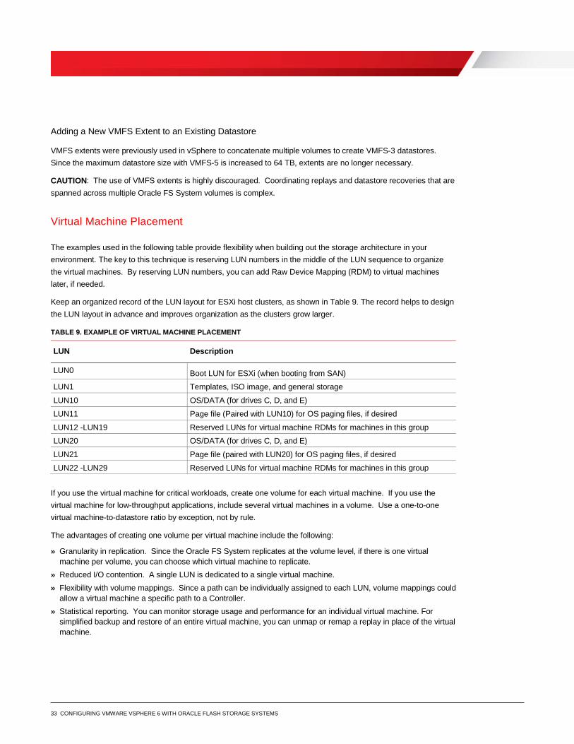
Virtual Machine Placement
The examples used in the following table provide flexibility when building out the storage architecture in your environment. The key to this technique is reserving LUN numbers in the middle of the LUN sequence to organize the virtual machines. By reserving LUN numbers, you can add Raw Device Mapping (RDM) to virtual machines later, if needed.
Keep an organized record of the LUN layout for ESXi host clusters, as shown in Table 9. The record helps to design the LUN layout in advance and improves organization as the clusters grow larger.
TABLE 9. EXAMPLE OF VIRTUAL MACHINE PLACEMENT
LUN Description
LUN0 Boot LUN for ESXi (when booting from SAN)
LUN1 Templates, ISO image, and general storage
LUN10 OS/DATA (for drives C, D, and E)
LUN11 Page file (Paired with LUN10) for OS paging files, if desired
LUN12 -LUN19 Reserved LUNs for virtual machine RDMs for machines in this group
LUN20 OS/DATA (for drives C, D, and E)
LUN21 Page file (paired with LUN20) for OS paging files, if desired
LUN22 -LUN29 Reserved LUNs for virtual machine RDMs for machines in this group
If you use the virtual machine for critical workloads, create one volume for each virtual machine. If you use the virtual machine for low-throughput applications, include several virtual machines in a volume. Use a one-to-one virtual machine-to-datastore ratio by exception, not by rule.
The advantages of creating one volume per virtual machine include the following:
» Granularity in replication. Since the Oracle FS System replicates at the volume level, if there is one virtual machine per volume, you can choose which virtual machine to replicate.
» Reduced I/O contention. A single LUN is dedicated to a single virtual machine. » Flexibility with volume mappings. Since a path can be individually assigned to each LUN, volume mappings could
allow a virtual machine a specific path to a Controller. » Statistical reporting. You can monitor storage usage and performance for an individual virtual machine. For
simplified backup and restore of an entire virtual machine, you can unmap or remap a replay in place of the virtual machine.
34 CONFIGURING VMWARE VSPHERE 6 WITH ORACLE FLASH STORAGE SYSTEMS
Raw Device Mapping RDMs are used to map a LUN directly to a virtual machine. When an RDM that is set to physical compatibility mode is mapped to a virtual machine, the operating system writes directly to the volume and bypasses VMFS file system.
RDM is recommended for high performance, mission-critical application workloads. RDM is not recommended for less critical applications, where virtual disks provide all the benefits.
Advantages of Using RDMs
» You can map virtual mode RDMs (vRDMs) up to 62 TB and physical mode RDMs (pRDMs) up to 64 TB directly to a guest OS.
» vRDMs support vSphere snapshots. » You can create a clustered resource, such as Microsoft Cluster Services, with the following mapping options:
» Virtual machine to virtual machine » Virtual machine to physical machine
» You can map the volume to another physical server in the event of a disaster or recovery. » You can convert physical machines to virtual machines more easily because a physical machine volume can be
mapped as an RDM. » When a virtual machine has special disk performance needs:
» The disk performance might increase when using an RDM versus a VMFS virtual disk. The improved performance is due to the lack of contention, no VMFS write penalties, and better queue depth utilization.
» Independent disk queues can exist per RDM. » A different storage profile can be assigned to each volume. For example, if a database server has its
database and logs separated on to different volumes, each can have a separate storage profile. » A different replay profile can be used with each volume. For example, a database and its transaction logs
can have different replay intervals and retention periods for expiration.
Disadvantages of Using RDMs
» RDMs can add administrative overhead with large numbers of mappings. » Only a limited number of LUNs can be mapped to an ESXi host. If every virtual machine used RDMs for drives,
then the cluster would have a maximum number of 255 drives. » Physical mode RDMs cannot be used with ESXi snapshots. Although VMware snapshots are not available for
physical mode RDMs, you can use Oracle FS cloning and LUN Copies to save RDM data.
35 CONFIGURING VMWARE VSPHERE 6 WITH ORACLE FLASH STORAGE SYSTEMS
Increase the Size of an RDM
You can extend a physical mode RDM on which a VMDK resides on a VMFS-5 datastore up to the 64 TB limit. Depending on the version, virtual RDMs, however, are limited to anywhere between 2 TB to 62 TB.
Caution: As with datastore volumes, do not extend an RDM volume with its pointer file residing on a VMFS-3 datastore past the 1.99 TB limit. Exceeding the limit causes catastrophic and undefined behavior, including data loss.
To extend a raw device mapping, follow the same basic procedure as with a physical server:
1. Extend the RDM volume from within Oracle FS System Manager.
2. Rescan disks from Windows disk management.
3. To extend the drive, use DISKPART or the Storage MMC console.
Replication of VSS-Aware Applications
Use the Microsoft Windows Volume Shadow Copy Service (VSS) framework for replication of applications. VSS-aware applications include Microsoft Active Directory (AD), Microsoft SQL Server, Microsoft Exchange, or Oracle. The VSS software package ensures that the application data is in a consistent state before executing the replay. An example of how scripting utilities are used is to take a replay of an Oracle database after the database is in hot-backup mode.
Provisioning and Virtual Disks Oracle FS thin provisioning allows less storage to be consumed for virtual machines, which saves up-front storage costs. This section describes the relationship that this feature has with virtual machine storage.
The VMFS on the ESXi 6.x host can store virtual disks using one of the following virtual disk formats:
» Thick provision lazy zeroed
Use the thick provision lazy zeroed disk format, which is the default. Specific requirements might exist where it is necessary to pre-allocate virtual disk storage, for example:
» Microsoft clustering » VMware Fault Tolerance (FT) » Virtual machines impacted by the thin or zeroed thick on-first-write penalties. » Applications that are sensitive to VMFS write penalties
In these configurations, Oracle recommends you test eager zeroed thick virtual disks to determine the actual performance impact.
36 CONFIGURING VMWARE VSPHERE 6 WITH ORACLE FLASH STORAGE SYSTEMS
» Thick provision eager zeroed
When the virtual disk is created, the required space is fully allocated. Disks in this format could take longer to create than other types of disks because all the blocks must be zeroed out before the disks can be used. When using vStorage API for Array Integration (VAAI), however, the time it takes to create an eager zeroed thick disk is greatly reduced. The thick provision eager zeroed format is reserved for Microsoft clusters and the highest-I/O-workload virtual machines. This format does not suffer from operational write penalties like the thick provisioned-lazy zeroed or thin formats.
» Thin provision
The logical space required for the virtual disk is not allocated during creation. Logical space is allocated on demand during the first write issued to the block. As with thick disks, the thin provision format also zeros out the block before writing data. This action induces extra I/O and an extra amount of write latency.
When you want to allocate space on demand to reduce management overhead, use thin-provisioning. Thin-provisioning requires careful capacity planning and storage utilization monitoring. To prevent accidentally overwriting the allocated storage, use the built-in vSphere datastore threshold alerting capabilities which warn against running out of space on a datastore.
» Space efficient sparse disks
Space efficient (SE) sparse disks are a new virtual disk type introduced for use with VMware Horizon View Composer. These virtual disks are used with linked clones for improved performance, space reclamation, and a new 4 KB grain size.
» Windows free space recovery
With the Windows NTFS file system, the actual usage of the file system can gradually grow apart from what the Oracle FS System reports as allocated. In this example, there is a 20-GB data volume where Windows writes 15-GB worth of files, followed by deleting 10-GB worth of those files. Although Windows reports only 5-GB of disk space in-use, dynamic capacity has assigned those blocks to that volume. The Oracle FS System still reports 15-GB of used data. When Windows deletes a file, it removes the entry in the file allocation table. No built-in mechanisms exist for the Oracle FS System to determine if an allocated block is still in use by the OS. If you use the Windows NTFS file system, then use the tools that exist within the Windows OS to clean up disk space.
Guest Virtual SCSI Adapter Selection When creating a virtual machine, you can choose from four types of virtual SCSI (vSCSI) adapters. vSphere automatically selects and recommends a vSCSI adapter that is best suited for the selected operating system. Follow the vSphere recommendation. The nuances of each vSCSI adapter are as follows.
» LSI Logic SAS
The LSI Logic SAS adapter is available for virtual machines with hardware versions 7 and later. This adapter adds support for SCSI-3 reservations, which are required for Microsoft Cluster Services (MSCS). The adapter is preferred, as operating system vendors are gradually withdrawing support for SCSI in favor of SAS.
37 CONFIGURING VMWARE VSPHERE 6 WITH ORACLE FLASH STORAGE SYSTEMS
» LSI Logic Parallel
Many OS versions support the LSI Logic Parallel adapter. However, the LSI Logic Parallel adapter is recommended only for virtual machines that do not support the LSI Logic SAS adapter.
» Bus Logic Parallel
A queue depth limitation exists for the Bus Logic Parallel adapter. The limitation results in poor performance and therefore this adapter is not recommended.
» VMware Paravirtual
This high-performance vSCSI adapter can result in greater throughput and lower CPU utilization. Due to feature limitations, do not use the VMware Paravirtual adapter unless the virtual machine has specific performance needs.
For more information about the limitations of this adapter in the section, refer to About VMware Paravirtual SCSI Controllers in the vSphere Virtual Machine Administration Guide.
Mapping Volumes to an ESXi Server Mapping is the process of presenting an Oracle FS volume to a host. The following sections describe basic concepts about basic volume mapping and volume mapping on the Oracle FS System.
Basic Volume Mapping
When sharing volumes between ESXi hosts for tasks such as vMotion, HA, and DRS, Oracle recommends mapping each volume to clustered ESXi hosts using the same logical unit (LUN). Using the same LUN ensures consistency.
For example:
Three ESXi hosts are named ESXiA1, ESXiA2, and ESXiA3. A volume is created named "FS1-vmware-Sharedlun2." Map the “FS1-vmware-Sharedlun2” volume to each of the ESXi hosts as the same LUN Number, as shown:
Volume: "FS1-vmware-Sharedlun2” Mapped to ESXiA1 as-LUN 3 Mapped to ESXiA2 as LUN 3 Mapped to ESXiA3 as LUN 3
Basic Volume Mappings on the Oracle FS System
In Oracle FS Systems, the mapping process is automated by creating a server cluster object. This automated mapping process:
» Allows the volume to be mapped to multiple ESXi hosts at the same time » Automatically keeps the LUN numbering consistent for all the paths
When a new ESXi host is placed into the server cluster, all the existing volume mappings assigned to the cluster object are applied to the new host. If the cluster has 20 volumes mapped to it, add the ESXi host to the cluster object.
Similarly, if the host is removed from the server cluster, the cluster mappings are removed. The host should not use the volumes when they are removed. Only volumes that are mapped to an individual host, such as the boot volume, remain once a host is removed from the server cluster.
38 CONFIGURING VMWARE VSPHERE 6 WITH ORACLE FLASH STORAGE SYSTEMS
In Oracle FS System Manager mapping wizard, the system can auto select the LUN number. You can also specify a preferred LUN number manual in the wizard. This advanced option allows administrators who already have a LUN numbering scheme to continue using it. However, if a LUN is not manually specified, the system automatically selects a LUN for each volume incrementally starting at LUN 1.
Best Practice: When naming volumes from within Oracle FS System Manager, specify the LUN number as part of the volume name. By manually specifying the LUN number, you can quickly identify which volumes are mapped using each LUN.
Multipathed Volumes If multiple initiator ports exist on the ESXi host, built-in ESXi functionality provides native multipathing of volumes over FC, Ethernet (FCoE), hardware iSCSI, or software iSCSI.
Ensure that the LUN number is always consistent between multiple hosts or multiple HBAs and VMFS datastores. Otherwise, the LUN might not be visible to all nodes. If the LUN is not visible, vMotion, high availability (HA), distributed resource scheduler (DRS), and fault tolerance features are unavailable.
Building on the example shown in Mapping Volumes to an ESXi Server on page 37, the following example illustrates multipathing mappings:
Volume: "LUN10-vm-storage" •
Mapped to ESXiA1/HBA1 -as-LUN 10
Volume: "FS1-LUN10-vm-storage" •
Mapped to ESXiA1/HBA2 -as-LUN 10
Volume: "FS1-LUN10-vm-storage" •
Mapped to ESXiB2/HBA1 -as-LUN 10
Volume: "FS1-LUN10-vm-storage" •
Mapped to ESXiB2/HBA2 -as-LUN 10
Volume: "FS1-LUN10-vm-storage" •
Mapped to ESXiC3/HBA1 -as-LUN 10
Volume: "FS1-LUN10-vm-storage" •
Mapped to ESXiD3/HBA2 -as-LUN 10
VMware Multipathing Policies When configuring the path selection policy for each LUN or datastore, you can select Round Robin, Most Recently Used, or Fixed. Use the Round Robin policy for ease of management, unless technical reasons dictate otherwise (for example, in a Microsoft failover cluster configuration).
39 CONFIGURING VMWARE VSPHERE 6 WITH ORACLE FLASH STORAGE SYSTEMS
Round Robin Policy
The Round Robin policy uses automatic path selection and load balancing to rotate I/O through all paths. Round Robin load balancing does not aggregate the storage link bandwidth. It distributes the load for the volumes in bursts evenly and sequentially across paths in an alternating fashion.
The Round Robin policy eliminates the requirement to balance the storage load across all storage paths manually, as you do with a fixed policy. However, the Round Robin policy is not recommended in the following circumstances:
» Load balancing between an iSCSI path and an FC path » Load balancing between an 8 Gb FC path and a 16-Gb FC path
In addition, if the Round Robin policy is enabled for one or more datastores or LUNs, all included paths must be identical in type, speed, and queue depth settings.
The following example describes the sequence of events during use of the Round Robin policy:
1. The load is distributed evenly between HBA1 and HBA2.
2. If HBA1 loses connectivity, HBA2 assumes the entire I/O load.
3. When HBA1 resumes connectivity, the load is distributed evenly again between both HBAs.
Fixed Policy
The fixed policy provides the greatest control over the flow of storage traffic. However, use caution to evenly distribute the load across all host HBAs, front end ports, fabrics, and Oracle FS System Controllers.
When using the fixed policy, if a path fails, all the LUNs using the fixed policy as the preferred path failover to the secondary path. When service resumes, the LUNs resume I/O on their preferred path.
The following example describes the sequence of events during use of the fixed policy:
1. If HBA1 loses connectivity, HBA2 takes over its connections.
2. When HBA1 resumes connectivity, HBA2 fails its connections back to HBA1.
Most Recently Used Policy
To prevent path thrashing, administrators use the most recently used (MRU) path selection policy with active and passive arrays. The MRU policy is therefore not recommended for use with the Oracle FS System, because a volume can only be active on one Controller at a time.
Note: MRU is the default policy when using the Oracle FS System storage. Manually change the default path policy from MRU to Round Robin or Fixed.
Conditions for Path Selection Policy Changes
When using the Round Robin policy, the native multipathing plug-in (NMP) has custom properties that you can tune to optimize traffic flow between each of the paths. By default, the Round Robin policy switches paths every 1000 I/Os or 10 MB, whichever comes first.
40 CONFIGURING VMWARE VSPHERE 6 WITH ORACLE FLASH STORAGE SYSTEMS
Factors such as average block size, queue depth, and read-to-write ratios affect performance. Oracle internal lab testing shows that modifying the IOPS value can have a noticeable performance impact based on the I/O patterns. The optimum tuning value for each datastore depends on the data patterns issued by the guests. Oracle recommends thorough testing to prevent negative performance.
To set the values for a particular datastore, use the following steps:
1. Find the datastore device naa identifier.
~ # esxcli storage nmp device list
[root@co-solsunx5-06:~] esxcli storage nmp satp set -P VMW_PSP_RR -s
VMW_SATP_ALUA
Default PSP for VMW_SATP_ALUA is now VMW_PSP_RR
[root@co-solsunx5-06:~] esxcli storage nmp device list
naa.600605b00a4ec8e01cfbc36309a54a70
Device Display Name: LSI Serial Attached SCSI Disk
(naa.600605b00a4ec8e01cfbc36309a54a70)
Storage Array Type: VMW_SATP_LOCAL
Storage Array Type Device Config: SATP VMW_SATP_LOCAL does not support device
configuration.
Path Selection Policy: VMW_PSP_FIXED
Path Selection Policy Device Config: {preferred=vmhba5:C2:T3:L0;
current=vmhba5:C2:T3:L0}
Path Selection Policy Device Custom Config:
Working Paths: vmhba5:C2:T3:L0
Is USB: false
2. If not previously set, modify the disk device to use the Round Robin policy.
~ # esxcli storage nmp device set --device=naa.xxx --psp=VMW_PSP_RR
[:~] esxcli storage nmp device set --device=naa.6000b08414b303031393639363900775
--psp=VMW_PSP_RR
[root@co-solsunx5-06:~] esxcli storage nmp device list
3. Set the IOPS of the device to 3.
~ # esxcli storage nmp psp roundrobin deviceconfig set --device naa.xxx -
type=iops --iops=3
[root@co-solsunx5-06:~] esxcli storage nmp psp roundrobin deviceconfig
set --device=naa.6000b08414b303031393639363900775 --type=iops --iops=3
[root@co-solsunx5-06:~] esxcli storage nmp device list
naa.600605b00a4ec8e01cfbc3590914d111
Device Display Name: LSI Serial Attached SCSI Disk
(naa.600605b00a4ec8e01cfbc3590914d111)
Storage Array Type: VMW_SATP_LOCAL
Storage Array Type Device Config: SATP VMW_SATP_LOCAL does not support
device configuration.
41 CONFIGURING VMWARE VSPHERE 6 WITH ORACLE FLASH STORAGE SYSTEMS
4. To obtain the value set for the device, use the following command:
[root@co-solsunx5-06:~] esxcli storage nmp psp generic deviceconfig get -d
naa.6000b08414b303031393639363900775
{policy=iops,iops=3,bytes=10485760,useANO=0; lastPathIndex=none}
Set Round Robin as the Default Policy
Adjusting the Round Robin policy can affect performance. Therefore, as a best practice, monitor the vSphere host CPU for the percentage used when changing path variables. When an ESXi host cluster contains Raw Device Mappings (RDMs) that are used for Microsoft Failover Clustering, SAN port congestion affects performance. Adjusting the Round Robin limit value to 100 IOPS could provide better failover results.
For more information about adjusting the Round Robin policy, refer to http://kb.vmware.com/kb/2069356
Set the Round Robin policy to the default using the following command. After you set the Round Robin policy as the default and then reboot, any new mapped volumes acquire this policy. However, you might have to set previous mappings manually.
[root@co-solsunx5-06:~] esxcli storage nmp satp set -P VMW_PSP_RR -s VMW_SATP_ALUA
The default PSP for VMW_SATP_ALUA is now VMW_PSP_RR
Switch an Entire Cluster from Fixed to Round Robin
To switch the pathing policy of an entire cluster from Fixed to Round Robin, use the VMware PowerCLI PowerShell command, as shown in the following example:
Get-Cluster ClusterNameHere | Get-VMHost | Get-ScsiLun | where {$_.Vendor -eq
"Oracle FS1" –and $_.Multipathpolicy -eq "Fixed"} | Set-ScsiLun -Multipathpolicy
RoundRobin
Similarly, where the ALUA SATP has set all volume policies to MRU, use the following command:
Get-Cluster ClusterNameHere | Get-VMHost | Get-ScsiLun | where {$_.Vendor -eq
"Oracle FS1" -and $_.Multipathpolicy -eq "MostRecentlyUsed"} | Set-ScsiLun -
Multipathpolicy RoundRobin
Caution: Check with Microsoft to ensure that the Round Robin policy is supported with Microsoft Clustering Services (MCS) on the ESXi host.
Multipathing Using a Fixed Policy
With a fixed policy, only the preferred path actively transfers data. To distribute the I/O loads for multiple datastores over multiple HBAs, set the preferred path for each datastore consistently between each host.
The fixed multipathing policy gives more fine-tuned control over which path transfers the data for each datastore. Validate that all paths have proportional amounts of traffic to each ESXi host.
42 CONFIGURING VMWARE VSPHERE 6 WITH ORACLE FLASH STORAGE SYSTEMS
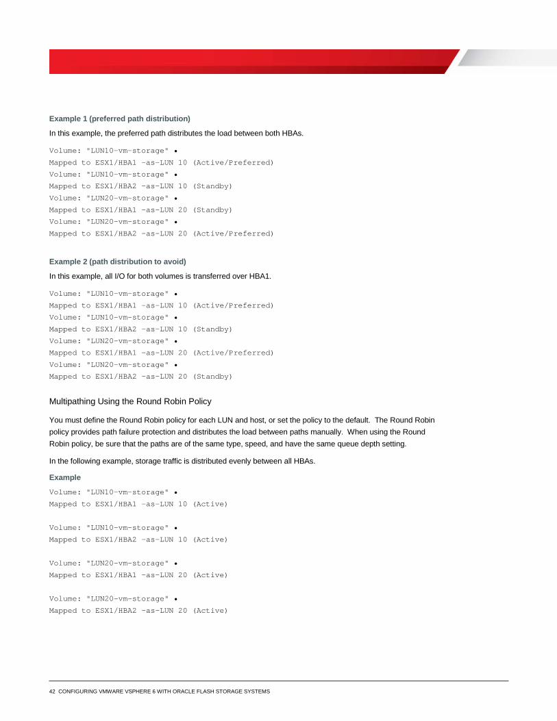
Example 1 (preferred path distribution)
In this example, the preferred path distributes the load between both HBAs.
Volume: "LUN10-vm-storage" •
Mapped to ESX1/HBA1 -as-LUN 10 (Active/Preferred)
Volume: "LUN10-vm-storage" •
Mapped to ESX1/HBA2 -as-LUN 10 (Standby)
Volume: "LUN20-vm-storage" •
Mapped to ESX1/HBA1 -as-LUN 20 (Standby)
Volume: "LUN20-vm-storage" •
Mapped to ESX1/HBA2 -as-LUN 20 (Active/Preferred)
Example 2 (path distribution to avoid)
In this example, all I/O for both volumes is transferred over HBA1.
Volume: "LUN10-vm-storage" •
Mapped to ESX1/HBA1 -as-LUN 10 (Active/Preferred)
Volume: "LUN10-vm-storage" •
Mapped to ESX1/HBA2 -as-LUN 10 (Standby)
Volume: "LUN20-vm-storage" •
Mapped to ESX1/HBA1 -as-LUN 20 (Active/Preferred)
Volume: "LUN20-vm-storage" •
Mapped to ESX1/HBA2 -as-LUN 20 (Standby)
Multipathing Using the Round Robin Policy
You must define the Round Robin policy for each LUN and host, or set the policy to the default. The Round Robin policy provides path failure protection and distributes the load between paths manually. When using the Round Robin policy, be sure that the paths are of the same type, speed, and have the same queue depth setting.
In the following example, storage traffic is distributed evenly between all HBAs.
Example
Volume: "LUN10-vm-storage" •
Mapped to ESX1/HBA1 -as-LUN 10 (Active)
Volume: "LUN10-vm-storage" •
Mapped to ESX1/HBA2 -as-LUN 10 (Active)
Volume: "LUN20-vm-storage" •
Mapped to ESX1/HBA1 -as-LUN 20 (Active)
Volume: "LUN20-vm-storage" •
Mapped to ESX1/HBA2 -as-LUN 20 (Active)
43 CONFIGURING VMWARE VSPHERE 6 WITH ORACLE FLASH STORAGE SYSTEMS
Change the Path Selection Policy
Generally, you are not required to change the default multipathing settings your host uses for a specific storage device. However, to change the default multipath settings, you can use the Edit Multipathing Policies dialog box in the vSphere Web Client.
The following steps modify a path selection policy and specify the preferred path for the Fixed policy.
1. Browse to the host in the vSphere Web Client navigator.
2. Click the Manage tab, and click Settings.
3. Select Connectivity and Multipathing.
4. Select the item whose paths you want to change.
5. Under Multipathing Details, click Edit Multipathing.
6. Select a path policy.
7. For the fixed policy, specify the preferred path.
8. Click OK to save your settings and exit the dialog box.
Asymmetric Logical Unit Access
The Asymmetric Logical Unit Access (ALUA) protocol was designed for arrays that VMware classifies as asymmetrical storage systems.
For example, for the path to the Controller where the volume is active, ALUA sets the path state as active-optimized. For the path to the partner Controller, ALUA sets the path state to standby. During a Controller failover, the ALUA path state changes so that the partner Controller becomes the active-optimized path.
Note: For other protocols supported by the Oracle FS System, such as FC, iSCSI, and FCoE, the pathing architecture remains mostly unchanged. Consistent with the former architecture, all the volume paths to the Controller on which that volume is active is labeled as active-optimized. Because the Oracle FS System does not proxy volume traffic between Controllers, the paths to the second Controller are set to the standby state, and the paths only change during a Controller failover.
For more detailed information about ALUA in a vSphere environment, see the VMware vSphere Blog post, “Configuration Settings for ALUA Devices”.
VMware Upgrades To guide you through the complicated process of planning VMware upgrades, use the Knowledge Base articles, release notes, and blogs listed in Appendix A. Related Documentation.
Before you begin any upgrades or fresh installations, read Update sequence for vSphere 6.0 and its compatible VMware products.
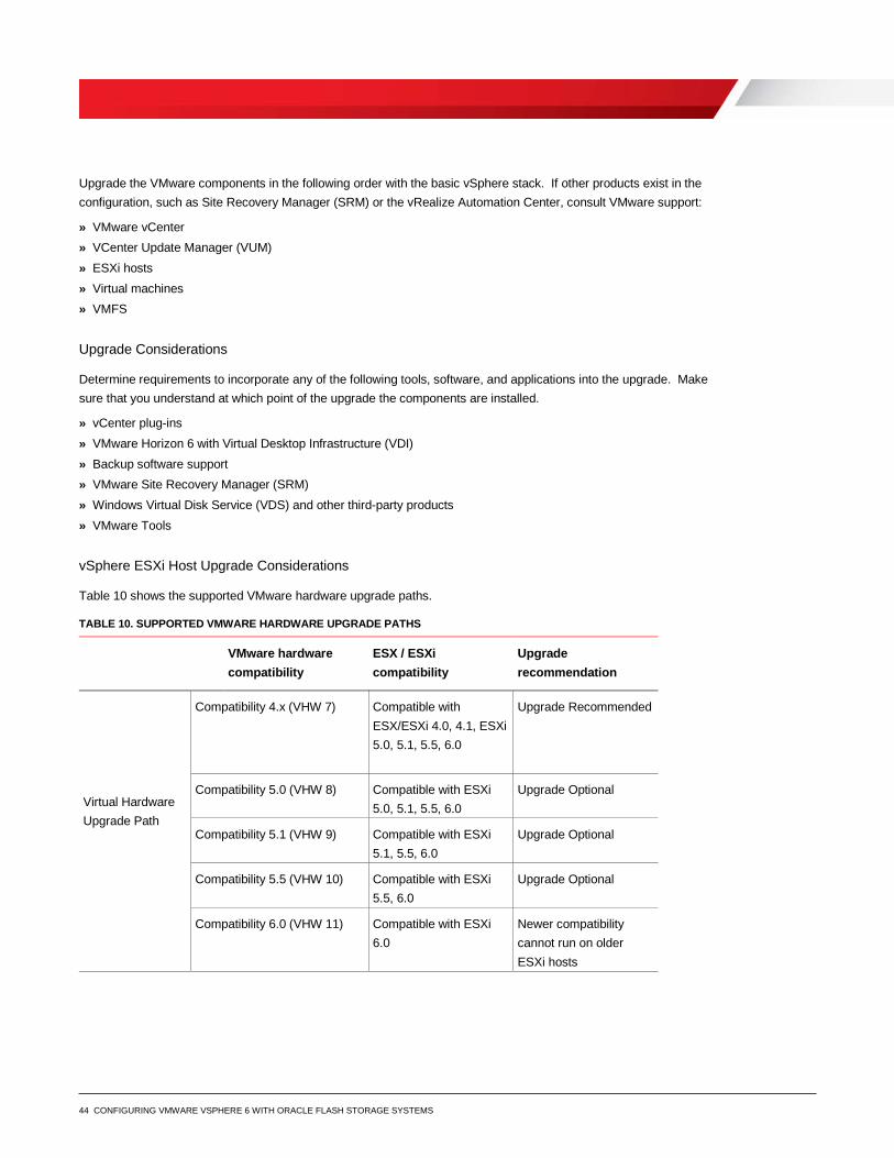
44 CONFIGURING VMWARE VSPHERE 6 WITH ORACLE FLASH STORAGE SYSTEMS
Upgrade the VMware components in the following order with the basic vSphere stack. If other products exist in the configuration, such as Site Recovery Manager (SRM) or the vRealize Automation Center, consult VMware support:
» VMware vCenter » VCenter Update Manager (VUM) » ESXi hosts » Virtual machines » VMFS
Upgrade Considerations
Determine requirements to incorporate any of the following tools, software, and applications into the upgrade. Make sure that you understand at which point of the upgrade the components are installed.
» vCenter plug-ins » VMware Horizon 6 with Virtual Desktop Infrastructure (VDI) » Backup software support » VMware Site Recovery Manager (SRM) » Windows Virtual Disk Service (VDS) and other third-party products » VMware Tools
vSphere ESXi Host Upgrade Considerations
Table 10 shows the supported VMware hardware upgrade paths.
TABLE 10. SUPPORTED VMWARE HARDWARE UPGRADE PATHS
VMware hardware compatibility
ESX / ESXi compatibility
Upgrade recommendation
Virtual Hardware Upgrade Path
Compatibility 4.x (VHW 7) Compatible with ESX/ESXi 4.0, 4.1, ESXi 5.0, 5.1, 5.5, 6.0
Upgrade Recommended
Compatibility 5.0 (VHW 8) Compatible with ESXi 5.0, 5.1, 5.5, 6.0
Upgrade Optional
Compatibility 5.1 (VHW 9) Compatible with ESXi 5.1, 5.5, 6.0
Upgrade Optional
Compatibility 5.5 (VHW 10) Compatible with ESXi 5.5, 6.0
Upgrade Optional
Compatibility 6.0 (VHW 11) Compatible with ESXi 6.0
Newer compatibility cannot run on older ESXi hosts
45 CONFIGURING VMWARE VSPHERE 6 WITH ORACLE FLASH STORAGE SYSTEMS
Consider the following before you upgrade an ESXi host:
» Consider whether to upgrade the host or perform a fresh installation. Whereas VMware recommends a fresh vCenter installation, VMware recommends upgrading ESXi hosts. By upgrading, you can use features such as HA, DRS, storage vMotion, and host profiles.
» To ensure host and firmware compatibility, check the VMware Compatibility Guide. » VSphere 6.x removed some drivers, such as RealTek NICs. A fresh install could result in missing NICs on your
server. » To understand known issues and workarounds, consult the VMware vSphere 6.0 Release Notes at
https://www.vmware.com/support/vsphere6/doc/vsphere-esxi-vcenter-server-60-release-notes.html. In addition, you can consult the following documents for a third-party perspective on VMware upgrades: Release Notes Part 1 Release Notes Part 2
» To view the vSphere Installation Bundle (VIBs) on your ESXi host, use the following command
esxcli software vib list
ESXi Host Upgrade Methods
The most popular and automated method for seamless upgrades is the vCenter Update Manager (VUM). VUM orchestrates host maintenance modes, respect DRS directives. Using VUM, you can upgrade directly from the ESXi 5.x host to the ESXi 6.0 host.
Other upgrade methods include the following:
» ESXi Installer – Boot from ISO and choose Upgrade. » vSphere Update Manager – Import the ISO image, create the upgrade baseline, and remediate the upgrade. » ESXCLI – Stage the ZIP file and run the system profile update command. » Scripted upgrades – Update and customize the upgrade script.
Upgrading Clusters
Note the following regarding Cluster upgrades:
» Rolling upgrades within clusters is supported and highly recommended. » vCenter 6.0 does not support ESX and ESXi 4.x hosts; therefore, upgrade them to 5.x before you upgrade the
vCenter. Before you upgrade, however, check for VM hardware compatibility. The ESXi host has wide latitude in virtual hardware support, so there is no critical rush to upgrade to hardware v10 or later.
» Use the HA, DRS, vMotion, and storage vMotion features. By using the features, there is minimal to zero downtime during the upgrade.
» If you are using Enterprise Plus, use the host profiles. Host profiles minimize configuration drift and enable stricter configuration control.
Upgrading ESXi Hosts
The boot disk is not repartitioned during the upgrade process but the contents are overwritten. The VMFS datastore on the boot volume or on scratch is preserved. Though a 1 GB LUN is the minimum size of space on the boot volume, Oracle recommends 5--6 GB LUNs for boot-from-SAN configurations.
46 CONFIGURING VMWARE VSPHERE 6 WITH ORACLE FLASH STORAGE SYSTEMS
For information on boot volume sizing, refer to Recommended disk sizes or LUN sizes for VMware ESX and ESXi versions.
Upgrading Virtual Machines
Previously, VMware called out the specific “hardware” version. With vSphere 6.x, VMware refers to the hardware as the “compatibility” level and associates the compatibility level to a release of the ESXi host. For example, if the virtual machine is HW v7, it displays as ESX 4.x and later in the vSphere Web Client.
Though updates are not required, valid reasons exist for upgrading. For example:
» A large virtual machine that is not supported on older versions of ESXi needs provisioning. » Performance with updated virtual machine hardware (vHW) versions needs improvement.
As a best practice, upgrade the vHW as part of your overall upgrade plan based on your specific requirements. Note the following regarding virtual machine upgrades:
» Upgrading VMware Tools and VM hardware is optional. » VMware Tools are largely backward-compatible and forward-compatible. » As a best practice, keep the VMware Tools up to date. If you detect problems with the backup software, HA, or
heartbeats, all of which rely on VMware Tools, verify the VMware Tools version matches your host. » Reboot the virtual machine when updating VMTools. » VMware hardware versions are not backwards compatible. Hardware version 11 virtual machines are only
compatible with vSphere 6.0.
Note: You cannot edit some of the new virtual machine features in the Windows C# client. You can, however, modify basic properties, such as RAM and vCPUs in the Windows C# client.
Upgrading VMFS
Understand the following when upgrading VMFS:
» The vSphere upgrade process » The differences between patches, updates, and upgrades » Different upgrade methods » VMware Tools » The best practice of using freshly format VMFS-5 volumes, as opposed to upgrading from VMFS-3 volumes. » Which certificate deployment model to use
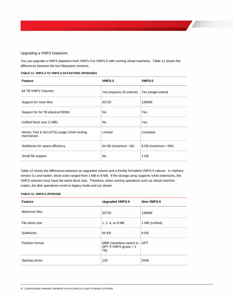
47 CONFIGURING VMWARE VSPHERE 6 WITH ORACLE FLASH STORAGE SYSTEMS
Upgrading a VMFS Datastore
You can upgrade a VMFS datastore from VMFS-3 to VMFS-5 with running virtual machines. Table 11 shows the differences between the two filesystem versions.
TABLE 11. VMFS-3 TO VMFS-5 DATASTORE UPGRADES
Feature VMFS-3 VMFS-5
64 TB VMFS Volumes Yes (requires 32 extents) Yes (single extent)
Support for more files 30720 130689
Support for 64 TB physical RDMs No Yes
Unified block size (1 MB) No Yes
Atomic Test & Set (ATS) usage (VAAI locking mechanism
Limited Complete
Subblocks for space efficiency 64 KB (maximum ~3k) 8 KB (maximum ~30k)
Small file support No 1 KB
Table 12 shows the differences between an upgraded volume and a freshly formatted VMFS-5 volume. In vSphere version 4.x and earlier, block sizes ranged from 1 MB to 8 MB. If the storage array supports VAAI extensions, the VMFS volumes must have the same block size. Therefore, when running operations such as virtual machine copies, the disk operations revert to legacy mode and run slower.
TABLE 12. VMFS-5 UPGRADE
Feature Upgraded VMFS-5 New VMFS-5
Maximum files 30720 130689
File block size 1, 2, 4, or 8 MB 1 MB (Unified)
Subblocks 64 KB 8 KB
Partition format MBR (seamless switch to GPT if VMFS grows > 2 TB)
GPT
Starting sector 128 2048
48 CONFIGURING VMWARE VSPHERE 6 WITH ORACLE FLASH STORAGE SYSTEMS
Recommendation for a VMFS Datastore Upgrade
VMware recommends that you first create a fresh VMFS datastore, and then storage vMotion your virtual machines into the datastore. After the datastore is evacuated, you can reformat or decommission it. Table 13 summarizes the recommendations for upgrading VMFS 3 and VMFS 5. A storage vMotion license is required to perform these actions.
TABLE 13. RECOMMENDATION FOR A VMFS DATASTORE UPGRADE
VMFS Version Upgrade recommendation
VMFS Upgrade Path
VMFS 3 Upgrade optional but not recommended
VMFS 5 VMFS 5 volumes cannot be mounted by 4.x hosts
Conclusion VMware vSphere offers customers several methods of providing storage to virtual machines. All of these storage methods provide customers with the flexibility in their infrastructure design, which in turn provides cost savings, increased storage use, and enhanced data recovery.
This white paper is not intended to be a definitive implementation guide or solution guide. Contact your Oracle representative if you need to solve specific deployments.
Related Documentation
In addition to the information contained in this document, refer to Oracle FS System documentation and VMware documentation listed in this section. VMware documentation includes information about the VMware vCenter, the ESXi host, the vSphere Web Client, and other related products.
Oracle Flash Storage Documentation
Oracle Flash Storage System Administrator's Guide
Oracle Flash Storage System CLI Commands
Oracle vSphere Plug-In User's Guide
Oracle Technical Support and Resources
• http://www.oracle.com/support (non-emergency business hours)
• Oracle global online support
49 CONFIGURING VMWARE VSPHERE 6 WITH ORACLE FLASH STORAGE SYSTEMS
VMware vSphere 6.x Documentation
VMware vSphere Troubleshooting
VMware vSphere Storage Guide
VMware vSphere Virtual Machine Administration Guide
VMware vSphere Monitoring and Performance Guide
VMware vSphere Availability Guide
VMware vSphere Data Protection
ESXi Host Configuration Documentation
For important information about configuring ESXi hosts to use the SAN, refer to the following URL:
https://www.vmware.com/support/pubs/vsphere-esxi-vcenter-server-6-pubs.html
Note: This document provides general recommendations that might not be applicable to all configurations.
VMware Upgrade Documentation
Table 14 provides important information related to upgrading vSphere, the vCenter, vCenter Update Manager (VUM), and the ESXi Host.
TABLE 14. VMWARE UPGRADE DOCUMENTATION
Document Document Location
Important Information before upgrading to vSphere 6.0 http://kb.vmware.com/kb/2110293
Upgrading to vCenter Server 6.0 best practices http://kb.vmware.com/kb/2109772
Update sequence for vSphere 6.0 and its compatible VMware products http://kb.vmware.com/kb/2109760
Methods for upgrading to VMware ESXi 6.0 http://kb.vmware.com/kb/2109711
Additional VMware Resource
VMware Support
• Education and training
• Online documentation
• VMware communities
Oracle Corporation, World Headquarters Worldwide Inquiries 500 Oracle Parkway Phone: +1.650.506.7000 Redwood Shores, CA 94065, USA Fax: +1.650.506.7200
C O N N E C T W I T H U S
blogs.oracle.com/oracle
facebook.com/oracle
twitter.com/oracle
oracle.com
Copyright © 2016, Oracle and/or its affiliates. All rights reserved. This document is provided for information purposes only, and the contents hereof are subject to change without notice. This document is not warranted to be error-free, nor subject to any other warranties or conditions, whether expressed orally or implied in law, including implied warranties and conditions of merchantability or fitness for a particular purpose. We specifically disclaim any liability with respect to this document, and no contractual obligations are formed either directly or indirectly by this document. This document may not be reproduced or transmitted in any form or by any means, electronic or mechanical, for any purpose, without our prior written permission. Oracle and Java are registered trademarks of Oracle and/or its affiliates. Other names may be trademarks of their respective owners. Intel and Intel Xeon are trademarks or registered trademarks of Intel Corporation. All SPARC trademarks are used under license and are trademarks or registered trademarks of SPARC International, Inc. AMD, Opteron, the AMD logo, and the AMD Opteron logo are trademarks or registered trademarks of Advanced Micro Devices. UNIX is a registered trademark of The Open Group. 0116 Configuring VMware vSphere 6 with Oracle Flash Storage Systems April 2016


![VMware vSphere 6 Software Description vSphere 6...[PRIMEQUEST(VMware) ]VMware vSphere 6.0 Documentation Center ・vSphere 6 Software Description(this document) vSphere Installation](https://static.fdocuments.us/doc/165x107/5a9f00a07f8b9a71178c28f6/pdfvmware-vsphere-6-software-description-vsphere-6primequestvmware-vmware.jpg)