
Configuring the 8-Port Channelized T1/E1 SPA · 15-2 Catalyst 6500 Series Switch SIP, SSC, and SPA...
24
CHAPTER 15-1 Catalyst 6500 Series Switch SIP, SSC, and SPA Software Configuration Guide OL-8655-04 15 Configuring the 8-Port Channelized T1/E1 SPA This chapter provides information about configuring the 8-Port Clear Channel T1/E1 SPA on the Catalyst 6500 Series switch. It includes the following sections: • Configuration Tasks, page 15-1 • Verifying the Interface Configuration, page 15-19 • Configuration Examples, page 15-20 For information about managing your system images and configuration files, refer to the Cisco IOS Configuration Fundamentals Configuration Guide, Release 12.2 and Cisco IOS Configuration Fundamentals Command Reference, Release 12.2 publications. For more information about the commands used in this chapter, see the Catalyst 6500 Series Cisco IOS Command Reference, 12.2SX publication. Also refer to the related Cisco IOS Release 12.2 software command reference and master index publications. For more information about accessing these publications, see the “Related Documentation” section on page xliv. Configuration Tasks This section describes how to configure the 8-Port Clear Channel T1/E1 SPA for the Catalyst 6500 Series switch and includes information about verifying the configuration. It includes the following topics: • Required Configuration Tasks, page 15-1 • Specifying the Interface Address on a SPA, page 15-6 • Optional Configurations, page 15-6 • Configuring QoS Features on Serial SPAs, page 15-19 Required Configuration Tasks This section lists the required configuration steps to configure the 8-Port Clear Channel T1/E1 SPA. Some of the required configuration commands implement default values that might be appropriate for your network. If the default value is correct for your network, then you do not need to configure the command. • Setting the Card Type, page 15-2 • Enabling the Interfaces on the Controller, page 15-3
Transcript of Configuring the 8-Port Channelized T1/E1 SPA · 15-2 Catalyst 6500 Series Switch SIP, SSC, and SPA...
Catalyst 6500 Series SwitcOL-8655-04
C H A P T E R 15
Configuring the 8-Port Channelized T1/E1 SPAThis chapter provides information about configuring the 8-Port Clear Channel T1/E1 SPA on the Catalyst 6500 Series switch. It includes the following sections:
• Configuration Tasks, page 15-1
• Verifying the Interface Configuration, page 15-19
• Configuration Examples, page 15-20
For information about managing your system images and configuration files, refer to the Cisco IOS Configuration Fundamentals Configuration Guide, Release 12.2 and Cisco IOS Configuration Fundamentals Command Reference, Release 12.2 publications.
For more information about the commands used in this chapter, see the Catalyst 6500 Series Cisco IOS Command Reference, 12.2SX publication. Also refer to the related Cisco IOS Release 12.2 software command reference and master index publications. For more information about accessing these publications, see the “Related Documentation” section on page xliv.
Configuration TasksThis section describes how to configure the 8-Port Clear Channel T1/E1 SPA for the Catalyst 6500 Series switch and includes information about verifying the configuration.
It includes the following topics:
• Required Configuration Tasks, page 15-1
• Specifying the Interface Address on a SPA, page 15-6
• Optional Configurations, page 15-6
• Configuring QoS Features on Serial SPAs, page 15-19
Required Configuration TasksThis section lists the required configuration steps to configure the 8-Port Clear Channel T1/E1 SPA. Some of the required configuration commands implement default values that might be appropriate for your network. If the default value is correct for your network, then you do not need to configure the command.
• Setting the Card Type, page 15-2
• Enabling the Interfaces on the Controller, page 15-3
15-1h SIP, SSC, and SPA Software Configuration Guide
Chapter 15 Configuring the 8-Port Channelized T1/E1 SPA Configuration Tasks
• Verifying Controller Configuration, page 15-4
• Setting the IP Address, page 15-5
• Verifying Interface Configuration, page 15-5
Note To better understand the address format used to specify the physical location of the SIP, SPA, and interfaces, see the “Specifying the Interface Address on a SPA” section on page 15-6.
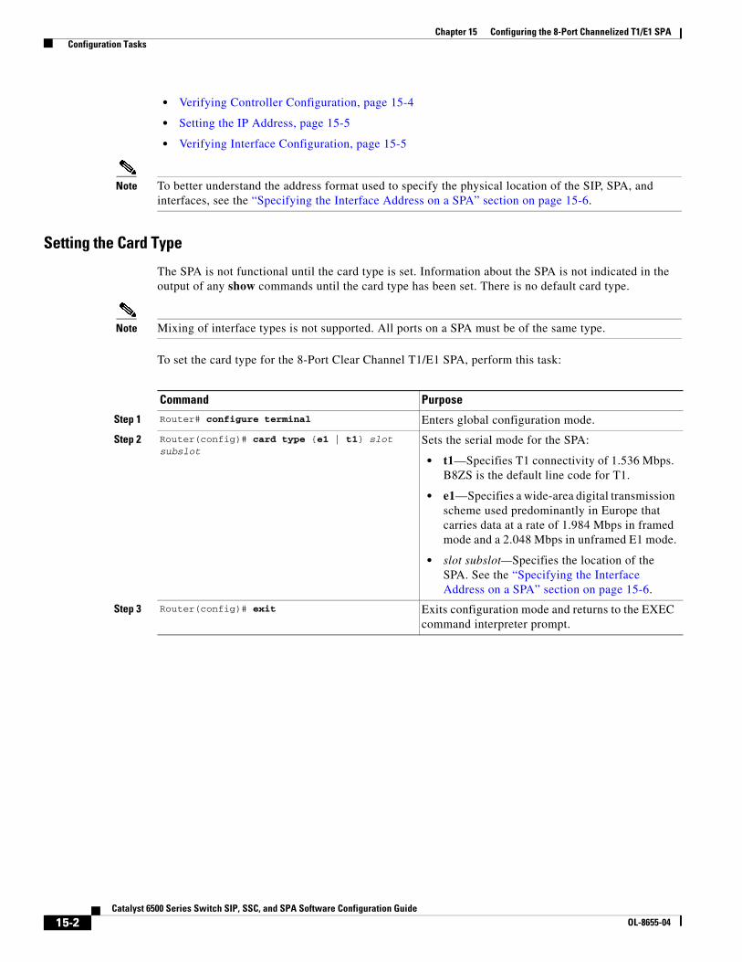
Setting the Card Type
The SPA is not functional until the card type is set. Information about the SPA is not indicated in the output of any show commands until the card type has been set. There is no default card type.
Note Mixing of interface types is not supported. All ports on a SPA must be of the same type.
To set the card type for the 8-Port Clear Channel T1/E1 SPA, perform this task:
Command Purpose
Step 1 Router# configure terminal Enters global configuration mode.
Step 2 Router(config)# card type {e1 | t1} slot subslot
Sets the serial mode for the SPA:
• t1—Specifies T1 connectivity of 1.536 Mbps. B8ZS is the default line code for T1.
• e1—Specifies a wide-area digital transmission scheme used predominantly in Europe that carries data at a rate of 1.984 Mbps in framed mode and a 2.048 Mbps in unframed E1 mode.
• slot subslot—Specifies the location of the SPA. See the “Specifying the Interface Address on a SPA” section on page 15-6.
Step 3 Router(config)# exit Exits configuration mode and returns to the EXEC command interpreter prompt.
15-2Catalyst 6500 Series Switch SIP, SSC, and SPA Software Configuration Guide
OL-8655-04
Chapter 15 Configuring the 8-Port Channelized T1/E1 SPA Configuration Tasks
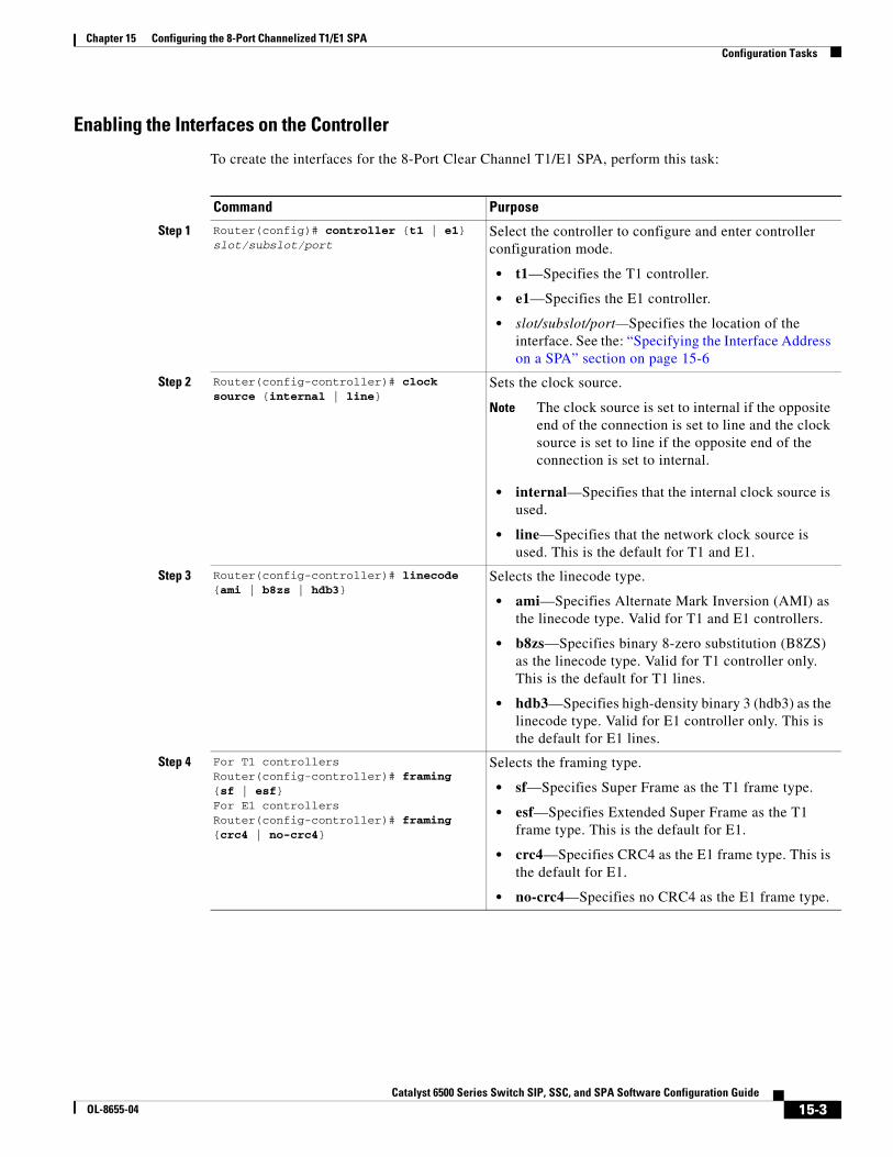
Enabling the Interfaces on the Controller
To create the interfaces for the 8-Port Clear Channel T1/E1 SPA, perform this task:
Command Purpose
Step 1 Router(config)# controller {t1 | e1} slot/subslot/port
Select the controller to configure and enter controller configuration mode.
• t1—Specifies the T1 controller.
• e1—Specifies the E1 controller.
• slot/subslot/port—Specifies the location of the interface. See the: “Specifying the Interface Address on a SPA” section on page 15-6
Step 2 Router(config-controller)# clock source {internal | line}
Sets the clock source.
Note The clock source is set to internal if the opposite end of the connection is set to line and the clock source is set to line if the opposite end of the connection is set to internal.
• internal—Specifies that the internal clock source is used.
• line—Specifies that the network clock source is used. This is the default for T1 and E1.
Step 3 Router(config-controller)# linecode {ami | b8zs | hdb3}
Selects the linecode type.
• ami—Specifies Alternate Mark Inversion (AMI) as the linecode type. Valid for T1 and E1 controllers.
• b8zs—Specifies binary 8-zero substitution (B8ZS) as the linecode type. Valid for T1 controller only. This is the default for T1 lines.
• hdb3—Specifies high-density binary 3 (hdb3) as the linecode type. Valid for E1 controller only. This is the default for E1 lines.
Step 4 For T1 controllersRouter(config-controller)# framing {sf | esf}For E1 controllersRouter(config-controller)# framing {crc4 | no-crc4}
Selects the framing type.
• sf—Specifies Super Frame as the T1 frame type.
• esf—Specifies Extended Super Frame as the T1 frame type. This is the default for E1.
• crc4—Specifies CRC4 as the E1 frame type. This is the default for E1.
• no-crc4—Specifies no CRC4 as the E1 frame type.
15-3Catalyst 6500 Series Switch SIP, SSC, and SPA Software Configuration Guide
OL-8655-04
Chapter 15 Configuring the 8-Port Channelized T1/E1 SPA Configuration Tasks
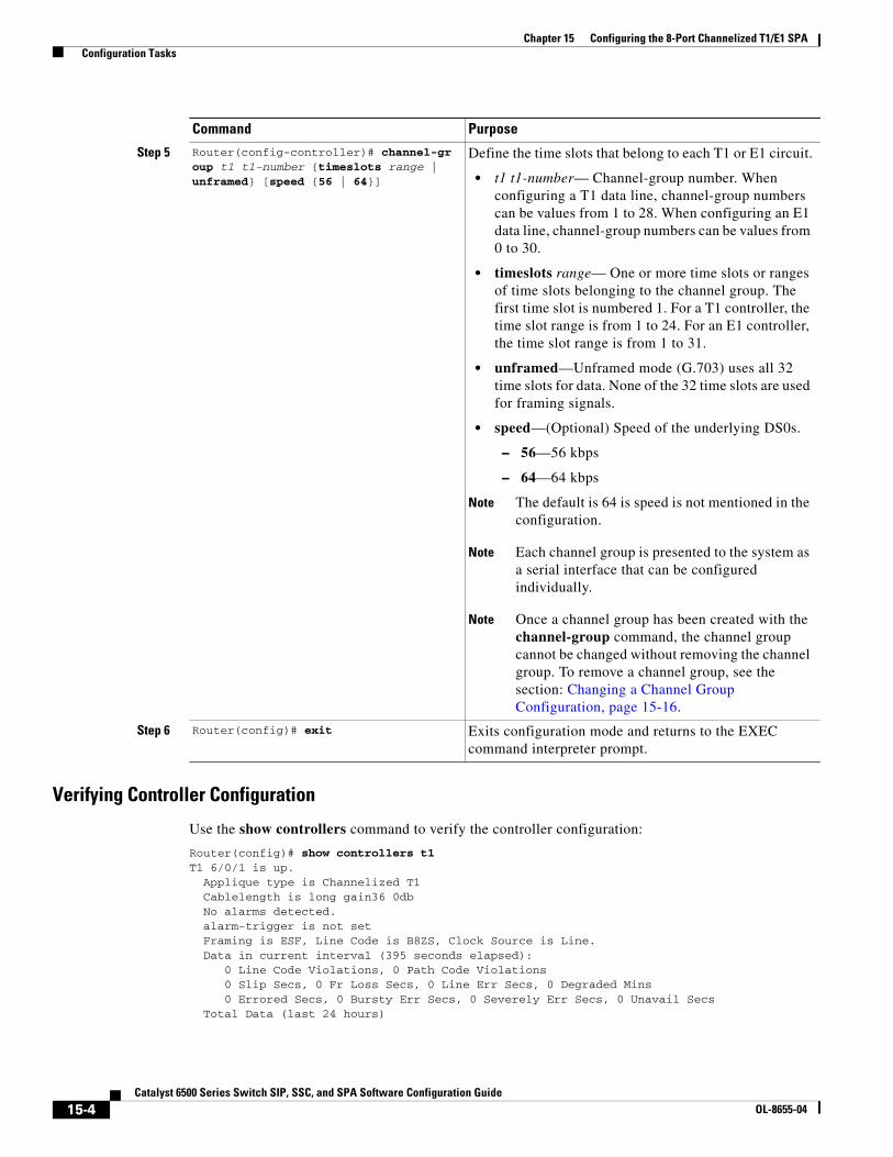
Verifying Controller Configuration
Use the show controllers command to verify the controller configuration:
Router(config)# show controllers t1T1 6/0/1 is up. Applique type is Channelized T1 Cablelength is long gain36 0db No alarms detected. alarm-trigger is not set Framing is ESF, Line Code is B8ZS, Clock Source is Line. Data in current interval (395 seconds elapsed): 0 Line Code Violations, 0 Path Code Violations 0 Slip Secs, 0 Fr Loss Secs, 0 Line Err Secs, 0 Degraded Mins 0 Errored Secs, 0 Bursty Err Secs, 0 Severely Err Secs, 0 Unavail Secs Total Data (last 24 hours)
Step 5 Router(config-controller)# channel-group t1 t1-number {timeslots range | unframed} [speed {56 | 64}]
Define the time slots that belong to each T1 or E1 circuit.
• t1 t1-number— Channel-group number. When configuring a T1 data line, channel-group numbers can be values from 1 to 28. When configuring an E1 data line, channel-group numbers can be values from 0 to 30.
• timeslots range— One or more time slots or ranges of time slots belonging to the channel group. The first time slot is numbered 1. For a T1 controller, the time slot range is from 1 to 24. For an E1 controller, the time slot range is from 1 to 31.
• unframed—Unframed mode (G.703) uses all 32 time slots for data. None of the 32 time slots are used for framing signals.
• speed—(Optional) Speed of the underlying DS0s.
– 56—56 kbps
– 64—64 kbps
Note The default is 64 is speed is not mentioned in the configuration.
Note Each channel group is presented to the system as a serial interface that can be configured individually.
Note Once a channel group has been created with the channel-group command, the channel group cannot be changed without removing the channel group. To remove a channel group, see the section: Changing a Channel Group Configuration, page 15-16.
Step 6 Router(config)# exit Exits configuration mode and returns to the EXEC command interpreter prompt.
Command Purpose
15-4Catalyst 6500 Series Switch SIP, SSC, and SPA Software Configuration Guide
OL-8655-04
Chapter 15 Configuring the 8-Port Channelized T1/E1 SPA Configuration Tasks
0 Line Code Violations, 0 Path Code Violations, 0 Slip Secs, 0 Fr Loss Secs, 0 Line Err Secs, 0 Degraded Mins, 0 Errored Secs, 0 Bursty Err Secs, 0 Severely Err Secs, 0 Unavail Secs
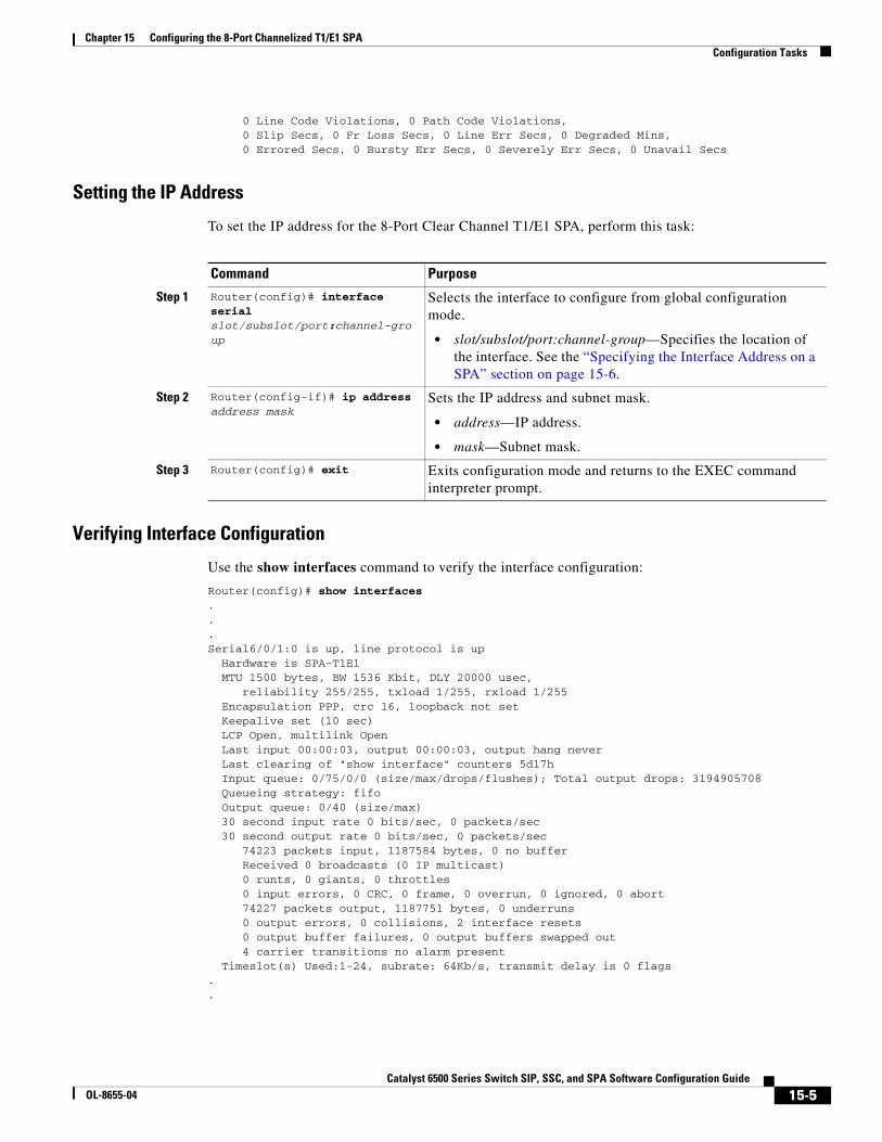
Setting the IP Address
To set the IP address for the 8-Port Clear Channel T1/E1 SPA, perform this task:
Verifying Interface Configuration
Use the show interfaces command to verify the interface configuration:
Router(config)# show interfaces...Serial6/0/1:0 is up, line protocol is up Hardware is SPA-T1E1 MTU 1500 bytes, BW 1536 Kbit, DLY 20000 usec, reliability 255/255, txload 1/255, rxload 1/255 Encapsulation PPP, crc 16, loopback not set Keepalive set (10 sec) LCP Open, multilink Open Last input 00:00:03, output 00:00:03, output hang never Last clearing of "show interface" counters 5d17h Input queue: 0/75/0/0 (size/max/drops/flushes); Total output drops: 3194905708 Queueing strategy: fifo Output queue: 0/40 (size/max) 30 second input rate 0 bits/sec, 0 packets/sec 30 second output rate 0 bits/sec, 0 packets/sec 74223 packets input, 1187584 bytes, 0 no buffer Received 0 broadcasts (0 IP multicast) 0 runts, 0 giants, 0 throttles 0 input errors, 0 CRC, 0 frame, 0 overrun, 0 ignored, 0 abort 74227 packets output, 1187751 bytes, 0 underruns 0 output errors, 0 collisions, 2 interface resets 0 output buffer failures, 0 output buffers swapped out 4 carrier transitions no alarm present Timeslot(s) Used:1-24, subrate: 64Kb/s, transmit delay is 0 flags..
Command Purpose
Step 1 Router(config)# interface serial slot/subslot/port:channel-group
Selects the interface to configure from global configuration mode.
• slot/subslot/port:channel-group—Specifies the location of the interface. See the “Specifying the Interface Address on a SPA” section on page 15-6.
Step 2 Router(config-if)# ip address address mask
Sets the IP address and subnet mask.
• address—IP address.
• mask—Subnet mask.
Step 3 Router(config)# exit Exits configuration mode and returns to the EXEC command interpreter prompt.
15-5Catalyst 6500 Series Switch SIP, SSC, and SPA Software Configuration Guide
OL-8655-04

Chapter 15 Configuring the 8-Port Channelized T1/E1 SPA Configuration Tasks
Specifying the Interface Address on a SPASPA interface ports begin numbering with “0” from left to right. Single-port SPAs use only the port number 0. To configure or monitor SPA interfaces, you need to specify the physical location of the SIP, SPA, and interface in the CLI. The interface address format is slot/subslot/port, where:
• slot—Specifies the chassis slot number in the Catalyst 6500 Series switch where the SIP is installed.
• subslot—Specifies the secondary slot of the SIP where the SPA is installed.
• port—Specifies the number of the individual interface port on a SPA.
The following example shows how to specify the first interface (0) on a SPA installed in the first subslot of a SIP (0) installed in chassis slot 3:
Router(config)# interface serial 3/0/0
This command shows a serial SPA as a representative example, however the same slot/subslot/port format is similarly used for other SPAs (such as ATM and POS) and other non-channelized SPAs.
For the 8-Port Channelized T1/E1 SPA, the interface address format is slot/subslot/port:channel-group, where:
• channel-group—Specifies the logical channel group assigned to the timeslots within the T1 link.
For more information about identifying slots and subslots, see the “Identifying Slots and Subslots for SIPs, SSCs, and SPAs” section on page 4-2.
Optional ConfigurationsThere are several standard, but optional, configurations that might be necessary to complete the configuration of your serial SPA.
Note For additional command output details, see the Catalyst 6500 Series Cisco IOS Command Reference, 12.2SX.
• Configuring Framing, page 15-7
• Configuring Encapsulation, page 15-8
• Configuring the CRC Size for T1, page 15-9
• Configuring FDL, page 15-10
• Configuring Multilink Point-to-Point Protocol (Hardware-based), page 15-11
• Configuring MLFR for T1/E1, page 15-13
• Invert Data on the T1/E1 Interface, page 15-15
• Changing a Channel Group Configuration, page 15-16
• Configuring Multipoint Bridging, page 15-16
• Configuring Bridging Control Protocol Support, page 15-16
• FRF.12 Guidelines, page 15-18
• LFI Guidelines, page 15-18
• Hardware MLPPP LFI Guidelines, page 15-18
• FRF.12 LFI Guidelines, page 15-19
15-6Catalyst 6500 Series Switch SIP, SSC, and SPA Software Configuration Guide
OL-8655-04

Chapter 15 Configuring the 8-Port Channelized T1/E1 SPA Configuration Tasks
• Configuring QoS Features on Serial SPAs, page 15-19
Configuring Framing
Framing is used to synchronize data transmission on the line. Framing allows the hardware to determine when each packet starts and ends. To configure framing, perform this task:
Verifying Framing Configuration
Use the show controllers command to verify the framing configuration:
Router# show controllers t1T1 6/0/0 is down. Applique type is Channelized T1 Cablelength is long gain36 0db Receiver has loss of frame. alarm-trigger is not set Framing is ESF, Line Code is B8ZS, Clock Source is Line. Data in current interval (717 seconds elapsed): 0 Line Code Violations, 0 Path Code Violations 0 Slip Secs, 0 Fr Loss Secs, 0 Line Err Secs, 0 Degraded Mins 0 Errored Secs, 0 Bursty Err Secs, 0 Severely Err Secs, 717 Unavail Secs Total Data (last 24 hours) 0 Line Code Violations, 0 Path Code Violations, 0 Slip Secs, 0 Fr Loss Secs, 0 Line Err Secs, 0 Degraded Mins, 0 Errored Secs, 0 Bursty Err Secs, 0 Severely Err Secs, 86400 Unavail Secs
Command Purpose
Step 1 Router# configure terminal Enters global configuration mode.
Step 2 Router(config)# controller {t1 | e1} slot/subslot/port
Selects the controller to configure.
• t1—Specifies the T1 controller.
• e1—Specifies the E1 controller.
• slot/subslot/port—Specifies the location of the controller. See “Specifying the Interface Address on a SPA” section on page 15-6.
Step 3 For T1 controllers:
Router(config-controller)#framing {sf | esf}
For E1 controllers:
Router(config-controller)#framing {crc4 | no-crc4 | unframed}
Set the framing on the interface.
• sf—Specifies Super Frame as the T1 frame type.
• esf—Specifies extended Super Frame as the T1 frame type. This is the default for T1.
• crc4—Specifies CRC4 frame as the E1 frame type. This is the default for E1.
• no-crc4—Specifies no CRC4 frame as the E1 frame type.
• unframed—Unframed mode (G.703) uses all 32 time slots for data.
15-7Catalyst 6500 Series Switch SIP, SSC, and SPA Software Configuration Guide
OL-8655-04
Chapter 15 Configuring the 8-Port Channelized T1/E1 SPA Configuration Tasks
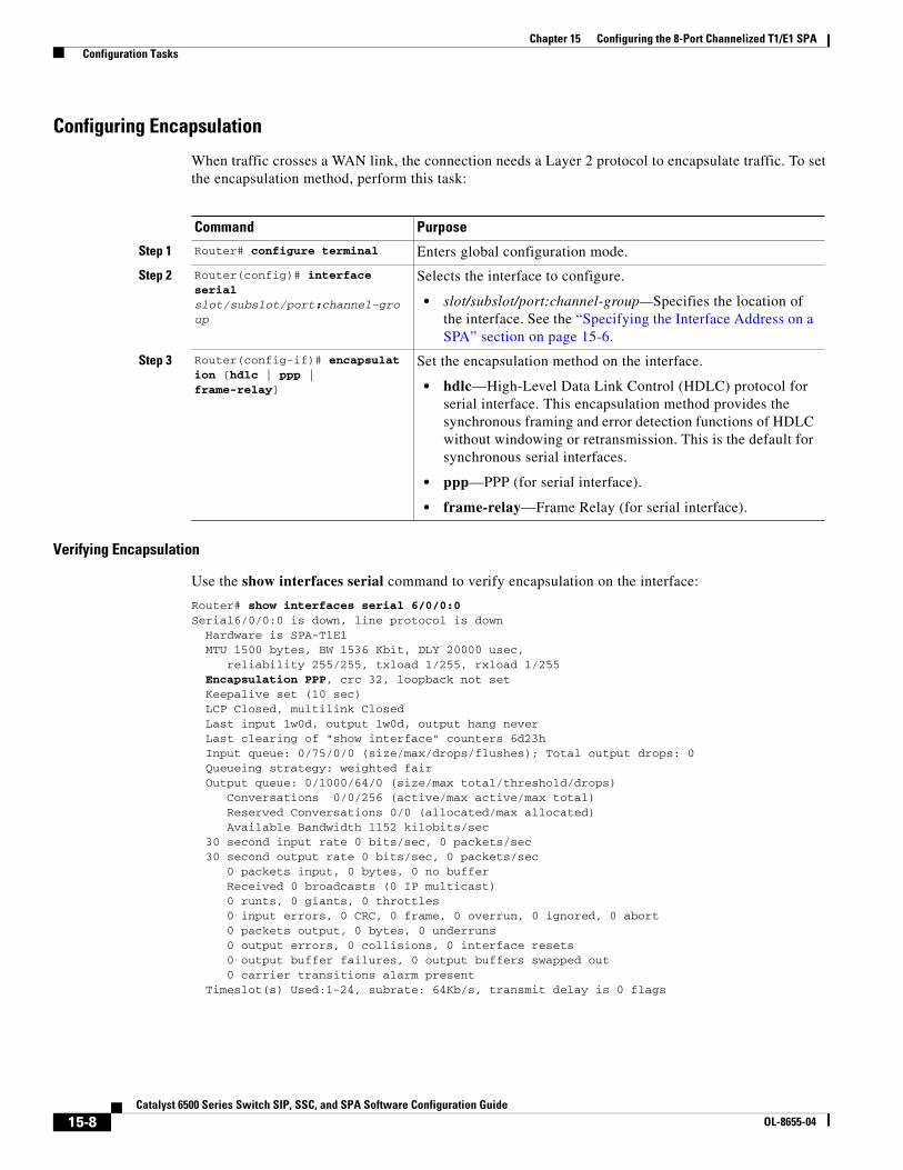
Configuring Encapsulation
When traffic crosses a WAN link, the connection needs a Layer 2 protocol to encapsulate traffic. To set the encapsulation method, perform this task:
Verifying Encapsulation
Use the show interfaces serial command to verify encapsulation on the interface:
Router# show interfaces serial 6/0/0:0Serial6/0/0:0 is down, line protocol is down Hardware is SPA-T1E1 MTU 1500 bytes, BW 1536 Kbit, DLY 20000 usec, reliability 255/255, txload 1/255, rxload 1/255 Encapsulation PPP, crc 32, loopback not set Keepalive set (10 sec) LCP Closed, multilink Closed Last input 1w0d, output 1w0d, output hang never Last clearing of "show interface" counters 6d23h Input queue: 0/75/0/0 (size/max/drops/flushes); Total output drops: 0 Queueing strategy: weighted fair Output queue: 0/1000/64/0 (size/max total/threshold/drops) Conversations 0/0/256 (active/max active/max total) Reserved Conversations 0/0 (allocated/max allocated) Available Bandwidth 1152 kilobits/sec 30 second input rate 0 bits/sec, 0 packets/sec 30 second output rate 0 bits/sec, 0 packets/sec 0 packets input, 0 bytes, 0 no buffer Received 0 broadcasts (0 IP multicast) 0 runts, 0 giants, 0 throttles 0 input errors, 0 CRC, 0 frame, 0 overrun, 0 ignored, 0 abort 0 packets output, 0 bytes, 0 underruns 0 output errors, 0 collisions, 0 interface resets 0 output buffer failures, 0 output buffers swapped out 0 carrier transitions alarm present Timeslot(s) Used:1-24, subrate: 64Kb/s, transmit delay is 0 flags
Command Purpose
Step 1 Router# configure terminal Enters global configuration mode.
Step 2 Router(config)# interface serial slot/subslot/port:channel-group
Selects the interface to configure.
• slot/subslot/port:channel-group—Specifies the location of the interface. See the “Specifying the Interface Address on a SPA” section on page 15-6.
Step 3 Router(config-if)# encapsulation {hdlc | ppp | frame-relay}
Set the encapsulation method on the interface.
• hdlc—High-Level Data Link Control (HDLC) protocol for serial interface. This encapsulation method provides the synchronous framing and error detection functions of HDLC without windowing or retransmission. This is the default for synchronous serial interfaces.
• ppp—PPP (for serial interface).
• frame-relay—Frame Relay (for serial interface).
15-8Catalyst 6500 Series Switch SIP, SSC, and SPA Software Configuration Guide
OL-8655-04

Chapter 15 Configuring the 8-Port Channelized T1/E1 SPA Configuration Tasks
Configuring the CRC Size for T1
All 8-Port Clear Channel T1/E1 SPA interfaces use a 16-bit cyclic redundancy check (CRC) by default, but also support a 32-bit CRC. CRC is an error-checking technique that uses a calculated numeric value to detect errors in transmitted data. The designators 16 and 32 indicate the length (in bits) of the frame check sequence (FCS). A CRC of 32 bits provides more powerful error detection, but adds overhead. Both the sender and receiver must use the same setting.
CRC-16, the most widely used CRC throughout the United States and Europe, is used extensively with WANs. CRC-32 is specified by IEEE 802 and as an option by some point-to-point transmission standards. It is often used on Switched Multimegabit Data Service (SMDS) networks and LANs.
To set the length of the CRC on a T1 interface, perform this task:
Verifying the CRC Size
Use the show interfaces serial command to verify the CRC size set on the interface:
Router# show interfaces serial 6/0/0:0Serial6/0/0:0 is up, line protocol is up Hardware is SPA-T1E1 MTU 1500 bytes, BW 1536 Kbit, DLY 20000 usec, reliability 255/255, txload 1/255, rxload 1/255 Encapsulation PPP, crc 32, loopback not set Keepalive set (10 sec) LCP Open, multilink Open Last input 00:00:38, output 00:00:00, output hang never Last clearing of "show interface" counters 01:46:16 Input queue: 0/75/0/0 (size/max/drops/flushes); Total output drops: 0 Queueing strategy: fifo Output queue: 0/40 (size/max) 30 second input rate 0 bits/sec, 0 packets/sec 30 second output rate 0 bits/sec, 0 packets/sec 1272 packets input, 20396 bytes, 0 no buffer Received 0 broadcasts (0 IP multicast) 0 runts, 0 giants, 0 throttles 6 input errors, 3 CRC, 0 frame, 0 overrun, 0 ignored, 3 abort 1276 packets output, 20460 bytes, 0 underruns 0 output errors, 0 collisions, 0 interface resets 0 output buffer failures, 0 output buffers swapped out 0 carrier transitions no alarm present Timeslot(s) Used:1-24, subrate: 64Kb/s, transmit delay is 0 flags
Command Purpose
Step 1 Router# configure terminal Enters global configuration mode.
Step 2 Router(config)# interface serial slot/subslot/port:channel-group
Selects the interface to configure.
• slot/subslot/port:channel-group—Specifies the location of the interface. See the “Specifying the Interface Address on a SPA” section on page 15-6.
Step 3 Router(config-if)# crc {16 | 32}
Selects the CRC size in bits.
• 16—16-bit CRC. This is the default
• 32—32-bit CRC.
15-9Catalyst 6500 Series Switch SIP, SSC, and SPA Software Configuration Guide
OL-8655-04

Chapter 15 Configuring the 8-Port Channelized T1/E1 SPA Configuration Tasks
Configuring FDL
Facility Data Link (FDL) is a 4-kbps channel provided by the Extended Super Frame (ESF) T1 framing format. The FDL performs outside the payload capacity and allows you to check error statistics on terminating equipment without intrusion.
Verifying FDL
Use the show controllers t1 command to verify the FDL setting:
Router# show controllers t1
T1 6/0/1 is up. Applique type is Channelized T1 Cablelength is long gain36 0db No alarms detected. alarm-trigger is not set Framing is ESF, FDL is ansi, Line Code is B8ZS, Clock Source is Line. Data in current interval (742 seconds elapsed): 0 Line Code Violations, 0 Path Code Violations 0 Slip Secs, 0 Fr Loss Secs, 0 Line Err Secs, 0 Degraded Mins 0 Errored Secs, 0 Bursty Err Secs, 0 Severely Err Secs, 0 Unavail Secs Total Data (last 73 15 minute intervals): 1278491 Line Code Violations, 3 Path Code Violations, 0 Slip Secs, 1 Fr Loss Secs, 177 Line Err Secs, 0 Degraded Mins, 3 Errored Secs, 0 Bursty Err Secs, 1 Severely Err Secs, 227 Unavail Secs...
Command Purpose
Step 1 Router# configure terminal Enters global configuration mode.
Step 2 Router(config)# controller t1 slot/subslot/port
Selects the controller to configure.
• slot/subslot/port—Specifies the location of the controller. See the “Specifying the Interface Address on a SPA” section on page 15-6.
Step 3 Router(config-controller)#fdl [ansi | att]
If the framing format was configured for esf, configures the format used for Facility Data Link (FDL).
• ansi—Use the ANSI T1.403 standard.
• att—Use the AT&T TR54016 standard.
15-10Catalyst 6500 Series Switch SIP, SSC, and SPA Software Configuration Guide
OL-8655-04
Chapter 15 Configuring the 8-Port Channelized T1/E1 SPA Configuration Tasks
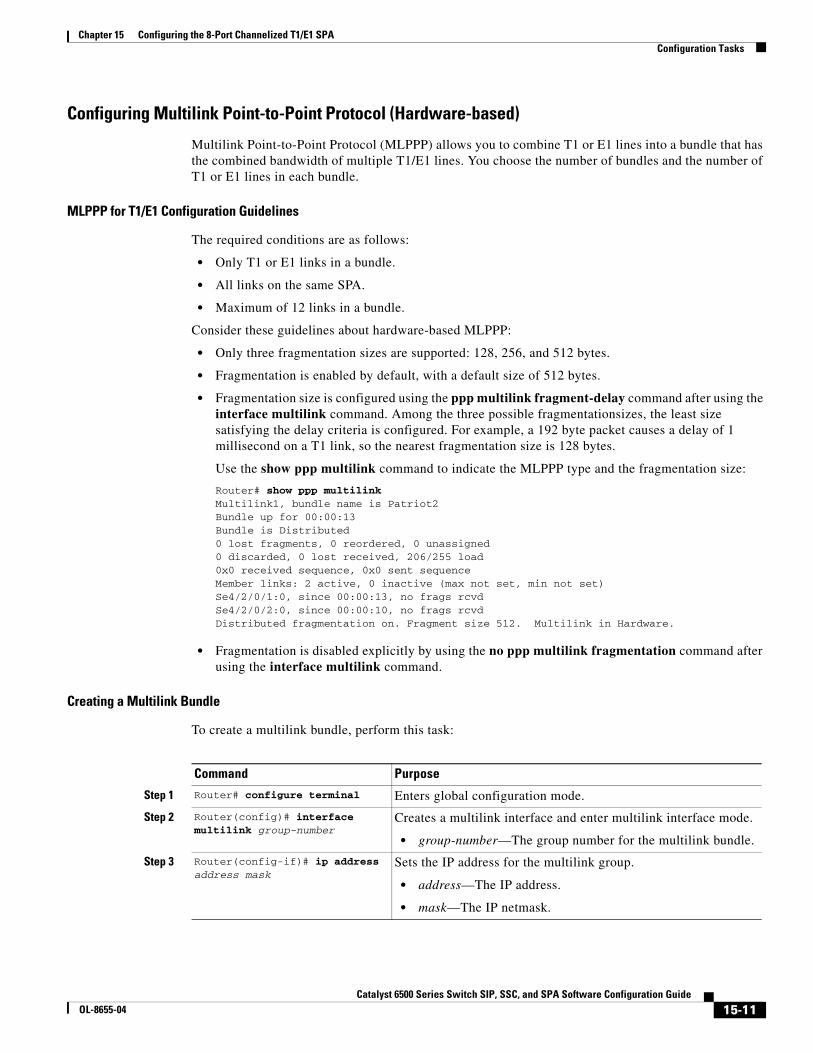
Configuring Multilink Point-to-Point Protocol (Hardware-based)
Multilink Point-to-Point Protocol (MLPPP) allows you to combine T1 or E1 lines into a bundle that has the combined bandwidth of multiple T1/E1 lines. You choose the number of bundles and the number of T1 or E1 lines in each bundle.
MLPPP for T1/E1 Configuration Guidelines
The required conditions are as follows:
• Only T1 or E1 links in a bundle.
• All links on the same SPA.
• Maximum of 12 links in a bundle.
Consider these guidelines about hardware-based MLPPP:
• Only three fragmentation sizes are supported: 128, 256, and 512 bytes.
• Fragmentation is enabled by default, with a default size of 512 bytes.
• Fragmentation size is configured using the ppp multilink fragment-delay command after using the interface multilink command. Among the three possible fragmentationsizes, the least size satisfying the delay criteria is configured. For example, a 192 byte packet causes a delay of 1 millisecond on a T1 link, so the nearest fragmentation size is 128 bytes.
Use the show ppp multilink command to indicate the MLPPP type and the fragmentation size:
Router# show ppp multilink Multilink1, bundle name is Patriot2Bundle up for 00:00:13Bundle is Distributed0 lost fragments, 0 reordered, 0 unassigned0 discarded, 0 lost received, 206/255 load0x0 received sequence, 0x0 sent sequence Member links: 2 active, 0 inactive (max not set, min not set)Se4/2/0/1:0, since 00:00:13, no frags rcvdSe4/2/0/2:0, since 00:00:10, no frags rcvdDistributed fragmentation on. Fragment size 512. Multilink in Hardware.
• Fragmentation is disabled explicitly by using the no ppp multilink fragmentation command after using the interface multilink command.
Creating a Multilink Bundle
To create a multilink bundle, perform this task:
Command Purpose
Step 1 Router# configure terminal Enters global configuration mode.
Step 2 Router(config)# interface multilink group-number
Creates a multilink interface and enter multilink interface mode.
• group-number—The group number for the multilink bundle.
Step 3 Router(config-if)# ip address address mask
Sets the IP address for the multilink group.
• address—The IP address.
• mask—The IP netmask.
15-11Catalyst 6500 Series Switch SIP, SSC, and SPA Software Configuration Guide
OL-8655-04

Chapter 15 Configuring the 8-Port Channelized T1/E1 SPA Configuration Tasks
Assigning an Interface to a Multilink Bundle
To assign an interface to a multilink bundle, perform this task:
Configuring Fragmentation Size on an MLPPP Bundle (optional)
To configure the fragmentation size on a multilink ppp bundle, perform this task:
Disabling the Fragmentation on an MLPPP Bundle (optional)
To assign an interface to a multilink bundle, perform this task:
Command Purpose
Step 1 Router# configure terminal Enters global configuration mode.
Step 2 Router(config)# interface serial slot/subslot/port/t1-number:channel-group
Selects the interface to configure and enters interface configuration mode. See the “Specifying the Interface Address on a SPA” section on page 15-6.
• slot/subslot/port/t1-number:channel-group—Select the interface to configure.
Step 3 Router(config-if)# encapsulation ppp
Enables PPP encapsulation.
Step 4 Router(config-if)# multilink-group group-number
Assigns the interface to a multilink bundle.
• group-number—The multilink group number for the T1 or E1 bundle.
Step 5 Router(config-if)# ppp multilink
Enables multilink PPP on the interface.
Repeat these commands for each interface you want to assign to the multilink bundle.
Command Purpose
Step 1 Router# configure terminal Enters global configuration mode.
Step 2 Router(config)# interface multilink slot/subslot/port/t1-number:channel-group
Creates a multilink interface and enters multilink interface mode.
• group-number—The group number for the multilink bundle. The range is 1 to 2147483647.
Step 3 Router(config-if)# ppp multilink fragment-delay delay
Sets the fragmentation size satisfying the configured delay on the multilink bundle.
• delay—Delay in milliseconds.
Command Purpose
Step 1 Router# configure terminal Enters global configuration mode.
Step 2 Router(config)# interface multilink group-number
Creates a multilink interface and enters multilink interface mode.
• group-number—The group number for the multilink bundle. The range is 1 to 2147483647.
Step 3 Router(config-if)# no ppp multilink fragmentation
Disables the fragmentation on the multilink bundle.
15-12Catalyst 6500 Series Switch SIP, SSC, and SPA Software Configuration Guide
OL-8655-04

Chapter 15 Configuring the 8-Port Channelized T1/E1 SPA Configuration Tasks
Verifying Multilink PPP
Use the show ppp multilink command to verify the PPP multilinks:
Router# show ppp multilinkMultilink1, bundle name is mybundle
Bundle up for 01:40:50Bundle is Distributed0 lost fragments, 0 reordered, 0 unassigned0 discarded, 0 lost received, 1/255 load0x0 received sequence, 0x0 sent sequence
Member links: 5 active, 0 inactive (max not set, min not set)Se6/0/0/1:0, since 01:40:50, no frags rcvdSe6/0/1/1:0, since 01:40:09, no frags rcvdSe6/0/3/1:0, since 01:15:44, no frags rcvdSe6/0/4/1:0, since 01:03:17, no frags rcvdSe6/0/6/1:0, since 01:01:06, no frags rcvdSe6/0/6:0, since 01:01:06, no frags rcvd
Configuring MLFR for T1/E1
Multilink Frame Relay (MLFR) allows you to combine T1/E1 lines into a bundle that has the combined bandwidth of multiple T1/E1 lines. You choose the number of bundles and the number of T1/E1 lines in each bundle. This feature allows you to increase the bandwidth of your network links beyond that of a single T1/E1 line.
MLFR for T1/E1 Configuration Guidelines
MLFR will function in hardware if all of the following conditions are met:
• Only T1 or E1 member links.
• All links are on the same SPA.
• Maximum of 12 links in a bundle.
Create a Multilink Bundle
To create a multilink bundle, perform this task:
Command Purpose
Step 1 Router# configure terminal Enters global configuration mode.
Step 2 Router(config)# interface mfr number
Configures a multilink Frame Relay bundle interface.
• number—The number for the Frame Relay bundle.
Step 3 Router(config-if)# frame-relay multilink bid name
(Optional) Assigns a bundle identification name to a multilink Frame Relay bundle.
• name—The name for the Frame Relay bundle.
Note The bundle identification (BID) will not go into effect until the interface has gone from the down state to the up state. One way to bring the interface down and back up again is by using the shut and no shut commands in interface configuration mode.
15-13Catalyst 6500 Series Switch SIP, SSC, and SPA Software Configuration Guide
OL-8655-04
Chapter 15 Configuring the 8-Port Channelized T1/E1 SPA Configuration Tasks
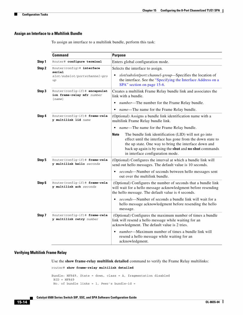
Assign an Interface to a Multilink Bundle
To assign an interface to a multilink bundle, perform this task:
Verifying Multilink Frame Relay
Use the show frame-relay multilink detailed command to verify the Frame Relay multilinks:
router# show frame-relay multilink detailed
Bundle: MFR49, State = down, class = A, fragmentation disabled BID = MFR49 No. of bundle links = 1, Peer's bundle-id =
Command Purpose
Step 1 Router# configure terminal Enters global configuration mode.
Step 2 Router(config)# interface serial slot/subslot/port:channel-group
Selects the interface to assign.
• slot/subslot/port:channel-group—Specifies the location of the interface. See the “Specifying the Interface Address on a SPA” section on page 15-6.
Step 3 Router(config-if)# encapsulation frame-relay mfr number [name]
Creates a multilink Frame Relay bundle link and associates the link with a bundle.
• number—The number for the Frame Relay bundle.
• name—The name for the Frame Relay bundle.
Step 4 Router(config-if)# frame-relay multilink lid name
(Optional) Assigns a bundle link identification name with a multilink Frame Relay bundle link.
• name—The name for the Frame Relay bundle.
Note The bundle link identification (LID) will not go into effect until the interface has gone from the down state to the up state. One way to bring the interface down and back up again is by using the shut and no shut commands in interface configuration mode.
Step 5 Router(config-if)# frame-relay multilink hello seconds
(Optional) Configures the interval at which a bundle link will send out hello messages. The default value is 10 seconds.
• seconds—Number of seconds between hello messages sent out over the multilink bundle.
Step 6 Router(config-if)# frame-relay multilink ack seconds
(Optional) Configures the number of seconds that a bundle link will wait for a hello message acknowledgment before resending the hello message. The default value is 4 seconds.
• seconds—Number of seconds a bundle link will wait for a hello message acknowledgment before resending the hello message.
Step 7 Router(config-if)# frame-relay multilink retry number
(Optional) Configures the maximum number of times a bundle link will resend a hello message while waiting for an acknowledgment. The default value is 2 tries.
• number—Maximum number of times a bundle link will resend a hello message while waiting for an acknowledgment.
15-14Catalyst 6500 Series Switch SIP, SSC, and SPA Software Configuration Guide
OL-8655-04

Chapter 15 Configuring the 8-Port Channelized T1/E1 SPA Configuration Tasks
Bundle links:
Serial6/0/0:0, HW state = up, link state = Add_sent, LID = test Cause code = none, Ack timer = 4, Hello timer = 10, Max retry count = 2, Current count = 0, Peer LID = , RTT = 0 ms Statistics: Add_link sent = 21, Add_link rcv'd = 0, Add_link ack sent = 0, Add_link ack rcv'd = 0, Add_link rej sent = 0, Add_link rej rcv'd = 0, Remove_link sent = 0, Remove_link rcv'd = 0, Remove_link_ack sent = 0, Remove_link_ack rcv'd = 0, Hello sent = 0, Hello rcv'd = 0, Hello_ack sent = 0, Hello_ack rcv'd = 0, outgoing pak dropped = 0, incoming pak dropped = 0
Invert Data on the T1/E1 Interface
If the interface on the 8-Port Clear Channel T1/E1 SPA is used to drive a dedicated T1 line that does not have B8ZS encoding, you must invert the data stream on the connecting CSU/DSU or on the interface. Be careful not to invert data on both the CSU/DSU and the interface, as two data inversions will cancel each other out. To invert data on a T1/E1 interface, perform this task:
Use the show running configuration command to verify that invert data has been set:
Router# show running configuration...interface Serial6/0/0:0 no ip address encapsulation ppp logging event link-status load-interval 30 invert data no cdp enable ppp chap hostname group1 ppp multilink multilink-group 1! ...
Command Purpose
Step 1 Router# configure terminal Enters global configuration mode.
Step 2 Router(config)# interface serial slot/subslot/port:channel-group
Selects the serial interface.
Step 3 Router(config-if)# invert data
Inverts the data stream.
15-15Catalyst 6500 Series Switch SIP, SSC, and SPA Software Configuration Guide
OL-8655-04
Chapter 15 Configuring the 8-Port Channelized T1/E1 SPA Configuration Tasks
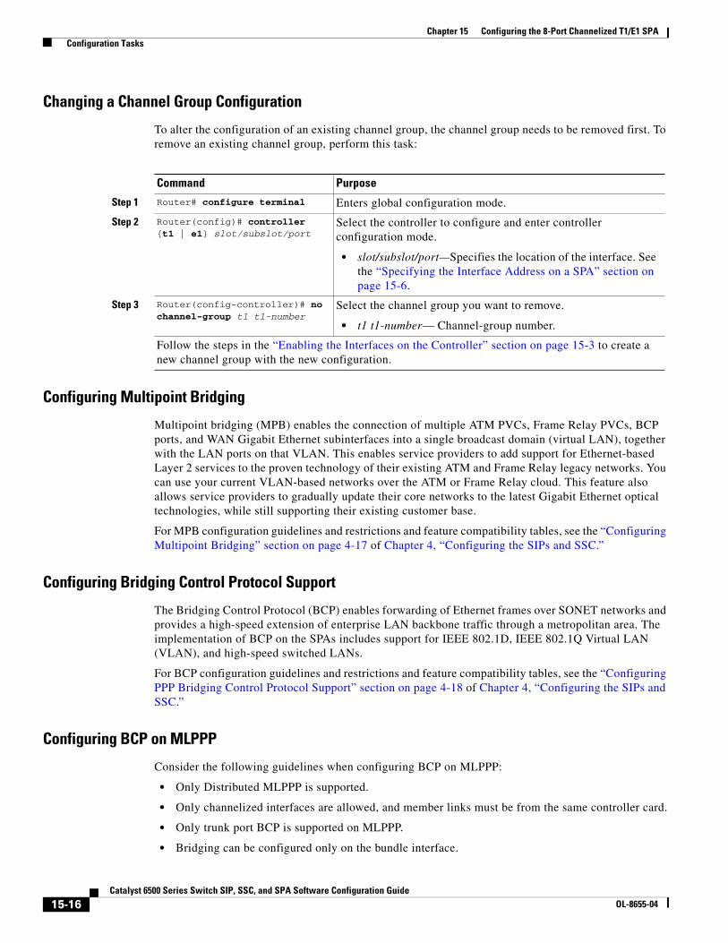
Changing a Channel Group Configuration
To alter the configuration of an existing channel group, the channel group needs to be removed first. To remove an existing channel group, perform this task:
Configuring Multipoint Bridging
Multipoint bridging (MPB) enables the connection of multiple ATM PVCs, Frame Relay PVCs, BCP ports, and WAN Gigabit Ethernet subinterfaces into a single broadcast domain (virtual LAN), together with the LAN ports on that VLAN. This enables service providers to add support for Ethernet-based Layer 2 services to the proven technology of their existing ATM and Frame Relay legacy networks. You can use your current VLAN-based networks over the ATM or Frame Relay cloud. This feature also allows service providers to gradually update their core networks to the latest Gigabit Ethernet optical technologies, while still supporting their existing customer base.
For MPB configuration guidelines and restrictions and feature compatibility tables, see the “Configuring Multipoint Bridging” section on page 4-17 of Chapter 4, “Configuring the SIPs and SSC.”
Configuring Bridging Control Protocol Support
The Bridging Control Protocol (BCP) enables forwarding of Ethernet frames over SONET networks and provides a high-speed extension of enterprise LAN backbone traffic through a metropolitan area. The implementation of BCP on the SPAs includes support for IEEE 802.1D, IEEE 802.1Q Virtual LAN (VLAN), and high-speed switched LANs.
For BCP configuration guidelines and restrictions and feature compatibility tables, see the “Configuring PPP Bridging Control Protocol Support” section on page 4-18 of Chapter 4, “Configuring the SIPs and SSC.”
Configuring BCP on MLPPP
Consider the following guidelines when configuring BCP on MLPPP:
• Only Distributed MLPPP is supported.
• Only channelized interfaces are allowed, and member links must be from the same controller card.
• Only trunk port BCP is supported on MLPPP.
• Bridging can be configured only on the bundle interface.
Command Purpose
Step 1 Router# configure terminal Enters global configuration mode.
Step 2 Router(config)# controller {t1 | e1} slot/subslot/port
Select the controller to configure and enter controller configuration mode.
• slot/subslot/port—Specifies the location of the interface. See the “Specifying the Interface Address on a SPA” section on page 15-6.
Step 3 Router(config-controller)# no channel-group t1 t1-number
Select the channel group you want to remove.
• t1 t1-number— Channel-group number.
Follow the steps in the “Enabling the Interfaces on the Controller” section on page 15-3 to create a new channel group with the new configuration.
15-16Catalyst 6500 Series Switch SIP, SSC, and SPA Software Configuration Guide
OL-8655-04
Chapter 15 Configuring the 8-Port Channelized T1/E1 SPA Configuration Tasks
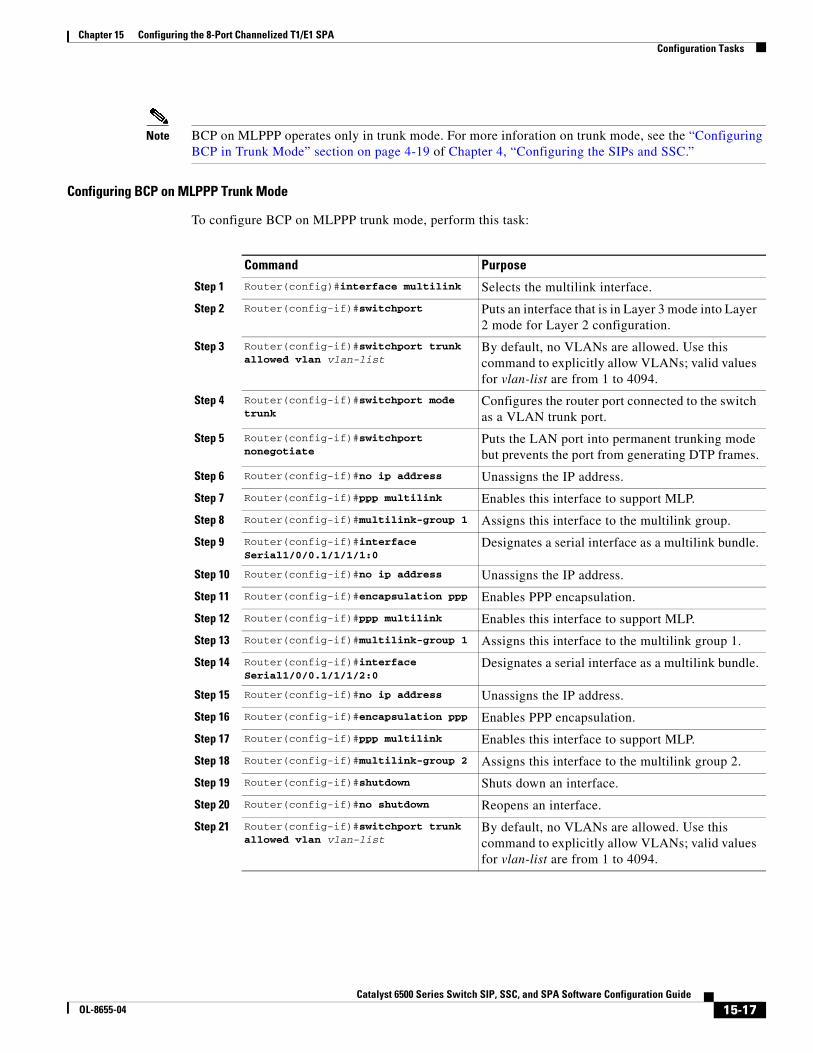
Note BCP on MLPPP operates only in trunk mode. For more inforation on trunk mode, see the “Configuring BCP in Trunk Mode” section on page 4-19 of Chapter 4, “Configuring the SIPs and SSC.”
Configuring BCP on MLPPP Trunk Mode
To configure BCP on MLPPP trunk mode, perform this task:
Command Purpose
Step 1 Router(config)#interface multilink Selects the multilink interface.
Step 2 Router(config-if)#switchport Puts an interface that is in Layer 3 mode into Layer 2 mode for Layer 2 configuration.
Step 3 Router(config-if)#switchport trunk allowed vlan vlan-list
By default, no VLANs are allowed. Use this command to explicitly allow VLANs; valid values for vlan-list are from 1 to 4094.
Step 4 Router(config-if)#switchport mode trunk
Configures the router port connected to the switch as a VLAN trunk port.
Step 5 Router(config-if)#switchport nonegotiate
Puts the LAN port into permanent trunking mode but prevents the port from generating DTP frames.
Step 6 Router(config-if)#no ip address Unassigns the IP address.
Step 7 Router(config-if)#ppp multilink Enables this interface to support MLP.
Step 8 Router(config-if)#multilink-group 1 Assigns this interface to the multilink group.
Step 9 Router(config-if)#interface Serial1/0/0.1/1/1/1:0
Designates a serial interface as a multilink bundle.
Step 10 Router(config-if)#no ip address Unassigns the IP address.
Step 11 Router(config-if)#encapsulation ppp Enables PPP encapsulation.
Step 12 Router(config-if)#ppp multilink Enables this interface to support MLP.
Step 13 Router(config-if)#multilink-group 1 Assigns this interface to the multilink group 1.
Step 14 Router(config-if)#interface Serial1/0/0.1/1/1/2:0
Designates a serial interface as a multilink bundle.
Step 15 Router(config-if)#no ip address Unassigns the IP address.
Step 16 Router(config-if)#encapsulation ppp Enables PPP encapsulation.
Step 17 Router(config-if)#ppp multilink Enables this interface to support MLP.
Step 18 Router(config-if)#multilink-group 2 Assigns this interface to the multilink group 2.
Step 19 Router(config-if)#shutdown Shuts down an interface.
Step 20 Router(config-if)#no shutdown Reopens an interface.
Step 21 Router(config-if)#switchport trunk allowed vlan vlan-list
By default, no VLANs are allowed. Use this command to explicitly allow VLANs; valid values for vlan-list are from 1 to 4094.
15-17Catalyst 6500 Series Switch SIP, SSC, and SPA Software Configuration Guide
OL-8655-04

Chapter 15 Configuring the 8-Port Channelized T1/E1 SPA Configuration Tasks
Verifying BCP on MLPPP Trunk Mode
To display information about Multilink PPP, perform this task in EXEC mode.
The following shows an example of show ppp multilink:
Router# show ppp multilink
Multilink1, bundle name is group 1Bundle is Distributed0 lost fragments, 0 reordered, 0 unassigned, sequence 0x0/0x0 rcvd/sent0 discarded, 0 lost received, 1/255 loadMember links: 4 active, 0 inactive (max no set, min not set)Serial1/0/0/:1Serial1/0/0/:2Serial1/0/0/:3Serial1/0/0/:4
FRF.12 Guidelines
FRF.12 functions in hardware. Note the following guidelines:
• The fragmentation is configured at the main interface.
• Only three fragmentation sizes are supported: 128, 256, and 512 bytes.
LFI Guidelines
LFI can function by using either FRF.12 or MLPPP. MLPPP LFI operates in both hardware and software while FRF.12 LFI operates only in hardware.
Hardware MLPPP LFI Guidelines
LFI using MLPPP will function only in hardware if there is just one member link in the MLPPP bundle. The link can be a fractional T1 or full T1. Note the following guidelines:
• The ppp multilink interleave command must be configured to enable interleaving.
• Only three fragmentation sizes are supported: 128 bytes, 256 bytes, and 512 bytes.
• Fragmentation is enabled by default, and the default size is 512 bytes.
• A policy map having a priority class must be applied to the main interface.
• When hardware-based LFI is enabled, fragmentation counters are not displayed.
Command Purpose
Router(config-if)# show ppp multilink Displays information on a multilink group.
15-18Catalyst 6500 Series Switch SIP, SSC, and SPA Software Configuration Guide
OL-8655-04
Chapter 15 Configuring the 8-Port Channelized T1/E1 SPA Verifying the Interface Configuration
FRF.12 LFI Guidelines
LFI using FRF.12 is always performed in hardware. Note the following guidelines:
• The fragmentation is configured at the main interface.
• Only three fragmentation sizes are supported: 128 bytes, 256 bytes, and 512 bytes.
• A policy map having a priority class must be applied to the main interface.
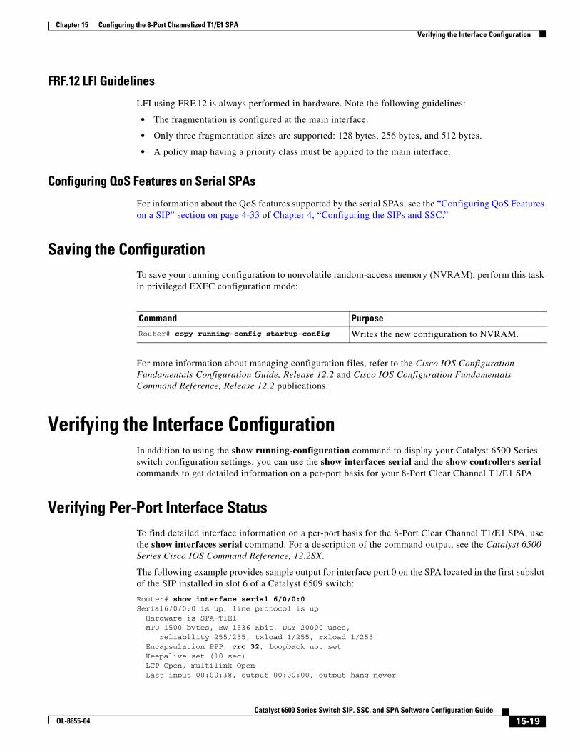
Configuring QoS Features on Serial SPAs
For information about the QoS features supported by the serial SPAs, see the “Configuring QoS Features on a SIP” section on page 4-33 of Chapter 4, “Configuring the SIPs and SSC.”
Saving the ConfigurationTo save your running configuration to nonvolatile random-access memory (NVRAM), perform this task in privileged EXEC configuration mode:
For more information about managing configuration files, refer to the Cisco IOS Configuration Fundamentals Configuration Guide, Release 12.2 and Cisco IOS Configuration Fundamentals Command Reference, Release 12.2 publications.
Verifying the Interface ConfigurationIn addition to using the show running-configuration command to display your Catalyst 6500 Series switch configuration settings, you can use the show interfaces serial and the show controllers serial commands to get detailed information on a per-port basis for your 8-Port Clear Channel T1/E1 SPA.
Verifying Per-Port Interface StatusTo find detailed interface information on a per-port basis for the 8-Port Clear Channel T1/E1 SPA, use the show interfaces serial command. For a description of the command output, see the Catalyst 6500 Series Cisco IOS Command Reference, 12.2SX.
The following example provides sample output for interface port 0 on the SPA located in the first subslot of the SIP installed in slot 6 of a Catalyst 6509 switch:
Router# show interface serial 6/0/0:0Serial6/0/0:0 is up, line protocol is up Hardware is SPA-T1E1 MTU 1500 bytes, BW 1536 Kbit, DLY 20000 usec, reliability 255/255, txload 1/255, rxload 1/255 Encapsulation PPP, crc 32, loopback not set Keepalive set (10 sec) LCP Open, multilink Open Last input 00:00:38, output 00:00:00, output hang never
Command Purpose
Router# copy running-config startup-config Writes the new configuration to NVRAM.
15-19Catalyst 6500 Series Switch SIP, SSC, and SPA Software Configuration Guide
OL-8655-04
Chapter 15 Configuring the 8-Port Channelized T1/E1 SPA Configuration Examples
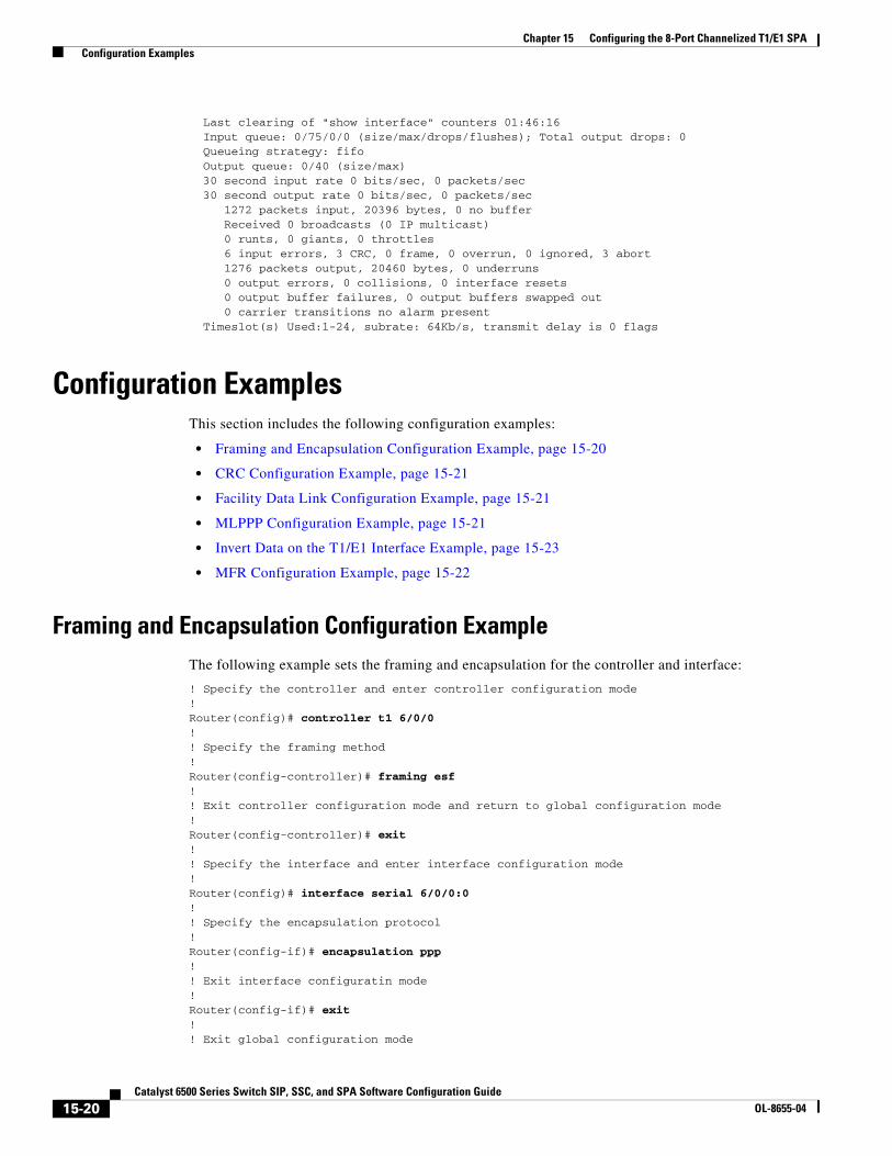
Last clearing of "show interface" counters 01:46:16 Input queue: 0/75/0/0 (size/max/drops/flushes); Total output drops: 0 Queueing strategy: fifo Output queue: 0/40 (size/max) 30 second input rate 0 bits/sec, 0 packets/sec 30 second output rate 0 bits/sec, 0 packets/sec 1272 packets input, 20396 bytes, 0 no buffer Received 0 broadcasts (0 IP multicast) 0 runts, 0 giants, 0 throttles 6 input errors, 3 CRC, 0 frame, 0 overrun, 0 ignored, 3 abort 1276 packets output, 20460 bytes, 0 underruns 0 output errors, 0 collisions, 0 interface resets 0 output buffer failures, 0 output buffers swapped out 0 carrier transitions no alarm present Timeslot(s) Used:1-24, subrate: 64Kb/s, transmit delay is 0 flags
Configuration ExamplesThis section includes the following configuration examples:
• Framing and Encapsulation Configuration Example, page 15-20
• CRC Configuration Example, page 15-21
• Facility Data Link Configuration Example, page 15-21
• MLPPP Configuration Example, page 15-21
• Invert Data on the T1/E1 Interface Example, page 15-23
• MFR Configuration Example, page 15-22
Framing and Encapsulation Configuration ExampleThe following example sets the framing and encapsulation for the controller and interface:
! Specify the controller and enter controller configuration mode!Router(config)# controller t1 6/0/0!! Specify the framing method!Router(config-controller)# framing esf!! Exit controller configuration mode and return to global configuration mode!Router(config-controller)# exit!! Specify the interface and enter interface configuration mode!Router(config)# interface serial 6/0/0:0!! Specify the encapsulation protocol!Router(config-if)# encapsulation ppp!! Exit interface configuratin mode!Router(config-if)# exit!! Exit global configuration mode
15-20Catalyst 6500 Series Switch SIP, SSC, and SPA Software Configuration Guide
OL-8655-04

Chapter 15 Configuring the 8-Port Channelized T1/E1 SPA Configuration Examples
!Router(config)# exit
CRC Configuration ExampleThe following example sets the CRC size for the interface:
! Specify the interface and enter interface configuration mode!Router(config)# interface serial 6/0/0:0!! Specify the CRC size!Router(config-if)# crc 32!! Exit interface configuration mode and return to global configuration mode!Router(config-if)# exit!! Exit global configuration mode!Router(config)# exit
Facility Data Link Configuration ExampleThe following example configures Facility Data Link:
! Specify the controller and enter controller configuration mode!Router(config)# controller t1 6/0/0!! Specify the FDL specification!Router(config-controller)# fdl ansi!! Exit controller configuration mode and return to global configuration mode!Router(config-controller)# exit!! Exit global configuration mode!Router(config)# exit
MLPPP Configuration ExampleThe following example creates a PPP Multilink bundle:
! Enter global configuration mode!Router# configure terminal!! Create a multilink bundle and assign a group number to the bundle!Router(config)# interface multilink 1!! Specify an IP address for the multilink group!Router(config-if)# ip addres 123.456.789.111 255.255.255.0
15-21Catalyst 6500 Series Switch SIP, SSC, and SPA Software Configuration Guide
OL-8655-04

Chapter 15 Configuring the 8-Port Channelized T1/E1 SPA Configuration Examples
!! Enable Multilink PPP!Router(config-if)# ppp multilink!! Leave interface multilink configuration mode!Router(config-if)# exit!! Specify the interface to assign to the multilink bundle!Router(config)# interface serial 3/1//0:1!! Enable PPP encapsulation on the interface!Router(config-if)# encapsulation PPP!! Assign the interface to a multilink bundle!Router(config-if)# multilink-group 1!! Enable Multilink PPP!Router(config-if)# ppp multilink!! Exit interface configuration mode!Router(config-if)# exit!! Exit global configuration mode!Router(config)# exit
MFR Configuration ExampleThe following example configures Multilink Frame Relay (MFR):
! Create a MFR interface and enter interface configuration mode!Router(config)# interface mfr 49!! Assign the bundle identification (BID) name ‘test’ to a multilink bundle.!Router(config-if)# frame-relay multilink bid test!! Exit interface configuration mode and return to global configuration mode!Router(config-if)# exit!! Specify the serial interface to assign to a multilink bundle!Router(config)# interface serial 5/1/3:0!! Creates a multilink Frame Relay bundle link and associates the link with a multilink bundle!Router(config-if)# encapsulation frame-relay mfr 49!! Assigns a bundle link identification (LID) name with a multilink bundle link!Router(config-if)# frame-relay multilink lid test!
15-22Catalyst 6500 Series Switch SIP, SSC, and SPA Software Configuration Guide
OL-8655-04
Chapter 15 Configuring the 8-Port Channelized T1/E1 SPA Configuration Examples
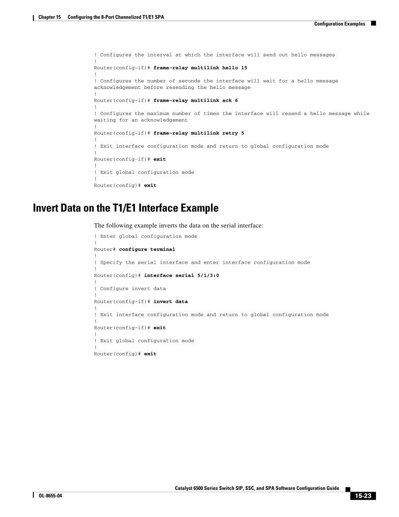
! Configures the interval at which the interface will send out hello messages!Router(config-if)# frame-relay multilink hello 15!! Configures the number of seconds the interface will wait for a hello message acknowledgement before resending the hello message!Router(config-if)# frame-relay multilink ack 6!! Configures the maximum number of times the interface will resend a hello message while waiting for an acknowledgement!Router(config-if)# frame-relay multilink retry 5!! Exit interface configuration mode and return to global configuration mode!Router(config-if)# exit!! Exit global configuration mode!Router(config)# exit
Invert Data on the T1/E1 Interface ExampleThe following example inverts the data on the serial interface:
! Enter global configuration mode!Router# configure terminal!! Specify the serial interface and enter interface configuration mode!Router(config)# interface serial 5/1/3:0!! Configure invert data!Router(config-if)# invert data!! Exit interface configuration mode and return to global configuration mode!Router(config-if)# exit!! Exit global configuration mode!Router(config)# exit
15-23Catalyst 6500 Series Switch SIP, SSC, and SPA Software Configuration Guide
OL-8655-04

Chapter 15 Configuring the 8-Port Channelized T1/E1 SPA Configuration Examples
15-24Catalyst 6500 Series Switch SIP, SSC, and SPA Software Configuration Guide
OL-8655-04