Configuring IP SLAs UDP Jitter Operations for VoIP · ConfiguringIPSLAsUDPJitterOperationsfor VoIP...
18
Configuring IP SLAs UDP Jitter Operations for VoIP This document describes how to configure an IP Service Level Agreements (SLAs) User Datagram Protocol (UDP) jitter operation to proactively monitor Voice over IP (VoIP) quality levels in your network, allowing you to guarantee VoIP quality levels to your users in IPv4 or IPv6 networks. The IP SLAs VoIP UDP jitter operation accurately simulates VoIP traffic using common codecs and calculates consistent voice quality scores (MOS and ICPIF) between Cisco devices in the network. The term “Voice” in this document should be taken to mean any Internet telephony applications. The term “Voice over IP” can include the transmission of multimedia (both voice and video) over IP networks. Note • Finding Feature Information, on page 1 • Restrictions for IP SLAs UDP Jitter Operations for VoIP, on page 2 • Information About IP SLAs UDP Jitter Operations for VoIP, on page 2 • How to Configure IP SLAs UDP Jitter Operations for VoIP, on page 7 • Configuration Examples for IP SLAs UDP Jitter Operations for VoIP, on page 14 • Additional References, on page 16 • Feature Information for IP SLAs VoIP UDP Jitter Operations, on page 17 • Glossary, on page 18 Finding Feature Information Your software release may not support all the features documented in this module. For the latest caveats and feature information, see Bug Search Tool and the release notes for your platform and software release. To find information about the features documented in this module, and to see a list of the releases in which each feature is supported, see the feature information table. Use Cisco Feature Navigator to find information about platform support and Cisco software image support. To access Cisco Feature Navigator, go to www.cisco.com/go/cfn. An account on Cisco.com is not required. Configuring IP SLAs UDP Jitter Operations for VoIP 1
Transcript of Configuring IP SLAs UDP Jitter Operations for VoIP · ConfiguringIPSLAsUDPJitterOperationsfor VoIP...
Configuring IP SLAs UDP Jitter Operations forVoIP
This document describes how to configure an IP Service Level Agreements (SLAs) User Datagram Protocol(UDP) jitter operation to proactively monitor Voice over IP (VoIP) quality levels in your network, allowingyou to guarantee VoIP quality levels to your users in IPv4 or IPv6 networks. The IP SLAs VoIP UDP jitteroperation accurately simulates VoIP traffic using common codecs and calculates consistent voice qualityscores (MOS and ICPIF) between Cisco devices in the network.
The term “Voice” in this document should be taken to mean any Internet telephony applications. The term“Voice over IP” can include the transmission of multimedia (both voice and video) over IP networks.
Note
• Finding Feature Information, on page 1• Restrictions for IP SLAs UDP Jitter Operations for VoIP, on page 2• Information About IP SLAs UDP Jitter Operations for VoIP, on page 2• How to Configure IP SLAs UDP Jitter Operations for VoIP, on page 7• Configuration Examples for IP SLAs UDP Jitter Operations for VoIP, on page 14• Additional References, on page 16• Feature Information for IP SLAs VoIP UDP Jitter Operations, on page 17• Glossary, on page 18
Finding Feature InformationYour software release may not support all the features documented in this module. For the latest caveats andfeature information, see Bug Search Tool and the release notes for your platform and software release. Tofind information about the features documented in this module, and to see a list of the releases in which eachfeature is supported, see the feature information table.
Use Cisco Feature Navigator to find information about platform support and Cisco software image support.To access Cisco Feature Navigator, go to www.cisco.com/go/cfn. An account on Cisco.com is not required.
Configuring IP SLAs UDP Jitter Operations for VoIP1
Restrictions for IP SLAs UDP Jitter Operations for VoIP• This feature uses UDP traffic to generate approximate Voice over IP scores. It does not provide supportfor the Real-Time Transport Protocol (RTP).
• ICPIF and MOS values provided by this feature, while consistent within IP SLAs, are estimates onlyand are intended only for relative comparisons. The values may not match values determined using othermethods.
• Predictions of customer opinion (such as those listed for the E-Model transmission rating factor R andderived Mean Opinion Scores) determined by any method are intended only for transmission planningand analysis purposes and should not be interpreted as reflecting actual customer opinions.
Information About IP SLAs UDP Jitter Operations for VoIP
The Calculated Planning Impairment Factor (ICPIF)The ICPIF originated in the 1996 version of ITU-T recommendation G.113, “Transmission impairments,” aspart of the formula Icpif = Itot - A. ICPIF is actually an acronym for “(Impairment) Calculated PlanningImpairment Factor,” but should be taken to simply mean the “calculated planning impairment factor.” TheICPIF attempts to quantify, for comparison and planning purposes, the key impairments to voice quality thatare encountered in the network.
The ICPIF is the sum of measured impairment factors (total impairments, or Itot ) minus a user-defined accessAdvantage Factor (A ) that is intended to represent the user’s expectations, based on how the call was placed(for example, a mobile call versus a land-line call). In its expanded form, the full formula is expressed as:
Icpif = Io + Iq + Idte + Idd + Ie - A
where
• Io represents impairments caused by non-optimal loudness rating,
• Iq represents impairments caused by PCM quantizing distortion,
• Idte represents impairments caused by talker echo,
• Idd represents impairments caused by one-way transmission times (one-way delay),
• Ie represents impairments caused by equipment effects, such as the type of codec used for the call andpacket loss, and
• A represents an access Advantage Factor (also called the user Expectation Factor) that compensates forthe fact that users may accept some degradation in quality in return for ease of access.
ICPIF values are expressed in a typical range of 5 (very low impairment) to 55 (very high impairment). ICPIFvalues numerically less than 20 are generally considered “adequate.”While intended to be an objectivemeasureof voice quality, the ICPIF value is also used to predict the subjective effect of combinations of impairments.The table below, taken from G.113 (02/96), shows how sample ICPIF values are expected to correspond tosubjective quality judgement.
Configuring IP SLAs UDP Jitter Operations for VoIP2
Configuring IP SLAs UDP Jitter Operations for VoIPRestrictions for IP SLAs UDP Jitter Operations for VoIP
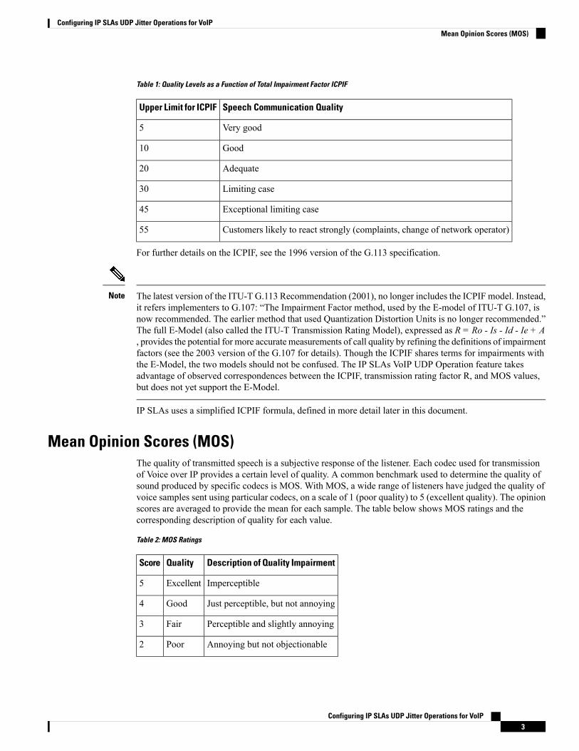
Table 1: Quality Levels as a Function of Total Impairment Factor ICPIF
Speech Communication QualityUpper Limit for ICPIF
Very good5
Good10
Adequate20
Limiting case30
Exceptional limiting case45
Customers likely to react strongly (complaints, change of network operator)55
For further details on the ICPIF, see the 1996 version of the G.113 specification.
The latest version of the ITU-T G.113 Recommendation (2001), no longer includes the ICPIF model. Instead,it refers implementers to G.107: “The Impairment Factor method, used by the E-model of ITU-T G.107, isnow recommended. The earlier method that used Quantization Distortion Units is no longer recommended.”The full E-Model (also called the ITU-T Transmission Rating Model), expressed as R = Ro - Is - Id - Ie + A, provides the potential for more accurate measurements of call quality by refining the definitions of impairmentfactors (see the 2003 version of the G.107 for details). Though the ICPIF shares terms for impairments withthe E-Model, the two models should not be confused. The IP SLAs VoIP UDP Operation feature takesadvantage of observed correspondences between the ICPIF, transmission rating factor R, and MOS values,but does not yet support the E-Model.
Note
IP SLAs uses a simplified ICPIF formula, defined in more detail later in this document.
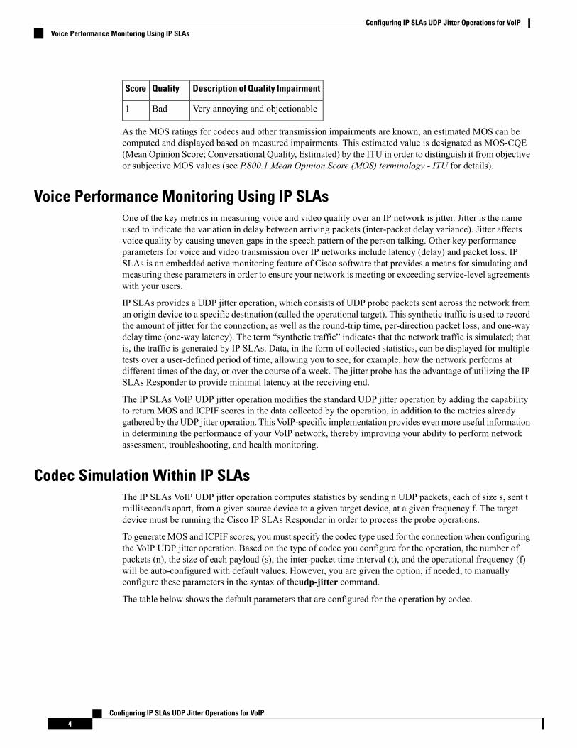
Mean Opinion Scores (MOS)The quality of transmitted speech is a subjective response of the listener. Each codec used for transmissionof Voice over IP provides a certain level of quality. A common benchmark used to determine the quality ofsound produced by specific codecs is MOS. With MOS, a wide range of listeners have judged the quality ofvoice samples sent using particular codecs, on a scale of 1 (poor quality) to 5 (excellent quality). The opinionscores are averaged to provide the mean for each sample. The table below shows MOS ratings and thecorresponding description of quality for each value.
Table 2: MOS Ratings
Description of Quality ImpairmentQualityScore
ImperceptibleExcellent5
Just perceptible, but not annoyingGood4
Perceptible and slightly annoyingFair3
Annoying but not objectionablePoor2
Configuring IP SLAs UDP Jitter Operations for VoIP3
Configuring IP SLAs UDP Jitter Operations for VoIPMean Opinion Scores (MOS)
Description of Quality ImpairmentQualityScore
Very annoying and objectionableBad1
As the MOS ratings for codecs and other transmission impairments are known, an estimated MOS can becomputed and displayed based on measured impairments. This estimated value is designated as MOS-CQE(Mean Opinion Score; Conversational Quality, Estimated) by the ITU in order to distinguish it from objectiveor subjective MOS values (see P.800.1 Mean Opinion Score (MOS) terminology - ITU for details).
Voice Performance Monitoring Using IP SLAsOne of the key metrics in measuring voice and video quality over an IP network is jitter. Jitter is the nameused to indicate the variation in delay between arriving packets (inter-packet delay variance). Jitter affectsvoice quality by causing uneven gaps in the speech pattern of the person talking. Other key performanceparameters for voice and video transmission over IP networks include latency (delay) and packet loss. IPSLAs is an embedded active monitoring feature of Cisco software that provides a means for simulating andmeasuring these parameters in order to ensure your network is meeting or exceeding service-level agreementswith your users.
IP SLAs provides a UDP jitter operation, which consists of UDP probe packets sent across the network froman origin device to a specific destination (called the operational target). This synthetic traffic is used to recordthe amount of jitter for the connection, as well as the round-trip time, per-direction packet loss, and one-waydelay time (one-way latency). The term “synthetic traffic” indicates that the network traffic is simulated; thatis, the traffic is generated by IP SLAs. Data, in the form of collected statistics, can be displayed for multipletests over a user-defined period of time, allowing you to see, for example, how the network performs atdifferent times of the day, or over the course of a week. The jitter probe has the advantage of utilizing the IPSLAs Responder to provide minimal latency at the receiving end.
The IP SLAs VoIP UDP jitter operation modifies the standard UDP jitter operation by adding the capabilityto return MOS and ICPIF scores in the data collected by the operation, in addition to the metrics alreadygathered by the UDP jitter operation. This VoIP-specific implementation provides evenmore useful informationin determining the performance of your VoIP network, thereby improving your ability to perform networkassessment, troubleshooting, and health monitoring.
Codec Simulation Within IP SLAsThe IP SLAs VoIP UDP jitter operation computes statistics by sending n UDP packets, each of size s, sent tmilliseconds apart, from a given source device to a given target device, at a given frequency f. The targetdevice must be running the Cisco IP SLAs Responder in order to process the probe operations.
To generateMOS and ICPIF scores, you must specify the codec type used for the connection when configuringthe VoIP UDP jitter operation. Based on the type of codec you configure for the operation, the number ofpackets (n), the size of each payload (s), the inter-packet time interval (t), and the operational frequency (f)will be auto-configured with default values. However, you are given the option, if needed, to manuallyconfigure these parameters in the syntax of theudp-jitter command.
The table below shows the default parameters that are configured for the operation by codec.
Configuring IP SLAs UDP Jitter Operations for VoIP4
Configuring IP SLAs UDP Jitter Operations for VoIPVoice Performance Monitoring Using IP SLAs

Table 3: Default VoIP UDP Jitter Operation Parameters by Codec
Frequency of ProbeOperations (f)
Default Numberof Packets (n)
Default IntervalBetween Packets(t)
Default Request Size(Packet Payload) (s)
Codec
Once every 1 minute100020 ms160 + 12 RTP bytesG.711 mu-Law(g711ulaw)
Once every 1 minute100020 ms160 + 12 RTP bytesG.711 A-Law(g711alaw)
Once every 1 minute100020 ms20 + 12 RTP bytesG.729A (g729a)
For example, if you configure the VoIP UDP jitter operation to use the characteristics for the g711ulaw codec,by default a probe operation will be sent once a minute (f). Each probe operation would consist of 1000 packets(n), with each packet containing 180 bytes of synthetic data (s), sent 20 milliseconds apart (t).
The IP SLAs ICPIF ValueICPIF value computation with Cisco software is based primarily on the two main factors that can impair voicequality: delayed packets and lost packets. Because packet delay and packet loss can be measured by IP SLAs,the full ICPIF formula, Icpif = Io + Iq + Idte + Idd + Ie - A, is simplified by assuming the values of Io , Iq ,and Idte are zero, resulting in the following formula:
Total Impairment Factor (Icpif) = Delay Impairment Factor (Idd) + Equipment Impairment Factor (Ie) -Expectation/Advantage Factor (A)
This means that the ICPIF value is computed by adding a Delay Impairment Factor, which is based on ameasurement of delayed packets, and an Equipment Impairment Factor, which is based on a measurement oflost packets. From this sum of the total impairments measured in the network, an impairment variable (theExpectation Factor) is subtracted to yield the ICPIF.
This is the same formula used by Cisco Gateways to calculate the ICPIF for received VoIP data streams.
The Delay Impairment Factor
The Delay Impairment Factor (Idd ) is a number based on two values. One value is fixed and is derived usingthe static values (as defined in the ITU standards) for Codec Delay, Look Ahead Delay, and Digital SignalProcessing (DSP) Delay. The second value is variable and is based on the measured one-way delay (round-triptime measurement divided by 2). The one-way delay value is mapped to a number using a mapping table thatis based on a G.107 (2002 version) analytic expression. The table below shows sample correspondencesbetween the one-way delay measured by IP SLAs and Delay Impairment Factor values.
Table 4: Sample Correspondence of One-Way Delay to ICPIF Delay Impairment
Delay Impairment FactorOne-Way Delay (ms)
150
2100
4150
Configuring IP SLAs UDP Jitter Operations for VoIP5
Configuring IP SLAs UDP Jitter Operations for VoIPThe IP SLAs ICPIF Value

Delay Impairment FactorOne-Way Delay (ms)
7200
The Equipment Impairment Factor
The Equipment Impairment Factor (Ie) is a number based on the amount of measured packet loss. The amountof measured packet loss, expressed as a percentage of total number of packets sent, corresponds an EquipmentImpairment Factor that is defined by codec. The table below shows sample correspondences between thepacket loss measured by IP SLAs and Equipment Impairment Factor values.
Table 5: Sample Correspondence of Measured Packet Loss to ICPIF Equipment Impairment
Equipment Impairment Value for theCS-ACELP (G.729A) Codec
Equipment Impairment Value forPCM (G.711) Codecs
Packet Loss (as a percentage oftotal number of packets sent)
20122%
30224%
38286%
42328%
The Expectation Factor
The Expectation Factor, also called the Advantage Factor (A), is intended to represent the fact that users mayaccept some degradation in quality in return for ease of access. For example, a mobile phone user in ahard-to-reach location may have an expectation that the connection quality will not be as good as a traditionalland-line connection. This variable is also called the Advantage Factor (short for Access Advantage Factor)because it attempts to balance an increased access advantage against a decline in voice quality.
The table below, adapted from ITU-T Rec. G.113, defines a set of provisional maximum values for A in termsof the service provided.
Table 6: Advantage Factor Recommended Maximum Values
Advantage / Expectation Factor:
Maximum value of A
Communication Service
0Conventional wire-line (land-line)
5Mobility (cellular connections) within a building
10Mobility within a Geographical area or moving in a vehicle
20Access to hard-to-reach location; (for example, via multi-hop satelliteconnections)
These values are only suggestions. To be meaningful, the use of the factor A and its selected value in a specificapplication should be used consistently in any planning model you adopt. However, the values in the tableabove should be considered as the absolute upper limits for A .
Configuring IP SLAs UDP Jitter Operations for VoIP6
Configuring IP SLAs UDP Jitter Operations for VoIPThe IP SLAs ICPIF Value
The default Advantage Factor for IP SLAs VoIP UDP jitter operations is always zero.
The IP SLAs MOS ValueIP SLAs uses an observed correspondence between ICPIF and MOS values to estimate an MOS value. Usageof the abbreviation MOS within the context of this feature should be taken to represent the MOS-CQE (MeanOpinion Score; Conversational Quality, Estimated).
The E model, as defined in G.107 (03/2003), predicts the subjective quality that is experienced by an averagelistener by combining the impairment caused by transmission parameters (such as loss and delay) into a singlerating, the transmission rating factor R (the R Factor). This rating, expressed in a scale of 0 (worst) to 100(best) can be used to predict subjective user reactions, such as theMOS. Specifically, theMOS can be obtainedfrom the R Factor with a converting formula. Conversely, a modified inverted form can be used to calculateR Factors from MOS values.
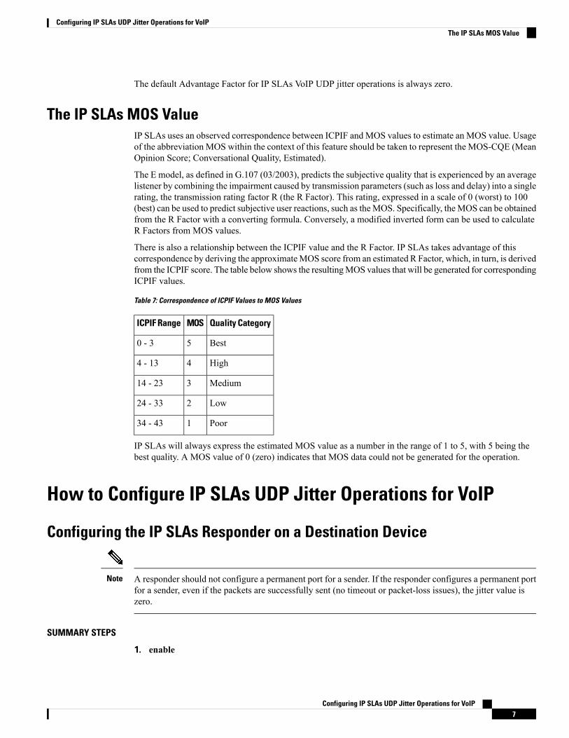
There is also a relationship between the ICPIF value and the R Factor. IP SLAs takes advantage of thiscorrespondence by deriving the approximateMOS score from an estimated R Factor, which, in turn, is derivedfrom the ICPIF score. The table below shows the resultingMOS values that will be generated for correspondingICPIF values.
Table 7: Correspondence of ICPIF Values to MOS Values
Quality CategoryMOSICPIF Range
Best50 - 3
High44 - 13
Medium314 - 23
Low224 - 33
Poor134 - 43
IP SLAs will always express the estimated MOS value as a number in the range of 1 to 5, with 5 being thebest quality. A MOS value of 0 (zero) indicates that MOS data could not be generated for the operation.
How to Configure IP SLAs UDP Jitter Operations for VoIP
Configuring the IP SLAs Responder on a Destination Device
A responder should not configure a permanent port for a sender. If the responder configures a permanent portfor a sender, even if the packets are successfully sent (no timeout or packet-loss issues), the jitter value iszero.
Note
SUMMARY STEPS
1. enable
Configuring IP SLAs UDP Jitter Operations for VoIP7
Configuring IP SLAs UDP Jitter Operations for VoIPThe IP SLAs MOS Value

2. configure terminal3. Enter one of the following commands:
• ip sla responder• ip sla responder udp-echo ipaddress ip-address port portvrf vrf
4. end
DETAILED STEPS
PurposeCommand or Action
Enables privileged EXEC mode.enableStep 1
Example: • Enter your password if prompted.
Device> enable
Enters global configuration mode.configure terminal
Example:
Step 2
Device# configure terminal
(Optional) Temporarily enables IP SLAs responderfunctionality on a Cisco device in response to controlmessages from the source.
Enter one of the following commands:Step 3
• ip sla responder• ip sla responder udp-echo ipaddress ip-address portportvrf vrf (Optional; required only if protocol control is disabled on
the source.) Enables IP SLAs responder functionality onthe specified IP address, port and VRF.Example:
Device(config)# ip sla responder • Protocol control is enabled by default.
Device(config)# ip sla responder udp-echo ipaddress192.0.2.132 port 5000 vrf vrf1
Exits global configuration mode and returns to privilegedEXEC mode.
end
Example:
Step 4
Device(config)# end
Configuring IP SLAs UDP Jitter Operations for VoIP8
Configuring IP SLAs UDP Jitter Operations for VoIPConfiguring the IP SLAs Responder on a Destination Device
Configuring and Scheduling an IP SLAs VoIP UDP Jitter Operation
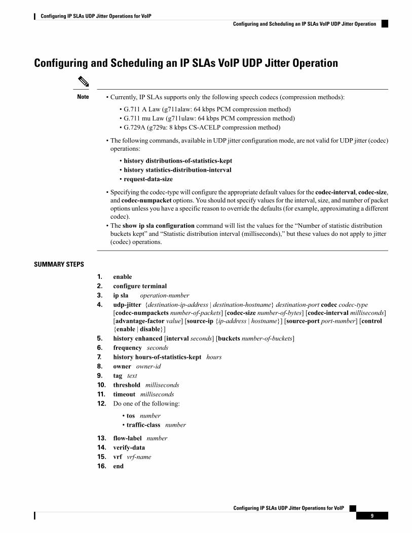
• Currently, IP SLAs supports only the following speech codecs (compression methods):
• G.711 A Law (g711alaw: 64 kbps PCM compression method)• G.711 mu Law (g711ulaw: 64 kbps PCM compression method)• G.729A (g729a: 8 kbps CS-ACELP compression method)
• The following commands, available in UDP jitter configuration mode, are not valid for UDP jitter (codec)operations:
• history distributions-of-statistics-kept• history statistics-distribution-interval• request-data-size
• Specifying the codec-type will configure the appropriate default values for the codec-interval, codec-size,and codec-numpacket options. You should not specify values for the interval, size, and number of packetoptions unless you have a specific reason to override the defaults (for example, approximating a differentcodec).
• The show ip sla configuration command will list the values for the “Number of statistic distributionbuckets kept” and “Statistic distribution interval (milliseconds),” but these values do not apply to jitter(codec) operations.
Note
SUMMARY STEPS
1. enable2. configure terminal3. ip sla operation-number4. udp-jitter {destination-ip-address | destination-hostname} destination-port codec codec-type
[codec-numpackets number-of-packets] [codec-size number-of-bytes] [codec-interval milliseconds][advantage-factor value] [source-ip {ip-address | hostname}] [source-port port-number] [control{enable | disable}]
5. history enhanced [interval seconds] [buckets number-of-buckets]6. frequency seconds7. history hours-of-statistics-kept hours8. owner owner-id9. tag text10. threshold milliseconds11. timeout milliseconds12. Do one of the following:
• tos number• traffic-class number
13. flow-label number14. verify-data15. vrf vrf-name16. end
Configuring IP SLAs UDP Jitter Operations for VoIP9
Configuring IP SLAs UDP Jitter Operations for VoIPConfiguring and Scheduling an IP SLAs VoIP UDP Jitter Operation

17. show ip sla configuration [operation-number]
DETAILED STEPS
PurposeCommand or Action
Enables privileged EXEC mode.enableStep 1
Example: • Enter your password if prompted.
Device> enable
Enters global configuration mode.configure terminal
Example:
Step 2
Device# configure terminal
Begins configuration for an IP SLAs operation and entersIP SLA configuration mode.
ip sla operation-number
Example:
Step 3
Device(config)# ip sla 10
Configures the operation as a jitter (codec) operation thatwill generate VoIP scores in addition to latency, jitter, andpacket loss statistics.
udp-jitter {destination-ip-address | destination-hostname}destination-port codec codec-type [codec-numpacketsnumber-of-packets] [codec-size number-of-bytes][codec-interval milliseconds] [advantage-factor value]
Step 4
[source-ip {ip-address | hostname}] [source-portport-number] [control {enable | disable}]
Example:
Device(config-ip-sla)# udp-jitter 209.165.200.22516384 codec g711alaw advantage-factor 10
(Optional) Enables enhanced history gathering for an IPSLAs operation.
history enhanced [interval seconds] [bucketsnumber-of-buckets]
Example:
Step 5
Device(config-ip-sla-jitter)# history enhancedinterval 900 buckets 100
(Optional) Sets the rate at which a specified IP SLAsoperation repeats.
frequency seconds
Example:
Step 6
Device(config-ip-sla-jitter)# frequency 30
(Optional) Sets the number of hours for which statisticsare maintained for an IP SLAs operation.
history hours-of-statistics-kept hours
Example:
Step 7
Device(config-ip-sla-jitter)# historyhours-of-statistics-kept 4
Configuring IP SLAs UDP Jitter Operations for VoIP10
Configuring IP SLAs UDP Jitter Operations for VoIPConfiguring and Scheduling an IP SLAs VoIP UDP Jitter Operation

PurposeCommand or Action
(Optional) Configures the Simple Network ManagementProtocol (SNMP) owner of an IP SLAs operation.
owner owner-id
Example:
Step 8
Device(config-ip-sla-jitter)# owner admin
(Optional) Creates a user-specified identifier for an IPSLAs operation.
tag text
Example:
Step 9
Device(config-ip-sla-jitter)# tagTelnetPollServer1
(Optional) Sets the upper threshold value for calculatingnetwork monitoring statistics created by an IP SLAsoperation.
threshold milliseconds
Example:
Device(config-ip-sla-jitter)# threshold 10000
Step 10
(Optional) Sets the amount of time an IP SLAs operationwaits for a response from its request packet.
timeout milliseconds
Example:
Step 11
Device(config-ip-sla-jitter)# timeout 10000
(Optional) In an IPv4 network only, defines the ToS bytein the IPv4 header of an IP SLAs operation.
Do one of the following:Step 12
• tos numberor• traffic-class number(Optional) In an IPv6 network only, defines the trafficclass byte in the IPv6 header for a supported IP SLAsoperation.
Example:
Device(config-ip-sla-jitter)# tos 160
Example:
Device(config-ip-sla-jitter)# traffic-class 160
(Optional) In an IPv6 network only, defines the flow labelfield in the IPv6 header for a supported IP SLAs operation.
flow-label number
Example:
Step 13
Device(config-ip-sla-jitter)# flow-label 112233
(Optional) Causes an IP SLAs operation to check eachreply packet for data corruption.
verify-data
Example:
Step 14
Device(config-ip-sla-jitter)# verify-data
(Optional) Allows monitoring withinMultiprotocol LabelSwitching (MPLS) Virtual Private Networks (VPNs) usingIP SLAs operations.
vrf vrf-name
Example:
Device(config-ip-sla-jitter)# vrf vpn-A
Step 15
Configuring IP SLAs UDP Jitter Operations for VoIP11
Configuring IP SLAs UDP Jitter Operations for VoIPConfiguring and Scheduling an IP SLAs VoIP UDP Jitter Operation
PurposeCommand or Action
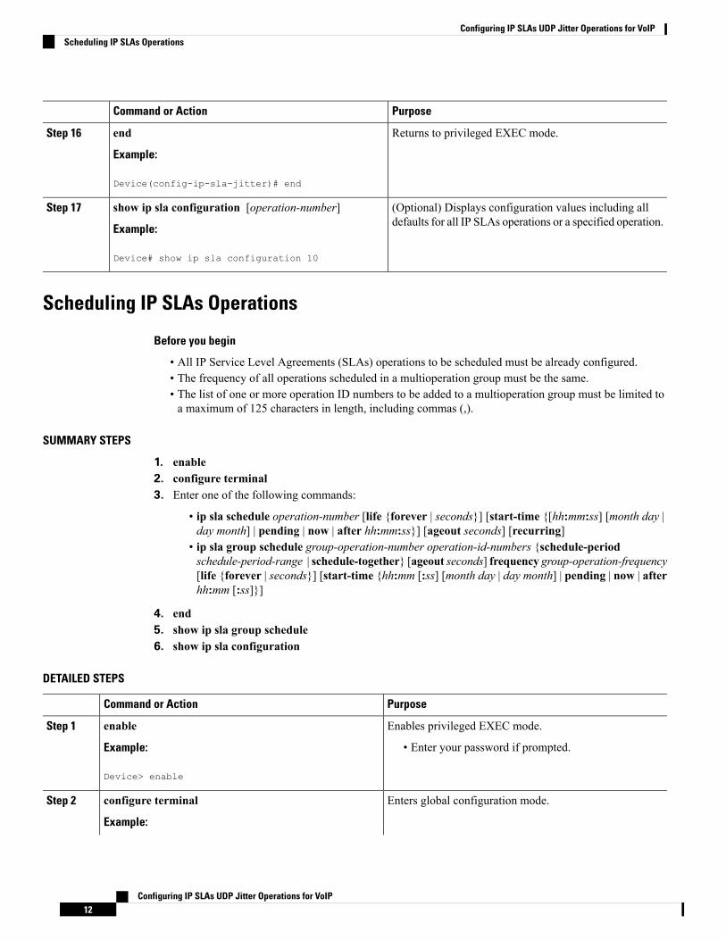
Returns to privileged EXEC mode.end
Example:
Step 16
Device(config-ip-sla-jitter)# end
(Optional) Displays configuration values including alldefaults for all IP SLAs operations or a specified operation.
show ip sla configuration [operation-number]
Example:
Step 17
Device# show ip sla configuration 10
Scheduling IP SLAs Operations
Before you begin
• All IP Service Level Agreements (SLAs) operations to be scheduled must be already configured.• The frequency of all operations scheduled in a multioperation group must be the same.• The list of one or more operation ID numbers to be added to a multioperation group must be limited toa maximum of 125 characters in length, including commas (,).
SUMMARY STEPS
1. enable2. configure terminal3. Enter one of the following commands:
• ip sla schedule operation-number [life {forever | seconds}] [start-time {[hh:mm:ss] [month day |day month] | pending | now | after hh:mm:ss}] [ageout seconds] [recurring]
• ip sla group schedule group-operation-number operation-id-numbers {schedule-periodschedule-period-range | schedule-together} [ageout seconds] frequency group-operation-frequency[life {forever | seconds}] [start-time {hh:mm [:ss] [month day | day month] | pending | now | afterhh:mm [:ss]}]
4. end5. show ip sla group schedule6. show ip sla configuration
DETAILED STEPS
PurposeCommand or Action
Enables privileged EXEC mode.enableStep 1
Example: • Enter your password if prompted.
Device> enable
Enters global configuration mode.configure terminal
Example:
Step 2
Configuring IP SLAs UDP Jitter Operations for VoIP12
Configuring IP SLAs UDP Jitter Operations for VoIPScheduling IP SLAs Operations

PurposeCommand or Action
Device# configure terminal
Enter one of the following commands:Step 3 • Configures the scheduling parameters for an individualIP SLAs operation.• ip sla schedule operation-number [life {forever |
seconds}] [start-time {[hh:mm:ss] [month day | day • Specifies an IP SLAs operation group number and therange of operation numbers for a multioperationscheduler.
month] | pending | now | after hh:mm:ss}] [ageoutseconds] [recurring]
• ip sla group schedule group-operation-numberoperation-id-numbers {schedule-periodschedule-period-range | schedule-together} [ageoutseconds] frequency group-operation-frequency [life{forever | seconds}] [start-time {hh:mm [:ss] [monthday | day month] | pending | now | after hh:mm [:ss]}]
Example:
Device(config)# ip sla schedule 10 life foreverstart-time now
Device(config)# ip sla group schedule 10schedule-period frequency
Device(config)# ip sla group schedule 1 3,4,6-9life forever start-time now
Device(config)# ip sla schedule 1 3,4,6-9schedule-period 50 frequency range 80-100
Exits global configuration mode and returns to privilegedEXEC mode.
end
Example:
Step 4
Device(config)# end
(Optional) Displays IP SLAs group schedule details.show ip sla group schedule
Example:
Step 5
Device# show ip sla group schedule
(Optional) Displays IP SLAs configuration details.show ip sla configuration
Example:
Step 6
Device# show ip sla configuration
Troubleshooting Tips• If the IP Service Level Agreements (SLAs) operation is not running and not generating statistics, addthe verify-data command to the configuration (while configuring in IP SLA configuration mode) toenable data verification. When data verification is enabled, each operation response is checked for
Configuring IP SLAs UDP Jitter Operations for VoIP13
Configuring IP SLAs UDP Jitter Operations for VoIPTroubleshooting Tips
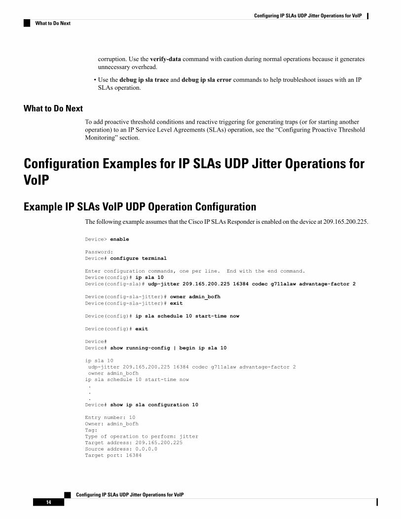
corruption. Use the verify-data command with caution during normal operations because it generatesunnecessary overhead.
• Use the debug ip sla trace and debug ip sla error commands to help troubleshoot issues with an IPSLAs operation.
What to Do NextTo add proactive threshold conditions and reactive triggering for generating traps (or for starting anotheroperation) to an IP Service Level Agreements (SLAs) operation, see the “Configuring Proactive ThresholdMonitoring” section.
Configuration Examples for IP SLAs UDP Jitter Operations forVoIP
Example IP SLAs VoIP UDP Operation ConfigurationThe following example assumes that the Cisco IP SLAs Responder is enabled on the device at 209.165.200.225.
Device> enable
Password:Device# configure terminal
Enter configuration commands, one per line. End with the end command.Device(config)# ip sla 10Device(config-sla)# udp-jitter 209.165.200.225 16384 codec g711alaw advantage-factor 2
Device(config-sla-jitter)# owner admin_bofhDevice(config-sla-jitter)# exit
Device(config)# ip sla schedule 10 start-time now
Device(config)# exit
Device#Device# show running-config | begin ip sla 10
ip sla 10udp-jitter 209.165.200.225 16384 codec g711alaw advantage-factor 2owner admin_bofhip sla schedule 10 start-time now...Device# show ip sla configuration 10
Entry number: 10Owner: admin_bofhTag:Type of operation to perform: jitterTarget address: 209.165.200.225Source address: 0.0.0.0Target port: 16384
Configuring IP SLAs UDP Jitter Operations for VoIP14
Configuring IP SLAs UDP Jitter Operations for VoIPWhat to Do Next
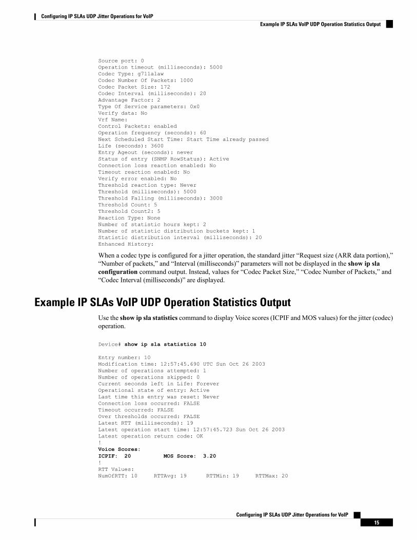
Source port: 0Operation timeout (milliseconds): 5000Codec Type: g711alawCodec Number Of Packets: 1000Codec Packet Size: 172Codec Interval (milliseconds): 20Advantage Factor: 2Type Of Service parameters: 0x0Verify data: NoVrf Name:Control Packets: enabledOperation frequency (seconds): 60Next Scheduled Start Time: Start Time already passedLife (seconds): 3600Entry Ageout (seconds): neverStatus of entry (SNMP RowStatus): ActiveConnection loss reaction enabled: NoTimeout reaction enabled: NoVerify error enabled: NoThreshold reaction type: NeverThreshold (milliseconds): 5000Threshold Falling (milliseconds): 3000Threshold Count: 5Threshold Count2: 5Reaction Type: NoneNumber of statistic hours kept: 2Number of statistic distribution buckets kept: 1Statistic distribution interval (milliseconds): 20Enhanced History:
When a codec type is configured for a jitter operation, the standard jitter “Request size (ARR data portion),”“Number of packets,” and “Interval (milliseconds)” parameters will not be displayed in the show ip slaconfiguration command output. Instead, values for “Codec Packet Size,” “Codec Number of Packets,” and“Codec Interval (milliseconds)” are displayed.
Example IP SLAs VoIP UDP Operation Statistics OutputUse the show ip sla statistics command to display Voice scores (ICPIF andMOS values) for the jitter (codec)operation.
Device# show ip sla statistics 10
Entry number: 10Modification time: 12:57:45.690 UTC Sun Oct 26 2003Number of operations attempted: 1Number of operations skipped: 0Current seconds left in Life: ForeverOperational state of entry: ActiveLast time this entry was reset: NeverConnection loss occurred: FALSETimeout occurred: FALSEOver thresholds occurred: FALSELatest RTT (milliseconds): 19Latest operation start time: 12:57:45.723 Sun Oct 26 2003Latest operation return code: OK!Voice Scores:ICPIF: 20 MOS Score: 3.20!RTT Values:NumOfRTT: 10 RTTAvg: 19 RTTMin: 19 RTTMax: 20
Configuring IP SLAs UDP Jitter Operations for VoIP15
Configuring IP SLAs UDP Jitter Operations for VoIPExample IP SLAs VoIP UDP Operation Statistics Output

RTTSum: 191 RTTSum2: 3649Packet Loss Values:PacketLossSD: 0 PacketLossDS: 0PacketOutOfSequence: 0 PacketMIA: 0 PacketLateArrival: 0InternalError: 0 Busies: 0Jitter Values:NumOfJitterSamples: 9MinOfPositivesSD: 0 MaxOfPositivesSD: 0NumOfPositivesSD: 0 SumOfPositivesSD: 0 Sum2PositivesSD: 0MinOfNegativesSD: 0 MaxOfNegativesSD: 0NumOfNegativesSD: 0 SumOfNegativesSD: 0 Sum2NegativesSD: 0MinOfPositivesDS: 1 MaxOfPositivesDS: 1NumOfPositivesDS: 1 SumOfPositivesDS: 1 Sum2PositivesDS: 1MinOfNegativesDS: 1 MaxOfNegativesDS: 1NumOfNegativesDS: 1 SumOfNegativesDS: 1 Sum2NegativesDS: 1Interarrival jitterout: 0 Interarrival jitterin: 0One Way Values:NumOfOW: 0OWMinSD: 0 OWMaxSD: 0 OWSumSD: 0 OWSum2SD: 0OWMinDS: 0 OWMaxDS: 0 OWSumDS: 0 OWSum2DS: 0
Additional ReferencesRelated Documents
Document TitleRelated Topic
Cisco IOS Master Commands List, All ReleasesCisco IOS commands
Cisco IOS IP SLAs Command ReferenceCisco IOS IP SLAs commands
Understanding Codecs: Complexity, Hardware Support, MOS, andNegotiation
Voice over IP (VoIP) codecs
Understanding Jitter in Packet Voice Networks (Cisco IOS Platforms)shtml
Jitter in Packet Voice Networks
Standards and RFCs
TitleStandard1/RFC2
The E-model, a computation model for use in transmissionplanning
ITU-T Recommendation G.107 (2003)
Transmission impairmentsITU-T Recommendation G.113 (1996)
Transmission impairments due to speech processingITU-T Recommendation G.113 (2001)
Pulse code modulation (PCM) of voice frequencies (alsoknown as the G.711 Voice Codec)
ITU-T Recommendation G.711 (1998)
Reduced complexity 8 kbit/s CS-ACELP speech codec (alsoknown as the G.729/A/B Speech Codec)
ITU-T Recommendation G.729 Annex A(1996)
Mean Opinion Score (MOS) terminologyITU-T Recommendation P.800.1 (2003)
Configuring IP SLAs UDP Jitter Operations for VoIP16
Configuring IP SLAs UDP Jitter Operations for VoIPAdditional References
TitleStandard1/RFC2
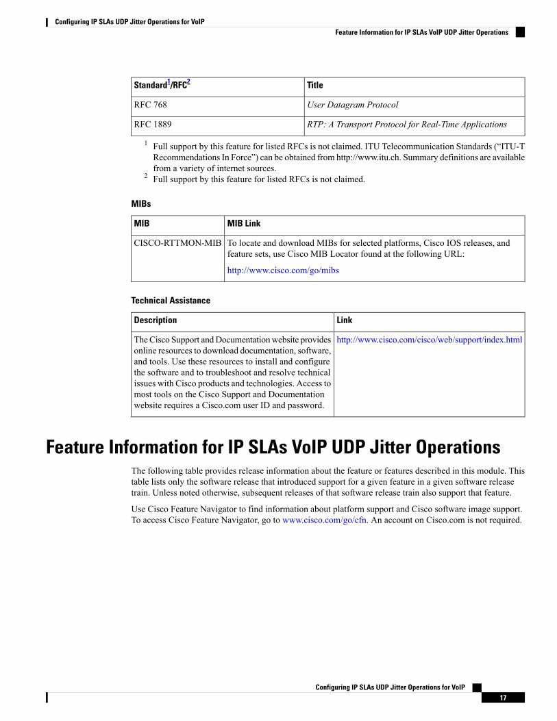
User Datagram ProtocolRFC 768
RTP: A Transport Protocol for Real-Time ApplicationsRFC 1889
1 Full support by this feature for listed RFCs is not claimed. ITU Telecommunication Standards (“ITU-TRecommendations In Force”) can be obtained from http://www.itu.ch. Summary definitions are availablefrom a variety of internet sources.
2 Full support by this feature for listed RFCs is not claimed.
MIBs
MIB LinkMIB
To locate and download MIBs for selected platforms, Cisco IOS releases, andfeature sets, use Cisco MIB Locator found at the following URL:
http://www.cisco.com/go/mibs
CISCO-RTTMON-MIB
Technical Assistance
LinkDescription
http://www.cisco.com/cisco/web/support/index.htmlTheCisco Support andDocumentationwebsite providesonline resources to download documentation, software,and tools. Use these resources to install and configurethe software and to troubleshoot and resolve technicalissues with Cisco products and technologies. Access tomost tools on the Cisco Support and Documentationwebsite requires a Cisco.com user ID and password.
Feature Information for IP SLAs VoIP UDP Jitter OperationsThe following table provides release information about the feature or features described in this module. Thistable lists only the software release that introduced support for a given feature in a given software releasetrain. Unless noted otherwise, subsequent releases of that software release train also support that feature.
Use Cisco Feature Navigator to find information about platform support and Cisco software image support.To access Cisco Feature Navigator, go to www.cisco.com/go/cfn. An account on Cisco.com is not required.
Configuring IP SLAs UDP Jitter Operations for VoIP17
Configuring IP SLAs UDP Jitter Operations for VoIPFeature Information for IP SLAs VoIP UDP Jitter Operations
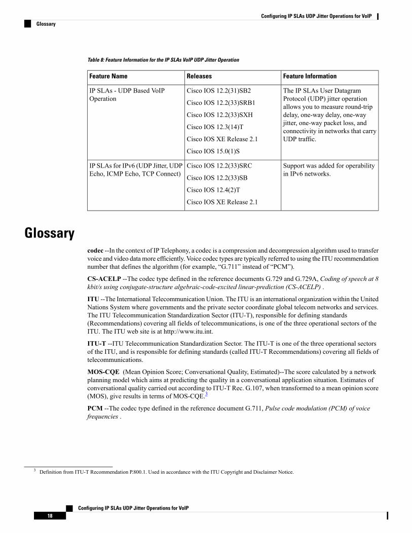
Table 8: Feature Information for the IP SLAs VoIP UDP Jitter Operation
Feature InformationReleasesFeature Name
The IP SLAs User DatagramProtocol (UDP) jitter operationallows you to measure round-tripdelay, one-way delay, one-wayjitter, one-way packet loss, andconnectivity in networks that carryUDP traffic.
Cisco IOS 12.2(31)SB2
Cisco IOS 12.2(33)SRB1
Cisco IOS 12.2(33)SXH
Cisco IOS 12.3(14)T
Cisco IOS XE Release 2.1
Cisco IOS 15.0(1)S
IP SLAs - UDP Based VoIPOperation
Support was added for operabilityin IPv6 networks.
Cisco IOS 12.2(33)SRC
Cisco IOS 12.2(33)SB
Cisco IOS 12.4(2)T
Cisco IOS XE Release 2.1
IP SLAs for IPv6 (UDP Jitter, UDPEcho, ICMP Echo, TCP Connect)
Glossarycodec --In the context of IP Telephony, a codec is a compression and decompression algorithm used to transfervoice and video data more efficiently. Voice codec types are typically referred to using the ITU recommendationnumber that defines the algorithm (for example, “G.711” instead of “PCM”).
CS-ACELP --The codec type defined in the reference documents G.729 and G.729A, Coding of speech at 8kbit/s using conjugate-structure algebraic-code-excited linear-prediction (CS-ACELP) .
ITU --The International Telecommunication Union. The ITU is an international organization within the UnitedNations System where governments and the private sector coordinate global telecom networks and services.The ITU Telecommunication Standardization Sector (ITU-T), responsible for defining standards(Recommendations) covering all fields of telecommunications, is one of the three operational sectors of theITU. The ITU web site is at http://www.itu.int.
ITU-T --ITU Telecommunication Standardization Sector. The ITU-T is one of the three operational sectorsof the ITU, and is responsible for defining standards (called ITU-T Recommendations) covering all fields oftelecommunications.
MOS-CQE (Mean Opinion Score; Conversational Quality, Estimated)--The score calculated by a networkplanning model which aims at predicting the quality in a conversational application situation. Estimates ofconversational quality carried out according to ITU-T Rec. G.107, when transformed to a mean opinion score(MOS), give results in terms of MOS-CQE.3
PCM --The codec type defined in the reference document G.711, Pulse code modulation (PCM) of voicefrequencies .
3 Definition from ITU-T Recommendation P.800.1. Used in accordance with the ITU Copyright and Disclaimer Notice.
Configuring IP SLAs UDP Jitter Operations for VoIP18
Configuring IP SLAs UDP Jitter Operations for VoIPGlossary