Configuring Firewall Load Balancing...11-3 Catalyst 6500 Series Content Switching Module...
26
CHAPTER 11-1 Catalyst 6500 Series Content Switching Module Installation and Configuration Note OL-4612-03 11 Configuring Firewall Load Balancing This chapter describes how to configure firewall load balancing and contains these sections: • Understanding How Firewalls Work, page 11-1 • Configuring Stealth Firewall Load Balancing, page 11-7 • Configuring Regular Firewall Load Balancing, page 11-16 • Configuring Reverse-Sticky for Firewalls, page 11-24 • Configuring Stateful Firewall Connection Remapping, page 11-26 Firewall load balancing allows you to scale firewall protection by distributing traffic across multiple firewalls on a per-connection basis. All packets belonging to a particular connection must go through the same firewall. The firewall then allows or denies transmission of individual packets across its interfaces. Understanding How Firewalls Work A firewall forms a physical barrier between two parts of a network, for example, the Internet and an intranet. When a firewall accepts a packet from one side (the Internet), it sends the packet through to the other side (the intranet). A firewall can modify a packet before passing it through or send it through unaltered. When a firewall rejects a packet, it usually drops the packet and logs the dropped packet as an event. After a session is established and a flow of packets begins, a firewall can monitor each packet in the flow or allow the flow to continue, unmonitored, depending on the policies that are configured on that firewall. This section contains the following: • Firewall Types, page 11-2 • How the CSM Distributes Traffic to Firewalls, page 11-2 • Supported Firewalls, page 11-2 • Layer 3 Load Balancing to Firewalls, page 11-2 • Types of Firewall Configurations, page 11-3 • IP Reverse-Sticky for Firewalls, page 11-3 • CSM Firewall Configurations, page 11-3 • Fault-Tolerant CSM Firewall Configurations, page 11-6
Transcript of Configuring Firewall Load Balancing...11-3 Catalyst 6500 Series Content Switching Module...

Catalyst 6500 Series Content Switching ModOL-4612-03
C H A P T E R 11
Configuring Firewall Load BalancingThis chapter describes how to configure firewall load balancing and contains these sections:
• Understanding How Firewalls Work, page 11-1
• Configuring Stealth Firewall Load Balancing, page 11-7
• Configuring Regular Firewall Load Balancing, page 11-16
• Configuring Reverse-Sticky for Firewalls, page 11-24
• Configuring Stateful Firewall Connection Remapping, page 11-26
Firewall load balancing allows you to scale firewall protection by distributing traffic across multiple firewalls on a per-connection basis. All packets belonging to a particular connection must go through the same firewall. The firewall then allows or denies transmission of individual packets across its interfaces.
Understanding How Firewalls WorkA firewall forms a physical barrier between two parts of a network, for example, the Internet and an intranet. When a firewall accepts a packet from one side (the Internet), it sends the packet through to the other side (the intranet). A firewall can modify a packet before passing it through or send it through unaltered. When a firewall rejects a packet, it usually drops the packet and logs the dropped packet as an event.
After a session is established and a flow of packets begins, a firewall can monitor each packet in the flow or allow the flow to continue, unmonitored, depending on the policies that are configured on that firewall.
This section contains the following:
• Firewall Types, page 11-2
• How the CSM Distributes Traffic to Firewalls, page 11-2
• Supported Firewalls, page 11-2
• Layer 3 Load Balancing to Firewalls, page 11-2
• Types of Firewall Configurations, page 11-3
• IP Reverse-Sticky for Firewalls, page 11-3
• CSM Firewall Configurations, page 11-3
• Fault-Tolerant CSM Firewall Configurations, page 11-6
11-1ule Installation and Configuration Note

Chapter 11 Configuring Firewall Load BalancingUnderstanding How Firewalls Work
Firewall TypesThe two basic types of firewalls are as follows:
• Regular firewalls
• Stealth firewalls
Regular firewalls have a presence on the network; they are assigned an IP address that allows them to be addressed as a device and seen by other devices on the network.
Stealth firewalls have no presence on the network; they are not assigned an IP address and cannot be addressed or seen by other devices on the network. To the network, a stealth firewall is part of the wire.
Both firewall types examine traffic moving in both directions (between the protected and the unprotected side of the network) and accept or reject packets based on user-defined sets of policies.
How the CSM Distributes Traffic to Firewalls The CSM load-balances traffic to devices configured in server farms. These devices can be servers, firewalls, or any IP-addressable object including an alias IP address. The CSM uses load-balancing algorithms to determine how the traffic is balanced among the devices configured in server farms, independent of device type.
Note We recommend that you configure Layer 3 load balancing on server farms that contain firewalls because of the interactions between higher-layer load-balancing algorithms and server applications.
Supported FirewallsThe CSM can load-balance traffic to regular or stealth firewalls.
For regular firewalls, a single CSM or a pair of CSMs balances traffic among firewalls that contain unique IP addresses, similar to how the CSM balances traffic to servers.
For stealth firewalls, a CSM balances traffic among unique VLAN alias IP address interfaces on another CSM that provides paths through stealth firewalls. A stealth firewall is configured so that all traffic moving in both directions across that VLAN moves through the firewall.
Layer 3 Load Balancing to Firewalls When the CSM load-balances traffic to firewalls, the CSM performs the same function that it performs when it load-balances traffic to servers. To configure Layer 3 load balancing to firewalls, follow these steps:
Step 1 Create a server farm for each side of the firewall.
Step 2 In serverfarm submode, enter the predictor hash address command.
Step 3 Assign that server farm to the virtual server that accepts traffic destined for the firewalls.
11-2Catalyst 6500 Series Content Switching Module Installation and Configuration Note
OL-4612-03

Chapter 11 Configuring Firewall Load BalancingUnderstanding How Firewalls Work
Note When you configure Layer 3 load balancing to firewalls, use source NAT in the forward direction and destination NAT in the reverse direction.
Types of Firewall Configurations The CSM supports these two firewall configuration types:
• Dual-CSM configuration—Firewalls are located between two CSMs. The firewalls accept traffic from one CSM and send it to a second CSM for load balancing to servers or return to the requesting device.
• Single-CSM configuration—Firewalls accept traffic from a CSM and send it back to the same CSM for load balancing to servers, or they can return traffic to the requesting device.
IP Reverse-Sticky for FirewallsThe CSM currently supports sticky connections. Sticky connections ensure that two distinct data flows originating from the same client are load balanced to the same destination.
Load-balanced destinations are often real servers. They may be firewalls, caches, or other networking devices. Sticky connections are necessary for the proper functioning of load-balanced applications. These applications utilize multiple connections from the same client to a server. The information transferred on one connection may affect the processing of information transferred on another connection.
The IP reverse-sticky feature is configured for balancing new connections from the same client to the same server, as described in the “Configuring Reverse-Sticky for Firewalls” section on page 11-24. This feature is especially important in the case of buddy connections, such as an FTP data channel or a streaming UDP data channel.
CSM Firewall ConfigurationsThe CSM can support these firewall configurations:
• Stealth firewalls for dual CSM configurations (Figure 11-1)
• Regular firewalls for dual CSM configurations (Figure 11-2)
• Regular firewalls for single CSM configurations (Figure 11-3)
• Mixed firewalls (stealth and regular) for dual CSM configurations (Figure 11-4)
In Figure 11-1, traffic moves through the firewalls and is filtered in both directions. The figure shows the flow from the Internet to the intranet. On the path to the intranet, CSM A balances traffic across VLANs 5, 6, and 7 through firewalls to CSM B. On the path to the Internet, CSM B balances traffic across VLANs 15, 16, and 17 through firewalls to CSM A. CSM A uses the VLAN aliases of CSM B in its server farm, and CSM B uses the VLAN aliases of CSM A in its server farm.
11-3Catalyst 6500 Series Content Switching Module Installation and Configuration Note
OL-4612-03

Chapter 11 Configuring Firewall Load BalancingUnderstanding How Firewalls Work
Figure 11-1 Stealth Firewall Configuration (Dual CSMs Only)
In Figure 11-2, traffic moves through the firewalls and is filtered in both directions. The figure shows the flow from the Internet to the intranet. VLANs 11 and 111 are on the same subnet, and VLANs 12 and 112 are on the same subnet.
Figure 11-2 Regular Firewall Configuration (Dual CSMs)
In Figure 11-3, traffic moves through the firewalls and is filtered in both directions. The figure shows only the flow from the Internet to the intranet, and VLANs 11 and 111 are on the same subnet. VLANs 12 and 112 are on the same subnet.
VLAN 100100.0.0.2
VLAN 510.5.0.2
Catalyst 6500CSM-A
IP address200.20.0.10
IP address200.0.0.4
AliasIP address10.5.0.100
AliasIP address10.6.0.100
AliasIP address10.7.0.100
IP address100.0.0.3
Catalyst 6500CSM-B
AliasIP address10.5.0.200
AliasIP address10.6.0.200
AliasIP address10.7.0.200
IP address200.0.0.3
Internet
Intranet
VLAN 610.6.0.2
VLAN 710.7.0.2
VLAN 1510.5.0.3
VLAN 1610.6.0.3
VLAN 200200.0.0.2
Router
Firewalls
6390
5
VLAN 1710.7.0.3
VLAN 1125.0.11.10
Catalyst 6500CSM-A
IP address25.0.11.20
IP address25.0.11.20
Catalyst 6500CSM-B
IP address25.0.12.20
IP address25.0.12.20
Internet
6390
6
IP address25.0.21.1
IP address25.0.12.1
Intranet
VLAN 20025.0.12.10
Router
VLAN 11125.0.11.10
IP address25.0.11.50
IP address25.0.11.51
IP address25.0.11.52
IP address25.0.12.50
IP address25.0.12.51
IP address25.0.12.52
Firewalls
VLAN 11225.0.12.10
11-4Catalyst 6500 Series Content Switching Module Installation and Configuration Note
OL-4612-03
Chapter 11 Configuring Firewall Load BalancingUnderstanding How Firewalls Work
Figure 11-3 Regular Firewall Configuration (Single CSM)
In Figure 11-4, traffic moves through both the regular and stealth firewalls and is filtered in both directions. The figure shows the flow from the Internet to the intranet. VLANs 5, 6, and 7 are shared between CSM A and CSM B. On the path to the intranet, CSM A balances traffic across VLANs 5, 6, and 7 through firewalls to CSM B. On the path to the intranet, CSM B balances traffic across VLANs 5, 6, and 7 through firewalls to CSM A.
VLAN 1125.0.11.10
VLAN 11125.0.11.10
IP address25.0.11.50
IP address25.0.11.51
IP address25.0.11.52
IP address25.0.12.50
IP address25.0.12.51
IP address25.0.12.52
VLAN 11225.0.12.10
VLAN 1225.0.12.10
Catalyst 6500
CSM
IP address25.0.12.20
IP address25.0.12.21
IP address25.0.21.1
IP address25.0.12.20
IP address25.0.11.20
IP address25.0.11.20Internet
Intranet
Router
Firewalls
6390
4
11-5Catalyst 6500 Series Content Switching Module Installation and Configuration Note
OL-4612-03

Chapter 11 Configuring Firewall Load BalancingUnderstanding How Firewalls Work
Figure 11-4 Mixed Firewall Configuration for Stealth and Regular Firewalls (Dual CSMs Only)
Fault-Tolerant CSM Firewall ConfigurationsThe CSM supports fault tolerance for these configurations:
• Stealth firewalls in a fault-tolerant dual CSM configuration
• Regular firewalls in a fault-tolerant dual CSM configuration
• Regular firewalls in a fault-tolerant single CSM configuration
• Mixed firewalls (stealth and regular) in a fault-tolerant dual CSM configuration
In Figure 11-5, the traffic moves through the firewalls and is filtered in both directions. The figure only shows the flow from the Internet to the intranet through the primary CSMs, and VLANs 11 and 111 are on the same subnet. VLANs 12 and 112 are on the same subnet.
VLAN 100100.0.0.2
VLAN 210.5.0.2
Catalyst 6500CSM-A
IP address201.20.0.10
IP address201.0.0.4
AliasIP address10.5.0.100
AliasIP address10.6.0.100
AliasIP address10.7.0.100
IP address100.0.0.3
IP address25.0.11.20
IP address25.0.12.20
Catalyst 6500CSM-A
AliasIP address10.5.0.200
AliasIP address10.6.0.200
AliasIP address10.7.0.200
IP address200.0.0.3
IP address201.0.0.3
Internet
Intranet-B201.20.0.1
Intranet-A200.20.0.1
VLAN 310.6.0.2
VLAN 410.7.0.2
VLAN 510.5.1.2
VLAN 610.6.1.2
VLAN 200201.0.0.2
VLAN 200200.0.0.2
Router
Stealth Firewalls
6390
7
VLAN 710.7.1.2
IP address200.0.0.4
IP address200.20.0.10
VLAN 11125.0.11.2
IP address25.0.11.50
IP address25.0.11.51
IP address25.0.11.52
IP address25.0.12.50
IP address25.0.12.51
IP address25.0.12.52
Regular Firewalls
VLAN 11225.0.12.2
Router
11-6Catalyst 6500 Series Content Switching Module Installation and Configuration Note
OL-4612-03

Chapter 11 Configuring Firewall Load BalancingConfiguring Stealth Firewall Load Balancing
Figure 11-5 Fault-Tolerant, Regular Firewall Configuration–(Dual CSMs)
Configuring Stealth Firewall Load BalancingThis section describes how to configure firewall load balancing for stealth firewalls and covers the following information:
• Stealth Firewall Configuration, page 11-7
• Stealth Firewall Configuration Example, page 11-8
Stealth Firewall ConfigurationIn a stealth firewall configuration, firewalls connect to two different VLANs and are configured with IP addresses on the VLANs to which they connect. (See Figure 11-6.)
Catalyst 6500CSM-Aprimary
IP address25.0.11.21
IP address25.0.11.21
Catalyst 6000CSM-Asecondary
IP address25.0.11.22
IP address25.0.11.22
IP address25.0.12.21
Catalyst 6500CSM-B
IP address20.0.12.21
Internet
Intranet
VLAN 1225.0.12.20
6390
8
IP address25.0.12.1
IP address25.0.13.1
VLAN 11125.0.11.20
VLAN 9CSM to CSM
IP address25.0.11.50
IP address25.0.11.51
IP address25.0.11.52
IP address25.0.12.50
IP address25.0.12.51
IP address25.0.12.52
Regular Firewalls
VLAN 11225.0.12.20
VLAN 1125.0.11.20
Catalyst 6000CSM-Asecondary
IP address25.0.12.22
IP address25.0.12.22
VLAN 9CSM to CSM
Router
11-7Catalyst 6500 Series Content Switching Module Installation and Configuration Note
OL-4612-03

Chapter 11 Configuring Firewall Load BalancingConfiguring Stealth Firewall Load Balancing
Figure 11-6 Stealth Firewall Configuration Example
Figure 11-6 shows two regular firewalls (Firewall 1 and Firewall 2) located between two CSMs (CSM A and CSM B).
Note Stealth firewalls do not have addresses on VLANs.
On the path from the Internet to the intranet, traffic enters the insecure side of the firewalls through separate VLANs, VLAN 101 and VLAN 103, and exits the secure side of the firewalls through separate VLANs, VLAN 102 and VLAN 104. On the path from the intranet to the Internet, the flow is reversed. VLANs also provide connectivity to the Internet (VLAN 10) and to the intranet (VLAN 20).
In a stealth configuration, CSM A and CSM B load balance traffic through the firewalls.
Stealth Firewall Configuration ExampleThe stealth firewall configuration example contains two CSMs (CSM A and CSM B) installed in separate Catalyst 6500 series switches.
Note In a stealth firewall configuration, each CSM must be installed in a separate Catalyst 6500 series switch.
This section describes how to create the stealth firewall configuration for CSM A and CSM B.
Location Traffic Direction Arrives On Exits On
1 To intranet VLAN 10 VLANs 101 and 103
2 To intranet VLANs 101 and 103 VLAN 20
3 To Internet VLAN 20 VLANs 102 and 104
4 To Internet VLANs 101 and 103 VLAN 10
VLAN 10 VLAN 20
Catalyst 6500CSM-A
IP address10.0.101.35
IP address10.0.101.36
IP address10.0.102.36
IP address10.1.0.200
IP address10.0.102.35
IP address10.0.1.35
IP address10.0.1.36
Catalyst 6500CSM-B
Internet
6390
9
Intranet10.1.0.x
VLAN 101
VLAN 103
VLAN 102
Firewall 1
Firewall 2
VLAN 104
Traffic toIntranet
Traffic toInternet
1 2
34
11-8Catalyst 6500 Series Content Switching Module Installation and Configuration Note
OL-4612-03

Chapter 11 Configuring Firewall Load BalancingConfiguring Stealth Firewall Load Balancing
Configuring CSM A (Stealth Firewall Example)
To create the regular configuration example, perform these tasks for CSM A:
• Creating VLANs on Switch A, page 11-9
• Configuring VLANs on CSM A, page 11-9
• Configuring Server Farms on CSM A, page 11-10
• Configuring Virtual Servers on CSM A, page 11-11
Note Although the configuration tasks are the same for both for CSM A and CSM B, the steps, commands, and parameters that you enter are different.
Creating VLANs on Switch A
To create two VLANs on switch A, perform this task:
Configuring VLANs on CSM A
To configure the three VLANs, perform this task:
Command Purpose
Step 1 Switch-A(config)# vlan Enters the VLAN mode.1
1. Perform this step on the switch console of the switch that contains CSM A.
Step 2 Switch-A(vlan)# vlan 10 Creates VLAN 102.
2. VLAN 10 connects CSM A to the Internet.
Step 3 Switch-A(vlan)# vlan 101 Creates VLAN 1013.
3. VLAN 101 provides a connection through Firewall 1 to CSM B.
Step 4 Switch-A(vlan)# vlan 103 Creates VLAN 1034.
4. VLAN 103 provides a connection through Firewall 2 to CSM B.
Command Purpose
Step 1 Switch-A(config)# module csm 5 Enters multiple module configuration mode and specifies that CSM A is installed in slot 5.
Step 2 Switch-A(config-module-csm)# vlan 10 client
Specifies VLAN 10 as the VLAN that is being configured, identifies it as a client VLAN, and enters VLAN configuration mode.
Step 3 Switch-A(config-slb-vlan-client)# ip address 10.0.1.35 255.255.255.0
Specifies an IP address and netmask for VLAN 10.
Step 4 Switch-A(config-slb-vlan-client)# alias 10.0.1.30 255.255.255.0
Specifies an alias IP address and netmask for VLAN 101.
Step 5 Switch-A(config-slb-vlan-client)# exit Returns to VLAN configuration mode.
Step 6 Switch-A(config-module-csm)# vlan 101 server
Specifies VLAN 101 as the VLAN that is being configured, identifies it as a server VLAN, and enters VLAN configuration mode.
Step 7 Switch-A(config-slb-vlan-server)# ip address 10.0.101.35 255.255.255.0
Specifies an IP address and netmask for VLAN 101.
11-9Catalyst 6500 Series Content Switching Module Installation and Configuration Note
OL-4612-03

Chapter 11 Configuring Firewall Load BalancingConfiguring Stealth Firewall Load Balancing
Configuring Server Farms on CSM A
Note Because the IP addresses of CSM B are listed in the INSIDE-SF server farm as real servers, CSM A will load balance the two firewalls that exist in the path to CSM B.
To configure two server farms on CSM A, perform this task:
Step 8 Switch-A(config-slb-vlan-server)# alias 10.0.101.100 255.255.255.0
Specifies an alias IP address and netmask for VLAN 1011.
Step 9 Switch-A(config-slb-vlan-server)# exit Returns to VLAN configuration mode.
Step 10 Switch-A(config-module-csm)# vlan 103 server
Specifies VLAN 103 as the VLAN that is being configured, identifies it as a server VLAN, and enters VLAN configuration mode.
Step 11 Switch-A(config-slb-vlan)# ip address 10.0.102.35 255.255.255.0
Specifies an IP address and netmask for VLAN 103.
Step 12 Switch-A(config-slb-vlan)# alias 10.0.102.100 255.255.255.0
Specifies an alias IP address and netmask for VLAN 1031.
1. This step provides a target for CSM B to use in making a load-balancing decision.
Command Purpose
Command Purpose
Step 1 Switch-A(config)# module csm 5 Enters multiple module configuration mode and specifies that CSM A is installed in slot 5.
Step 2 Switch-A(config-module-csm)# serverfarm FORWARD-SF
Creates and names the FORWARD-SF1 server farm (actually a forwarding policy) and enters serverfarm configuration mode.
Step 3 Switch-A(config-slb-sfarm)# no nat server Disables the NAT of server IP addresses and port numbers2.
Step 4 Switch-A(config-slb-sfarm)# predictor forward
Forwards traffic in accordance with its internal routing tables rather than a load-balancing algorithm.
Step 5 Switch-A(config-slb-sfarm)# exit Returns to multiple module configuration mode.
Step 6 Switch-A(config-module-csm)# serverfarm TO-INSIDE-SF
Creates and names the INSIDE-SF3 server farm (that will contain alias IP addresses rather than real servers) and enters serverfarm configuration mode.
Step 7 Switch-A(config-slb-sfarm)# no nat server Disables the NAT of the server IP address and port number4.
Step 8 Switch-A(config-slb-sfarm)# predictor hash address source 255.255.255.255
Selects a server using a hash value based on the source IP address5.
Step 9 Switch-A(config-slb-sfarm)# real 10.0.101.200
Identifies the alias IP address of CSM B that lies on the path to Firewall 1 as a real server and enters real server configuration submode.
Step 10 Switch-A(config-slb-real)# inservice Enables the firewall.
Step 11 Switch-A(config-slb-real)# exit Returns to serverfarm configuration mode.
11-10Catalyst 6500 Series Content Switching Module Installation and Configuration Note
OL-4612-03

Chapter 11 Configuring Firewall Load BalancingConfiguring Stealth Firewall Load Balancing
Configuring Virtual Servers on CSM A
To configure three virtual servers on CSM A, perform this task:
Step 12 Switch-A(config-slb-sfarm)# real 10.0.102.200
Identifies the alias IP address of CSM B that lies on the path to Firewall 2 as a real server and enters real server configuration submode.
Step 13 Switch-A(config-slb-real)# inservice Enables the firewall.
1. FORWARD-SF is actually a route forwarding policy, not an actual server farm, that allows traffic to reach the Internet (through VLAN 10). It does not contain any real servers.
2. This step is required when configuring a server farm that contains a forwarding policy rather than real servers.
3. INSIDE-SF contains the two alias IP addresses of CSM B listed as real servers that allow traffic from the intranet to reach CSM B.
4. This step is required when configuring a server farm that contains firewalls.
5. We recommend that you perform this step when configuring insecure-side firewall interfaces in a server farm.
Command Purpose
Command Purpose
Step 1 Switch-A(config)# module csm 5 Enters multiple module configuration mode and specifies that the CSM A is installed in slot 5.
Step 2 Switch-A(config-module-csm)# vserver FORWARD-V101
Specifies FORWARD-V1011 as the virtual server that is being configured and enters virtual server configuration mode.
Step 3 Switch-A(config-slb-vserver)# virtual 0.0.0.0 0.0.0.0 any
Specifies a match for any IP address and any protocol2.
Step 4 Switch-A(config-slb-vserver))# vlan 101 Specifies that the virtual server will only accept traffic arriving on VLAN 101, which is traffic arriving from the insecure side of the firewalls.
Step 5 Switch-A(config-slb-vserver)# serverfarm FORWARD-SF
Specifies the server farm for this virtual server3.
Step 6 Switch-A(config-slb-vserver)# inservice Enables the virtual server.
Step 7 Switch-A(config-slb-vserver)# exit Returns to multiple module configuration mode.
Step 8 Switch-A(config-module-csm)# vserver FORWARD-V103
Specifies FORWARD-V1034 as the virtual server that is being configured and enters virtual server configuration mode.
Step 9 Switch-A(config-slb-vserver)# virtual 0.0.0.0 0.0.0.0 any
Specifies a match for any IP address and any protocol5.
Step 10 Switch-A(config-slb-vserver))# vlan 103 Specifies that the virtual server will only accept traffic arriving on VLAN 103, which is traffic arriving from the insecure side of the firewalls.
Step 11 Switch-A(config-slb-vserver)# serverfarm FORWARD-SF
Specifies the server farm for this virtual server3.
Step 12 Switch-A(config-slb-vserver)# inservice Enables the virtual server.
Step 13 Switch-A(config-slb-vserver)# exit Returns to multiple module configuration mode.
Step 14 Switch-A(config-module-csm)# vserver OUTSIDE-VS
Specifies OUTSIDE-VS6 as the virtual server that is being configured and enters virtual server configuration mode.
11-11Catalyst 6500 Series Content Switching Module Installation and Configuration Note
OL-4612-03

Chapter 11 Configuring Firewall Load BalancingConfiguring Stealth Firewall Load Balancing
Configuring CSM B (Stealth Firewall Example)
To create the regular configuration example, perform the following configuration tasks for CSM B:
• Creating VLANs on Switch B, page 11-12
• Configuring VLANs on CSM B, page 11-13
• Configuring Server Farms on CSM B, page 11-13
• Configuring Virtual Servers on CSM B, page 11-15
Note Although the configuration tasks are the same for both CSM A and CSM B, the steps, commands, and parameters that you enter are different.
Creating VLANs on Switch B
To create three VLANs on Switch B, perform this task:
Note This example assumes that the CSMs are in separate Catalyst 6500 series switches. If they are in the same chassis, you can create all of the VLANs on the same Catalyst 6500 series switch console.
Step 15 Switch-A(config-slb-vserver)# virtual 10.1.0.0 255.255.255.0 any
Specifies the IP address, netmask, and protocol (any) for this virtual server. Clients reach the server farm represented by this virtual server through this address.
Step 16 Switch-A(config-slb-vserver))# vlan 10 Specifies that the virtual server will only accept traffic arriving on VLAN 10, which is traffic arriving from the Internet.
Step 17 Switch-A(config-slb-vserver)# serverfarm TO-INSIDE-SF
Specifies the server farm for this virtual server7.
Step 18 Switch-A(config-slb-vserver)# inservice Enables the virtual server.
1. FORWARD-V101 allows Internet traffic to reach the insecure side of the firewalls (through VLAN 101).
2. Client matching is only limited by VLAN restrictions. (See Step 4.)
3. This server farm is actually a forwarding predictor rather than an actual server farm containing real servers.
4. FORWARD-V103 allows Internet traffic to reach the insecure side of the firewalls (through VLAN 103).
5. Clients will always match–only being limited by VLAN restrictions. (See Step 10.)
6. OUTSIDE-VS allows traffic from the Internet to reach CSM A (through VLAN 10).
7. The server farm contains the alias IP addresses of CSM B that lie along the path of Firewall 1 and Firewall 2.
Command Purpose
Command Purpose
Step 1 Switch-B(config)# vlan Enters the VLAN mode1.
1. Do this step on the switch console of the switch that contains CSM B.
Step 2 Switch-B(vlan)# vlan 102 Creates VLAN 1022.
2. VLAN 102 provides a connection through Firewall 1 to CSM A.
Step 3 Switch-B(vlan)# vlan 104 Creates VLAN 1043.
Step 4 Switch-B(vlan)# vlan 200 Creates VLAN 2004.
11-12Catalyst 6500 Series Content Switching Module Installation and Configuration Note
OL-4612-03

Chapter 11 Configuring Firewall Load BalancingConfiguring Stealth Firewall Load Balancing
Configuring VLANs on CSM B
To configure the three VLANs, perform this task:
Configuring Server Farms on CSM B
To configure three server farms on CSM B, perform this task:
Note SERVERS-SF specifies that client NAT will be performed using a pool of client NAT addresses that are created earlier in the example using the natpool command. You must create the NAT pool before referencing the command.
3. VLAN 104 provides a connection through Firewall 2 to CSM A.
4. VLAN 200 provides the connection to the internal network.
Command Purpose
Step 1 Switch-B(config)# module csm 6 Enters multiple module configuration mode and specifies that CSM B is installed in slot 6.
Step 2 Switch-B(config-module-csm)# vlan 102 server
Specifies VLAN 102 as the VLAN that is being configured, identifies it as a server VLAN, and enters VLAN configuration mode.
Step 3 Switch-B(config-slb-vlan-server)# ip address 10.0.101.36 255.255.255.0
Specifies an IP address and netmask for VLAN 102.
Step 4 Switch-B(config-slb-vlan-server)# alias 10.0.101.200 255.255.255.0
Specifies an alias IP address and netmask for VLAN 1021.
1. This step provides a target for CSM A to use in making a load-balancing decision.
Step 5 Switch-B(config-slb-vlan-server)# exit Returns to multiple module configuration mode.
Step 6 Switch-B(config-module-csm)# vlan 104 server
Specifies VLAN 104 as the VLAN that is being configured, identifies it as a server VLAN, and enters VLAN configuration mode.
Step 7 Switch-B(config-slb-vlan-server)# ip address 10.0.102.36 255.255.255.0
Specifies an IP address and netmask for VLAN 104.
Step 8 Switch-B(config-slb-vlan)# alias 10.0.102.200 255.255.255.0
Specifies an alias IP address and netmask for VLAN 1041.
Step 9 Switch-B(config-slb-vlan-server)# exit Returns to multiple module configuration mode.
Step 10 Switch-B(config-module-csm)# vlan 20 server
Specifies VLAN 20 as the VLAN that is being configured, identifies it as a server VLAN, and enters VLAN configuration mode.
Step 11 Switch-B(config-slb-vlan-server)# ip address 10.1.0.36 255.255.255.0
Specifies an IP address and netmask for VLAN 20.
11-13Catalyst 6500 Series Content Switching Module Installation and Configuration Note
OL-4612-03

Chapter 11 Configuring Firewall Load BalancingConfiguring Stealth Firewall Load Balancing
Command Purpose
Step 1 Switch-B(config)# module csm 6 Enters multiple module configuration mode and specifies that CSM B is installed in slot 6.
Step 2 Switch-B(config-module-csm)# serverfarm FORWARD-SF
Creates and names the FORWARD-SF1 server farm (actually a forwarding policy) and enters serverfarm configuration mode.
1. FORWARD-SF is actually a route forwarding policy, not an actual server farm, that allows traffic to reach the intranet (through VLAN 20). It does not contain any real servers.
Step 3 Switch-B(config-slb-sfarm)# no nat server Disables the NAT of server IP addresses and port numbers2.
Step 4 Switch-B(config-slb-sfarm)# predictor forward
Forwards traffic in accordance with its internal routing tables rather than a load-balancing algorithm.
Step 5 Switch-B(config-slb-sfarm)# exit Returns to multiple module configuration mode.
Step 6 Switch-B(config-module-csm)# serverfarm TO-OUTSIDE-SF
Creates and names the GENERIC-SF server farm and enters serverfarm configuration mode3.
Step 7 Switch-B(config-slb-sfarm)# no nat server Disables NAT of server IP addresses and port numbers4.
Step 8 Switch-B(config-slb-sfarm)# real 10.0.101.100
Identifies the alias IP address of CSM A that is locked on the path to Firewall 1 as a real server and enters real server configuration submode.
Step 9 Switch-B(config-slb-real)# inservice Enables the real server (actually an alias IP address).
Step 10 Switch-B(config-slb-real)# exit Returns to serverfarm configuration mode.
Step 11 Switch-B(config-slb-sfarm)# real 10.0.102.100
Identifies the alias IP address of CSM B that is located on the path to Firewall 2 as a real server and enters real server configuration submode.
Step 12 Switch-B(config-slb-real)# inservice Enables the real server (actually an alias IP address).
Step 13 Switch-B(config-slb-real)# exit Returns to serverfarm configuration mode.
Step 14 Switch-B(config-module-csm)# serverfarm SERVERS-SF
Creates and names the SERVERS-SF5 server farm and enters serverfarm configuration mode.
Step 15 Switch-B(config-slb-sfarm)# real 10.1.0.101
Identifies a server in the intranet as a real server, assigns it an IP address, and enters real server configuration submode.
Step 16 Switch-B(config-slb-real)# inservice Enables the real server.
Step 17 Switch-B(config-slb-real)# exit Returns to serverfarm configuration mode.
Step 18 Switch-B(config-slb-sfarm)# real 10.1.0.102
Identifies a server in the intranet as a real server, assigns it an IP address, and enters real server configuration submode.
Step 19 Switch-B(config-slb-real)# inservice Enables the real server.
Step 20 Switch-B(config-slb-sfarm)# real 10.1.0.103
Identifies a server in the intranet as a real server, assigns it an IP address, and enters real server configuration submode.
Step 21 Switch-B(config-slb-real)# inservice Enables the real server.
11-14Catalyst 6500 Series Content Switching Module Installation and Configuration Note
OL-4612-03

Chapter 11 Configuring Firewall Load BalancingConfiguring Stealth Firewall Load Balancing
Configuring Virtual Servers on CSM B
To configure three virtual servers on CSM, perform this task:
2. This step is required when configuring a server farm that contains a forwarding policy rather than real servers.
3. OUTSIDE-SF contains the two alias IP addresses of CSM A as the real servers allowing traffic from the intranet to reach CSM A.
4. This step is required when configuring a server farm that contains a forwarding policy rather than real servers.
5. SERVERS-SF contains the IP addresses of the real servers located within the intranet.
Command Purpose
Step 1 Switch-B(config)# module csm 6 Enters multiple module configuration mode and specifies that CSM B is installed in slot 6.
Step 2 Switch-B(config-module-csm)# vserver FORWARD-VS-102
Specifies FORWARD-VS as the virtual server that is being configured and enters virtual server configuration mode.
Step 3 Switch-B(config-slb-vserver)# virtual 0.0.0.0 0.0.0.0 any
Specifies a match for any IP address and any protocol1.
Step 4 Switch-B(config-slb-vserver)# vlan 102 Specifies that the virtual server will only accept traffic arriving on VLAN 102, which is traffic arriving from the secure side of the Firewall 1.
Step 5 Switch-B(config-slb-vserver)# serverfarm FORWARD-SF
Specifies the server farm for this virtual server2.
Step 6 Switch-B(config-slb-vserver)# inservice Enables the virtual server.
Step 7 Switch-B(config-slb-vserver)# exit Returns to multiple module configuration mode.
Step 8 Switch-B(config-module-csm)# vserver FORWARD-VS-104
Specifies FORWARD-VS3 as the virtual server that is being configured and enters virtual server configuration mode.
Step 9 Switch-B(config-slb-vserver)# virtual 0.0.0.0 0.0.0.0 any
Specifies a match for any IP address and any protocol1.
Step 10 Switch-B(config-slb-vserver)# vlan 104 Specifies that the virtual server will only accept traffic arriving on VLAN 104, which is traffic arriving from the secure side of the Firewall 2.
Step 11 Switch-B(config-slb-vserver)# serverfarm FORWARD-SF
Specifies the server farm for this virtual server2.
Step 12 Switch-B(config-slb-vserver)# inservice Enables the virtual server.
Step 13 Switch-B(config-slb-vserver)# exit Returns to multiple module configuration mode.
Step 14 Switch-B(config-module-csm)# vserver INSIDE-VS
Specifies INSIDE-VS4 as the virtual server that is being configured and enters virtual server configuration mode.
Step 15 Switch-B(config-slb-vserver)# virtual 0.0.0.0 0.0.0.0 any
Specifies a match for any IP address and any protocol1.
Step 16 Switch-B(config-slb-vserver)# vlan 20 Specifies that the virtual server will only accept traffic arriving on VLAN 20, which is traffic arriving from the intranet.
11-15Catalyst 6500 Series Content Switching Module Installation and Configuration Note
OL-4612-03

Chapter 11 Configuring Firewall Load BalancingConfiguring Regular Firewall Load Balancing
Configuring Regular Firewall Load BalancingThis section describes how to configure firewall load balancing for regular firewalls and provides the following information:
• Packet Flow in a Regular Firewall Configuration, page 11-16
• Regular Firewall Configuration Example, page 11-17
Packet Flow in a Regular Firewall ConfigurationIn a regular firewall configuration, firewalls connect to two different VLANs and are configured with IP addresses on the VLANs to which they connect. (See Figure 11-7.)
Step 17 Switch-B(config-slb-vserver)# serverfarm TO-OUTSIDE-SF
Specifies the server farm for this virtual server (containing the alias IP addresses of CSM A as real servers and allowing traffic to flow through Firewalls 1 and 2) and enters real server configuration submode.
Step 18 Switch-B(config-slb-vserver)# inservice Enables the virtual server.
Step 19 Switch-B(config-slb-vserver)# exit Returns to multiple module configuration mode.
Step 20 Switch-B(config-module-csm)# vserver TELNET-VS
Specifies TELNET-VS5 as the virtual server that is being configured and enters virtual server configuration mode.
Note TELNET-VS does not use a VLAN limit; any source traffic (from firewalls or internal network) will be load balanced through this address.
Step 21 Switch-B(config-slb-vserver)# virtual 10.1.0.200 255.255.255.0 tcp telnet
Specifies the IP address, netmask, protocol (TCP), and port (Telnet) for this virtual server6.
Step 22 Switch-B(config-slb-vserver)# serverfarm SERVERS-SF
Specifies the server farm containing real servers for this virtual server.
Step 23 Switch-B(config-slb-vserver)# inservice Enables the virtual server.
1. Client matching is only limited by VLAN restrictions.
2. This server farm is actually a forwarding predictor rather than an actual server farm containing real servers.
3. FORWARD-VS allows traffic from the Internet to reach the intranet through VLAN 20.
4. INSIDE-VS allows traffic from the intranet to reach CSM A through Firewall 1 (through VLANs 102 and 101) or Firewall 2 (through VLANs 104 and 103).
5. TELNET-VS allows traffic from the Internet to reach Telnet servers in the internal network.
6. Clients reach the server farm represented by this virtual server through this address.
Command Purpose
11-16Catalyst 6500 Series Content Switching Module Installation and Configuration Note
OL-4612-03

Chapter 11 Configuring Firewall Load BalancingConfiguring Regular Firewall Load Balancing
Figure 11-7 Regular Firewall Configuration Example
Figure 11-7 shows two regular firewalls (Firewall 1 and Firewall 2) located between two CSMs (CSM A and CSM B). Traffic enters and exits the firewalls through shared VLANs (VLAN 101 and VLAN 201). Both regular firewalls have unique addresses on each shared VLAN.
VLANs provide connectivity to the Internet (VLAN 100), the internal network (VLAN 200), and to internal server farms (VLAN 20).
The CSM balances traffic among regular firewalls as if they were real servers. Regular firewalls are configured in server farms with IP addresses like real servers. The server farms to which regular firewalls belong are assigned a load-balancing predictor and are associated with virtual servers.
Regular Firewall Configuration ExampleThe regular firewall configuration example contains two CSMs (CSM A and CSM B) installed in separate Catalyst 6500 series switches.
Note You can use this example when configuring two CSMs in the same Catalyst 6500 series switch chassis. You can also use this example when configuring a single CSM in a single switch chassis, assuming that you specify the slot number of that CSM when configuring both CSM A and CSM B.
Item Traffic Direction Arrives On Exits On
1 To intranet VLAN 100 VLANs 101
2 To intranet VLANs 201 VLAN 200 and 20
3 To Internet VLAN 200 and 20 VLANs 201
4 To Internet VLANs 101 VLAN 100
VLAN 100
VLAN 20
Catalyst 6500CSM-A
IP address10.1.0.26
IP address200.0.0.x
IP address100.0.0.25
IP address100.0.0.3
IP address100.0.0.4
IP address200.0.0.3
IP address200.0.0.4
IP address200.0.0.26
Catalyst 6500CSM-B
Internet
6391
0
VLAN 101 VLAN 201
VLAN 200
Firewall 1
Firewall 2
Traffic toIntranet
Traffic toInternet
1 2
34
IP address10.1.0.x
Internalnetwork
IP address200.0.0.x
IP address100.0.0.13
Router
11-17Catalyst 6500 Series Content Switching Module Installation and Configuration Note
OL-4612-03

Chapter 11 Configuring Firewall Load BalancingConfiguring Regular Firewall Load Balancing
Configuring CSM A (Regular Firewall Example)
To create the regular configuration example, perform the following configuration tasks for CSM A:
• Creating VLANs on Switch A, page 11-18
• Configuring VLANs on CSM A, page 11-18
• Configuring Server Farms on CSM A, page 11-19
• Configuring Virtual Servers on CSM A, page 11-20
Note Although the configuration tasks are the same for both CSM A and CSM B, the steps, commands, and parameters that you enter are different.
Creating VLANs on Switch A
The example, shown in Figure 11-7, requires that you create two VLANs on Switch A.
Note This example assumes that the CSMs are in separate Catalyst 6500 series switch chassis. If they are in the same chassis, all of the VLANs can be created on the same Catalyst 6500 series switch console.
To configure VLANs on Switch A, perform this task:
Configuring VLANs on CSM A
To configure the two VLANs, perform this task:
Command Purpose
Step 1 Switch-A(config)# vlan Enters the VLAN mode1.
1. Perform this step on the switch console of the switch that contains CSM A.
Step 2 Switch-A(vlan)# vlan 100 Creates VLAN 1002.
2. VLAN 100 connects CSM A to the Internet.
Step 3 Switch-A(vlan)# vlan 101 Creates VLAN 1013.
3. VLAN 101 connects CSM A to the insecure side of the firewalls.
Command Purpose
Step 1 Switch-A(config)# module csm 5 Enters multiple module configuration mode and specifies that CSM A is installed in slot 5.
Step 2 Switch-A(config-module-csm)# vlan 100 client
Specifies VLAN 100 as the VLAN that is being configured, identifies it as a client VLAN, and enters VLAN configuration mode.
Step 3 Switch-A(config-slb-vlan-client)# ip address 100.0.0.25 255.255.255.0
Specifies an IP address and netmask for VLAN 100.
Step 4 Switch-A(config-slb-vlan-client)# gateway 100.0.0.13
Configures a gateway IP address for the router on the Internet side of CSM A.
Step 5 Switch-A(config-slb-vlan-client)# exit Returns to multiple module configuration mode.
11-18Catalyst 6500 Series Content Switching Module Installation and Configuration Note
OL-4612-03

Chapter 11 Configuring Firewall Load BalancingConfiguring Regular Firewall Load Balancing
Configuring Server Farms on CSM A
Note Firewall 1 and Firewall 2 secure-side IP addresses are configured as real servers in the SEC-SF server farm associated with CSM B.
To configure two server farms on CSM A, perform this task:
Step 6 Switch-A(config-module-csm)# vlan 101 server
Specifies VLAN 101 as the VLAN that is being configured, identifies it as a server VLAN, and enters VLAN configuration mode.
Step 7 Switch-A(config-slb-vlan-server)# ip address 100.0.0.25 255.255.255.0
Specifies an IP address and netmask for VLAN 101.
Step 8 Switch-A(config-slb-vlan-server)# alias 100.0.0.20 255.255.255.0
Specifies an alias IP address and netmask for VLAN 1011.
1. This step provides a target for CSM B to use in making a load-balancing decision.
Command Purpose
Command Purpose
Step 1 Switch-A(config)# module csm 5 Enters multiple module configuration mode and specifies that CSM A is installed in slot 5.
Step 2 Switch-A(config-module-csm)# serverfarm FORWARD-SF
Creates and names the FORWARD-SF1 server farm (actually a forwarding policy) and enters serverfarm configuration mode.
Step 3 Switch-A(config-slb-sfarm)# no nat server Disables the NAT of server IP addresses and port numbers2.
Step 4 Switch-A(config-slb-sfarm)# predictor forward
Forwards traffic by adhering to its internal routing tables rather than a load-balancing algorithm.
Step 5 Switch-A(config-slb-sfarm)# exit Returns to multiple module configuration mode.
Step 6 Switch-A(config-module-csm)# serverfarm INSEC-SF
Creates and names the INSEC-SF3 server farm (which will contain firewalls as real servers) and enters serverfarm configuration mode.
Step 7 Switch-A(config-slb-sfarm)# no nat server Disables the NAT of the server IP address and port number4.
Step 8 Switch-A(config-slb-sfarm)# predictor hash address source 255.255.255.255
Selects a server using a hash value based on the source IP address5.
Step 9 Switch-A(config-slb-sfarm)# real 100.0.0.3
Identifies Firewall 1 as a real server, assigns an IP address to its insecure side, and enters real server configuration submode.
Step 10 Switch-A(config-slb-real)# inservice Enables the firewall.
Step 11 Switch-A(config-slb-real)# exit Returns to serverfarm configuration mode.
Step 12 Switch-A(config-slb-sfarm)# real 100.0.0.4
Identifies Firewall 2 as a real server, assigns an IP address to its insecure side, and enters real server configuration submode.
Step 13 Switch-A(config-slb-real)# inservice Enables the firewall.
11-19Catalyst 6500 Series Content Switching Module Installation and Configuration Note
OL-4612-03

Chapter 11 Configuring Firewall Load BalancingConfiguring Regular Firewall Load Balancing
Configuring Virtual Servers on CSM A
To configure two virtual servers on CSM A, perform this task:
1. FORWARD-SF is actually a route forwarding policy, not an actual server farm, that allows traffic to reach the Internet (through VLAN 100); it does not contain any real servers.
2. This step is required when configuring a server farm that contains a forwarding policy rather than real servers.
3. INSEC-SF contains (Firewall 1 and Firewall 2); their insecure-side IP addresses are configured as real servers in this server farm.
4. This step is required when configuring a server farm that contains firewalls.
5. We recommend that you perrform this step when configuring insecure-side firewall interfaces in a server farm.
Command Purpose
Step 1 Switch-A(config)# module csm 5 Enters multiple module configuration mode and specifies that the CSM A is installed in slot 5.
Step 2 Switch-A(config-module-csm)# vserver FORWARD-VS
Specifies FORWARD-VS1 as the virtual server that is being configured and enters virtual server configuration mode.
1. FORWARD-VS allows Internet traffic to reach the insecure side of the firewalls (through VLAN 101).
Step 3 Switch-A(config-slb-vserver)# virtual 0.0.0.0 0.0.0.0 any
Specifies a match for any IP address and any protocol2.
2. Client matching is only limited by VLAN restrictions. (See Step 4.)
Step 4 Switch-A(config-slb-vserver))# vlan 101 Specifies that the virtual server will only accept traffic arriving on VLAN 101, which is traffic arriving from the insecure side of the firewalls.
Step 5 Switch-A(config-slb-vserver)# serverfarm FORWARD-SF
Specifies the server farm for this virtual server3.
3. This server farm is actually a forwarding predictor rather than an actual server farm containing real servers.
Step 6 Switch-A(config-slb-vserver)# inservice Enables the virtual server.
Step 7 Switch-A(config-slb-vserver)# exit Returns to multiple module configuration mode.
Step 8 Switch-A(config-module-csm)# vserver INSEC-VS
Specifies INSEC-VS4 as the virtual server that is being configured and enters virtual server configuration mode.
4. INSEC-VS allows traffic from the Internet to reach CSM A (through VLAN 101).
Step 9 Switch-A(config-slb-vserver)# virtual 200.0.0.0 255.255.255.0 any
Specifies the IP address, netmask, and protocol (any) for this virtual server5.
5. Clients reach the server farm represented by this virtual server through this address.
Step 10 Switch-A(config-slb-vserver))# vlan 100 Specifies that the virtual server will only accept traffic arriving on VLAN 100, which is traffic arriving from the Internet.
Step 11 Switch-A(config-slb-vserver)# serverfarm INSEC-SF
Specifies the server farm for this virtual server6.
6. The server farm contains firewalls rather than real servers.
Step 12 Switch-A(config-slb-vserver)# inservice Enables the virtual server.
11-20Catalyst 6500 Series Content Switching Module Installation and Configuration Note
OL-4612-03

Chapter 11 Configuring Firewall Load BalancingConfiguring Regular Firewall Load Balancing
Configuring CSM B (Regular Firewall Example)
To create the regular configuration example, perform the following configuration tasks for CSM B:
• Creating VLANs on Switch B, page 11-21
• Configuring VLANs on CSM B, page 11-21
• Configuring Server Farms on CSM B, page 11-22
• Configuring Virtual Servers on CSM B, page 11-23
Note Although the configuration tasks are the same for both CSM A and CSM B, the steps, commands, and parameters that you enter are different.
Creating VLANs on Switch B
Note This example assumes that the CSMs are in separate Catalyst 6500 series switch chassis. If they are in the same chassis, all of the VLANs can be created on the same Catalyst 6500 series switch console.
To create three VLANs on Switch B, perform this task:
Configuring VLANs on CSM B
To configure the three VLANs on CSM B, perform this task:
Command Purpose
Step 1 Switch-B(config)# vlan Enters the VLAN mode1.
1. Perform this step on the switch console of the switch that contains CSM B.
Step 2 Switch-B(vlan)# vlan 201 Creates VLAN 2012.
2. VLAN 201 provides the connection to the secure side of the firewalls.
Step 3 Switch-B(vlan)# vlan 200 Creates VLAN 2003.
3. VLAN 20 provides the connection to the internal server farms.
Step 4 Switch-B(vlan)# vlan 20 Creates VLAN 204.
4. VLAN 200 provides the connection to the internal network.
Command Purpose
Step 1 Switch-B(config)# module csm 6 Enters multiple module configuration mode and specifies that CSM B is installed in slot 6.
Step 2 Switch-B(config-module-csm)# vlan 201 server
Specifies VLAN 201 as the VLAN that is being configured, identifies it as a server VLAN, and enters VLAN configuration mode.
Step 3 Switch-B(config-slb-vlan-server)# ip address 200.0.0.26 255.255.255.0
Specifies an IP address and netmask for VLAN 201.
Step 4 Switch-B(config-slb-vlan-server)# alias 200.0.0.20 255.255.255.0
Specifies an alias IP address and netmask for VLAN 2011.
Step 5 Switch-B(config-slb-vlan-server)# exit Returns to VLAN configuration mode.
11-21Catalyst 6500 Series Content Switching Module Installation and Configuration Note
OL-4612-03

Chapter 11 Configuring Firewall Load BalancingConfiguring Regular Firewall Load Balancing
Configuring Server Farms on CSM B
Note Firewall 1 and Firewall 2 secure-side IP addresses are configured as real servers in the INSEC-SF server farm associated with CSM A.
To configure two server farms on CSM B, perform this task:
Step 6 Switch-B(config-module-csm)# vlan 20 server
Specifies VLAN 20 as the VLAN that is being configured, identifies it as a server VLAN, and enters VLAN configuration mode.
Step 7 Switch-B(config-slb-vlan-server)# ip address 10.1.0.26 255.255.255.0
Specifies an IP address and netmask for VLAN 20.
Step 8 Switch-B(config-slb-vlan-server)# exit Returns to VLAN configuration mode.
Step 9 Switch-B(config-module-csm)# vlan 200 client
Specifies VLAN 200 as the VLAN that is being configured, identifies it as a client VLAN, and enters VLAN configuration mode.
Step 10 Switch-B(config-slb-vlan)# ip address 200.0.0.26 255.255.255.0
Specifies an IP address and netmask for VLAN 200.
1. This step provides a target for CSM A to use in making a load-balancing decision.
Command Purpose
Command Purpose
Step 1 Switch-B(config)# module csm 6 Enters multiple module configuration mode and specifies that CSM B is installed in slot 6.
Step 2 Switch-B(config-module-csm)# serverfarm GENERIC-SF
Creates and names the GENERIC-SF1 server farm and enters serverfarm configuration mode.
Step 3 Switch-B(config-slb-sfarm)# real 10.1.0.101
Identifies a server in the internal server farm as a real server, assigns it an IP address, and enters real server configuration submode.
Step 4 Switch-B(config-slb-real)# inservice Enables the real server.
Step 5 Switch-B(config-slb-real)# exit Returns to serverfarm configuration mode.
Step 6 Switch-B(config-slb-sfarm)# real 10.1.0.102
Identifies a server in the internal server farm as a real server, assigns it an IP address, and enters real server configuration submode.
Step 7 Switch-B(config-slb-real)# inservice Enables the real server.
Step 8 Switch-B(config-slb-real)# exit Returns to serverfarm configuration mode.
Step 9 Switch-B(config-slb-sfarm)# exit Returns to multiple module configuration mode.
Step 10 Switch-B(config-module-csm)# serverfarm SEC-SF
Creates and names the SEC-SF2 server farm and enters serverfarm configuration mode.
Step 11 Switch-B(config-slb-sfarm)# no nat server Disables the NAT of server IP address and port number3.
Step 12 Switch-B(config-slb-sfarm)# predictor hash address destination 255.255.255.255
Selects a server using a hash value based on the destination IP address4.
11-22Catalyst 6500 Series Content Switching Module Installation and Configuration Note
OL-4612-03
Chapter 11 Configuring Firewall Load BalancingConfiguring Regular Firewall Load Balancing
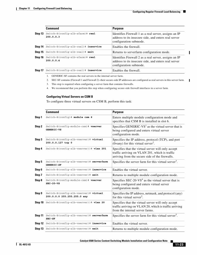
Configuring Virtual Servers on CSM B
To configure three virtual servers on CSM B, perform this task:
Step 13 Switch-B(config-slb-sfarm)# real 200.0.0.3
Identifies Firewall 1 as a real server, assigns an IP address to its insecure side, and enters real server configuration submode.
Step 14 Switch-B(config-slb-real)# inservice Enables the firewall.
Step 15 Switch-B(config-slb-real)# exit Returns to serverfarm configuration mode.
Step 16 Switch-B(config-slb-sfarm)# real 200.0.0.4
Identifies Firewall 2 as a real server, assigns an IP address to its insecure side, and enters real server configuration submode.
Step 17 Switch-B(config-slb-real)# inservice Enables the firewall.
1. GENERIC-SF contains the real servers in the internal server farm.
2. SEC-SF contains (Firewall 1 and Firewall 2)–their secure-side IP addresses are configured as real servers in this server farm.
3. This step is required when configuring a server farm that contains firewalls.
4. We recommend that you perform this step when configuring secure-side firewall interfaces in a server farm.
Command Purpose
Command Purpose
Step 1 Switch-B(config)# module csm 6 Enters multiple module configuration mode and specifies that CSM B is installed in slot 6.
Step 2 Switch-B(config-module-csm)# vserver GENERIC-VS
Specifies GENERIC-VS1 as the virtual server that is being configured and enters virtual server configuration mode.
Step 3 Switch-B(config-slb-vserver)# virtual 200.0.0.127 tcp 0
Specifies the IP address, protocol (TCP), and port (0=any) for this virtual server2.
Step 4 Switch-B(config-slb-vserver))# vlan 201 Specifies that the virtual server will only accept traffic arriving on VLAN 201, which is traffic arriving from the secure side of the firewalls.
Step 5 Switch-B(config-slb-vserver)# serverfarm GENERIC-SF
Specifies the server farm for this virtual server3.
Step 6 Switch-B(config-slb-vserver)# inservice Enables the virtual server.
Step 7 Switch-B(config-slb-vserver)# exit Returns to multiple module configuration mode.
Step 8 Switch-B(config-module-csm)# vserver SEC-20-VS
Specifies SEC-20-VS4 as the virtual server that is being configured and enters virtual server configuration mode.
Step 9 Switch-B(config-slb-vserver)# virtual 200.0.0.0 255.255.255.0 any
Specifies the IP address, netmask, and protocol (any) for this virtual server2.
Step 10 Switch-B(config-slb-vserver))# vlan 20 Specifies that the virtual server will only accept traffic arriving on VLAN 20, which is traffic arriving from the internal server farms.
Step 11 Switch-B(config-slb-vserver)# serverfarm SEC-SF
Specifies the server farm for this virtual server5.
Step 12 Switch-B(config-slb-vserver)# inservice Enables the virtual server.
Step 13 Switch-B(config-slb-vserver)# exit Returns to multiple module configuration mode.
11-23Catalyst 6500 Series Content Switching Module Installation and Configuration Note
OL-4612-03

Chapter 11 Configuring Firewall Load BalancingConfiguring Reverse-Sticky for Firewalls
Configuring Reverse-Sticky for FirewallsThe reverse-sticky feature creates a database of load-balancing decisions based on the client’s IP address. This feature overrides the load-balancing decision when a reverse-sticky entry is available in the database. If there is no reverse-sticky entry in the database, a load-balancing decision takes place, and the result is stored for future matching.
Understanding Reverse-Sticky for FirewallsReverse-sticky provides a way of inserting entries into a sticky database as if the connection came from the other direction. A virtual server with reverse-sticky places an entry into the specified database containing the inbound real server.
Note The inbound real server must be a real server within a server farm.
This entry is matched by a sticky command on a different virtual server. The other virtual server sends traffic to the client, based on this pregenerated entry.
The CSM stores reverse-sticky information as links from a source IP key to a real server. When the load balancer gets a new session on a virtual server with an assigned sticky database, it first checks the database for an existing entry. If a matching entry is found, the session is connected to the specified real server. Otherwise, a new entry is created linking the sticky key with the appropriate real server. Figure 11-8 shows how the reverse-sticky feature is used for firewalls.
Step 14 Switch-B(config-module-csm)# vserver SEC-200-VS
Specifies SEC-20-VS6 as the virtual server that is being configured and enters virtual server configuration mode.
Step 15 Switch-B(config-slb-vserver)# virtual 200.0.0.0 255.255.255.0 any
Specifies the IP address, netmask, and protocol (any) for this virtual server2.
Step 16 Switch-B(config-slb-vserver))# vlan 200 Specifies that the virtual server will only accept traffic arriving on VLAN 200, which is traffic arriving from the internal network.
Step 17 Switch-B(config-slb-vserver)# serverfarm SEC-SF
Specifies the server farm for this virtual server5.
Step 18 Switch-B(config-slb-vserver)# inservice Enables the virtual server.
1. GENERIC-VS allows traffic from the internal server farms and the internal network that is destined for the Internet to reach the secure side of the firewalls (through VLAN 101).
2. Clients reach the server farm represented by this virtual server through this address.
3. The server farm exists in the internal server farms network.
4. SEC-20-VS allows traffic from the Internet to reach the internal server farms (through VLAN 20).
5. The server farm contains firewalls rather than real servers.
6. SEC-200-VS allows traffic from the Internet to reach the internal network (through VLAN 20).
Command Purpose
11-24Catalyst 6500 Series Content Switching Module Installation and Configuration Note
OL-4612-03

Chapter 11 Configuring Firewall Load BalancingConfiguring Reverse-Sticky for Firewalls
Figure 11-8 Reverse-Sticky for Firewalls
As shown in Figure 11-8, the reverse-sticky process is as follows:
• A client connects to the CSM virtual server, VS1, through a load-balanced firewall. This load-balancing decision is made without interaction with the CSM.
• Server 1 creates a connection back to the original client. This connection matches virtual server VS2. VS2 uses the sticky information inserted by the original VS1 reverse-sticky. The connection now is forced to the same Firewall 1.
• A second client, coming in through a different firewall, connects to the same VS1. Reverse-sticky creates a new entry into database B for the second client, pointing to Firewall 2. VS1 also performs a normal sticky to Server 1.
• Server 1 creates a connection back to Client 2. The connection matches the connection in VS2. VS2 uses the sticky information inserted by the original VS1 reverse-sticky. This connection is used for the connection to Firewall 2.
• If the server had originated the first connection, the link back to the server would have been inserted by VS2, and a normal load-balancing decision would have generated a connection to one of the firewalls.
Note This configuration supports forward direction connections (client to server) using any balancing metric. However, the balancing metric to the firewalls from VS2 must match that of the unknown load balancer, or the unknown load balancer must stick new buddy connections in a similar manner if client responses to server initiated traffic are to be sent to the correct firewall.
Client12.1.1.1
Client12.1.1.2
Unknown loadbalancer Firewalls Sticky "B"
Catalyst 6500CSM Sticky "A" Servers
Server 112
.1.1
.112
.1.1
.2
12.1
.1.1
12.1
.1.2
Fo
rward
VS
2S
ticky insert A
DS
T
Fo
rward
VS
1S
ticky insert B
SR
C
Forward connection to VS1STICKY INSERT "B"
Forward connection to VS1STICKY INSERT "B"
Server connection decisionSTICKY "B"
LB to Server 1Match/Insert on "A"
Server initiatiedconnection #1 to VS2
Server connection decisionSTICKY "B"
LB to Server 1Match/Insert on "A"
Server initiatedconnection to VS2
7788
8
11-25Catalyst 6500 Series Content Switching Module Installation and Configuration Note
OL-4612-03

Chapter 11 Configuring Firewall Load BalancingConfiguring Stateful Firewall Connection Remapping
Configuring Reverse-Sticky for FirewallsTo configure IP reverse-sticky for firewall load balancing, perform this task:
Configuring Stateful Firewall Connection RemappingTo configure the firewall reassignment feature, you must have an MSFC image from Cisco IOS software Release 12.1(19)E.
To configure firewall reassignment, follow these steps:
Step 1 In the serverfarm submode for firewalls, configure the action:
Cat6k-2(config)# serverfarm FW-FARMfailaction reassign
Step 2 Assign a backup real server for each firewall if it failed (probe or ARP), with these commands:
Cat6k-2(config-slb-sfarm)# serverfarm FW-FARMCat6k-2(config-slb-sfarm)# real 1.1.1.1Cat6k(config-slb-module-real)# backup real 2.2.2.2Cat6k(config-slb-module-real)# inserviceCat6k-2(config-slb-sfarm)# real 2.2.2.2Cat6k(config-slb-module-real)# backup real 3.3.3.3Cat6k(config-slb-module-real)# inserviceCat6k-2(config-slb-sfarm)# real 3.3.3.3Cat6k(config-slb-module-real)# backup real 1.1.1.1Cat6k(config-slb-module-real)# inservice
Step 3 Configure the ICMP probe (through firewall) for this server farm.
Step 4 Configure the ICMP probes for the CSMs outside and inside the firewall.
Make sure that the backup real server is configured in the same order in both CSMs.
The inservice standby option assigned to a real server specifies that this server only receives connections if they are destined or load-balanced to the failed primary server. If you configure the real server designated as real 2.2.2.2 with inservice standby, then all connections would go to either of the real servers designated as real 1.1.1.1 or real 3.3.3.3. When real server real 1.1.1.1 failed, the real server designated as real 2.2.2.2 will be active in place of real server real 1.1.1.1.
Command Purpose
Step 1 SLB-Switch(config)# module csm slot Associates load-balancing commands to a specific CSM module and enters the CSM module configuration submode for the specified slot.
Step 2 SLB-Switch(config-module-csm)# vserver virtserver-name
Identifies a virtual server and enters the virtual server configuration submode.
Step 3 SLB-Switch(config-slb-vserver)# sticky duration [group group-id] [netmask ip-netmask] [source | destination | both]
Defines the portion of the IP information (source, destination, or both) that is used for the sticky entry key.
Step 4 SLB-Switch(config-slb-vserver)# reverse-sticky group-id
Ensures that the CSM maintains connections in the opposite direction back to the original source.
Step 5 SLB-Switch# show module csm slot sticky Displays the sticky database.
11-26Catalyst 6500 Series Content Switching Module Installation and Configuration Note
OL-4612-03