Configuring bluestars: multihop scatternet formation for ... · Configuring BlueStars: Multihop...
12
Configuring BlueStars: Multihop Scatternet Formation for Bluetooth Networks Chiara Petrioli, Member, IEEE, Stefano Basagni, Member, IEEE, and Imrich Chlamtac, Fellow, IEEE Abstract—This paper describes a new protocol for the establishment of multihop ad hoc networks based on Bluetooth devices. The protocol proceeds in three phases: device discovery, partitioning of the network into Bluetooth piconets, and interconnection of the piconets into a connected scatternet. The protocol has the following desirable properties: It is executed at each node with no prior knowledge of the network topology, thus being fully distributed. The selection of the Bluetooth masters is driven by the suitability of a node to be the “best fit” for serving as a master. The generated scatternet is a connected mesh with multiple paths between any pair of nodes, thus achieving robustness. Differently from existing solutions, no extra hardware is required to run the protocol at each node and there is no need for a designated node to start the scatternet formation process. Simulation results are provided which evaluate the impact of the Bluetooth device discovery phase on the performance of the protocol. Index Terms—Bluetooth technology, scatternet formation, ad hoc networks. æ 1 INTRODUCTION I T is widely anticipated that fourth-generation wireless systems will extensively rely on the unlicensed opera- tions provided by ad hoc communications [1]. Allowing spontaneous deployment and self-planning/management, ad hoc networking will play an important role in delivering all kinds of wireless services from the Internet to the very hands of the mobile user. The Bluetooth (BT) technology, as described in the Specifications of the Bluetooth System Version 1.1 [2], is expected to be one of the most promising enabling technology for ad hoc networks. Originally introduced as short-range cable replacement, the BT specifications define ways for which each BT device 1 can set up multiple connections with neighboring devices so that communica- tion can be established in a multihop fashion. In this sense, Bluetooth devices spread in a geographic area can provide the missing wireless extension to the various heterogeneous network infrastructures, allowing a more pervasive wireless Internet access. One of the fundamental problems that needs to be addressed to turn this vision into reality is the design of solutions for self-organizing Bluetooth devices into con- nected multihop ad hoc networks. According to the specifications, when two BT nodes that are into each other’s communication range want to set up a communication link, one of them must assume the role of master of the communication while the other becomes its slave. This simple “one-hop” network is called a piconet (Fig. 1) and may include several slaves, no more than seven of which can be actively communicating with the master at the same time. Given its star-like topology, in the following we will also refer to a piconet as a BlueStar. If a master has more than seven slaves, some slaves have to be “parked.” To communicate with a parked slave, a master has to “unpark” it, while possibly parking another slave. The specifications allow each node to assume multiple roles. A node can be a master in one piconet and a slave in one or more other piconets (Fig. 2) or a slave in multiple piconets (Fig. 3). Devices with multiple roles act as gateways to adjacent piconets, thus creating a multihop ad hoc network called a scatternet. The BT specifications describe methods for device discovery and for the participation of a node to multiple piconets. However, solutions for scatternet formation are not provided, thus leaving room for research in this area. A first broader classification of the solutions proposed so far in the literature distinguishes between scatternet formation protocols that require the radio vicinity of all nodes (single-hop topologies) and protocols that work in the more general multihop scenario. All the solutions are distributed in the sense that the protocols are executed at each node with the sole knowledge of its immediate neighbors (nodes in its transmission range). Solutions of the first kind are presented in [3], [4], and [5]. The solution proposed in [3] is based on a leader election process to collect topology information. Then, a centralized algorithm is run at the leader to assign the roles to the network nodes. In order to achieve desirable scatternet properties, the centralized scheme executed by the leader requires that the number of network nodes is 36. The scatternet formation protocols presented in [4] and [5] run over single-hop topologies with no limitations on the number of nodes. However, the resulting scatternet is a tree, which limits efficiency and robustness. IEEE TRANSACTIONS ON COMPUTERS, VOL. 52, NO. 6, JUNE 2003 779 . C. Petrioli is with the Dipartimento di Informatica, Universita`degli Studi di Roma “La Sapienza,” Rome, Italy.E-mail: [email protected]. . S. Basagni is with the Department of Electrical and Computer Engineering, Northeastern University, Boston, MA 02115. E-mail: [email protected]. . I. Chlamtac is with the Department of Computer Science, University of Texas at Dallas, PO Box 830688, EC 33, Richardson, TX 75083. E-mail: [email protected]. Manuscript received 5 Nov. 2001; revised 9 Aug. 2002; accepted 30 Oct. 2002. For information on obtaining reprints of this article, please send e-mail to: [email protected], and reference IEEECS Log Number 117662. 1. From now on, the terms node and device will be used interchangeably. 0018-9340/03/$17.00 ß 2003 IEEE Published by the IEEE Computer Society
Transcript of Configuring bluestars: multihop scatternet formation for ... · Configuring BlueStars: Multihop...
Configuring BlueStars: Multihop ScatternetFormation for Bluetooth Networks
Chiara Petrioli, Member, IEEE, Stefano Basagni, Member, IEEE, and Imrich Chlamtac, Fellow, IEEE
Abstract—This paper describes a new protocol for the establishment of multihop ad hoc networks based on Bluetooth devices. The
protocol proceeds in three phases: device discovery, partitioning of the network into Bluetooth piconets, and interconnection of the
piconets into a connected scatternet. The protocol has the following desirable properties: It is executed at each node with no prior
knowledge of the network topology, thus being fully distributed. The selection of the Bluetooth masters is driven by the suitability of a
node to be the “best fit” for serving as a master. The generated scatternet is a connected mesh with multiple paths between any pair of
nodes, thus achieving robustness. Differently from existing solutions, no extra hardware is required to run the protocol at each node
and there is no need for a designated node to start the scatternet formation process. Simulation results are provided which evaluate the
impact of the Bluetooth device discovery phase on the performance of the protocol.
Index Terms—Bluetooth technology, scatternet formation, ad hoc networks.
æ
1 INTRODUCTION
IT is widely anticipated that fourth-generation wirelesssystems will extensively rely on the unlicensed opera-
tions provided by ad hoc communications [1]. Allowingspontaneous deployment and self-planning/management,ad hoc networking will play an important role in deliveringall kinds of wireless services from the Internet to the veryhands of the mobile user.
The Bluetooth (BT) technology, as described in theSpecifications of the Bluetooth System Version 1.1 [2], isexpected to be one of the most promising enablingtechnology for ad hoc networks. Originally introduced asshort-range cable replacement, the BT specifications defineways for which each BT device1 can set up multipleconnections with neighboring devices so that communica-tion can be established in a multihop fashion. In this sense,Bluetooth devices spread in a geographic area can providethe missing wireless extension to the various heterogeneousnetwork infrastructures, allowing a more pervasive wirelessInternet access.
One of the fundamental problems that needs to beaddressed to turn this vision into reality is the design ofsolutions for self-organizing Bluetooth devices into con-nected multihop ad hoc networks.
According to the specifications, when two BT nodes thatare into each other’s communication range want to set up acommunication link, one of them must assume the role of
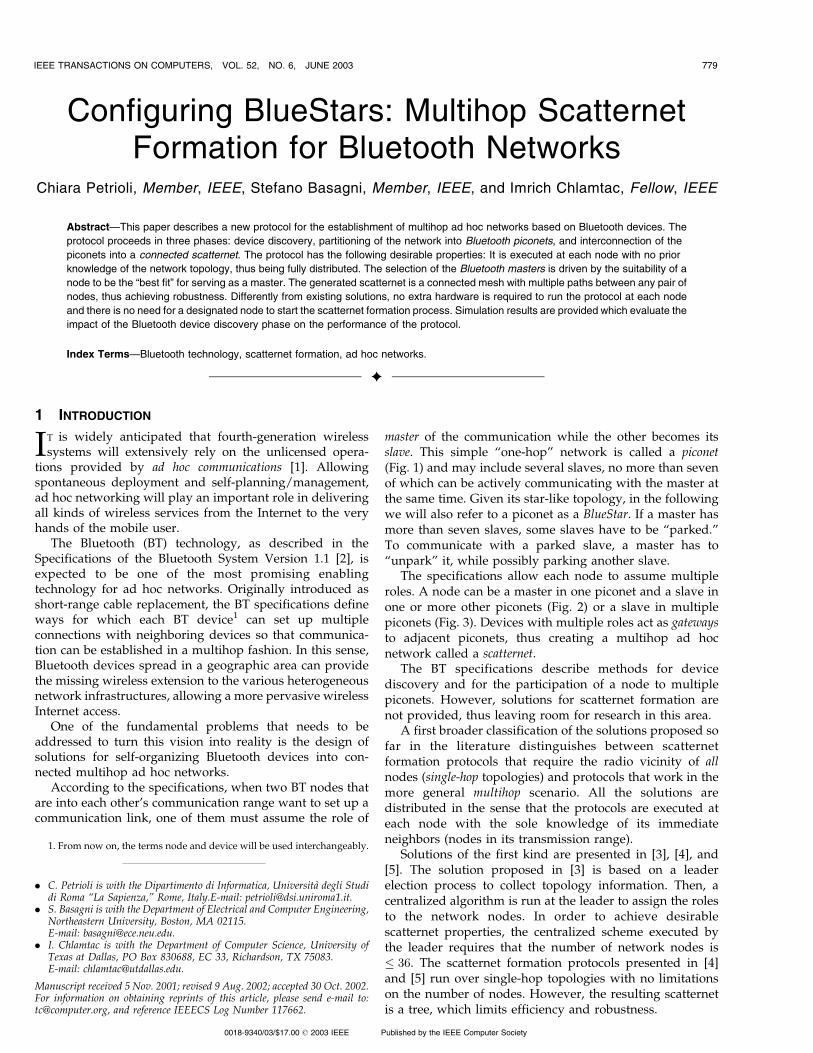
master of the communication while the other becomes itsslave. This simple “one-hop” network is called a piconet(Fig. 1) and may include several slaves, no more than sevenof which can be actively communicating with the master atthe same time. Given its star-like topology, in the followingwe will also refer to a piconet as a BlueStar. If a master hasmore than seven slaves, some slaves have to be “parked.”To communicate with a parked slave, a master has to“unpark” it, while possibly parking another slave.
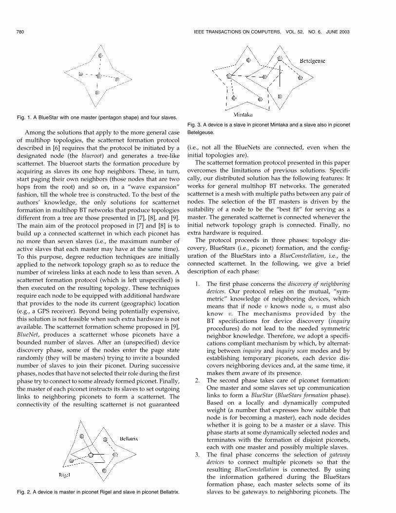
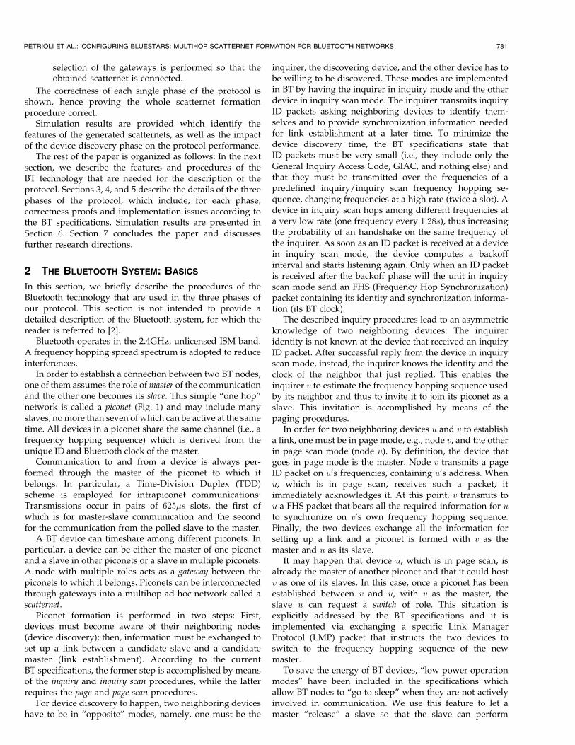
The specifications allow each node to assume multipleroles. A node can be a master in one piconet and a slave inone or more other piconets (Fig. 2) or a slave in multiplepiconets (Fig. 3). Devices with multiple roles act as gatewaysto adjacent piconets, thus creating a multihop ad hocnetwork called a scatternet.
The BT specifications describe methods for devicediscovery and for the participation of a node to multiplepiconets. However, solutions for scatternet formation arenot provided, thus leaving room for research in this area.
A first broader classification of the solutions proposed sofar in the literature distinguishes between scatternetformation protocols that require the radio vicinity of allnodes (single-hop topologies) and protocols that work in themore general multihop scenario. All the solutions aredistributed in the sense that the protocols are executed ateach node with the sole knowledge of its immediateneighbors (nodes in its transmission range).
Solutions of the first kind are presented in [3], [4], and[5]. The solution proposed in [3] is based on a leaderelection process to collect topology information. Then, acentralized algorithm is run at the leader to assign the rolesto the network nodes. In order to achieve desirablescatternet properties, the centralized scheme executed bythe leader requires that the number of network nodes is� 36. The scatternet formation protocols presented in [4]and [5] run over single-hop topologies with no limitationson the number of nodes. However, the resulting scatternetis a tree, which limits efficiency and robustness.
IEEE TRANSACTIONS ON COMPUTERS, VOL. 52, NO. 6, JUNE 2003 779
. C. Petrioli is with the Dipartimento di Informatica, Universita degli Studidi Roma “La Sapienza,” Rome, Italy.E-mail: [email protected].
. S. Basagni is with the Department of Electrical and Computer Engineering,Northeastern University, Boston, MA 02115.E-mail: [email protected].
. I. Chlamtac is with the Department of Computer Science, University ofTexas at Dallas, PO Box 830688, EC 33, Richardson, TX 75083.E-mail: [email protected].
Manuscript received 5 Nov. 2001; revised 9 Aug. 2002; accepted 30 Oct. 2002.For information on obtaining reprints of this article, please send e-mail to:[email protected], and reference IEEECS Log Number 117662.
1. From now on, the terms node and device will be used interchangeably.
0018-9340/03/$17.00 ß 2003 IEEE Published by the IEEE Computer Society
Among the solutions that apply to the more general case
of multihop topologies, the scatternet formation protocol
described in [6] requires that the protocol be initiated by a
designated node (the blueroot) and generates a tree-like
scatternet. The blueroot starts the formation procedure by
acquiring as slaves its one hop neighbors. These, in turn,
start paging their own neighbors (those nodes that are two
hops from the root) and so on, in a “wave expansion”
fashion, till the whole tree is constructed. To the best of the
authors’ knowledge, the only solutions for scatternet
formation in multihop BT networks that produce topologies
different from a tree are those presented in [7], [8], and [9].
The main aim of the protocol proposed in [7] and [8] is to
build up a connected scatternet in which each piconet has
no more than seven slaves (i.e., the maximum number of
active slaves that each master may have at the same time).
To this purpose, degree reduction techniques are initially
applied to the network topology graph so as to reduce the
number of wireless links at each node to less than seven. A
scatternet formation protocol (which is left unspecified) is
then executed on the resulting topology. These techniques
require each node to be equipped with additional hardware
that provides to the node its current (geographic) location
(e.g., a GPS receiver). Beyond being potentially expensive,
this solution is not feasible when such extra hardware is not
available. The scatternet formation scheme proposed in [9],
BlueNet, produces a scatternet whose piconets have a
bounded number of slaves. After an (unspecified) device
discovery phase, some of the nodes enter the page state
randomly (they will be masters) trying to invite a bounded
number of slaves to join their piconet. During successive
phases, nodes that have not selected their role during the first
phase try to connect to some already formed piconet. Finally,
the master of each piconet instructs its slaves to set outgoing
links to neighboring piconets to form a scatternet. The
connectivity of the resulting scatternet is not guaranteed
(i.e., not all the BlueNets are connected, even when the
initial topologies are).The scatternet formation protocol presented in this paper
overcomes the limitations of previous solutions. Specifi-
cally, our distributed solution has the following features: It
works for general multihop BT networks. The generated
scatternet is a mesh with multiple paths between any pair of
nodes. The selection of the BT masters is driven by the
suitability of a node to be the “best fit” for serving as a
master. The generated scatternet is connected whenever the
initial network topology graph is connected. Finally, no
extra hardware is required.The protocol proceeds in three phases: topology dis-
covery, BlueStars (i.e., piconet) formation, and the config-
uration of the BlueStars into a BlueConstellation, i.e., the
connected scatternet. In the following, we give a brief
description of each phase:
1. The first phase concerns the discovery of neighboringdevices. Our protocol relies on the mutual, “sym-metric” knowledge of neighboring devices, whichmeans that if node v knows node u, u must alsoknow v. The mechanisms provided by theBT specifications for device discovery (inquiryprocedures) do not lead to the needed symmetricneighbor knowledge. Therefore, we adopt a specifi-cations compliant mechanism by which, by alternat-ing between inquiry and inquiry scan modes and byestablishing temporary piconets, each device dis-covers neighboring devices and, at the same time, itmakes them aware of its presence.
2. The second phase takes care of piconet formation:One master and some slaves set up communicationlinks to form a BlueStar (BlueStars formation phase).Based on a locally and dynamically computedweight (a number that expresses how suitable thatnode is for becoming a master), each node decideswhether it is going to be a master or a slave. Thisphase starts at some dynamically selected nodes andterminates with the formation of disjoint piconets,each with one master and possibly multiple slaves.
3. The final phase concerns the selection of gatewaydevices to connect multiple piconets so that theresulting BlueConstellation is connected. By usingthe information gathered during the BlueStarsformation phase, each master selects some of itsslaves to be gateways to neighboring piconets. The
780 IEEE TRANSACTIONS ON COMPUTERS, VOL. 52, NO. 6, JUNE 2003
Fig. 1. A BlueStar with one master (pentagon shape) and four slaves.
Fig. 2. A device is master in piconet Rigel and slave in piconet Bellatrix.
Fig. 3. A device is a slave in piconet Mintaka and a slave also in piconet
Betelgeuse.
selection of the gateways is performed so that theobtained scatternet is connected.
The correctness of each single phase of the protocol isshown, hence proving the whole scatternet formationprocedure correct.
Simulation results are provided which identify thefeatures of the generated scatternets, as well as the impactof the device discovery phase on the protocol performance.
The rest of the paper is organized as follows: In the nextsection, we describe the features and procedures of theBT technology that are needed for the description of theprotocol. Sections 3, 4, and 5 describe the details of the threephases of the protocol, which include, for each phase,correctness proofs and implementation issues according tothe BT specifications. Simulation results are presented inSection 6. Section 7 concludes the paper and discussesfurther research directions.
2 THE BLUETOOTH SYSTEM: BASICS
In this section, we briefly describe the procedures of theBluetooth technology that are used in the three phases ofour protocol. This section is not intended to provide adetailed description of the Bluetooth system, for which thereader is referred to [2].
Bluetooth operates in the 2.4GHz, unlicensed ISM band.A frequency hopping spread spectrum is adopted to reduceinterferences.
In order to establish a connection between two BT nodes,one of them assumes the role of master of the communicationand the other one becomes its slave. This simple “one hop”network is called a piconet (Fig. 1) and may include manyslaves, no more than seven of which can be active at the sametime. All devices in a piconet share the same channel (i.e., afrequency hopping sequence) which is derived from theunique ID and Bluetooth clock of the master.
Communication to and from a device is always per-formed through the master of the piconet to which itbelongs. In particular, a Time-Division Duplex (TDD)scheme is employed for intrapiconet communications:Transmissions occur in pairs of 625�s slots, the first ofwhich is for master-slave communication and the secondfor the communication from the polled slave to the master.
A BT device can timeshare among different piconets. Inparticular, a device can be either the master of one piconetand a slave in other piconets or a slave in multiple piconets.A node with multiple roles acts as a gateway between thepiconets to which it belongs. Piconets can be interconnectedthrough gateways into a multihop ad hoc network called ascatternet.
Piconet formation is performed in two steps: First,devices must become aware of their neighboring nodes(device discovery); then, information must be exchanged toset up a link between a candidate slave and a candidatemaster (link establishment). According to the currentBT specifications, the former step is accomplished by meansof the inquiry and inquiry scan procedures, while the latterrequires the page and page scan procedures.
For device discovery to happen, two neighboring deviceshave to be in “opposite” modes, namely, one must be the
inquirer, the discovering device, and the other device has tobe willing to be discovered. These modes are implementedin BT by having the inquirer in inquiry mode and the otherdevice in inquiry scan mode. The inquirer transmits inquiryID packets asking neighboring devices to identify them-selves and to provide synchronization information neededfor link establishment at a later time. To minimize thedevice discovery time, the BT specifications state thatID packets must be very small (i.e., they include only theGeneral Inquiry Access Code, GIAC, and nothing else) andthat they must be transmitted over the frequencies of apredefined inquiry/inquiry scan frequency hopping se-quence, changing frequencies at a high rate (twice a slot). Adevice in inquiry scan hops among different frequencies ata very low rate (one frequency every 1:28s), thus increasingthe probability of an handshake on the same frequency ofthe inquirer. As soon as an ID packet is received at a devicein inquiry scan mode, the device computes a backoffinterval and starts listening again. Only when an ID packetis received after the backoff phase will the unit in inquiryscan mode send an FHS (Frequency Hop Synchronization)packet containing its identity and synchronization informa-tion (its BT clock).
The described inquiry procedures lead to an asymmetricknowledge of two neighboring devices: The inquireridentity is not known at the device that received an inquiryID packet. After successful reply from the device in inquiryscan mode, instead, the inquirer knows the identity and theclock of the neighbor that just replied. This enables theinquirer v to estimate the frequency hopping sequence usedby its neighbor and thus to invite it to join its piconet as aslave. This invitation is accomplished by means of thepaging procedures.
In order for two neighboring devices u and v to establisha link, one must be in page mode, e.g., node v, and the otherin page scan mode (node u). By definition, the device thatgoes in page mode is the master. Node v transmits a pageID packet on u’s frequencies, containing u’s address. Whenu, which is in page scan, receives such a packet, itimmediately acknowledges it. At this point, v transmits tou a FHS packet that bears all the required information for uto synchronize on v’s own frequency hopping sequence.Finally, the two devices exchange all the information forsetting up a link and a piconet is formed with v as themaster and u as its slave.
It may happen that device u, which is in page scan, isalready the master of another piconet and that it could hostv as one of its slaves. In this case, once a piconet has beenestablished between v and u, with v as the master, theslave u can request a switch of role. This situation isexplicitly addressed by the BT specifications and it isimplemented via exchanging a specific Link ManagerProtocol (LMP) packet that instructs the two devices toswitch to the frequency hopping sequence of the newmaster.
To save the energy of BT devices, “low power operationmodes” have been included in the specifications whichallow BT nodes to “go to sleep” when they are not activelyinvolved in communication. We use this feature to let amaster “release” a slave so that the slave can perform
PETRIOLI ET AL.: CONFIGURING BLUESTARS: MULTIHOP SCATTERNET FORMATION FOR BLUETOOTH NETWORKS 781
protocol related operations in another piconet. Among theseveral modes provided in the specifications for low poweroperations, in our protocol, we take advantage of the parkmode. A slave that has been put in park mode by its mastercannot be actively involved in communication with thatmaster. However, parked slaves periodically wake up inpredefined beacon slots to listen to their master commu-nication. Unparking of (possibly multiple) devices isachieved by transmitting an LMP unpark Protocol DataUnit (PDU) in the beacon slot. This packet carries the ID ofthe devices to be unparked and their new active slaveaddresses. Parked slaves can trigger an unpark LMP PDUby sending explicit requests during preallocated slots(access window). Similarly, active devices can ask to beparked (or they can be parked by their master) byexchanging an LMP park packet with their master.
3 SCATTERNET FORMATION I: TOPOLOGY
DISCOVERY
In this section, we describe how each pair of neighboringdevices obtain information about the ID and weight ofeach other by using the procedures of the inquiry andpage substates.
The inquiry procedures described in the BT specifica-tions indicate how a device in inquiry mode can trigger apeer device in inquiry scan mode to send its ID and thesynchronization information needed for link establishment(see Section 2). However, no indication is given on how toguarantee that neighboring devices are in opposite inquirymodes, which is the needed condition for them tocommunicate. Furthermore, the inquiry message broadcastby the source does not contain any information about thesource itself. Thus, once two neighboring devices completean inquiry handshake, only the source knows the identity ofthe device in inquiry scan mode, not vice versa.
To overcome these drawbacks and attain mutual knowl-edge of ID and weights, we use a mechanism similar to thatintroduced in [3]. Each device is allowed to alternatebetween inquiry mode and inquiry scan mode, remainingin each mode for a time selected randomly and uniformly ina predefined time range (details can be found in [10]). Theoperations while in each of the two modes are those asdescribed in the specifications. When two nodes in oppositeinquiry modes handshake, they set up a temporary piconetthat lasts only the time necessary to exchange their ID andweight (thus achieving the required mutual knowledge).
The following procedure describes the operations per-formed at each device v as it enters the topology discoveryphase of the protocol.
DISCOVERY(v)
1 Tdisc ‘td
2 while Tdisc > 0
3 do if RAND(0, 1) < 0.5
4 then INQUIRYMODE
5 COMPUTE(Tinq)
6 INQUIRYðminðTinq;TdiscÞÞ7 INQUIRYSCANMODE
8 COMPUTEðTscanÞ9 INQUIRYSCANðminðTscan;TdiscÞÞ
10 else INQUIRYSCANMODE
11 COMPUTEðTscanÞ12 INQUIRYSCANðminðTscan;TdiscÞ,13 INQUIRYMODE
14 COMPUTEðTinqÞ15 INQUIRYðminðTinq;TdiscÞ,16 EXIT
The generic device v that executes the discovery procedure,
sets a timer Tdisc to a predefined time length of the discovery
phase ‘td. This timer is decremented at each clock tick
(namely, Tdisc keeps track of the remaining time till the end
of this phase).
Device v then randomly enters either inquiry or
inquiry scan mode and computes the length of the
selected phase (Tinq or Tscan). While in a given mode,
device v performs the inquiry procedures as described by
the BT specifications. The procedures that implement the
inquiry mode (Procedure INQUIRY) or the inquiry scan
mode (Procedure INQUIRYSCAN) are executed for the
computed time (Tinq and Tscan, respectively), not to exceed
Tdisc. Upon completion of an inquiry (inquiry scan) phase,
if Tdisc > 0, a device switches to the inquiry scan (inquiry)
mode. As mentioned, to allow each pair of neighboring
devices to achieve a mutual knowledge of each others ID
and weight, our scheme requires that, whenever a device
in inquiry (inquiry scan) mode receives (sends) an
FHS packet, a temporary piconet is set up by means of
a page phase and devices exchange their ID and weight,
together with the synchronization information required
for further communication. As soon as this information
has been successfully communicated, the piconet is
disrupted.The effectiveness of the described mechanism in provid-
ing the needed mutual knowledge to pairs of neighboringdevices relies on the idea that, by alternating betweeninquiry and inquiry scan mode and randomly selecting thelength of each inquiry (inquiry scan) phase, we have highprobability that any pair of neighboring devices will be inopposite mode for a sufficiently long time, thus allowingthe devices to discover each other.
Simulation results presented in [10] evaluate the effec-tiveness of the presented mechanism for device discoveryand provide insights on parameter tuning.
3.1 Topology Discovery Correctness
As a result of the device discovery phase, each device v has
the list of the IDs, weights, and synchronization information
of all the devices it was able to discover within Tdisc. Only
statistical guarantees can be provided on a device being able
to become aware of all its neighbors. Given that all devices
enter the topology discovery phase in a given time interval
ðt0; t1Þ, t1 < Tdisc, the greater the value of Tdisc, the higher the
probability for a device to discover all its neighbors, the
longer the discovery phase duration.In the following, we prove the termination of the
topology discovery phase and that, whenever all packetsare successfully received, all devices have a symmetric view
782 IEEE TRANSACTIONS ON COMPUTERS, VOL. 52, NO. 6, JUNE 2003
of its neighbors.2 This symmetric knowledge of neighboringnodes is the basis for the correctness of the following phasesof our protocol.
Proposition 1. Each device v terminates the execution of thetopology discovery phase. If device v has discovered aneighbor u, it knows its ID and weight and so does u of v.
Proof. The proof of the first part of the claim is straightfor-ward as each device exits this phase after timer Tdisc hasexpired. The second part of the claim can be derivedfrom the protocol operations: Whenever a device dis-covers a neighbor, the two devices create a temporarypiconet. The two neighbors then exchange ID and weightand the piconet is torn down. The construction of thepiconet and the information exchanged during its brieflifetime guarantee the symmetric knowledge of thepiconet nodes. tu
4 SCATTERNET FORMATION II:BLUESTARS FORMATION
In this section, we describe a distributed protocol forgrouping the BT devices into piconets. Given that eachpiconet is formed by one master and a limited number ofslaves that form a star-like topology (Fig. 1), we call thisphase of the protocol the BlueStars formation phase.
Based on the information gathered in the previous phase,namely, the ID, the weight, and synchronization informa-tion of the discovered neighbors, each device performs theprotocol locally. The rule followed by each device is thefollowing: A device v decides whether it is going to be amaster or a slave depending on the decision made by theneighbors with bigger weight (v’s “bigger neighbors”). Inparticular, v becomes the slave of the first master among itsbigger neighbors that has paged it and invited it to join itspiconet. In case no bigger neighbors invited v, v itselfbecomes a master. Once a device has decided its role, itcommunicates it to all its (smaller) neighbors so that theycan also make their own decision.
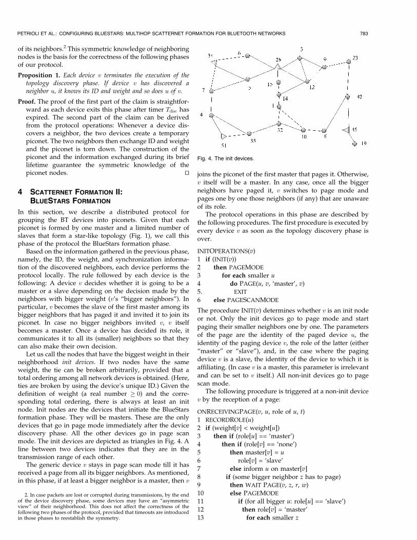
Let us call the nodes that have the biggest weight in theirneighborhood init devices. If two nodes have the sameweight, the tie can be broken arbitrarily, provided that atotal ordering among all network devices is obtained. (Here,ties are broken by using the device’s unique ID.) Given thedefinition of weight (a real number � 0) and the corre-sponding total ordering, there is always at least an initnode. Init nodes are the devices that initiate the BlueStarsformation phase. They will be masters. These are the onlydevices that go in page mode immediately after the devicediscovery phase. All the other devices go in page scanmode. The init devices are depicted as triangles in Fig. 4. Aline between two devices indicates that they are in thetransmission range of each other.
The generic device v stays in page scan mode till it hasreceived a page from all its bigger neighbors. As mentioned,in this phase, if at least a bigger neighbor is a master, then v
joins the piconet of the first master that pages it. Otherwise,v itself will be a master. In any case, once all the biggerneighbors have paged it, v switches to page mode andpages one by one those neighbors (if any) that are unawareof its role.
The protocol operations in this phase are described bythe following procedures. The first procedure is executed byevery device v as soon as the topology discovery phase isover.
INITOPERATIONS(v)
1 if (INIT(v))
2 then PAGEMODE
3 for each smaller u
4 do PAGE(u, v, ‘master’, v)
5. EXIT
6 else PAGESCANMODE
The procedure INIT(v) determines whether v is an init nodeor not. Only the init devices go to page mode and startpaging their smaller neighbors one by one. The parametersof the page are the identity of the paged device u, theidentity of the paging device v, the role of the latter (either“master” or “slave”), and, in the case where the pagingdevice v is a slave, the identity of the device to which it isaffiliating. (In case v is a master, this parameter is irrelevantand can be set to v itself.) All non-init devices go to pagescan mode.
The following procedure is triggered at a non-init devicev by the reception of a page:
ONRECEIVINGPAGE(v, u, role of u, t)1 RECORDROLE(u)
2 if (weight[v] < weight[u])
3 then if (role[u] == ‘master’)
4 then if (role[v] == ‘none’)
5 then master[v] = u
6 role[v] = ‘slave’
7 else inform u on master[v]
8 if (some bigger neighbor z has to page)9 then WAIT PAGE(v, z, r, w)
10 else PAGEMODE
11 if (for all bigger u: role[u] == ‘slave’)
12 then role[v] = ‘master’
13 for each smaller z
PETRIOLI ET AL.: CONFIGURING BLUESTARS: MULTIHOP SCATTERNET FORMATION FOR BLUETOOTH NETWORKS 783
2. In case packets are lost or corrupted during transmissions, by the endof the device discovery phase, some devices may have an “asymmetricview” of their neighborhood. This does not affect the correctness of thefollowing two phases of the protocol, provided that timeouts are introducedin those phases to reestablish the symmetry.
Fig. 4. The init devices.
14 do PAGE(z, v, ‘master’, v)15 for each bigger slave w
16 do PAGE(w, v, ‘master’, v)
17 EXIT
18 else for each slave neighbor z
19 do k = master[v]
20 PAGE(z, v, ‘slave’, k)
21 PAGESCANMODE
22 else if (some smaller neighbor z has to page)23 then WAIT PAGE(v, z, r, w)
24 else EXIT
The procedure of recording the role of a device u (line 1)includes all the information of synchronization, addressing,etc., that enable v to establish a communication with u at alater time, if needed. In addition, if node u is a slave, theidentity of u’s master is also recorded.
Upon receiving a page from a device u, device v startschecking if this is a page from a bigger neighbor or from asmaller one. (Pages from smaller neighbors are needed forgathering information used later in the gateway selectionprocedure.) In case the page is from a bigger neighbor u, vchecks if u is a master. If so, and v is not part of any piconetyet, it joins device u’s piconet. If, instead, device v hasalready joined a piconet, it informs device u about this, alsocommunicating the ID of its master. Device v then proceedsto check if all its bigger neighbors have paged it. If this isnot the case, it keeps waiting for another page (exiting theexecution of the procedure).
When successfully paged by all its bigger neighbors,device v knows whether it has already joined the piconet ofa bigger master or not. In the first case, device v is the slaveof the bigger master that paged it first. In the latter case,device v itself is going to be a master. In any case, device vgoes to page mode and communicates its decision first to allits smaller neighbors and then also to its bigger neighborsthat are slaves.
At this point, a master v exits the execution of this phaseof the protocol. If device v is a slave, it returns to page modeand waits for pages from all its smaller neighbors. Indeed,some of a slave’s smaller neighbors may not have decidedtheir role at the time they are paged by the bigger slave. Assoon as a device makes a decision on its role, it thereforepages its bigger neighbors and communicates whether it isa master or a slave, along with its master ID (if it is a slave).This exchange of information is necessary to implement thefollowing phase of gateway selection for obtaining aconnected scatternet (see Section 5).
Notice that the outermost else is executed only by a slavenode since, once it has paged all its neighbors, a master hasa complete knowledge of its neighbors’ role and of the ID oftheir masters and thus it can quit the execution of this phaseof the protocol.
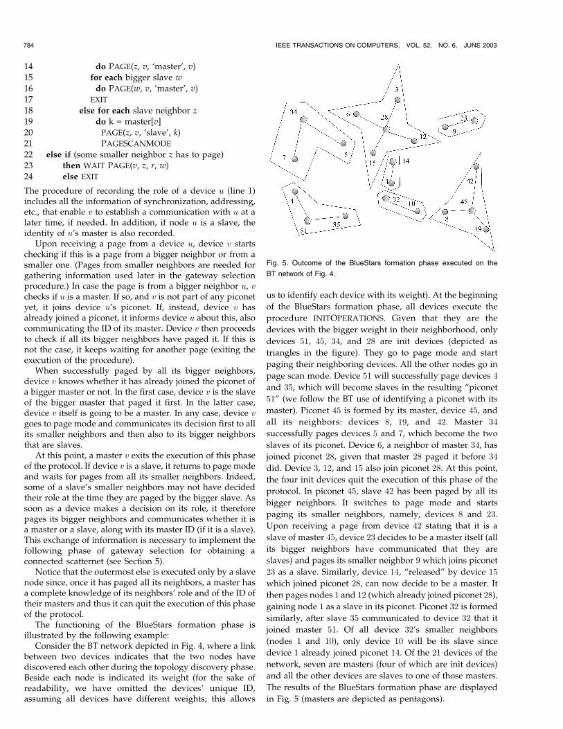
The functioning of the BlueStars formation phase isillustrated by the following example:
Consider the BT network depicted in Fig. 4, where a linkbetween two devices indicates that the two nodes havediscovered each other during the topology discovery phase.Beside each node is indicated its weight (for the sake ofreadability, we have omitted the devices’ unique ID,assuming all devices have different weights; this allows
us to identify each device with its weight). At the beginning
of the BlueStars formation phase, all devices execute the
procedure INITOPERATIONS. Given that they are the
devices with the bigger weight in their neighborhood, only
devices 51, 45, 34, and 28 are init devices (depicted as
triangles in the figure). They go to page mode and start
paging their neighboring devices. All the other nodes go in
page scan mode. Device 51 will successfully page devices 4
and 35, which will become slaves in the resulting “piconet
51” (we follow the BT use of identifying a piconet with its
master). Piconet 45 is formed by its master, device 45, and
all its neighbors: devices 8, 19, and 42. Master 34
successfully pages devices 5 and 7, which become the two
slaves of its piconet. Device 6, a neighbor of master 34, has
joined piconet 28, given that master 28 paged it before 34
did. Device 3, 12, and 15 also join piconet 28. At this point,
the four init devices quit the execution of this phase of the
protocol. In piconet 45, slave 42 has been paged by all its
bigger neighbors. It switches to page mode and starts
paging its smaller neighbors, namely, devices 8 and 23.
Upon receiving a page from device 42 stating that it is a
slave of master 45, device 23 decides to be a master itself (all
its bigger neighbors have communicated that they are
slaves) and pages its smaller neighbor 9 which joins piconet
23 as a slave. Similarly, device 14, “released” by device 15
which joined piconet 28, can now decide to be a master. It
then pages nodes 1 and 12 (which already joined piconet 28),
gaining node 1 as a slave in its piconet. Piconet 32 is formed
similarly, after slave 35 communicated to device 32 that it
joined master 51. Of all device 32’s smaller neighbors
(nodes 1 and 10), only device 10 will be its slave since
device 1 already joined piconet 14. Of the 21 devices of the
network, seven are masters (four of which are init devices)
and all the other devices are slaves to one of those masters.
The results of the BlueStars formation phase are displayed
in Fig. 5 (masters are depicted as pentagons).
784 IEEE TRANSACTIONS ON COMPUTERS, VOL. 52, NO. 6, JUNE 2003
Fig. 5. Outcome of the BlueStars formation phase executed on the
BT network of Fig. 4.
4.1 BlueStars Formation Correctness
All devices are always able to distinguish between a pagesent by a device in phase one (where paging is used to setup a temporary piconet to achieve symmetric topologyknowledge) and a page of the second phase based on theparameter role. In the topology discovery phase, theparameter role is always set to “none,” whereas, in theBlueStars formation phase it is always either “master” or“slave” since devices send pages only after having decidedabout their role.
This said, the correctness of the BlueStars formationphase, is based on the following facts:
1. Each device terminates the execution of this phase ofthe protocol.
2. Upon termination each device v:
a. Is either a master or a slave.b. Belongs to only one piconet.
We start by proving the following result.
Proposition 2. Each device v decides which role to assume (eithermaster or slave) and communicates it to its neighbors. Device vcommunicates its role only after all its bigger neighbors havecommunicated their role to it.
Proof. We assume that there are no transmission errors, i.e.,that all attempted pages are successful and lead to theexchange of all the information needed for the formationof a piconet.
Let B be the set of all Bluetooth devices, ðjBj ¼ nÞ, andlet I � B be the set of the init devices. We enumerate thedevices in B according to the following one-to-onecorrespondence big : B! f1; . . .ng, defined as follows:
bigðxÞ ¼ jIj ÿ ordIðxÞ þ 1 if x 2 I;nÿ ordBnIðxÞ þ 1 if x 2 B n I;
�where ordS : S ! f1; . . . jSjg is defined so that thatordSðxÞ ¼ i if x is the ith order statistics in the set Saccording to the devices’ weight (as customary, ties arebroken by using the devices’ unique ID) [11]. Function bigorders the devices in such a way that the init devicescome first, sorted in decreasing order with respect totheir weight, and all the other devices come after, sortedin decreasing order according to their weight.
We now proceed by induction on bigðxÞ ¼ k � n,x 2 B, i.e., the number of consecutive (with respect tobig) devices.
The induction base case is comprised of the initdevices, i.e., those devices i such that bigðiÞ � jIj. Sincethere is always at least an init device, the set I is neverempty. The proof of the base case is based on the code ofProcedure INITOPERATIONS: Having no bigger devices,an init node immediately decides its role, goes to pagemode, and communicates its role to its neighbors (whichare in page scan mode).
Let us now assume that all nodes x such thatbigðxÞ � h, h > jIj, have decided their role and havecommunicated it after all their bigger neighbors did.
Consider the device y such that bigðyÞ ¼ hþ 1. Bydefinition of big, all y’s bigger neighbors z are such thatbigðzÞ < bigðyÞ (bigger neighbors come first).
By inductive hypothesis, every such neighbor z hasdecided its role and, as stated by the code of ProcedureONRECEIVINGPAGE, it has paged each of its smallerneighbors (which include y) to communicate its role andit is in page scan mode. This implies that device y hasreceived a page from every bigger neighbor and thatonly one of the following cases holds: Either 1) all itsbigger neighbors are slaves or 2) there is at least a masterthat paged y. In case 1), device y decides to be a master,goes to page mode, and communicates its role to all itssmaller neighbors and to all its bigger neighbors that areslaves, as described in Procedure ONRECEIVINGPAGE. Incase 2), device y, affiliated with the master that paged itfirst (i.e., it decides to be a slave), goes to page mode andcommunicates to all the smaller neighbors and to all itsbigger neighbors that are slaves that it is a slave alongwith the ID of its master. The smaller devices are eitherin the topology discovery phase (which will be exited infinite time) or in page scan mode since they are notallowed to switch to page mode till every biggerneighbor pages them so that the role and master ID willbe successfully communicated. The bigger neighbors thatare slaves are in page scan mode by inductivehypothesis. tu
A useful corollary of Proposition 2 is stated by the
following result.
Corollary 1. Every slave receives information about the ID, role,
and the ID of the master of all its smaller neighbors.
We are finally able to state the correctness of the
BlueStars formation phase.
Proposition 3. Each device terminates the execution of the
BlueStars formation phase of the protocol having being
assigned either the role of master or the role of slave in one
single piconet.
Proof. Each master device terminates the execution of the
BlueStars formation phase as soon as it has made its
decision and it has paged all its neighbors about it
(Proposition 2). It is not possible for a master device to
reenter the execution of this phase of the protocol and to
assume another role.As soon as a slave has communicated its decision, it is
no longer able to execute the then branch of the “if(weight[v] < weight[u])” command (line 2 of ProcedureONRECEIVINGPAGE). This means that it cannot changeits role. Termination, in this case, derives from Proposi-tion 2 and Corollary 1. tu
Another useful property of the BlueStars formation
phase is stated by the following proposition.
Proposition 4. Upon exiting the execution of the BlueStars
formation phase, a device v knows the identity, the role, and, if
slaves, the ID of the master of all its neighbors.
Proof. Derives immediately from the code of the procedures
that implement this phase of the protocol and from the
previous propositions. tu
PETRIOLI ET AL.: CONFIGURING BLUESTARS: MULTIHOP SCATTERNET FORMATION FOR BLUETOOTH NETWORKS 785
4.2 Implementation According to the BluetoothTechnology
The protocol operations of this phase all rely on thestandard Bluetooth page procedures. However, the pageand page scan procedures used here assume the possibilityof exchanging additional information, such as the devicerole and, for slaves, the ID of their masters. This informationcannot be included in the FHS packet which is the packetexchanged in the standard page procedures.
Our proposal is to add an LMP protocol data unit (PDU),including fields to record the role of the sending device andthe ID of its master, to easily exchange the informationneeded for scatternet formation while possibly avoiding acomplete set up of the piconet.
Of course, whenever a slave joins a nontemporarypiconet, a complete piconet set up has to be performed,after which the slave is put in park mode to allow it toproceed with the protocol operation (e.g., performingpaging itself when needed).
5 SCATTERNET FORMATION III: CONFIGURING
BLUESTARS—THE BLUECONSTELLATION
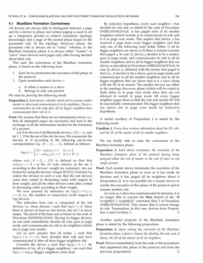
The purpose of the third phase of our protocol is tointerconnect neighboring BlueStars by selecting interpic-onet gateway devices so that the resulting scatternet, aBlueConstellation, is connected.3 The main tasks accom-plished by this phase of the protocol are thus gatewayselection and gateway interconnection.
We start by introducing some definitions.Two masters are said to be neighboring masters (mNeighbors,
for short) if there is either a two-hop path between them,with the intermediate node being a slave of one of them(gateway slave), or there is a three-hop path going throughtwo of their slaves (called intermediate gateways). Forinstance, in Fig. 4, masters 51 and 34 are mNeighbors sincethey can be interconnected via the two intermediategateways 4 and 7.
A master is said to be an init master, or simply an iMaster,if it has the biggest weight among all its mNeighbors.Therefore, the set of masters that results from the BlueStarsformation phase is partitioned into two sets, the iMastersand the non-iMasters devices. Referring again to Fig. 4, theiMasters are masters 51 and 45. The remaining 5 masters arenon-iMasters.
The connectivity of the scatternet is guaranteed by thefollowing result, first proven in [12].
Theorem 1 (Theorem 1 [12]). Given the piconets resulting fromthe BlueStars formation phase, a BlueConstellation (aconnected BT scatternet) is guaranteed to arise if each masterestablishes multihop connections to all its mNeighbors. Theseconnections are all needed to ensure that the resultingscatternet is connected in the sense that, if any of them ismissing, the scatternet may be not connected.
Theorem 1 provides us with a criterion for selectinggateways that ensures the connectivity of the resultingscatternet: For every two masters, their slaves in the two
and three-hop paths between them will be gateways. If
there is more than one interconnection path between the
same two masters (as between piconets 28 and 23 in Fig. 4),
they might decide to keep only one gateway slave or one
pair of intermediate gateways between them or to maintain
multiple interconnections. (In the following, we assume the
former rule for interconnecting masters.)Gateway selection is performed locally at each master
based on the information gathered by the end of the BlueStars
formation, namely, 1) the ID and weight of all its own slaves,
2) the ID, weight, and the ID of the masters of its slaves’ one-
hop neighbors (gathered via its own slaves), and 3) the ID,
weight, and the ID of the masters of its neighboring slaves that
did not join its piconet. Pairs of neighboring masters adopt
consistent rules of selection. For example, in the case of two-
hop mNeighbors, the biggest gateway slave is chosen. In the
case of three-hop mNeighbors, the pairs of intermediate
gateways the sum of whose weight is the biggest.
5.1 The BlueConstellation: Establishment of aConnected Scatternet
Once the gateway selection has been performed, we are
finally able to establish all the connections and the needed
new piconets for obtaining a BlueConstellation, i.e., a
connected scatternet.This phase is initiated by all masters v by executing the
following procedure.
MINITOPERATIONS(v)
1 if (MINIT(v))
2 then for each gateway u
3 do INSTRUCTPAGE(u)4 PAGEMODE
5 for each selected gateway u: master[u] != v
6 do PAGE(u, v, ‘master’, v)
7 EXIT
8 else for each gateway to bigger mNeighbors u
9 do INSTRUCTPAGESCAN(u)
10 if (BIGGERMNSLAVES(v))
11 then PAGESCANMODE
12 for each gateway u to bigger mNeighbors t
13 do WAIT PAGE(v, u, ‘slave’, t)
14 for each gateway u to smaller mNeighbors
15 do INSTRUCTPAGE(u)
16 if (SMALLERMNSLAVES(v))
17 then pAGEMODE
18 for each gateway u to smaller mNeighbors
19 do PAGE(u, v, ‘master’, v)
Every master v starts by checking (via Procedure MINIT(v),
line 1) whether it is an iMaster or not. If it is an iMaster,
then, via Procedure INSTRUCTPAGE(u), it instructs each of
its gateway slaves and intermediate gateways u to go into
page mode and to page (if any):
. The mNeighbors for which u has been selected asgateway slave. In this case, as soon as u has becomethe master of an mNeighbor t, they perform a switchof roles (Section 2) so that u also becomes a slave int’s piconet. In this case, no new piconet is formed
786 IEEE TRANSACTIONS ON COMPUTERS, VOL. 52, NO. 6, JUNE 2003
3. In the following, we assume that there is the physical possibility ofobtaining a connected scatternet.
and the slave between v and t is now a slave in boththeir piconets, as desirable.
. Its peer intermediate gateways selected to intercon-nect v with its three-hop mNeighbors t. In this case,u becomes also a master of a piconet whose slave isalso a slave to t, i.e., a new piconet is created to bethe trait d’union between the two masters.
The iMaster v itself can then go into page mode (line 4 in
the previous procedure) to recruit into its piconet some ofthose neighboring nodes (if any) that joined some other
piconets so that these nodes can be the gateways to theiroriginal masters.
Notice that, given the knowledge that every master hasabout its “mNeighborhood,” an iMaster v instructs each of its
gateways u about exactly who to page and the resulting new
piconet composition. If, for instance, u is gateway to multiplepiconets, v knows exactly to which of the neighboring
piconets u is going to be also a slave and if it has to be masterof a piconet that can have, in turn, multiple slaves.
A node v that is not an iMaster uses ProcedureINSTRUCTPAGESCAN to instruct all its slaves u that are
gateways to bigger mNeighbors to go to page scan mode
and to wait for the specified nodes to page them (line 9).Then, v checks if there are gateway slaves of bigger
mNeighbors to whom it has to interconnect (the check is
performed via the Boolean function BIGGERMNSLAVES). Ifthis is the case, v waits to be paged by them. After the links
to bigger mNeighbors have been so established, v starts toset up links to smaller mNeighbors. To this purpose, it acts
as if it were an iMaster.When the gateways of a non-iMaster device v have set up
proper connections toward bigger mNeighbors, they will go
into page mode and page those of v’s two-hop mNeighborsand those of the slaves of v’s three-hop mNeighbors with
which they have been requested by v to establish aconnection.
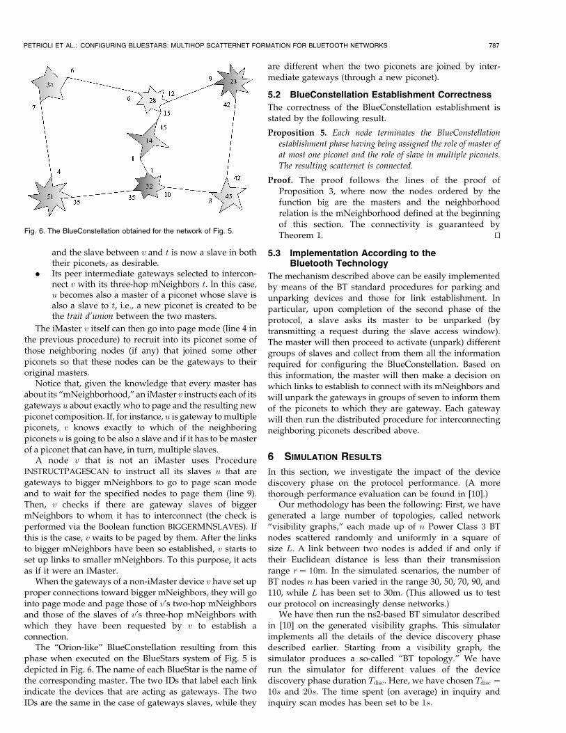
The “Orion-like” BlueConstellation resulting from thisphase when executed on the BlueStars system of Fig. 5 is
depicted in Fig. 6. The name of each BlueStar is the name of
the corresponding master. The two IDs that label each linkindicate the devices that are acting as gateways. The two
IDs are the same in the case of gateways slaves, while they
are different when the two piconets are joined by inter-mediate gateways (through a new piconet).
5.2 BlueConstellation Establishment Correctness
The correctness of the BlueConstellation establishment isstated by the following result.
Proposition 5. Each node terminates the BlueConstellation
establishment phase having being assigned the role of master of
at most one piconet and the role of slave in multiple piconets.
The resulting scatternet is connected.
Proof. The proof follows the lines of the proof ofProposition 3, where now the nodes ordered by thefunction big are the masters and the neighborhoodrelation is the mNeighborhood defined at the beginning
of this section. The connectivity is guaranteed byTheorem 1. tu
5.3 Implementation According to theBluetooth Technology
The mechanism described above can be easily implementedby means of the BT standard procedures for parking andunparking devices and those for link establishment. In
particular, upon completion of the second phase of theprotocol, a slave asks its master to be unparked (bytransmitting a request during the slave access window).The master will then proceed to activate (unpark) different
groups of slaves and collect from them all the informationrequired for configuring the BlueConstellation. Based onthis information, the master will then make a decision onwhich links to establish to connect with its mNeighbors andwill unpark the gateways in groups of seven to inform them
of the piconets to which they are gateway. Each gatewaywill then run the distributed procedure for interconnectingneighboring piconets described above.
6 SIMULATION RESULTS
In this section, we investigate the impact of the devicediscovery phase on the protocol performance. (A morethorough performance evaluation can be found in [10].)
Our methodology has been the following: First, we havegenerated a large number of topologies, called network
“visibility graphs,” each made up of n Power Class 3 BTnodes scattered randomly and uniformly in a square ofsize L. A link between two nodes is added if and only iftheir Euclidean distance is less than their transmissionrange r ¼ 10m. In the simulated scenarios, the number of
BT nodes n has been varied in the range 30, 50, 70, 90, and110, while L has been set to 30m. (This allowed us to testour protocol on increasingly dense networks.)
We have then run the ns2-based BT simulator describedin [10] on the generated visibility graphs. This simulator
implements all the details of the device discovery phasedescribed earlier. Starting from a visibility graph, thesimulator produces a so-called “BT topology.” We haverun the simulator for different values of the device
discovery phase duration Tdisc. Here, we have chosen Tdisc ¼10s and 20s. The time spent (on average) in inquiry andinquiry scan modes has been set to be 1s.
PETRIOLI ET AL.: CONFIGURING BLUESTARS: MULTIHOP SCATTERNET FORMATION FOR BLUETOOTH NETWORKS 787
Fig. 6. The BlueConstellation obtained for the network of Fig. 5.
Finally, we have run the second and third phases of theprotocol on the obtained BT topologies and evaluated theeffects of the different choices of Tdisc on the averagenumber of piconets and on the number of slaves per piconetof the obtained scatternets. For this part of the protocolevaluation, we have used a simulator of BT-based ad hocnetworks implemented in C++.
All experiments have been performed on a number ofconnected topologies that allow us to achieve a confidencelevel of 95 percent and a precision within 5 percent.
The impact of the device discovery phase is alreadyevident from Table 1, which shows a significant decrease ofthe network nodal degree (average number of neighbors foreach node) of the BT topologies over the visibility graphs.As Tdisc increases, the degree increases to account for theincreased number of neighbors discovered.
As the network density of the visibility graph increases,it gets more and more time consuming to discover allneighbors. However, a small number of neighbors need tobe discovered for obtaining connected BT topologies. This isshown in Table 2: Both for Tdisc ¼ 10s and 20s, all theBT topologies are connected in case of moderately dense todense visibility graphs (n � 50 nodes). For n ¼ 30, whichcorresponds to a sparse scenario where less than 95 percentof the generated visibility graphs are connected, thediscovery of a very high percentage of neighbors is requiredto maintain connectivity. However, the neighbors discov-ered in 10s are already enough to produce connectedBT topologies 95 percent of the time.
Despite the comparable percentage of connectedBT topologies at the two different values of Tdisc, thedifferent number of links in the BT topologies stillnoticeably affects the protocol performance. We haveconsidered three metrics, namely, the average number ofpiconets generated by our protocol, the average number ofslaves per piconet, and the 99th percentile of the number ofslaves per piconet.
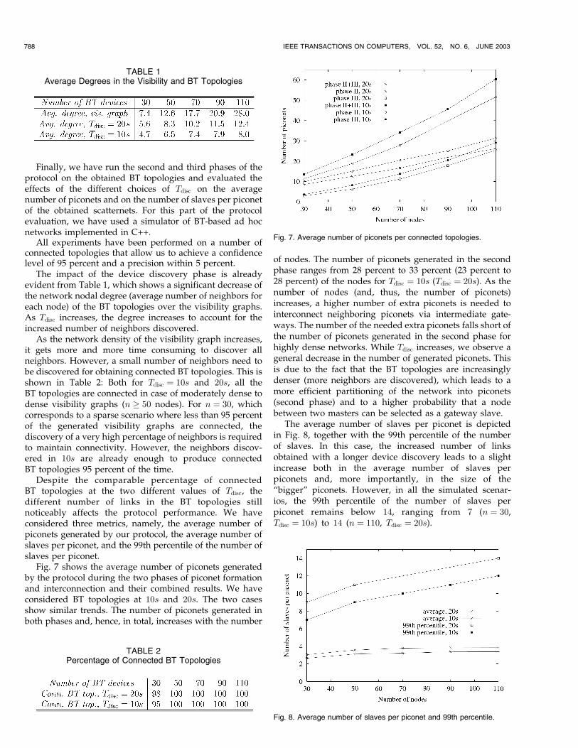
Fig. 7 shows the average number of piconets generatedby the protocol during the two phases of piconet formationand interconnection and their combined results. We haveconsidered BT topologies at 10s and 20s. The two casesshow similar trends. The number of piconets generated inboth phases and, hence, in total, increases with the number
of nodes. The number of piconets generated in the secondphase ranges from 28 percent to 33 percent (23 percent to28 percent) of the nodes for Tdisc ¼ 10s (Tdisc ¼ 20s). As thenumber of nodes (and, thus, the number of piconets)increases, a higher number of extra piconets is needed tointerconnect neighboring piconets via intermediate gate-ways. The number of the needed extra piconets falls short ofthe number of piconets generated in the second phase forhighly dense networks. While Tdisc increases, we observe ageneral decrease in the number of generated piconets. Thisis due to the fact that the BT topologies are increasinglydenser (more neighbors are discovered), which leads to amore efficient partitioning of the network into piconets(second phase) and to a higher probability that a nodebetween two masters can be selected as a gateway slave.
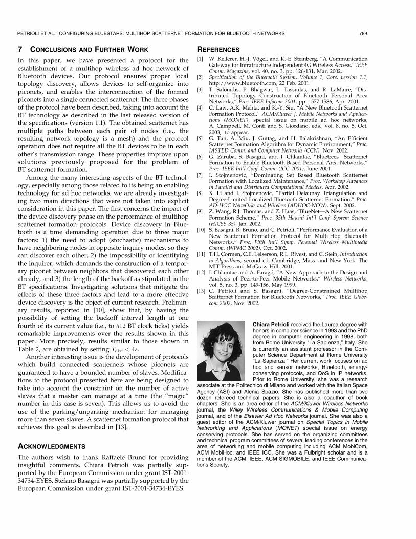
The average number of slaves per piconet is depictedin Fig. 8, together with the 99th percentile of the numberof slaves. In this case, the increased number of linksobtained with a longer device discovery leads to a slightincrease both in the average number of slaves perpiconets and, more importantly, in the size of the“bigger” piconets. However, in all the simulated scenar-ios, the 99th percentile of the number of slaves perpiconet remains below 14, ranging from 7 (n ¼ 30,Tdisc ¼ 10s) to 14 (n ¼ 110, Tdisc ¼ 20s).
788 IEEE TRANSACTIONS ON COMPUTERS, VOL. 52, NO. 6, JUNE 2003
TABLE 1Average Degrees in the Visibility and BT Topologies
TABLE 2Percentage of Connected BT Topologies
Fig. 7. Average number of piconets per connected topologies.
Fig. 8. Average number of slaves per piconet and 99th percentile.
7 CONCLUSIONS AND FURTHER WORK
In this paper, we have presented a protocol for theestablishment of a multihop wireless ad hoc network ofBluetooth devices. Our protocol ensures proper localtopology discovery, allows devices to self-organize intopiconets, and enables the interconnection of the formedpiconets into a single connected scatternet. The three phasesof the protocol have been described, taking into account theBT technology as described in the last released version ofthe specifications (version 1.1). The obtained scatternet hasmultiple paths between each pair of nodes (i.e., theresulting network topology is a mesh) and the protocoloperation does not require all the BT devices to be in eachother’s transmission range. These properties improve uponsolutions previously proposed for the problem ofBT scatternet formation.
Among the many interesting aspects of the BT technol-ogy, especially among those related to its being an enablingtechnology for ad hoc networks, we are already investigat-ing two main directions that were not taken into explicitconsideration in this paper. The first concerns the impact ofthe device discovery phase on the performance of multihopscatternet formation protocols. Device discovery in Blue-tooth is a time demanding operation due to three majorfactors: 1) the need to adopt (stochastic) mechanisms tohave neighboring nodes in opposite inquiry modes, so theycan discover each other, 2) the impossibility of identifyingthe inquirer, which demands the construction of a tempor-ary piconet between neighbors that discovered each otheralready, and 3) the length of the backoff as stipulated in theBT specifications. Investigating solutions that mitigate theeffects of these three factors and lead to a more effectivedevice discovery is the object of current research. Prelimin-ary results, reported in [10], show that, by having thepossibility of setting the backoff interval length at onefourth of its current value (i.e., to 512 BT clock ticks) yieldsremarkable improvements over the results shown in thispaper. More precisely, results similar to those shown inTable 2, are obtained by setting Tdisc < 4s.
Another interesting issue is the development of protocolswhich build connected scatternets whose piconets areguaranteed to have a bounded number of slaves. Modifica-tions to the protocol presented here are being designed totake into account the constraint on the number of activeslaves that a master can manage at a time (the “magic”number in this case is seven). This allows us to avoid theuse of the parking/unparking mechanism for managingmore than seven slaves. A scatternet formation protocol thatachieves this goal is described in [13].
ACKNOWLEDGMENTS
The authors wish to thank Raffaele Bruno for providinginsightful comments. Chiara Petrioli was partially sup-ported by the European Commission under grant IST-2001-34734-EYES. Stefano Basagni was partially supported by theEuropean Commission under grant IST-2001-34734-EYES.
REFERENCES
[1] W. Kellerer, H.-J. Vogel, and K.-E. Steinberg, “A CommunicationGateway for Infratructure Independent 4G Wireless Access,” IEEEComm. Magazine, vol. 40, no. 3, pp. 126-131, Mar. 2002.
[2] Specification of the Bluetooth System, Volume 1, Core, version 1.1,http://www.bluetooth.com, 22 Feb. 2001.
[3] T. Salonidis, P. Bhagwat, L. Tassiulas, and R. LaMaire, “Dis-tributed Topology Construction of Bluetooth Personal AreaNetworks,” Proc. IEEE Infocom 2001, pp. 1577-1586, Apr. 2001.
[4] C. Law, A.K. Mehta, and K.-Y. Siu, “A New Bluetooth ScatternetFormation Protocol,” ACM/Kluwer J. Mobile Networks and Applica-tions (MONET), special issue on mobile ad hoc networks,A. Campbell, M. Conti and S. Giordano, eds., vol. 8, no. 5, Oct.2003, to appear.
[5] G. Tan, A. Miu, J. Guttag, and H. Balakrishnan, “An EfficientScatternet Formation Algorithm for Dynamic Environment,” Proc.IASTED Comm. and Computer Networks (CCN), Nov. 2002.
[6] G. Zaruba, S. Basagni, and I. Chlamtac, “Bluetrees—ScatternetFormation to Enable Bluetooth-Based Personal Area Networks,”Proc. IEEE Int’l Conf. Comm. (ICC 2001), June 2001.
[7] I. Stojmenovic, “Dominating Set Based Bluetooth ScatternetFormation with Localized Maintenance,” Proc. Workshop Advancesin Parallel and Distributed Computational Models, Apr. 2002.
[8] X. Li and I. Stojmenovic, “Partial Delaunay Triangulation andDegree-Limited Localized Bluetooth Scatternet Formation,” Proc.AD-HOC NetwOrks and Wireless (ADHOC-NOW), Sept. 2002.
[9] Z. Wang, R.J. Thomas, and Z. Haas, “BlueNet—A New ScatternetFormation Scheme,” Proc. 35th Hawaii Int’l Conf. System Science(HICSS-35), Jan. 2002.
[10] S. Basagni, R. Bruno, and C. Petrioli, “Performance Evaluation of aNew Scatternet Formation Protocol for Multi-Hop BluetoothNetworks,” Proc. Fifth Int’l Symp. Personal Wireless MultimediaComm. (WPMC 2002), Oct. 2002.
[11] T.H. Cormen, C.E. Leiserson, R.L. Rivest, and C. Stein, Introductionto Algorithms, second ed. Cambridge, Mass. and New York: TheMIT Press and McGraw-Hill, 2001.
[12] I. Chlamtac and A. Farago, “A New Approach to the Design andAnalysis of Peer-to-Peer Mobile Networks,” Wireless Networks,vol. 5, no. 3, pp. 149-156, May 1999.
[13] C. Petrioli and S. Basagni, “Degree-Constrained MultihopScatternet Formation for Bluetooth Networks,” Proc. IEEE Globe-com 2002, Nov. 2002.
Chiara Petrioli received the Laurea degree withhonors in computer science in 1993 and the PhDdegree in computer engineering in 1998, bothfrom Rome University “La Sapienza,” Italy. Sheis currently an assistant professor in the Com-puter Science Department at Rome University“La Sapienza.” Her current work focuses on adhoc and sensor networks, Bluetooth, energy-conserving protocols, and QoS in IP networks.Prior to Rome University, she was a research
associate at the Politecnico di Milano and worked with the Italian SpaceAgency (ASI) and Alenia Spazio. She has published more than twodozen refereed technical papers. She is also a coauthor of bookchapters. She is an area editor of the ACM/Kluwer Wireless Networksjournal, the Wiley Wireless Communications & Mobile Computingjournal, and of the Elsevier Ad Hoc Networks journal. She was also aguest editor of the ACM/Kluwer journal on Special Topics in MobileNetworking and Applications (MONET) special issue on energyconserving protocols. She has served on the organizing committeesand technical program committees of several leading conferences in thearea of networking and mobile computing including ACM MobiCom,ACM MobiHoc, and IEEE ICC. She was a Fulbright scholar and is amember of the ACM, IEEE, ACM SIGMOBILE, and IEEE Communica-tions Society.
PETRIOLI ET AL.: CONFIGURING BLUESTARS: MULTIHOP SCATTERNET FORMATION FOR BLUETOOTH NETWORKS 789
Stefano Basagni received the PhD degree inelectrical engineering from the University ofTexas at Dallas (December 2001) and the PhDdegree in computer science from the Universityof Milano, Italy (May 1998). He received the BScdegree in computer science from the Universityof Pisa, Italy, in 1991. Since Winter 2002, he hasbeen a member of the faculty of the Departmentof Electrical and Computer Engineering atNortheastern University, Boston. From August2000 to January 2002, he was a professor of
computer science in the Department of Computer Science of the ErikJonsson School of Engineering and Computer Science, The Universityof Texas at Dallas. His current research interests concern research andimplementation aspects of mobile networks and wireless communica-tions systems, Bluetooth and sensor networking, definition andperformance evaluation of network protocols, and theoretical andpractical aspects of distributed algorithms. He has published more thantwo dozen referred technical papers. He is also a coauthor of bookchapters. He served as a guest editor of the special issue of the ACM/Kluwer journal on Special Topics in Mobile Networking and Applications(MONET) on multipoint communication in wireless mobile networks aswell as as a guest editor of the special issue on mobile ad hoc networksof the Wiley Interscience’s Wireless Communications & Mobile Net-works journal, for which he serves on the editorial board. He also servedand serves on technical program committees, including the ACM/SIGMOBILE MobiCom TPC, and ACM/SIGMOBILE MobiHoc TPC,IEEE Globecom, and IEEE ICC. He is a member of the ACM (includingthe ACM SIGMOBILE) and of the IEEE (Computer and CommunicationSocieties).
Imrich Chlamtac received the PhD degree incomputer science from the University of Minne-sota. Since 1997, he has been the DistinguishedChair in Telecommunications at the University ofTexas at Dallas. He also holds the titles of theSackler Professor at Tel Aviv University, Israel,The Bruno Kessler Honorary Professor at theUniversity of Trento, Italy, where he is currentlyon sabbatical, and University Professor at theTechnical University of Budapest, Hungary. He
is a fellow of the IEEE and ACM, a Fulbright Scholar, and an IEEEDistinguished Lecturer. He is the winner of the 2001 ACM SIGMOBILEannual award and the IEEE ComSoc TCPC 2002 award for contribu-tions to wireless and mobile networks, and of multiple best paper awardson wireless and optical networks. He has published close to 300 papersin refereed journals and conferences and is the coauthor of the firsttextbook on Local Area Networks (Lexington Books, 1981, 1982, 1984)and of Mobile and Wireless Networks Protocols and Services (JohnWiley & Sons, 2000)—an IEEE Network Magazine 2000 Editor’s Choice.He serves as the founding editor-in-chief of the ACM/URSI/KluwerWireless Networks (WINET), the ACM/Kluwer Mobile Networks andApplications (MONET) journals, and the SPIE/Kluwer Optical Networks(ONM) magazine.
. For more information on this or any computing topic, please visitour Digital Library at http://computer.org/publications/dlib.
790 IEEE TRANSACTIONS ON COMPUTERS, VOL. 52, NO. 6, JUNE 2003