Configuring and Managing SMC 7 - Oracle · Configuring and Managing SMC Version 7.0 ... TABLE A-3...
134
Submit comments about this document to [email protected]. StorageTek Enterprise Library Software Configuring and Managing SMC Version 7.0 Part Number: E28330-05 July 2014
Transcript of Configuring and Managing SMC 7 - Oracle · Configuring and Managing SMC Version 7.0 ... TABLE A-3...

Submit comments about this document to [email protected].
StorageTek Enterprise Library Software
Configuring and Managing SMC
Version 7.0
Part Number: E28330-05 July 2014

2 Configuring and Managing SMC 7.0 July 2014
Configuring and Managing SMC 7.0
E28330-05
Oracle welcomes your comments and suggestions for improving this book. Contact us at [email protected]. Please include the title, part number, issue date, and revision.
Copyright © 2012, 2014, Oracle and/or its affiliates. All rights reserved.
This software and related documentation are provided under a license agreement containing restrictions on use and disclosure and are protected by intellectual property laws. Except as expressly permitted in your license agreement or allowed by law, you may not use, copy, reproduce, translate, broadcast, modify, license, transmit, distribute, exhibit, perform, publish, or display any part, in any form, or by any means. Reverse engineering, disassembly, or decompilation of this software, unless required by law for interoperability, is prohibited.
The information contained herein is subject to change without notice and is not warranted to be error-free. If you find any errors, please report them to us in writing.
If this is software or related software documentation that is delivered to the U.S. Government or anyone licensing it on behalf of the U.S. Government, the following notice is applicable:
U.S. GOVERNMENT RIGHTS Programs, software, databases, and related documentation and technical data delivered to U.S. Government customers are "commercial computer software" or "commercial technical data" pursuant to the applicable Federal Acquisition Regulation and agency-specific supplemental regulations. As such, the use, duplication, disclosure, modification, and adaptation shall be subject to the restrictions and license terms set forth in the applicable Government contract, and, to the extent applicable by the terms of the Government contract, the additional rights set forth in FAR 52.227-19, Commercial Computer Software License (December 2007). Oracle USA, Inc., 500 Oracle Parkway, Redwood City, CA 94065.
This software or hardware is developed for general use in a variety of information management applications. It is not developed or intended for use in any inherently dangerous applications, including applications which may create a risk of personal injury. If you use this software or hardware in dangerous applications, then you shall be responsible to take all appropriate fail-safe, backup, redundancy, and other measures to ensure the safe use. Oracle Corporation and its affiliates disclaim any liability for any damages caused by use of this software or hardware in dangerous applications.
Oracle is a registered trademark of Oracle Corporation and/or its affiliates. Oracle and Java are registered trademarks of Oracle and/or its affiliates. Other names may be trademarks of their respective owners.
AMD, Opteron, the AMD logo, and the AMD Opteron logo are trademarks or registered trademarks of Advanced Micro Devices. Intel and Intel Xeon are trademarks or registered trademarks of Intel Corporation. All SPARC trademarks are used under license and are trademarks or registered trademarks of SPARC International, Inc. UNIX is a registered trademark licensed through X/Open Company, Ltd.
This software or hardware and documentation may provide access to or information on content, products, and services from third parties. Oracle Corporation and its affiliates are not responsible for and expressly disclaim all warranties of any kind with respect to third-party content, products, and services. Oracle Corporation and its affiliates will not be responsible for any loss, costs, or damages incurred due to your access to or use of third-party content, products, or services.
Revision 05 3
Contents
Preface 13
1. Introduction 21
2. Starting the SMC 23
Overview 23
Creating the SMC START Procedure 25
SMCPARMS and SMCCMDS Data Sets 26
SMCLOG Data Set 27
SYSTCPD Data Set 27
SMC EXEC Statement 28
Executing the SMC START Procedure 31
MVS START Command 31
3. SMC and StorageTek TapePlex Management 33
Overview 33
SMC and the Library Control Server 33
Defining TapePlexes for SMC 34
Using the SMC Client-Server Feature 34
Security Administration Considerations for Communication 34
Defining Server Paths 35
Client Communication Monitor Subtask 35
Using the SMC HTTP Server Component 36
SMC Configuration Scenarios 37
Scenario 1: Single TapePlex with SMC and HSC on the Same Host 38
Scenario 2: Single TapePlex using the SMC Client/Server Feature 39
4 Configuring and Managing SMC 7.0 • July 2014 Revision 05
Scenario 3: Two TapePlexes Accessed by a Single SMC 41
Client/Server Drive Address Mapping 43
SMC Drive Type Information Synchronization 44
Specifying Drive Type Information Using SMC UNITAttr Commands 44
SMC TapePlex Selection 47
4. Policy 49
Overview 49
The SMC POLicy Command 50
SMC Policy and Esoteric Preferencing 51
SMC Policy at IDAX 52
SMC Esoteric Substitution at IDAX 53
SMC Policy and the TAPEREQ Control Statement 54
Example 56
SMC DFSMS Processing 57
Enabling/Disabling the SMC DFSMS Interface 57
Tailoring the SMC DFSMS Interface 57
Defining StorageTek DFSMS ACS Routines to Specify MGMTCLAS 58
Invoking ACS Routines 58
DFSMS Automatic Class Selection (ACS) Routine Environment for SMC 60
MGMTCLAS Routine Considerations 61
5. Allocation 65
Overview 65
Drive Exclusion 67
Drive Exclusion - Specific Volumes 68
Drive Exclusion - Scratch Volumes 70
Affinity Separation 73
Affinity Head-Of-Chain 73
User Policy Influence on Affinity Separation 73
Drive Prioritization 74
Deferring Mounts 75
SMC Allocation Exceptions 75
SMC Allocation Processing - JES2 Operating System Hooks 76

Revision 05 Contents 5
SSI55 IDAX (Interpreter/Dynamic Allocation Exit) 76
SSI24 Common Allocation 76
SSI78 Tape Allocation 77
SMC Allocation Processing - JES3 Considerations 78
SMC Allocation - JES3 Not Managing Drives 78
SMC Allocation - JES3 Managing Drives 78
SSI55 IDAX (Interpreter/Dynamic Allocation Exit) 78
JES3 Converter/Interpreter (C/I) 79
SSI23 JES3 Dynamic Allocation 79
JES3 Main Device Scheduler (MDS) 79
SSI24 Common Allocation 79
Esoteric Unit Name Replacement in JES3 80
Suppressing Fetch Messages in JES3 82
Drive Prioritization in JES3 83
JES3 Initialization Parameter Considerations 83
JES3 DEVICE Initialization Statements 84
JES3 SETNAME Initialization Statements 85
JES3 HWSNAME Initialization Statements 87
Esoteric Preferencing Considerations 90
Device Preferencing Considerations 90
ZEROSCR Considerations 90
SMC Normal Operations 91
JES3 Constraints 92
6. Message Handling 95
Overview 95
User Directed Message Handling 95
Message Handling Policies 96
MVS Policies 96
SMC Policies 96
Tape Management System Support 97
SMC Swap Processing 98
HSC Mount-Related Messages 99
Managing HSC Mounts from the SMC Client 99

6 Configuring and Managing SMC 7.0 • July 2014 Revision 05
7. Recovery Procedures 101
Overview 101
SMC Recovery Procedures (JES2) 101
Inactive SMC - Active TapePlex 102
Active SMC - Inactive TapePlex 102
Automating Mount Requests for Inactive TapePlexes 103
Lost MVS Mount Requests for Active TapePlexes 103
SMC Recovery Procedures (JES3) 104
Inactive SMC - Active TapePlex Subsystem 104
Active SMC - Inactive TapePlex 105
Inactive JES3 on a Local Processor 105
Inactive JES3 on a Global Processor 105
Automating Mount Requests for Inactive TapePlexes 106
Lost JES3 Mount Requests for Active TapePlexes 106
Lost MVS Mount Requests for Active TapePlexes 106
A. Intercepted Messages 107
IBM Operating System Messages 107
JES3 Messages 109
Tape Management System Messages 109
CA-1 Messages 109
CONTROL-M/TAPE (formerly CONTROL-T) Messages 110
DFSMSrmm Messages 111
B. SMC Interaction with Other Software 113
Automated Operations 113
CA-MIA Tape Sharing 113
CA1-RTS Real Time Stacking 113
CA-Vtape 114
Fault Analyzer for z/OS 115
MVS Security Packages 115
Open Type J 116
SAMS: DISK (DMS) 116
Glossary 117

Revision 05 Contents 7
Index 1

8 Configuring and Managing SMC 7.0 • July 2014 Revision 05

Revision 05 9
Figures
FIGURE 2-1 Sample SMC START Procedure 25
FIGURE 2-2 SMC EXEC Statement syntax 28
FIGURE 2-3 MVS START Command syntax 31
FIGURE 3-1 Single TapePlex with SMC and HSC on the Same Host 38
FIGURE 3-2 Single TapePlex using the SMC Client/Server Feature 39
FIGURE 3-3 Two TapePlexes Accessed by a Single SMC 41
FIGURE 4-1 Sample SMCCMDS Data Set 50
FIGURE 4-2 Creating Management Class Routines 61
FIGURE 5-1 Volume Locations for the Pass-thru Example 92

10 Configuring and Managing SMC 7.0 • July 2014 Revision 05

Revision 05 11
Tables
TABLE 3-1 SMC Client/Server Drive Address Mapping Scenarios 43
TABLE 5-1 Drive Exclusion Levels (Specific Request) 68
TABLE 5-2 Drive Exclusion Levels (Scratch Request) 70
TABLE 5-3 3490 Drive List 80
TABLE 5-4 Sample Configuration 83
TABLE A-1 Intercepted Operating System Messages 108
TABLE A-2 Tape Management System Messages - CA-1 109
TABLE A-3 CONTROL-M/TAPE Messages 110
TABLE A-4 Tape Management System Messages - DFSMSrmm 111

12 Configuring and Managing SMC 7.0 • July 2014 Revision 05

Revision 05 13
Preface
This publication describes how to configure and manage Oracle’s StorageTek Storage Management Component (SMC), part of Oracle’s StorageTek Enterprise Library Software (ELS). It is intended for storage administrators, system programmers and operators responsible for configuring and maintaining SMC.
To perform the tasks described in this publication, you should already understand the following:
■ z/OS operating system■ JES2 or JES3■ Enterprise Library Software (ELS)
Oracle’s StorageTek Enterprise Library Software (ELS) is a solution consisting of the following base software:
■ Oracle’s StorageTek Storage Management Component (SMC) (includes the product formerly known as StorageTek HTTP Server)
■ Oracle’s StorageTek Host Software Component (HSC)
■ Oracle’s StorageTek Virtual Tape Control Software (VTCS)
■ Oracle’s StorageTek Concurrent Disaster Recovery Test (CDRT)
Additionally, the following software is provided with the ELS package:
■ Oracle’s StorageTek Library Content Manager (LCM). LCM includes an enhanced version of the product formerly known as Offsite Vault Feature.
■ Oracle’s StorageTek Client System Component for MVS Environments (MVS/CSC)
■ Oracle’s StorageTek LibraryStation
Access to Oracle SupportOracle customers have access to electronic support through My Oracle Support:
http://www.oracle.com/support/contact.html
http://www.oracle.com/accessibility/support.html (for hearing impaired)

14 Configuring and Managing SMC 7.0 • July 2014 Revision 05
Related Documentation
StorageTek Enterprise Library Software (ELS)■ Introducing ELS ■ Installing ELS■ ELS Command, Control Statement, and Utility Reference■ ELS Syntax Quick Reference■ ELS Messages and Codes ■ ELS Programming Reference ■ ELS Legacy Interfaces Reference ■ Configuring HSC and VTCS ■ Managing HSC and VTCS ■ ELS Disaster Recovery and Offsite Data Management Guide
StorageTek Library Content Manager (LCM)■ LCM User’s Guide ■ LCM Messages and Codes ■ LCM Quick Reference
StorageTek Client System Component for MVS Environments (MVS/CSC)■ MVS/CSC Configuration Guide ■ MVS/CSC Messages and Codes Guide ■ MVS/CSC Operator’s Guide ■ MVS/CSC Syntax Quick Reference ■ MVS/CSC System Programmer’s Guide
StorageTek LibraryStation■ LibraryStation Configuration and Administration Guide ■ LibraryStation Syntax Quick Reference

Revision 05 Preface 15
Conventions for Reader Usability
TypographicSome JCL examples in this guide include italic type. Italic type is used to indicate a variable. You must substitute an actual value for these variables.
The use of mixed upper and lower case characters for commands, control statements, and parameters indicates that lower case letters may be omitted to form abbreviations. For example, you may simply enter POL when executing the POLicy command.
Syntax Flow DiagramsSyntax flow diagramming conventions include the following:
Flow LinesSyntax diagrams consist of a horizontal base line, horizontal and vertical branch lines, and the text for a command, control statement, macro, or utility. Diagrams are read left to right, and top to bottom. Arrows indicate flow and direction.
Single Required ChoiceBranch lines (without repeat arrows) indicate that a single choice must be made. If one of the items to choose from is positioned on the baseline of the diagram, one item must be selected.
COMMAND/MACRO/UTILITY Item 1Item 2Item 3
Item 1Item 2Item 3

16 Configuring and Managing SMC 7.0 • July 2014 Revision 05
Single Optional ChoiceIf the first item is positioned on the line below the baseline, one item may be optionally selected.
DefaultsDefault values and parameters appear above the baseline.
Some keyword parameters provide a choice of values in a stack. When the stack contains a default value, the keyword and the value choices are placed below the base line to indicate that they are optional, and the default value appears above the keyword line.
Repeat SymbolA repeat symbol indicates that more than one choice can be made or that a single choice can be made more than once. The following example indicates that a comma is required as the repeat delimiter.
Item 1Item 2Item 3
Default
KeywordValue3
Default ValueValue2
,variable

Revision 05 Preface 17
Keywords
All command keywords are shown in all upper case or in mixed case. When commands are not case sensitive, mixed case implies that the lowercase letters may be omitted to form an abbreviation.
Variables
Italic type is used to indicate a variable.
Alternatives
A bar ( | ) is used to separate alternative parameter values.
Optional
Brackets [ ] are used to indicate that a command parameter is optional.
Delimiters
If a comma (,), a semicolon (;), or other delimiter is shown with an element of the syntax diagram, it must be entered as part of the statement.
Ranges
An inclusive range is indicated by a pair of elements of the same length and data type, joined by a dash. The first element must be strictly less than the second element.
A hexadecimal range consists of a pair of hexadecimal numbers (for example, 0A2-0AD, or 000-0FC).
A decimal range consists of a pair of decimal numbers (i.e., 1-9, or 010-094). Leading zeros are not required. The decimal portion is referred to as an incremental range. The character positions of the incremental portion of both range elements must match, and the non incremental characters of the first element must be identical to those of the second element.
A numeric VOLSER range (vol-range) consists of a pair of VOLSER elements containing a decimal numeric portion of 1 to 6 digits (for example, ABC012-ABC025, or X123CB-X277CB). The decimal portion is referred to as an incremental range. The following additional restrictions apply:
■ The character positions of the incremental portion of both range elements must match.
■ The non incremental characters of the first element must be identical to those of the second element.
■ You cannot increment two portions of a range element. If 111AAA is the first element, you cannot specify 112AAB for the second element.

18 Configuring and Managing SMC 7.0 • July 2014 Revision 05
■ If a VOLSER range contains more than one decimal portion, any portion is valid as the incremental range. For example:
An alphabetic VOLSER range (vol-range) consists of a pair of VOLSER elements containing an incremental portion of 1 to 6 characters (for example, 000AAA-000ZZZ, or 9AAA55-9ZZZ55). This portion is referred to as an incremental range. The following additional restrictions apply:
■ The character positions of the incremental portion of both range elements must match.
■ The non incremental characters of the first element must be identical to those of the second element.
■ You cannot increment two portions of a range element. If 111AAA is the first element, you cannot specify 112AAB for the second element.
■ The alphabetic portion of the VOLSER range is defined as being from character A to Z. To increment multi-character sequences, each character increments to Z. For instance, ACZ is part of the AAA-AMM range. Examples are:
A00B00 the largest range that can be specified is A00B00 through A99B99.
A0B0CC the largest range that can be specified is A0B0CC through A9B9CC.
000XXX the largest range that can be specified is 000XXX through 999XXX.
A00A0-A99A0 increments VOLSERs A00A0 through A09A0, then A10A0 through A99A0.
9AA9A-9ZZ9A increments VOLSERs 9AA9A through 9AZ9A, then 9BA9A through 9ZZ9A.
111AAA-111ZZZ increments VOLSERs 111AAA through 111AAZ, then 111ABA through 111ZZZ
999AM8-999CM8 increments VOLSERs 999AM8 through 999AZ8, then 999BA8 through 999CM8
A3BZZ9-A3CDE9 increments VOLSERs A3BZZ9 through A3CAA9, then A3CAB9 through A3CDE9
AAAAAA-AAACCC increments VOLSERs AAAAAA through AAAAAZ, then AAAABA through AAACCC
CCCNNN-DDDNNN increments VOLSERs CCCNNN through CCCNNZ, then CCCNOA through DDDNNN *
* Caution: This is a very large range.

Revision 05 Preface 19
The number of volumes in an alphabetic VOLSER range depends on the number of elements in the incrementing portion of the VOLSER range. For an A to Z range in each character position, the number of volumes can be calculated by 26 to the power of the number of positions that are being incremented.
Lists
A list consists of one or more elements. If more than one element is specified, the elements must be separated by a comma or a blank space, and the entire list must be enclosed in parentheses.
Blanks
Keyword parameters and values may be separated by any number of blanks.
Control StatementsThe standard syntax conventions for control statements are as follows:
■ The only valid control statement information area is from column 1 to column 72. Columns 73-80 are ignored.
■ Parameters may be separated by one or more blanks or a comma.
■ A value is associated with a parameter by an equal (=) sign or by enclosing the value in parentheses, and concatenating it immediately after the parameter.
■ Case (upper or lower) is ignored in actual control statements.
■ Continuations are supported by including a plus (+) sign at the end of the line to be continued. A control statement is terminated if the statement is not continued.
■ /* and */ can be used to enclose comments in the job stream. Comments can be continued over multiple lines, but cannot be nested.
PARMLIB members must include a /*...*/ comment as the first control statement. Otherwise, the old format is assumed. Comments in the old format must begin with an asterisk (*) in column 1.
For definition data sets (e.g., VOLATTRs, UNITATTRs and TAPEREQs), comments must be in the new format (/*...*/).
■ Asterisk (*) comments are not allowed.
■ A /*...*/ comment in the first line is not required.
■ The maximum length for a control statement is 1024 characters.
A-Z 261 26
AA-ZZ 262 676
AAA-ZZZ 263 17,576
AAAA-ZZZZ 264 456,976
AAAAA-ZZZZZ 265 11,881,376
AAAAAA-ZZZZZZ 266 308,915,776

20 Configuring and Managing SMC 7.0 • July 2014 Revision 05

Revision 05 21
CHAPTER
1
Introduction
Storage Management Component (SMC) is the interface between IBM’s z/OS operating system and Oracle’s StorageTek automated library control systems, HSC and MVS/CSC.
SMC resides on every MVS host that accesses StorageTek real and virtual tape hardware. It operates on both JES2 and JES3 systems and is a required ELS component.
SMC primary functions include:
■ Influencing tape allocation according to hardware requirements and customer policies to ensure that appropriate tape drives are selected
■ Intercepting tape management, and operating system mount, dismount, and swap messages and translating them in order to request the required tape hardware functions from the appropriate ELS automated library control system
■ Coordinating requests among multiple StorageTek TapePlexes
A TapePlex is a single StorageTek hardware configuration, normally represented by a single HSC Control Data Set (CDS). A TapePlex may contain multiple Automated Cartridge Systems (ACSs) and Virtual Tape Storage Subsystems (VTSSs).
SMC may communicate with any number of TapePlexes, using cross address space facilities to communicate with HSC or MVS/CSC running on the same host, and TCP/IP to communicate with HSC systems executing on other hosts.
Note – ■ MVS/CSC 7.0 is not compatible with StorageTek LibraryStation. In an MVS-only
environment, you must use SMC and its HTTP server component to provide communication between MVS hosts. See Chapter 3, “SMC and StorageTek TapePlex Management” for more information.
■ For the purposes of this publication, HSC refers to the MVS implementation of HSC. The VM implementation of HSC is not supported by SMC.

22 Configuring and Managing SMC 7.0 • July 2014 Revision 05

Revision 05 23
CHAPTER
2
Starting the SMC
OverviewSMC manages all interfaces with MVS for allocation and message handling, and therefore must be started as a task on every MVS host where tape processing occurs.
SMC calls on HSC and MVS/CSC for volume and drive information. Therefore, HSC or MVS/CSC can be active on the same host as the SMC, or a local SMC can interact with an HSC operating on a remote host if the SMC HTTP server is also enabled on that remote host.
Oracle recommends that you start HSC and SMC in the following order:
1. Start HSC.
2. Immediately start SMC, as HSC initialization begins.
This is recommended for the following reasons:
■ TapePlexes and associated HSC/VTCS servers are defined in the SMCCMDS data set. During initialization, SMC attempts to establish a communication binding with one server for each TapePlex by contacting individual HSC/VTCS servers in order as defined in the SMCCMDS data set. SMC binds to the first active server encountered for each TapePlex during this process. For each TapePlex with no active servers, SMC displays persistent message SMC0260 for each server defined for that TapePlex. SMC removes these messages when a server becomes active and SMC automatically binds to it. To avoid TapePlex communication binding delays at SMC startup:
■ Ensure hosts referenced by SMC SERVER statements are IPLed and TCP/IP is fully initialized for communications on these hosts before starting SMC.
■ For hosts referenced by SMC SERVER statements, issue the HTTP START command as part of the SMC startup parameters for those hosts, in SMCPARMS or SMCCMDS.
■ For each TapePlex, start HSC/VTCS and SMC on at least one host referenced by an SMC SERVER statement for that TapePlex.
■ If your configuration includes VTCS with a VLE system, VTCS uses SMC communication services to communicate with VLE. If you start SMC immediately after HSC initialization begins, you can ensure that these services are available to VTCS when it attempts to communicate with the VLE.

Overview
24 Configuring and Managing SMC 7.0 • July 2014 Revision 05
Implementing all of these steps will allow SMC startup processing to bind with each TapePlex as quickly as possible.
To start SMC, you must create and execute the SMC START procedure. These tasks are described in this chapter.
Note – ■ Refer to the publication Installing ELS for information about SMC installation and
post-installation tasks.
■ The SMC HTTP server component is enabled using the SMC HTTP command. Refer to the ELS Command, Control Statement, and Utility Reference for more information about this command.

Creating the SMC START Procedure
Revision 05 Chapter 2 Starting the SMC 25
Creating the SMC START ProcedureThe SMC START procedure specifies SMC startup parameter settings. Create this procedure in the procedure library of the host system.
The MVS START command executes this catalogued procedure, thus activating the SMC with the specified parameter settings.
The following figure illustrates a sample SMC START procedure, which includes EXEC, STEPLIB, SMCPARMS, SMCCMDS, SMCLOG, and SYSTCPD DD statements:
FIGURE 2-1 Sample SMC START Procedure
The first four characters of yourprocname specify the SMC subsystem name (unless the SSYS startup parameter is specified). The recommended value is SMCx, where x is any valid jobname character.
//yourprocname PROC PRM=’WARM’//stepname EXEC PGM=SMCBINT,REGION=4M,TIME=1440,// PARM=’&PRM’//*//STEPLIB DD DISP=SHR,DSN=your.els.exitlib// DD DISP=SHR,DSN=your.els.sea700.sealink//*//* The following dataset is optional//*//SMCPARMS DD DISP=SHR,DSN=parmlib_name(parm_member_name)//*//* The following dataset is optional but recommended//*//SMCCMDS DD DISP=SHR,DSN=cmdlib_name(cmd_member_name)//*//* The following dataset is optional//*//SMCLOG DD DSN=log.file.name,UNIT=unit,RECFM=FB,// SPACE=(CYL,(primary-qty,secondary-qty)),// DISP=(NEW,CATLG,CATLG)//*//SYSTCPD DD DSN=ddd.eee.fff(anyname) /* Optional TCPIP parms) */

Creating the SMC START Procedure
26 Configuring and Managing SMC 7.0 • July 2014 Revision 05
SMCPARMS and SMCCMDS Data SetsThe SMCPARMS and SMCCMDS DD statements are optional. SMC operator commands specified in these data sets are automatically processed at startup.
■ The SMCCMDS data set specifies user-configured settings that can be changed while the SMC is active. Issue the READ command from the console to reprocess the SMCCMDS data set at any time.
■ The SMCPARMS data set specifies user-configured items that cannot be changed while the SMC is active. SMCPARMS cannot be reprocessed using the READ command.
Refer to the ELS Command, Control Statement, and Utility Reference for information about SMC commands that may be specified in either of these data sets. It is recommended that you include only those commands required to be in the SMCPARMS data set (e.g. CMDDEF and USERMSG) in SMCPARMS. Place all remaining startup parameters in SMCCMDS.
Review the following commands or control statements to determine whether they should be included in your SMCCMDS data set:
■ ALLOCDef■ DRIVemap■ HTtp■ MOUNTDef■ POLicy■ READ■ RESYNChronize■ SERVer■ TAPEPlex■ TCPip■ TREQDef■ UEXit■ UNITAttr
Note – ■ Use of the POLicy command requires that TAPEPlex and SERVer commands be
processed before POLicy commands (which must be processed before TAPEREQ control statements).
■ TIME=1440 must be coded to ensure that the SMC does not time out and terminate.
Creating the SMC START Procedure
Revision 05 Chapter 2 Starting the SMC 27
SMCLOG Data Set The SMCLOG DD statement is optional, and defines the output data set for SMC communication and command logging. The SMCLOG DD is required only when the SMC LOG START command is entered, and is written to only when the SMCLOG TYPE command is entered to select the specific types of events the SMC will log.
Note – The SMC logging facility is intended to gather diagnostic information for certain types of errors that are not easily reproducible. As a diagnostic gathering technique, it gathers less information, but consumes far less resources than the SMC TRACE command. Therefore, it is better suited for gathering diagnostic information for all communications tasks over a longer period of time, then the SMC TRACE facility which is intended to be directed at a single job or step for a shorter period of time. The SMC LOG command should only be executed at the direction of StorageTek support personnel. Depending upon the number and types of SMC LOG TYPE(s) selected, use of the SMC logging facility will result in slight degradation of SMC communications and subsystem performance.
SYSTCPD Data Set Specify the SYSTCPD DD statement in your SMC START procedure to define TCP/IP options for the SMC job.
This DD statement identifies the data set used to obtain parameters defined by the IBM TCPIP.DATA configuration data set. Refer to the IBM TCP/IP Customization and Administration Guide for more information.

Creating the SMC START Procedure
28 Configuring and Managing SMC 7.0 • July 2014 Revision 05
SMC EXEC StatementThe EXEC statement defines general SMC startup parameter settings.
Syntax
FIGURE 2-2 SMC EXEC Statement syntax
ParametersPARM=
defines the list of parameters passed to the SMC initialization routine.
Note – Execution parameters must be separated with commas. Separating parameters with blanks results in a syntax error.
WARM
specifies that the SMC main control block is not rebuilt. This is the default setting for normal operation.
COLD
specifies that all SMC control blocks are rebuilt. This parameter is mutually exclusive with WARM.
Caution – Do not use this parameter unless the SMC has terminated abnormally and cannot be restarted.
SSYS
specifies a subsystem ID that is different from the first four characters of the SMC START procedure. The SMC searches for this subsystem ID during initialization.
subsystem must be one to four characters in length.
//stepname EXEC PGM=SMCBINT
,PARM='WARM
COLD
,RESET,J3NOSET,SSYS(subsystem),MSTR
'
,MAXRC(nn),PLEXRC(n)

Creating the SMC START Procedure
Revision 05 Chapter 2 Starting the SMC 29
RESET
specifies that the active subsystem status flag in the MVS Subsystem Communications Vector Table (SSCVT) for the SMC is reset. This parameter may correct a situation in which the SMC was terminated abnormally. It can be specified with WARM or COLD.
Note – Using this parameter when an SMC subsystem is active and functional causes unpredictable results.
J3NOSET
indicates that a JES3 system is not using JES3 tape setup. When this parameter is specified, allocation influencing behaves as described for JES2.
MSTR
specifies that the SMC start under the MSTR subsystem instead of under JES.
When specifying this parameter, you must also perform one of the following actions:
■ Start the SMC subsystem using SUB=MSTR on the MVS Start command.
■ Add the SMC subsystem to the IEFSSNxx subsystem table using the keyword format.
Note – ■ This parameter is not supported for JES3 with SETUP environments.
■ If you wish to run the SMC under the master MVS subsystem, the PROCLIB containing the SMC START procedure must be present in the PROCLIB concatenation for the master address space. This concatenation is defined in SYS1.PARMLIB(MSTJCLxx), under DD IEFPDSI.
MAXRC
specifies whether SMC subsystem initialization is to be terminated when the specified command return code is exceeded. If MAXRC is not specified, then the SMC subsystem always attempts to complete its initialization regardless of any startup command failure(s). This is the default behavior.
nn
specifies the highest allowed return code. If an SMC command executed from the SMCPARMS or SMCCMDS data set exceeds this value, then SMC0236 and SMC0237 messages are produced, and the SMC terminates. Allowable values are 0, 4, 8, and 12.

Creating the SMC START Procedure
30 Configuring and Managing SMC 7.0 • July 2014 Revision 05
PLEXRC
specifies whether SMC subsystem initialization is to be terminated based on the status of TapePlexes returned from the automatically issued RESYNC command.
If PLEXRC is not specified, then the SMC subsystem will complete its initialization regardless of the outcome of the RESYNC command. This is the default behavior.
n
specifies the highest allowed return code from the RESYNC command. Valid values are 0 and 4.
The SMC RESYNC command sets a return code of 8 if SMC is unable to communicate with any defined TapePlex, and a return code of 4 if SMC is able to communicate with one or more, but not all, defined TapePlexes.

Executing the SMC START Procedure
Revision 05 Chapter 2 Starting the SMC 31
Executing the SMC START Procedure
MVS START CommandIssue the MVS START command to execute your SMC START procedure and start the SMC software. This command invokes the SMC subsystem initialization routine. This routine determines which parameters are in effect, performs any cleanup necessary, and initiates normal SMC processing.
Parameters associated with PARM= on the EXEC statement of the SMC Start Procedure can also be supplied via PARM= on the MVS START command. The PARM= specification on the MVS START command overrides the PARM= specification in the SMC Start Procedure. See “Parameters” on page 28 for parameter descriptions.
Syntax
FIGURE 2-3 MVS START Command syntax
ParametersSTART or S
initiates the MVS START command
smc-proc-name
indicates the name of the SMC START procedure member.
START smc-proc-name

Executing the SMC START Procedure
32 Configuring and Managing SMC 7.0 • July 2014 Revision 05

Revision 05 33
CHAPTER
3
SMC and StorageTek TapePlex Management
OverviewThis chapter introduces the SMC facilities used to configure and manage your StorageTek TapePlex environment. It also describes common SMC configuration scenarios.
SMC and the Library Control ServerSMC provides the interface between IBM’s z/OS operating system and StorageTek library control systems, HSC and MVS/CSC. SMC can operate with these library control systems in the following ways:
■ SMC can operate directly with HSC on the same host, or remotely with an HSC on a different host, using TCP/IP and the SMC HTTP server component.
■ SMC can operate with MVS/CSC on the same host to communicate with ACSLS.
Note – MVS/CSC 7.0 is not compatible with StorageTek LibraryStation. In an MVS-only environment, you must use StorageTek SMC and its HTTP server component to provide communication between MVS hosts.

Defining TapePlexes for SMC
34 Configuring and Managing SMC 7.0 • July 2014 Revision 05
Defining TapePlexes for SMCA TapePlex is a single StorageTek hardware configuration, normally represented by a single HSC Control Data Set (CDS). A TapePlex may contain multiple Automated Cartridge Systems (ACSs) and Virtual Tape Storage Subsystems (VTSSs).
It is recommended that you use the SMC TAPEPlex command to explicitly define all tapeplexes to be accessed by an SMC subsystem.
Refer to the ELS Command, Control Statement and Utility Reference for more information about the SMC TAPEPlex command.
Using the SMC Client-Server FeatureThe SMC Client/Server feature allows SMC to communicate with HSC systems that are not on the same host as the SMC. This feature allows you to do the following:
■ Reduce the number of hosts on which HSC is started.
It is recommended that you execute HSC on only two hosts, with the second as a backup. Executing HSC on only one or two hosts reduces CDS contention and eliminates the need to manage multiple MVS syslog files.
■ Communicate with multiple HSC TapePlexes representing physically different hardware configurations.
■ Reduce tape processing outages by providing a second HSC instance for failover.
Security Administration Considerations for CommunicationAll users at who wish for the SMC to communicate with a remote HSC subsystem must define an OMVS segment in RACF for the userid associated with the SMC. If this is not done, a z/OS UNIX process initialization failure occurs. To define the OMVS segment, refer to the IBM publication z/OS IBM Communications Server IP Migration Guide. If you are running a functionally equivalent security product (e.g., ACF2), refer to the documentation for that product.
Optionally, you can secure (encrypt) complete communications using Application Transparent Transport Layer Security (AT-TLS), an application distributed as part of the IBM z/OS operating system.
AT-TLS provides data encryption and decryption based on policy statements specified in the Policy Agent. For more information about implementing AT-TLS, refer to Application Transparent Transport Layer Security (AT-TLS) information in the z/OS Communications Server: IP Configuration Guide and Policy Agent information in the z/OS Communications Server: IP Configuration Reference.

Using the SMC Client-Server Feature
Revision 05 Chapter 3 SMC and StorageTek TapePlex Management 35
Defining Server PathsFor any HSC TapePlex that resides on a different host than the SMC, you must issue the SMC SERVer command. This command defines a named path to the HSC library control system, or server, on a different MVS host.
The first server you define is considered to be the primary server. Additional servers are secondary servers. If a communication error occurs on the primary server during allocation or mount processing, SMC automatically switches communication to the first available secondary server. If a communication error occurs on this secondary server, the SMC automatically switches to the next available secondary server.
Refer to the ELS Command, Control Statement and Utility Reference for more information about the SMC SERVer command.
Client Communication Monitor SubtaskThe Client Communication Monitor subtask directs SMC to periodically validate whether an active communication path is available for all active (non-disabled) TapePlexes. It does not require SMC to process an allocation or mount event. Validation automatically occurs at a specified monitor scan interval. This interval is specified using the MONitor parameter on the TCPip command.
By default, the communication monitor subtask is automatically enabled at SMC startup. To disable this feature, issue the following SMC command:TCPIP MONITOR(OFF)
One communication monitor subtask services all TapePlexes defined to SMC and the TCPip MONitor and PREFprimary parameters apply to all non-disabled TapePlexes.
If an active communication path is not available for a TapePlex, the monitor subtask attempts to communicate with each defined communication path beginning with the local path (if available) followed by the primary server path and each secondary server path in turn.
By default, the communication monitor subtask automatically switches back to the primary server when it becomes available. If communication with the TapePlex is re-established, all pending mounts are automatically redriven.
Automatic primary server switching is controlled by the PREFprimary parameter on the TCPip command. To disable this feature, issue the following command:TCPIP PREFprimary(OFF)
Note – ■ The communication monitor subtask does not attempt to re-establish communication
with disabled server paths.
■ Refer to the ELS Command, Control Statement, and Utility Reference for more information about the SMC TCPip command.

Using the SMC Client-Server Feature
36 Configuring and Managing SMC 7.0 • July 2014 Revision 05
Using the SMC HTTP Server ComponentThe SMC HTTP server component provides the ability for communication between the SMC (client) and an HSC on another host (server). It executes under the SMC address space on the host where HSC executes as a server. It is not required on a host where only the SMC executes.
Starting and Stopping the SMC HTTP ServerThe SMC HTTP server component is not automatically started during SMC initialization.
To start the SMC HTTP server, you must include the SMC HTTP STArt command in either the SMCPARMS or SMCCMDS data set.
Once the SMC HTTP server is active, you can issue the HTTP command from the console to stop or re-start the HTTP server at any time.
Note – Refer to the ELS Command, Control Statement and Utility Reference for more information about the SMC HTTP command.
Displaying SMC HTTP Server StatusIssue the SMC HTTP command with the LIst parameter to display SMC HTTP server status information and interval statistics.
Include the DETail parameter to display additional information including I/O, error, accept and reject counts, and CGI use count.
Note – Refer to the publication ELS Messages and Codes for a listing of SMC HTTP server messages.
Region Size Considerations with SMC HTTP Server UUI RequestsWhen an SMC client directs UUI requests to the SMC HTTP server, some or all of these requests will execute in the SMC address space where the HTTP server is executing. If you attempt to execute several requests simultaneously, SMC storage shortage abends may occur.
UUI functions that may consume a large amount of virtual storage include VTCS EXPORT and reports that use the SORT feature, including VOLRPT, VTVRPT, and MVCRPT.
It is recommended that you allocate the maximum region size (0M) to the SMC running the HTTP server.
SMC Configuration Scenarios
Revision 05 Chapter 3 SMC and StorageTek TapePlex Management 37
SMC Configuration ScenariosThis section describes the following common SMC configuration scenarios:
■ Scenario 1: Single TapePlex with SMC and HSC on the same host
■ Scenario 2: Single TapePlex using the SMC Client/Server Feature
■ Scenario 3: Two TapePlexes Accessed by a Single SMC Client
These scenarios are not intended to be an exhaustive list of client-server scenarios. The SMC does not limit the number of TapePlex(es), or communications paths that can be defined.
In addition these scenarios do include SMC to MVS/CSC communication, which is required when the server is ACSLS.
Note – MVS/CSC 7.0 is not compatible with LibraryStation. In an MVS-only environment, you must use the SMC client-server feature to provide communication between MVS hosts. See “Using the SMC Client-Server Feature” on page 34 for more information.
In a configuration with multiple StorageTek TapePlexes (as illustrated in Scenario 3), SMC directs allocation of each DD statement to the appropriate TapePlex based on TAPEREQ statements and POLicy commands, specific volume locations, and available scratch volumes.

SMC Configuration Scenarios
38 Configuring and Managing SMC 7.0 • July 2014 Revision 05
Scenario 1: Single TapePlex with SMC and HSC on the Same HostIn this scenario, SMC and HSC execute on the same MVS host connected to a single TapePlex (represented by a single CDS).
This configuration utilizes three address spaces:
■ Initiator Address Space, from which allocation and mount events originate
■ SMC Address Space, which intercepts those events
■ HSC Address Space, to which SMC sends requests for drive and volume data, and mount requests
The following TAPEPlex command defines the local HSC TapePlex:
PLEX1 is the name of the local TapePlex, and HSC0 is the local MVS subsystem name for the HSC.
TAPEPLEX NAME(PLEX1) LOCSUBSYS(HSC0)
HSC0Address space
MVS
SMC Address space
Initiator Address space
CDS
FIGURE 3-1 Single TapePlex with SMC and HSC on the Same Host
SMC Configuration Scenarios
Revision 05 Chapter 3 SMC and StorageTek TapePlex Management 39
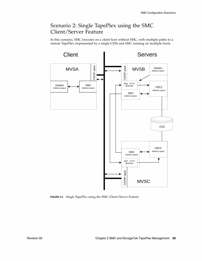
Scenario 2: Single TapePlex using the SMC Client/Server FeatureIn this scenario, SMC executes on a client host without HSC, with multiple paths to a remote TapePlex (represented by a single CDS) and HSC running on multiple hosts.
Client Servers
MVSA
SMCAddress space
Initiator Address space
MVSC
TC
P/IP
sta
ck
TC
P/IP
sta
ck
HSC1Address space
MVSB
TC
P/IP
sta
ck
SMCAddress space
InitiatorAddress space
SMC HTTP SERVER
HSC2Address space SMC
Address space
SMC HTTP SERVER
CDS
FIGURE 3-2 Single TapePlex using the SMC Client/Server Feature
SMC Configuration Scenarios
40 Configuring and Managing SMC 7.0 • July 2014 Revision 05
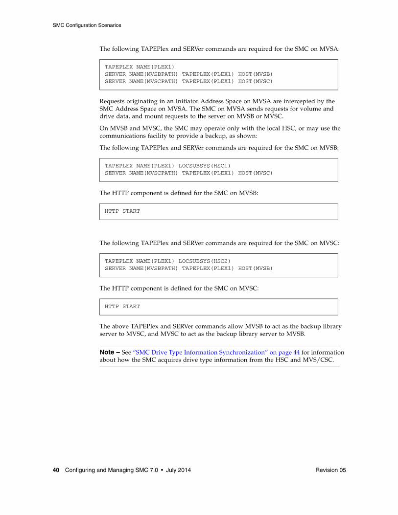
The following TAPEPlex and SERVer commands are required for the SMC on MVSA:
Requests originating in an Initiator Address Space on MVSA are intercepted by the SMC Address Space on MVSA. The SMC on MVSA sends requests for volume and drive data, and mount requests to the server on MVSB or MVSC.
On MVSB and MVSC, the SMC may operate only with the local HSC, or may use the communications facility to provide a backup, as shown:
The following TAPEPlex and SERVer commands are required for the SMC on MVSB:
The HTTP component is defined for the SMC on MVSB:
The following TAPEPlex and SERVer commands are required for the SMC on MVSC:
The HTTP component is defined for the SMC on MVSC:
The above TAPEPlex and SERVer commands allow MVSB to act as the backup library server to MVSC, and MVSC to act as the backup library server to MVSB.
Note – See “SMC Drive Type Information Synchronization” on page 44 for information about how the SMC acquires drive type information from the HSC and MVS/CSC.
TAPEPLEX NAME(PLEX1) SERVER NAME(MVSBPATH) TAPEPLEX(PLEX1) HOST(MVSB)SERVER NAME(MVSCPATH) TAPEPLEX(PLEX1) HOST(MVSC)
TAPEPLEX NAME(PLEX1) LOCSUBSYS(HSC1) SERVER NAME(MVSCPATH) TAPEPLEX(PLEX1) HOST(MVSC)
HTTP START
TAPEPLEX NAME(PLEX1) LOCSUBSYS(HSC2) SERVER NAME(MVSBPATH) TAPEPLEX(PLEX1) HOST(MVSB)
HTTP START

SMC Configuration Scenarios
Revision 05 Chapter 3 SMC and StorageTek TapePlex Management 41
Scenario 3: Two TapePlexes Accessed by a Single SMCIn this scenario, a single SMC communicates with two TapePlexes (represented by two CDSs).
Client Servers
HSC0Address space
MVSA
SMCInitiatorAddress space
TC
P/IP
sta
ck
HSCR CDSHSCL CDS
HSC1Address space
MVSB
TC
P/IP
sta
ck
SMCAddress space
MVSC
TC
P/IP
sta
ck
HSC2Address space SMC
Address space
SMC HTTP SERVER
SMC HTTP SERVER
FIGURE 3-3 Two TapePlexes Accessed by a Single SMC
SMC Configuration Scenarios
42 Configuring and Managing SMC 7.0 • July 2014 Revision 05
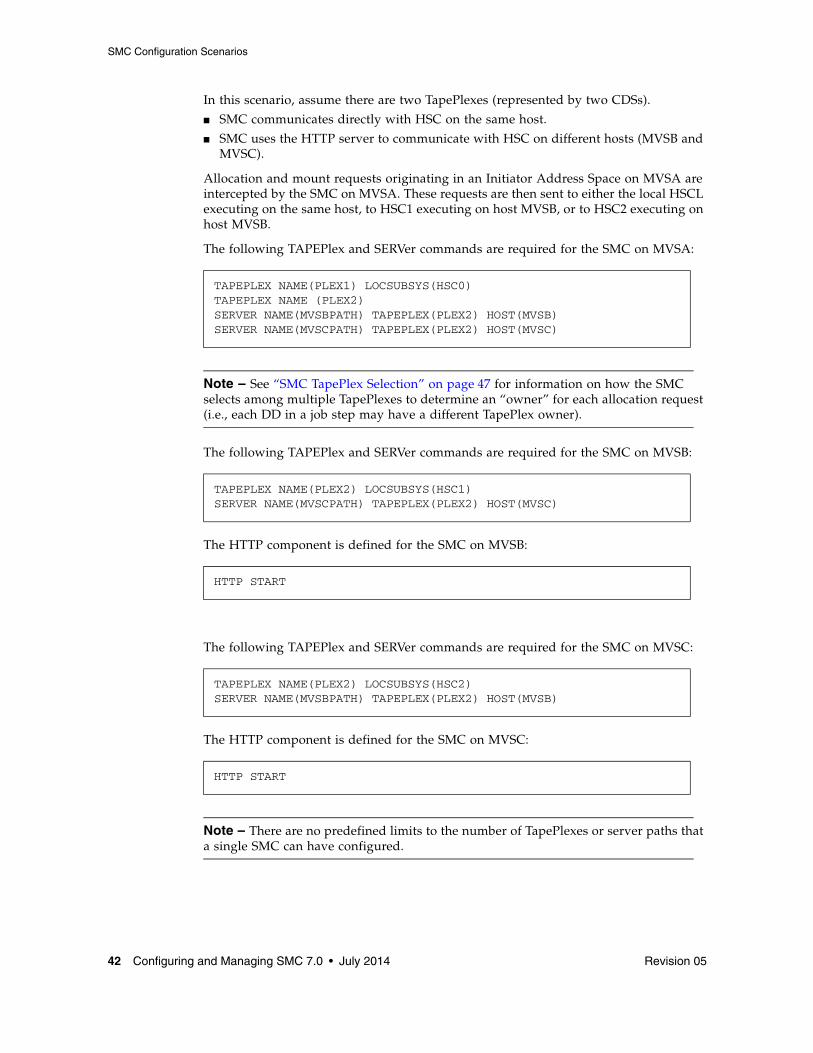
In this scenario, assume there are two TapePlexes (represented by two CDSs).
■ SMC communicates directly with HSC on the same host.
■ SMC uses the HTTP server to communicate with HSC on different hosts (MVSB and MVSC).
Allocation and mount requests originating in an Initiator Address Space on MVSA are intercepted by the SMC on MVSA. These requests are then sent to either the local HSCL executing on the same host, to HSC1 executing on host MVSB, or to HSC2 executing on host MVSB.
The following TAPEPlex and SERVer commands are required for the SMC on MVSA:
Note – See “SMC TapePlex Selection” on page 47 for information on how the SMC selects among multiple TapePlexes to determine an “owner” for each allocation request (i.e., each DD in a job step may have a different TapePlex owner).
The following TAPEPlex and SERVer commands are required for the SMC on MVSB:
The HTTP component is defined for the SMC on MVSB:
The following TAPEPlex and SERVer commands are required for the SMC on MVSC:
The HTTP component is defined for the SMC on MVSC:
Note – There are no predefined limits to the number of TapePlexes or server paths that a single SMC can have configured.
TAPEPLEX NAME(PLEX1) LOCSUBSYS(HSC0)TAPEPLEX NAME (PLEX2) SERVER NAME(MVSBPATH) TAPEPLEX(PLEX2) HOST(MVSB)SERVER NAME(MVSCPATH) TAPEPLEX(PLEX2) HOST(MVSC)
TAPEPLEX NAME(PLEX2) LOCSUBSYS(HSC1) SERVER NAME(MVSCPATH) TAPEPLEX(PLEX2) HOST(MVSC)
HTTP START
TAPEPLEX NAME(PLEX2) LOCSUBSYS(HSC2) SERVER NAME(MVSBPATH) TAPEPLEX(PLEX2) HOST(MVSB)
HTTP START

SMC Configuration Scenarios
Revision 05 Chapter 3 SMC and StorageTek TapePlex Management 43
Client/Server Drive Address MappingSMC and HSC provide facilities that allow you to manage an environment in which drive addresses are different between client and server hosts. The following table provides scenarios to help you determine whether client/server drive address mapping is required, and what actions and facilities are required.
TABLE 3-1 SMC Client/Server Drive Address Mapping Scenarios
Scenario Drive Address Mapping - Action Required
■ Client/server processing is not used.
■ Each MVS host runs a copy of HSC.
None.
■ Client/server processing is used.■ Device addresses are identically
defined for all hosts participating in a single client/server network.
None.
■ Client/server processing is used.■ Device addresses are identically
defined for all hosts in a single client/server network, but not all devices are defined to all hosts.
Drive address mapping is not required. However, you must use the HSC SET SLIDRIVS utility to define all drive addresses on hosts that will be used as servers, even if the devices are not defined to the host. Refer to the ELS Command, Control Statement, and Utility Reference for more information about the SET SLIDRIVS utility.
■ Client/server processing is used.■ Device addresses are identically
defined to all HSC hosts, but one or more SMC client-only hosts use a different set of addresses for the same device.
Use the SMC DRIVemap operator command to map the SMC client host addresses to the HSC host addresses. SMC performs the necessary address translations in influencing allocations and requesting mounts from the server. Refer to the ELS Command, Control Statement, and Utility Reference for more information about the DRIVemap command.
■ Client/server processing is used.■ Two MVS hosts (MVS1 and
MVS2), both running HSC and SMC.
■ One MVS host (MVS3) running only SMC but defined as communicating to either of the two hosts as a server.
■ Device addresses are defined differently among all three hosts. For example:■ MVS1 (AA0-AAF)■ MVS2 (BA0-BAF) ■ MVS3 (CA0-CAF)
1. Since the SMC on MVS3 can communicate with either the MVS1 or MVS2 host for a particular mount event, you must use the HSC SET utility, SET DRVHOST, to designate one of these hosts as the “drive host master.” For example, MVS1 (AA0-AAF). Once the drive host master is specified in the HSC CDS, the addresses associated with that host master (AA0-AAF) are used by both MVS1 and MVS2 when communicating with the SMC. If desired, you can add a dummy host ID to be the HSC DRVHOST, and use nonexistent drive addresses to map to client addresses. For example, use the HSC SET NEWHOST utility to define hostname DRVDUMMY and define the device range as 000-00F. Refer to the ELS Command, Control Statement, and Utility Reference for more information about the HSC SET DRVHOST utility and HSC SET NEWHOST utility.
2. Use the SMC DRIVemap operator command on clients MVS2 and MVS3 to map drive addresses BA0-BAF and CA0-CAF to the server addresses AA0-AAF. Refer to the ELS Command, Control Statement, and Utility Reference for more information about the DRIVemap command.

SMC Configuration Scenarios
44 Configuring and Managing SMC 7.0 • July 2014 Revision 05
SMC Drive Type Information SynchronizationThe SMC acquires drive type information from the ELS library control systems, HSC and MVS/CSC using configuration queries sent from the SMC to each defined TapePlex.
■ For HSC subsystems, drive configuration changes are automatically recognized by the SMC for both local and remote systems.
■ For MVS/CSC subsystems, an SMC RESYNChronize command must be issued whenever the equivalent MVS/CSC command is issued. Refer to the ELS Command, Control Statement, and Utility Reference for more information about the RESYNChronize command.
Specifying Drive Type Information Using SMC UNITAttr CommandsThe SMC UNITAttr command allows you to augment or override information returned from ELS library control system configuration queries as required by the local host tape device configuration. Specifically, the UNITAttr command allows you to do the following:
■ Set MODEL=IGNORE for device addresses not available for this host.
■ Specify model types for nonlibrary devices on this host.
■ Specify NOTAPEPLEX for a nonlibrary device address or range on this host, that are TapePlex owned devices on other hosts.
■ Specify TapePlex ownership for a device address or range that is defined to multiple TapePlexes, but for this host the attached devices belong to the specified TapePlex.
■ Specify TapePlex ownership and model for devices that may be referenced by a mount after the SMC is started, but before the TapePlex is initialized.
Note – UNITAttr commands are not required, and should only be issued under the conditions described in this section.
Specifying SMC UNITAttr Commands for Inaccessible DevicesTo define devices that are represented by a UCB, but are not accessible from this host, issue an SMC UNITAttr command for each inaccessible device as follows:
UNITAttr MOdel(IGNORE) processing remains unchanged from previous releases. As a result, SMC does not include the device in any of its processing.
UNITATTR ADDR(ccuu) MODEL(IGNORE)

SMC Configuration Scenarios
Revision 05 Chapter 3 SMC and StorageTek TapePlex Management 45
Specifying SMC UNITAttr Commands for Nonlibrary DevicesTo define nonlibrary device types on this host, issue an SMC UNITAttr command for each nonlibrary device as follows:
A nonlibrary device is a StorageTek device that requires additional model information to be defined in order to differentiate it from other nonlibrary devices with similar UCB characteristics.
Specifying SMC UNITAttr Commands for Nonlibrary Devices with the Same Address as a TapePlex-Owned DeviceIf a device address for your host overlaps with a device address for a TapePlex owned device, and the TapePlex owned device is inaccessible from this host, issue an SMC UNITAttr command specifying the NOTAPEPlex parameter as follows:
As a result, if a TapePlex such as HSC claims ownership via data returned from a configuration query, NOTAPEPlex overrides the TapePlex. The configuration information is ignored and the device remains a nonlibrary device.
If you fail to specify NOTAPEPlex, the TapePlex configuration information overrides the UNITAttr specified without the NOTAPEPlex parameter, and the device definition changes from a nonlibrary to TapePlex owned device.
UNITATTR ADDR(ccuu) MODEL(model)
UNITATTR ADDR(ccuu) MODEL(model) NOTAPEPLEX

SMC Configuration Scenarios
46 Configuring and Managing SMC 7.0 • July 2014 Revision 05
Specifying SMC UNITAttr Commands for TapePlex-Owned Devices with the Same Address as Another TapePlex-Owned DeviceIf your configuration includes multiple TapePlexes with overlapping device addresses or ranges, and both TapePlexes are defined to the SMC, enter a UNITAttr command with the TAPEPlex parameter to establish which TapePlex owns the specified device or range on this host. Enter a UNITAttr command for each of the duplicate drive addresses as follows:
Example
Assume:
■ Host MVSA includes two TapePlexes, HSC1 and HSC2.
■ HSC1 includes a 9840 device range 2900-2903.
■ HSC2 includes a 4480 device range 2900-2903.
■ However, on MVSA, devices 2900-2903 are attached to HSC1. MVSA has no connection to the HSC2 device range.
Given this scenario, issue an SMC UNITATTR command as follows:
This command directs the SMC to ignore any configuration information for the specified devices from any TapePlex other than the specified TapePlex.
Note – If MVSA recognized address range 2900-2903 defined to HSC2 as a different address range (e.g. 4900-4903), MVSA would use the SET DRVHOST facilities (see page 43) to define address range 2900-2903 on HSC2 as address range 4900-4903 for any client configuration queries.
Specifying SMC UNITAttr Commands for Devices in TapePlexes that are Initialized After the SMCTo define TapePlex owned devices when tape jobs are executed after the SMC starts but before the TapePlex is initialized, enter an SMC UNITAttr command for all TapePlex owned devices as follows:
This directs the SMC to keep track of any tape policy for pending mounts, including VTCS MGMTCLAS.
UNITATTR ADDR(ccuu) MODEL(model) TAPEPLEX(name)
UNITATTR ADDR(2900-2903) MODEL(9840) TAPEPLEX(HSC1)
UNITATTR ADDR(2900-2903) MODEL(9840) TAPEPLEX(HSC1)...UNITATTR ADDR(9000-903F) MODEL(VIRTUAL) TAPEPLEX(HSC1)
SMC Configuration Scenarios
Revision 05 Chapter 3 SMC and StorageTek TapePlex Management 47
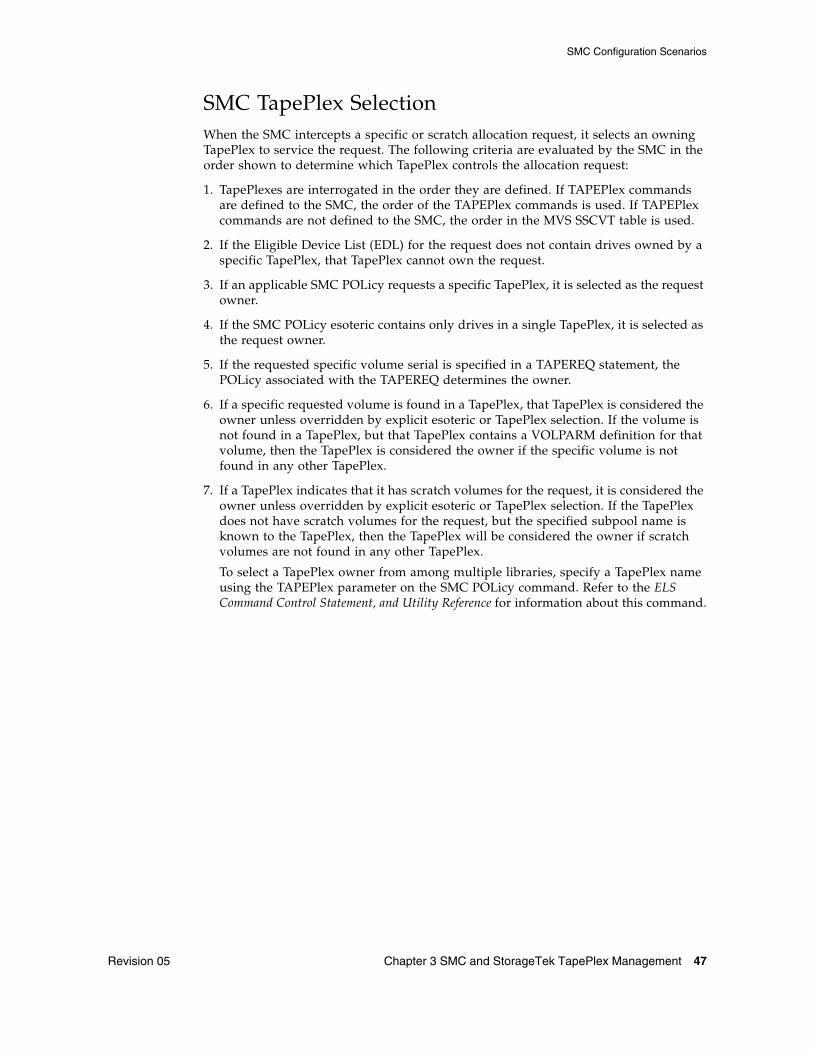
SMC TapePlex Selection When the SMC intercepts a specific or scratch allocation request, it selects an owning TapePlex to service the request. The following criteria are evaluated by the SMC in the order shown to determine which TapePlex controls the allocation request:
1. TapePlexes are interrogated in the order they are defined. If TAPEPlex commands are defined to the SMC, the order of the TAPEPlex commands is used. If TAPEPlex commands are not defined to the SMC, the order in the MVS SSCVT table is used.
2. If the Eligible Device List (EDL) for the request does not contain drives owned by a specific TapePlex, that TapePlex cannot own the request.
3. If an applicable SMC POLicy requests a specific TapePlex, it is selected as the request owner.
4. If the SMC POLicy esoteric contains only drives in a single TapePlex, it is selected as the request owner.
5. If the requested specific volume serial is specified in a TAPEREQ statement, the POLicy associated with the TAPEREQ determines the owner.
6. If a specific requested volume is found in a TapePlex, that TapePlex is considered the owner unless overridden by explicit esoteric or TapePlex selection. If the volume is not found in a TapePlex, but that TapePlex contains a VOLPARM definition for that volume, then the TapePlex is considered the owner if the specific volume is not found in any other TapePlex.
7. If a TapePlex indicates that it has scratch volumes for the request, it is considered the owner unless overridden by explicit esoteric or TapePlex selection. If the TapePlex does not have scratch volumes for the request, but the specified subpool name is known to the TapePlex, then the TapePlex will be considered the owner if scratch volumes are not found in any other TapePlex.
To select a TapePlex owner from among multiple libraries, specify a TapePlex name using the TAPEPlex parameter on the SMC POLicy command. Refer to the ELS Command Control Statement, and Utility Reference for information about this command.

SMC Configuration Scenarios
48 Configuring and Managing SMC 7.0 • July 2014 Revision 05
Revision 05 49
CHAPTER
4
Policy
OverviewTwo primary functions of the SMC are to influence MVS allocation to select devices compatible with tape volumes and to intercept MVS messages for tape mounts and dismounts to automate these operations for library and virtual drives.
For specific volumes, SMC allocation is primarily based on volume media and location.
For scratch volumes, SMC allocation and mount processing are primarily based on user policies. Policies to control scratch allocation and mounts may be selected using either the StorageTek DFSMS ACS interface or SMC TAPEREQ control statements.
Note – ■ User exits can also be used to select policies. Refer to the ELS Legacy Interfaces
Reference for more information.
■ A policy specified via DFSMS has priority over one specified via TAPEREQ, which in turn has preference over a policy specified in a user exit.

The SMC POLicy Command
50 Configuring and Managing SMC 7.0 • July 2014 Revision 05
The SMC POLicy CommandUse the SMC POLicy command to specify your policies for tape allocation and mount requests. This command allows you to create a named policy containing all of the attributes associated with an allocation or mount event, including MEDia, RECtech or MODel, SUBPool, ESOTeric, VTCS MGMTclas, and TAPEPlex.
The POLicy command can be used in conjunction with TAPEREQ statements or the StorageTek DFSMS interface to associate a named policy with allocation and mount requests.
Additionally, the POLicy command provides the ability to influence allocation variables during IDAX (MVS Interpreter/Dynamic Allocation Exit) processing. POLicy IDAX parameters can be used by both StorageTek DFSMS interface and TAPEREQ users to change variables normally supplied by JCL.
SMC policies are normally defined in a single data set or PDS member which is loaded at SMC startup using the SMC READ command. Additionally, the POLicy command may be issued at any time to add a new policy or replace the contents of an existing policy.
In the following sample SMCCMDS data set, the READ command loads the CNTL.PDS(POLMEM) data set containing the SMC policies:
FIGURE 4-1 Sample SMCCMDS Data Set
Note – ■ POLicy commands must be processed before the TREQDEF command if any
TAPEREQ statements reference policies by name.
■ If any POLicy command references a TAPEPlex, the TapePlex name must be defined using a TAPEPlex command before the POLicy command is processed.
■ Refer to the ELS Command, Control Statement, and Utility Reference for more information about the SMC POLicy command, SMSDef command, and TAPEREQ control statement.
ALLOCDEF ZEROSCR(ON,INSIDE)MSGDEF CASE(MIXED)TAPEPLEX NAME(HSCPLEX) LOCSUB(HSC0)READ DSN(‘CNTL.PDS(POLMEM)’)TREQDEF DSN(‘CNTL.PDS(TREQMEM)’)

SMC Policy and Esoteric Preferencing
Revision 05 Chapter 4 Policy 51
SMC Policy and Esoteric PreferencingThe SMC POLicy command allows you to preference devices during the allocation process. The ESOTeric parameter can specify a list containing a maximum of eight esoterics. During drive exclusion, devices in any of the listed esoterics are included. During drive prioritization, devices are ordered according to their position in the esoteric list. This feature allows you to do the following:
■ Prefer faster or slower models of equivalent drives.
■ Prefer a certain device type (e.g. 9940) if drives are available but select an alternative device type if preferred drives are busy.
By default, SMC prefers drives based on the following criteria in order:
1. specific volume LSM location
2. esoteric list
3. LSM scratch count.
The relative weight can be changed using the POLicy PREFer parameter. Refer to the ELS Command, Control Statement, and Utility Reference for more information.

SMC Policy at IDAX
52 Configuring and Managing SMC 7.0 • July 2014 Revision 05
SMC Policy at IDAXSMC processing at IDAX (MVS Interpreter/Dynamic Allocation Exit) allows specification of additional user policies based on the SMC IDAX command setting and the tape policies specified in individual SMC POLicy commands.
SMC IDAX processing allows you to change the JCL parameters for esoteric, volume count, expiration date or retention period, or subsystem and program name, based on policies specified in named SMC policy objects.
These IDAX policy features are enabled by the SMC IDAX command, which allows you to:
■ Specify that IDAX policies are applied based on TAPEREQ. The IDAX command parameter POLICY(ON) specifies that SMC should perform a TAPEREQ lookup for a policy name at IDAX if no SMC DFSMS policy is supplied.
■ Specify that SMC IDAX processing must execute before IBM DFSMS interface processing occurs. The IDAX command parameter SEQUENCE(FIRST) specifies that SMC IDAX processing precedes StorageTek DFSMS processing.
■ Specify that MOD data sets are treated as new (MOD(ON)).
The SMC POLicy command is used to set the policies to be applied during IDAX. All policy parameters that begin with the letters “IDAX” are applied only if the SMC IDAX command parameter POLICY(ON) is specified. These parameters include:
■ IDAXESOTERIC
This parameter specifies the name of an esoteric to be substituted for the JCL esoteric. IDAXESOTERIC may also be applied when the JCL statement does not contain any unit information. Unlike the POLICY ESOTERIC parameter, which is used to specify devices as a subset of the JCL esoteric, the IDAXESOTERIC performs a “true” esoteric substitution.
■ IDAXEXPDT and IDAXRETPD
These parameters are mutually exclusive and allow you to specify a retention period or expiration date to the DD statement, overriding any value that may have been specified in the JCL.
■ IDAXVOLCNT
This parameter allows you to override the volume count parameter specified in the JCL.
■ IDAXSUBSYS and IDAXPROGRAM
These parameters can be used to direct an allocation to use Oracle’s StorageTek ExHPDM (Extended High-Performance Data Mover).

SMC Policy at IDAX
Revision 05 Chapter 4 Policy 53
SMC Esoteric Substitution at IDAXSMC can perform esoteric substitution at IDAX using either the POLicy command IDAXESOTERIC parameter. When SMC performs esoteric substitution at IDAX, the original unit is replaced with a different unit (esoteric). Any valid esoteric can be substituted; for example, you can substitute a disk esoteric for a tape esoteric.
Note – ■ If your SMC IDAX processing modifies units which were optionally disk, or changes
tape units to disk, it is recommended that you specify the IDAX command parameter SEQUENCE(FIRST) to allow SMC DFSMS processing to precede IBM DFSMS processing. This ensures that tape and disk data sets are managed as intended.
■ New allocations that are DFSMS-managed are not eligible for SMC IDAX esoteric substitution.
■ SMC performs esoteric substitution for all DISP=NEW data sets.
■ By default, the SMC treats a DISP=MOD data set as pre-existing and does not perform esoteric substitution. SMC performs esoteric substitution for DISP=MOD data sets only if the IDAX command MOD(ON) parameter is specified and the first reference to the data set in the job's JCL specifies either DISP=MOD or DISP=NEW.
■ Unit affinity chains are separated if different members of the chain select POLICYs with different IDAXESOTERIC parameters.
■ VOL=REF chains within a job are validated and updated with the head-of-chain esoteric if necessary to ensure that volume references are honored.
■ You must specify SMSDef TEMPdsn(ON) before IDAX esoteric substitution can be performed for temporary data sets.
■ Refer to the ELS Command, Control Statement, and Utility Reference for more information about the IDAX and SMSDef commands.

SMC Policy and the TAPEREQ Control Statement
54 Configuring and Managing SMC 7.0 • July 2014 Revision 05
SMC Policy and the TAPEREQ Control StatementSMC TAPEREQ control statements are used to identify tape request attributes, including the tape policy associated with allocation and mount requests. The selected policy is based on the TAPEREQ selection criteria, such as data set name or job name.
The TAPEREQ POLicy parameter directs the SMC to reference an associated SMC policy defined by an SMC POLicy command.
TAPEREQ control statements reside in a definition data set specified by the TREQDEF operator command. TAPEREQ statements must be placed in this definition data set; they cannot be issued as operator commands.
Note – ■ Refer to the ELS Command, Control Statement, and Utility Reference for more
information about the SMC TAPEREQ control statement and POLicy command.
■ POLicy commands must be processed before the TREQDEF command if any TAPEREQ statements reference policies by name. See FIGURE 4-1 on page 50.
■ If your installation is using TAPEREQ statements without POLICY, or user exits, refer to the ELS Legacy Interfaces Reference for information about the interaction between POLICY and other TAPEREQ and user exit policy specifications.
Specifying TAPEREQ and Policy by Volume SerialUsing a combination of TAPEREQ statements and POLicy commands, SMC allows you to specify allocation policy based on specific volume serial numbers. In some cases this feature may allow you to replace HSC nonlibrary VOLATTRs with SMC TAPEREQ and POLicy commands.
Note – The VOLSER keyword on a TAPEREQ statement is allowed only if the POLicy keyword is also specified and references a previously defined SMC policy with the keyword VOLTYPE(SPECIFIC).
Using policy associated with volume serials allows you to:
■ Define different volume characteristics for the same volume serial for different clients.
For example, suppose that volser AAAAAA exists in the TapePlex on an HSC server with a media of STK1R, but on a specific client, volume AAAAAA is a nonlibrary standard cartridge. The following combination of POLicy commands and TAPEREQ statements allows the SMC to bypass the volume lookup for volume AAAAAA and use the specified policy information:
POLICY NAME(MANVOL) VOLTYPE(SPECIFIC) MEDIA(STANDARD) NOTAPEPLEX
TAPEREQ VOLSER(AAAAAA) POLICY(MANVOL)
SMC Policy and the TAPEREQ Control Statement
Revision 05 Chapter 4 Policy 55
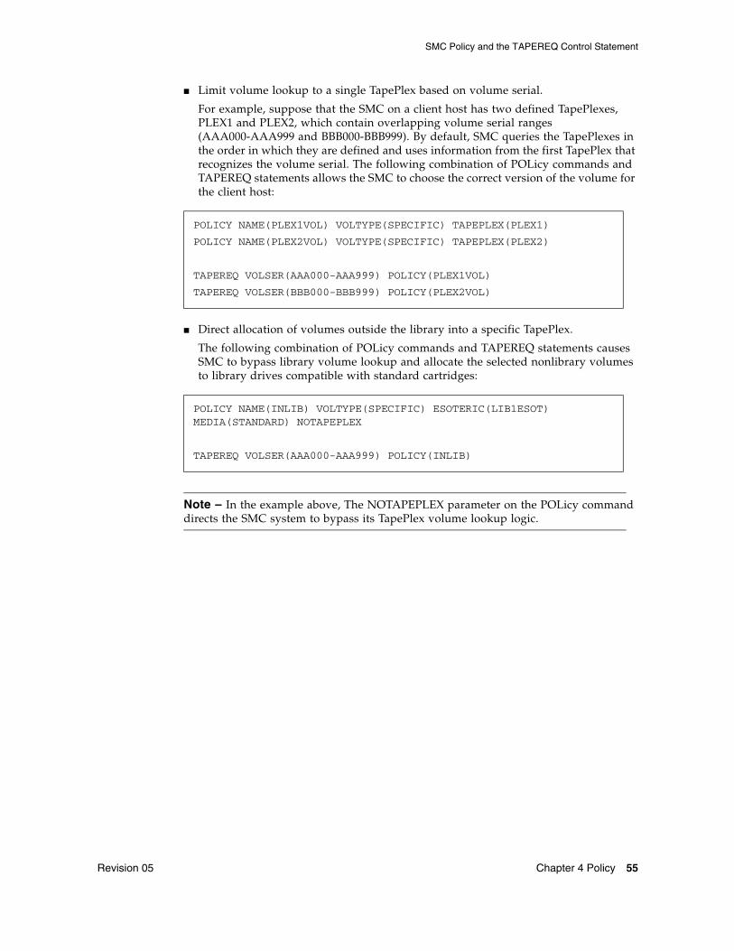
■ Limit volume lookup to a single TapePlex based on volume serial.
For example, suppose that the SMC on a client host has two defined TapePlexes, PLEX1 and PLEX2, which contain overlapping volume serial ranges (AAA000-AAA999 and BBB000-BBB999). By default, SMC queries the TapePlexes in the order in which they are defined and uses information from the first TapePlex that recognizes the volume serial. The following combination of POLicy commands and TAPEREQ statements allows the SMC to choose the correct version of the volume for the client host:
■ Direct allocation of volumes outside the library into a specific TapePlex.
The following combination of POLicy commands and TAPEREQ statements causes SMC to bypass library volume lookup and allocate the selected nonlibrary volumes to library drives compatible with standard cartridges:
Note – In the example above, The NOTAPEPLEX parameter on the POLicy command directs the SMC system to bypass its TapePlex volume lookup logic.
POLICY NAME(PLEX1VOL) VOLTYPE(SPECIFIC) TAPEPLEX(PLEX1)
POLICY NAME(PLEX2VOL) VOLTYPE(SPECIFIC) TAPEPLEX(PLEX2)
TAPEREQ VOLSER(AAA000-AAA999) POLICY(PLEX1VOL)
TAPEREQ VOLSER(BBB000-BBB999) POLICY(PLEX2VOL)
POLICY NAME(INLIB) VOLTYPE(SPECIFIC) ESOTERIC(LIB1ESOT) MEDIA(STANDARD) NOTAPEPLEX
TAPEREQ VOLSER(AAA000-AAA999) POLICY(INLIB)
SMC Policy and the TAPEREQ Control Statement
56 Configuring and Managing SMC 7.0 • July 2014 Revision 05
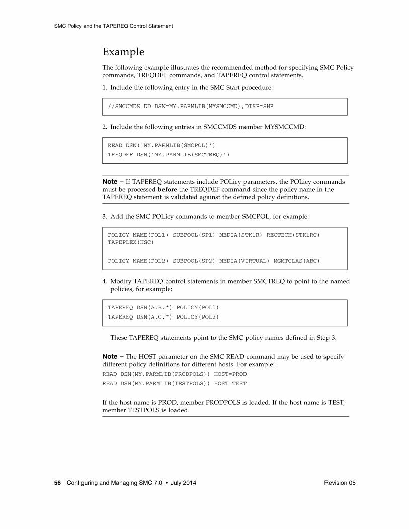
ExampleThe following example illustrates the recommended method for specifying SMC Policy commands, TREQDEF commands, and TAPEREQ control statements.
1. Include the following entry in the SMC Start procedure:
2. Include the following entries in SMCCMDS member MYSMCCMD:
Note – If TAPEREQ statements include POLicy parameters, the POLicy commands must be processed before the TREQDEF command since the policy name in the TAPEREQ statement is validated against the defined policy definitions.
3. Add the SMC POLicy commands to member SMCPOL, for example:
4. Modify TAPEREQ control statements in member SMCTREQ to point to the named policies, for example:
These TAPEREQ statements point to the SMC policy names defined in Step 3.
Note – The HOST parameter on the SMC READ command may be used to specify different policy definitions for different hosts. For example:READ DSN(MY.PARMLIB(PRODPOLS)) HOST=PROD
READ DSN(MY.PARMLIB(TESTPOLS)) HOST=TEST
If the host name is PROD, member PRODPOLS is loaded. If the host name is TEST, member TESTPOLS is loaded.
//SMCCMDS DD DSN=MY.PARMLIB(MYSMCCMD),DISP=SHR
READ DSN(‘MY.PARMLIB(SMCPOL)’)
TREQDEF DSN(‘MY.PARMLIB(SMCTREQ)’)
POLICY NAME(POL1) SUBPOOL(SP1) MEDIA(STK1R) RECTECH(STK1RC) TAPEPLEX(HSC)
POLICY NAME(POL2) SUBPOOL(SP2) MEDIA(VIRTUAL) MGMTCLAS(ABC)
TAPEREQ DSN(A.B.*) POLICY(POL1)
TAPEREQ DSN(A.C.*) POLICY(POL2)
SMC DFSMS Processing
Revision 05 Chapter 4 Policy 57
SMC DFSMS ProcessingThe SMC interface to DFSMS provides the ability to select an SMC POLICY by returning a MGMTCLAS name from your StorageTek DFSMS ACS routines.
Note – An alternative method for using the SMC DFSMS interface is described in the ELS Legacy Interfaces Reference.
Enabling/Disabling the SMC DFSMS InterfaceTo enable the SMC DFSMS interface, specify the SMS parameter of the ALLOCDef command as follows:
To disable the SMC DFSMS interface, specify the SMS parameter of the ALLOCDef command as follows:
Tailoring the SMC DFSMS InterfaceThe SMSDef command can be used to tailor the default SMC DFSMS support for your installation’s requirements. This command provides the ability to include or bypass certain SMC DFSMS functions. Refer to the ELS Command, Control Statement, and Utility Reference for more information about the SMSDef command.
ALLOCDEF SMS=ON
ALLOCDEF SMS=OFF

SMC DFSMS Processing
58 Configuring and Managing SMC 7.0 • July 2014 Revision 05
Defining StorageTek DFSMS ACS Routines to Specify MGMTCLASSTORCLAS and MGMTCLAS can be specified by executing an Automatic Class Selection (ACS) routine.
Note – STORCLAS and MGMTCLAS JCL parameters are not supported by the SMC DFSMS interface due to conflicts with IBM MVS DFSMS. Using the STORCLAS JCL parameter causes a data set to become IBM DFSMS-managed, and the MGMTCLAS JCL parameter requires an IBM DFSMS-managed data set. Similarly, DFSMS routines that do not test for the &ACSENVIR=’STKTAP1' variable result in the data set becoming IBM DFSMS-managed, and cannot be used by the SMC DFSMS interface.
It is recommended that you specify SMSDef MGMTPol (ALL) to direct SMC to process all DFSMS returned management class names as policy names.
The SMC SMSDef operator command is used to tailor default SMC DFSMS support. It allows you to include or bypass certain SMC DFSMS functions. Refer to the ELS Command, Control Statement, and Utility Reference for more information about this command.
Invoking ACS RoutinesIBM DFSMS invokes ACS routines with the variable &ACSENVIR set to ALLOC before the SMC invokes the ACS routines with variable &ACSENVIR set to STKTAP1.
The SMC invokes the ACS routines at the following points in processing:
JES2■ SSI55 Interpreter/Dynamic Allocation Exit (IDAX)■ SSI24 common allocation■ Mount message interception
JES3■ SSI55 Interpreter/Dynamic Allocation Exit (IDAX)■ JES3 Converter/Interpreter (C/I)■ SSI23 JES3 Dynamic Allocation■ JES3 Main Device Scheduler (MDS)■ Mount message interception

SMC DFSMS Processing
Revision 05 Chapter 4 Policy 59
ACS Routine OrderThe ACS routines are invoked in the following order:
1. data class
2. storage class
3. management class
4. storage group.
Management class and storage group ACS routines are called only if a storage class is assigned.

SMC DFSMS Processing
60 Configuring and Managing SMC 7.0 • July 2014 Revision 05
DFSMS Automatic Class Selection (ACS) Routine Environment for SMCThe following list of read-only variables is passed by SMC to DFSMS when the information is available to the SMC. Not all variables are available for every call to the ACS routines. In particular, processes that occur in the JES3 address space, such as MDS, do not provide the SMC access to the MVS control blocks that contain the values for these fields. See the descriptions of each DFSMS interface for exceptions.
■ &ACSENVIR (equals STKTAP1 for the SMC interface)■ &ALLVOL■ &ANYVOL ■ &DATACLAS■ &DD■ &DSORG■ &DSN■ &DSTYPE■ &EXPDT■ &FILENUM■ &JOB■ &LABEL■ &LIBNAME■ &NVOL■ &PGM■ &RETPD■ &SYSNAME■ &SYSPLEX■ &UNIT.
In the STKTAP1 environment, the &ANYVOL variable is used only to match a specific VOLSER and does not contain the “REF=xx” values for VOL=REF allocations.
The &DATACLAS field is set when the JCL DD statement specifies this parameter.
&LIBNAME is set to character “3” if SMSDef TEMPdsn(ON) is specified and the current data set being processed is a temporary data set.
If your installation uses the IGDACSXT routine to modify the read-only variables before the DFSMS ACS routine calls, be aware that the following variables, even if initialized, are not passed to the DFSMS ACS routines when &ACSENVIR is set to STKTAP1.
■ &ACCT_JOB■ &ACCT_STEP■ &GROUP■ &MSGVP■ &USER■ &XMODE
Refer to the IBM publication DFSMSdfp Storage Administration Reference for more information about constraints when using read-only variables.
SMC DFSMS Processing
Revision 05 Chapter 4 Policy 61
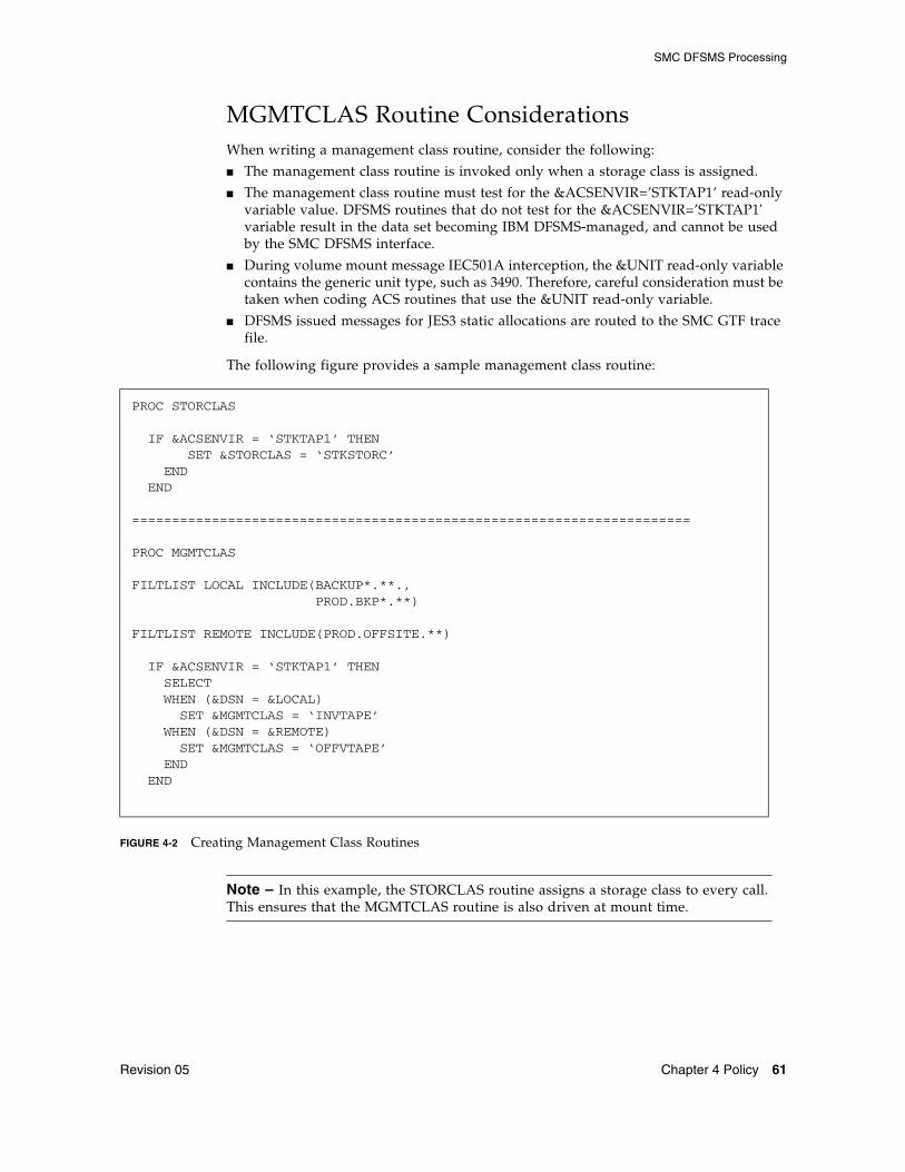
MGMTCLAS Routine ConsiderationsWhen writing a management class routine, consider the following:
■ The management class routine is invoked only when a storage class is assigned.
■ The management class routine must test for the &ACSENVIR=’STKTAP1’ read-only variable value. DFSMS routines that do not test for the &ACSENVIR=’STKTAP1' variable result in the data set becoming IBM DFSMS-managed, and cannot be used by the SMC DFSMS interface.
■ During volume mount message IEC501A interception, the &UNIT read-only variable contains the generic unit type, such as 3490. Therefore, careful consideration must be taken when coding ACS routines that use the &UNIT read-only variable.
■ DFSMS issued messages for JES3 static allocations are routed to the SMC GTF trace file.
The following figure provides a sample management class routine:
FIGURE 4-2 Creating Management Class Routines
Note – In this example, the STORCLAS routine assigns a storage class to every call. This ensures that the MGMTCLAS routine is also driven at mount time.
PROC STORCLAS
IF &ACSENVIR = ‘STKTAP1’ THEN SET &STORCLAS = ‘STKSTORC’ END END
======================================================================
PROC MGMTCLAS
FILTLIST LOCAL INCLUDE(BACKUP*.**., PROD.BKP*.**)
FILTLIST REMOTE INCLUDE(PROD.OFFSITE.**)
IF &ACSENVIR = ‘STKTAP1’ THEN SELECT WHEN (&DSN = &LOCAL) SET &MGMTCLAS = ‘INVTAPE’ WHEN (&DSN = &REMOTE) SET &MGMTCLAS = ‘OFFVTAPE’ END END

SMC DFSMS Processing
62 Configuring and Managing SMC 7.0 • July 2014 Revision 05
Availability of Read-only VariablesDuring DFSMS ACS routine processing, the SMC sets the values for all read-only variables when the information is available. Not all information is available for each process for which the SMC calls ACS routines.
JES2■ At allocation time and at mount time processing of message IEF233A, the &UNIT
read-only variable is set by the SMC to the value specified by the UNIT= parameter of the DD statement. At mount time processing of message IEC501A, the SMC sets the &UNIT read-only variable to the generic unit type, such as 3490.
■ During dynamic allocation, the &DATACLAS value can be specified by coding the DADACL text unit. However, this value is not available to the SMC when processing mount message IEF233A.
JES3During JES3 C/I POSTSCAN processing, the following read-only variables are not available to the SMC:
■ &DATACLAS (if specified in JCL)■ &EXPDT■ &PGM■ &RETPD
During SSI23 dynamic allocation processing, all read-only variables are available to the ACS routines.
During JES3 MDS processing, the following read-only variables are not available to the SMC:
■ &DATACLAS (if specified in JCL)■ &EXPDT■ &PGM■ &RETPD
During IAT5210 mount message processing, the following read-only variables are not available to the SMC:
■ &DATACLAS (if specified in JCL)■ &EXPDT■ &PGM■ &RETPD■ &UNIT (does not contain the original esoteric but does contain the selected device
number, such as 0A10)
When processing mount message IEF233A for a dynamic allocation, the &DATACLAS value specified by the SVC99 text unit DADACL is not available.
When processing mount message IEC501A, the SMC sets the &UNIT read-only variable to the generic unit type, such as 3490.
Note – Each SMC interaction with DFSMS invokes all levels of ACS routines. The variable availability listed above applies to all ACS routines.

SMC DFSMS Processing
Revision 05 Chapter 4 Policy 63
Validating DFSMS ACS Routine ExecutionDFSMS provides the following ways to validate correct ACS routine execution:
■ DFSMS WRITE statement in the ACS routines■ DFSMS ISMF test function
When the SMC invokes the DFSMS ACS routines, all messages issued by DFSMS WRITE statements are routed to the GTF trace file if SMC tracing is active.
Note – ■ DFSMS WRITE statements are only sent to the SYSMSG data set for the SSI55
Interpreter/Dynamic Allocation Exit (IDAX) esoteric substitution phase.
■ Refer to the publication DFSMS/MVS DFSMSdfp Storage Administration Reference for further information about writing and testing DFSMS ACS routines.

SMC DFSMS Processing
64 Configuring and Managing SMC 7.0 • July 2014 Revision 05
Revision 05 65
CHAPTER
5
Allocation
OverviewA primary function of the SMC is to influence the operating system selection of tape drives during allocation to ensure that acceptable devices are selected in a StorageTek TapePlex and virtual environment. In addition, the SMC creates a preferred list of acceptable devices based on specific volume location, scratch load balancing, and user policies. Although the mechanism by which allocation is influenced differs between JES2 (or JES3 without SETUP) and JES3 with tape setup, the logic that selects the acceptable and preferred devices is the same for all systems.
Generally, SMC allocation cannot add devices to the original list created from the job’s JCL. It can only eliminate unacceptable devices and preference the remaining acceptable devices. However, by using the SMC IDAX interface (see page 53) or the SMC DFSMS interface (see page 57), you can replace the original esoteric in the JCL with any other esoteric, which may have different devices or device types.
The SMC determines the list of drives acceptable for each tape allocation by applying a series of criteria (referred to as "exclusion levels") to the initial set of devices, removing those drives that do not meet the criteria. This process is referred to as drive exclusion.
If the SMC attempts to apply a particular exclusion criterion and as a result, all remaining eligible drives are excluded, messages SMC0045 and SMC0046 are displayed indicating that a particular exclusion criterion could not be applied. However, the exclusion process continues, with the SMC applying subsequent criteria if possible.
SMC allocation may intentionally cause a job to fail allocation when it appears that a mount to any of the drives in the available list would fail. For example, a volume with a media STK1R cannot be physically mounted on a 9490 drive, and a nonlabeled tape cannot be virtual.
Additionally, some customers may prefer to fail a job in allocation rather than use undesired scratch media or require a specific volume to be ejected and entered into a different ACS. The SMC ALLOCDEF (or ALLOCJOB) MINLVL parameter can be used to fail jobs in allocation, or conversely, to override the SMC default behavior of failing jobs in allocation.
■ Setting MINLVL=0 specifies that the SMC should NEVER fail a job in allocation.
■ The default MINLVL, 2, indicates that jobs should be failed in allocation only for incompatible media or virtual label type.

Overview
66 Configuring and Managing SMC 7.0 • July 2014 Revision 05
Customers may set MINLVL to higher values if desired. See “Drive Exclusion” below for detailed information about SMC exclusion levels for specific and scratch volumes.
After all exclusion criteria have been applied, the remaining drives are arranged in order of their desirability based on policy, volume location or scratch count, and last mount time. This process is referred to as drive prioritization. During this process, the SMC also sets flags in MVS control blocks to indicate that the mount should be deferred until OPEN, unless a policy specifies that mounts should not be deferred.
Note – SMC allocation does not consider the status of the drives (e.g. offline, busy) when selecting drives eligible for an allocation request. If all SMC-selected drives are unavailable, the job enters allocation recovery.
Drive Exclusion
Revision 05 Chapter 5 Allocation 67
Drive ExclusionThe drive exclusion process includes the following steps:
1. The SMC examines the initial list of eligible devices for each tape DD in each jobstep (or dynamic allocation), and gathers policy information from various sources, including DFSMS ACS routines, a combination of SMC POLicy commands and TAPEREQ control statements, and user exits.
2. The SMC uses policy information to select the “owning TapePlex” for each tape allocation. If a POLICY specifies a TapePlex name, or specifies an esoteric that contains devices controlled by a single TapePlex, then that TapePlex is selected as the owner for allocation.
When multiple TapePlexes are eligible for ownership of the application, the first TapePlex that returns a successful status is selected as the owner. For a specific volume request, a successful response indicates that the volume is in the library or is defined as a virtual volume. For a scratch request, a successful response indicates that the TapePlex has available scratch volumes for the requested media and scratch subpool.
3. The SMC performs "volume lookup" by communicating with one or more TapePlexes, and gathering information about specific volume characteristics and location, as well as available scratch volumes. If the SMC is unable to obtain this information from a TapePlex, the ALLOCDef FAILnoinfo parameter may be used to control whether the job is allowed to fail in allocation or to proceed based only on available policies.
4. The SMC applies the information received from volume lookup and policies using an ordered set of levels, with the earliest (lowest numbered) levels applied first and least important levels applied later, e.g. level 2 is considered more important, and is applied before level 3, etc.
Whenever application of a particular exclusion would eliminate all drives, the SMC ignores the criterion and continues with the next exclusion level.
Note – ■ See Chapter 4, “Policy” for a description of SMC Policy specification.
■ Refer to the ELS Legacy Interfaces Reference for more information about user exits.

Drive Exclusion
68 Configuring and Managing SMC 7.0 • July 2014 Revision 05
Drive Exclusion - Specific VolumesFor a specific volume allocation, the SMC excludes drives in order from lowest exclusion level to highest based on the criteria in the following table. The lower the level number, the more important the exclusion criteria.
TABLE 5-1 Drive Exclusion Levels (Specific Request)
Level Specific Volume Criteria Keyword†
†Keywords associated with each exclusion level are specified in the exclusion criteria displayed in message SMC0046.
1 For non-labeled (NL) specific volume requests, exclude all virtual drives.Exclude all MODEL=IGNORE drives.Exclude drives incompatible with the volume media.Primary source: external volume label Secondary source: VOLATTR MEDIA parameter The volume media can be obtained from the volume label or from an HSC VOLATTR statement MEDIA parameter.
VIRTUALLABEL MEDRECTECH
2*
*Level 2 is the default minimum level.
For virtual volumes only, exclude virtual drives that reside in an inaccessible VTSS or in a VTSS to which a migrated virtual volume cannot be recalled.
AVAILVTSS
3 Exclude drives based on the required recording technique.Source: VOLATTR RECTECH parameter or volume density (i.e. 9840A/B and 9840C).
VOLATTRRECTECH
4 Exclude drives based on user location policies.Primary source: POLicy or TAPEREQ ESOTERIC parameter.Secondary source: Specific volume user exit (08/13) or affinity separation exit (10/12) return codes.
USERPOLICY
5 Exclude drives based on the SMC ALLOCDEF EXTVOLESOT esoteric. EXTVOLESOT
6 Exclude drives based on volume location type (i.e. library or nonlibrary). LOCTYPE
7 Exclude drives based on the ACS location of the volume (for library volumes), and the resident VTSS for virtual volumes.
ACSORVTSS
8 Exclude drives based on the requested recording technique. Primary source: DFSMS data class recording technique.Secondary source: POLicy or TAPEREQ RECTECH parameter.
POLRECTECH

Drive Exclusion
Revision 05 Chapter 5 Allocation 69
ExampleThe following example illustrates how the SMC applies exclusion levels to influence the allocation of specific volumes.
JCL:
Policy specification:
Volume lookup information:
■ Specific volume VOL123
■ SMC volume lookup indicates that VOL123 has a media type of STK1R single density in TapePlex HSCLIB ACS 0.
Allocation exclusion processing:
1. Starting at exclusion level 1, the SMC excludes all non-9840 devices (those not compatible with the volume media).
2. Level 2 has no effect.
3. The SMC does not exclude any devices at level 3 since there was no HSC VOLATTR to limit the volume to single density drives.
4. The SMC excludes all drives not in the esoteric A19840B or A19840A.
5. The SMC does not exclude any devices at level 5 because the volume is in the TapePlex.
6. The SMC excludes all nonlibrary drives, if any remain.
7. The SMC attempts to exclude all drives not in ACS 0. However, since the remaining devices at this point include only 9840 drives in ACS1 (based on the esoterics A19840B and A19840A), there are no drives remaining in the EDL after this exclusion.
The SMC then "backs up" to the EDL as it was prior to the level 7 exclusion and issues messages SMC0045/SMC0046 specifying ACSORVTSS as the conflicting criterion.
Only drives in esoterics A19840B and A19840A remain eligible, based on exclusion level 4.
8. Level 8 has no effect.
Allocation preference processing:
During drive prioritization, SMC assigns a higher preference value to drives in esoteric A19840B, and a lower preference value to drives in A19840A.
//DDNAME DD DSN=ABC.DEF,DISP=OLD
POLICY NAME(POL1) VOLTYPE(SPECIFIC) ESOTERIC(A19840B,A19840A)
RECTECH(STK1RB)
TAPEREQ DSN(ABC.*) POLICY(POL1)

Drive Exclusion
70 Configuring and Managing SMC 7.0 • July 2014 Revision 05
Drive Exclusion - Scratch VolumesFor a scratch volume allocation, the SMC excludes drives in order from lowest exclusion level to highest based on the criteria in Table 3. The lower the level number, the more important the exclusion criteria.
TABLE 5-2 Drive Exclusion Levels (Scratch Request)
Level Scratch Volume Criteria Keyword*
*Keywords associated with each exclusion level are specified in the exclusion criteria displayed in message SMC0046.
1 For nonlabeled (NL) scratch volume requests, exclude all virtual drives. Exclude all MODEL=IGNORE drives.
VIRTUALLABEL
2 For virtual volumes only, exclude virtual drives that reside in an inaccessible VTSS, and all drives in VTSSs that do not support the requested VTCS Management Class.
AVAILVTSS
3 Exclude drives based on the requested media.Primary source: DFSMS data class media specification.Secondary source: POLicy or TAPEREQ MEDIA parameter.Tertiary source: Scratch volume user exit (02/04) virtual media return code or virtual esoteric.
POLMEDIA
4 Exclude drives based on user location policies.Primary source: POLicy or TAPEREQ ESOTERIC parameter.Secondary source: Scratch volume user exit (02/04) or affinity separation exit (10/12) return codes.
USERPOLICY
5 Exclude drives based on the media of available scratch volumes in subpool.Primary source: POLicy or TAPEREQ SUBPOOL parameter.Secondary source: Scratch volume user exit (02/04) subpool name or number.Tertiary source: Scratch subpool 0 (default subpool), containing all real and virtual scratch tapes including those in named subpools.
SUBPOOL
6 Exclude library, nonlibrary, or virtual drives based on location of available library or virtual scratch volumes.
LOCTYPE
7 Exclude drives based on the SMC ALLOCDef command ZEROSCR parameter. ZEROSCRATCH
8 Exclude drives based on the requested recording technique.Primary source: DFSMS data class recording technique.Secondary source: POLicy or TAPEREQ RECTECH parameter.
POLRECTECH

Drive Exclusion
Revision 05 Chapter 5 Allocation 71
Example - Real Scratch VolumeThe following example illustrates how the SMC applies the exclusion levels to influence the allocation of scratch volumes.
JCL:
Policy specification:
Scratch user exit returns use SUBPOOL(SP2) and ESOTERIC(XYZ).
Volume lookup information:
SMC volume lookup reports that TapePlex HSCLIB has scratch volumes in subpool SP1.
Allocation exclusion processing:
1. Starting at exclusion level 1, the SMC excludes drives which have an SMC UNITATTR command specifying MODEL=IGNORE.
2. Level 2 has no effect.
3. The SMC excludes all devices that do not support a media ECART.
4. Because POLicy is specified, the user exit esoteric XYZ is ignored, and level 4 has no effect. Message SMC0197 is issued to indicate this.
5. The SMC excludes all drives not compatible with the scratch volumes in subpool SP1 (TAPEREQ policy overrides user exit policy).
6. The SMC excludes all nonlibrary drives.
7. If scratch volumes for SP1 exist only in a single ACS, the SMC excludes drives in other ACSs.
8. The SMC excludes all remaining drives that do not have a MODEL of 9490.
//DDNAME DD DSN=DEF.GHI,DISP=NEW
POLICY NAME(POL2) VOLTYPE(SCRATCH) SUBPOOL(SP1) MEDIA(ECART) MODEL(9490)
TAPEREQ DSN(DEF.*) POLICY(POL2)
SMC ALLOCDEF ZEROSCR(ON)
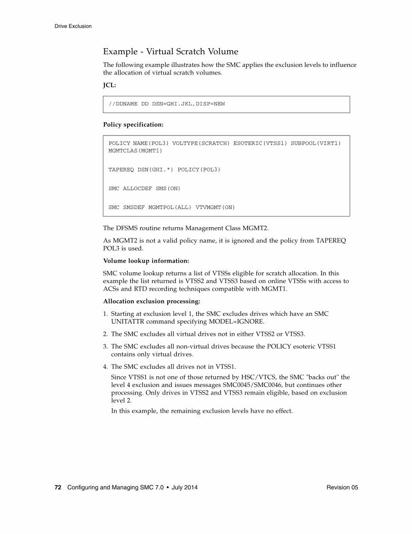
Drive Exclusion
72 Configuring and Managing SMC 7.0 • July 2014 Revision 05
Example - Virtual Scratch VolumeThe following example illustrates how the SMC applies the exclusion levels to influence the allocation of virtual scratch volumes.
JCL:
Policy specification:
The DFSMS routine returns Management Class MGMT2.
As MGMT2 is not a valid policy name, it is ignored and the policy from TAPEREQ POL3 is used.
Volume lookup information:
SMC volume lookup returns a list of VTSSs eligible for scratch allocation. In this example the list returned is VTSS2 and VTSS3 based on online VTSSs with access to ACSs and RTD recording techniques compatible with MGMT1.
Allocation exclusion processing:
1. Starting at exclusion level 1, the SMC excludes drives which have an SMC UNITATTR command specifying MODEL=IGNORE.
2. The SMC excludes all virtual drives not in either VTSS2 or VTSS3.
3. The SMC excludes all non-virtual drives because the POLICY esoteric VTSS1 contains only virtual drives.
4. The SMC excludes all drives not in VTSS1.
Since VTSS1 is not one of those returned by HSC/VTCS, the SMC "backs out" the level 4 exclusion and issues messages SMC0045/SMC0046, but continues other processing. Only drives in VTSS2 and VTSS3 remain eligible, based on exclusion level 2.
In this example, the remaining exclusion levels have no effect.
//DDNAME DD DSN=GHI.JKL,DISP=NEW
POLICY NAME(POL3) VOLTYPE(SCRATCH) ESOTERIC(VTSS1) SUBPOOL(VIRT1) MGMTCLAS(MGMT1)
TAPEREQ DSN(GHI.*) POLICY(POL3)
SMC ALLOCDEF SMS(ON)
SMC SMSDEF MGMTPOL(ALL) VTVMGMT(ON)

Affinity Separation
Revision 05 Chapter 5 Allocation 73
Affinity SeparationExplicit unit affinity is an MVS facility that allows volumes associated with two separate JCL DD statements, or allocation requests, to be mounted serially on the same drive. A request for all generations of a GDG group (GDG ALL chain) can be considered as a GDGALL affinity.
The SMC makes no distinction between these two types of affinity. When processing an affinity chain, the drive exclusion process examines each allocation in the chain separately up to and including the minimum exclusion level. The chain is always separated when the minimum exclusion level processing results in lists of eligible drives, for two or more members of the chain, that do not contain common drives.
For example:
DD1 specifies a data set on 9840 or T9840B media and DD2 specifies a data set on longitudinal media. Drive exclusion level 1 for specific volumes creates a list of eligible drives for each DD according to volume media required. The two lists do not contain a common drive. As a result, the SMC breaks the affinity chain between DD1 and DD2, and the two DD statements no longer represent one drive allocation but two separate allocation requests.
Affinity Head-Of-ChainFor SMC affinity chain processing, the head of the affinity chain containing only scratch or only specific volumes is the first DD statement in the chain. If an affinity chain contains both scratch and specific volumes, the first specific volume is treated as the head of chain.
User Policy Influence on Affinity SeparationAfter the minimum level of drive exclusion and affinity separation completes, user policy influences the remaining affinity separation decisions.
The ALLOCDef or ALLOCJob SEPLvl parameter can be used to indicate that affinity chains NOT be separated based on the exclusion levels described in this chapter. User exits 10 and 12 can also be used to control affinity separation. Refer to the ELS Legacy Interfaces Reference for more information.
//DD1 DD UNIT=CART,DSN=MY.STK1R.DATASET,DISP=OLD
//DD2 DD UNIT=AFF=DD1,DSN=MY.LONGI.DATASET,DISP=OLD
Drive Prioritization
74 Configuring and Managing SMC 7.0 • July 2014 Revision 05
Drive PrioritizationSMC drive priority is assigned based on the following criteria:
■ For specific volumes, drives in LSMs closest to the volume are preferred. The SMC sets equal priority value for drives that are located the same number of passthrus away from the specific volume.
■ For scratch volumes, drives in LSMs with the largest number of scratch volumes matching the policy-requested media and rectech are preferred.
■ The POLicy ESOTeric list causes drives to be preferred according to the order specified in the esoteric list.
■ The POLicy PREFer parameter indicates the relative priority of LSM location (location for specific volumes), the esoteric list (esoteric for both scratch and specific volumes) and scratch count (count for scratch volumes) in determining the preference value of each device.
Note – Refer to the ELS Legacy Interfaces Reference for other prioritization factors.
After a final list of drives has been selected for allocation, the preference order of the eligible drives (after considering LSM and drive type preferencing) is selected based on a "last use" algorithm.
To reduce excessive wear on allocated drives, the SMC assigns drive preference values by rotation based on the "last mount time" for each drive. This value is examined for every drive in the final drive list. The drive that had the most recent mount is located, and the drive immediately following it in the list is selected as the most preferred for the current allocation.
Note – This algorithm does not apply to virtual drives.

Deferring Mounts
Revision 05 Chapter 5 Allocation 75
Deferring MountsBy default, the SMC defers all automated tape mounts. The SMC ALLOCDef command DEFER parameter can be set to override this default. For optimal performance, it is recommended that you use the default DEFER(ON). Refer to the ELS Command, Control Statement, and Utility Reference for more information about the SMC ALLOCDef command.
Note – Virtual mounts are always deferred.
SMC Allocation ExceptionsThe SMC does not influence the following types of cartridge tape allocation:
■ Demand allocation (i.e., request for a specific drive(s))
Note – The SMC performs DEFER processing for demand allocation.
■ Allocations excluded explicitly by entering the ALLOCJob command BYPASS parameter. Refer to the ELS Command, Control Statement, and Utility Reference for more information about the SMC ALLOCDef command.
■ Allocations where the list of eligible devices contains only devices that are "unknown" (i.e., not virtual, not library, and not defined in an SMC UNITAttr command).
■ DFSMS-managed allocation. An SMS-managed data set is defined as a data set that has a storage class defined. A storage class is assigned when either:
■ The STORCLAS parameter is specified on the DD statement. ■ An installation-written ACS routine selects a storage class for a new data set.
SMC Allocation Processing - JES2 Operating System Hooks
76 Configuring and Managing SMC 7.0 • July 2014 Revision 05
SMC Allocation Processing - JES2 Operating System HooksThe SMC examines all I/O device allocations on a JES2 system to determine whether to process the allocation request.
The SMC uses the MVS subsystem interface (SSI) IEFJFRQ Subsystem Function Request exit to gain control during tape allocation events. The SMC takes control in the JES2 environment for these Subsystem Functions:
■ SSI55 - DFSMS Interpreter/Dynamic Allocation Exit (IDAX)
■ SSI24 - common allocation
■ SSI78 - tape allocation
SSI55 IDAX (Interpreter/Dynamic Allocation Exit) During MVS JCL interpretation processing, IDAX provides an opportunity to replace the JCL unit parameter, volume count, retention period or expiration date, and other specific JCL attributes for DISP=NEW (and optionally DISP=MOD) data sets.
Note – This function is optional. See “SMC Esoteric Substitution at IDAX” on page 53 for information about implementing SMC IDAX processing and specifying IDAX policy attributes.
SSI24 Common Allocation During SSI24 common allocation processing, the SMC performs the following processes to arrive at the best set of eligible drives:
■ Drive exclusion
■ Unit affinity separation
■ Defer processing (when CA1RTS is set to ON)
■ EDL updated with the drive exclusion results (when MIACOMPAT is set to ON)
The results of the drive exclusion process are not reflected in MVS control blocks until tape allocation time, unless MIACOMPAT or CA1RTS is set to ON.
The results of unit affinity separation are used to update MVS VOLUNIT entries in the SIOT.

SMC Allocation Processing - JES2 Operating System Hooks
Revision 05 Chapter 5 Allocation 77
SSI78 Tape Allocation During SSI78 tape allocation processing, the SMC performs the following:
■ Updates to MVS control blocks based on drive exclusion results (unless MIACOMPAT is set to ON)
■ Drive prioritization
■ Mount deferral (unless CA1RTS is set to ON)
The SMC sets all unacceptable drives to ineligible status and assigns a priority to each drive that remains eligible for the allocation. The higher the priority, the more likely the device will be chosen for the mount.
The SMC updates the IEFSSTA control blocks for mount deferral, drive exclusion, and prioritization during SSI78 processing.
SMC Allocation Processing - JES3 Considerations
78 Configuring and Managing SMC 7.0 • July 2014 Revision 05
SMC Allocation Processing - JES3 Considerations
SMC Allocation - JES3 Not Managing DrivesIf JES3 is not managing any devices and SETUP=NONE has been specified on the JES3 STANDARDS initialization statement, the SMC operates the same as it does in a JES2 environment.
If JES3 is not managing any cartridge drives but is managing other types of devices, specify the J3NOSET parameter on the EXEC statement of the SMC START procedure. See “Creating the SMC START Procedure” on page 25 for more information. When J3NOSET is specified, the SMC operates the same as it does in a JES2 environment.
If either SETUP=NONE or J3NOSET is specified, no Type 1 modifications need to be installed on your JES3 system.
SMC Allocation - JES3 Managing Drives The SMC supports JES3-managed drives. JES3 manages drives through SETUP processing, which allocates drives identified on SETNAME statements when JOB, HWS (high watermark setup), or THWS (tape high watermark setup) is specified on the SETUP parameter of the JES3 STANDARDS initialization statement. In this environment, JES3 must manage all cartridge drives for the SMC to operate correctly.
SMC support operates during the following MVS subsystem interfaces (SSIs) and JES3 component phases:
■ SSI55 Interpreter/Dynamic Allocation Exit (IDAX)
■ JES3 Converter/Interpreter (C/I)
■ SSI23 JES3 Dynamic Allocation
■ JES3 Main Device Scheduler (MDS)
■ SSI24 common allocation
SSI55 IDAX (Interpreter/Dynamic Allocation Exit) SMC SSI55 processing is identical in JES2 and JES3. See “SSI55 IDAX (Interpreter/Dynamic Allocation Exit)” on page 76 for more information.
SMC Allocation Processing - JES3 Considerations
Revision 05 Chapter 5 Allocation 79
JES3 Converter/Interpreter (C/I) During JES3 C/I POSTSCAN processing, the SMC substitutes an esoteric to eliminate unacceptable drives from the allocation. The SMC performs the following processes to arrive at the best set of eligible drives:
■ Drive exclusion
■ Affinity separation
■ Esoteric unit name replacement to exclude unacceptable devices
At the end of JES3 C/I POSTSCAN processing, the SMC can defer the allocation until the job enters the initiator according to the SMC ALLOCDef command DEFER parameter. Also, at this point of processing, fetch messages can be suppressed according to the ALLOCDef command FETCH parameter.
SSI23 JES3 Dynamic Allocation During SSI23 JES3 Dynamic Allocation processing, the SMC performs the same functions for dynamic allocations that the POSTSCAN C/I processes for common allocations:
■ Drive exclusion
■ GDGALL affinity separation
■ Esoteric unit name replacement
■ Mount deferral
JES3 Main Device Scheduler (MDS) At the beginning of JES3 MDS processing, the SMC provides the ability to suppress fetch messages for dynamic allocation requests according to the SMC ALLOCDef command FETCH parameter.
During MDS device selection, the SMC sets preference values for drives according to their relative desirability, that is, JES3 selects the available drive with the highest preference value for the allocation.
SSI24 Common Allocation If a mount has been deferred until the job enters an initiator, during SSI24 common allocation processing, the mount may be deferred further until the data set is opened. The SMC ALLOCDef command DEFER parameter determines whether or not the mount is deferred.

SMC Allocation Processing - JES3 Considerations
80 Configuring and Managing SMC 7.0 • July 2014 Revision 05
Esoteric Unit Name Replacement in JES3After drive exclusion and affinity separation successfully complete, each allocation may have a new list of eligible drives. The search begins to find an esoteric containing that exact list of drives. The SMC replaces the original JCL unit name in the Intermediate Job Summary Table (IJS) with this new esoteric.
The search for the "perfect" esoteric begins with the original JCL unit name or the unit name from the catalog entry for that data set. For example, assume the data set being allocated has been cataloged with the unit name 3490. The following table lists all "3490" drives in the system.
JES3 groups devices by XTYPE names and groups XTYPE names by esoterics. The following example shows DEVICE statements coded in the JES3 initialization parameters:
TABLE 5-3 3490 Drive List
ACS0 ACS1 Nonlibrary Location
0A10: 9490 0C10: 9490 0E10: 9490
0B10: 9840 0C11: 9490 0E11: 9490
DEVICE,TYPE=TA33490,XTYPE=(ACS09490,CA),JNAME=CA10, JUNIT=(A10,MVS1,TAP,ON),XUNIT=(A10,MVS1,TAP,ON)
DEVICE,TYPE=TA33490,XTYPE=(ACS09840,CA),JNAME=CA11, JUNIT=(B10,MVS1,TAP,ON),XUNIT=(B10,MVS1,TAP,ON)
DEVICE,TYPE=TA33490,XTYPE=(ACS19490,CA),JNAME=CC10, JUNIT=(C10,MVS1,TAP,ON),XUNIT=(C10,MVS1,TAP,ON)
DEVICE,TYPE=TA33490,XTYPE=(ACS19490,CA),JNAME=CC11, JUNIT=(C11,MVS1,TAP,ON),XUNIT=(C11,MVS1,TAP,ON)
DEVICE,TYPE=TA33490,XTYPE=(NLIB9490,CA),JNAME=CE10, JUNIT=(E10,MVS1,TAP,ON),XUNIT=(E10,MVS1,TAP,ON)
DEVICE,TYPE=TA33490,XTYPE=(NLIB9490,CA),JNAME=CE11, JUNIT=(E11,MVS1,TAP,ON),XUNIT=(E11,MVS1,TAP,ON)

SMC Allocation Processing - JES3 Considerations
Revision 05 Chapter 5 Allocation 81
Each unique location and device type pair has a unique XTYPE name. For example, the 9490 drive in ACS0 has a unique XTYPE name because it is the only 9490 in that location. The two nonlibrary 9490 drives share an XTYPE name because they are the same device type in the same location. An XTYPE should always include either a single device type or multiple compatible device types. For example, 9840A and 9840B are compatible device types and may be assigned to the same XTYPE.
XTYPE names are associated with esoteric unit names in the JES3 initialization parameters as shown here:
Assume that during drive exclusion processing, the SMC determined the volume specified for this allocation resides in ACS0 and requires a 9490 drive. The drive exclusion process eliminates groups of drives by XTYPE.
In the environment defined above, the following XTYPE groups are no longer eligible for the allocation:
■ ACS09840 - excluded at level 1 because T9840 drives are incompatible with the volume media
■ NLIB9490 - excluded at level 6 because the volume is in the library and these drives are not
■ ACS19490 - excluded at level 7 because the volume is in ACS0 and these drives are in ACS1
One XTYPE, ACS09490, remains eligible for allocation at the end of drive exclusion.
SMC esoteric unit name replacement now searches the SETNAME definitions for an esoteric that only contains the XTYPE ACS09490. For this allocation, the SMC selects the esoteric A09490 because it contains only XTYPE ACS09490 The A09490 esoteric replaces the original unit name, 3490, in the Intermediate Job Summary (IJS) table for that job.
If the example required two drives for the allocation (e.g., UNIT=(3490,2)) and the first volume to be mounted resides in ACS0, the results of drive exclusion would be as follows:
■ ACS09840 - excluded at level 1 because T9840 drives are incompatible with the volume media.
■ NLIB9490 - excluded at level 6 because the volumes are in the library and these drives are not.
■ Exclusion level 7 fails.
On entry to level 7, three drives remain, two drives defined to XTYPE ACS19490 and the other drive to XTYPE ACS09490. If XTYPE ACS19490 were excluded because of ACS location, only one drive would remain. This allocation requires two drives. Thus, exclusion level 7 does not exclude the drives in ACS1.
Two XTYPEs, ACS09490 and ACS19490, remain eligible for allocation at the end of drive exclusion. The SMC esoteric unit name replacement now determines that XTYPE ACS09490 cannot be used for the allocation.
SETNAME,XTYPE=ACS09490,NAMES=(CART,3490,LIBDRVS,ACS0DRVS,A09490)
SETNAME,XTYPE=ACS09840,NAMES=(CART,3490,LIBDRVS,ACS0DRVS,A09840)
SETNAME,XTYPE=ACS19490,NAMES=(CART,3490,LIBDRVS,ACS1DRVS,A19490)
SETNAME,XTYPE=NLIB9490,NAMES=(CART,3490,NLIBDRVS,NL9490)

SMC Allocation Processing - JES3 Considerations
82 Configuring and Managing SMC 7.0 • July 2014 Revision 05
IBM APAR OW38427 to JES3 introduced the restriction that multi-unit allocations use devices defined in the same XTYPEs. Since XTYPE ACS09490 only contains one drive, it cannot satisfy the allocation requirements. The SMC esoteric unit name replacement now searches the SETNAME definitions for an esoteric that only contains the XTYPE ACS19490. The A19490 esoteric replaces the original unit name, 3490, in the IJS for that job.
After the SMC has updated the IJS, JES3 C/I processing continues. JES3 creates a Job Summary Table (JST) from the IJS table and performs any high watermark setup (HWS) chaining. During HWS chaining, JES3 can also change the esoteric unit name in the JST after the SMC changes the esoteric. The HWSNAME initialization statements define which esoteric unit names are subsets of other esoteric unit names. This allows JES3 to reuse devices in following steps.
See “JES3 Initialization Parameter Considerations” on page 83 for more information about setting up your installation's JES3 DEVICE, SETNAME and HWSNAME statements.
Suppressing Fetch Messages in JES3 By the time JES3 C/I processing completes, the IJS becomes the JST that represents the job for the remainder of its existence. The JST reflects the esoteric substitutions made by the SMC and JES3. The next stage for the job is the Main Device Scheduler (MDS).
At the beginning of MDS processing, JES3 begins preparing the job for allocation. Asking the operator to fetch volumes is an optional phase in MDS. JES3 issues a fetch message when a job requires a volume that is not currently mounted and the SETPARAM statement FETCH parameter is set to YES (the default). If the SETPARAM statement also specifies ALLOCATE=MANUAL, jobs are placed on the volume wait queue until the operator retrieves the volume(s) and issues the *START SETUP command.
A customer's installation may not want to receive fetch messages for volumes in the library. To do so for common allocation requests (JCL statement allocation), install the SMC version of the JES3 user exit IATUX09. For dynamic allocation requests, install the SMC Type-1 modification to IATMDFE.
Use the SMC ALLOCDef FETCH parameter to control the issuing of fetch messages. FETCH(OFF) is the default and suppresses fetch messages for any volume that is to be mounted on a library drive. If fetch messages are desired for nonlibrary volumes that are to be mounted on a library drive, FETCH(NONLIB) should be entered.
Note – FETCH(NONLIB) causes another volume lookup request to the TapePlex, which can affect performance.
If your system is running with ALLOCATE=MANUAL as described above, when fetch messages are suppressed for a volume allocation, that allocation does not go onto the volume wait queue.
If your system is running with the SETPARAM statement set to FETCH=NO, or if you prefer to receive fetch messages for all volumes, then the IATMDFE Type-1 modification does not need to be applied to your system. The IATUX09 user exit also performs other functions and should be applied.
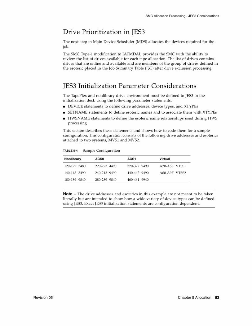
SMC Allocation Processing - JES3 Considerations
Revision 05 Chapter 5 Allocation 83
Drive Prioritization in JES3 The next step in Main Device Scheduler (MDS) allocates the devices required for the job.
The SMC Type-1 modification to IATMDAL provides the SMC with the ability to review the list of drives available for each tape allocation. The list of drives contains drives that are online and available and are members of the group of drives defined in the esoteric placed in the Job Summary Table (JST) after drive exclusion processing.
JES3 Initialization Parameter ConsiderationsThe TapePlex and nonlibrary drive environment must be defined to JES3 in the initialization deck using the following parameter statements:
■ DEVICE statements to define drive addresses, device types, and XTYPEs
■ SETNAME statements to define esoteric names and to associate them with XTYPEs
■ HWSNAME statements to define the esoteric name relationships used during HWS processing
This section describes these statements and shows how to code them for a sample configuration. This configuration consists of the following drive addresses and esoterics attached to two systems, MVS1 and MVS2.
Note – The drive addresses and esoterics in this example are not meant to be taken literally but are intended to show how a wide variety of device types can be defined using JES3. Exact JES3 initialization statements are configuration dependent.
TABLE 5-4 Sample Configuration
Nonlibrary ACS0 ACS1 Virtual
120-127 3480 220-223 4490 320-327 9490 A20-A5F VTSS1
140-143 3490 240-243 9490 440-447 9490 A60-A9F VTSS2
180-189 9840 280-289 9840 460-461 9940

SMC Allocation Processing - JES3 Considerations
84 Configuring and Managing SMC 7.0 • July 2014 Revision 05
JES3 DEVICE Initialization Statements DEVICE statements define the drives that JES3 can use to satisfy allocation requests. These statements define:
■ Drive addresses
■ JES3/MVS systems that can access the drives
■ Initial drive online status
■ Device type of the drive
The XTYPE parameter is especially important to SMC allocation. XTYPE connects devices with the same XTYPE value to a group of esoteric unit names. For example:
Devices 220-223 in ACS0 (TABLE 5-4 on page 83) have been associated with the XTYPE name DEV0220. This name allows JES3 to allocate a device from the group 200-223 when any of the esoteric unit names listed on the SETNAME statement associated with XTYPE DEV0220 are specified in JCL or in a catalog entry.
The SMC relies on each XTYPE group to be unique with regard to real drive type and location. In the list of drives for ACS0, the 4490 drives should not be defined with the same XTYPE as the 9490 drives. Also, the T9840 drives located in ACS0 should not be defined with the same XTYPE as the nonlibrary T9840 drives. Devices in different VTSSs should have different XTYPEs.
During SMC initialization, XTYPE groupings are examined to verify these XTYPE restrictions. If an XTYPE contains mixed devices types or mixed locations, the characteristics of the first drive in the XTYPE group defines the remaining drives.
The SMC configuration report utility shows XTYPE, esoteric, and drive information. Refer to the ELS Command, Control Statement, and Utility Reference for more information about the configuration report.
The following example shows how DEVICE statements can be coded for this sample configuration.
Note – Drives must be defined to MVS prior to defining them to JES3. Use the Hardware Configuration Definition (HCD) facility to assign MVS unit addresses to the devices in the I/O Configuration.
DEVICE,XTYPE=(DEV0220,CA),XUNIT
(220,MVS1,TAP,ON,220,MVS2,TAP,ON),
NUMDEV=4,...

SMC Allocation Processing - JES3 Considerations
Revision 05 Chapter 5 Allocation 85
JES3 SETNAME Initialization Statements The SETNAME statements define all esoteric unit names and device type names associated with JES3-managed devices. These esoteric unit names and device type names can be specified by the UNIT parameter on a DD statement or as the unit type in a cataloged data set entry.
DEVICE statements associate a set of drives with an XTYPE. The SETNAME statement associates the XTYPE with a group of esoteric unit names.
During SMC esoteric unit name replacement, the relationships among the devices, the XTYPEs, and the esoteric unit names enable the SMC to choose the optimal esoteric unit name.
Note – During allocation of specific volumes, the SMC attempts to substitute an esoteric containing only drives compatible with the volume. If all esoterics that are a subset of the original esoteric contain some drives not compatible with the volume (except for drives defined as MODEL=IGNORE in an SMC UNITAttr command), the SMC issues message SMC0068 and does not substitute for the original esoteric.
Therefore, to ensure the SMC's ability to perform esoteric substitution, you must define at least one esoteric containing only compatible drive types within each TapePlex. For example, if you have a single TapePlex that contains ECART and standard volumes and 9490, 4490 and 4480 drives, you must, at a minimum, define one esoteric containing only drives compatible with the ECART volumes (9490, 4490, and 4480 drives). You can also define other esoterics containing any desired combinations of these drive types.
For best SMC performance, define a unique esoteric for each drive type in each location. For example, an esoteric named A09840 can be defined to contain only the T9840 drives located in ACS0.
The following example shows how SETNAME statements can be coded for this single TapePlex configuration. The esoteric unit names specified in the NAMES parameter value list consist of the following:
CART All cartridge drives in the environment
NLCART All cartridge drives not in a library ACS
A0CART All cartridge drives in ACS0
A1CART All cartridge drives in ACS1
ALLxxxx All cartridge drives of the same device type, xxxx, independent of location
LIBxxxx All cartridge drives of the same device type, xxxx, in any library location
yyxxxx All cartridge drives of the same device type, xxxx, in location yy
zzzzzzzz All virtual devices in VTSS zzzzzzzz

SMC Allocation Processing - JES3 Considerations
86 Configuring and Managing SMC 7.0 • July 2014 Revision 05
The generic device type names, such as 3480 or SYS3480R, are also specified in the NAMES lists.
Refer to the appropriate version of the IBM JES3 Initialization and Tuning Reference for more information about esoteric unit name values for the SETNAME statement NAMES parameter.
* 3480/NONLIBRARY SETNAME,XTYPE=DEV120,NAMES=(SYS3480R,CART,3480,NLCART,NL3480) * * 3490/NONLIBRARY SETNAME,XTYPE=DEV0140,NAMES=(SYS3480R,SYS348XR,CART,3490,NLCART, ALL3490, NL3490) * * 9840/NONLIBRARY SETNAME,XTYPE=DEV0180,NAMES=(SYS3480R,SYS348XR,CART,3490,NLCART, ALL9840,NL9840) * * 4490/ACS0 SETNAME,XTYPE=DEV0220,NAMES=(SYS3480R,SYS348XR,CART,3490,A0CART, A04490,A0DEVT90) * * 9490/ACS0 SETNAME,XTYPE=DEV0240,NAMES=(SYS3480R,SYS348XR,CART,3490,A0CART, ALL9490,LIB9490,A09490,A0DEVT90) * * 9840/ACS0 SETNAME,XTYPE=DEV0280,NAMES=(CART,3590-1,A0CART,ALL9840,A09840) * * 9490/ACS1 SETNAME,XTYPE=ACS19490,NAMES=(SYS3480R,SYS348XR,CART,3490,A1CART, ALL9490,LIB9490,A19490) * * 9940/ACS1 SETNAME,XTYPE=DEV0460,NAMES=(CART,3590-1,A1CART,ALL9940,A19940) * * VIRTUAL DRIVES/VTSS1 SETNAME,XTYPE=DEV0A20,NAMES=(CART,3490,VIRTCART,VTSS1) * * VIRTUAL DRIVES/VTSS2SETNAME,XTYPE=DEV0A60,NAMES=(CART,3490,VIRTCART,VTSS2)

SMC Allocation Processing - JES3 Considerations
Revision 05 Chapter 5 Allocation 87
JES3 HWSNAME Initialization StatementsHWSNAME statements define which esoteric unit names are subsets of other esoteric unit names. Used during JES3 high watermark setup (HWS), these statements determine if a device can be reused from step to step.
The first HWSNAME TYPE parameter specifies the esoteric unit name, known as the major name, used during HWS processing. The following esoteric unit names, called minor names, can be used as an alternate to the major name.
The order of the minor names listed in the HWSNAME statement is the order in which they can be substituted for the major name.
For example:
and
JES3 HWS processing allocates two drives for this job. The Job Summary Table (JST) for the job after HWS shows the following esoterics for each DD allocation request:
■ STEP1 DD1 and STEP2 DD2 JST entries contain ALL4490 because ALL4490 appears in the minor name list before ALL3490.
■ STEP2 DD1 JST entry contains ALL3490.
HWSNAME TYPE=(3490,ALL4490,ALL9490,ALL3490)
//STEP1 EXEC PGM...//DD1 DD UNIT=3490,...//STEP2 EXEC PGM...//DD1 DD UNIT=ALL3490,...//DD2 DD UNIT=ALL4490,...

SMC Allocation Processing - JES3 Considerations
88 Configuring and Managing SMC 7.0 • July 2014 Revision 05
Another example shows how HWS names are used when allocating across step boundaries:
JES3 HWS begins with DD1 of STEP1 looking for an allocation in STEP2 that can use the same device. DD1 of STEP2 specifies 3490. The HWSNAME above for major name 3490 indicates that ALL9490 is an alternate (or minor) name for 3490. Therefore, STEP1 DD1 and STEP2 DD1 allocate the same drive. The JST entry for DD1 of STEP2 is not updated to reflect a new esoteric. The drive allocated for STEP1 DD2 is freed at the end of STEP1.
The minor names should not contain any devices that are not defined to the major name.
For example:
Assume the following:
■ A0CART contains drives 220-223, 240-243, and 280-289.
■ ALL9840 contains drives 180-189 and 280-289.
ALL9840 contains drives (180-189) not in A0CART. In this case, volumes inside the TapePlex requesting a T9840 drive may attempt to allocate to a drive outside the TapePlex after HWS processing by JES3. HWS processing occurs after SMC esoteric unit name replacement. Therefore, the HWSNAME definitions can affect the final allocation decision if JES3 also changes the esoteric unit name as in the first example.
//STEP1 EXEC PGM...//DD1 DD UNIT=ALL9490,...//DD2 DD UNIT=ALL4490,...//STEP2 EXEC PGM...//DD1 DD UNIT=3490
HWSNAME TYPE=(A0CART,ALL9840,...)

SMC Allocation Processing - JES3 Considerations
Revision 05 Chapter 5 Allocation 89
The best solution for this situation is to create unique esoteric unit names (by location and device type) so that the SMC can select an esoteric unit name that has no minor name. See the HWSNAME entries in the following example that have been coded for the sample configuration.
* GENERIC MAJOR NAMESHWSNAME TYPE=(SYS3480R)HWSNAME TYPE=(SYS348XR)HWSNAME TYPE=(3480,NL3480)HWSNAME TYPE=(3490,SYS348XR, ALL3490,ALL9490,LIB9490,A0DEVT90, A04490,A09490,A19490,NL3490,NL9840)HWSNAME TYPE=(3590-1, ALL9940, A09840,A19940)** ALL DRIVES IN THE COMPLEXHWSNAME TYPE=(CART,SYS3480R,SYS348XR,3490,3480,3590-1, ALL3490,ALL9840,ALL9490,ALL9940,LIB9490, A0CART,A1CART,NLCART,A0DEVT90, A04490,A09490,A09840,A19490,A19940, NL3480,NL3490,NL9840)** DRIVES BY DEVICE TYPEHWSNAME TYPE=(ALL3490,LIB9490,A0DEVT90,A09490,A19490,NL3490, VIRTCART,VTSS1,VTSS2)HWSNAME TYPE=(ALL9840,A09840,NL9840)HWSNAME TYPE=(ALL9490,LIB9490,A09490,A19490)HWSNAME TYPE=(ALL9940,A19940)** DRIVES BY LOCATIONHWSNAME TYPE=(LIB9490,A09490,A19490)HWSNAME TYPE=(NLCART,ALL3490,ALL3480,3480, NL3480,NL3490,NL9840)HWSNAME TYPE=(A0CART,A04490,A09490,A09840,A0DEVT90)HWSNAME TYPE=(A1CART,ALL9940,A19940,A19490)** DRIVES BY LOCATION AND DEVICE TYPEHWSNAME TYPE=(A0DEVT90,A04490,A09490)HWSNAME TYPE=(NL3480)HWSNAME TYPE=(NL3490)HWSNAME TYPE=(NL9840)HWSNAME TYPE=(A04490)HWSNAME TYPE=(A09490)HWSNAME TYPE=(A09840)HWSNAME TYPE=(A19490)HWSNAME TYPE=(A19940)** VIRTUAL DRIVESHWSNAME TYPE=(VIRTCART,VTSS1,VTSS2)HWSNAME TYPE=(VTSS1)HWSNAME TYPE=(VTSS2)

SMC Allocation Processing - JES3 Considerations
90 Configuring and Managing SMC 7.0 • July 2014 Revision 05
Esoteric Preferencing ConsiderationsThe POLicy ESOTeric list allows users to request a higher priority for devices in one esoteric over another.
To enable this processing, define an esoteric that contains all esoterics in the specified list. For example, in the sample configuration, the esoteric A0DEVT90 is used for esoteric substitution for the following policy:
Device Preferencing ConsiderationsThe DEVTpref parameter of the SMC TAPEREQ statement allows users to request a higher priority for one type of StorageTek 36-track drive during drive prioritization processing. A second or third model of 36-track drive can be specified as alternate choices. This device preferencing is applicable to a TapePlex configuration containing a mixture of 4490, 9490 and 9490EE cartridge drives.
To enable this processing, define an esoteric to include all the desired device types by ACS location or in the entire TapePlex configuration. In the sample configuration, the esoteric, A0DEVT90, serves this purpose for ACS0.
During drive exclusion, if a TAPEREQ indicated DEVT(9490,4490) for an allocation, the SMC could substitute A0DEVT90 for the original unit name if A0DEVT90 is a subset (e.g., UNIT=3490).
Note – JES3 HWS processing can change this esoteric to A09490 or A04490 when reusing drives across steps.
ZEROSCR Considerations When specifying the SMC ALLOCDef command parameter ZEROSCR with a value of ON, create esoteric unit names that span ACS boundaries. As an example, the following esoterics could be added to the sample installation:
■ CA0A1 - an esoteric containing all drives in ACS0 and ACS1
■ A0A1X490 - an esoteric containing all 4490 and 9490 drives in ACS0 and ACS1
Assume both ACSs contain scratch volumes.
■ If the scratch request does not specify media or recording technique, the SMC can substitute CA0A1 for CART.
■ If the scratch request asked for 36-track recording technique, the SMC can substitute A0A1X490 for 3490.
In this way, both ACSs remain eligible for the allocation.
Note – Once again, JES3 HWS can alter esoteric unit names after the SMC has selected its choice.
POLICY NAME(P1) ESOTERIC(A09490,A04490)

SMC Allocation Processing - JES3 Considerations
Revision 05 Chapter 5 Allocation 91
SMC Normal Operations The SMC runs on all processors that are active in a JES3 global and local environment. On both global and local processors, start the SMC and the library subsystem(s), the HSC, and/or MVS/CSC(s) before starting jobs requiring cartridge drives.
When the SMC and the library subsystem have initialized on the global processor and are communicating, the SMC performs drive exclusion, affinity separation, esoteric unit name replacement, fetch message suppression, drive prioritization, and mount deferral for both common and dynamic cartridge drive allocations. If the SMC has not completed initialization before jobs enter the JES3 C/I DSP, this processing is not performed. The PROMPT value on the NOSMC parameter of the SMCEHOOK macro delays one C/I DSP if the SMC has not initialized and reminds the operator to start the SMC.
When the SMC and the library subsystem have initialized on the local processor and are communicating, the SMC performs drive exclusion, affinity separation, and esoteric unit name replacement for dynamic cartridge drive allocations.
Note – ■ Refer to the publication Installing ELS for more information about the SMCEHOOK
macro and its parameters.
■ See Chapter 7, “Recovery Procedures” for recovery procedures related to the SMC, library subsystems, and JES3.

SMC Allocation Processing - JES3 Considerations
92 Configuring and Managing SMC 7.0 • July 2014 Revision 05
JES3 Constraints
Timing Between C/I and MDS A timing window exists between C/I processing and MDS processing. A requested volume's location or a scratch subpool count can change during the interval between these two processes. When this situation happens, one or more volumes may need to be ejected from or entered into an ACS.
JES3 High Watermark Setup and LSM Pass-Thru Processing When a job consists of multiple steps, JES3 HWS processing attempts to minimize the number of devices required. Thus a job consisting of multiple steps, each requesting one tape drive, can be allocated a single drive for the entire job. The following example shows the possible effects on pass-thru processing.
The following figure shows a library configuration containing four LSMs. All drives in the library are online and available.
LSM 0
LA
N0
LA
N1
LSM 2
LSM 1 LSM 3
CD CD
CD
CDCD
LC
U
LC
U
LC
U
LCU
CD CDCD CD
CD
CD
CD
CD
C28635
VOLUMES
EX0001 & EX0002
VOLUME EX0003
VOLUME EX0004
FIGURE 5-1 Volume Locations for the Pass-thru Example

SMC Allocation Processing - JES3 Considerations
Revision 05 Chapter 5 Allocation 93
The following example shows the JCL for the job:
Volumes EX0001 and EX0002 are in LSM0, EX0003 is in LSM1, and EX0004 is in LSM2 and all volumes are the same media and require the same recording technique. The SMC drive exclusion process picked the same esoteric for the allocation.
After the SMC drive exclusion process completes, JES3 HWS analysis determines that the maximum number of drives required for running the job is one. MDS processing allocates the device. Pass-thru processing occurs as follows:
■ If the allocated drive is attached to LSM0, the number of pass-thrus is two (volume EX0003 moves from LSM1, and volume EX0004 moves from LSM2).
■ If the allocated drive is attached to LSM1 or LSM2, the number of pass-thrus is three (volumes EX0001 and EX0002 move from LSM0, and either EX0003 or EX0004 moves, depending upon which LSM contains the drive).
■ If the allocated device is attached to LSM3, the number of pass-thrus is four (all volumes move to LSM3).
The SMC drive prioritization process uses the pass-thru counts when setting a priority for a drive. However, if the "preferred" drive is not available, other available drives can be selected.
//STEP1 EXEC//DD1 DD DSN=DSN.IN.LSM0,UNIT=3490,VOL=SER=(EX0001,EX0002)//*//STEP2 EXEC//DD1 DD DSN=DSN.IN.LSM1,UNIT=3490,VOL=SER=EX0003//*//STEP3 EXEC//DD1 DD DSN=DSN.IN.LSM2,UNIT=3490,VOL=SER=EX0004//*//STEP4 EXEC//DD1 DD DSN=DSN.IN.LSM0,UNIT=3490,VOL=SER=(EX0001,EX0002)

SMC Allocation Processing - JES3 Considerations
94 Configuring and Managing SMC 7.0 • July 2014 Revision 05

Revision 05 95
CHAPTER
6
Message Handling
OverviewThe SMC intercepts specific MVS, JES3, and Tape Management System (TMS) messages related to mount, dismount, and swap operations. When the intercepted message includes a drive defined to a TapePlex, the SMC directs the owning TapePlex to perform the requested operation.
Messages that are intercepted by the SMC are listed in Appendix A, “Intercepted Messages”.
Note – The IATUX71 user exit must be installed to allow JES3 mount messages to be processed. Refer to the publication Installing ELS for more information.
User Directed Message HandlingIf the SMC does not currently support the Tape Management System at your installation, you can still direct the SMC to intercept the specific messages issued by your TMS. Use the USERMsg operator command to define these additional messages. Refer to the ELS Command, Control Statement, and Utility Reference for more information.
User Exit 01 allows you to change or enhance actions taken on intercepted messages, and can direct the SMC to perform actions on messages that are not in the intercepted message list.
The SMC calls the user exit for each intercepted message. This includes the default messages listed in Appendix A, “Intercepted Messages” and all messages defined using the USERMsg command.
Note – ■ Only messages intercepted by the SMC are passed to the user exit.
■ The SMC does not support the user exit 01 return code of REPLY.

Message Handling Policies
96 Configuring and Managing SMC 7.0 • July 2014 Revision 05
Message Handling PoliciesThe SMC honors the following MVS and SMC policies related to mount, dismount, and swap message handling:
MVS PoliciesThe System Authorization Facility (SAF) can be used to protect tapes at the volume level (CLASS=TAPEVOL) using your current security software. If defined, the SMC honors the policies defined through the SAF interface regarding the write-protect requirement for a volume mounted on a library transport. The SMC invokes the SAF interface by issuing a RACROUTE macro, and protects read-only volumes through the ACS Virtual Thumbwheel (VTW) support.
SMC PoliciesThe SMC MOUNTDef command is used to control message handling (i.e., mount/dismount) options previously controlled by the HSC MNTD command, HSC input parameters and LIBGEN options, and the MVS/CSC ALTER command and input parameters.
These options control the automation of pending mounts, delete disposition at dismount time, whether messages are produced when a library volume is mounted outside the library, and when mount messages are rolled off the console.
Note – Refer to the ELS Command, Control Statement, and Utility Reference for more information about the MOUNTDef command.
Tape Management System Support
Revision 05 Chapter 6 Message Handling 97
Tape Management System SupportThe SMC interprets Mount, Dismount, and Swap messages from the following Tape Management Systems:
■ CA-1
■ CA-DYNAM/TLMS
■ DFSMSrmm
■ AutoMedia (Zara)
■ CONTROL-T
For tape management systems that supply a subpool, the subpool is interpreted by the SMC and used as the requested subpool name, unless overridden by user exit 01 or a TAPEREQ statement. Related messages include:
■ CTS002
■ CTT101A
■ CTT104A
■ TMS002

SMC Swap Processing
98 Configuring and Managing SMC 7.0 • July 2014 Revision 05
SMC Swap ProcessingThe SMC automates the swap process (I/O error or operator initiated) in the same manner as HSC enhanced swap processing. This eliminates the need for operators to find a compatible “swap-to” device when DDR has chosen an incompatible device. If the SMC cannot find a compatible swap-to device, or if all compatible devices are busy, the SMC issues a message and control is returned to DDR processing with no further SMC involvement. Note that enhanced swap processing is the only mode supported in SMC.
On JES3 systems, the SMC does not influence the swap-to device selection. The SMC does not issue SMC0107 or SMC0110. JES3 can select a compatible drive itself based on proper initialization deck definitions. The SMC still automates the swap when the IGF502E is received.
The SMC swap process begins when one of the following messages is issued:
If device XXX1 is known to the SMC as a library device, the SMC suppresses the message and begins the automatic swap process.
The SMC issues one of three messages:
Or when a compatible drive can be selected by the SMC:
Or when the MOUNTDEF SWAPLIMIT count has been exceeded:
If SMC0108 has been issued and MOUNTDEF SWAPAUTOREPLY is on then message IGF500D or IGF509D will be replied to with NO.
If SMC0233 has been issued and the bypassReply variable of MOUNTDEF SWAPLIMIT is OFF then message IGF509D will be replied to with NO.
Device XXX2 is the SMC-selected device that has been determined to be compatible for the swap. The SMC next suppresses the MVS IGF500D or IGF509D message and replaces the message with:
IGF500I SWAP XXX1 TO XXX2 - I/O ERRORIGF503I ERROR ON XXX1, SELECT NEW DEVICEIGF509I SWAP XXX1 - I/O ERROR
SMC0108 No compatible drive found for SWAP processing
SMC0107 SWAP volser from XXX1 to XXX2
SMC0233 SWAPLIMIT=NNNNNN exceeded; swap processing cancelled
SMC0110 Allow swap of volser from XXX1 to XXX2; Reply ‘Y’, or ‘N’ or DEVICE

HSC Mount-Related Messages
Revision 05 Chapter 6 Message Handling 99
The operator may approve the device selected, cancel the swap or choose a different device. If the operator selects a different device, the SMC accepts the device with no further compatibility checking.
If the reply is ‘Y’ or a new device, MVS issues the following message:
If XXX1 is a library owned device, the dismount of the volume is automated. If XXX2 is a library owned device, the mount of the volume is automated.
Note – Ensure that your MVS security package (e.g., RACF, TopSecret) is configured to grant SMC the necessary authority to respond to MVS swap messages IGF500D and IGF509D.
HSC Mount-Related MessagesCertain mount-related messages may still be issued by the HSC due to error conditions.
■ SLS0088D is issued when, due to an error condition, a repeated mount for the same volume is required.
■ SLS1075D is issued when a dismounted volume encounters an I/O or other type of error.
Managing HSC Mounts from the SMC ClientSMC client/server architecture provides the ability to perform management of certain mount/dismount exception conditions from the client console rather than from the server console. Conditions handled by the SMC include the following:
■ Displaying messages on the drive and console indicating the volume and its location for manual mounts when an LSM is offline.
■ When a drive is found to be loaded with another volume during a mount request from a job in execution or JES3 setup processing, the dismount is forced and the mount is automatically redriven based on the UCB outstanding mount status (or JES3 SETUNIT).
IGF502E PROCEED WITH SWAP OF XXX1 TO XXX2

Managing HSC Mounts from the SMC Client
100 Configuring and Managing SMC 7.0 • July 2014 Revision 05
Note – When a mount or dismount message is intercepted by SMC and directed to an HSC server, the SLS0107D message is not issued on the server or client. When a loaded drive condition is detected by the HSC for an SMC directed dismount, the HSC waits one minute for the drive to unload, and then terminates the dismount. If the dismount is performed as part of a mount request from the SMC, the loaded drive status is returned to the SMC, and the SMC then redrives the mount request if the mount is still pending.
■ When a drive or volume is in use by another process, verifying that the mount is still pending, periodically retrying the request, and allowing the operator to cancel or retry the request at any time.
■ When the TAPEPlex WTORdest Client option is selected, certain WTOR messages are not issued on the HSC server but are sent directly to the client console instead. The operator response to the message is then transmitted back to the server, as SMC redrives the mount or dismount to the server. The following HSC mount/dismount WTOR messages are currently supported with this option:
■ SLS0134■ SLS0905■ SLS2126■ SLS2905■ SLS2984■ SLS0109■ SLS4084
Refer to the publication ELS Messages and Codes for more information about these messages.

Revision 05 101
CHAPTER
7
Recovery Procedures
OverviewThis chapter describes recovery procedures used when the SMC, a TapePlex, or JES3 becomes inactive. Procedures for both JES2 and JES3 are included.
SMC Recovery Procedures (JES2)This section describes recovery procedures for the following problem scenarios:
■ Inactive SMC - active TapePlex
■ Active SMC - inactive TapePlex
■ Automating mount requests for inactive TapePlexes
■ Lost MVS mount requests for active TapePlexes
SMC Recovery Procedures (JES2)
102 Configuring and Managing SMC 7.0 • July 2014 Revision 05
Inactive SMC - Active TapePlexWhen the SMC fails while one or more TapePlexes remain active, the following functions are not performed:
■ Allocation processing
■ Automation of mount/dismount/swap messages
When this occurs, re-start the SMC.
Certain software products allow you to suspend processing that may require dynamic allocation. For example, if Data Facility Hierarchical Storage Manager (DFSMS/hsm) is installed on the local processor, you can issue commands to prevent this type of processing without stopping DFSMS/hsm.
Common allocations can be postponed by holding the job queue or purging all initiators. Refer to the appropriate IBM publication for more information about JES2 operator commands.
If the SMC MOUNTDef AUTOPendmount (ON) option was specified, outstanding mount messages are re-driven.
Active SMC - Inactive TapePlexWhen a TapePlex fails or is terminated, volumes and drives owned by that TapePlex become unknown to SMC. The following functions are not performed:
■ Volume lookup for allocation influencing
■ Automated mount processing
When this occurs, re-start the TapePlex and issue the SMC RESYNC command. The SMC re-establishes communication with the TapePlex and automates any outstanding mounts, regardless of the SMC MOUNTDef AUTOPendmount setting. See “Automating Mount Requests for Inactive TapePlexes” below for more information.
Certain software products allow you to suspend processing that may require dynamic allocation. For example, if Data Facility Hierarchical Storage Manager (DFSMS/hsm) is installed on the local processor, you can issue commands to prevent this type of processing without stopping DFSMS/hsm.
Common allocations can be postponed by holding the job queue or purging all initiators. Refer to the appropriate IBM publication for more information about JES2 operator commands.
Note – You can provide a backup path to a remote TapePlex that is automatically activated when the local HSC is discovered to be inactive. See Chapter 3, “SMC and StorageTek TapePlex Management” for more information.

SMC Recovery Procedures (JES2)
Revision 05 Chapter 7 Recovery Procedures 103
Automating Mount Requests for Inactive TapePlexesMVS mount requests for drives owned by inactive TapePlexes are automatically redriven when the corresponding TapePlexes are activated.
Lost MVS Mount Requests for Active TapePlexesAn MVS mount request may be lost when an LMU error occurs. Use this procedure if you suspect lost mounts.
1. Issue the following MVS command on the system requesting the mount to determine if any drives have a mount request pending:
2. Issue the following MVS command on the same system to determine which VOLSER to mount:
3. If the drive is defined to an HSC TapePlex, issue the HSC Mount command for the volume on the MVS system on which the HSC is active.
D R,L
D U,,,uuuu,1
SMC Recovery Procedures (JES3)
104 Configuring and Managing SMC 7.0 • July 2014 Revision 05
SMC Recovery Procedures (JES3)This section describes recovery procedures for the following problem scenarios:
■ Inactive SMC - active TapePlex
■ Active SMC - inactive TapePlex
■ Inactive JES3 on a local processor
■ Inactive JES3 on a global processor
■ Automating mount requests for inactive TapePlexes
■ Lost JES3 mount requests for active TapePlexes
■ Lost MVS mount requests for active TapePlexes
Inactive SMC - Active TapePlex SubsystemWhen the SMC fails while one or more TapePlexes remain active, the following functions are not performed:
■ Allocation processing
■ Automation of mount/dismount/swap messages
When this occurs, re-start the SMC.
Certain software products allow you to suspend processing that may require dynamic allocation. For example, if Data Facility Hierarchical Storage Manager (DFSMS/hsm) is installed on the local processor, you can issue commands to prevent this type of processing without stopping DFSMS/hsm.
To postpone the C/I process for batch jobs while SMC is inactive, use the following modify command:
After the SMC is re-started, restore the maximum count to its original value, xx:
If the HSC and MVS/CSC were started with the AMPND startup parameter, outstanding mount messages are re-driven when SMC is re-started and an MVS allocation or mount event occurs. Alternatively, the SMC RESYNChronize command may be issued to redrive pending mounts under these circumstances.
*F X,D=POSTSCAN,MC=00
*F X,D=POSTSCAN,MC=xx
SMC Recovery Procedures (JES3)
Revision 05 Chapter 7 Recovery Procedures 105
Active SMC - Inactive TapePlexWhen a TapePlex fails or is terminated, volumes and drives owned by that TapePlex become unknown to SMC. The following functions are not performed:
■ Volume lookup for allocation influencing
■ Automated mount processing
When this occurs, re-start the TapePlex and issue the SMC RESYNC command. The SMC re-establishes communication with the TapePlex and automates any outstanding mounts, regardless of the SMC MOUNTDef AUTOPendmount setting. See “Automating Mount Requests for Inactive TapePlexes” on page 106 for more information.
Certain software products allow you to suspend processing that may require dynamic allocation. For example, if Data Facility Hierarchical Storage Manager (DFSMS/hsm) is installed on the local processor, you can issue commands to prevent this type of processing without stopping DFSMS/hsm.
Note – You can provide a backup path to a remote TapePlex that is automatically activated when the local HSC is discovered to be inactive. See Chapter 1, “Introduction” for more information.
Inactive JES3 on a Local ProcessorWhen JES3 fails on a local processor, jobs executing at the time that do not require JES3 services continue to execute. Drive exclusion still occurs for dynamic allocation requests.
To recover, restart JES3 (LOCAL start).
The SMC continues processing and requires no recovery.
Inactive JES3 on a Global ProcessorWhen JES3 fails on a global processor, jobs executing at the time that do not require JES3 services continue to execute. Drive exclusion still occurs for dynamic allocation requests.
To recover, restart JES3 or invoke Dynamic System Interchange (DSI) processing.
You can use DSI to reassign the JES3 global function to a JES3 local processor when the global processor becomes inactive or requires maintenance. One of the JES3 local processors becomes the new JES3 global processor. By reassigning the global function to a local processor, the JES3 environment continues processing. The SMC continues processing and requires no recovery.
Refer to the ELS Programming Reference or MVS/CSC System Programmer’s Guide for more information about cross host recovery.

SMC Recovery Procedures (JES3)
106 Configuring and Managing SMC 7.0 • July 2014 Revision 05
Automating Mount Requests for Inactive TapePlexesMVS mount requests for drives owned by inactive TapePlexes are automatically redriven when the corresponding TapePlexes are activated.
Lost JES3 Mount Requests for Active TapePlexesA JES3 mount request may be lost when an LMU error occurs. Use this procedure if you suspect lost mounts.
1. Issue the following JES3 command to determine which jobs are awaiting a volume mount:
2. Issue the following JES3 command to determine how long a job has been waiting:
3. Issue the following JES3 command to determine the volume and drive the job is waiting on:
4. If the drive with a pending mount is defined to an HSC TapePlex, issue the HSC Mount command for the volume on the MVS system on which the HSC is active.
Lost MVS Mount Requests for Active TapePlexesAn MVS mount request may be lost when an LMU error occurs. Use this procedure if you suspect lost mounts.
1. Issue the following MVS command on the system requesting the mount to determine if any drives have a mount request pending:
2. Issue the following MVS command on the same system to determine which VOLSER to mount:
3. If the drive is defined to an HSC TapePlex, issue the HSC Mount command for the volume on the MVS system on which the HSC is active.
*I,S,V
*I,J=nnnn,W
*CALL,DISPLAY,J=nnnn
D R,L
D U,,,uuuu,1

Revision 05 107
APPENDIX
A
Intercepted Messages
IBM Operating System MessagesThe messages listed in Table 13 are received by the SMC. IBM message manuals describe the exact format (spacing, etc.) and definition for each message. Ellipses are used to indicate that the message contains more text than is shown.
Correct operation of the SMC depends on these messages. Do not suppress or alter them using products designed to handle messages through the subsystem interface (SSI). Many automated operations systems make use of the subsystem interface to intercept and alter or suppress messages.
Note – If the ‘‘suppressed by subsystem’’ and ‘‘hardcopy only’’ bits are turned on in the WQE (the MVS write queue element) before the SMC has received the message, the SMC ignores the WTO, and the message is not displayed at the console.
If you plan to use an automated operations system and are unsure about how it intercepts messages, contact the product vendor.
Although these messages may be suppressed (that is, prevented from displaying in the console) by using MPFLSTxx parameters or an MPF exit, the text of these messages should not be changed. The use of other WTO exits to change the display characteristics or the text of these messages is not supported by the SMC.
Volume serial numbers (‘ser’) as specified in messages from the operating system, are defined as follows:
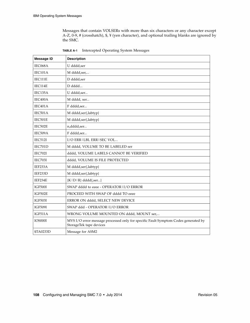
IBM Operating System Messages
108 Configuring and Managing SMC 7.0 • July 2014 Revision 05
Messages that contain VOLSERs with more than six characters or any character except A-Z, 0-9, # (crosshatch), $, ¥ (yen character), and optional trailing blanks are ignored by the SMC.
TABLE A-1 Intercepted Operating System Messages
Message ID Description
IEC068A U dddd,ser
IEC101A M dddd,ser,...
IEC111E D dddd,ser
IEC114E D dddd...
IEC135A U dddd,ser...
IEC400A M dddd, ser...
IEC401A F dddd,ser...
IEC501A M dddd,ser{,labtyp}
IEC501E M dddd,ser{,labtyp}
IEC502E n,dddd,ser...
IEC509A F dddd,ser...
IEC512I I/O ERR|LBL ERR|SEC VOL...
IEC701D M dddd, VOLUME TO BE LABELED ser
IEC702I dddd, VOLUME LABELS CANNOT BE VERIFIED
IEC703I dddd, VOLUME IS FILE PROTECTED
IEF233A M dddd,ser{,labtyp}
IEF233D M dddd,ser{,labtyp}
IEF234E {K|D|R} dddd{,ser...}
IGF500I SWAP dddd to eeee - OPERATOR|I/O ERROR
IGF502E PROCEED WITH SWAP OF dddd TO eeee
IGF503I ERROR ON dddd, SELECT NEW DEVICE
IGF509I SWAP ddd - OPERATOR|I/O ERROR
IGF511A WRONG VOLUME MOUNTED ON dddd, MOUNT ser,...
IOS000I MVS I/O error message processed only for specific Fault Symptom Codes generated by StorageTek tape devices
$TA0233D Message for ASM2

JES3 Messages
Revision 05 Appendix A Intercepted Messages 109
JES3 Messages The following JES3 messages are processed by the SMC:
■ IAT5210 ■ IAT5310 ■ IAT5410
IBM message manuals describe the exact format (spacing, etc.) and definition of each message.
Tape Management System Messages
CA-1 Messages The following CA-1 (TMS) messages are intercepted by the SMC. Refer to the appropriate Computer Associates publication for the exact format and meaning of each message.
TABLE A-2 Tape Management System Messages - CA-1
Message ID Description
CTS001 See CA-1 User Manual, Volume 1
CTS002 See CA-1 User Manual, Volume 1
CTS004 See CA-1 User Manual, Volume 1
CTS005 See CA-1 User Manual, Volume 1
CTS007 See CA-1 User Manual, Volume 1
CTS008 See CA-1 User Manual, Volume 1
CTS009 See CA-1 User Manual, Volume 1
CTS010 See CA-1 User Manual, Volume 1
CTS011 See CA-1 User Manual, Volume 1
CTS014 See CA-1 User Manual, Volume 1
CTS015 See CA-1 User Manual, Volume 1
CTT100A See CA-1 User Manual, Volume 1
CTT101A See CA-1 User Manual, Volume 1
CTT102A See CA-1 User Manual, Volume 1
CTT103A See CA-1 User Manual, Volume 1
CTT104A See CA-1 User Manual, Volume 1
CTT105A See CA-1 User Manual, Volume 1

Tape Management System Messages
110 Configuring and Managing SMC 7.0 • July 2014 Revision 05
CONTROL-M/TAPE (formerly CONTROL-T) MessagesThe following CONTROL-M/TAPE messages are intercepted by the SMC. Refer to the appropriate BMC publication for the exact format and meaning of each message.
TMS001 See CA-1 User Manual, Volume 1
TMS002 See CA-1 User Manual, Volume 1
TMS004 See CA-1 User Manual, Volume 1
TMS005 See CA-1 User Manual, Volume 1
TMS007 See CA-1 User Manual, Volume 1
TMS008 See CA-1 User Manual, Volume 1
TMS009 See CA-1 User Manual, Volume 1
TMS010 See CA-1 User Manual, Volume 1
TMS011 See CA-1 User Manual, Volume 1
TMS014 See CA-1 User Manual, Volume 1
TMS015 See CA-1 User Manual, Volume 1
IECTMS7 See CA-1 User Manual, Volume 1
CA$F810A See CA-1 Message Guide
CA$F813A See CA-1 Message Guide
TABLE A-3 CONTROL-M/TAPE Messages
Message ID Description
CTT100A See BMC’s INCONTROL for OS/390 and z/OS Message Manual
CTT101A See BMC’s INCONTROL for OS/390 and z/OS Message Manual
CTT102A See BMC’s INCONTROL for OS/390 and z/OS Message Manual
CTT103A See BMC’s INCONTROL for OS/390 and z/OS Message Manual
CTT104A See BMC’s INCONTROL for OS/390 and z/OS Message Manual
CTT105A See BMC’s INCONTROL for OS/390 and z/OS Message Manual
TABLE A-2 Tape Management System Messages - CA-1 (Continued)
Message ID Description

Tape Management System Messages
Revision 05 Appendix A Intercepted Messages 111
DFSMSrmm Messages DFSMSrmm mount message (EDG6627A) must be acted on by the SMC when the volume or drive specified in the message is under the control of the SMC. The action of the SMC is similar to the SMC actions for the normal MVS mount messages (e.g., IEC233A, etc).
The DFSMSrmm Tape Initialization program (EDGINERS) issues a series of messages describing the success or failure of tape initialization, erasure, and/or verification. This series of messages is used to drive the dismount of the tapes mounted from the EDG6627A message. The following messages must be acted on by the SMC to dismount a tape:
TABLE A-4 Tape Management System Messages - DFSMSrmm
Message ID Description
EDG6620I VOLUME volser INITIALIZATION AND VERIFICATION SUCCESSFUL
EDG6621E VOLUME volser INITIALIZATION FAILED
EDG6623I VOLUME volser ERASE, INITIALIZATION AND VERIFICATION SUCCESSFUL
EDG6624I VOLUME volser ERASE FAILED
EDG6627E M dev VOLUME (volser) RACK (rack-number) TO BE action, lbltype
EDG6642E VOLUME volser LABELLED SUCCESSFULLY
EDG6643E VOLUME volser ERASED AND LABELLED SUCCESSFULLY

Tape Management System Messages
112 Configuring and Managing SMC 7.0 • July 2014 Revision 05

Revision 05 113
APPENDIX
B
SMC Interaction with Other Software
Automated OperationsCustomers who use an automated operations product should review WTOR SMC0110, issued during SMC swap processing, for possible auto-ops rule changes.
CA-MIA Tape SharingThe Computer Associates Unicenter CA-MIA Tape Sharing for z/OS relies upon direct modification of the EDL at SSI24 time to determine what tape drives remain eligible for an allocation event. However, the SMC does not directly modify the EDL as part of its normal allocation processing. To enable proper coexistence with CA-MIA Tape Sharing, set the MIAcompat parameter of the ALLOCDef command to ON.
CA1-RTS Real Time StackingThe Computer Associates Real Time Stacking product relies on DEFER processing being performed at SSI24 time. However, the SMC normally performs DEFER processing during SSI78 time. To enable proper coexistence with CA1-RTS, set the CA1rts parameter of the ALLOCDef command to ON.

CA-Vtape
114 Configuring and Managing SMC 7.0 • July 2014 Revision 05
CA-VtapeThe Computer Associates CA-Vtape supplies user exits 02 and 08 for the SMC that activate and enable CA-Vtape processing. Normally, user exits 02 and 08 will not be called if an applicable SMC POLICY object applies to the allocation event. There are several alternatives to ensure that the CA-Vtape supplied user exits are invoked:
■ Do not specify a default SMC TAPEREQ statement in your SMC TREQDEF definitions file. If no default SMC TAPEREQ statement is found, and if all other TAPEREQs target specific SMC controlled allocation events, then the supplied user exits will be called to determine if the non-SMC controlled allocation events are to be directed to CA-Vtape.
■ If you do specify a default SMC TAPEREQ statement, use the legacy TAPEREQ definitions to define the tape policy and do not direct the default TAPEREQ definition to a POLICY object. Thus, if your default TAPEREQ statement is to specify virtual media, then specify the last TAPEREQ statement as:TAPEREQ JOB(*) MEDIA VIRTUAL
instead of:
TAPEREQ JOB(*) POLICY VIRTPOL
where policy VIRTPOL specifies MEDIA VIRTUAL.
■ Specify ALLOCDef CAVTAPe(ON) in either your SMCCMDS or SMCPARMS data set at startup. When ALLOCDef CAVTAPe(ON) is specified, then user exits 02 and 08 are called even when an applicable SMC POLICY object applies to the allocation event.

Fault Analyzer for z/OS
Revision 05 Appendix B SMC Interaction with Other Software 115
Fault Analyzer for z/OSThe IBM program Fault Analyzer for z/OS is used to determine why an application abends. It may be installed on systems that also run StorageTek ELS software products, however, it is not useful when applied to abends that occur in ELS code. Because of the complex subsystem environment where ELS code executes, Fault Analyzer itself may abend.
If Fault Analyzer for z/OS is installed on your ELS system, it is strongly recommended that you specify the following update to ensure that this product ignores ELS product abends.
When Fault Analyzer is installed, perform the following update to SYS1.PARMLIB(IDICNF00):EXCLUDE (NAME(HSC) NAME(SMC) NAME(CSC))
where:
■ HSC is the name of the HSC console-started-task.■ SMC is the name of the SMC console-started-task.■ CSC is the name of the MVS/CSC console-started-task.
Alternatively, you can specify EXCLUDE (TYPE(STC)) to exclude all console-started tasks from evaluation by Fault Analyzer. However, this broad exclusion may not be appropriate in your environment.
MVS Security PackagesEnsure that your MVS security package (e.g., RACF, TopSecret) is configured to grant SMC the necessary authority to respond to MVS swap messages.

Open Type J
116 Configuring and Managing SMC 7.0 • July 2014 Revision 05
Open Type JThe Open Type J macro is not supported during SMC message handling processing.
Additionally, SMC allocation enhancements may not operate if you use the MVS Open Type J macro. Because this macro allows you to change volume serial numbers or data set names at open time, information available at Job Step Allocation time may be incorrect as interpreted by the SMC.
Note – Some vendor software products use MVS Open Type J. If you are experiencing unexpected allocation results using a vendor software product, check with the vendor to determine if Open Type J is used and follow the recommendations below.
SMC allocation may influence MVS allocation erroneously based on information that may have changed at open time. To prevent this problem when using the Open Type J macro, specify the appropriate esoteric in the JCL or specify an appropriate esoteric in an applicable TAPEREQ control statement or POLicy command.
SAMS: DISK (DMS) Sterling Software’s SAMS: DISK (DMS) has two methods of allocating transports:
■ Allocates transports at session startup, holds onto the transports throughout the session and uses Open Type J (see page 116)
■ Uses dynamic allocation (DYNALLOC) to allocate transports when required
The SMC allocates correctly when dynamic allocation is used. Therefore, the latter method of allocating transports is recommended.

Revision 05 117
Glossary
This glossary defines terms and abbreviations used in this publication.
AAbnormal end of task (abend) A software or hardware problem that terminates a computer processing task.
ACS-id A method used in the LIBGEN process to identify ACSs by using hexadecimal digits, 00 to nn.
ACS See Automated Cartridge System.
ACS library A library is composed of one or more Automated Cartridge Systems (ACSs), attached cartridge drives, and cartridges residing in the ACSs.
address Coded representation of hardware id, or the destination or origination of data.
allocation The assignment of resources to a specific task.
asynchronous transmission Character-oriented data transmission (as distinct from IBM’s block-mode transmission).
Automated Cartridge System (ACS) A fully-automated, cartridge storage and retrieval library subsystem consisting of one or more Library Storage Modules (LSMs) connected by pass-thru ports.
Automated Cartridge System Library Software (ACSLS) The library control software, which runs in the UNIX®-based Library Control System.
automatic mode A relationship between an LSM and all attached hosts. LSMs operating in automatic mode handle cartridges without operator intervention. This is the normal operating mode of an LSM that has been modified online. The opposite situation is “manual mode.” See manual mode.

118 Configuring and Managing SMC 7.0 • July 2014 Revision 05
Bbar code A code consisting of a series of bars of varying widths. This code appears on the external label attached to the spine of a cartridge and is equivalent to the volume serial number (volser). This code is read by the robot’s machine vision system.
BISYNC Binary Synchronous Communications. An early low-level protocol developed by IBM and used to transmit data on a synchronous communications link. It is a form of data transmission in which synchronization of characters is controlled by timing signals generated at the sending and receiving stations.
CCAPid A CAPid uniquely defines the location of a CAP by the LSM on which it resides. A CAPid is of the form “AAL” where “AA” is the acs-id and “L” is the LSM number.
cartridge The plastic housing around the tape. It is approximately 4 inches (100 mm) by 5 inches (125 mm) by 1 inch (25 mm). The tape is threaded automatically when loaded in a transport. A plastic leader block is attached to the tape for automatic threading. The spine of the cartridge contains an OCR/Bar Code label listing the VOLSER (tape volume identifier).
Cartridge Access Port (CAP) An assembly that allows several cartridges to be inserted into or ejected from an LSM without human entry into the LSM.
cartridge drive (CD) A hardware device containing two or four cartridge transports and associated power and pneumatic supplies.
cartridge tape I/O driver Operating system software that issues commands (for example, read, write, and rewind) to cartridge subsystems. It is the software focal point for attaching a particular type of control unit. (An example is Oracle’s StorageTek CARTLIB product.)
cartridge transport See transport.
cell A receptacle in the LSM in which a single cartridge is stored.
CGI Common Gateway Interface
channel A device that connects the host and main storage with the input and output devices’ control units. A full-duplex channel has two paths (that is, 2 wires, or one wire with signals at two frequencies). A half-duplex channel requires that one port receives while the other transmits.
channel-to-channel (CTC) Refers to the communication (transfer of data) between programs on opposite sides of a channel-to-channel adapter.(I)
client The ultimate user of the ACS services as provided by the Library Control System.
client link The communications link between the LCS and a client.

Revision 05 Glossary 119
client-server A model of interaction in a distributed system in which a program at one site serves a request to a program at another site and awaits a response. The requesting program is called a client; the program satisfying the request is called a server.
client system The system to which the LCS provides an interface to a StorageTek Automated Cartridge System.
Client System Component (CSC) Software that provides an interface between the Client Computing System’s operating system and the StorageTek Library Control System (LCS).
coaxial cable A transmission medium used in data transmissions for networks using synchronous communications, as opposed to twisted-pair, the primary medium for asynchronous RS-232 communications.
complex A system composed of other systems, specifically the ACS server system and the client system.
connected mode A relationship between a host and an ACS. In this mode, the host and an ACS are capable of communicating (in the sense that at least one station to this ACS is online).
connection number The unique identifier on the server for a communications path. The number is assigned by TCP/IP to identify the unique connection between the server node and a specific port on the server, and the client node and a specific port on the client. The connection number exists only as long as the connection exists.
console The primary I/O device to control a session on a system.
control data set (CDS) The data set used by the host software to control the functions of the automated library. Also called a library database.
Control Path Adaptor (CPA) A Bus-Tech, Inc. hardware device that allows communications between a host processor’s block multiplexer channel and a local area network.
Control Unit (CU) A microprocessor-based unit situated locally between a channel and an I/O device. It translates channel commands into device commands and sends device status to the channel.
coupling facility A special logical partition that provides high-speed caching, list processing, and locking functions in a sysplex.(I)
coupling facility channel A high bandwidth fiber optic channel that provides the high-speed connectivity required for data sharing between a coupling facility and the central processor complexes directly attached to it.(I)
CTC Channel-to-channel.
Data Path Adapter A hardware device which translates from a client computing system’s data protocol to the data protocol of the StorageTek Control Unit or IMU. An example is DEC’s TC44-AA/BA STI-to-4400 ACS Interconnect.
120 Configuring and Managing SMC 7.0 • July 2014 Revision 05
Ddata set A set of records treated as a unit.
data sharing The ability of concurrent subsystems or application programs to directly access and change the same data while maintaining data integrity.(I)
device number A four-digit hexadecimal number that uniquely identifies a device attached to a processor.
device preferencing The process of preferring one 36-track transport type over another 36-track transport type.
device separation See drive exclusion.
DFSMS Data Facility Storage Management Subsystem.
direct access storage device (DASD) IBM’s term for a disk drive storage device.
directed allocation See drive prioritization.
disconnected mode A relationship between a host and an ACS. In this mode, the host and the ACS are not capable of communicating (there are no online stations to this ACS).
dotted-decimal notation The syntactic representation of a 32-bit integer that consists of four 8-bit numbers written in base ten with periods (dots) separating them. In TCP/IP descriptions, dotted-decimal notation is used for Internet addresses.
drive exclusion (previously referred to as device separation) refers to the SMC function of excluding drives for an allocation request based on SMC exclusion criteria.
drive panel An LSM wall containing tape transports. The drive panel for a T9840 transport can contain either 10 or 20 transports. The drive panel for a non-T9840 transport can contain a maximum of 4 transports.
drive prioritization (previously referred to as directed allocation) refers to the SMC function of influencing selection of a particular drive based on allocation criteria, including volume location.
Dual LMU A hardware/microcode feature that provides a redundant LMU capability.
dump A printed representation of the contents of main storage at time t. This representation is used for debugging purposes.
dynamic server switching The capability of switching server processors when a system failure occurs on the active server.

Revision 05 Glossary 121
EECART Enhanced Capacity Cartridge.
Enhanced Capacity Cartridge A cartridge that has a length of 1100 feet and can be used only on 36-track transports (i.e., 4490, 9490, and 9490EE).
Enterprise Systems Connection (ESCON) A set of products and services that provides a dynamically connected environment using optical cables as a transmission medium.(I)
error codes (EC) Numeric codes displayed by messages indicating the type of problem that caused an error.
error recovery procedures (ERP) Procedures designed to help isolate and, where possible, to recover from errors in equipment.
ESCON Enterprise Systems Connection.
esoteric name The name assigned to transports that have the same device type.
Ethernet One LAN architecture using a bus topology that allows a variety of computers to be connected to a common shielded coaxial spine. The Ethernet architecture is similar to the IEEE 802.3 standard.
event control block (ECB) Provides an area for a completion code to be stored when an operation has completed.
Ffile A set of related records treated as a unit.
File Transfer Protocol (FTP) A TCP/IP command that provides a way to transfer files between machines connected through TCP/IP.
foreign socket One of two end-points in a TCP/IP connection-oriented protocol. Specifies the address of a foreign host that can connect to the server.
GGB 1,073,741,834 bytes of storage

122 Configuring and Managing SMC 7.0 • July 2014 Revision 05
Hhandshake A flow-of-control signal sent by one process to another.
helical cartridge A high capacity, helical scan cartridge that can hold up to 50GB of uncompressed data. This cartridge can be used only on RedWood (SD-3) transports.
host computer A computer that controls a network of computers.
Host Software Component utilities Utilities provided by the VM/HSC that can be executed from the HSCUTIL virtual machine. See client-initiated utilities.
HTTP Hypertext Transfer Protocol.
IIEEE 802.3 A standard produced by the IEEE and accepted worldwide for local area networks using CSMA/CD (Carrier Sense Multiple Access with Collision Detection).
ICRC Improved Cartridge Recording Capacity. A compression and compaction feature that increases the amount of data that can be stored on a 1/2-inch cartridge.
initial program load (IPL) A process that activates a machine reset.
Interactive Storage Management Facility A series of applications for defining DFSMS/MVS storage groups and classes.
Internet A collection of networks using TCP/IP that functions as a virtual network.
Internet address The numbering system used to specify a network or host on that network for TCP/IP communications. Standard Internet address notation is dotted-decimal format.
Internet Protocol (IP) Formal description of messages and rules two networks use to exchange messages.
ISMF Interactive Storage Management Facility.

Revision 05 Glossary 123
Jjob control language (JCL) A problem oriented language designed to describe a job’s processing requirements to an operating system.
JES Job entry subsystem.(I)
JES2 An MVS subsystem that receives jobs into the system, converts them to internal format, selects them for execution, processes their output, and purges them from the system. In an installation with more than one processor, each JES2 processor independently controls its job input, scheduling, and output processing. See also JES3.(I)
JES3 An MVS subsystem that receives jobs into the system, converts them to internal format, selects them for execution, processes their output, and purges them from the system. In complexes that have several loosely coupled processing units, the JES3 program manages processors so that the global processor exercises centralized control over the local processors and distributes jobs to them via a common job queue. See also JES2.(I)
LLAN See local area network.
LCS See Library Control System.
LCS processor console The Library Control System processor console is used to control the VM operating system (for the VM-based LCS).
LCU See Library Control Unit.
LIBGEN The process of defining the configuration of a library to the VM/HSC.
library See TapePlex.
library cartridge transport See transport.
library complex A library complex consists of one HSC Control Data Set (CDS) and may contain up to 256 Automatic Cartridge Systems (ACSs), each of which may contain up to 24 Library Storage Modules (LSMs).
library control component Software that controls the mounting and dismounting of cartridges in an ACS.
library control platform The hardware and software that provides the proper environment for the Library Control System.
library control processor Properly configured computer hardware that supports the operation of the Library Control System.
Library Control Software A library control component, the client system interface, and library utilities.
Library Control System (LCS) The library control platform and the Library Control Software.
124 Configuring and Managing SMC 7.0 • July 2014 Revision 05
Library Control Unit (LCU) The portion of an LSM that controls the movements of the robot.
library database A file or data set containing information about the location and status of the removable media volumes, such as cell location, scratch status. Also called a control data set (CDS).
library drive A cartridge drive in the ACS, as distinct from a stand-alone cartridge drive.
Library Management Unit (LMU) A hardware and software product that coordinates the activities of one or more LSMs/LCUs.
library mode The operation of a 4480 Cartridge Subsystem as part of a 4400 Automated Cartridge System, as opposed to manual mode, in which the operator inserts cartridges into the transports. See manual mode.
Library Storage Module (LSM) The standard LSM (4410) a twelve-sided structure with storage space for up to around 6000 cartridges. It also contains a free-standing, vision-assisted robot that moves the cartridges between their storage cells and attached transports. See also PowderHorn, SL3000, SL8500, and WolfCreek.
LMU See Library Management Unit.
local area network (LAN) A network in a small (local) geographic area.
local port The designation of a given application or process among many that are available for a TCP/IP-capable host processor.
local socket The address combination of a TCP/IP-capable host’s network address and a specific port for an application process.
logical port (LP) CLS software that interfaces with the client system. The CLSLP is one of the software components used to pass data between the client system and the VM/HSC.
LP See logical port.
LSM See Library Storage Module.
LSM-id An LSM-id is composed of the ACS-id joined to (concatenated with) the LSM number.
LSM number A method used to identify an LSM. An LSM number is the result of defining the SLIACS macro LSM parameter during a LIBGEN. The first LSM listed in this parameter acquires the LSM number of 00 (hexadecimal) the second LSM listed acquires a number of 01, and so forth, until all LSMs are identified (up to a maximum of 24 or hexadecimal 17).
Revision 05 Glossary 125
Mmanual mode Operation of a cartridge drive apart from an ACS. See library mode.
master LMU The LMU currently controlling the functional work of the ACS in a dual LMU configuration.
mixed configuration A configuration that contains different types of cartridge drives in both manual and library modes.
modem A device that enables digital data to be transmitted over an analog transmission facility.
multi-client The environment where more than one (homogenous or heterogeneous) client system is connected to one LCS.
MVS system console The MVS/CSC provides an operator interface through the MVS system console.
OOCR label Optical character recognition label. An external label attached to the spine of a cartridge that is both human and machine readable.
operator console In this document, the operator console refers to the MVS client system console.
operating system (OS) Software that controls the execution of programs that facilitate overall system operation.
126 Configuring and Managing SMC 7.0 • July 2014 Revision 05
PPass-thru Port (PTP) A mechanism that allows a cartridge to be passed from one LSM to another in a multiple LSM ACS.
physical port The communications hardware required to support a server/client link.
physical volume A physically bound unit of data file media. See cartridge.
PowderHorn (9310) The high-performance version of the standard LSM.
pre-configured package A storage server package including all hardware, software, and configuration parameter settings delivered by the vendor.
product change request (PCR) A request for enhancement to a product. Normally, this request comes from a client, but may come from Oracle.
program temporary fix (PTF) A software release designed to remedy one or a series of defects.
program update tape (PUT) One or more tapes containing updates to, or new versions of, the MVS/CSC system software.
protocol A formal description of message formats and the rules two or more machines must follow to exchange these messages.
Rrecovery Automatic or manual procedures to resolve problems in the server system.
reel-id Identifier of a specific tape volume. Equivalent to volume serial number (VOLSER).
request Term used to refer to commands issued to the 4400 ACS to perform a tape-related function.

Revision 05 Glossary 127
Sscratch tape A tape that is available to any user because it is not owned.
scratch tape subpool A defined subset of all scratch tapes. Subpools are composed of one or more ranges of volsers with similar physical characteristics (type of volume—reel or cartridge, reel size, length, physical location, and so on). Some installations may also subdivide their scratch pools by other characteristics such as label type.
SD-3 The StorageTek helical cartridge transport. Also known as RedWood.
server An ELS library control system such as HSC. In SMC a server is represented by a named SERVER path to a named TAPEPLEX. While the SMC HTTP server component is required as the middle ware on the remote host, the server, as far as SMC is concerned is the ELS library control system operating on the remote host.
socket A unique address on a network plus a node address plus the id of one specific application on a specific network. An abstraction used by TCP/IP.
standard capacity cartridge A cartridge that can be used on any longitudinal transport (i.e., 4480, 4490, 9490, or 9490EE).
standby The status of a station that has been varied online but is connected to the standby LMU of a dual LMU ACS.
standby LMU The redundant LMU in a dual LMU configuration that is ready to take over in case of a Master LMU failure or when the operator issues a SWITCH command.
station A hardware path between the host computer and an LMU over which the VM/HSC and LMU send control information.
storage server A set of hardware and software products designed to enable heterogeneous computer systems to use automated tape cartridge library services.
Storage Management Component (SMC) Software interface between IBM’s z/OS operating system and StorageTek automated library control systems, HSC and MVS/CSC. SMC performs the allocation processing, message handling, and SMS processing for the ELS solution.
switchover The assumption of master LMU function by the standby LMU.
synchronous See BISYNC.
synchronous LAN Local area network built on synchronous communications.
Systems Network Architecture (SNA) A description of the logical structure, formats, protocols, and operational sequences for transmitting information units through and controlling the configuration and operation of networks.
128 Configuring and Managing SMC 7.0 • July 2014 Revision 05
Ttape drive A tape processing device consisting of up to four transports in a cabinet. A drive can refer to an individual transport.
tape library management system (TLMS) TLMS, as used in this document, refers to any tape library management system, not to CA-1.
TapePlex (formerly “library”), a single StorageTek hardware configuration, normally represented by a single HSC Control Data Set (CDS). A TapePlex may contain multiple Automated Cartridge Systems (ACSs) and Virtual Tape Storage Subsystems (VTSSs).
TCP/IP Transmission Control Protocol/Internet Protocol.
trace event type Types of event traced through the system when tracing is enabled.
trace file A file that contains information useful for debugging the system.
transaction A specific set of input that triggers the execution of a specific process.
Transmission Control Protocol (TCP) An inter-network standard protocol that provides a full-duplex stream service.
transport An electro-mechanical device used to thread, position, and read or write from a tape.
UUCB Unit Control Block.
userid Sometimes referred to as the VM userid, the userid is the name that identifies a specific “virtual machine” user or client.
utility Program that performs a function ancillary to the chief function(s) of a computer system.

Revision 05 Glossary 129
Vvirtual machine (VM) A functional simulation of a computer and its associated devices. Each virtual machine is controlled by a suitable operating system.
virtual storage A feature of the OS where main storage requirements are allocated by segments (or pages) as needed by programs, thus creating the apparent existence of unlimited or virtual storage.
Virtual Storage Manager (VSM) A storage solution that virtualizes volumes and transports in a VTSS buffer in order to improve media and transport use.
Virtual Tape Control System (VTCS) The primary host code for the Virtual Storage Manager (VSM) solution. This code operates in a separate address space, but communicates closely with HSC.
Virtual Tape Storage Subsystem (VTSS) The DASD buffer containing virtual volumes (VTVs) and virtual drives (VTDs). The VTSS is a StorageTek RAID 6 hardware device with microcode that enables transport emulation. The RAID device can read and write “tape” data from/to disk, and can read and write the data from/to a real tape drive (RTD).
Virtual Telecommunications Access Method (VTAM) IBM host-resident communications software that serves as a common interface for communications.
VM See virtual machine.
VM/SP or VM/XA A proprietary operating system of IBM corporation that consists mainly of two major components, CP and CMS.
volume A tape cartridge (data carrier) that is mounted or dismounted as a unit.
volume serial number (VOLSER) An identifier of a physical volume.
WWolfCreek (9360) The high-performance LSM with a smaller capacity than the standard LSM.
ZZCART An extended-enhanced cartridge that uses a thinner media to provide twice the capacity of the enhanced capacity (ECART) cartridge. This cartridge has a length of 2200 feet and can be used only on TimberLine 9490EE 36-track transports.

130 Configuring and Managing SMC 7.0 • July 2014 Revision 05
Numerics802.3 See IEEE 802.3.
3270 IBM synchronous, block-mode, half-duplex terminals preferred for use with IBM 370 and related types of machine.
3270 protocol A telecommunications protocol that supports networks of 327x CRTs on IBM mainframes.
3274 Terminal control unit used on the ACS for processor-to-LMU communications.
3480 IBM’s 18-track half-inch cartridge tape drive model.
3490 IBM’s 36-track half-inch cartridge tape drive model.
3590 IBM’s newest cartridge tape drive model that supports 128-track recording technique.
4400 Automated Cartridge System (ACS) A fully automated, cartridge-based, 18-track storage and retrieval library. A 4400 ACS consists of 1 to 256 LMUs with each LMU connected to from 1 to 24 LSMs.
4410 The standard Library Storage Module (LSM).
4411 Library Control Unit (LCU).
4480 The StorageTek 18-track 1/2-inch cartridge transport.
4480 Cartridge Subsystem The StorageTek 4480 Cartridge Subsystem consists of a control unit (CU) plus cartridge drives (CDs).
4490 The StorageTek 36-track long-tape cartridge transport with ESCON support. Also known as Silverton.
4780 Same as a 4480, but is used for attachment to certain non-IBM computers.
8380 The StorageTek DASD system.
9310 The PowderHorn, a high-performance version of the standard LSM (4410)
9360 The WolfCreek, a high-performance LSM with a smaller capacity than the standard LSM (4410).
9490 The StorageTek 36-track cartridge transport. Also known as TimberLine.
9490EE The StorageTek 36-track cartridge transport. Also known as TimberLine EE.
9740 A small, four-sided StorageTek library that supports large-style cartridge transports. This library can be configured to contain either 326 cartridges or 494 cartridges.
SL3000 The StorageTek high performance library scalable from 200 to 3,000 cartridge slots.
SL8500 The StorageTek high performance library scalable from 29 terabytes to 70 petabytes with up to 70,000 tape slots.
T9840A The StorageTek access-centric cartridge transport capable of reading and writing 9840A cartridges.

Revision 05 Glossary 131
T9840B The StorageTek access-centric cartridge transport capable of reading and writing T9840B cartridges.
T9840C The StorageTek access-centric cartridge transport capable of reading and writing T9840C cartridges.
T9840D The StorageTek access-centric cartridge transport capable of reading and writing T9840D cartridges.
T9940A The StorageTek capacity-centric cartridge transport capable of reading and writing 60GB T9940A cartridges.
T9940B The StorageTek capacity-centric cartridge transport capable of reading and writing 200GB T9940B cartridges.
T10000 The StorageTek high-capacity cartridge transport capable of reading and writing 120GB or 500GB T10000 cartridges.
T10000B The StorageTek high-capacity cartridge transport capable of reading and writing 240GB or 1TB T10000 cartridges.
T10000C The StorageTek high-capacity cartridge transport capable of reading and writing 1TB or 5TB T10000C cartridges.
T10000D The StorageTek high-capacity cartridge transport capable of reading and writing 1.6TB or 8TB T10000D cartridges.

132 Configuring and Managing SMC 7.0 • July 2014 Revision 05

Revision 05 1
Index
Aaffinity separation, 73allocation
JES2, 76JES3, 78
CCA-1 (TMS) messages, 109client communication monitor subtask, 35client/server drive address mapping, 43client/server feature
client communication monitor subtask, 35communication considerations, 34defining server paths, 35overview, 34SMC http server component, 36
configuration scenariossingle TapePlex using the SMC Client/Server
feature, 39single TapePlex with SMC and HSC on the same
host, 38two TapePlexes accessed by a single SMC, 41
conventionscontrol statements, 19typographic, 15
Ddeferring mounts, 75defining server paths, 35description, SMC, 21DEVICE initialization statements, JES3, 84DFSMS processing
ACS routine environment, 60enabling and disabling, 57MGMTCLAS considerations, 61overview, 57STORCLAS and MGMTCLAS specification, 58tailoring, 57
DFSMSrmm messages, 111drive exclusion
overview, 67
scratch request, 70specific request, 68virtual scratch request, 72
drive prioritization, 74drive type information synchronization, 44
Eesoteric name replacement, JES3, 80esoteric substitution
at IDAX, 53examples
JES3 high watermark setup, 93exceptions, SMC allocation, 75exclusion levels
scratch request, 70specific request, 68
EXEC Statement, SMC, 28
FFault Analyzer for z/OS, SMC interaction with, 115fetch messages, suppressing in JES3, 82
HHTTP server component
displaying status, 36overview, 36starting and stopping, 36
HWSNAME statements, JES3, 87
IIBM (International Business Machines, Inc.)
operating system messages, 107IDAX
and SMC Policy, 52esoteric substitution, 53
initialization, SMC, 23intercepted messages
IBM operating system messages, 107JES3 messages, 109tape management system messages, 109
introduction, SMC, 21

2 Configuring and Managing SMC 7.0 • July 2014 Revision 05
JJES2 allocation, 76JES3
allocation, 78Converter/Interpreter (C/I), 79Main Device Scheduler (MDS), 79
Llibrary control server, and SMC, 33
Mmessage handling, SMC, 95messages
DFSMSrmm messages, 111HSC mount-related messages, 99intercepted, 107messages intercepted by HSC, 107tape management system messages, 109
mounts, managing from the SMC client, 99MVS START Command, 31
Pparameters
SMC EXEC Statement, 28policy
and esoteric preferencing, 51and the TAPEREQ control statement, 54at IDAX, 52defining using the SMC POLicy command, 50example, 56
Rrecovery procedures, 101region size considerations, 36
Sscratch subpool 0, 70SETNAME statements, JES3, 85SMC
allocation, 65configuration scenarios, 37DFSMS processing, 57drive address mapping, 43drive exclusion, 67drive prioritization, 74functions, 21initializing, 23interaction with other software, 113message handling, 95normal operations, 91policy, 49policy and drive type information
synchronization, 44recovery procedures, 101starting, 23
TapePlex subsystem selection, 47SMCCMDS data set, 26SMCLOG data set, 27SMCPARMS data set, 26SSI23 dynamic allocation, 79SSI24 allocation, 79SSI24 common allocation, 76SSI55 (IDAX), 76, 78SSI78 allocation, 77START Command, MVS, 31START procedure
creating, 25SMCLOG data set, 27SMCPARMS and SMCCMDS data sets, 26
starting SMC, 23swap processing, SMC, 98syntax
SMC EXEC Statement, 28
TTape Management System (TMS)
messages, 109supported, 97
TapePlex selection, 47TapePlex, defining for SMC, 34TAPEREQ control statement
and SMC Policy, 54
UUNITAttr command, specifying drive type
information, 44
Vvolume serial numbers, defined, 107
ZZEROSCR considerations, 90