Configure SR-TE Policies...ConfigureSR-TEPolicies...
14
Configure SR-TE Policies This module provides information about segment routing for traffic engineering (SR-TE) policies, how to configure SR-TE policies, and how to steer traffic into an SR-TE policy. Configuring SR-TE policies with 3 or more labels and an L2 Transport Interface on the same network processing unit (NPU) can cause traffic loss. Note • Limitations, on page 1 • Configure SR-TE Policies , on page 1 • BGP SR-TE, on page 4 • Configure Interface TE Metrics, on page 7 • Configure Named Interface Link Admin Groups and SR-TE Affinity Maps, on page 7 • Using Binding Segments, on page 9 Limitations Observe the following limitations for the platform. Configure SR-TE Policies Segment routing for traffic engineering (SR-TE) uses a “policy” to steer traffic through the network. An SR-TE policy path is expressed as a list of segments that specifies the path, called a segment ID (SID) list. Each segment is an end-to-end path from the source to the destination, and instructs the routers in the network to follow the specified path instead of following the shortest path calculated by the IGP. If a packet is steered into an SR-TE policy, the SID list is pushed on the packet by the head-end. The rest of the network executes the instructions embedded in the SID list. An SR-TE policy is identified as an ordered list (head-end, color, end-point): • Head-end – Where the SR-TE policy is instantiated • Color – A numerical value that distinguishes between two or more policies to the same node pairs (Head-end – End point) • End-point – The destination of the SR-TE policy Configure SR-TE Policies 1
Transcript of Configure SR-TE Policies...ConfigureSR-TEPolicies...
Configure SR-TE Policies
This module provides information about segment routing for traffic engineering (SR-TE) policies, how toconfigure SR-TE policies, and how to steer traffic into an SR-TE policy.
Configuring SR-TE policies with 3 or more labels and an L2 Transport Interface on the same network processingunit (NPU) can cause traffic loss.
Note
• Limitations, on page 1• Configure SR-TE Policies , on page 1• BGP SR-TE, on page 4• Configure Interface TE Metrics, on page 7• Configure Named Interface Link Admin Groups and SR-TE Affinity Maps, on page 7• Using Binding Segments, on page 9
LimitationsObserve the following limitations for the platform.
Configure SR-TE PoliciesSegment routing for traffic engineering (SR-TE) uses a “policy” to steer traffic through the network. AnSR-TE policy path is expressed as a list of segments that specifies the path, called a segment ID (SID) list.Each segment is an end-to-end path from the source to the destination, and instructs the routers in the networkto follow the specified path instead of following the shortest path calculated by the IGP. If a packet is steeredinto an SR-TE policy, the SID list is pushed on the packet by the head-end. The rest of the network executesthe instructions embedded in the SID list.
An SR-TE policy is identified as an ordered list (head-end, color, end-point):
• Head-end – Where the SR-TE policy is instantiated
• Color – A numerical value that distinguishes between two or more policies to the same node pairs(Head-end – End point)
• End-point – The destination of the SR-TE policy
Configure SR-TE Policies1

Every SR-TE policy has a color value. Every policy between the same node pairs requires a unique colorvalue.
An SR-TE policy uses one or more candidate paths. A candidate path is a single segment list (SID-list) or aset of weighted SID-lists (for weighted equal cost multi-path [WECMP]). A candidate path is either dynamicor explicit.
A dynamic path is based on an optimization objective and a set of constraints. The head-end computes asolution, resulting in a SID-list or a set of SID-lists. When the topology changes, a new path is computed. Ifthe head-end does not have enough information about the topology, the head-endmight delegate the computationto a Segment Routing Path Computation Element (SR-PCE). For information on configuring SR-PCE, seeConfigure Segment Routing Path Computation Element chapter.
An explicit path is a specified SID-list or set of SID-lists.
An SR-TE policy initiates a single (selected) path in RIB/FIB. This is the preferred valid candidate path.
A candidate path has the following characteristics:
• It has a preference – If two policies have same {color, endpoint} but different preferences, the policywith the highest preference is selected.
• It is associated with a single binding SID (BSID) – A BSID conflict occurs when there are different SRpolicies with the same BSID. In this case, the policy that is installed first gets the BSID and is selected.
• It is valid if it is usable.
A path is selected when the path is valid and its preference is the best among all candidate paths for that policy.
The protocol of the source is not relevant in the path selection logic.Note
Configuration Example
To configure a local SR-TE policy, you must complete the following configurations:
1. Create the segment lists.
2. Create the policy.
Configure Local SR-TE Policy
/* Enter the global configuration mode and create the SR-TE segment lists */Router# configureRouter(config)# segment-routingRouter(config-sr)# traffic-engRouter(config-sr-te)# segment-list name Plist-1Router(config-sr-te-sl)# index 1 mpls label 400102Router(config-sr-te-sl)# index 2 mpls label 400106Router(config-sr-te-sl)# exit
Router(config-sr-te)# segment-list name Plist-2Router(config-sr-te-sl)# index 1 mpls label 400222Router(config-sr-te-sl)# index 2 mpls label 400106Router(config-sr-te-sl)# exit
/* Create the SR-TE policy */
Configure SR-TE Policies2
Configure SR-TE PoliciesConfigure SR-TE Policies

Router(config-sr-te)# policy P1Router(config-sr-te-policy)# binding-sid mpls 15001Router(config-sr-te-policy)# color 1 end-point ipv4 6.6.6.6Router(config-sr-te-policy)# candidate-pathsRouter(config-sr-te-policy-path)# preference 10Router(config-sr-te-pp-index)# explicit segment-list Plist-1Router(config-sr-te-pp-info)# weight 2Router(config-sr-te-pp-info)# exit
Router(config-sr-te-pp-index)# explicit segment-list Plist-2Router(config-sr-te-pp-info)# weight 2Router(config-sr-te-pp-info)# commitRouter(config-sr-te-pp-info)# endRouter(config)#
Running Configuration
Router# show running-configurationsegment-routingtraffic-engsegment-list name Plist-1index 1 mpls label 400102index 2 mpls label 400106!segment-list name Plist-2index 1 mpls label 400222index 2 mpls label 400106!policy P1binding-sid mpls 15001color 1 end-point ipv4 6.6.6.6candidate-pathspreference 10explicit segment-list Plist-1weight 2!explicit segment-list Plist-2weight 2!!!!!!
Verification
Router# show segment-routing traffic-eng policy name srte_c_1_ep_6.6.6.6Sat Jul 8 12:25:34.114 UTCSR-TE policy database---------------------Name: P1 (Color: 1, End-point: 6.6.6.6)Status:Admin: up Operational: up for 00:06:21 (since Jul 8 12:19:13.198)
Candidate-paths:Preference 10:Explicit: segment-list Plist-1 (active)Weight: 2400102 [Prefix-SID, 2.1.1.1]
Configure SR-TE Policies3
Configure SR-TE PoliciesConfigure SR-TE Policies

400106Explicit: segment-list Plist-2 (active)Weight: 2400222 [Prefix-SID, 22.11.1.1]400106
Attributes:Binding SID: 15001Allocation mode: explicitState: programmedPolicy selected: yes
Forward Class: 0
BGP SR-TESR-TE can be used by data center (DC) operators to provide different levels of Service Level Assurance(SLA). Setting up SR-TE paths using BGP (BGP SR-TE) simplifies DC network operation without introducinga new protocol for this purpose.
Explicit BGP SR-TE
Explicit BGP SR-TE uses an SR-TE policy (identified by a unique color ID) that contains a list of explicitpaths with SIDs that correspond to each explicit path. A BGP speaker signals an explicit SR-TE policy to aremote peer, which triggers the setup of an SR-TE policy with specific characteristics and explicit paths. Onthe receiver side, an SR-TE policy that corresponds to the explicit path is setup by BGP. The packets for thedestination mentioned in the BGP update follow the explicit path described by the policy. Each policy caninclude multiple explicit paths, and TE will create a policy for each path.
For more information on routing policies and routing policy language (RPL), refer to the "ImplementingRouting Policy" chapter in the Routing Configuration Guide for Cisco NCS 5500 Series Routers.
Note
Configure Explicit BGP SR-TEPerform this task to configure explicit BGP SR-TE:
SUMMARY STEPS
1. configure2. extcommunity-set opaque name3. name4. end-set5. route-policy route-policy-name6. end-policy7. router bgp as-number8. bgp router-id ip-address9. address-family {ipv4 | ipv6} sr-policy10. exit11. neighbor ip-address
Configure SR-TE Policies4
Configure SR-TE PoliciesBGP SR-TE
12. remote-as as-number13. address-family {ipv4 | ipv6} unicast14. route-policy route-policy-name {in | out}15. send-extended-community-ebgp
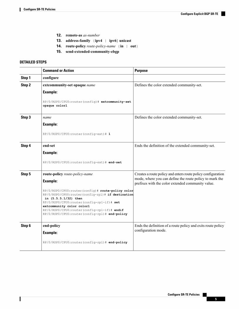
DETAILED STEPS
PurposeCommand or Action
configureStep 1
Defines the color extended community-set.extcommunity-set opaque name
Example:
Step 2
RP/0/RSP0/CPU0:router(config)# extcommunity-setopaque color1
Defines the color extended community-set.name
Example:
Step 3
RP/0/RSP0/CPU0:router(config-ext)# 1
Ends the definition of the extended community-set.end-set
Example:
Step 4
RP/0/RSP0/CPU0:router(config-ext)# end-set
Creates a route policy and enters route policy configurationmode, where you can define the route policy to mark theprefixes with the color extended community value.
route-policy route-policy-name
Example:
RP/0/RSP0/CPU0:router(config)# route-policy color
Step 5
RP/0/RSP0/CPU0:router(config-rpl)# if destinationin (5.5.5.1/32) thenRP/0/RSP0/CPU0:router(config-rpl-if)# setextcommunity color color1RP/0/RSP0/CPU0:router(config-rpl-if)# endifRP/0/RSP0/CPU0:router(config-rpl)# end-policy
Ends the definition of a route policy and exits route policyconfiguration mode.
end-policy
Example:
Step 6
RP/0/RSP0/CPU0:router(config-rpl)# end-policy
Configure SR-TE Policies5
Configure SR-TE PoliciesConfigure Explicit BGP SR-TE

PurposeCommand or Action
Specifies the BGP AS number and enters the BGPconfiguration mode, allowing you to configure the BGProuting process.
router bgp as-number
Example:
RP/0/RSP0/CPU0:router(config)# router bgp 1
Step 7
Configures the local router with a specified router ID.bgp router-id ip-address
Example:
Step 8
RP/0/RSP0/CPU0:router(config-bgp)# bgp router-id10.10.0.2
Specifies either the IPv4 or IPv6 address family and entersaddress family configuration submode.
address-family {ipv4 | ipv6} sr-policy
Example:
Step 9
RP/0/RSP0/CPU0:router(config-bgp)# address-familyipv4 sr-policy
exitStep 10
Places the router in neighbor configuration mode for BGProuting and configures the neighbor IP address as a BGPpeer.
neighbor ip-address
Example:
RP/0/RSP0/CPU0:router(config-bgp)# neighbor
Step 11
10.10.0.1
Creates a neighbor and assigns a remote autonomoussystem number to it.
remote-as as-number
Example:
Step 12
RP/0/RSP0/CPU0:router(config-bgp-nbr)# remote-as1
Specifies either the IPv4 or IPv6 address family and entersaddress family configuration submode.
address-family {ipv4 | ipv6} unicast
Example:
Step 13
RP/0/RSP0/CPU0:router(config-bgp-nbr)#address-family ipv4 unicast
Applies the specified policy to IPv4 unicast routes.route-policy route-policy-name {in | out}
Example:
Step 14
RP/0/RSP0/CPU0:router(config-bgp-nbr-af)#route-policy color out
Configure SR-TE Policies6
Configure SR-TE PoliciesConfigure Explicit BGP SR-TE

PurposeCommand or Action
Sends extended community attributes to external BorderGateway Protocol (eBGP) neighbors.
send-extended-community-ebgp
Example:
Step 15
RP/0/RSP0/CPU0:router(config-bgp-nbr-af)#send-extended-community-ebgp
Configure Interface TE MetricsUse themetric value command in SR-TE interface submode to configure the TE metric for interfaces. Thevalue range is from 0 to 2147483647.Router# configureRouter(config)# segment-routingRouter(config-sr)# traffic-engRouter(config-sr-te)# interface type interface-path-idRouter(config-sr-te-if)# metric value
Configuring TE Metric: Example
The following configuration example shows how to set the TE metric for various interfaces:segment-routingtraffic-enginterface TenGigE0/0/0/0metric 100!interface TenGigE0/0/0/1metric 1000!interface TenGigE0/0/2/0metric 50!!end
Configure Named Interface Link Admin Groups and SR-TEAffinity Maps
Use the affinity nameNAME command in SR-TE interface submode to assign affinity to interfaces. Configurethis on routers with interfaces that have an associated admin group attribute.Router# configureRouter(config)# segment-routingRouter(config-sr)# traffic-engRouter(config-sr-te)# interface type interface-path-idRouter(config-sr-if)# affinityRouter(config-sr-if-affinity)# name NAME
Use the affinity-map name NAME bit-position bit-position command in SR-TE sub-mode to define affinitymaps. The bit-position range is from 0 to 255.
Configure SR-TE Policies7
Configure SR-TE PoliciesConfigure Interface TE Metrics

Configure affinity maps on the following routers:
• Routers with interfaces that have an associated admin group attribute.
• Routers that act as SR-TE head-ends for SR policies that include affinity constraints.
Router# configureRouter(config)# segment-routingRouter(config-sr)# traffic-engRouter(config-sr-te)# affinity-mapRouter(config-sr-te-affinity-map)# name NAME bit-position bit-position
Configuring Link Admin Group: Example
The following example shows how to assign affinity to interfaces and to define affinity maps. This configurationis applicable to any router (SR-TE head-end or transit node) with colored interfaces.segment-routingtraffic-enginterface TenGigE0/0/1/1affinityname CROSSname RED!!interface TenGigE0/0/1/2affinityname RED!!interface TenGigE0/0/2/0affinityname BLUE!!affinity-mapname RED bit-position 23name BLUE bit-position 24name CROSS bit-position 25!
end
Configuring SR Policy with Dynamic Path and Affinity Constraints: Example
This example shows how to configure named affinity maps at the SR-TE head-end router with SR policiesthat include affinity constraints.segment-routingtraffic-engaffinity-mapname RED bit-position 23name BLUE bit-position 24!!!
The following example shows a configuration of an SR policy at an SR-TE head-end router. The policy hasa dynamic path with affinity constraints computed by the head-end router.segment-routingtraffic-eng
Configure SR-TE Policies8
Configure SR-TE PoliciesConfigure Named Interface Link Admin Groups and SR-TE Affinity Maps

policy foocolor 100 end-point ipv4 1.1.1.2candidate-pathspreference 100dynamicmetrictype te!!constraintsaffinityexclude-anyname RED!!!!!!
The following example shows a configuration of an SR policy at an SR-TE head-end router. The policy hasa dynamic path with affinity constraints computed by the SR-PCE.segment-routingtraffic-engpolicy baacolor 101 end-point ipv4 1.1.1.2candidate-pathspreference 100dynamicpcep!metrictype te!!constraintsaffinityexclude-anyname BLUE!!!!!!
Using Binding SegmentsThe binding segment is a local segment identifying an SR-TE policy. Each SR-TE policy is associated witha binding segment ID (BSID). The BSID is a local label that is automatically allocated for each SR-TE policywhen the SR-TE policy is instantiated.
In Cisco IOS XR 6.3.2 and later releases, you can specify an explicit BSID for an SR-TE policy. See thefollowing Explicit Binding SID section.
Note
Configure SR-TE Policies9
Configure SR-TE PoliciesUsing Binding Segments

BSID can be used to steer traffic into the SR-TE policy and across domain borders, creating seamless end-to-endinter-domain SR-TE policies. Each domain controls its local SR-TE policies; local SR-TE policies can bevalidated and rerouted if needed, independent from the remote domain’s head-end. Using binding segmentsisolates the head-end from topology changes in the remote domain.
Packets received with a BSID as top label are steered into the SR-TE policy associated with the BSID. Whenthe BSID label is popped, the SR-TE policy’s SID list is pushed.
BSID can be used in the following cases:
• Multi-Domain (inter-domain, inter-autonomous system)—BSIDs can be used to steer traffic acrossdomain borders, creating seamless end-to-end inter-domain SR-TE policies.
• Large-Scale within a single domain—The head-end can use hierarchical SR-TE policies by nesting theend-to-end (edge-to-edge) SR-TE policy within another layer of SR-TE policies(aggregation-to-aggregation). The SR-TE policies are nested within another layer of policies using theBSIDs, resulting in seamless end-to-end SR-TE policies.
• Label stack compression—If the label-stack size required for an SR-TE policy exceeds the platformcapability, the SR-TE policy can be seamlessly stitched to, or nested within, other SR-TE policies usinga binding segment.
Explicit Binding SID
Use the binding-sid explicit {fallback-dynamic | enforce-srlb} command to request that the SR-TE policyuses a BSID value that you provide. Explicit BSIDs are allocated from the segment routing local block (SRLB)or the dynamic range of labels.
A best-effort is made to request and obtain this BSID for the SR-TE policy. If requested BSID is not available(if it does not fall within the available SRLB or is already used by another application or SR-TE policy), thepolicy stays down.
You can specify how the BSID allocation behaves if the BSID value is not available:
• Fallback to dynamic allocation – If the BSID is not available, the BSID is allocated dynamically and thepolicy comes up:
Router# configureRouter(config)# segment-routingRouter(config-sr)# traffic-engRouter(config-sr-te)# binding-sid explicit fallback-dynamic
• Strict SRLB enforcement – If the BSID is not within the SRLB, the policy stays down:
Router# configureRouter(config)# segment-routingRouter(config-sr)# traffic-engRouter(config-sr-te)# binding-sid explicit enforce-srlb
Configure SR-TE Policies10
Configure SR-TE PoliciesUsing Binding Segments

Stitching SR-TE Polices Using Binding SID: ExampleIn this example, three SR-TE policies are stitched together to form a seamless end-to-end path from node 1to node 10. The path is a chain of SR-TE policies stitched together using the binding-SIDs of intermediatepolicies, providing a seamless end-to-end path.Figure 1: Stitching SR-TE Polices Using Binding SID
Table 1: Router IP Address
Prefix SID/Adj-SIDPrefix AddressRouter
Prefix SID - 16003Loopback0 - 1.1.1.33
Prefix SID - 16004
Adjacency SID - dynamic
Loopback0 - 1.1.1.4
Link node 4 to node 6 - 10.4.6.4
4
Prefix SID - 16005Loopback0 - 1.1.1.55
Prefix SID - 16006
Adjacency SID - dynamic
Loopback0 - 1.1.1.6
Link node 4 to node 6 - 10.4.6.6
6
Prefix SID - 16009Loopback0 - 1.1.1.99
Prefix SID - 16010Loopback0 - 1.1.1.1010
Step 1 On node 5, do the following:a) Define an SR-TE policy with an explicit path configured using the loopback interface IP addresses of node 9 and
node 10.b) Define an explicit binding-SID (mpls label 15888) allocated from SRLB for the SR-TE policy.
Example:
Node 5segment-routingtraffic-engsegment-list PATH-9_10index 10 address ipv4 1.1.1.9index 20 address ipv4 1.1.1.10!policy foobinding-sid mpls 15888color 777 end-point ipv4 1.1.1.10
Configure SR-TE Policies11
Configure SR-TE PoliciesStitching SR-TE Polices Using Binding SID: Example

candidate-pathspreference 100explicit segment-list PATH5-9_10!!!!!!
RP/0/RSP0/CPU0:Node-5# show segment-routing traffic-eng policy color 777
SR-TE policy database---------------------
Color: 777, End-point: 1.1.1.10Name: srte_c_777_ep_1.1.1.10Status:Admin: up Operational: up for 00:00:52 (since Aug 19 07:40:12.662)
Candidate-paths:Preference: 100 (configuration) (active)Name: fooRequested BSID: 15888PCC info:Symbolic name: cfg_foo_discr_100PLSP-ID: 70
Explicit: segment-list PATH-9_10 (valid)Weight: 1, Metric Type: TE16009 [Prefix-SID, 1.1.1.9]16010 [Prefix-SID, 1.1.1.10]
Attributes:Binding SID: 15888 (SRLB)Forward Class: 0Steering BGP disabled: noIPv6 caps enable: yes
Step 2 On node 3, do the following:a) Define an SR-TE policy with an explicit path configured using the following:
• Loopback interface IP address of node 4
• Interface IP address of link between node 4 and node 6
• Loopback interface IP address of node 5
• Binding-SID of the SR-TE policy defined in Step 1 (mpls label 15888)
This last segment allows the stitching of these policies.Note
b) Define an explicit binding-SID (mpls label 15900) allocated from SRLB for the SR-TE policy.
Example:
Node 3segment-routingtraffic-engsegment-list PATH-4_4-6_5_BSIDindex 10 address ipv4 1.1.1.4index 20 address ipv4 10.4.6.6index 30 address ipv4 1.1.1.5index 40 mpls label 15888!
Configure SR-TE Policies12
Configure SR-TE PoliciesStitching SR-TE Polices Using Binding SID: Example

policy baabinding-sid mpls 15900color 777 end-point ipv4 1.1.1.5candidate-pathspreference 100explicit segment-list PATH-4_4-6_5_BSID!!!!!!
RP/0/RSP0/CPU0:Node-3# show segment-routing traffic-eng policy color 777
SR-TE policy database---------------------
Color: 777, End-point: 1.1.1.5Name: srte_c_777_ep_1.1.1.5Status:Admin: up Operational: up for 00:00:32 (since Aug 19 07:40:32.662)
Candidate-paths:Preference: 100 (configuration) (active)Name: baaRequested BSID: 15900PCC info:Symbolic name: cfg_baa_discr_100PLSP-ID: 70
Explicit: segment-list PATH-4_4-6_5_BSID (valid)Weight: 1, Metric Type: TE16004 [Prefix-SID, 1.1.1.4]80005 [Adjacency-SID, 10.4.6.4 - 10.4.6.6]16005 [Prefix-SID, 1.1.1.5]15888
Attributes:Binding SID: 15900 (SRLB)Forward Class: 0Steering BGP disabled: noIPv6 caps enable: yes
Step 3 On node 1, define an SR-TE policy with an explicit path configured using the loopback interface IP address of node 3and the binding-SID of the SR-TE policy defined in step 2 (mpls label 15900). This last segment allows the stitching ofthese policies.
Example:
Node 1segment-routingtraffic-engsegment-list PATH-3_BSIDindex 10 address ipv4 1.1.1.3index 20 mpls label 15900!policy barcolor 777 end-point ipv4 1.1.1.3candidate-pathspreference 100explicit segment-list PATH-3_BSID!!!
Configure SR-TE Policies13
Configure SR-TE PoliciesStitching SR-TE Polices Using Binding SID: Example

!!!
RP/0/RSP0/CPU0:Node-1# show segment-routing traffic-eng policy color 777
SR-TE policy database---------------------
Color: 777, End-point: 1.1.1.3Name: srte_c_777_ep_1.1.1.3Status:Admin: up Operational: up for 00:00:12 (since Aug 19 07:40:52.662)
Candidate-paths:Preference: 100 (configuration) (active)Name: barRequested BSID: dynamicPCC info:Symbolic name: cfg_bar_discr_100PLSP-ID: 70
Explicit: segment-list PATH-3_BSID (valid)Weight: 1, Metric Type: TE16003 [Prefix-SID, 1.1.1.3]15900
Attributes:Binding SID: 80021Forward Class: 0Steering BGP disabled: noIPv6 caps enable: yes
Configure SR-TE Policies14
Configure SR-TE PoliciesStitching SR-TE Polices Using Binding SID: Example