
ConfigGuide_ATMQoS.pdf
44
Power Ethernet WLAN Plug-in ISDN Internet DSL ATM Quality of Service Configuration Guide R7.4 and higher Thomson Gateway Residential DSL Gateways and Business DSL Routers
-
Upload
arisgotheforce -
Category
Documents
-
view
23 -
download
0
description
Config Guide
Transcript of ConfigGuide_ATMQoS.pdf
Po
wer
Eth
ern
et
WLA
N
Plu
g-i
n
ISD
N
Inte
rnet
DS
L
ATM Quality of ServiceConfiguration Guide
R7.4 and higher
Thomson GatewayResidential DSL Gateways and Business DSL Routers

Thomson GatewayATM Quality of Service Configuration Guide

Copyright
Copyright ©1999-2008 THOMSON. All rights reserved.
Distribution and copying of this document, use and communication of its contents is not permitted without written authorization from THOMSON. The content of this document is furnished for informational use only, may be subject to change without notice, and should not be construed as a commitment by THOMSON. THOMSON assumes no responsibility or liability for any errors or inaccuracies that may appear in this document.
Thomson Telecom BelgiumPrins Boudewijnlaan, 47 B-2650 Edegem Belgium
http://www.thomson-broadband.com
Trademarks
The following trademarks may be used in this document:
DECT is a trademark of ETSI.
Bluetooth® word mark and logos are owned by the Bluetooth SIG, Inc.
Ethernet™ is a trademark of Xerox Corporation.
Wi-Fi®, WMM® and the Wi-Fi logo are registered trademarks of the Wi-Fi Alliance®. "Wi-Fi CERTIFIED", "Wi-Fi ZONE", "Wi-Fi Protected Access", "Wi-Fi Multimedia", "Wi-Fi Protected Setup", WPA", WPA2" and their respective logos of the Wi-Fi Alliance®.
UPnP™ is a certification mark of the UPnP™ Implementers Corporation.
Microsoft®, MS-DOS®, Windows®, Windows NT® and Windows Vista® are either registered trademarks or trademarks of Microsoft Corporation in the United States and/or other countries.
Apple® and Mac OS® are registered trademarks of Apple Computer, Incorporated, registered in the United States and other countries.
UNIX® is a registered trademark of UNIX System Laboratories, Incorporated.
Adobe®, the Adobe logo, Acrobat and Acrobat Reader are trademarks or registered trademarks of Adobe Systems, Incor-porated, registered in the United States and/or other countries.
Other brands and product names may be trademarks or registered trademarks of their respective holders.
Document Information
Status: v1.0 (April 2008)Reference: E-DOC-CTC-20080307-0002Short Title: ATM Quality of Service Configuration Guide R7.4 and higher

Contents
About this ATM Quality of Service Configuration Guide ....... 1
1 General Overview........................................................................ 3
1.1 Basic Concepts................................................................................................ 4
1.2 ATM Quality of Service ................................................................................... 6
2 The Thomson Gateway and Quality of Service ........................ 9
2.1 ATM Quality of Service ................................................................................. 10
2.2 Configuring ATM Quality of Service ............................................................. 12
2.2.1 Creating ATM QoSbook Profiles ......................................................................................................... 13
2.2.2 Using ATM QoSbook Profiles.............................................................................................................. 15
2.2.3 ILMI ........................................................................................................................................................ 16
2.3 Classification and Forwarding ...................................................................... 18
2.4 Summary / Overview ..................................................................................... 19
3 Configuring QoS on the Thomson Gateway........................... 21
3.1 Example: High Priority Data via PPTP........................................................... 22
3.2 Example: Real-time Multimedia Data and Label Based Routing with ToS-byte Marking ......................................................................................................... 25
3.3 Example: ILMI and Dynamic QoS Configuration with PPPoE Relay.............. 29
3.4 Example: SOHO with Two Sites .................................................................... 32
E-DOC-CTC-20080307-0002 v1.0 i

ii
Contents
E-DOC-CTC-20080307-0002 v1.0

About this ATM Quality of Service Configuration Guide
About this ATM Quality of Service Configuration Guide
Used Symbols
ApplicabilityThis Configuration Guide applies to all Thomson Gateway Software Release R5.4 and higher and higher.
Typographical ConventionsFollowing typographical convention is used throughout this manual:
Sample text indicates a hyperlink to a Web site.
Example: For more information, visit us at www.thomson-broadband.com.
Sample text indicates an internal cross-reference.
Example: If you want to know more about guide, see “1 Introduction” on page 7”.
Sample text indicates an important content-related word.
Example: To enter the network, you must authenticate yourself.
Sample text indicates a GUI element (commands on menus and buttons, dialog box elements, file names, paths and folders).
Example: On the File menu, click Open to open a file.
Documentation and software updatesTHOMSON continuously develops new solutions, but is also committed to improving its existing products.
For more information on THOMSON's latest technological innovations, documents and software releases, visit us at http://www.thomson-broadband.com.
A note provides additional information about a topic.
A caution warns you about potential problems or specific precautions that need to be taken.
E-DOC-CTC-20080307-0002 v1.0 1

2
About this ATM Quality of Service Configuration Guide
E-DOC-CTC-20080307-0002 v1.0

General Overview
1 General Overview
IntroductionThis chapter provides a technical overview of Quality of Service in general. Some basic concepts are briefly touched, followed by a more detailed introduction to ATM Quality of Service principles and mechanisms.
E-DOC-CTC-20080307-0002 v1.0 3

4
General Overview
1.1 Basic Concepts
What is Quality of ServiceThere is no common or formal definition of Quality of Service (QoS). One possible definition is that QoS is the ability of a network element (application, router, host) to have some level of assurance that its data traffic and service requirements can be satisfied.
Nowadays the total amount of data traffic increases, while new types of data emerge like voice data, video data, audio data. These new types of data pose new requirements for data transport for example low latency, low data loss… To meet these requirements, the entire network must ensure these data transport requirements via a connection service guarantee. Such a connection service guarantee can both be applied to connection-oriented networks on a connection base and to packet-oriented networks on a data stream or data type base.
Quality of Service allows specifying a connection service guarantee via a set of connection parameters. Throughout the network, this set of connection parameters will be used to handle the connection data in a way to achieve the connection service guarantee. This handling includes reserving bandwidth, priority based queuing, scheduling, modifying data characteristics,…
Examples of connection parameters include the maximum amount of bandwidth that may be used, the guaranteed amount of bandwidth that will always be available, the maximum delay the data can experience throughout the network, a priority indication,…
Relative / Guaranteed QoSThere are two different approaches to achieve QoS. The first is “relative QoS” (also referred to as Differentiated QoS) where a priority indication is given as connection parameter to certain data or to a connection. This data or connection will be handled with precedence over data or connections with less priority. Obviously, this guarantees no specified bandwidth or latency, but it is the easiest approach for achieving some level of QoS for high priority data. Examples of “relative QoS” are Differentiated Services (DiffServ) and Ethernet VLAN user priority indication.
In case of relative QoS, data is often specified to belong to a certain Class of Service (CoS) instead of QoS. Treatment and priority of data throughout the network is configured for each supported CoS.
The second approach is “guaranteed QoS” where measurable connection parameters are specified for certain data or for a connection, for example a guaranteed amount of bandwidth or delay across the network. This allows for an exact specification and measurement of the Quality of Service of data or a connection. Note that this approach is slightly more complicated than “relative QoS” because the connection parameters have to be specified and may be verified throughout the entire network. Examples of “guaranteed QoS” are Integrated Services (IntServ) and ATM QoS.
E-DOC-CTC-20080307-0002 v1.0

General Overview
Connection Admission ControlWhen a network node guarantees a certain Quality of Service to a data stream or connection, new streams or connections that are set up afterwards might impact the QoS of the first stream or connection. To prevent this, the node can do Connection Admission Control (CAC) to reserve resources for each admitted stream. Reserved resources can be bandwidth, queue space, memory, CPU cycles, …
Usually, a connection or data stream request is made to the network node. The node will take the requested connection parameters into account and will verify whether the requested QoS can be guaranteed. If it can be guaranteed, the data stream or connection request is granted and necessary resources are reserved.
Connection Admission Control is used in guaranteed QoS mechanisms. As there are no measurable QoS guarantees in case of relative QoS, there is no need to reserve resources on a data stream or connection base. Relative QoS will usually distribute resources amongst the classes of service.
ShapingTo prevent data being discarded in the network by policing, it is in the originator of the data’s interest to make sure that the data sent is conform the connection parameters (again in case of guaranteed QoS). This may involve changing data characteristics and is called shaping.
Control PlaneService Level agreements or QoS connection parameters may be signalled via a control protocol. Examples for ATM are Switched Virtual Circuits (SVCs) and Integrated Local Management Interface (ILMI). Example on IP level is the Resource Reservation Protocol (RSVP).
A control plane is very important for each QoS mechanism application. It addresses both the configuration of the Service Level Agreement across the network and prevents end users from using QoS guarantees or CoS classes that are not part of the SLA.
QoS control planes are most commonly used for guaranteed QoS, but can also be applied to relative QoS.
E-DOC-CTC-20080307-0002 v1.0 5

6
General Overview
1.2 ATM Quality of Service
QoS CategoriesThis section presents a brief introduction to ATM Quality of Service, with focus on the QoS service categories that are most applicable to the Thomson Gateway and its functionality. Other ATM service categories may be implemented in future Thomson Gateway products.
ATM is commonly used in the DSL access network because it is perfectly suited for the QoS requirements mentioned in “1.1 Basic Concepts” on page 4.
ATM has following benefits:
Integration of multiple traffic types
Efficient bandwidth use
Guaranteed bandwidth and resource allocation
High service availability
Multiple QoS categories support
Suitable for data that is both sensitive and insensitive to delay and/or data loss
Connection Services ParametersATM QoS is ‘guaranteed QoS’. Connection service guarantees are specified per ATM VP/VC by a set of measurable connection parameters.
Following connection parameters may characterize an ATM connection:
Peak Cell Rate (PCR): maximum number of ATM cells per second that may be sent on the connection.
Sustainable Cell Rate (SCR): average number of ATM cells per second that may be sent on the connection.
Maximum Burst Size (MBS): Maximum number of ATM cells per second that may be sent in a burst, and thus exceeding the average number of cells (SCR) up to the maximum number of cells (PCR) for a limited number of ATM cells defined by MBS.
Cell Delay Variation Tolerance (CDVT): defines the tolerated variation in ATM cell delay (e.g. due to the occurrence of cell multiplexing). May be explicitly or implicitly defined by the network.
Cell Loss Ratio (CLR): Number of lost cells with regard to the total number of transmitted cells. This is an objective for the entire network.
Maximum Cell Transfer Delay (maxCTD): defines the maximum delay an ATM cell may experience during transfer throughout the ATM network. Cells that are delayed beyond the maxCTD value are considered of less importance. This parameter is mainly used to characterize real-time connections.
E-DOC-CTC-20080307-0002 v1.0

General Overview
QoS Services with Guaranteed BandwidthBased upon the aforementioned connection parameters, following QoS service categories are defined:
Constant Bit Rate (CBR): real-time connection with a specified amount of guaranteed bandwidth (PCR) that is continuously available during the connection life-time. The maximum cell delay is characterized by maxCTD as illustrated below. CBR is typically used for interactive video and/or audio distribution and/or retrieval.
Real-Time Variable Bit Rate (VBR-rt): similar as CBR intended for real-time applications with constrained delay and delay variation values, but which can benefit from variable bit-rates. The average guaranteed bandwidth is SCR, but data up to PCR may be sent for a limited amount of data specified by MBS. A VBR-rt connection is characterized by PCR, SCR, MBS, and maxCTD parameters, as illustrated below. Typically used for real-time traffic with a burst-characteristic.
Non-Real-Time Variable Bit Rate (VBR-nrt): intended for non-real-time applications that have bursty traffic characteristics and no strict transfer delay requirements but which require an amount of guaranteed bandwidth. A VBR-nrt connection is characterized by an average guaranteed bandwidth (SCR) up to a maximum guaranteed bandwidth (PCR) for a burst with specified maximum size (MBS) as illustrated in the figure below. VBR-nrt is typically used for bursty data transfer, banking transactions, ERP,…
bps
Time
PCRNON-CONFORMING
GUARANTEED
maxCTD
bps
Time
PCR
NON-CONFORMING
GUARANTEED
SCR
MBSmaxCTD
bps
Time
PCR
NON-CONFORMING
GUARANTEED
SCR
MBS
E-DOC-CTC-20080307-0002 v1.0 7

8
General Overview
QoS Services with Non Guaranteed BandwidthUnspecified Bit Rate (UBR): intended for non-real-time applications that require no guaranteed bandwidth. A UBR connection is characterized by a maximum available bandwidth (PCR), as illustrated in the figure below. All UBR traffic is non-guaranteed, and may be tagged/discarded or experience variable delay throughout the network. UBR is the most common used service class/category and used for text/data/image transfer and non-critical applications.
It is important to be aware of the notion of guaranteed bandwidth and non-guaranteed bandwidth. The figures that illustrate the service categories clearly show which part of the bandwidth is guaranteed and which part isn’t. Important is that the entire ATM network commits to delivery of data traffic up till the ‘guaranteed’ bandwidth. Non-guaranteed bandwidth is ‘best-effort’, and is unpredictable in availability and transfer delay.
Connection Admission ControlThe guaranteed bandwidth is used for Connection Admission Control (CAC). Connection Admission Control verifies if a connection establishment request can be accepted with the resources that are at that moment available.
Resources such as the available bandwidth and the queue-filling levels are typically most relevant for admission control. Indeed, at the moment there is insufficient bandwidth left or packets can no longer be queued, data will be lost. The main purpose of CAC is to prevent data-loss and to assure the quality of service.
Connection Admission Control is done on every ATM connection setup for example statically configured or dynamically configured via ILMI. The connection parameters are used together with the currently available bandwidth and queue filling levels to calculate whether the ATM connection is admitted or not.
ShapingObviously, the source of the ATM data benefits from sending data that is conform the service category. Data that is non-conforming may be discarded, which will probably result in retransmission of data and an overall reduced quality of service. Most sources of ATM data (and other network elements) will use shaping to adjust the data traffic characteristics to the specified connection parameters. Shaping is achieved by queuing data and limiting the upstream data rate to the PCR (for UBR and CBR) or SCR up to PCR (for VBR-rt and VBR-nrt), and limiting the burst length to MBS (for VBR-rt and VBR-nrt) if necessary.
bps
Time
PCRNON-CONFORMING
NON-GUARANTEED
E-DOC-CTC-20080307-0002 v1.0

The Thomson Gateway and Quality of Service
2 The Thomson Gateway and Quality of Service
OverviewThe Thomson Gateway supports ATM Quality of Service in combination with an extensive way of forwarding data via a certain ATM connection with corresponding QoS configuration.
E-DOC-CTC-20080307-0002 v1.0 9
10
The Thomson Gateway and Quality of Service
2.1 ATM Quality of Service
ATM cell shapingATM connections terminated by the router or terminated bridge connections are per VC queued. This means packets forwarded over one ATM VC all end up in the same VC queue. Packets are segmented into ATM cells and shaped to the configured connection parameters of the particular VC.
Shaped ATM cells are forwarded to the ATM switch that will switch the ATM cells to the destination ATM interface. After being switched, the ATM cells for a particular VC are queued in one of the interfaces’ ATM category queues.
The ATM QoS category queues of an ATM interface are fixed priority scheduled.
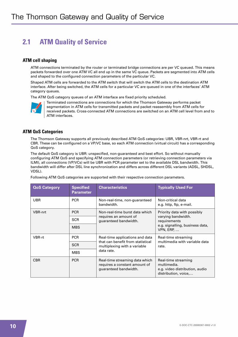
ATM QoS CategoriesThe Thomson Gateway supports all previously described ATM QoS categories: UBR, VBR-nrt, VBR-rt and CBR. These can be configured on a VP/VC base, so each ATM connection (virtual circuit) has a corresponding QoS category.
The default QoS category is UBR: unspecified, non-guaranteed and best effort. So without manually configuring ATM QoS and specifying ATM connection parameters (or retrieving connection parameters via ILMI), all connections (VP/VCs) will be UBR with PCR parameter set to the available DSL bandwidth. This bandwidth will differ after DSL line synchronization and differs across different DSL variants (ADSL, SHDSL, VDSL).
Following ATM QoS categories are supported with their respective connection parameters.
Terminated connections are connections for which the Thomson Gateway performs packet segmentation in ATM cells for transmitted packets and packet reassembly from ATM cells for received packets. Cross-connected ATM connections are switched on an ATM cell level from and to ATM interfaces.
QoS Category Specified
Parameter
Characteristics Typically Used For
UBR PCR Non-real-time, non-guaranteed bandwidth.
Non-critical datae.g. http, ftp, e-mail.
VBR-nrt PCR Non-real-time burst data which requires an amount of guaranteed bandwidth.
Priority data with possibly varying bandwidth. requirementse.g. signalling, business data, VPN, ERP, …
SCR
MBS
VBR-rt PCR Real-time applications and data that can benefit from statistical multiplexing with a variable data rate.
Real-time streaming multimedia with variable data rate.SCR
MBS
CBR PCR Real-time streaming data which requires a constant amount of guaranteed bandwidth.
Real-time streaming multimedia.e.g. video distribution, audio distribution, voice,…
E-DOC-CTC-20080307-0002 v1.0

The Thomson Gateway and Quality of Service
Connection Admission ControlConnection Admission Control (CAC) is performed for all ATM connection requests if the feature is enabled.
For non-guaranteed bandwidth requests (UBR QoS category), the connections are always admitted, regardless of the available bandwidth and queue space at that moment. UBR connections can compete for any available bandwidth, but guaranteed bandwidth (resources reserved for other connections) will be available to guaranteed bandwidth connections.
For guaranteed bandwidth connection requests (VBR-nrt, VBR-rt or CBR QoS categories), connection admission control is more complex because resources have to be reserved to guarantee the QoS category connection parameters.
In case of a CBR QoS category connection request, the PCR is the amount of guaranteed bandwidth requested. If the sum of all currently reserved bandwidth with the PCR is less than or equal to the total available (DSL) bandwidth, the connection is admitted and the bandwidth will be reserved for this connection.
Variable bit rate QoS categories need both bandwidth and queue size to be reserved because of both the guaranteed bandwidth and burst size connection parameters. The Thomson Gateway uses statistical multiplexing for admitting variable bit rate connection requests.
The total available bandwidth can change after DSL line synchronization. If the DSL line rate changes, all CAC and resource reservations will be recalculated. Connections that are no longer admitted will not be removed but will internally be marked as overbooked connections. Overbooked connection ATM cells will be discarded prior to properly admitted connection cells in case of congestion.
ShapingAll terminated ATM connections are shaped to the ATM QoS category connection parameters. Even in case of UBR connections with the PCR parameter set to line rate, after segmentation into ATM cells each connection is shaped to the line rate of that moment.
Shaping is done in hardware according to the connection parameters:
PCR shaping in case of UBR and CBR.
PCR, SCR and MBS shaping in case of VBR-nrt and VBR-rt.
Shaped user ATM cells are sent to the ATM switch with the ATM CLP flag set to 0 (indicating normal priority).
Overbooking can be allowed by configuring the overbooking parameter in the ATM CAC menu. Overbooking will be expressed in percentage of the available bandwidth. By default overbooking will be disabled, meaning the total amount of reservations can not exceed the total bandwidth available.
E-DOC-CTC-20080307-0002 v1.0 11

12
The Thomson Gateway and Quality of Service
2.2 Configuring ATM Quality of Service
ATM QoSbook ProfilesThis section briefly explains how to create and use ATM QoSbook profiles. QoSbook profiles are a configured set of ATM QoS connection parameters that can be applied to an ATM VC/VC connection.
First, the creation of new profiles will be discussed followed by an overview of how to apply and use these profiles for ATM VP/VC connections.
ATM QoS configurationATM QoS is configured in 4 steps:
1 The definition of the RX connection traffic descriptor (ctd). This contains the ATM QoS parameters for the down stream traffic. (See “ATM QoS parameters” on page 16)
2 The definition of the TX connection traffic descriptor (ctd). This contains the ATM QoS parameters for the down stream traffic. (See “ATM QoS parameters” on page 16)
3 The creation of a QoSbook entry consisting of an RX-ctd and a TX-ctd.
4 Assigning a QoSbook entry to an ATM VP/VC.
E-DOC-CTC-20080307-0002 v1.0

The Thomson Gateway and Quality of Service
2.2.1 Creating ATM QoSbook Profiles
IntroductionAll ATM QoS categories and their connection parameters are organized and configurable in the Thomson Gateway QoSbook. This QoSbook allows creation of profiles that at a later stage can be linked to VP/VC connections.
The QoSbook is configurable via the Command Line Interface (CLI).
ATM QoS parametersEach profile is stored in the QoSbook as a QoSbook entry. A QoSbook entry is defined by a TX and RX connection traffic descriptor (ctd). A single ctd entry has following parameters specified:
ATM QoSbook parametersQoSbook entries can be displayed and configured in two units, kilobits (kilobit equals one thousand bits) per second (kb/s) or ATM cells per second (cps).
Execute the following command to set the QoSbook format to cells:
Assuming the unit is configured as cells per second, the following steps are needed to create a new QoSbook profile for a VBR-rt ATM QoS category.
1 Create a ctd entry for the upstream:
Parameter Value or Unit Comment
Name Entry name Any given name.
Conformance ubr / vbr / cbr ATM Service Category.
Peakrate In kb/s or cps PCR in ATM cells per second or kbits/s.0 (line-rate) is only allowed as PCR for UBR connections.
Sustrate In kb/s or cps SCR in ATM cells per second or kbits/s.”n/a” for type ubr/cbr.Must be specified different from 0 in case of vbr-rt / vbr-nrt.
Maxburst In bytes or cells MBS in ATM cells per second or kbytes/s.
realtime Enabled / Disabled Conformance definition.
:atm qosbook config format=cells
The ATM QoSbook config format parameter applies to all ATM QoSbook entries. Only one format can be chosen. If the QoSbook config format parameter is changed, the QoSbook parameters already configured will automatically be converted by the Thomson Gateway.
=>:atm qosbook ctdadd name = vbr1-rt-txconformance = VBR [peakrate] = 128[sustrate] = 64[maxburst] = 32[realtime] = enabled
E-DOC-CTC-20080307-0002 v1.0 13

14
The Thomson Gateway and Quality of Service
2 Create a ctd entry for the downstream:
3 Create a QoSbook entry using the ctd entries we have just created:
=>:atm qosbook ctdadd name = vbr1-rt-rxconformance = VBR [peakrate] = 128[sustrate] = 64[maxburst] = 64[realtime] = enabled
=>:atm qosbook addname = vbr1-rt[txctd] = vbr1-rt-tx[rxctd] = vbr1-rt-rx
If the maximum burst size unit is bytes, this burst size (without AAL5 and ATM encapsulation) is recalculated into the corresponding MBS in ATM cells. Note that this may result in a different burstsize being displayed because of the recalculation into a multiple of ATM cell payload (48 bytes).
Entering 0 as PCR is interpreted as PCR shaping to the available DSL bandwidth (called line rate). If the DSL line is at this stage not yet initialized, 800kb/s is chosen as default for ADSL but adjusted to the actual value as soon as the line initialization takes place. Note that linerate shaping is only useful for UBR, and should not be applied for VBR-nrt, VBR-rt or CBR.
E-DOC-CTC-20080307-0002 v1.0

The Thomson Gateway and Quality of Service
2.2.2 Using ATM QoSbook Profiles
ATM QoSbook ProfilesOnce profiles are created as QoSbook entries, a profile may be linked to an ATM connection during connection establishment.
For terminated ATM connections, a connection can refer to a QoSbook entry via the interface configuration. This profile will be applied to the ATM connection that corresponds to the interface destination phonebook entry. The Command Line Interface (CLI) provides an ifconfig command that allows configuration of the QoSbook profile for an ATM VP/VC connection.
Proceed as follows to assign the QoSbook profile we created to a VP/VC:
=>:atm ifadd intf=atm_0_35=>:atm ifadd intf=atm_1=>:atm ifconfigintf = atm_0_35[dest] = atm_pvc_0_35=>:atm ifconfig intf = atm_1 [dest] = phone_1[qos] = vbr1-rt[encaps] = llc[retry] = 10[fcs] = disabled[ulp] = mac
E-DOC-CTC-20080307-0002 v1.0 15

16
The Thomson Gateway and Quality of Service
2.2.3 ILMI
The Integrated Local Management InterfaceIntegrated Local Management Interface (ILMI) is a feature that enables dynamic configuration of ATM connection parameters. This section will briefly touch the ILMI principles and configuration on the Thomson Gateway.
ILMI PrinciplesILMI uses a dedicated ATM VPI/VCI 0/16 channel to configure the ATM Connection parameters on the Thomson Gateway. The protocol used is SNMP encapsulated in AAL5.
Via SNMP “trap” commands, the remote site (for example a DSLAM) can notify the Thomson Gateway of changed ATM connection parameters. The Thomson Gateway will issue SNMP “get” commands to retrieve all parameters and update the ATM Interface Management Information Base (MIB). This ATM Interface MIB contains ATM VP/VC configuration including the ATM QoS category and QoS connection parameters.
MIBs supported by the Thomson Gateway are:
ATM Forum ILMI Specification (af-ilmi-0065.000)
ATM Forum Autoconfiguration of PVCs Specification (af-nm-0122.000)
ATM Forum Addendum to the ILMI Autoconfiguration Extension (fb-nm-0165.000)
Upon ATM Connection parameter configuration via ILMI, the Thomson Gateway will automatically create phonebook entries and/or ATM QoSbook profiles.Connections already using these phonebook entries (PPPoA, PPPoE, IPoA, Routed Ethernet) will be updated with references to the applicable new ILMI QoSbook entries if configured as ILMI PVC type. In case no connections are using the dynamic phonebook entries, bridge or PPPoE connection will be created and bound to these phonebook entries.
Overall, connection parameters configured via ILMI will result in proper shaping, QoS category queuing and scheduling.
Configuring ILMITwo ILMI modes are configurable via the CLI
Active: enable both ILMI (VP/VC 0/16) and pseudo-ILMI (VP/VC 15/16). When connection parameters are written to the MIB, use these parameters to configure phonebook entries, QoSbook profiles and bind bridge or PPPoE interfaces on top.
Passive: enable both ILMI (VP/VC 0/16) and pseudo-ILMI (VP/VC 15/16). When connection parameters are written to the MIB, display this information on CLI or web interface but do not use these parameters for configuration.
Execute the following command to configure the ILMI mode as active:
For a PVC connection that is automatically configured via ILMI, the type of interface that will be bound (if no other interfaces are already bound) to this PVC can be configured. Execute the following command to select the type of interface to be bound to the ILMI PVC:
The Thomson Gateway is compliant with the standards defined by DSL-Forum in TR-37 and TR-62.
:autopvc config mode=active
:autopvc config type=pppoe
E-DOC-CTC-20080307-0002 v1.0

The Thomson Gateway and Quality of Service
Thomson Gateway gateways and routers also support overruling the ILMI UBR PVC PCR connection parameter with a configurable PCR value. This allows for example configuring the UBR PCR to the line rate of the DSL connection. Indeed, for UBR connections without explicit PCR configuration (because the network might do policing or UBR connections), the PCR can be configured to use any available DSL bandwidth.
To configure the overwriting of the ILMI PVC PCR in case of UBR connections, proceed as follows:
1 Configure the PCR with 0 meaning DSL line-rate:
2 Enable the UBR PVC overwriting:
See “3 Configuring QoS on the Thomson Gateway” on page 21 for examples.
=>:autopvc config peakrate=0
=>:autopvc config overwrite=enabled
E-DOC-CTC-20080307-0002 v1.0 17
18
The Thomson Gateway and Quality of Service
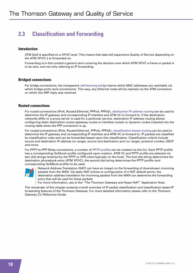
2.3 Classification and Forwarding
IntroductionATM QoS is specified on a VP/VC level. This means that data will experience Quality of Service depending on the ATM VP/VC it is forwarded on.
Forwarding is in this context a generic term covering the decision over which ATM VP/VC a frame or packet is to be sent, and not only referring to IP forwarding.
Bridged connectionsFor bridge connections, the transparent self-learning bridge learns which MAC addresses are reachable via which bridge ports (and connections). This way, any Ethernet node will be reached via the ATM connection on which the ARP reply was received.
Routed connectionsFor routed connections (IPoA, Routed Ethernet, PPPoA, PPPoE), destination IP address routing can be used to determine the IP gateway and corresponding IP interface and ATM VC to forward to. If the destination networks differ or a proxy server is used for a particular service, destination IP address routing allows configuring static destination routes (gateway routes or interface routes) or dynamic routes (injected into the routing table when the PPP connection is up.
For routed connections (IPoA, Routed Ethernet, PPPoA, PPPoE), classification-based routing can be used to determine the IP gateway and corresponding IP interface and ATM VC to forward to. IP packets are classified by classification rules and can be forwarded based upon this classification. Classification criteria include source and destination IP address (or range), source and destination port (or range), protocol number, DSCP and more.
For PPTP-to-PPP Relay connections, a number of PPTP profiles can be created via the CLI. Each PPTP profile has a corresponding QoSbook profile configured upon creation. ATM VC and PPTP profile are selected via two dial strings (entered by the PPTP or VPN client typically on the host). The first dial string determines the destination phonebook entry (ATM VP/VC), the second dial string determines the PPTP profile (and corresponding QoSBook profile) to be used.
The remainder of this chapter presents a brief overview of IP packet classification and classification based IP forwarding features of the Thomson Gateway. For more detailed information please refer to the Thomson Gateway CLI Reference Guide.
Network Address Translation (NAT) can have an impact on the forwarding of downstream incoming packets from the WAN. Via static NAT entries or configuration of a NAT default server, the destination address translation for incoming packets from the WAN can determine the forwarding entry that will be used for these packets. For more information, see to the “The Thomson Gateway and Hyper-NAT” Application Note.
E-DOC-CTC-20080307-0002 v1.0

The Thomson Gateway and Quality of Service
2.4 Summary / Overview
QoS featuresAs a summary, this chapter provides a brief overview of the Thomson Gateway QoS features.
Up to 8 VP/VCs with 8 transmit queues for SAR.
Supported ATM QoS categories:
UBR
VBR-nrt
VBR-rt
CBR
Upstream PCR (UBR, CBR) and PCR/SCR/MBS (VBR-nrt and VBR-rt) shaping per VC.
Connection Admission Control (CAC) using statistical multiplexing to guarantee bandwidth. Overbooking can optionally be enabled.
Per VC queuing on frame level (for SAR) for terminated ATM connections.
ILMI 4.0 auto-configuration of ATM connection parameters (with binding to existing or new interfaces). ILMI will consume one of the eight VP/VCs that can be used.
E-DOC-CTC-20080307-0002 v1.0 19

20
The Thomson Gateway and Quality of Service
E-DOC-CTC-20080307-0002 v1.0
Configuring QoS on the Thomson Gateway
3 Configuring QoS on the Thomson Gateway
IntroductionThis chapter presents a number of practical examples on how to use and configure Quality of Service on the Thomson Gateway.
Configuration will typically be done via the Command Line Interface (CLI). Please refer to the Thomson Gateway CLI Reference Guide.
E-DOC-CTC-20080307-0002 v1.0 21
22
Configuring QoS on the Thomson Gateway
3.1 Example: High Priority Data via PPTP
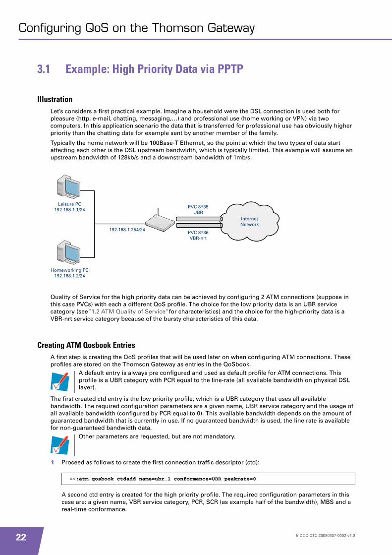
IllustrationLet’s considers a first practical example. Imagine a household were the DSL connection is used both for pleasure (http, e-mail, chatting, messaging,…) and professional use (home working or VPN) via two computers. In this application scenario the data that is transferred for professional use has obviously higher priority than the chatting data for example sent by another member of the family.
Typically the home network will be 100Base-T Ethernet, so the point at which the two types of data start affecting each other is the DSL upstream bandwidth, which is typically limited. This example will assume an upstream bandwidth of 128kb/s and a downstream bandwidth of 1mb/s.
Quality of Service for the high priority data can be achieved by configuring 2 ATM connections (suppose in this case PVCs) with each a different QoS profile. The choice for the low priority data is an UBR service category (see“1.2 ATM Quality of Service”for characteristics) and the choice for the high-priority data is a VBR-nrt service category because of the bursty characteristics of this data.
Creating ATM Qosbook EntriesA first step is creating the QoS profiles that will be used later on when configuring ATM connections. These profiles are stored on the Thomson Gateway as entries in the QoSbook.
The first created ctd entry is the low priority profile, which is a UBR category that uses all available bandwidth. The required configuration parameters are a given name, UBR service category and the usage of all available bandwidth (configured by PCR equal to 0). This available bandwidth depends on the amount of guaranteed bandwidth that is currently in use. If no guaranteed bandwidth is used, the line rate is available for non-guaranteed bandwidth data.
1 Proceed as follows to create the first connection traffic descriptor (ctd):
A second ctd entry is created for the high priority profile. The required configuration parameters in this case are: a given name, VBR service category, PCR, SCR (as example half of the bandwidth), MBS and a real-time conformance.
192.168.1.254/24
Leisure PC 192.168.1.1/24
Homeworking PC192.168.1.2/24
PVC 8*35 UBR
PVC 8*36 VBR-nrt
Internet Network
A default entry is always pre configured and used as default profile for ATM connections. This profile is a UBR category with PCR equal to the line-rate (all available bandwidth on physical DSL layer).
Other parameters are requested, but are not mandatory.
=>:atm qosbook ctdadd name=ubr_1 conformance=UBR peakrate=0
E-DOC-CTC-20080307-0002 v1.0
Configuring QoS on the Thomson Gateway
2 Proceed as follows to create the second ctd:
3 Proceed as follows to assign the created ctd entries to the QoSbook profiles:
The QoSbook ctdlist command gives an overview of all configured Connection Traffic Descriptors.
The QoSbook list command gives an overview of all configured QoSbook entries.
The Ref column in the QoSbook overview indicates the number of protocol interfaces that are actually configured with this QoS profile. For example, typically there are a number of default connections configured that use the default QoS profile.
Creating Phonebook EntriesNow that the profiles are created (as QoSbook entries), configure an ATM connection and link the appropriate profile to it.
As an example, a PPP dialup connection will be used on each of the two PCs. Transported towards the Thomson Gateway via PPTP, the connections are relayed to PPPoA over the appropriate ATM connection.
Execute the following commands to add the ATM connections in the Thomson Gateway Phonebook:
Creating PPTP ProfilesNow to link the appropriate QoS profiles to these connections, protocol interfaces need to be specified, in this case PPTP profiles (but may also be PPP, IPoA or bridging interfaces in other configurations). For this particular case, the PPTP name is chosen different from the phonebook connection name with the intention to keep the example as clear as possible.
Execute the following commands to create the profiles:
Execute the following command to enable the PPTP service:
=>:atm qosbook ctdadd name=vbr_64 conformance=VBR peakrate=128sustrate=64 maxburst=32 realtime=disabled
=>:atm qosbook add name=ubr txctd=ubr_1 rxctd=ubr_1=>:atm qosbook add name=vbr_64 txctd=vbr_64 rxctd=vbr_64
=>:atm qosbook ctdlistName Ref Conf Peak Sust Burst Minrate Frame Cdvt RT FD
(cps) (cps) (cells) (cps) (cells)ubr_1 2 UBR linerate 0 0 0 0 0 disabled disabledvbr_64 0 VBR 128 64 32 0 0 0 disabled disabled
=>:atm qosbook listName Ref Tx CTD Rx CTDubr 1 ubr_1 ubr_1vbr_64 1 vbr_64 vbr_64
=>:atm phonebook add name=relay_low addr=8*35=>:atm phonebook add name=relay_high addr=8*36
=>:pptp profadd name=home qos=ubr encaps=vcmux ac=never=>:pptp profadd name=work qos=vbr_64 encaps=vcmux ac=never
=>:service system modify name=PPTP state=enabled
E-DOC-CTC-20080307-0002 v1.0 23

24
Configuring QoS on the Thomson Gateway
Please make sure no PPP interfaces are configured with destination the relay_low and relay_high ATM connections, otherwise these ATM connections will no longer be available for PPTP relaying.
Setting up the PPTP ConnectionThe PPP dial-in to the appropriate ATM connection (and Quality of Service) is achieved by specifying the server name, Phonebook connection name and PPTP profile name in the Virtual Private Networking properties. For the leisure computer, this will be the current IP address of the Thomson Gateway, relay_low (as connection name) and home (as PPTP profile name). For the professional computer this will be the current IP address of the Thomson Gateway, relay_high (as connection name) and work (as PPTP profile name).
Once these properties are configured, both computers will connect to the ATM connections with defined Quality of Service categories and parameters. From this point on, data from the “high priority” computer will be sent on the ATM connection with guaranteed bandwidth with higher priority over the “low-priority” computer data which is processed with best effort but no guarantees throughout the network.
To set up the computer for PPTP please see “Thomson Gateway Internet Connection Configuration guide” for more information.
The active PPTP relay connections and their associated Quality of Service profiles can be retrieved using the PPTP list command.
SummaryAlthough PPTP-to-PPP relay is not very commonly used, this example introduces configuration of ATM Qosbook profiles. Using PPTP clients on the end user computers allows a very clear separation between homeworking data and leisure data.
The QoS profiles (QoSbook entries) are linked to these PPTP profiles. At this stage, the Thomson Gateway is properly configured and the actual connections can be established.
=>:pptp listDialstr Destination QoS Encaps AC State Userrelay_low home relay_low UBR vcmux never CONNECTED (192.168.1.25)relay_high work relay_high VBR_64 vcmux never CONNECTED (192.168.1.26)
E-DOC-CTC-20080307-0002 v1.0

Configuring QoS on the Thomson Gateway
3.2 Example: Real-time Multimedia Data and Label Based Routing with ToS-byte Marking
IllustrationA second practical example covers the configuration of QoS for real-time data.
Suppose a SOHO with three computers that have Internet access mainly for e-mail purposes. Besides these three computers, one computer is a dedicated video conferencing machine running NetMeeting. All data originated from the conference computer will have the IP header TOS-byte marked with a DiffServ Expedited Forwarding DiffServ-Codepoint (DSCP).
This example will assume an upstream bandwidth of 512Kb/s and a downstream bandwidth of 4Mb/s.
Because of the real-time characteristics and higher priority of the video-conferencing data, this data will be sent and received on a separate ATM PVC with appropriate Quality of Service configuration.
To achieve this, assume that the video conferencing computer has a static IP address 192.168.2.1 in a 192.168.2.0/24 subnet. The other three computers have dynamic IP addresses in a 192.168.1.0/24 subnet that are assigned by the Thomson Gateway as DHCP server.
192.168.2.254/24
PC2 192.168.1.2/24
PC3192.168.1.3/24
8*35 UBR
8*36 UBR
Internet Network
192.168.1.254/24
PC1 192.168.1.1/24
Conference 192.168.2.1/24
E-DOC-CTC-20080307-0002 v1.0 25

26
Configuring QoS on the Thomson Gateway
Creating ATM Qosbook EntriesAs in “3.1 Example: High Priority Data via PPTP”, the first step is configuring the connections on ATM level by creating QoS profiles as Thomson Gateway QoSbook entries and adding ATM connections to the Phonebook. For the normal data, a UBR service category is configured which uses any available bandwidth. For the video conferencing data, a CBR service category is chosen (because of its real-time characteristics) with 256Kb/s guaranteed bandwidth. This example uses a somewhat shorter parameter-notation.
1 Proceed as follows to create the connection traffic descriptors (ctd):
2 Proceed as follows to create the ATM QoSbook entries:
Creating Phonebook Entries and ATM interfacesTo created the required ATM PVC connections execute the following commands:
To view the phonebook entries created execute the following command:
Proceed as follows to create two ATM interfaces, one for data and one for conference:
Configuring Classification and ToS-byte MarkingLabel configuration allows enabling ToS-byte marking of all packets that match the label classification criteria.
A classification rule needs to be added to specify the classification criteria of the fromconference label.
A DSCP value of ef will be used for DiffServ Expedited Forwarding data.
Proceed as follows to create a label for classification.
1 Add the label:
2 Configure the label:
=>:atm qosbook ctdadd name=UBR conformance=UBR peakrate=0=>:atm qosbook ctdadd name=CBR conformance=CBR peakrate=256
=>:atm qosbook add name=My_UBR txctd=UBR rxctd=UBR=>:atm qosbook add name=My_CBR txctd=CBR rxctd=CBR
=>:atm phonebook add name=conference addr=8*36=>:atm phonebook add name=data addr=8*35
=>:atm phonebook listName Use Addressconference 0 8.36data 0 8.35
=>:atm ifadd intf=atm_conference=>:atm ifconfig intf=atm_conference dest=conference qos=My_CBRencaps=llc retry=10 fcs=disabled ulp=ppp=>:atm ifadd intf=atm_data=>:atm ifconfig intf=atm_data dest=data qos=My_UBR encaps=llc retry=10fcs=disabled ulp=ppp
=>:label add name=FromConference
=>:label modify name=FromConference dscp=ef tosmarking=enabled
E-DOC-CTC-20080307-0002 v1.0
Configuring QoS on the Thomson Gateway
3 Create a rule to assign the QoS label:
4 Create a rule to assign the routing label:
Creating PPPoA InterfacesThe QoS profiles are linked to the ATM connections via the protocol interface definitions, in this case PPP interfaces (because the PPP connections are terminated on the Thomson Gateway instead of relayed towards computers). The conferencing PPP interface is configured as an always-on connection (could also be a dial-on-demand) with a CBR ATM QoS profile and NAPT (network address and port translation) enabled. A classification based routing entry is created to forward all data from the conferencing machine to this PPP interface.
To create the first PPP interface proceed as follows:
The second PPP interface is configured as an always-on connection with UBR ATM QoS profile and NAPT enabled. A routing entry is created to forward all other data to this interface.
To create the second PPP interface proceed as follows:
Creating a Static NAT EntryA static NAPT entry is created to make sure that incoming data on port 1720 (H323) is forwarded towards the video conferencing PC. This is needed to support an incoming NetMeeting call.
Execute the following command to create the NAPT entry.
Configuring LAN IP AddressingAn IP address in the 192.168.2.0/24 subnet needs to be configured on the Thomson Gateway next to the default 192.168.1.254/24 IP address
=>:label rule add chain=qos_user_labels index=1 name=FromConference srcintf=lan srcip=192.168.2.1/32 dstip=!192.168.2.0/24 label=FromConference
=>:label rule add chain=rt_user_labels index=1 name=FromConference srcintf=lan srcip=192.168.2.1/32 dstip=!192.168.2.0/24 label=FromConference
=>:ppp ifadd intf=conference=>:ppp rtadd intf=conference dst=0.0.0.0/0 label=FromConference metric=1=>:ppp ifconfig intf=conference dest=atm_conference user=conference_user password=conference_pwd=>:nat ifconfig intf=conference translation=enabled=>:ppp ifattach intf=conference
Because of priority of label routes over destination routes the conference interface routing entry is applied before the data interface entry
=>:ppp ifadd intf=data=>:ppp rtadd intf=data dst=0.0.0.0/0 src=0.0.0.0/0 metric 1=>:ppp ifconfig intf=data dest=atm_data accomp=enabled user=data_user password=data_pwd=>:nat ifconfig intf=data translation=enabled=>:ppp ifattach intf=data
=>:nat mapadd intf=conference type=napt outside_addr=0.0.0.0 inside_addr=192.168.2.1 protocol=tcp outside_port=1720 inside_port=1720
E-DOC-CTC-20080307-0002 v1.0 27

28
Configuring QoS on the Thomson Gateway
Execute the following command to add the IP address.
SummaryOnce this configuration has been made, the video conferencing computer can accept incoming NetMeeting calls, and the H.323 data will always be forwarded over the connection with 256Kbps guaranteed bandwidth. Important remark is that if no guaranteed bandwidth is in use (no active video conferencing), this bandwidth will be available as non-guaranteed bandwidth for data from other computers.
=>:ip ipadd intf=lan1 addr=192.168.2.254/24 addroute=enabled
E-DOC-CTC-20080307-0002 v1.0

Configuring QoS on the Thomson Gateway
3.3 Example: ILMI and Dynamic QoS Configuration with PPPoE Relay
IllustrationThis practical example covers dynamic configuration of ATM VPI/VCI and ATM QoS connection parameters via ILMI. A number of computers (this example assumes two) on the LAN retrieve an IP address from the Thomson Gateway as DHCP server.
Because of the dynamic configuration of the ATM connection, the required configuration is limited to attaching an embedded PPPoE client to the PPPoE relay.
The first part of this example covers the use of ILMI to retrieve the VPI/VCI of a UBR ATM connection.
A second part will continue with a description of the steps needed to enable the dynamic configuration of a gold-service second VP/VC with CBR QoS category.
Configuring ILMIBecause of the dynamic configuration, there is no need for a ATM VP/VC or ATM Qosbook configuration on the Thomson Gateway. Typically, a phonebook entry and a default ATM Qosbook entry may be configured.
In any case, new Qosbook entries will be added based upon the received ATM connection parameters and will be bound to the either an existing or a new interface.
The ATM QoS configuration is in this case limited to ILMI configuration.
Execute the following command to set the AutoPVC mode to active with overwriting of the PCR with the available DSL line-rate.
The next step is configuring the type of interface that will be bound to the dynamic ATM connection configured via ILMI. In case the dynamically received ATM connection VPI/VCI is already bound to an interface, a new QoSbook entry will be created and will be bound to these interfaces. So the QoS connection parameters are dynamically updated.
192.168.1.254/24
Leisure PC 192.168.1.1/24
Homeworking PC192.168.1.2/24
PVC 8*35 UBR
PVC 8*36 VBR-nrt
Internet Network
:autopvc config mode=active peakrate=0 overwrite=enabled
The PCR overwrite can only be enabled for UBR connections
E-DOC-CTC-20080307-0002 v1.0 29

30
Configuring QoS on the Thomson Gateway
In case the dynamically received ATM connection VPI/VCI is not configured on the Thomson Gateway, an automatic phonebook entry will be created. Via the AutoPVC type configuration, a new interface can be created and bound to the phonebook entry.
Execute the following command to set the autopvc type to PPPoE relay:
Creating a PPPoE InterfaceWe now have to create an embedded PPPoE interface with X:Y NAT enabled and bind it to the PPPoE relay (via selecting RELAY as interface destination).
Proceed as follows:
Configuring LAN IP AddressingThis example uses the Thomson Gateway as DHCP server on the LAN (with default 192.168.1.1-192.168.1.254 DHCP pool). To do so the DHCP server on the Thomson Gateway needs to be enabled.
Execute the following command to enable the DHCP server:
Obviously, both local computers need to be configured as DHCP clients.
ConnectingAfter DSL synchronization, the correct VPI/VCI and connection parameters are received via ILMI. The appropriate phonebook entry (VP/VC) and qosbook entry (QoS connection parameters) will be created. An ETHoA interface will be added pointing to the newly created phonebook en Qosbook entries and bound to the PPPoE Relay.
From this point on the PPPoE connection will connect to the service provider and the user (or multiple users because of the use of X:Y NAT) is on-line.
Dynamic Gold ServiceThe same configuration can be used to enable a dynamic gold service via ILMI. Suppose a user is connected via an ILMI ATM UBR VP/VC with PCR equal to 256Kb/s up- and 3Mb/s downstream DSL line rate. At the service operator’s portal, the user requests activation of the gold service (video-conference, VoIP or VOD).
Activation of the gold service will trigger the dynamic creation of a new ATM VP/VC with CBR QoS category and PCR equal to 128Kb/s up- 1Mb/s downstream. A PPPoE service will be offered only via this VP/VC from the BRAS. The PPPoE relay will make sure services (once selected) are only forwarded on the appropriate EthoA interface and corresponding ATM VP/VC.
=>:autopvc config type=pppoerelay
=>:ppp ifadd intf=pppoe1=>:ppp rtadd intf=pppoe1 dst=0.0.0.0 dstmsk=0 src 0.0.0.0 srcmsk=0 metric=1=>:ppp ifconfig intf=pppoe1 dest=RELAY dnsmetric=0 user=YourUsername password=YourPassword=>:nat ifconfig intf=pppoe1 translation enabled=>:ppp ifattach intf=pppoe1
The interface can be configured without username and password. The user will then need to configure username and password via the web-interface.
=>:dhcp server config state=enabled This is the default state
E-DOC-CTC-20080307-0002 v1.0
Configuring QoS on the Thomson Gateway
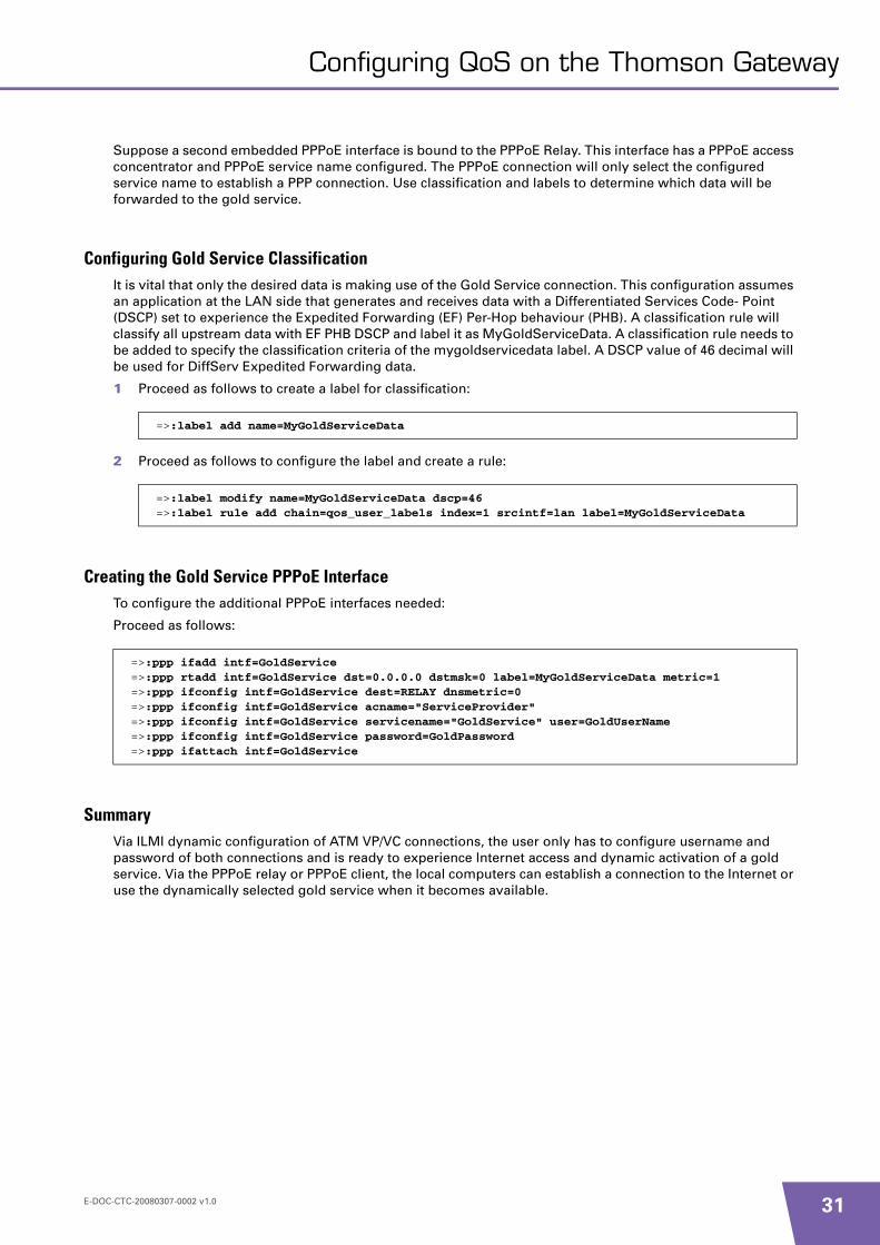
Suppose a second embedded PPPoE interface is bound to the PPPoE Relay. This interface has a PPPoE access concentrator and PPPoE service name configured. The PPPoE connection will only select the configured service name to establish a PPP connection. Use classification and labels to determine which data will be forwarded to the gold service.
Configuring Gold Service ClassificationIt is vital that only the desired data is making use of the Gold Service connection. This configuration assumes an application at the LAN side that generates and receives data with a Differentiated Services Code- Point (DSCP) set to experience the Expedited Forwarding (EF) Per-Hop behaviour (PHB). A classification rule will classify all upstream data with EF PHB DSCP and label it as MyGoldServiceData. A classification rule needs to be added to specify the classification criteria of the mygoldservicedata label. A DSCP value of 46 decimal will be used for DiffServ Expedited Forwarding data.
1 Proceed as follows to create a label for classification:
2 Proceed as follows to configure the label and create a rule:
Creating the Gold Service PPPoE InterfaceTo configure the additional PPPoE interfaces needed:
Proceed as follows:
SummaryVia ILMI dynamic configuration of ATM VP/VC connections, the user only has to configure username and password of both connections and is ready to experience Internet access and dynamic activation of a gold service. Via the PPPoE relay or PPPoE client, the local computers can establish a connection to the Internet or use the dynamically selected gold service when it becomes available.
=>:label add name=MyGoldServiceData
=>:label modify name=MyGoldServiceData dscp=46=>:label rule add chain=qos_user_labels index=1 srcintf=lan label=MyGoldServiceData
=>:ppp ifadd intf=GoldService=>:ppp rtadd intf=GoldService dst=0.0.0.0 dstmsk=0 label=MyGoldServiceData metric=1=>:ppp ifconfig intf=GoldService dest=RELAY dnsmetric=0=>:ppp ifconfig intf=GoldService acname="ServiceProvider"=>:ppp ifconfig intf=GoldService servicename="GoldService" user=GoldUserName=>:ppp ifconfig intf=GoldService password=GoldPassword=>:ppp ifattach intf=GoldService
E-DOC-CTC-20080307-0002 v1.0 31

32
Configuring QoS on the Thomson Gateway
3.4 Example: SOHO with Two Sites
IllustrationThis example covers a basic SOHO configuration with one main site and a remote site. Both sites are connected via a VBR-nrt category ATM connection, and the main site is connected to the service provider and to the Internet via an UBR category ATM connection. This QoS application guarantees the site-to-site data traffic and leaves HTTP data from the proxy or to the web-server best effort.
The main site has a local proxy server and a public web-server to host the SOHO website where customers can place order or trace their project progress. Local computers can only access the Internet via the local proxy server. There is no direct HTTP (or other) connectivity allowed from local computers to the Internet and all incoming HTTP requests from the Internet are forwarded to the internal web-server.
This is of course a simplified example that is easily extendable with e.g. a local mail-server or an additional UBR category ATM VC connection between the two SOHO sites for best-effort traffic (with ERP or real-time project collaboration tools using the VBR-nrt QoS category).
SpeedTouch Router 1
192.168.1.254/24
Proxy 192.168.1.2/24
PC11192.168.1.3/24
8*35 UBR
8*36 VBR-nrt
Internet Network
Webserver 192.168.1.1/24
PC12 192.168.2.1/24
SpeedTouch Router 2 192.168.1.254/24
PC21192.168.1.21/24
PC22 192.168.1.22/24
180.162.10.1/32
30.0.0.1/32
180.162.10.1/32
Main Site Local Network
Remote Site Local Network
E-DOC-CTC-20080307-0002 v1.0

Configuring QoS on the Thomson Gateway
QoS parametersThe UBR QoS category ATM connection is configured with PCR equal to line-rate. The VBR-nrt QoS category ATM connection is configured with PCR equal to 1152Kb/s, SCR equal to 576Kb/s and MBS equal to 3072bytes (64 ATM cells).
The connection towards the Internet is using an IPoA connection with a static IP address to host the web server.
The connection between the two sites is using IPoA but can in case of a Thomson Gateway 620/605/608(WL) be secured via IPSec.
The focus of this configuration example is on the Thomson Gateway Router 1 because this router has the most complicated configuration. Thomson Gateway Router 2 is DHCP server in the 193.168.1.0/24 network and has a default route pointing to the Thomson Gateway Router 1.
Creating Qosbook EntriesWe will now create the qosbook profiles needed for this example. Only the VBR-nrt entry will be added because the default profile is line-rate UBR.
1 Proceed as follows:
2 Proceed as follows to created two qosbook entries with the connection traffic descriptors:
Creating Phonebook and ATM EntriesCreate two ATM PVC connections.
Proceed as follows:
Creating IPoA InterfacesTwo IPoA interfaces will be created, the first one towards the remote SOHO site. A second IPoA interface towards the internet.
1 Proceed as follows to create the first IPoA interface:
=>:atm qosbook ctdadd name=VBR conformance=VBR peakrate=1152 sustrate=576 maxburst=3072
=>:atm qosbook add name=default txctd=default rxctd=default=>:atm qosbook add name=VBR txctd=VBR rxctd=VBR
=>:atm phonebook add name=SiteToSite addr=8*36=>:atm phonebook add name=Internet addr=8*35=>:atm ifadd intf=AtmSiteToSite=>:atm ifadd intf=AtmInternet=>:atm ifconfig intf=AtmSiteToSite dest=SiteToSite qos=VBR ulp=ip=>:atm ifconfig intf=AtmInternet dest=Internet qos=default ulp=ip=>:atm ifattach intf=AtmSiteToSite=>:atm ifattach intf=AtmInternet
=>:ip ifadd intf=SiteToSite dest=AtmSiteToSite=>:ip ipadd intf=SiteToSite addr=30.0.0.1 pointopoint=30.0.0.2 addroute=disabled=>:ip ifattach intf=SiteToSite
E-DOC-CTC-20080307-0002 v1.0 33
34
Configuring QoS on the Thomson Gateway
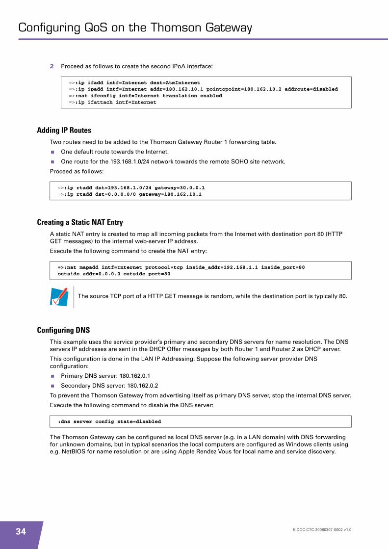
2 Proceed as follows to create the second IPoA interface:
Adding IP RoutesTwo routes need to be added to the Thomson Gateway Router 1 forwarding table.
One default route towards the Internet.
One route for the 193.168.1.0/24 network towards the remote SOHO site network.
Proceed as follows:
Creating a Static NAT EntryA static NAT entry is created to map all incoming packets from the Internet with destination port 80 (HTTP GET messages) to the internal web-server IP address.
Execute the following command to create the NAT entry:
Configuring DNSThis example uses the service provider’s primary and secondary DNS servers for name resolution. The DNS servers IP addresses are sent in the DHCP Offer messages by both Router 1 and Router 2 as DHCP server.
This configuration is done in the LAN IP Addressing. Suppose the following server provider DNS configuration:
Primary DNS server: 180.162.0.1
Secondary DNS server: 180.162.0.2
To prevent the Thomson Gateway from advertising itself as primary DNS server, stop the internal DNS server.
Execute the following command to disable the DNS server:
The Thomson Gateway can be configured as local DNS server (e.g. in a LAN domain) with DNS forwarding for unknown domains, but in typical scenarios the local computers are configured as Windows clients using e.g. NetBIOS for name resolution or are using Apple Rendez Vous for local name and service discovery.
=>:ip ifadd intf=Internet dest=AtmInternet=>:ip ipadd intf=Internet addr=180.162.10.1 pointopoint=180.162.10.2 addroute=disabled=>:nat ifconfig intf=Internet translation enabled=>:ip ifattach intf=Internet
=>:ip rtadd dst=193.168.1.0/24 gateway=30.0.0.1=>:ip rtadd dst=0.0.0.0/0 gateway=180.162.10.1
=>:nat mapadd intf=Internet protocol=tcp inside_addr=192.168.1.1 inside_port=80 outside_addr=0.0.0.0 outside_port=80
The source TCP port of a HTTP GET message is random, while the destination port is typically 80.
:dns server config state=disabled
E-DOC-CTC-20080307-0002 v1.0
Configuring QoS on the Thomson Gateway
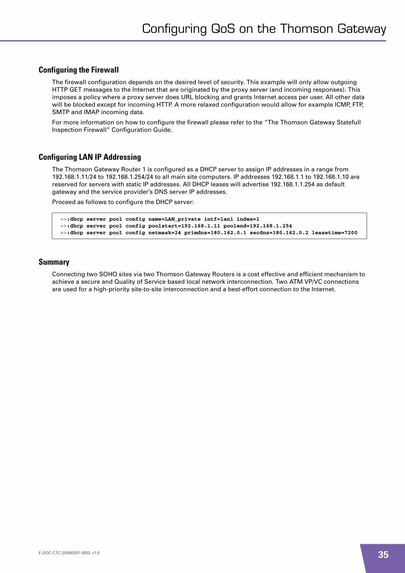
Configuring the FirewallThe firewall configuration depends on the desired level of security. This example will only allow outgoing HTTP GET messages to the Internet that are originated by the proxy server (and incoming responses). This imposes a policy where a proxy server does URL blocking and grants Internet access per user. All other data will be blocked except for incoming HTTP. A more relaxed configuration would allow for example ICMP, FTP, SMTP and IMAP incoming data.
For more information on how to configure the firewall please refer to the “The Thomson Gateway Statefull Inspection Firewall” Configuration Guide.
Configuring LAN IP AddressingThe Thomson Gateway Router 1 is configured as a DHCP server to assign IP addresses in a range from 192.168.1.11/24 to 192.168.1.254/24 to all main site computers. IP addresses 192.168.1.1 to 192.168.1.10 are reserved for servers with static IP addresses. All DHCP leases will advertise 192.168.1.1.254 as default gateway and the service provider’s DNS server IP addresses.
Proceed as follows to configure the DHCP server:
SummaryConnecting two SOHO sites via two Thomson Gateway Routers is a cost effective and efficient mechanism to achieve a secure and Quality of Service based local network interconnection. Two ATM VP/VC connections are used for a high-priority site-to-site interconnection and a best-effort connection to the Internet.
=>:dhcp server pool config name=LAN_private intf=lan1 index=1=>:dhcp server pool config poolstart=192.168.1.11 poolend=192.168.1.254=>:dhcp server pool config netmask=24 primdns=180.162.0.1 secdns=180.162.0.2 leasetime=7200
E-DOC-CTC-20080307-0002 v1.0 35

36
Configuring QoS on the Thomson Gateway
E-DOC-CTC-20080307-0002 v1.0


THOMSON Telecom BelgiumPrins Boudewijnlaan 472650 Edegem
www.thomson-broadband.com
© THOMSON 2008. All rights reserved.E-DOC-CTC-20080307-0002 v1.0.


