Config Guide Mpls Applications
548
JUNOS® Software MPLS Applications Configuration Guide Release 9.6 Juniper Networks, Inc. 1194 North Mathilda Avenue Sunnyvale, California 94089 USA 408-745-2000 www.juniper.net Published: 2009-07-22
-
Upload
overone1984 -
Category
Documents
-
view
235 -
download
0
Transcript of Config Guide Mpls Applications

8/7/2019 Config Guide Mpls Applications
http://slidepdf.com/reader/full/config-guide-mpls-applications 1/547
JUNOS® Software
MPLS Applications Configuration Guide
Release 9.6
Juniper Networks, Inc.1194 North Mathilda Avenue
Sunnyvale, California 94089
USA
408-745-2000
www.juniper.net
Published: 2009-07-22

8/7/2019 Config Guide Mpls Applications
http://slidepdf.com/reader/full/config-guide-mpls-applications 2/547
This product includes the Envoy SNMP Engine, developed by Epilogue Technology, an Integrated Systems Company. Copyright © 1986-1997, EpilogueTechnology Corporation. All rights reserved. This program and i ts documentation were developed at private expense, and no part of them is in the publicdomain.
This product includes memory allocation software developed by Mark Moraes, copyright © 1988, 1989, 1993, University of Toronto.
This product includes FreeBSD software developed by the University of California, Berkeley, and its contributors. All of the documentation and softwareincluded in the 4.4BSD and 4.4BSD-Lite Releases is copyrighted by the Regents of the University of California. Copyright © 1979, 1980, 1983, 1986, 1988,1989, 1991, 1992, 1993, 1994. The Regents of the University of California. All rights reserved.
GateD software copyright © 1995, the Regents of the University. All rights reserved. Gate Daemon was originated and developed through release 3.0 byCornell University and its collaborators. Gated is based on Kirton’s EGP, UC Berkeley’s routing daemon (routed), and DCN’s HELLO routing protocol.Development of Gated has been supported in part by the National Science Foundation. Portions of the GateD software copyright © 1988, Regents of theUniversity of California. All rights reserved. Portions of the GateD software copyright © 1991, D. L. S. Associates.
This product includes software developed by Maker Communications, Inc., copyright © 1996, 1997, Maker Communications, Inc.
Juniper Networks, the Juniper Networks logo, JUNOS, NetScreen, ScreenOS, and Steel-Belted Radius are registered trademarks of Juniper Networks, Inc. inthe United States and other countries. JUNOSe is a trademark of Juniper Networks, Inc. All other trademarks, service marks, registered trademarks, orregistered service marks are the property of their respective owners.
Juniper Networks assumes no responsibility for any inaccuracies in this document. Juniper Networks reserves the right to change, modify, transfer, orotherwise revise this publication without notice.
Products made or sold by Juniper Networks or components thereof might be covered by one or more of the following patents that are owned by or licensedto Juniper Networks: U.S. Patent Nos. 5,473,599, 5,905,725, 5,909,440, 6,192,051, 6,333,650, 6,359,479, 6,406,312, 6,429,706, 6,459,579, 6,493,347,6,538,518, 6,538,899, 6,552,918, 6,567,902, 6,578,186, and 6,590,785.
JUNOS® Software MPLS Applications Configuration Guide
Release 9.6Copyright © 2009, Juniper Networks, Inc.All rights reserved. Printed in USA.
Writing: Albert StattiEditing: Sonia Saruba, Laura SingerIllustration: Nathaniel WoodwardCover Design: Edmonds Design
Revision History July 2009—R1 JUNOS 9.6
The information in this document is current as of the date listed in the revision history.
YEAR 2000 NOTICE
Juniper Networks hardware and software products are Year 2000 compliant. The JUNOS Software has no known time-related limitations through the year2038. However, the NTP application is known to have some difficulty in the year 2036.
ii ■

8/7/2019 Config Guide Mpls Applications
http://slidepdf.com/reader/full/config-guide-mpls-applications 3/547
END USER LICENSE AGREEMENT
READ THIS END USER LICENSE AGREEMENT (“AGREEMENT”) BEFORE DOWNLOADING, INSTALLING, OR USING THE SOFTWARE. BY DOWNLOADING,INSTALLING, OR USING THE SOFTWARE OR OTHERWISE EXPRESSING YOUR AGREEMENT TO THE TERMS CONTAINED HEREIN, YOU (AS CUSTOMEROR IF YOU ARE NOT THE CUSTOMER, AS A REPRESENTATIVE/AGENT AUTHORIZED TO BIND THE CUSTOMER) CONSENT TO BE BOUND BY THIS
AGREEMENT. IF YOU DO NOT OR CANNOT AGREE TO THE TERMS CONTAINED HEREIN, THEN (A) DO NOT DOWNLOAD, INSTALL, OR USE THE SOFTWARE,AND (B) YOU MAY CONTACT JUNIPER NETWORKS REGARDING LICENSE TERMS.
1. The Parties. The parties to this Agreement are (i) Juniper Networks, Inc. (if the Customer’s principal office is located in the Americas) or Juniper Networks(Cayman) Limited (if the Customer’s principal office is located outside the Americas) (such applicable entity being referred to herein as “ Juniper”), and (ii)the person or organization that originally purchased from Juniper or an authorized Juniper reseller the applicable license(s) for use of the Software (“Customer”)(collectively, the “Parties”).
2. The Software. In this Agreement, “Software” means the program modules and features of the Juniper or Juniper-supplied software, for which Customerhas paid the applicable license or support fees to Juniper or an authorized Juniper reseller, or which was embedded by Juniper in equipment which Customerpurchased from Juniper or an authorized Juniper reseller. “Software” also includes updates, upgrades and new releases of such software. “EmbeddedSoftware” means Software which Juniper has embedded in or loaded onto the Juniper equipment and any updates, upgrades, additions or replacementswhich are subsequently embedded in or loaded onto the equipment.
3. License Grant. Subject to payment of the applicable fees and the limitations and restrictions set forth herein, Juniper grants to Customer a non-exclusiveand non-transferable license, without right to sublicense, to use the Software, in executable form only, subject to the following use restrictions:
a. Customer shall use Embedded Software solely as embedded in, and for execution on, Juniper equipment originally purchased by Customer from Juniperor an authorized Juniper reseller.
b. Customer shall use the Software on a single hardware chassis having a single processing unit, or as many chassis or processing units for which Customerhas paid the applicable license fees; provided, however, with respect to the Steel-Belted Radius or Odyssey Access Client software only, Customer shall usesuch Software on a single computer containing a single physical random access memory space and containing any number of processors. Use of theSteel-Belted Radius or IMS AAA software on multiple computers or virtual machines (e.g., Solaris zones) requires multiple licenses, regardless of whethersuch computers or virtualizations are physically contained on a single chassis.
c. Product purchase documents, paper or electronic user documentation, and/or the particular licenses purchased by Customer may specify limits toCustomer’s use of the Software. Such limits may restrict use to a maximum number of seats, registered endpoints, concurrent users, sessions, calls,connections, subscribers, clusters, nodes, realms, devices, links, ports or transactions, or require the purchase of separate licenses to use particular features,functionalities, services, applications, operations, or capabilities, or provide throughput, performance, configuration, bandwidth, interface, processing,temporal, or geographical limits. In addition, such limits may restrict the use of the Software to managing certain kinds of networks or require the Softwareto be used only in conjunction with other specific Software. Customer’s use of the Software shall be subject to all such limitations and purchase of all applicablelicenses.
d. For any trial copy of the Software, Customer’s right to use the Software expires 30 days after download, installation or use of the Software. Customermay operate the Software after the 30-day trial period only if Customer pays for a license to do so. Customer may not extend or create an additional trialperiod by re-installing the Software after the 30-day trial period.
e. The Global Enterprise Edition of the Steel-Belted Radius software may be used by Customer only to manage access to Customer’s enterprise network.Specifically, service provider customers are expressly prohibited from using the Global Enterprise Edition of the Steel-Belted Radius software to support anycommercial network access services.
The foregoing license is not transferable or assignable by Customer. No license is granted herein to any user who did not originally purchase the applicablelicense(s) for the Software from Juniper or an authorized Juniper reseller.
4. Use Prohibitions. Notwithstanding the foregoing, the license provided herein does not permit the Customer to, and Customer agrees not to and shallnot: (a) modify, unbundle, reverse engineer, or create derivative works based on the Software; (b) make unauthorized copies of the Software (except asnecessary for backup purposes); (c) rent, sell, transfer, or grant any rights in and to any copy of the Software, in any form, to any third party; (d) removeany proprietary notices, labels, or marks on or in any copy of the Software or any product in which the Software is embedded; (e) dist ribute any copy of the Software to any third party, including as may be embedded in Juniper equipment sold in the secondhand market; (f) use any ‘locked’ or key-restricted
feature, function, service, application, operation, or capability without first purchasing the applicable license(s) and obtaining a valid key from Juniper, evenif such feature, function, service, application, operation, or capability is enabled without a key; (g) distribute any key for the Software provided by Juniperto any third party; (h) use the Software in any manner that extends or is broader than the uses purchased by Customer from Juniper or an authorized Juniperreseller; (i) use Embedded Software on non-Juniper equipment; (j) use Embedded Software (or make it available for use) on Juniper equipment that theCustomer did not originally purchase from Juniper or an authorized Juniper reseller; (k) disclose the results of testing or benchmarking of the Software toany third party without the prior written consent of Juniper; or (l) use the Software in any manner other than as expressly provided herein.
5. Audit. Customer shall maintain accurate records as necessary to verify compliance with this Agreement. Upon request by Juniper, Customer shall furnishsuch records to Juniper and certify its compliance with this Agreement.
■ iii
8/7/2019 Config Guide Mpls Applications
http://slidepdf.com/reader/full/config-guide-mpls-applications 4/547
6. Confidentiality. The Parties agree that aspects of the Software and associated documentation are the confidential property of Juniper. As such, Customershall exercise all reasonable commercial efforts to maintain the Software and associated documentation in confidence, which at a minimum includesrestricting access to the Software to Customer employees and contractors having a need to use the Software for Customer’s internal business purposes.
7. Ownership. Juniper and Juniper’s licensors, respectively, retain ownership of all right, title, and interest (including copyright) in and to the Software,
associated documentation, and all copies of the Software. Nothing in this Agreement constitutes a transfer or conveyance of any right, title, or interest inthe Software or associated documentation, or a sale of the Software, associated documentation, or copies of the Software.
8. Warranty, Limitation of Liability, Disclaimer of Warranty. The warranty applicable to the Software shall be as set forth in the warranty statement thataccompanies the Software (the “Warranty Statement”). Nothing in this Agreement shall give rise to any obligation to support the Software. Support servicesmay be purchased separately. Any such support shall be governed by a separate, written support services agreement. TO THE MAXIMUM EXTENT PERMITTEDBY LAW, JUNIPER SHALL NOT BE LIABLE FOR ANY LOST PROFITS, LOSS OF DATA, OR COSTS OR PROCUREMENT OF SUBSTITUTE GOODS OR SERVICES,OR FOR ANY SPECIAL, INDIRECT, OR CONSEQUENTIAL DAMAGES ARISING OUT OF THIS AGREEMENT, THE SOFTWARE, OR ANY JUNIPER OR JUNIPER-SUPPLIED SOFTWARE. IN NO EVENT SHALL JUNIPER BE LIABLE FOR DAMAGES ARISING FROM UNAUTHORIZED OR IMPROPER USE OF ANY JUNIPER OR JUNIPER-SUPPLIED SOFTWARE. EXCEPT AS EXPRESSLY PROVIDED IN THE WARRANTY STATEMENT TO THE EXTENT PERMITTED BY LAW, JUNIPER DISCLAIMS ANY AND ALL WARRANTIES IN AND TO THE SOFTWARE (WHETHER EXPRESS, IMPLIED, STATUTORY, OR OTHERWISE), INCLUDINGANY IMPLIED WARRANTY OF MERCHANTABILITY, FITNESS FOR A PARTICULAR PURPOSE, OR NONINFRINGEMENT. IN NO EVENT DOES JUNIPERWARRANT THAT THE SOFTWARE, OR ANY EQUIPMENT OR NETWORK RUNNING THE SOFTWARE, WILL OPERATE WITHOUT ERROR OR INTERRUPTION,OR WILL BE FREE OF VULNERABILITY TO INTRUSION OR ATTACK. In no event shall Juniper’s or its suppliers’ or licensors’ liability to Customer, whetherin contract, tort (including negligence), breach of warranty, or otherwise, exceed the price paid by Customer for the Software that gave rise to the claim, orif the Software is embedded in another Juniper product, the price paid by Customer for such other product. Customer acknowledges and agrees that Juniperhas set its prices and entered into this Agreement in reliance upon the disclaimers of warranty and the limitations of liability set forth herein, that the same
reflect an allocation of risk between the Parties (including the risk that a contract remedy may fail of its essential purpose and cause consequential loss),and that the same form an essential basis of the bargain between the Parties.
9. Termination. Any breach of this Agreement or failure by Customer to pay any applicable fees due shall result in automatic termination of the licensegranted herein. Upon such termination, Customer shall destroy or return to Juniper all copies of the Software and related documentation in Customer’spossession or control.
10. Taxes. All license fees payable under this agreement are exclusive of tax. Customer shall be responsible for paying Taxes arising from the purchase of the license, or importation or use of the Software. If applicable, valid exemption documentation for each taxing jurisdiction shall be provided to Juniper priorto invoicing, and Customer shall promptly notify Juniper if their exemption is revoked or modified. All payments made by Customer shall be net of anyapplicable withholding tax. Customer will provide reasonable assistance to Juniper in connection with such withholding taxes by promptly: providing Juniperwith valid tax receipts and other required documentation showing Customer’s payment of any withholding taxes; completing appropriate applications thatwould reduce the amount of withholding tax to be paid; and notifying and assisting Juniper in any audit or tax proceeding related to transactions hereunder.Customer shall comply with all applicable tax laws and regulations, and Customer will promptly pay or reimburse Juniper for all costs and damages relatedto any liability incurred by Juniper as a result of Customer’s non-compliance or delay with its responsibilities herein. Customer’s obligations under thisSection shall survive termination or expiration of this Agreement.
11. Export. Customer agrees to comply with all applicable export laws and restrictions and regulations of any United States and any applicable foreignagency or authority, and not to export or re-export the Software or any direct product thereof in violation of any such restrictions, laws or regulations, orwithout all necessary approvals. Customer shall be liable for any such violations. The version of the Software supplied to Customer may contain encryptionor other capabilities restricting Customer’s ability to export the Software without an export license.
12. Commercial Computer Software. The Software is “commercial computer software” and is provided with restricted rights. Use, duplication, or disclosureby the United States government is subject to restrictions set forth in this Agreement and as provided in DFARS 227.7201 through 227.7202-4, FAR 12.212,FAR 27.405(b)(2), FAR 52.227-19, or FAR 52.227-14(ALT III) as applicable.
13. Interface Information. To the extent required by applicable law, and at Customer's written request, Juniper shall provide Customer with the interfaceinformation needed to achieve interoperability between the Software and another independently created program, on payment of applicable fee, if any.Customer shall observe strict obligations of confidentiality with respect to such information and shall use such information in compliance with any applicableterms and conditions upon which Juniper makes such information available.
14. Third Party Software. Any licensor of Juniper whose software is embedded in the Software and any supplier of Juniper whose products or technologyare embedded in (or services are accessed by) the Software shall be a third party beneficiary with respect to this Agreement, and such licensor or vendor
shall have the right to enforce this Agreement in its own name as if it were Juniper. In addition, certain third party software may be provided with theSoftware and is subject to the accompanying license(s), if any, of its respective owner(s). To the extent portions of the Software are distributed under andsubject to open source licenses obligating Juniper to make the source code for such portions publicly available (such as the GNU General Public License(“GPL”) or the GNU Library General Public License (“LGPL”)), Juniper will make such source code portions (including Juniper modifications, as appropriate)available upon request for a period of up to three years from the date of distribution. Such request can be made in writing to Juniper Networks, Inc., 1194
N. Mathilda Ave., Sunnyvale, CA 94089, ATTN: General Counsel. You may obtain a copy of the GPL at http://www.gnu.org/licenses/gpl.html, and
a copy of the LGPL at http://www.gnu.org/licenses/lgpl.html.
15. Miscellaneous.This Agreement shall be governed by the laws of the State of California without reference to its conflicts of laws principles. The provisionsof the U.N. Convention for the International Sale of Goods shall not apply to this Agreement. For any disputes arising under this Agreement, the Partieshereby consent to the personal and exclusive jurisdiction of, and venue in, the state and federal courts within Santa Clara County, California. This Agreementconstitutes the entire and sole agreement between Juniper and the Customer with respect to the Software, and supersedes all prior and contemporaneous
iv ■

8/7/2019 Config Guide Mpls Applications
http://slidepdf.com/reader/full/config-guide-mpls-applications 5/547
agreements relating to the Software, whether oral or written (including any inconsistent terms contained in a purchase order), except that the terms of aseparate written agreement executed by an authorized Juniper representative and Customer shall govern to the extent such terms are inconsistent or conflictwith terms contained herein. No modification to this Agreement nor any waiver of any rights hereunder shall be effective unless expressly assented to inwriting by the party to be charged. If any portion of this Agreement is held invalid, the Parties agree that such invalidity shall not affect the validity of theremainder of this Agreement. This Agreement and associated documentation has been written in the English language, and the Parties agree that the English
version will govern. (For Canada: Les parties aux présentés confirment leur volonté que cette convention de même que tous les documents y compris toutavis qui s'y rattaché, soient redigés en langue anglaise. (Translation: The parties confirm that this Agreement and all related documentation is and will bein the English language)).
■ v

8/7/2019 Config Guide Mpls Applications
http://slidepdf.com/reader/full/config-guide-mpls-applications 6/547
vi ■

8/7/2019 Config Guide Mpls Applications
http://slidepdf.com/reader/full/config-guide-mpls-applications 7/547
Abbreviated Table of Contents
About This Guide xxxi
Part 1 Overview
Chapter 1 Traffic Engineering Overview 3
Chapter 2 Complete MPLS Applications Configuration Statements 9
Part 2 MPLS
Chapter 3 MPLS Overview 21
Chapter 4 MPLS Router Configuration Guidelines 51
Chapter 5 MPLS-Signaled LSP Configuration Guidelines 69
Chapter 6 DiffServ-Aware Traffic Engineering Configuration Guidelines 109
Chapter 7 Static and Explicit-Path LSP Configuration Guidelines 133
Chapter 8 Point-to-Multipoint LSP Configuration Guidelines 141
Chapter 9 Miscellaneous MPLS Properties Configuration Guidelines 149
Chapter 10 Summary of MPLS Configuration Statements 173
Part 3 RSVPChapter 11 RSVP Overview 255
Chapter 12 RSVP Configuration Guidelines 273
Chapter 13 Summary of RSVP Configuration Statements 299
Part 4 LDP
Chapter 14 LDP Overview 329
Chapter 15 LDP Configuration Guidelines 337
Chapter 16 Summary of LDP Configuration Statements 367
Part 5 CCC and TCC
Chapter 17 CCC and TCC Overview 401
Chapter 18 CCC and TCC Configuration Guidelines 405
Chapter 19 Summary of CCC and TCC Configuration Statements 427
Part 6 GMPLS
Chapter 20 GMPLS Overview 443
Abbreviated Table of Contents ■ vii

8/7/2019 Config Guide Mpls Applications
http://slidepdf.com/reader/full/config-guide-mpls-applications 8/547
Chapter 21 GMPLS Configuration Guidelines 449
Chapter 22 Hierarchy of RSVP LSPs Configuration Guidelines 465
Chapter 23 Summary of GMPLS Configuration Statements 471
Part 7 Indexes
Index 491
Index of Statements and Commands 507
viii ■
JUNOS 9.6 MPLS Applications Configuration Guide
8/7/2019 Config Guide Mpls Applications
http://slidepdf.com/reader/full/config-guide-mpls-applications 9/547
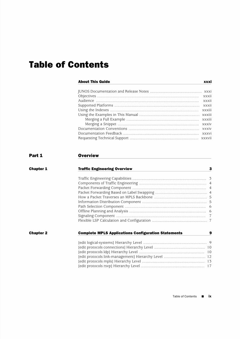
Table of Contents
About This Guide xxxi
JUNOS Documentation and Release Notes .................................................. xxxiObjectives .................................................................................................. xxxiiAudience ................................................................................................... xxxiiSupported Platforms .................................................................................. xxxiiUsing the Indexes ..................................................................................... xxxiiiUsing the Examples in This Manual .......................................................... xxxiii
Merging a Full Example ...................................................................... xxxiiiMerging a Snippet .............................................................................. xxxiv
Documentation Conventions .................................................................... xxxivDocumentation Feedback ......................................................................... xxxviRequesting Technical Support .................................................................. xxxvii
Part 1 Overview
Chapter 1 Traffic Engineering Overview 3
Traffic Engineering Capabilities ....................................................................... 3Components of Traffic Engineering ................................................................. 4Packet Forwarding Component ....................................................................... 4Packet Forwarding Based on Label Swapping .................................................. 4How a Packet Traverses an MPLS Backbone ................................................... 5Information Distribution Component .............................................................. 5Path Selection Component .............................................................................. 6Offline Planning and Analysis .......................................................................... 6Signaling Component ...................................................................................... 7Flexible LSP Calculation and Configuration ..................................................... 7
Chapter 2 Complete MPLS Applications Configuration Statements 9
[edit logical-systems] Hierarchy Level ............................................................. 9[edit protocols connections] Hierarchy Level ................................................. 10[edit protocols ldp] Hierarchy Level ............................................................... 10[edit protocols link-management] Hierarchy Level ........................................ 12[edit protocols mpls] Hierarchy Level ............................................................ 13[edit protocols rsvp] Hierarchy Level ............................................................. 17
Table of Contents ■ ix
8/7/2019 Config Guide Mpls Applications
http://slidepdf.com/reader/full/config-guide-mpls-applications 10/547
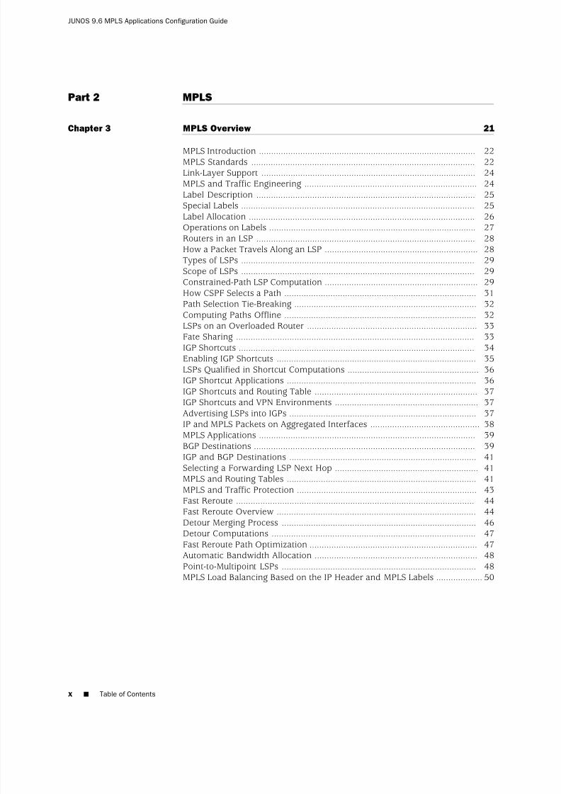
Part 2 MPLS
Chapter 3 MPLS Overview 21
MPLS Introduction ......................................................................................... 22MPLS Standards ............................................................................................ 22Link-Layer Support ........................................................................................ 24MPLS and Traffic Engineering ....................................................................... 24Label Description .......................................................................................... 25Special Labels ................................................................................................ 25Label Allocation ............................................................................................. 26Operations on Labels ..................................................................................... 27Routers in an LSP .......................................................................................... 28How a Packet Travels Along an LSP ............................................................... 28Types of LSPs ................................................................................................ 29Scope of LSPs ................................................................................................ 29Constrained-Path LSP Computation ............................................................... 29How CSPF Selects a Path ............................................................................... 31Path Selection Tie-Breaking ........................................................................... 32Computing Paths Offline ............................................................................... 32LSPs on an Overloaded Router ...................................................................... 33Fate Sharing .................................................................................................. 33IGP Shortcuts ................................................................................................. 34Enabling IGP Shortcuts .................................................................................. 35LSPs Qualified in Shortcut Computations ...................................................... 36IGP Shortcut Applications .............................................................................. 36IGP Shortcuts and Routing Table ................................................................... 37IGP Shortcuts and VPN Environments ........................................................... 37
Advertising LSPs into IGPs ............................................................................. 37IP and MPLS Packets on Aggregated Interfaces ............................................. 38MPLS Applications ......................................................................................... 39BGP Destinations ........................................................................................... 39IGP and BGP Destinations ............................................................................. 41Selecting a Forwarding LSP Next Hop ........................................................... 41MPLS and Routing Tables .............................................................................. 41MPLS and Traffic Protection .......................................................................... 43Fast Reroute .................................................................................................. 44Fast Reroute Overview .................................................................................. 44Detour Merging Process ................................................................................ 46Detour Computations .................................................................................... 47Fast Reroute Path Optimization ..................................................................... 47
Automatic Bandwidth Allocation ................................................................... 48Point-to-Multipoint LSPs ................................................................................ 48MPLS Load Balancing Based on the IP Header and MPLS Labels ...................50
x ■ Table of Contents
JUNOS 9.6 MPLS Applications Configuration Guide
8/7/2019 Config Guide Mpls Applications
http://slidepdf.com/reader/full/config-guide-mpls-applications 11/547
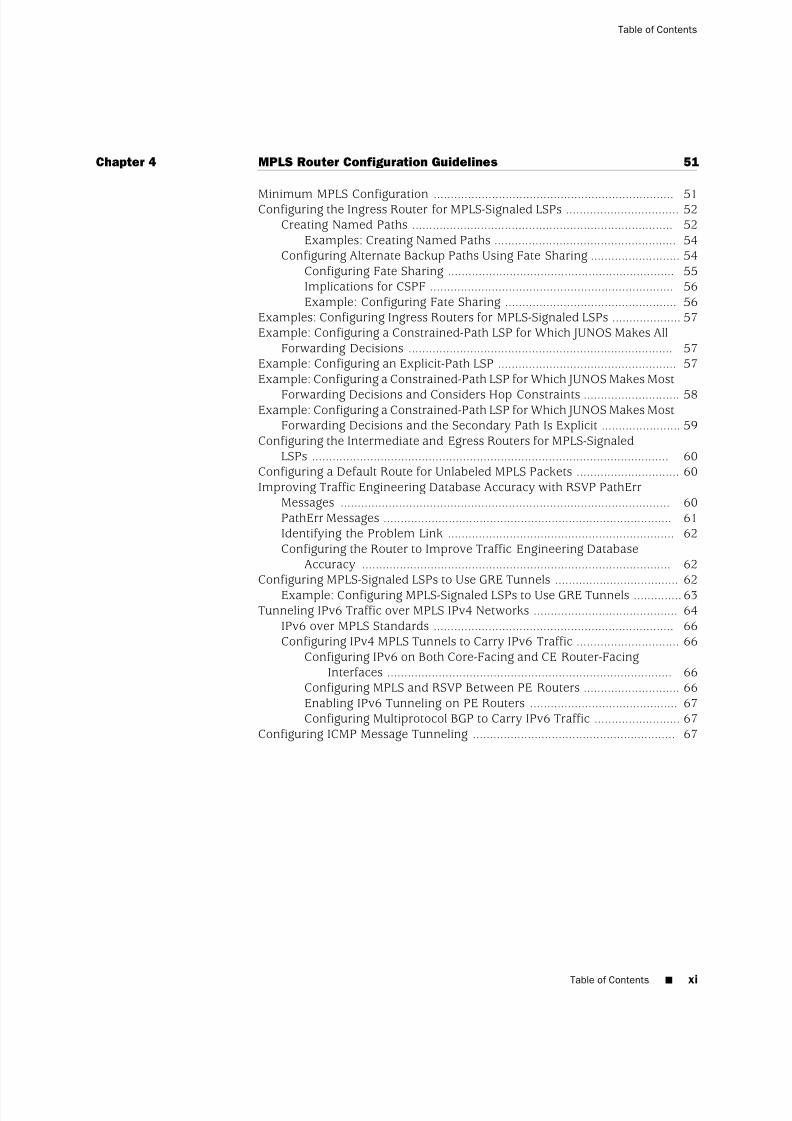
Chapter 4 MPLS Router Configuration Guidelines 51
Minimum MPLS Configuration ...................................................................... 51Configuring the Ingress Router for MPLS-Signaled LSPs ................................. 52Creating Named Paths ............................................................................ 52
Examples: Creating Named Paths ..................................................... 54Configuring Alternate Backup Paths Using Fate Sharing .......................... 54
Configuring Fate Sharing .................................................................. 55Implications for CSPF ....................................................................... 56Example: Configuring Fate Sharing .................................................. 56
Examples: Configuring Ingress Routers for MPLS-Signaled LSPs .................... 57Example: Configuring a Constrained-Path LSP for Which JUNOS Makes All
Forwarding Decisions ............................................................................. 57Example: Configuring an Explicit-Path LSP .................................................... 57Example: Configuring a Constrained-Path LSP for Which JUNOS Makes Most
Forwarding Decisions and Considers Hop Constraints ............................ 58Example: Configuring a Constrained-Path LSP for Which JUNOS Makes Most
Forwarding Decisions and the Secondary Path Is Explicit ....................... 59Configuring the Intermediate and Egress Routers for MPLS-Signaled
LSPs ........................................................................................................ 60Configuring a Default Route for Unlabeled MPLS Packets .............................. 60Improving Traffic Engineering Database Accuracy with RSVP PathErr
Messages ................................................................................................ 60PathErr Messages .................................................................................... 61Identifying the Problem Link .................................................................. 62Configuring the Router to Improve Traffic Engineering Database
Accuracy .......................................................................................... 62Configuring MPLS-Signaled LSPs to Use GRE Tunnels .................................... 62
Example: Configuring MPLS-Signaled LSPs to Use GRE Tunnels ..............63Tunneling IPv6 Traffic over MPLS IPv4 Networks .......................................... 64
IPv6 over MPLS Standards ...................................................................... 66Configuring IPv4 MPLS Tunnels to Carry IPv6 Traffic .............................. 66
Configuring IPv6 on Both Core-Facing and CE Router-FacingInterfaces ................................................................................... 66
Configuring MPLS and RSVP Between PE Routers ............................ 66Enabling IPv6 Tunneling on PE Routers ........................................... 67Configuring Multiprotocol BGP to Carry IPv6 Traffic ......................... 67
Configuring ICMP Message Tunneling ........................................................... 67
Table of Contents ■ xi
Table of Contents

8/7/2019 Config Guide Mpls Applications
http://slidepdf.com/reader/full/config-guide-mpls-applications 12/547
Chapter 5 MPLS-Signaled LSP Configuration Guidelines 69
LSP Configuration Overview .......................................................................... 70Configuring the Ingress and Egress Router Addresses for LSPs ...................... 73Configuring the Ingress Router Address for LSPs .................................... 73Configuring the Egress Router Address for LSPs ..................................... 74Preventing the Addition of Egress Router Addresses to Routing
Tables ............................................................................................... 74Configuring Primary and Secondary LSPs ..................................................... 75
Configuring Primary and Secondary Paths for an LSP ............................. 75Configuring the Revert Timer for LSPs .................................................... 76Specifying the Conditions for Path Selection ........................................... 77
Configuring a Text Description for LSPs ........................................................ 78Configuring Fast Reroute ............................................................................... 78Configuring the Optimization Interval for Fast Reroute Paths ........................ 79
Adding LSP-Related Routes to the inet.3 Routing Table ................................. 80Configuring the Connection Between Ingress and Egress Routers .................81Configuring LSP Metrics ................................................................................ 82
Configuring Dynamic LSP Metrics ........................................................... 82Configuring Static LSP Metrics ................................................................ 82
Configuring CSPF Tie Breaking ...................................................................... 83Configuring Load Balancing for MPLS LSPs ................................................... 84
Using the First MPLS Label in the Hash Key ............................................ 84Using the Second MPLS Label in the Hash Key ....................................... 84Using the Third MPLS Label in the Hash Key .......................................... 85Using the IP Payload in the Hash Key ..................................................... 85Using the First Two Labels and the IP Payload in the Hash Key ..............85Configuring Load Balancing for MPLS LSPs Without CSPF ...................... 86
Disabling Normal TTL Decrementing ............................................................. 86Configuring MPLS Soft Preemption ............................................................... 87Configuring Automatic Bandwidth Allocation for LSPs ................................... 88
Configuring MPLS Statistics for Automatic Bandwidth Allocation ............89Configuring Automatic Bandwidth Allocation on LSPs ............................ 89
Configuring the Automatic Bandwidth Allocation Interval ................90Configuring the Maximum and Minimum Bounds of the LSP’s
Bandwidth ................................................................................. 90Configuring the Automatic Bandwidth Adjustment Threshold ..........91Configuring a Limit on Bandwidth Overflow Samples ....................... 91Configuring Passive Bandwidth Utilization Monitoring ..................... 93
Requesting Automatic Bandwidth Allocation Adjustment ........................ 94
Disabling Constrained-Path LSP Computation ............................................... 95Configuring Administrative Groups ................................................................ 96Configuring Preference Values for LSPs ......................................................... 98Disabling Path Route Recording .................................................................... 98Configuring Class of Service for MPLS LSPs ................................................... 98
Class of Service for MPLS Overview ........................................................ 99Configuring the MPLS CoS Bits ................................................................ 99Rewriting IEEE 802.1p Packet Headers with the MPLS CoS Value .........100
Configuring Adaptive LSPs .......................................................................... 101
xii ■ Table of Contents
JUNOS 9.6 MPLS Applications Configuration Guide

8/7/2019 Config Guide Mpls Applications
http://slidepdf.com/reader/full/config-guide-mpls-applications 13/547
Configuring Priority and Preemption for LSPs ............................................. 102Optimizing Signaled LSPs ............................................................................ 103Configuring the Smart Optimize Timer ........................................................ 105Limiting the Number of Hops in LSPs .......................................................... 105
Configuring the Bandwidth Value for LSPs .................................................. 106Configuring Hot Standby of Secondary Paths .............................................. 106Damping Advertisement of LSP State Changes ............................................ 107
Chapter 6 DiffServ-Aware Traffic Engineering Configuration Guidelines 109
DiffServ-Aware Traffic Engineering Introduction .........................................110DiffServ-Aware Traffic Engineering Standards ............................................. 110DiffServ-Aware Traffic Engineering Overview .............................................. 112DiffServ-Aware Traffic Engineering Features ...............................................112DiffServ-Aware Traffic Engineered LSPs ...................................................... 113DiffServ-Aware Traffic Engineered LSPs Overview ...................................... 113
DiffServ-Aware Traffic Engineered LSPs Operation ...................................... 113Multiclass LSPs ............................................................................................ 114Multiclass LSP Overview .............................................................................. 114Establishing a Multiclass LSP on the Differentiated Services Domain ...........115Configuring Routers for DiffServ-Aware Traffic Engineering ........................115
Configuring the Bandwidth Model .........................................................116Configuring Traffic Engineering Classes ................................................ 117
Requirements and Limitations for the Traffic Engineering ClassMatrix ...................................................................................... 118
Configuring Class of Service for Diffserv-Aware Traffic Engineering ......119Bandwidth Oversubscription Overview .......................................................119LSP Size Oversubscription ........................................................................... 120Link Size Oversubscription .......................................................................... 120Class Type Oversubscription and Local Oversubscription Multipliers ...........121Class Type Bandwidth and the LOM ............................................................ 121LOM Calculation for the MAM and Extended MAM Bandwidth Models ........122LOM Calculation for the Russian Dolls Bandwidth Model ............................. 122Example: LOM Calculation .......................................................................... 122Configuring the Bandwidth Subscription Percentage for LSPs ..................... 124
Constraints on Configuring Bandwidth Subscription .............................125Configuring LSPs for DiffServ-Aware Traffic Engineering ............................. 125
Configuring Class of Service for the Interfaces ...................................... 126Configuring IGP ..................................................................................... 126Configuring Traffic-Engineered LSPs ..................................................... 127Configuring Policing for LSPs ................................................................ 127
Configuring Fast Reroute for Traffic-Engineered LSPs ........................... 128Configuring Multiclass LSPs .........................................................................128Configuring Class of Service for the Interfaces ...................................... 129Configuring the IGP ............................................................................... 129Configuring Class-Type Bandwidth Constraints for Multiclass LSPs .......129Configuring Policing for Multiclass LSPs ................................................ 131Configuring Fast Reroute for Multiclass LSPs ........................................ 131
Table of Contents ■ xiii
Table of Contents
8/7/2019 Config Guide Mpls Applications
http://slidepdf.com/reader/full/config-guide-mpls-applications 14/547
Chapter 7 Static and Explicit-Path LSP Configuration Guidelines 133
Configuring Static LSPs ................................................................................ 133Configuring the Ingress Router for Static LSPs ...................................... 133Example: Configuring the Ingress Router .......................................135
Configuring the Intermediate and Egress Routers for Static LSPs ..........136Example: Configuring an Intermediate Router ...............................137Example: Configuring an Egress Router .........................................138
Configuring Static Unicast Routes for Point-to-Multipoint LSPs ..............138Configuring Explicit-Path LSPs ..................................................................... 140
Chapter 8 Point-to-Multipoint LSP Configuration Guidelines 141
Configuring Primary and Branch LSPs for Point-to-Multipoint LSPs .............141
Configuring the Primary Point-to-Multipoint LSP ...................................141Configuring a Branch LSP for Point-to-Multipoint LSPs .......................... 142Configuring the Branch LSP as a Dynamic Path .............................. 142Configuring the Branch LSP as a Static Path ...................................143
Example: Configuring a Point-to-Multipoint LSP .......................................... 143Configuring Link Protection for Point-to-Multipoint LSPs ............................. 144Configuring Graceful Restart for Point-to-Multipoint LSPs ............................ 144Configuring a Multicast RPF Check Policy for Point-to-Multipoint LSPs ........145
Example: Configuring Multicast RPF Check Policy for a Point-to-MultipointLSP ................................................................................................. 146
Configuring Ingress PE Router Redundancy for Point-to-Multipoint LSPs .....146Enabling Point-to-Point LSPs to Monitor Egress PE Routers ......................... 147Preserving Point-to-Multipoint LSP Functioning with Different JUNOS Software
Releases ................................................................................................ 147
Chapter 9 Miscellaneous MPLS Properties Configuration Guidelines 149
Configuring MPLS to Pop the Label on the Ultimate-Hop Router .................149Configuring Traffic Engineering for LSPs .....................................................150
Using RSVP and LDP Routes for Traffic Forwarding .............................. 150Using RSVP and LDP Routes for Forwarding in Virtual Private
Networks ........................................................................................ 151Using RSVP and LDP Routes for Forwarding But Not Route Selection ....151Advertising the LSP Metric in Summary LSAs .......................................152
Enabling Interarea Traffic Engineering ........................................................ 152
Enabling Inter-AS Traffic Engineering for LSPs ............................................ 153Inter-AS Traffic Engineering Requirements ...........................................153Inter-AS Traffic Engineering Limitations ............................................... 154Configuring OSPF Passive TE Mode ...................................................... 155
Configuring MPLS to Gather Statistics .......................................................... 156Configuring System Log Messages and SNMP Traps for LSPs ...................... 157Configuring MPLS Firewall Filters and Policers ............................................ 158
Configuring MPLS Firewall Filters ......................................................... 158Examples: Configuring MPLS Firewall Filters ........................................ 159
xiv ■ Table of Contents
JUNOS 9.6 MPLS Applications Configuration Guide
8/7/2019 Config Guide Mpls Applications
http://slidepdf.com/reader/full/config-guide-mpls-applications 15/547

8/7/2019 Config Guide Mpls Applications
http://slidepdf.com/reader/full/config-guide-mpls-applications 16/547
description .................................................................................................. 188diffserv-te .................................................................................................... 189disable ......................................................................................................... 190discard ........................................................................................................ 190
double-push ................................................................................................. 191encoding-type ............................................................................................. 191exclude ........................................................................................................ 192
exclude (for Administrative Groups) ...................................................... 192exclude (for Fast Reroute) ..................................................................... 193
expand-loose-hop ........................................................................................ 193explicit-null .................................................................................................. 194failure-action ............................................................................................... 195fast-reroute .................................................................................................. 196fate-sharing ................................................................................................. 197from ............................................................................................................ 198gpid ............................................................................................................. 199hop-limit ...................................................................................................... 200icmp-tunneling ............................................................................................ 200include-all .................................................................................................... 201
include-all (for Administrative Groups) .................................................. 201include-all (for Fast Reroute) ................................................................. 202
include-any .................................................................................................. 203include-any (for Administrative Groups) ................................................ 203include-any (for Fast Reroute) ...............................................................204
install .......................................................................................................... 204interface ...................................................................................................... 205ipv6-tunneling ............................................................................................. 206label-map .................................................................................................... 206label-switched-path ..................................................................................... 207
ldp-tunneling ............................................................................................... 209least-fill ........................................................................................................ 209link-protection (MPLS) ................................................................................. 210log-updown ................................................................................................. 211lsp-attributes ............................................................................................... 212maximum-bandwidth .................................................................................. 212metric ......................................................................................................... 213minimum-bandwidth .................................................................................. 213monitor-bandwidth ..................................................................................... 214most-fill ....................................................................................................... 214mpls ............................................................................................................ 214mtu-signaling .............................................................................................. 215next-hop ...................................................................................................... 215
no-cspf ........................................................................................................ 216no-decrement-ttl .......................................................................................... 217no-exclude ................................................................................................... 217no-include-all ............................................................................................... 217no-include-any ............................................................................................. 217no-install-to-address .................................................................................... 218no-propagate-ttl ........................................................................................... 218no-record .................................................................................................... 219no-trap ........................................................................................................ 219
xvi ■ Table of Contents
JUNOS 9.6 MPLS Applications Configuration Guide

8/7/2019 Config Guide Mpls Applications
http://slidepdf.com/reader/full/config-guide-mpls-applications 17/547

8/7/2019 Config Guide Mpls Applications
http://slidepdf.com/reader/full/config-guide-mpls-applications 18/547
RSVP and IGP Hello Packets and Timers .....................................................259RSVP Message Types ................................................................................... 259Path Messages ............................................................................................. 260Resv Messages ............................................................................................ 260
PathTear Messages ...................................................................................... 260ResvTear Messages ..................................................................................... 260PathErr Messages ........................................................................................ 261ResvErr Messages ........................................................................................ 261ResvConfirm Messages ................................................................................ 261RSVP Reservation Styles .............................................................................. 261RSVP Refresh Reduction .............................................................................. 262MTU Signaling in RSVP ................................................................................ 263How the Correct MTU Is Signaled in RSVP ................................................... 264Determining an Outgoing MTU Value .......................................................... 265MTU Signaling in RSVP Limitations .............................................................265Link Protection ............................................................................................ 265Fast Reroute, Node Protection, and Link Protection .................................... 266Multiple Bypass LSPs ................................................................................... 267Node Protection .......................................................................................... 267RSVP Graceful Restart ................................................................................. 268RSVP Graceful Restart Standard .................................................................. 269RSVP Graceful Restart Operation .................................................................270Processing the Restart Cap Object ...............................................................271
Chapter 12 RSVP Configuration Guidelines 273
Minimum RSVP Configuration .....................................................................273Configuring RSVP and MPLS .......................................................................274
Example: Configuring RSVP and MPLS .................................................274Configuring RSVP Interfaces ........................................................................ 275
Configuring RSVP Refresh Reduction .................................................... 275Determining the Refresh Reduction Capability of RSVP
Neighbors ................................................................................ 277Configuring the RSVP Hello Interval ...................................................... 278Configuring RSVP Authentication .......................................................... 278Configuring the Bandwidth Subscription for Class Types ...................... 279Configuring the RSVP Update Threshold on an Interface ...................... 279Configuring RSVP for Unnumbered Interfaces ...................................... 280
Configuring Node Protection or Link Protection for LSPs .............................281Configuring Inter-AS Node and Link Protection ........................................... 281Configuring Link Protection on Interfaces Used by LSPs .............................. 282
Configuring Bypass LSPs ....................................................................... 283Configuring the Next-Hop or Next-Next-Hop Node Address for BypassLSPs ......................................................................................... 284
Configuring Administrative Groups for Bypass LSPs .............................. 284Configuring the Bandwidth for Bypass LSPs .......................................... 284Configuring Class of Service for Bypass LSPs ........................................ 285Configuring the Hop Limit for Bypass LSPs ........................................... 285Configuring the Maximum Number of Bypass LSPs .............................. 286Disabling CSPF for Bypass LSPs ............................................................ 287
xviii ■ Table of Contents
JUNOS 9.6 MPLS Applications Configuration Guide

8/7/2019 Config Guide Mpls Applications
http://slidepdf.com/reader/full/config-guide-mpls-applications 19/547

8/7/2019 Config Guide Mpls Applications
http://slidepdf.com/reader/full/config-guide-mpls-applications 20/547
node-link-protection .................................................................................... 316optimize-timer ............................................................................................. 316path ............................................................................................................. 317peer-interface .............................................................................................. 318
preemption ................................................................................................. 319priority ........................................................................................................ 320refresh-time ................................................................................................. 321reliable ........................................................................................................ 321rsvp ............................................................................................................. 322soft-preemption ........................................................................................... 322subscription ................................................................................................. 323traceoptions ................................................................................................ 324tunnel-services ............................................................................................ 326update-threshold ......................................................................................... 326
Part 4 LDP
Chapter 14 LDP Overview 329
LDP Introduction ......................................................................................... 329LDP Standards ............................................................................................. 330
JUNOS Software LDP Protocol Implementation ...........................................330LDP Operation ............................................................................................ 331Tunneling LDP LSPs in RSVP LSPs ............................................................... 331Tunneling LDP LSPs in RSVP LSPs Overview ............................................... 331Label Operations ......................................................................................... 332LDP Message Types ..................................................................................... 333Discovery Messages .................................................................................... 333Session Messages ........................................................................................ 334Advertisement Messages ............................................................................. 334Notification Messages .................................................................................. 334LDP Graceful Restart ................................................................................... 334
Chapter 15 LDP Configuration Guidelines 337
Minimum LDP Configuration .......................................................................338Enabling and Disabling LDP ........................................................................ 338Configuring the LDP Timer for Hello Messages ............................................ 338
Configuring the LDP Timer for Link Hello Messages .............................. 339Configuring the LDP Timer for Targeted Hello Messages .......................339
Configuring the Delay Before LDP Neighbors Are Considered Down ...........339Configuring the LDP Hold Time for Link Hello Messages ....................... 340Configuring the LDP Hold Time for Targeted Hello Messages ................340
Enabling Strict Targeted Hello Messages for LDP .........................................340Configuring the Interval for LDP Keepalive Messages .................................. 341Configuring the LDP Keepalive Timeout ...................................................... 341Configuring LDP Route Preferences ............................................................. 341
xx ■ Table of Contents
JUNOS 9.6 MPLS Applications Configuration Guide

8/7/2019 Config Guide Mpls Applications
http://slidepdf.com/reader/full/config-guide-mpls-applications 21/547
Configuring LDP Graceful Restart ................................................................ 342Enabling Graceful Restart ...................................................................... 342Disabling LDP Graceful Restart or Helper Mode .................................... 342Configuring Recovery Time and Maximum Recovery Time ..................343
Filtering Inbound LDP Label Bindings .......................................................... 343Examples: Filtering Inbound LDP Label Bindings .................................. 345
Filtering Outbound LDP Label Bindings .......................................................345Examples: Filtering Outbound LDP Label Bindings ............................... 347
Specifying the Transport Address Used by LDP ........................................... 347Configuring the Prefixes Advertised into LDP from the Routing Table .........348
Example: Configuring the Prefixes Advertised into LDP ........................ 348Configuring FEC Deaggregation ................................................................... 349Configuring Policers for LDP FECs ...............................................................349Configuring LDP IPv4 FEC Filtering .............................................................350Configuring BFD for LDP LSPs .....................................................................351Configuring ECMP-Aware BFD for RSVP LSPs .............................................. 353Configuring a Failure Action for the BFD Session on an LDP LSP ................353Configuring the Holddown Interval for the BFD Session .............................. 354Configuring OAM Ingress Policies for LDP ................................................... 354Configuring LDP LSP Traceroute .................................................................. 354Collecting LDP Statistics .............................................................................. 355
LDP Statistics Output ............................................................................ 356Disabling LDP Statistics on the Penultimate-Hop Router ....................... 357LDP Statistics Limitations ...................................................................... 357
Tracing LDP Protocol Traffic ........................................................................ 358Tracing LDP Protocol Traffic at the Protocol and Routing Instance
Levels ............................................................................................. 358Tracing LDP Protocol Traffic Within FECs .............................................359Examples: Tracing LDP Protocol Traffic ................................................ 359
Configuring Miscellaneous LDP Properties ...................................................360Configuring LDP to Use the IGP Route Metric ........................................ 361Preventing Addition of Ingress Routes to the inet.0 Routing Table ........361Multiple-Instance LDP and Carrier-of-Carriers VPNs ..............................361Configuring MPLS and LDP to Pop the Label on the Ultimate-Hop
Router ............................................................................................ 362Enabling LDP over RSVP-Established LSPs ............................................ 362Enabling LDP over RSVP-Established LSPs in Heterogeneous
Networks ........................................................................................ 363Configuring the TCP MD5 Signature for LDP Sessions ........................... 363Disabling SNMP Traps for LDP .............................................................. 364Configuring LDP Synchronization with the IGP on LDP Links ................364Configuring LDP Synchronization with the IGP on the Router ...............365
Configuring the Label Withdrawal Timer .............................................. 365Ignoring the LDP Subnet Check ............................................................ 366
Chapter 16 Summary of LDP Configuration Statements 367
allow-subnet-mismatch ............................................................................... 367authentication-key ....................................................................................... 368bfd-liveness-detection .................................................................................. 369
Table of Contents ■ xxi
Table of Contents

8/7/2019 Config Guide Mpls Applications
http://slidepdf.com/reader/full/config-guide-mpls-applications 22/547
deaggregate ................................................................................................. 370disable ......................................................................................................... 371ecmp ........................................................................................................... 372egress-policy ............................................................................................... 372
explicit-null .................................................................................................. 373export ......................................................................................................... 373failure-action ............................................................................................... 374graceful-restart ............................................................................................ 375hello-interval ............................................................................................... 376helper-disable .............................................................................................. 377holddown-interval ....................................................................................... 377hold-time ..................................................................................................... 378ignore-lsp-metrics ........................................................................................ 379igp-synchronization ..................................................................................... 379import ......................................................................................................... 380ingress-policy .............................................................................................. 380interface ...................................................................................................... 381keepalive-interval ........................................................................................ 382keepalive-timeout ........................................................................................ 382l2-smart-policy ............................................................................................ 383label-withdrawal-delay ................................................................................. 383ldp ............................................................................................................... 384ldp-synchronization ..................................................................................... 384log-updown ................................................................................................. 385maximum-neighbor-recovery-time .............................................................. 385no-deaggregate ............................................................................................ 386no-forwarding ............................................................................................. 386oam ............................................................................................................. 387periodic-traceroute ...................................................................................... 389
policing ....................................................................................................... 390preference ................................................................................................... 391recovery-time .............................................................................................. 391session ........................................................................................................ 392strict-targeted-hellos .................................................................................... 392targeted-hello .............................................................................................. 393traceoptions ................................................................................................ 394track-igp-metric ........................................................................................... 396traffic-statistics ............................................................................................ 397transport-address ........................................................................................ 398
Part 5 CCC and TCC
Chapter 17 CCC and TCC Overview 401
CCC Overview ............................................................................................. 401Transmitting Nonstandard BPDUs ...............................................................402TCC Overview ............................................................................................. 402CCC and TCC Graceful Restart .....................................................................403
xxii ■ Table of Contents
JUNOS 9.6 MPLS Applications Configuration Guide

8/7/2019 Config Guide Mpls Applications
http://slidepdf.com/reader/full/config-guide-mpls-applications 23/547
Chapter 18 CCC and TCC Configuration Guidelines 405
Configuring Layer 2 Switching Cross-Connects Using CCC ..........................405Configuring the CCC Encapsulation for Layer 2 SwitchingCross-Connects ............................................................................... 406Configuring ATM Encapsulation for Layer 2 Switching
Cross-Connects ........................................................................ 406Configuring Ethernet Encapsulation for Layer 2 Switching
Cross-Connects ........................................................................ 407Configuring Ethernet VLAN Encapsulation for Layer 2 Switching
Cross-Connects ........................................................................ 407Configuring Aggregated Ethernet Encapsulation for Layer 2 Switching
Cross-Connects ........................................................................ 408Configuring Frame Relay Encapsulation for Layer 2 Switching
Cross-Connects ........................................................................ 409
Configuring PPP and Cisco HDLC Encapsulation for Layer 2 SwitchingCross-Connects ........................................................................ 410
Configuring the CCC Connection for Layer 2 SwitchingCross-Connects ............................................................................... 410
Configuring MPLS for Layer 2 Switching Cross-Connects ...................... 411Example: Configuring a Layer 2 Switching Cross-Connect .................... 411
Configuring MPLS LSP Tunnel Cross-Connects Using CCC ...........................413Configuring the CCC Encapsulation for LSP Tunnel Cross-Connects ......414Configuring the CCC Connection for LSP Tunnel Cross-Connects ..........415Example: Configuring an LSP Tunnel Cross-Connect ............................. 416
Configuring LSP Stitching Cross-Connects Using CCC .................................. 417Example: Configuring an LSP Stitching Cross-Connect .......................... 418
Configuring TCC .......................................................................................... 418Configuring the Encapsulation for Layer 2 Switching TCCs ...................419
Configuring PPP and Cisco HDLC Encapsulation for Layer 2 SwitchingTCCs ........................................................................................ 419
Configuring ATM Encapsulation for Layer 2 Switching TCCs ..........420Configuring Frame Relay Encapsulation for Layer 2 Switching
TCCs ........................................................................................ 420Configuring Ethernet Encapsulation for Layer 2 Switching TCCs ....420Configuring Ethernet Extended VLAN Encapsulation for Layer 2
Switching TCCs ........................................................................ 421Configuring ARP for Ethernet and Ethernet Extended VLAN
Encapsulations .........................................................................422Configuring the Connection for Layer 2 Switching TCCs .......................422
Configuring MPLS for Layer 2 Switching TCCs ...................................... 423Configuring CCC and TCC Graceful Restart .................................................. 424Configuring CCC Switching for Point-to-Multipoint LSPs ..............................424
Configuring the Point-to-Multipoint LSP Switch on Ingress PERouters ........................................................................................... 425
Configuring the Point-to-Multipoint LSP Switch on Egress PERouters ........................................................................................... 425
Table of Contents ■ xxiii
Table of Contents

8/7/2019 Config Guide Mpls Applications
http://slidepdf.com/reader/full/config-guide-mpls-applications 24/547
Chapter 19 Summary of CCC and TCC Configuration Statements 427
connections ................................................................................................. 428encapsulation .............................................................................................. 429encapsulation (Logical Interface) ........................................................... 430encapsulation (Physical Interface) ......................................................... 433
interface-switch ........................................................................................... 435lsp-switch .................................................................................................... 436p2mp-receive-switch ................................................................................... 437p2mp-transmit-switch ................................................................................. 438remote-interface-switch ............................................................................... 439
Part 6 GMPLS
Chapter 20 GMPLS Overview 443
GMPLS Standards ........................................................................................ 443Overview ..................................................................................................... 445GMPLS Operation ........................................................................................ 446GMPLS and OSPF ........................................................................................ 447GMPLS and CSPF ......................................................................................... 447GMPLS Features .......................................................................................... 447
Chapter 21 GMPLS Configuration Guidelines 449
LMP Configuration Overview .......................................................................449Configuring LMP Traffic Engineering Links .................................................. 450
Configuring the Local IP Address for Traffic Engineering Links .............451Configuring the Remote IP Address for Traffic Engineering Links .........451Configuring the Remote ID for Traffic Engineering Links ......................452
Configuring LMP Peers ................................................................................ 452Configuring the ID for LMP Peers .......................................................... 453Configuring the Interface for Control Channels Between LMP Peers .....453Configuring the LMP Control Channel Interface for the Peer .................454Configuring the Remote IP Address for LMP Control Channels .............454Configuring Hello Message Intervals for LMP Control Channels ............455Controlling Message Exchange for LMP Control Channels ..................... 456
Preventing the Local Peer from Initiating LMP Negotiation ...................456Associating Traffic Engineering Links with LMP Peers ........................... 456Disabling the Traffic Engineering Link for LMP Peers ............................ 457
Configuring RSVP and OSPF for LMP Peer Interfaces .................................. 457Configuring RSVP Signaling for LMP Peer Interfaces ............................. 457Configuring OSPF Routing for LMP Peer Interfaces ............................... 458Configuring the Hello Interval for LMP Peer Interfaces ..........................458
Configuring MPLS Paths for GMPLS .............................................................458Tracing LMP Traffic ..................................................................................... 459
xxiv ■ Table of Contents
JUNOS 9.6 MPLS Applications Configuration Guide

8/7/2019 Config Guide Mpls Applications
http://slidepdf.com/reader/full/config-guide-mpls-applications 25/547
Configuring MPLS LSPs for GMPLS .............................................................. 460Configuring the Encoding Type ............................................................. 460Configuring the GPID ............................................................................ 461Configuring the Signal Bandwidth Type ................................................ 461
Configuring GMPLS Bidirectional LSPs .................................................. 461Allowing Non-Packet GMPLS LSPs to Establish Paths Through Routers
Running the JUNOS Software .........................................................462Gracefully Tearing Down GMPLS LSPs .........................................................462
Temporarily Deleting GMPLS LSPs ........................................................ 462Permanently Deleting GMPLS LSPs .......................................................463Configuring the Graceful Deletion Timeout Interval .............................. 463
Chapter 22 Hierarchy of RSVP LSPs Configuration Guidelines 465
Hierarchy of RSVP LSPs Standard ................................................................ 465Hierarchy of RSVP LSPs Overview ...............................................................465
Hierarchy of RSVP LSPs ............................................................................... 466Advertising the Forwarding Adjacency with OSPF ....................................... 466Configuring a Hierarchy of RSVP LSPs .........................................................466
Configuring an RSVP LSP on Ingress Routers ........................................ 467Configuring Forwarding Adjacencies .....................................................467
Configuring the Local IP Address for Forwarding Adjacencies ........467Configuring the Remote IP Address for Forwarding Adjacencies ....468Configuring the LSP for Forwarding Adjacencies ............................ 468
Configuring RSVP for Forwarding Adjacencies ...................................... 468Advertising Forwarding Adjacencies Using OSPF ..................................469
Chapter 23 Summary of GMPLS Configuration Statements 471
address ........................................................................................................ 471admin-down ................................................................................................ 471control-channel ........................................................................................... 472dead-interval ............................................................................................... 472disable ......................................................................................................... 473
disable (GMPLS) .................................................................................... 473disable (OSPF Peer Interface) ................................................................ 473
hello-dead-interval ....................................................................................... 474hello-interval ............................................................................................... 475
hello-interval (LMP) ............................................................................... 475hello-interval (OSPF) ............................................................................. 475
interface ...................................................................................................... 476label-switched-path ..................................................................................... 476link-management ........................................................................................ 477lmp-control-channel .................................................................................... 477lmp-protocol ................................................................................................ 478local-address ............................................................................................... 478passive ........................................................................................................ 479peer ............................................................................................................. 479
Table of Contents ■ xxv
Table of Contents

8/7/2019 Config Guide Mpls Applications
http://slidepdf.com/reader/full/config-guide-mpls-applications 26/547
peer-interface .............................................................................................. 480peer-interface (OSPF) ............................................................................ 480peer-interface (for RSVP) .......................................................................480
remote-address ........................................................................................... 481
remote-address (for LMP Control Channel) ...........................................481remote-address (for LMP Traffic Engineering) .......................................481
remote-id .................................................................................................... 482retransmission-interval ................................................................................ 482retransmit-interval ....................................................................................... 483retry-limit .................................................................................................... 483te-link .......................................................................................................... 484traceoptions ................................................................................................ 485transit-delay ................................................................................................ 487
Part 7 Indexes
Index ........................................................................................................... 491Index of Statements and Commands .......................................................... 507
xxvi ■ Table of Contents
JUNOS 9.6 MPLS Applications Configuration Guide
8/7/2019 Config Guide Mpls Applications
http://slidepdf.com/reader/full/config-guide-mpls-applications 27/547
List of Figures
Part 2 MPLS
Chapter 3 MPLS Overview 21
Figure 1: Label Encoding ............................................................................... 27Figure 2: Class-of-Service Bits ........................................................................ 27Figure 3: CSPF Computation Process ............................................................. 31Figure 4: Aggregation Router A Dual-Homed on Core Routers B and C ..........33Figure 5: Typical SPF Tree, Sourced from Router A ....................................... 34
Figure 6: Modified SPF Tree, Using LSP A–
D as a Shortcut ............................ 34Figure 7: Modified SPF Tree, Using LSP A–D and LSP A–E as Shortcuts ........35Figure 8: IGP Shortcuts .................................................................................. 36Figure 9: IGP Shortcuts in a Bigger Network .................................................. 36Figure 10: SPF Computations with Advertised LSPs ....................................... 38Figure 11: MPLS Application Topology .......................................................... 40Figure 12: How BGP Determines How to Reach Next-Hop Addresses ............40Figure 13: Routing and Forwarding Tables, traffic-engineering bgp ...............42Figure 14: Routing and Forwarding Tables, traffic-engineering bgp-igp .........43Figure 15: Detours Established for an LSP Using Fast Reroute ....................... 45Figure 16: Detour After the Link from Router B to Router C Fails ..................45Figure 17: Detours Merging into Other Detours ............................................. 46Figure 18: Point-to-Multipoint LSPs ............................................................... 49
Chapter 4 MPLS Router Configuration Guidelines 51
Figure 19: IPv6 Networks Linked by MPLS IPv4 Tunnels ............................... 64
Chapter 7 Static and Explicit-Path LSP Configuration Guidelines 133
Figure 20: Static MPLS Configuration .......................................................... 135
Part 3 RSVP
Chapter 11 RSVP Overview 255
Figure 21: Link Protection Creating a Bypass LSP for the ProtectedInterface ............................................................................................... 266
Figure 22: Node Protection Creating a Next-Next-Hop Bypass LSP ..............268
Part 4 LDP
Chapter 14 LDP Overview 329
Figure 23: Swap and Push When LDP LSPs Are Tunneled Through RSVPLSPs ...................................................................................................... 332
Figure 24: Double Push When LDP LSPs Are TunneledThrough RSVP LSPs .............................................................................. 333
List of Figures ■ xxvii

8/7/2019 Config Guide Mpls Applications
http://slidepdf.com/reader/full/config-guide-mpls-applications 28/547
Part 5 CCC and TCC
Chapter 17 CCC and TCC Overview 401
Figure 25: TCC Example .............................................................................. 402
Figure 26: Remote Interface Switch Connecting Two CE Routers UsingCCC ...................................................................................................... 403
Chapter 18 CCC and TCC Configuration Guidelines 405
Figure 27: Layer 2 Switching Cross-Connect ................................................ 405Figure 28: Topology of a Frame Relay Layer 2 Switching Cross-Connect .....411Figure 29: Sample Topology of a VLAN Layer 2 Switching Cross-Connect ....412Figure 30: MPLS LSP Tunnel Cross-Connect ................................................ 413Figure 31: Example Topology of MPLS LSP Tunnel Cross-Connect ..............416Figure 32: LSP Stitching Cross-Connect .......................................................417Figure 33: Example Topology of LSP Stitching Cross-Connect ..................... 418
xxviii ■ List of Figures
JUNOS 9.6 MPLS Applications Configuration Guide

8/7/2019 Config Guide Mpls Applications
http://slidepdf.com/reader/full/config-guide-mpls-applications 29/547
List of Tables
About This Guide xxxi
Table 1: Notice Icons ................................................................................. xxxvTable 2: Text and Syntax Conventions ....................................................... xxxv
Part 2 MPLS
Chapter 5 MPLS-Signaled LSP Configuration Guidelines 69
Table 3: MPLS CoS Values ...........................................................................100Chapter 6 DiffServ-Aware Traffic Engineering Configuration Guidelines 109
Table 4: Default Values for the Traffic Engineering Class Matrix ..................117
Part 3 RSVP
Chapter 11 RSVP Overview 255
Table 5: One-to-One Backup Compared with Facility Backup ...................... 267
Chapter 12 RSVP Configuration Guidelines 273
Table 6: RSVP Refresh Reduction Behavior ................................................. 276
Part 4 LDPChapter 15 LDP Configuration Guidelines 337
Table 7: from Operators That Apply to LDP Received-Label Filtering ..........344Table 8: to Operators for LDP Outbound-Label Filtering .............................. 346
List of Tables ■ xxix

8/7/2019 Config Guide Mpls Applications
http://slidepdf.com/reader/full/config-guide-mpls-applications 30/547
xxx ■ List of Tables
JUNOS 9.6 MPLS Applications Configuration Guide

8/7/2019 Config Guide Mpls Applications
http://slidepdf.com/reader/full/config-guide-mpls-applications 31/547

8/7/2019 Config Guide Mpls Applications
http://slidepdf.com/reader/full/config-guide-mpls-applications 32/547

8/7/2019 Config Guide Mpls Applications
http://slidepdf.com/reader/full/config-guide-mpls-applications 33/547
■ MX Series
■ T Series
■ EX Series
Using the Indexes
This reference contains two indexes: a complete index that includes topic entries,and an index of statements and commands only.
In the index of statements and commands, an entry refers to a statement summarysection only. In the complete index, the entry for a configuration statement orcommand contains at least two parts:
■ The primary entry refers to the statement summary section.
■ The secondary entry, usage guidelines, refers to the section in a configuration
guidelines chapter that describes how to use the statement or command.
Using the Examples in This Manual
If you want to use the examples in this manual, you can use the load merge or theload merge relative command. These commands cause the software to merge theincoming configuration into the current candidate configuration. If the exampleconfiguration contains the top level of the hierarchy (or multiple hierarchies), theexample is a full example. In this case, use the load merge command.
If the example configuration does not start at the top level of the hierarchy, theexample is a snippet . In this case, use the load merge relative command. These
procedures are described in the following sections.
Merging a Full Example
To merge a full example, follow these steps:
1. From the HTML or PDF version of the manual, copy a configuration exampleinto a text file, save the file with a name, and copy the file to a directory on yourrouting platform.
For example, copy the following configuration to a file and name the fileex-script.conf . Copy the ex-script.conf file to the /var/tmp directory on your routingplatform.
system {scripts {
commit {file ex-script.xsl;
}}
}interfaces {
fxp0 {
Using the Indexes ■ xxxiii
About This Guide

8/7/2019 Config Guide Mpls Applications
http://slidepdf.com/reader/full/config-guide-mpls-applications 34/547
disable;unit 0 {
family inet {address 10.0.0.1/24;
}}}
}
2. Merge the contents of the file into your routing platform configuration by issuingthe load merge configuration mode command:
[edit]user@host# load merge /var/tmp/ex-script.conf
load complete
Merging a Snippet
To merge a snippet, follow these steps:
1. From the HTML or PDF version of the manual, copy a configuration snippet intoa text file, save the file with a name, and copy the file to a directory on yourrouting platform.
For example, copy the following snippet to a file and name the fileex-script-snippet.conf . Copy the ex-script-snippet.conf file to the /var/tmp directoryon your routing platform.
commit {file ex-script-snippet.xsl; }
2. Move to the hierarchy level that is relevant for this snippet by issuing the followingconfiguration mode command:
[edit]user@host# edit system scripts
[edit system scripts]
3. Merge the contents of the file into your routing platform configuration by issuingthe load merge relative configuration mode command:
[edit system scripts]user@host# load merge relative /var/tmp/ex-script-snippet.conf
load complete
For more information about the load command, see the JUNOS CLI User Guide.
Documentation Conventions
Table 1 on page xxxv defines notice icons used in this guide.
xxxiv ■ Documentation Conventions
JUNOS 9.6 MPLS Applications Configuration Guide

8/7/2019 Config Guide Mpls Applications
http://slidepdf.com/reader/full/config-guide-mpls-applications 35/547
Table 1: Notice Icons
DescriptionMeaningIcon
Indicates important features or instructions.Informational note
Indicates a situation that might result in loss of data or hardware damage.Caution
Alerts you to the risk of personal injury or death.Warning
Alerts you to the risk of personal injury from a laser.Laser warning
Table 2 on page xxxv defines the text and syntax conventions used in this guide.
Table 2: Text and Syntax Conventions
ExamplesDescriptionConvention
To enter configuration mode, type theconfigure command:
user@host> configure
Represents text that you type.Bold text like this
user@host> show chassis alarms
No alarms currently active
Represents output that appears on theterminal screen.
Fixed-width text like this
■ A policy term is a named structurethat defines match conditions andactions.
■ JUNOS System Basics Configuration
Guide
■ RFC 1997, BGP Communities
Attribute
■ Introduces important new terms.
■ Identifies book names.
■ Identifies RFC and Internet drafttitles.
Italic text like this
Configure the machine’s domain name:
[edit]root@# set system domain-name
domain-name
Represents variables (options for whichyou substitute a value) in commands orconfiguration statements.
Italic text like this
■ To configure a stub area, includethe stub statement at the [edit
protocols ospf area area-id]hierarchy level.
■ The console port is labeledCONSOLE.
Represents names of configurationstatements, commands, files, anddirectories; IP addresses; configurationhierarchy levels; or labels on routingplatform components.
Plain text like this
stub <default-metric metric>;Enclose optional keywords or variables.< > (angle brackets)
Documentation Conventions ■ xxxv
About This Guide

8/7/2019 Config Guide Mpls Applications
http://slidepdf.com/reader/full/config-guide-mpls-applications 36/547
Table 2: Text and Syntax Conventions (continued)
ExamplesDescriptionConvention
broadcast | multicast
( string1 | string2 | string3)
Indicates a choice between the mutuallyexclusive keywords or variables on eitherside of the symbol. The set of choices isoften enclosed in parentheses for clarity.
| (pipe symbol)
rsvp { # Required for dynamic MPLS onlyIndicates a comment specified on thesame line as the configuration statementto which it applies.
# (pound sign)
community name members [
community-ids ]
Enclose a variable for which you cansubstitute one or more values.
[ ] (square brackets)
[edit]routing-options {
static {
route default {nexthop address;retain;
}}
}
Identify a level in the configurationhierarchy.
Indention and braces ( { } )
Identifies a leaf statement at aconfiguration hierarchy level.
; (semicolon)
J-Web GUI Conventions
■ In the Logical Interfaces box, selectAll Interfaces.
■ To cancel the configuration, clickCancel.
Represents J-Web graphical userinterface (GUI) items you click or select.
Bold text like this
In the configuration editor hierarchy,
select Protocols>Ospf .
Separates levels in a hierarchy of J-Web
selections.
> (bold right angle bracket)
Documentation Feedback
We encourage you to provide feedback, comments, and suggestions so that we canimprove the documentation. You can send your comments [email protected], or fill out the documentation feedback form athttps://www.juniper.net/cgi-bin/docbugreport/. If you are using e-mail, be sure to includethe following information with your comments:
■ Document name
■
Document part number■ Page number
■ Software release version (not required for Network Operations Guides [NOGs])
xxxvi ■ Documentation Feedback
JUNOS 9.6 MPLS Applications Configuration Guide

8/7/2019 Config Guide Mpls Applications
http://slidepdf.com/reader/full/config-guide-mpls-applications 37/547
Requesting Technical Support
Technical product support is available through the Juniper Networks TechnicalAssistance Center (JTAC). If you are a customer with an active J-Care or JNASC supportcontract, or are covered under warranty, and need postsales technical support, youcan access our tools and resources online or open a case with JTAC.
■ JTAC policies—For a complete understanding of our JTAC procedures and policies,review the JTAC User Guide located athttp://www.juniper.net/customers/support/downloads/710059.pdf .
■ Product warranties—For product warranty information, visithttp://www.juniper.net/support/warranty/.
■ JTAC Hours of Operation —The JTAC centers have resources available 24 hoursa day, 7 days a week, 365 days a year.
Self-Help Online Tools and Resources
For quick and easy problem resolution, Juniper Networks has designed an onlineself-service portal called the Customer Support Center (CSC) that provides you withthe following features:
■ Find CSC offerings: http://www.juniper.net/customers/support/
■ Search for known bugs: http://www2.juniper.net/kb/
■ Find product documentation: http://www.juniper.net/techpubs/
■ Find solutions and answer questions using our Knowledge Base:http://kb.juniper.net/
■ Download the latest versions of software and review release notes:http://www.juniper.net/customers/csc/software/
■ Search technical bulletins for relevant hardware and software notifications:https://www.juniper.net/alerts/
■ Join and participate in the Juniper Networks Community Forum:http://www.juniper.net/company/communities/
■ Open a case online in the CSC Case Management tool: http://www.juniper.net/cm/
To verify service entitlement by product serial number, use our Serial NumberEntitlement (SNE) Tool located at https://tools.juniper.net/SerialNumberEntitlementSearch/ .
Opening a Case with JTAC
You can open a case with JTAC on the Web or by telephone.
■ Use the Case Management tool in the CSC at http://www.juniper.net/cm/ .
■ Call 1-888-314-JTAC (1-888-314-5822 toll-free in the USA, Canada, and Mexico).
For international or direct-dial options in countries without toll-free numbers, visitus at http://www.juniper.net/support/requesting-support.html.
Requesting Technical Support ■ xxxvii
About This Guide

8/7/2019 Config Guide Mpls Applications
http://slidepdf.com/reader/full/config-guide-mpls-applications 38/547
xxxviii ■ Requesting Technical Support
JUNOS 9.6 MPLS Applications Configuration Guide

8/7/2019 Config Guide Mpls Applications
http://slidepdf.com/reader/full/config-guide-mpls-applications 39/547

8/7/2019 Config Guide Mpls Applications
http://slidepdf.com/reader/full/config-guide-mpls-applications 40/547
2 ■ Overview
JUNOS 9.6 MPLS Applications Configuration Guide

8/7/2019 Config Guide Mpls Applications
http://slidepdf.com/reader/full/config-guide-mpls-applications 41/547
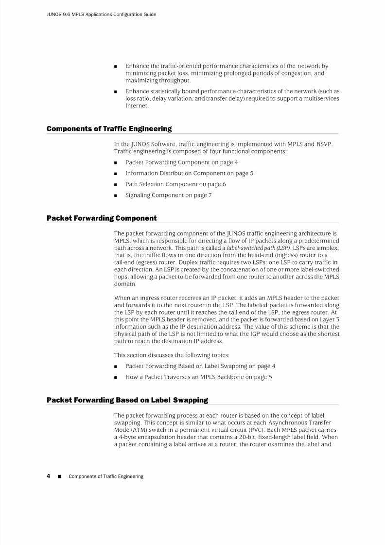
8/7/2019 Config Guide Mpls Applications
http://slidepdf.com/reader/full/config-guide-mpls-applications 42/547

8/7/2019 Config Guide Mpls Applications
http://slidepdf.com/reader/full/config-guide-mpls-applications 43/547
copies it as an index to its MPLS forwarding table. Each entry in the forwarding tablecontains an interface-inbound label pair mapped to a set of forwarding informationthat is applied to all packets arriving on the specific interface with the same inboundlabel.
How a Packet Traverses an MPLS Backbone
This section describes how an IP packet is processed as it traverses an MPLS backbonenetwork.
At the entry edge of the MPLS backbone, the IP header is examined by the ingressrouter. Based on this analysis, the packet is classified, assigned a label, encapsulatedin an MPLS header, and forwarded toward the next hop in the LSP. MPLS providesa high degree of flexibility in the way that an IP packet can be assigned to an LSP.For example, in the JUNOS traffic engineering implementation, all packets arrivingat the ingress router that are destined to exit the MPLS domain at the same egressrouter are forwarded along the same LSP.
Once the packet begins to traverse the LSP, each router uses the label to make theforwarding decision. The MPLS forwarding decision is made independently of theoriginal IP header: the incoming interface and label are used as lookup keys into theMPLS forwarding table. The old label is replaced with a new label, and the packet isforwarded to the next hop along the LSP. This process is repeated at each router inthe LSP until the packet reaches the egress router.
When the packet arrives at the egress router, the label is removed and the packetexits the MPLS domain. The packet is then forwarded based on the destination IPaddress contained in the packet’s original IP header according to the traditionalshortest path calculated by the IP routing protocol.
Information Distribution Component
Traffic engineering requires detailed knowledge about the network topology as wellas dynamic information about network loading. To implement the informationdistribution component, simple extensions to the IGPs are defined. Link attributesare included as part of each router’s link-state advertisement. IS-IS extensions includethe definition of new type length values (TLVs), whereas OSPF extensions areimplemented with opaque link-state advertisements (LSAs). The standard floodingalgorithm used by the link-state IGPs ensures that link attributes are distributed toall routers in the routing domain. Some of the traffic engineering extensions to beadded to the IGP link-state advertisement include maximum link bandwidth,maximum reserved link bandwidth, current bandwidth reservation, and link coloring.
Each router maintains network link attributes and topology information in aspecialized traffic engineering database. The traffic engineering database is usedexclusively for calculating explicit paths for the placement of LSPs across the physicaltopology. A separate database is maintained so that the subsequent traffic engineeringcomputation is independent of the IGP and the IGP’s link-state database. Meanwhile,the IGP continues its operation without modification, performing the traditionalshortest-path calculation based on information contained in the router’s link-statedatabase.
How a Packet Traverses an MPLS Backbone ■ 5
Chapter 1: Traffic Engineering Overview

8/7/2019 Config Guide Mpls Applications
http://slidepdf.com/reader/full/config-guide-mpls-applications 44/547

8/7/2019 Config Guide Mpls Applications
http://slidepdf.com/reader/full/config-guide-mpls-applications 45/547
An offline planning and analysis tool simultaneously examines each link’s resourceconstraints and the requirements of each LSP. Although the offline approach cantake several hours to complete, it performs global calculations, compares the resultsof each calculation, and then selects the best solution for the network as a whole.
The output of the offline calculation is a set of LSPs that optimizes utilization of network resources. After the offline calculation is completed, the LSPs can beestablished in any order because each is installed according to the rules for theglobally optimized solution.
Signaling Component
An LSP is not known to be workable until it is actually established by the signalingcomponent. The signaling component, which is responsible for establishing LSP stateand distributing labels, relies on a number of extensions to RSVP:
■ The Explicit Route object allows an RSVP path message to traverse an explicitsequence of routers that is independent of conventional shortest-path IP routing.
The explicit route can be either strict or loose.■ The Label Request object permits the RSVP path message to request that
intermediate routers provide a label binding for the LSP that it is establishing.
■ The Label object allows RSVP to support the distribution of labels without changingits existing mechanisms. Because the RSVP Resv message follows the reversepath of the RSVP path message, the Label object supports the distribution of labels from downstream nodes to upstream nodes.
Flexible LSP Calculation and Configuration
Traffic engineering involves mapping traffic flow onto a physical topology. You can
determine the paths online using constraint-based routing. Regardless of how thephysical path is calculated, the forwarding state is installed across the network throughRSVP.
The JUNOS Software supports the following ways to route and configure an LSP:
■ You can calculate the full path for the LSP offline and individually configure eachrouter in the LSP with the necessary static forwarding state. This is analogous tothe way some Internet service providers (ISPs) configure their IP-over-ATM cores.
■ You can calculate the full path for the LSP offline and statically configure theingress router with the full path. The ingress router then uses RSVP as a dynamicsignaling protocol to install a forwarding state in each router along the LSP.
■ You can rely on constraint-based routing to perform dynamic online LSPcalculation. You configure the constraints for each LSP; then the network itself determines the path that best meets those constraints. Specifically, the ingressrouter calculates the entire LSP based on the constraints and then initiatessignaling across the network.
■ You can calculate a partial path for an LSP offline and statically configure theingress router with a subset of the routers in the path; then you can permit onlinecalculation to determine the complete path.
Signaling Component ■ 7
Chapter 1: Traffic Engineering Overview

8/7/2019 Config Guide Mpls Applications
http://slidepdf.com/reader/full/config-guide-mpls-applications 46/547

8/7/2019 Config Guide Mpls Applications
http://slidepdf.com/reader/full/config-guide-mpls-applications 47/547
Chapter 2
Complete MPLS ApplicationsConfiguration Statements
This chapter is organized as follows:
■ [edit logical-systems] Hierarchy Level on page 9
■ [edit protocols connections] Hierarchy Level on page 10■ [edit protocols ldp] Hierarchy Level on page 10
■ [edit protocols link-management] Hierarchy Level on page 12
■ [edit protocols mpls] Hierarchy Level on page 13
■ [edit protocols rsvp] Hierarchy Level on page 17
[edit logical-systems] Hierarchy Level
The following MPLS protocol statements can be configured at the [edit logical-systems]hierarchy level. This is not a comprehensive list of statements available for logicalsystems. Only the statements that are also documented in this manual are listedhere. For more information about logical systems, see the JUNOS Routing ProtocolsConfiguration Guide.
NOTE: Beginning with JUNOS Software Release 9.3, the logical router feature hasbeen renamed logical system.
All configuration statements, operational commands, show command outputs, errormessages, log messages, and SNMP MIB objects that contain the string logical-routeror logical-routers have been changed to logical-system and logical-systems,respectively.
logical-systems {logical-system-name {
protocols {connections {
connections-configuration;}ldp {
ldp-configuration;}
[edit logical-systems] Hierarchy Level ■ 9

8/7/2019 Config Guide Mpls Applications
http://slidepdf.com/reader/full/config-guide-mpls-applications 48/547
link-management {link-management-configuration;
}mpls {
mpls-configuration;}rsvp {
rsvp-configuration;}
}}
}
[edit protocols connections] Hierarchy Level
The following statements can also be configured at the [edit logical-systemslogical-system-name] hierarchy level:
protocols {connections {
interface-switch connection-name {interface first-interface-name.unit-number ;interface second-interface-name.unit-number ;
}lsp-switch connection-name {
transmit-lsp label-switched-path;receive-lsp label-switched-path;
}p2mp-receive-switch {
output-interface interface-name.unit-number ;receive-p2mp-lsp receiving-point-to-multipoint-lsp;
}p2mp-transmit-switch {
input-interface input-interface-name.unit-number ;transmit-p2mp-lsp transmitting-point-to-multipoint-lsp;
}remote-interface-switch connection-name {
interface interface-name.unit-number ;transmit-lsp label-switched-path;receive-lsp label-switched-path;
}}
}
[edit protocols ldp] Hierarchy Level
The following statements can also be configured at the [edit logical-systemslogical-system-name] hierarchy level:
protocols {ldp {
(deaggregate | no-deaggregate);egress-policy [ policy-names ];explicit-null;
10 ■ [edit protocols connections] Hierarchy Level
JUNOS 9.6 MPLS Applications Configuration Guide

8/7/2019 Config Guide Mpls Applications
http://slidepdf.com/reader/full/config-guide-mpls-applications 49/547
export [ policy-names ];graceful-restart {
disable;helper-disable;
maximum-neighbor-recovery-time seconds;recovery-time seconds;}import [ policy-names];interface (interface-name | all) {
disable;hello-interval seconds;hold-time seconds;transport-address (interface | router-id);
}keepalive-interval seconds;keepalive-timeout seconds;log-updown {
trap disable;
}no-forwarding;oam {
bfd-liveness-detection {detection-time threshold milliseconds;ecmp;failure-action {
remove-nexthop;remove-route;
}holddown-interval milliseconds;minimum-interval milliseconds;minimum-receive-interval milliseconds;minimum-transmit-interval milliseconds;
multiplier detection-time-multiplier ;no-adaptation;transmit-interval {
minimum-interval milliseconds;threshold milliseconds;
}}fec fec-address;ingress-policy ingress-policy-name;periodic-traceroute {
disable;exp exp-value;fanout fanout-value;frequency minutes;
paths number-of-paths;retries retry-attempts;source address;ttl ttl-value;wait seconds;
}}policing {
fec fec-address {ingress-traffic filter-name;
[edit protocols ldp] Hierarchy Level ■ 11
Chapter 2: Complete MPLS Applications Configuration Statements

8/7/2019 Config Guide Mpls Applications
http://slidepdf.com/reader/full/config-guide-mpls-applications 50/547
transit-traffic filter-name;}
}preference preference;
session address {authentication-key md5-authentication-key ;}strict-targeted-hellos;traceoptions {
file filename <files number <size size> <world-readable | no-world-readable>;flag flag <flag-modifier > <disable>;
}track-igp-metric;traffic-statistics {
file filename <files number > <size size> <world-readable | no-world-readable>;interval interval;no-penultimate-hop;
}
transport-address (address | interface | router-id);}
}
[edit protocols link-management] Hierarchy Level
The following statements can also be configured at the [edit logical-systemslogical-system-name] hierarchy level:
protocols {link-management {
peer peer-name {address address;
control-channel [ control-channel-interfaces ];te-link [te-link-names];
}te-link te-link-name {
disable;interface interface-name {
disable;local-address address;remote-address address;remote-id id-number ;
}label-switched-path label-switched-path-name;local-address address;remote-address address;
remote-id id-number ;}traceoptions {
file filename <files number > <size size> <world-readable | no-world-readable>;flag flag <flag-modifier > <disable>;
}}
}
12 ■ [edit protocols link-management] Hierarchy Level
JUNOS 9.6 MPLS Applications Configuration Guide
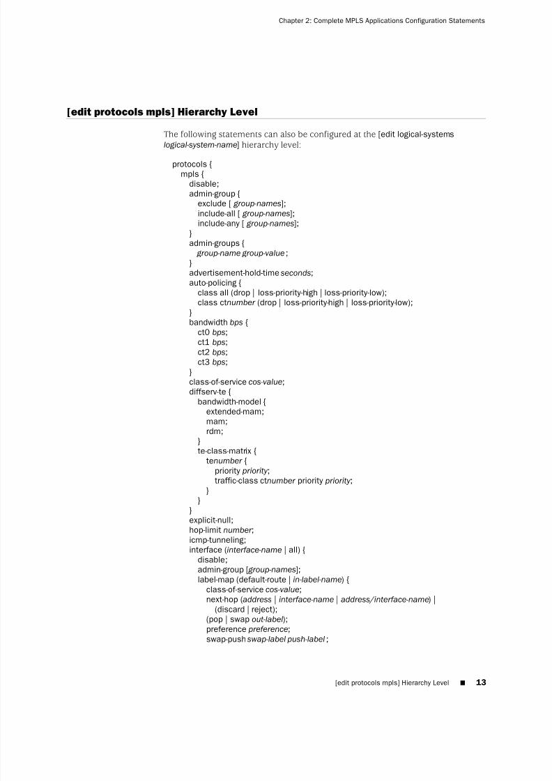
8/7/2019 Config Guide Mpls Applications
http://slidepdf.com/reader/full/config-guide-mpls-applications 51/547
[edit protocols mpls] Hierarchy Level
The following statements can also be configured at the [edit logical-systemslogical-system-name] hierarchy level:
protocols {mpls {
disable;admin-group {
exclude [ group-names];include-all [ group-names];include-any [ group-names];
}admin-groups {
group-name group-value;}
advertisement-hold-time seconds;auto-policing {
class all (drop | loss-priority-high | loss-priority-low);class ctnumber (drop | loss-priority-high | loss-priority-low);
}bandwidth bps {
ct0 bps;ct1 bps;ct2 bps;ct3 bps;
}class-of-service cos-value;diffserv-te {
bandwidth-model {
extended-mam;mam;rdm;
}te-class-matrix {
tenumber {priority priority ;traffic-class ctnumber priority priority ;
}}
}explicit-null;hop-limit number ;icmp-tunneling;
interface (interface-name | all) {disable;admin-group [ group-names];label-map (default-route | in-label-name) {
class-of-service cos-value;next-hop (address | interface-name | address/interface-name) |
(discard | reject);(pop | swap out-label);preference preference;swap-push swap-label push-label ;
[edit protocols mpls] Hierarchy Level ■ 13
Chapter 2: Complete MPLS Applications Configuration Statements

8/7/2019 Config Guide Mpls Applications
http://slidepdf.com/reader/full/config-guide-mpls-applications 52/547
}}ipv6-tunneling;label-switched-path lsp-name {
disable;adaptive;admin-down;admin-group {
exclude [ group-names ];include-all;include-any [ group-names ];
}auto-bandwidth {
adjust-interval seconds;adjust-threshold percent;maximum-bandwidth bps;minimum-bandwidth bps;monitor-bandwidth;
}bandwidth bps {
ct0 bps;ct1 bps;ct2 bps;ct3 bps;
}class-of-service cos-value;description text;fast-reroute {
(bandwidth bps | bandwidth-percent percent);(exclude [ group-names ] | no-exclude);hop-limit number ;(include-all [ group-names ] | no-include-all);
(include-any [ group-names ] | no-include-any);}from address;hop-limit number ;install {
destination-prefix /prefix-length <active>;}ldp-tunneling;link-protection;lsp-attributes {
encoding-type (ethernet | packet | pdh | sonet-sdh);gpid (ethernet | hdlc | ipv4 | ppp);signal-bandwidth type;switching-type (fiber | lambda | psc-1 | tdm);
}metric number ;no-cspf;no-decrement-ttl;node-link-protection;optimize-timer seconds;p2mp path-name;policing {
filter filter-name;no-automatic-policing;
14 ■ [edit protocols mpls] Hierarchy Level
JUNOS 9.6 MPLS Applications Configuration Guide

8/7/2019 Config Guide Mpls Applications
http://slidepdf.com/reader/full/config-guide-mpls-applications 53/547
}preference preference;primary path-name {
adaptive;
admin-group {exclude [ group-names ];include-all [ group-names ];include-any [ group-names ];
}bandwidth bps {
ct0 bps;ct1 bps;ct2 bps;ct3 bps;
}class-of-service cos-value;hop-limit number ;no-cspf;
no-decrement-ttl;optimize-timer seconds;preference preference;priority setup-priority reservation-priority ;(record | no-record);select (manual | unconditional);
}standby;
}priority setup-priority reservation-priority ;(random | least-fill | most-fill);(record | no-record);retry-limit number ;retry-timer seconds;
revert-timer seconds;secondary path-name {
adaptive;admin-group {
exclude [ group-names ];include-all [ group-names ];include-any [ group-names ];
}bandwidth bps {
ct0 bps;ct1 bps;ct2 bps;ct3 bps;
}class-of-service cos-value;hop-limit number ;no-cspf;no-decrement-ttl;optimize-timer seconds;preference preference;priority setup-priority reservation-priority ;(record | no-record);select (manual | unconditional);standby;
[edit protocols mpls] Hierarchy Level ■ 15
Chapter 2: Complete MPLS Applications Configuration Statements
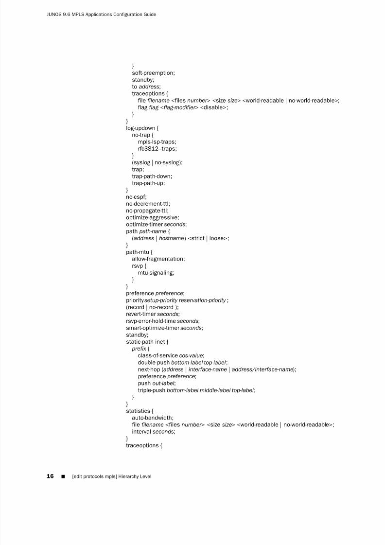
8/7/2019 Config Guide Mpls Applications
http://slidepdf.com/reader/full/config-guide-mpls-applications 54/547
}soft-preemption;standby;to address;
traceoptions {file filename <files number > <size size> <world-readable | no-world-readable>;flag flag <flag-modifier > <disable>;
}}log-updown {
no-trap {mpls-lsp-traps;rfc3812–traps;
}(syslog | no-syslog);trap;trap-path-down;trap-path-up;
}no-cspf;no-decrement-ttl;no-propagate-ttl;optimize-aggressive;optimize-timer seconds;path path-name {
(address | hostname) <strict | loose>;}path-mtu {
allow-fragmentation;rsvp {
mtu-signaling;}
}preference preference;priority setup-priority reservation-priority ;(record | no-record );revert-timer seconds;rsvp-error-hold-time seconds;smart-optimize-timer seconds;standby;static-path inet {
prefix {class-of-service cos-value;double-push bottom-label top-label;next-hop (address | interface-name | address/interface-name);preference preference;
push out-label;triple-push bottom-label middle-label top-label;
}}statistics {
auto-bandwidth;file filename <files number > <size size> <world-readable | no-world-readable>;interval seconds;
}traceoptions {
16 ■ [edit protocols mpls] Hierarchy Level
JUNOS 9.6 MPLS Applications Configuration Guide

8/7/2019 Config Guide Mpls Applications
http://slidepdf.com/reader/full/config-guide-mpls-applications 55/547
file filename <files number > <size size> <world-readable | no-world-readable>;flag flag ;
}traffic-engineering (bgp | bgp-igp | bgp-igp-both-ribs | mpls-forwarding);
}
[edit protocols rsvp] Hierarchy Level
The following statements can also be configured at the [edit logical-systemslogical-system-name] hierarchy level:
protocols {rsvp {
disable;fast-reroute optimize-timer seconds;graceful-deletion-timeout seconds;graceful-restart {
disable;helper-disable;maximum-helper-recovery-time seconds;maximum-helper-restart-time seconds;
}interface interface-name {
disable;(aggregate | no-aggregate);authentication-key key ;bandwidth bps;hello-interval seconds;link-protection {
disable;admin-group {
exclude group-names;include-all group-names;include-any group-names;
}bandwidth bandwidth;bypass bypass-name {
bandwidth bps {ct0 bps;ct1 bps;ct2 bps;ct3 bps;
}hop-limit number ;no-cspf;path address <strict | loose>;priority setup-priority reservation-priority ;to address;
}class-of-service cos-value;hop-limit number ;max-bypasses number ;no-cspf;no-node-protection;
[edit protocols rsvp] Hierarchy Level ■ 17
Chapter 2: Complete MPLS Applications Configuration Statements

8/7/2019 Config Guide Mpls Applications
http://slidepdf.com/reader/full/config-guide-mpls-applications 56/547
optimize-timer seconds;path address <strict | loose>;priority setup-priority reservation-priority ;subscription percentage {
ct0 percentage;ct1 percentage;ct2 percentage;ct3 percentage;
}}(reliable | no-reliable);subscription percentage {
ct0 percentage;ct1 percentage;ct2 percentage;ct3 percentage;
}update-threshold percentage;
}keep-multiplier number ;load-balance {
bandwidth;}no-node-id-subobject;no-p2mp-sublsp;peer-interface peer-interface-name {
(aggregate | no-aggregate);authentication-key key ;disable;hello-interval seconds;(reliable | no-reliable);
}
preemption {(aggressive | disabled | normal);soft-preemption {
cleanup-timer seconds;}
}refresh-time seconds;traceoptions {
file filename <files number > <size size> <world-readable | no-world-readable>;flag flag <flag-modifier > <disable>;
}tunnel-services {
devices device-names;}
}}
18 ■ [edit protocols rsvp] Hierarchy Level
JUNOS 9.6 MPLS Applications Configuration Guide

8/7/2019 Config Guide Mpls Applications
http://slidepdf.com/reader/full/config-guide-mpls-applications 57/547
Part 2
MPLS
■ MPLS Overview on page 21
■ MPLS Router Configuration Guidelines on page 51
■ MPLS-Signaled LSP Configuration Guidelines on page 69
■ DiffServ-Aware Traffic Engineering Configuration Guidelines on page 109
■
Static and Explicit-Path LSP Configuration Guidelines on page 133■ Point-to-Multipoint LSP Configuration Guidelines on page 141
■ Miscellaneous MPLS Properties Configuration Guidelines on page 149
■ Summary of MPLS Configuration Statements on page 173
MPLS ■ 19

8/7/2019 Config Guide Mpls Applications
http://slidepdf.com/reader/full/config-guide-mpls-applications 58/547
20 ■ MPLS
JUNOS 9.6 MPLS Applications Configuration Guide

8/7/2019 Config Guide Mpls Applications
http://slidepdf.com/reader/full/config-guide-mpls-applications 59/547
Chapter 3
MPLS Overview
This chapter discusses the following topics:
■ MPLS Introduction on page 22
■ MPLS Standards on page 22
■ Link-Layer Support on page 24
■ MPLS and Traffic Engineering on page 24
■ Label Description on page 25
■ Special Labels on page 25
■ Label Allocation on page 26
■ Operations on Labels on page 27
■ Routers in an LSP on page 28
■ How a Packet Travels Along an LSP on page 28
■ Types of LSPs on page 29
■ Scope of LSPs on page 29
■ Constrained-Path LSP Computation on page 29
■ How CSPF Selects a Path on page 31
■ Path Selection Tie-Breaking on page 32
■ Computing Paths Offline on page 32
■ LSPs on an Overloaded Router on page 33
■ Fate Sharing on page 33
■ IGP Shortcuts on page 34
■ Enabling IGP Shortcuts on page 35
■ LSPs Qualified in Shortcut Computations on page 36
■ IGP Shortcut Applications on page 36■ IGP Shortcuts and Routing Table on page 37
■ IGP Shortcuts and VPN Environments on page 37
■ Advertising LSPs into IGPs on page 37
■ IP and MPLS Packets on Aggregated Interfaces on page 38
■ MPLS Applications on page 39
■ BGP Destinations on page 39
■ 21

8/7/2019 Config Guide Mpls Applications
http://slidepdf.com/reader/full/config-guide-mpls-applications 60/547
■ IGP and BGP Destinations on page 41
■ Selecting a Forwarding LSP Next Hop on page 41
■ MPLS and Routing Tables on page 41
■ MPLS and Traffic Protection on page 43
■ Fast Reroute on page 44
■ Fast Reroute Overview on page 44
■ Detour Merging Process on page 46
■ Detour Computations on page 47
■ Fast Reroute Path Optimization on page 47
■ Automatic Bandwidth Allocation on page 48
■ Point-to-Multipoint LSPs on page 48
■ MPLS Load Balancing Based on the IP Header and MPLS Labels on page 50
MPLS Introduction
MPLS provides a mechanism for engineering network traffic patterns that isindependent of routing tables. MPLS assigns short labels to network packets thatdescribe how to forward them through the network. MPLS is independent of anyrouting protocol and can be used for unicast packets.
In the traditional Level 3 forwarding paradigm, as a packet travels from one routerto the next, an independent forwarding decision is made at each hop. The IP networklayer header is analyzed, and the next hop is chosen based on this analysis and onthe information in the routing table. In an MPLS environment, the analysis of thepacket header is performed just once, when a packet enters the MPLS cloud. The
packet is then assigned to a stream, which is identified by a label, which is a short(20-bit), fixed-length value at the front of the packet. Labels are used as lookup indexesfor the label forwarding table. For each label, this table stores forwarding information.You can associate additional information with a label—such as class-of-service (CoS)values—that can be used to prioritize packet forwarding.
MPLS Standards
The JUNOS Software supports the following RFCs and Internet drafts related to MPLS:
■ RFC 2702, Requirements for Traffic Engineering Over MPLS
■ RFC 2858, Multiprotocol Extensions for BGP-4
■ RFC 3063, MPLS Loop Prevention Mechanism
■ RFC 3031, Multiprotocol Label Switching Architecture (provides a good overviewof MPLS)
■ RFC 3032, MPLS Label Stack Encoding
■ RFC 3140, Per Hop Behavior Identification Codes
■ RFC 3208, PGM Reliable Transport Protocol Specification (only the networkelement)
22 ■ MPLS Introduction
JUNOS 9.6 MPLS Applications Configuration Guide

8/7/2019 Config Guide Mpls Applications
http://slidepdf.com/reader/full/config-guide-mpls-applications 61/547
■ RFC 3270, Multi-Protocol Label Switching (MPLS) Support of Differentiated Services(E-LSPs only)
■ RFC 3443, Time To Live (TTL) Processing in Multi-Protocol Label Switching (MPLS)Networks
■ RFC 3469, Framework for Multi-Protocol Label Switching (MPLS)-based Recovery
■ RFC 3478, Graceful Restart Mechanism for LDP
■ RFC 3564, Requirements for Support of Differentiated Services-aware MPLS Traffic Engineering
■ RFC 4124, Protocol Extensions for Support of Differentiated-Service-aware MPLS Traffic Engineering
■ RFC 4125, Maximum Allocation Bandwidth Constraints Model for Diff-Serv-awareMPLS Traffic Engineering
■ RFC 4127, Russian Dolls Bandwidth Constraints Model for Diff-Serv-aware MPLS Traffic Engineering
■ RFC 4364, BGP/MPLS IP Virtual Private Networks (VPNs)
■ RFC 4379, Detecting Multi-Protocol Label Switched (MPLS) Data Plane Failures.
■ RFC 4950, ICMP Extensions for Multiprotocol Label Switching
■ Internet draft draft-ietf-bfd-mpls-02.txt, BFD for MPLS LSPs
■ Internet draft draft-ietf-mpls-rsvp-lsp-fastreroute-03.txt, Fast Reroute Extensionsto RSVP-TE for LSP Tunnels (except node protection in facility backup)
■ Internet draft draft-ietf-mpls-label-encaps-07.txt, MPLS Label Stack Encoding
■ Internet draft draft-ietf-mpls-p2mp-requirement-02.txt, Requirements for Point to Multipoint Extensions to RSVP-TE (no expiration; revised January 2004)
■ Internet draft draft-ietf-mpls-soft-preemption-02.txt, MPLS Traffic EngineeringSoft Preemption (no expiration; revised March 2004)
■ Internet draft draft-ietf-ppvpn-rfc2547bis-03.txt, BGP/MPLS VPNs
■ Internet draft draft-martini-l2circuit-encap-mpls-07.txt, Encapsulation Methods for Transport of Layer 2 Frames Over IP and MPLS Networks
The JUNOS Software has the following exceptions:
■ A packet with a sequence number of 0 is treated as out of sequence.
■ Any packet which does not have the next incremental sequence number isconsidered out of sequence.
■ When out-of-sequence packets arrive, the expected sequence number for theneighbor is set to the sequence number in the Layer 2 circuit control word.
■ Internet draft draft-martini-l2circuit-trans-mpls-14.txt, Transport of Layer 2 FramesOver MPLS
■ Internet draft draft-raggarwa-mpls-p2mp-te-02.txt (except non-adjacent signalingfor branch LSPs, make-before-break and fast reroute, and LSP hierarchy usingP2P LSPs), Establishing Point to Multipoint MPLS TE LSPs (no expiration; revised
January 2004)
MPLS Standards ■ 23
Chapter 3: MPLS Overview

8/7/2019 Config Guide Mpls Applications
http://slidepdf.com/reader/full/config-guide-mpls-applications 62/547
The following documents provide information about traffic engineering:
■ RFC 2702, Requirements for Traffic Engineering Over MPLS
■ RFC 4090, Fast Reroute Extensions to RSVP-TE for LSP Tunnels
■ Internet draft draft-ietf-isis-traffic-04.txt, IS-IS Extensions for Traffic Engineering(expires February 2002)
■ Internet draft draft-katz-yeung-ospf-traffic-06.txt, Traffic Engineering Extensionsto OSPF (expires April 2002)
■ Internet draft draft-ietf-mpls-rsvp-te-p2mp-01.txt, Extensions to RSVP-TE for Point to Multipoint TE LSPs (expires June 2005)
To access Internet RFCs and drafts, go to the IETF website at http://www.ietf.org.
The JUNOS Software supports a proprietary MIB for MPLS objects; see the JUNOS Network Management Configuration Guide for more information.
Link-Layer Support
MPLS supports the following link-layer protocols, which are all supported in the JUNOS MPLS implementation:
■ Point-to-Point Protocol (PPP)—Protocol ID 0x0281, Network Control Protocol(NCP) protocol ID 0x8281.
■ Ethernet/Cisco High-level Data Link Control (HDLC)—Ethernet type 0x8847.
■ Asynchronous Transfer Mode (ATM)—Subnetwork attachment point encoded(SNAP-encoded) Ethernet type 0x8847. Support is included for both point-to-pointmode or nonbroadcast multiaccess (NBMA) mode. Support is not included for
encoding MPLS labels as part of ATM virtual path identifier/virtual circuit identifier(VPI/VCI).
■ Frame Relay—SNAP-encoded, Ethernet type 0x8847. Support is not includedfor encoding MPLS labels as part of Frame Relay data-link connection identifier(DLCI).
■ Generic routing encapsulation (GRE) tunnel—Ethernet type 0x8847.
MPLS and Traffic Engineering
Traffic engineering allows you to control the path that data packets follow, bypassingthe standard routing model, which uses routing tables. Traffic engineering moves
flows from congested links to alternate links that would not be selected by theautomatically computed destination-based shortest path. With traffic engineering,you can:
■ Make more efficient use of expensive long-haul fibers.
■ Control how traffic is rerouted in the face of single or multiple failures.
■ Classify critical and regular traffic on a per-path basis.
24 ■ Link-Layer Support
JUNOS 9.6 MPLS Applications Configuration Guide
8/7/2019 Config Guide Mpls Applications
http://slidepdf.com/reader/full/config-guide-mpls-applications 63/547

8/7/2019 Config Guide Mpls Applications
http://slidepdf.com/reader/full/config-guide-mpls-applications 64/547
■ 0, IPv4 Explicit Null label—This value is legal only when it is the sole label entry(no label stacking). It indicates that the label must be popped upon receipt.Forwarding continues based on the IP version 4 (IPv4) packet.
■ 1, Router Alert label—When a packet is received with a top label value of 1, itis delivered to the local software module for processing.
■ 2, IPv6 Explicit Null label—This value is legal only when it is the sole label entry(no label stacking). It indicates that the label must be popped on receipt.Forwarding continues based on the IP version 6 (IPv6) packet.
■ 3, Implicit Null label—This label is used in the control protocol (LDP or RSVP)only to request label popping by the downstream router. It never actually appearsin the encapsulation. Labels with a value of 3 should not be used in the datapacket as real labels. No payload type (IPv4 or IPv6) is implied with this label.
■ 4 through 15—Unassigned.
Special labels are commonly used between the egress and penultimate routers of an
LSP. If the LSP is configured to carry IPv4 packets only, the egress router might signalthe penultimate router to use 0 as a final-hop label. If the LSP is configured to carryIPv6 packets only, the egress router might signal the penultimate router to use 2 asa final-hop label.
The egress router might simply signal the penultimate router to use 3 as the finallabel, which is a request to perform penultimate-hop label popping. The egress routerwill not process a labeled packet; rather, it receives the payload (IPv4, IPv6, or others)directly, reducing one MPLS lookup at egress.
For label-stacked packets, the egress router receives an MPLS label packet with itstop label already popped by the penultimate router. The egress router cannot receivelabel-stacked packets that use label 0 or 2. It typically requests label 3 from the
penultimate router.
Label Allocation
In the JUNOS Software, label values are allocated per router. The display output showsonly the label (for example, 01024). Labels for multicast packets are independent of those for unicast packets. Currently, the JUNOS Software does not support multicastlabels.
Labels are assigned by downstream routers relative to the flow of packets. A routerreceiving labeled packets (the next-hop router) is responsible for assigning incominglabels. A received packet containing a label that is unrecognized (unassigned) isdropped. For unrecognized labels, the router does not attempt to unwrap the labelto analyze the network layer header, nor does it generate an Internet Control MessageProtocol (ICMP) destination unreachable message.
A packet can carry a number of labels, organized as a last-in, first-out stack. This isreferred to as a label stack. At a particular router, the decision about how to forwarda labeled packet is based exclusively on the label at the top of the stack.
Figure 1 on page 27 shows the encoding of a single label. The encoding appears afterdata link layer headers, but before any network layer header.
26 ■ Label Allocation
JUNOS 9.6 MPLS Applications Configuration Guide
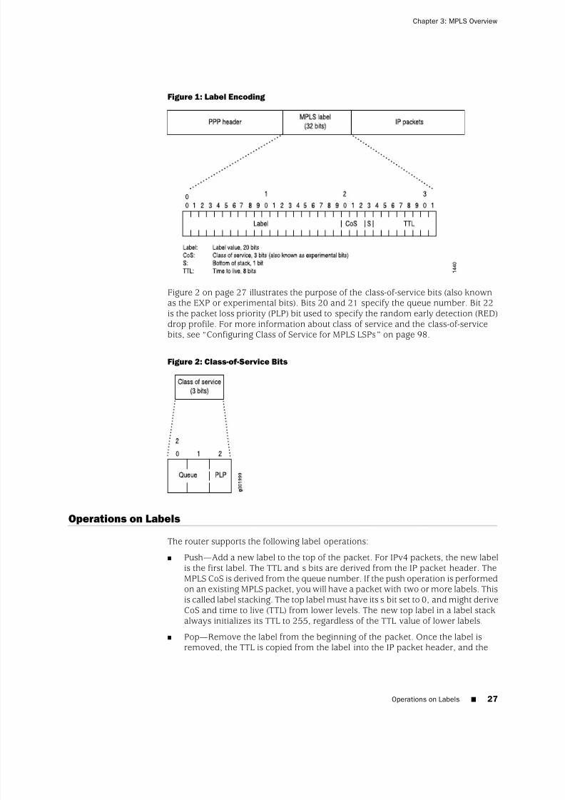
8/7/2019 Config Guide Mpls Applications
http://slidepdf.com/reader/full/config-guide-mpls-applications 65/547
Figure 1: Label Encoding
Figure 2 on page 27 illustrates the purpose of the class-of-service bits (also knownas the EXP or experimental bits). Bits 20 and 21 specify the queue number. Bit 22is the packet loss priority (PLP) bit used to specify the random early detection (RED)drop profile. For more information about class of service and the class-of-servicebits, see “Configuring Class of Service for MPLS LSPs” on page 98.
Figure 2: Class-of-Service Bits
Operations on Labels
The router supports the following label operations:
■
Push—
Add a new label to the top of the packet. For IPv4 packets, the new labelis the first label. The TTL and s bits are derived from the IP packet header. TheMPLS CoS is derived from the queue number. If the push operation is performedon an existing MPLS packet, you will have a packet with two or more labels. Thisis called label stacking. The top label must have its s bit set to 0, and might deriveCoS and time to live (TTL) from lower levels. The new top label in a label stackalways initializes its TTL to 255, regardless of the TTL value of lower labels.
■ Pop—Remove the label from the beginning of the packet. Once the label isremoved, the TTL is copied from the label into the IP packet header, and the
Operations on Labels ■ 27
Chapter 3: MPLS Overview

8/7/2019 Config Guide Mpls Applications
http://slidepdf.com/reader/full/config-guide-mpls-applications 66/547

8/7/2019 Config Guide Mpls Applications
http://slidepdf.com/reader/full/config-guide-mpls-applications 67/547
When the packet reaches the egress router, the label is removed, and the packetagain becomes a native IP packet and is again forwarded based on its IProuting information.
Types of LSPs
There are three types of LSPs:
■ Static LSPs—For static paths, you must manually assign labels on all routersinvolved (ingress, transit, and egress). No signaling protocol is needed. Thisprocedure is similar to configuring static routes on individual routers. Like staticroutes, there is no error reporting, liveliness detection, or statistics reporting.
■ LDP-signaled LSPs—See “LDP Overview” on page 329.
■ RSVP-signaled LSPs—For signaled paths, RSVP is used to set up the path anddynamically assign labels. (RSVP signaling messages are used to set up signaledpaths.) You configure only the ingress router. The transit and egress routers
accept signaling information from the ingress router, and they set up and maintainthe LSP cooperatively. Any errors encountered while establishing an LSP arereported to the ingress router for diagnostics. For signaled LSPs to work, a versionof RSVP that supports tunnel extensions must be enabled on all routers.
There are two types of RSVP-signaled LSPs:
■ Explicit-path LSPs—All intermediate hops of the LSP are manually configured.The intermediate hops can be strict, loose, or any combination of the two. Explicitpath LSPs provide you with complete control over how the path is set up. Theyare similar to static LSPs but require much less configuration.
■ Constrained-path LSPs—The intermediate hops of the LSP are automaticallycomputed by the software. The computation takes into account information
provided by the topology information from the IS-IS or OSPF link-state routingprotocol, the current network resource utilization determined by RSVP, and theresource requirements and constraints of the LSP. For signaled constrained-pathLSPs to work, either the IS-IS or OSPF protocol and the IS-IS or OSPF trafficengineering extensions must be enabled on all routers.
Scope of LSPs
For constrained-path LSPs, the LSP computation is confined to one IGP domain, andcannot cross any AS boundary. This prevents an AS from extending its IGP intoanother AS.
Explicit-path LSPs, however, can cross as many AS boundaries as necessary. Becauseintermediate hops are manually specified, the LSP does not depend on the IGPtopology or a local forwarding table.
Constrained-Path LSP Computation
The Constrained Shortest Path First (CSPF) algorithm is an advanced form of theshortest-path-first (SPF) algorithm used in OSPF and IS-IS route computations. CSPF
Types of LSPs ■ 29
Chapter 3: MPLS Overview

8/7/2019 Config Guide Mpls Applications
http://slidepdf.com/reader/full/config-guide-mpls-applications 68/547
is used in computing paths for LSPs that are subject to multiple constraints. Whencomputing paths for LSPs, CSPF considers not only the topology of the network, butalso the attributes of the LSP and the links, and it attempts to minimize congestionby intelligently balancing the network load.
The constraints that CSPF considers include:
■ LSP attributes
■ Administrative groups (that is, link color requirements)
■ Bandwidth requirements
■ Explicit route (strict or loose)
■ Hop limitations
■ Priority (setup and hold)
■ Link attributes
■ Administrative groups (that is, link colors assigned to the link)
■ Reservable bandwidth of the links (static bandwidth minus the currentlyreserved bandwidth)
The data that CSPF considers comes from the following sources:
■ Traffic engineering database—Provides CSPF with up-to-date topologyinformation, the current reservable bandwidth of links, and the link colors. Forthe CSPF algorithm to perform its computations, a link-state IGP (such as OSPFor IS-IS) with special extensions is needed. For CSPF to be effective, the link-stateIGP on all routers must support the special extensions. While building the topologydatabase, the extended IGP must take into consideration the current LSPs andmust flood the route information everywhere. Because changes in the reservedlink bandwidth and link color cause database updates, an extended IGP tendsto flood more frequently than a normal IGP. See Figure 3 on page 31 for adiagram of the relationships between these components.
■ Currently active LSPs—Includes all the LSPs that should originate from the routerand their current operational status (up, down, or timeout).
30 ■ Constrained-Path LSP Computation
JUNOS 9.6 MPLS Applications Configuration Guide

8/7/2019 Config Guide Mpls Applications
http://slidepdf.com/reader/full/config-guide-mpls-applications 69/547
Figure 3: CSPF Computation Process
This section discusses the following topics:■ How CSPF Selects a Path on page 31
■ Path Selection Tie-Breaking on page 32
■ Computing Paths Offline on page 32
How CSPF Selects a Path
To select a path, CSPF follows these steps:
1. Computes LSPs one at a time, beginning with the highest priority LSP (the onewith the lowest setup priority value). Among LSPs of equal priority, CSPF starts
with those that have the highest bandwidth requirement.2. Prunes the traffic engineering database of all the links that are not full duplex
and do not have sufficient reservable bandwidth.
3. If the LSP configuration includes the include statement, prunes all links that donot share any included colors.
4. If the LSP configuration includes the exclude statement, prunes all links thatcontain excluded colors. If the link does not have a color, it is accepted.
5. Finds the shortest path toward the LSP’s egress router, taking into accountexplicit-path constraints. For example, if the path must pass through Router A,two separate SPFs are computed, one from the ingress router to Router A, theother from Router A to the egress router.
6. If several paths have equal cost, chooses the one whose last-hop address is thesame as the LSP’s destination.
7. If several equal-cost paths remain, selects the one with the fewest number of hops.
8. If several equal-cost paths remain, applies the CSPF load-balancing rule configuredon the LSP (least fill, most fill, or random).
How CSPF Selects a Path ■ 31
Chapter 3: MPLS Overview
8/7/2019 Config Guide Mpls Applications
http://slidepdf.com/reader/full/config-guide-mpls-applications 70/547
Path Selection Tie-Breaking
If more than one path is available after the rules from the previous section have beenapplied, a tie-breaking rule is applied to choose the path for the LSP. There are threetie-breaking rules:
■ Random—One of the remaining paths is picked at random. This rule tends toplace an equal number of LSPs on each link, regardless of the available bandwidthratio.
■ Least fill—The path with the largest minimum available bandwidth ratio ispreferred. This rule tries to equalize the reservation on each link.
■ Most fill—The path with the smallest minimum available bandwidth ratio ispreferred. This rule tries to fill a link before moving on to alternative links.
The rule used depends on the configuration. Random is the default rule.
For the other rules, the following definitions are needed:
■ Reservable bandwidth = bandwidth of link x subscription factor of link
■ Available bandwidth = reservable bandwidth – (sum of the bandwidths of theLSPs traversing the link)
■ Available bandwidth ratio = available bandwidth/reservable bandwidth
■ Minimum available bandwidth ratio (for a path) = the smallest availablebandwidth ratio of the links in a path
Computing Paths Offline
The JUNOS Software provides online, real-time CSPF computation only; each routerperforms CSPF calculations independent of the other routers in the network. Thesecalculations are based on currently available topology information—information thatis usually recent, but not completely accurate. LSP placements are locally optimized,based on current network status.
To optimize links globally across the network, you can use an offline tool to performthe CSPF calculations and determine the paths for the LSPs. You can create such atool yourself, or you can modify an existing network design tool to perform thesecalculations. You should run the tool periodically (daily or weekly) and download theresults into the router. An offline tool should take the following into account whenperforming the optimized calculations:
■ All the LSP’s requirements
■ All link attributes
■ Complete network topology
32 ■ Path Selection Tie-Breaking
JUNOS 9.6 MPLS Applications Configuration Guide

8/7/2019 Config Guide Mpls Applications
http://slidepdf.com/reader/full/config-guide-mpls-applications 71/547
LSPs on an Overloaded Router
An overloaded router is a router running IS-IS with its overload bit set in its IS-ISconfiguration. In this case, an MPLS LSP specifically refers to an RSVP-signaled orLDP-signaled LSP. In the case of RSVP, it applies to both CSPF and non-CSPF LSPs.
You cannot establish transit LSPs through an overloaded router. However, you canconfigure ingress and egress LSPs through an overloaded router.
NOTE: When you set the overload bit on an IS-IS router, all LSPs transiting throughit are recomputed and rerouted away from it. If the recomputation fails, no additionalattempt to reconfigure the LSP is made, and the affected LSPs are disconnected.
An example of when you might want to establish transit LSPs through an overloadedrouter is illustrated in Figure 4 on page 33, which shows an aggregation router (RouterA) dual-homed on two core routers (Router B and Router C). You want to include theaggregation router in the LSP mesh, but transit LSPs should not pass through it,because it is a less capable router with relatively low-bandwidth uplinks to the core.Certain failure and rerouting scenarios could make it impossible for the aggregationrouter to establish some of its LSPs. Consequently, you run the router in a steadystate with the overload bit set, but you are still able to establish ingress and egressLSPs through it.
Figure 4: Aggregation Router A Dual-Homed on Core Routers B and C
Fate Sharing
Fate sharing allows you to create a database of information that CSPF uses to computeone or more backup paths to use in case the primary path becomes unstable. Thedatabase describes the relationships between elements of the network, such asrouters and links. You can specify one or more elements within a group.
Through fate sharing, you can configure backup paths that minimize the number of shared links and fiber paths with the primary paths as much as possible, to ensure
LSPs on an Overloaded Router ■ 33
Chapter 3: MPLS Overview

8/7/2019 Config Guide Mpls Applications
http://slidepdf.com/reader/full/config-guide-mpls-applications 72/547
that if a fiber is cut, the minimum amount of data is lost and a path still exists to thedestination.
For a backup path to work optimally, it must not share links or physical fiber paths
with the primary path, ensuring that a single point of failure will not affect the primaryand backup paths simultaneously. For more information about fate sharing, see the JUNOS Routing Protocols Configuration Guide.
IGP Shortcuts
Link-state protocols, such as OSPF and IS-IS, use the SPF algorithm to compute theshortest-path tree to all nodes in the network. The results of such computations canbe represented by the destination node, next-hop address, and output interface,where the output interface is a physical interface. LSPs can be used to augment theSPF algorithm, for the purposes of resolving BGP next hops. On the node performingthe calculations, LSPs appear to be logical interfaces directly connected to remotenodes in the network. If you configure the IGP to treat LSPs the same as a physicalinterface and use the LSPs as a potential output interface, the SPF computation resultsare represented by the destination node and output LSP, effectively using the LSPas a shortcut through the network to the destination.
As an illustration, begin with a typical SPF tree (see Figure 5 on page 34).
Figure 5: Typical SPF Tree, Sourced from Router A
If an LSP connects Router A to Router D and if IGP shortcuts are enabled on Router A,you might have the SPF tree shown in Figure 6 on page 34.
Figure 6: Modified SPF Tree, Using LSP A–D as a Shortcut
Note that Router D is now reachable through LSP A–D. When computing the shortestpath to reach Router D, Router A has two choices:
34 ■ IGP Shortcuts
JUNOS 9.6 MPLS Applications Configuration Guide

8/7/2019 Config Guide Mpls Applications
http://slidepdf.com/reader/full/config-guide-mpls-applications 73/547
■ Use IGP path A–B–D.
■ Use LSP A–D.
Router A decides between the two choices by comparing the IGP metrics for pathA–B–D with the LSP metrics for LSP A–D. If the IGP metric is lower, path A–B–D ischosen (Figure 5 on page 34). If the LSP metric is lower, LSP A–D is used (Figure 6on page 34). If both metrics are equal, LSP A–D is chosen because LSP paths arepreferred over IGP paths.
Note that Routers E and F are also reachable through LSP A–D, because they aredownstream from Router D in the SPF tree.
Assuming that another LSP connects Router A to Router E, you might have the SPFtree shown in Figure 7 on page 35.
Figure 7: Modified SPF Tree, Using LSP A–D and LSP A–E as Shortcuts
This section discusses the following topics:
■ Enabling IGP Shortcuts on page 35
■ LSPs Qualified in Shortcut Computations on page 36
■ IGP Shortcut Applications on page 36
■ IGP Shortcuts and Routing Table on page 37
■ IGP Shortcuts and VPN Environments on page 37
Enabling IGP Shortcuts
IGP shortcuts are supported for both IS-IS and OSPF. A link-state protocol is requiredfor IGP shortcuts. Shortcuts are disabled by default. For information about enablingIGP shortcuts for IS-IS and OSPF, see the JUNOS Routing Protocols Configuration Guide.
You can enable IGP shortcuts on a per-router basis; you do not need to enableshortcuts globally. A router’s shortcut computation does not depend on anotherrouter performing similar computations, and shortcuts performed by other routersare irrelevant.
Enabling IGP Shortcuts ■ 35
Chapter 3: MPLS Overview

8/7/2019 Config Guide Mpls Applications
http://slidepdf.com/reader/full/config-guide-mpls-applications 74/547

8/7/2019 Config Guide Mpls Applications
http://slidepdf.com/reader/full/config-guide-mpls-applications 75/547
When intraregion LSPs are in place, interregional traffic automatically traverses theintraregion LSPs as needed, eliminating the need for a full mesh of LSPs betweenedge routers. For example, traffic from Router A to Router D traverses LSPs A–B,B–C, and C–D.
IGP Shortcuts and Routing Table
IGP typically performs two independent computations. The first is performed withoutconsidering any LSP. The result of the computation is stored in the inet.0 table. Thisstep is no different from traditional SPF computations and is always performed evenif IGP shortcut is disabled.
The second computation is performed considering only LSPs as a logical interface.Each LSP’s egress router is considered. The list of destinations whose shortest pathtraverses the egress router (established during the first computation) is placed in theinet.3 routing table. These destinations are given the egress router of the LSP as anext hop, enabling BGP on the local router to use these LSPs to access BGP next hopsbeyond the egress router. Normally, BGP can use only LSPs that terminate at theBGP next hop. Note that BGP is the only protocol that uses the inet.3 routing table.Other protocols will not route traffic through these LSPs.
If traffic engineering for IGP and BGP is enabled (see “IGP and BGP Destinations” onpage 41), IGP moves all routes in inet.3 into inet.0, merging all routes while emptyingthe inet.3 table. The number of routes in inet.0 will be exactly the same as before.Route next-hops can traverse a physical interface, an LSP, or the combination of thetwo if the metrics are equal.
IGP shortcuts are enabled on a per-node basis. You do not need to coordinate withother nodes.
IGP Shortcuts and VPN Environments
IGP shortcuts (configured under the [edit protocols mpls traffic-engineering bgp-igp]hierarchy level and under the [edit protocols ospf traffic-engineering shortcuts] hierarchylevel) do not work in VPN environments. IGP shortcuts move routes in the inet.3routing table to the inet.0 routing table. Virtual private network (VPN) IBGP (whichbelongs to family inet-vpn) relies on next hops that are in the inet.3 table, so IGPshortcuts are incompatible with VPNs.
Advertising LSPs into IGPs
You can configure your IGP to treat an LSP as a link. IGP shortcuts allow only theingress router of an LSP to use the LSP in its SPF computation. However, other routerson the network do not know of the existence of that LSP, so they cannot use it. Thiscan lead to suboptimal traffic engineering. In addition, only BGP can use an IGPshortcut to an LSP. When you advertise an LSP as a link into the IGP, all traffic cantraverse it, and all routers know about it.
As an example, consider the network shown in Figure 10 on page 38.
IGP Shortcuts and Routing Table ■ 37
Chapter 3: MPLS Overview
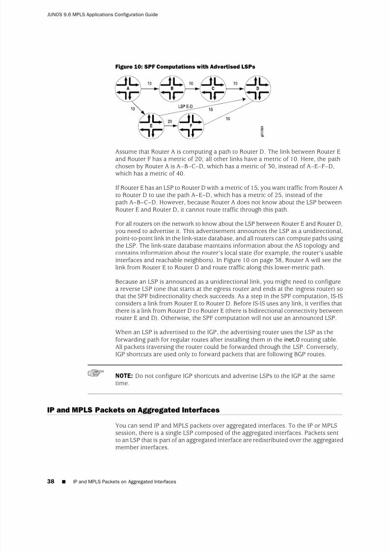
8/7/2019 Config Guide Mpls Applications
http://slidepdf.com/reader/full/config-guide-mpls-applications 76/547

8/7/2019 Config Guide Mpls Applications
http://slidepdf.com/reader/full/config-guide-mpls-applications 77/547
Sending IP and MPLS packets over aggregated interfaces has the following benefits:
■ Bandwidth aggregation—You can increase the number of MPLS packet flowssent over each connection. In MPLS, a set of packets sharing the same label isconsidered a part of the same flow.
■ Link redundancy—If a link or a line card failure affects an aggregate memberlink, the traffic flowing across that link is immediately forwarded across one of the remaining links.
JUNOS supports aggregated SONET and Ethernet interfaces.
Note that the JUNOS implementation of IP and MPLS over aggregated interfaces(aggregated Ethernet devices only) complies with IEEE 802.3ad.
For information about how to configure aggregated Ethernet or aggregated SONETinterfaces, see the JUNOS Network Interfaces Configuration Guide .
MPLS Applications
In the JUNOS Software implementation of MPLS, establishing an LSP installs on theingress router a host route (a 32-bit mask) toward the egress router. The address of the host route is the destination address of the LSP. By default, the route has apreference value of 7, a value that is higher than all routes except direct interfaceand static routes. The 32-bit mask ensures that the route is more specific (that is, alonger match) than all other subnet routes. The host routes can be used totraffic-engineer BGP destinations only, or both IGP and BGP destinations.
This section discusses the following topics:
■ BGP Destinations on page 39
■ IGP and BGP Destinations on page 41
■ Selecting a Forwarding LSP Next Hop on page 41
BGP Destinations
You can configure MPLS to control the paths that traffic takes to destinations outsidean AS.
Both IBGP and EBGP take advantage of the LSP host routes without requiring extraconfiguration. BGP compares the BGP next-hop address with the LSP host route. If a match is found, the packets for the BGP route are label-switched over the LSP. If
multiple BGP routes share the same next-hop address, all the BGP routes are mappedto the same LSP route, regardless of which BGP peer the routes are learned from. If the BGP next-hop address does not match an LSP host route, BGP routes continueto be forwarded based on the IGP routes within the routing domain. In general, whenboth an LSP route and an IGP route exist for the same BGP next-hop address, theone with the lowest preference is chosen.
Figure 11 on page 40 shows an MPLS topology that illustrates how MPLS and LSPswork. This topology consists of a single domain with four routers. The two routers
MPLS Applications ■ 39
Chapter 3: MPLS Overview

8/7/2019 Config Guide Mpls Applications
http://slidepdf.com/reader/full/config-guide-mpls-applications 78/547
at the edges of the domain, Router 1 and Router 4, are running EBGP to communicatewith peers outside the domain and IBGP to communicate between themselves. Forintradomain communication, all four routers are running an IGP. Finally, an LSPtunnel exists from Router 1 to Router 4.
Figure 11: MPLS Application Topology
When BGP on Router 1 receives prefixes from Router 4, it must determine how toreach a BGP next-hop address. Typically, when traffic engineering is not enabled,BGP uses IGP routes to determine how to reach next-hop addresses. (See the left sideof Figure 12 on page 40.) However, when traffic engineering is enabled, if the BGPnext-hop matches the LSP tunnel endpoint (that is, the MPLS egress router), thoseprefixes enter the LSP tunnel. (To track these prefixes, look at the Active Route field
in the show mpls lsp command output or at the output of the show routelabel-switched-pathpath-name command.) If the BGP next hop does not match an LSPtunnel endpoint, those prefixes are sent following the IGP’s shortest path. (See Figure12 on page 40.)
Figure 12: How BGP Determines How to Reach Next-Hop Addresses
40 ■ BGP Destinations
JUNOS 9.6 MPLS Applications Configuration Guide

8/7/2019 Config Guide Mpls Applications
http://slidepdf.com/reader/full/config-guide-mpls-applications 79/547
IGP and BGP Destinations
You can configure MPLS to control the paths that traffic takes to destinations withinan AS.
When traffic engineering is for BGP destinations only, the MPLS host routes areinstalled in the inet.3 routing table (see Figure 13 on page 42), separate from theroutes learned from other routing protocols. Not all inet.3 routes are downloadedinto the forwarding table. Packets directly addressed to the egress router do notfollow the LSP, which prevents routes learned from LSPs from overriding routeslearned from IGPs or other sources.
Traffic within a domain, including BGP control traffic between BGP peers, is notaffected by LSPs. MPLS affects interdomain traffic only; that is, it affects only thoseBGP prefixes that are learned from an external domain. MPLS does not disruptintradomain traffic, so IS-IS or OSPF routes remain undisturbed. If you issue a pingor traceroute command to any destination within the domain, the ping or traceroutepackets follow the IGP path. However, if you issue a ping or traceroute commandfrom Router 1 in Figure 11 on page 40 (the LSP ingress router) to a destination outsideof the domain, the packets use the LSP tunnel.
When traffic engineering for IGP and BGP destinations is enabled, the MPLS hostroutes are installed in the inet.0 table (see Figure 14 on page 43) and downloadedinto the forwarding table. Any traffic destined to the egress router could enter theLSP. In effect, it moves all the routes in inet.3 into inet.0, causing the inet.3 table tobe emptied.
RSVP packets automatically avoid all MPLS LSPs, including those established by RSVPor LDP. This prevents placing one RSVP session into another LSP, or in other words,
nesting one LSP into another.
Selecting a Forwarding LSP Next Hop
If more than one LSP tunnel to a BGP next hop exists, the prefixes learned from theBGP next hop are randomly divided among the LSP tunnels. To control which LSPBGP uses to forward data for a given prefix, use the install-nexthop statement in theexport policy applied to the forwarding table. For more information, see the JUNOS Routing Protocols Configuration Guide.
MPLS and Routing Tables
The IGPs and BGP store their routing information in the inet.0 routing table, the mainIP routing table. If traffic-engineering bgp is configured, thereby allowing only BGP touse MPLS paths for forwarding traffic, MPLS path information is stored in a separaterouting table, inet.3. Only BGP accesses the inet.3 routing table. BGP uses both inet.0and inet.3 to resolve next-hop addresses. If traffic-engineering bgp-igp is configured,thereby allowing the IGPs to use MPLS paths for forwarding traffic, MPLS pathinformation is stored in the inet.0 routing table. (Figure 13 on page 42 and Figure14 on page 43 illustrate the routing tables in the two traffic engineeringconfigurations.)
IGP and BGP Destinations ■ 41
Chapter 3: MPLS Overview

8/7/2019 Config Guide Mpls Applications
http://slidepdf.com/reader/full/config-guide-mpls-applications 80/547
Figure 13: Routing and Forwarding Tables, traffic-engineering bgp
The inet.3 routing table contains the host address of each LSP’s egress router. Thisrouting table is used on ingress routers to route packets to the destination egressrouter. BGP uses the inet.3 routing table on the ingress router to help in resolvingnext-hop addresses.
MPLS also maintains an MPLS path routing table (mpls.0), which contains a list of the next label-switched router in each LSP. This routing table is used on transit routersto route packets to the next router along an LSP.
Typically, the egress router in an LSP does not consult the mpls.0 routing table. (Thisrouter does not need to consult mpls.0 because the penultimate router in the LSPeither changes the packet’s label to a value of 0 or pops the label.) In either case, theegress router forwards it as an IPv4 packet, consulting the IP routing table, inet.0, todetermine how to forward the packet.
When a transit or egress router receives an MPLS packet, information in the MPLSforwarding table is used to determine the next transit router in the LSP or to determinethat this router is the egress router.
When BGP resolves a next-hop prefix, it examines both the inet.0 and inet.3 routingtables, seeking the next hop with the lowest preference. If it finds a next-hop entrywith an equal preference in both routing tables, BGP prefers the entry in the inet.3routing table.
42 ■ MPLS and Routing Tables
JUNOS 9.6 MPLS Applications Configuration Guide

8/7/2019 Config Guide Mpls Applications
http://slidepdf.com/reader/full/config-guide-mpls-applications 81/547
Figure 14: Routing and Forwarding Tables, traffic-engineering bgp-igp
Generally, BGP selects next-hop entries in the inet.3 routing table because theirpreferences are always lower than OSPF and IS-IS next-hop preferences. When youconfigure LSPs, you can override the default preference for MPLS LSPs, which mightalter the next-hop selection process.
When BGP selects a next-hop entry from the inet.3 routing table, it installs that LSPinto the forwarding table in the Packet Forwarding Engine, which causes packetsdestined for that next hop to enter and travel along the LSP. If the LSP is removedor fails, the path is removed from the inet.3 routing table and from the forwardingtable, and BGP reverts to using a next hop from the inet.0 routing table.
MPLS and Traffic Protection
Typically, when an LSP fails, the router immediately upstream from the failure signalsthe outage to the ingress router. The ingress router calculates a new path to the egressrouter, establishes the new LSP, and then directs the traffic from the failed path tothe new path. This rerouting process can be time-consuming and prone to failure.For example, the outage signals to the ingress router might get lost, or the new pathmight take too long to come up, resulting in significant packet drops. The JUNOSSoftware provides several complementary mechanisms for protecting against LSPfailures:
■ Standby secondary paths—You can configure primary and secondary paths. You
configure secondary paths with the standby statement. To activate trafficprotection, you need to configure these standby paths only on the ingress router.If the primary path fails, the ingress router immediately reroutes traffic from thefailed path to the standby path, thereby eliminating the need to calculate a newroute and signal a new path. For information about configuring standby LSPs,see “Configuring Hot Standby of Secondary Paths” on page 106.
■ Fast reroute—You configure fast reroute on an LSP to minimize the effect of afailure in the LSP. Fast reroute enables a router upstream from the failure toroute around the failure quickly to the router downstream of the failure. The
MPLS and Traffic Protection ■ 43
Chapter 3: MPLS Overview

8/7/2019 Config Guide Mpls Applications
http://slidepdf.com/reader/full/config-guide-mpls-applications 82/547
upstream router then signals the outage to the ingress router, thereby maintainingconnectivity before a new LSP is established. For a detailed overview of fastreroute, see “Fast Reroute” on page 44. For information about configuring fastreroute, see “Configuring Fast Reroute” on page 78.
■ Link protection—You can configure link protection to help ensure that traffictraversing a specific interface from one router to another can continue to reachits destination in the event that this interface fails. When link protection isconfigured for an interface and configured for an LSP that traverses this interface,a bypass LSP is created that handles this traffic if the interface fails. The bypassLSP uses a different interface and path to reach the same destination. Forinformation about configuring link protection, see “Configuring Link Protectionon Interfaces Used by LSPs” on page 282.
When standby secondary path, and fast reroute or link protection are configured onan LSP, full traffic protection is enabled. When a failure occurs in an LSP, the routerupstream from the failure routes traffic around the failure and notifies the ingress
router of the failure. This rerouting keeps the traffic flowing while waiting for thenotification to be processed at the ingress router. After receiving the failurenotification, the ingress router immediately reroutes the traffic from the patchedprimary path to the more optimal standby path.
Fast reroute and link protection provide a similar type of traffic protection. Bothfeatures provide a quick transfer service and employ a similar design. Fast rerouteand link protection are both described in RFC 4090, Fast Reroute Extensions to RSVP-TE for LSP Tunnels. However, you need to configure only one or the other.Although you can configure both, there is little, if any, benefit in doing so.
Fast Reroute
The following sections provide an overview of how fast reroute works:■ Fast Reroute Overview on page 44
■ Detour Merging Process on page 46
■ Detour Computations on page 47
■ Fast Reroute Path Optimization on page 47
Fast Reroute Overview
Fast rerouting is accomplished by precomputing and preestablishing a number of detours along the LSP. In case of a network failure on the current LSP path, the trafficis quickly routed to one of the detours. Figure 15 on page 45 illustrates an LSP fromRouter A to Router F, showing the established detours. Each detour is established byan upstream node to avoid the link toward the immediate downstream node andthe immediate downstream node itself. Each detour might traverse through one ormore label-switched routers that are not shown in the figure.
Fast reroute protects traffic against any single point of failure between the ingressand egress routers. If there are multiple failures along an LSP, fast reroute itself mightfail. Also, fast reroute does not protect against failure of the ingress or egress routers.
44 ■ Fast Reroute
JUNOS 9.6 MPLS Applications Configuration Guide

8/7/2019 Config Guide Mpls Applications
http://slidepdf.com/reader/full/config-guide-mpls-applications 83/547
Figure 15: Detours Established for an LSP Using Fast Reroute
If a node detects that a downstream link has failed (using a link-layer-specific livenessdetection mechanism) or that a downstream node has failed (for example, using theRSVP neighbor hello protocol), the node quickly switches the traffic to the detourand, at the same time, signals the ingress router about the link or node failure. Figure16 on page 45 illustrates the detour taken when the link between Router B andRouter C fails.
Figure 16: Detour After the Link from Router B to Router C Fails
If the network topology is not rich enough (there are not enough routers with sufficientlinks to other routers), some of the detours might not succeed. For example, the
detour from Router A to Router C in Figure 15 on page 45 cannot traverse link A-Band Router B. If such a path is not possible, the detour does not occur.
Note that after the node switches traffic to the detour, it might switch the traffic againto a newly calculated detour soon after. This is because the initial detour route mightnot be the best route. To make rerouting as fast as possible, the node switches trafficonto the initial detour without first verifying that the detour is valid. Once the switchis made, the node recomputes the detour. If the node determines that the initialdetour is still valid, traffic continues to flow over this detour. If the node determinesthat the initial detour is no longer valid, it again switches the traffic to a newlycomputed detour.
NOTE: If you issue show commands after the node has switched traffic to the initialdetour, the node might indicate that the traffic is still flowing over the original LSP.This situation is temporary and should correct itself quickly.
The time required for a fast-rerouting detour to take effect depends on twoindependent time intervals:
■ Amount of time to detect that there is a link or node failure—This interval dependsgreatly on the link layer in use and the nature of the failure. For example, failure
Fast Reroute Overview ■ 45
Chapter 3: MPLS Overview

8/7/2019 Config Guide Mpls Applications
http://slidepdf.com/reader/full/config-guide-mpls-applications 84/547
detection on an SONET/SDH link typically is much faster than on a GigabitEthernet link, and both are much faster than detection of a router failure.
■ Amount of time required to splice the traffic onto the detour—This operation isperformed by the Packet Forwarding Engine, which requires little time to splicetraffic onto the detour. The time needed can vary depending on the number of LSPs being switched to detours.
Fast reroute is a short-term patch to reduce packet loss. Because detour computationmight not reserve adequate bandwidth, the detours might introduce congestion onthe alternate links. The ingress router is the only router that is fully aware of LSPpolicy constraints and, therefore, is the only router able to come up with adequatelong-term alternate paths.
Detours are created by use of RSVP and, like all RSVP sessions, they require extrastate and overhead in the network. For this reason, each node establishes at mostone detour for each LSP that has fast reroute enabled. Creating more than one detour
for each LSP increases the overhead, but serves no practical purpose.To reduce network overhead further, each detour attempts to merge back into theLSP as soon as possible after the failed node or link. If you can consider an LSP thattravels through n router nodes, it is possible to create n – 1 detours. For instance, inFigure 17 on page 46, the detour tries to merge back into the LSP at Router D insteadof at Router E or Router F. Merging back into the LSP makes the detour scalabilityproblem more manageable. If topology limitations prevent the detour from quicklymerging back into the LSP, detours merge with other detours automatically.
Figure 17: Detours Merging into Other Detours
Detour Merging Process
This section describes the process used by a router to determine which LSP to selectwhen the router receives path messages from different interfaces with identicalSession and Sender Template objects. When this occurs, the router needs to mergethe path states.
The router employs the following process to determine when and how to merge pathstates:
■ When all the path messages do not include a fast reroute or a detour object, orwhen the router is the egress of the LSP, no merging is required. The messagesare processed according to RSVP traffic engineering.
■ Otherwise, the router must record the path state in addition to the incominginterface. If the path messages do not share the same outgoing interface and
46 ■ Detour Merging Process
JUNOS 9.6 MPLS Applications Configuration Guide

8/7/2019 Config Guide Mpls Applications
http://slidepdf.com/reader/full/config-guide-mpls-applications 85/547
next-hop router, the router considers them to be independent LSPs and doesnot merge them.
■ For all the path messages that share the same outgoing interface and next-hoprouter, the router uses the following process to select the final LSP:
■ If only one LSP originates from this node, select it as the final LSP.
■ If only one LSP contains a fast reroute object, select it as the final LSP.
■ If there are several LSPs and some of them have a detour object, eliminatethose containing a detour object from the final LSP selection process.
■ If several final LSP candidates remain (that is, there are still both detour andprotected LSPs), select the LSPs with fast reroute objects.
■ If none of the LSPs have fast reroute objects, select the ones without detourobjects. If all the LSPs have detour objects, select them all.
■ Of the remaining LSP candidates, eliminate from consideration those thattraverse nodes that other LSPs avoid.
■ If several candidate LSPs still remain, select the one with the shortest explicitroute object (ERO) path length. If more than one LSP has the same pathlength, select one randomly.
■ Once the final LSP has been identified, the router must transmit only the pathmessages that correspond to this LSP. All other LSPs are considered merged atthis node.
Detour Computations
Computing and setting up detours is done independently at each node. On a node,if an LSP has fast reroute enabled and if a downstream link or node can be identified,the router performs a Constrained Shortest Path First (CSPF) computation using theinformation in the local traffic engineering database. For this reason, detours relyon your IGP supporting traffic engineering extensions. Without the traffic engineeringdatabase, detours cannot be established.
CSPF initially attempts to find a path that skips the next downstream node. Attemptingto find this path provides protection against downstream failures in either nodes orlinks. If a node-skipping path is not available, CSPF attempts to find a path on analternate link to the next downstream node. Attempting to find an alternate linkprovides protection against downstream failures in links only. Detour computationsmight not succeed the first time. If a computation fails, the router recomputes detours
approximately once every refresh interval until the computation succeeds. The RSVPmetric for each detour is set to a value in the range from 10,000 through 19,999.
Fast Reroute Path Optimization
A fast reroute protection path is nondeterministic. The actual protection path of aparticular node depends on the history of the LSP and the network topology whenthe fast reroute path was computed. The lack of deterministic behavior can lead tooperational difficulties and poorly optimized paths after multiple link flaps in a
Detour Computations ■ 47
Chapter 3: MPLS Overview

8/7/2019 Config Guide Mpls Applications
http://slidepdf.com/reader/full/config-guide-mpls-applications 86/547
network. Even in a small network, after a few link flaps fast reroute paths can traversean arbitrarily large number of nodes and can remain in that state indefinitely. Thisis inefficient and makes the network less predictable.
Fast reroute optimization addresses this deficiency. It provides a global pathoptimization timer, allowing you to optimize all LSPs that have fast reroute enabledand a detour path up and running. The timer value can be varied depending on theexpected RE processing load.
The fast reroute optimization algorithm is based on the IGP metric only. As long asthe new path’s IGP metric is lower than the old path’s, the CSPF result is accepted,even if the new path might be more congested (higher bandwidth utilization) ortraverses more hops.
In conformance with RFC 4090, Fast Reroute Extensions to RSVP-TE for LSP Tunnels,when a new path is computed and accepted for fast reroute optimization, the existingdetour is destroyed first and then the new detour is established. To prevent trafficloss, detours actively protecting traffic are not optimized.
Automatic Bandwidth Allocation
Automatic bandwidth allocation allows an MPLS tunnel to automatically adjust itsbandwidth allocation based on the volume of traffic flowing through the tunnel. Youcan configure an LSP with minimal bandwidth; this feature can dynamically adjustthe LSP’s bandwidth allocation based on current traffic patterns. The bandwidthadjustments do not interrupt traffic flow through the tunnel.
You set a sampling interval on an LSP configured with automatic bandwidth allocation.The average bandwidth is monitored during this interval. At the end of the interval,an attempt is made to signal a new path for the LSP with the bandwidth allocation
set to the maximum average value for the preceding sampling interval. If the newpath is successfully established and the original path is removed, the LSP is switchedover to the new path. If a new path is not created, the LSP continues to use its currentpath until the end of the next sampling interval, when another attempt is made toestablish a new path. Note that you can set minimum and maximum bandwidthvalues for the LSP.
During the automatic bandwidth allocation interval, the router might receive a steadyincrease in traffic (increasing bandwidth utilization) on an LSP, potentially causingcongestion or packet loss. To prevent this, you can define a second trigger toprematurely expire the automatic bandwidth adjustment timer before the end of thecurrent adjustment interval.
Point-to-Multipoint LSPs
A point-to-multipoint MPLS LSP is an RSVP-signaled LSP with a single source andmultiple destinations. By taking advantage of the MPLS packet replication capabilityof the network, point-to-multipoint LSPs avoid unnecessary packet replication at theingress router. Packet replication takes place only when packets are forwarded totwo or more different destinations requiring different network paths.
48 ■ Automatic Bandwidth Allocation
JUNOS 9.6 MPLS Applications Configuration Guide

8/7/2019 Config Guide Mpls Applications
http://slidepdf.com/reader/full/config-guide-mpls-applications 87/547

8/7/2019 Config Guide Mpls Applications
http://slidepdf.com/reader/full/config-guide-mpls-applications 88/547
For information on how to configure point-to-multipoint LSPs, see “Point-to-MultipointLSP Configuration Guidelines” on page 141. This feature is described in detail in theInternet drafts draft-raggarwa-mpls-p2mp-te-02.txt, Establishing Point to Multipoint MPLS TE LSPs, and draft-ietf-mpls-rsvp-te-p2mp-02.txt, Extensions to RSVP-TE for
Point to Multipoint TE LSPs.
MPLS Load Balancing Based on the IP Header and MPLS Labels
Juniper Networks routers can load-balance on a per-packet basis in MPLS. Loadbalancing can be performed on information in both the IP header and on up to threeMPLS labels, providing a more uniform distribution of MPLS traffic to next hops. Thisfeature is enabled on supported platforms by default and requires no configuration.
NOTE: This feature is only available on M320 and T Series Core Routers with enhancedFlexible PIC Concentrators (FPCs).
The following information is extracted from the packet and used to load-balance theMPLS traffic:
■ Interface index—24 bits
■ MPLS label stack—bits 0 through 23 (the TTL bits are not examined)
■ IPv4 header information:
■ Protocol—8 bits
■ Destination address—32 bits
■ Source address—32 bits
■ Source port—16 bits
■ Destination port—16 bits
■ IPv6 header information:
■ Next header—8 bits
■ Least significant 4 bytes of destination address
■ Least significant 4 bytes of source address
■ Source port—16 bits
■ Destination port—16 bits
In summary, MPLS load balancing is performed using the following fields:
Interface index + MPLS label+ IP header (IPv4 or IPv6)
50 ■ MPLS Load Balancing Based on the IP Header and MPLS Labels
JUNOS 9.6 MPLS Applications Configuration Guide

8/7/2019 Config Guide Mpls Applications
http://slidepdf.com/reader/full/config-guide-mpls-applications 89/547
Chapter 4
MPLS Router Configuration Guidelines
This chapter discusses the following topics:
■ Minimum MPLS Configuration on page 51
■ Configuring the Ingress Router for MPLS-Signaled LSPs on page 52
■ Examples: Configuring Ingress Routers for MPLS-Signaled LSPs on page 57
■ Example: Configuring a Constrained-Path LSP for Which JUNOS Makes AllForwarding Decisions on page 57
■ Example: Configuring an Explicit-Path LSP on page 57
■ Example: Configuring a Constrained-Path LSP for Which JUNOS Makes MostForwarding Decisions and Considers Hop Constraints on page 58
■ Example: Configuring a Constrained-Path LSP for Which JUNOS Makes MostForwarding Decisions and the Secondary Path Is Explicit on page 59
■ Configuring the Intermediate and Egress Routers for MPLS-SignaledLSPs on page 60
■ Configuring a Default Route for Unlabeled MPLS Packets on page 60
■ Improving Traffic Engineering Database Accuracy with RSVP PathErrMessages on page 60
■ Configuring MPLS-Signaled LSPs to Use GRE Tunnels on page 62
■ Tunneling IPv6 Traffic over MPLS IPv4 Networks on page 64
■ Configuring ICMP Message Tunneling on page 67
Minimum MPLS Configuration
To enable MPLS on the router, you must include at least the following statements.This minimum configuration enables MPLS on a logical interface. All other MPLSconfiguration statements are optional. Note that this configuration does nothing more
than enable MPLS on the router and on the specified interface.
Include the family mpls statement:
family mpls;
You can include this statement at the following hierarchy levels:
■ [edit interfaces interface-name unit logical-unit-number ]
Minimum MPLS Configuration ■ 51
8/7/2019 Config Guide Mpls Applications
http://slidepdf.com/reader/full/config-guide-mpls-applications 90/547
■ [edit logical-systems logical-system-name interfaces interface-name unitlogical-unit-number ]
Include the interface in the MPLS and RSVP protocol configuration:
mpls {interface (interface-name | all); # Required to enable MPLS on the interface
}rsvp { # Required for RSVP-signaled MPLS only
interface interface-name;}
You can configure these statements at the following hierarchy levels:
■ [edit protocols]
■ [edit logical-systems logical-system-name protocols]
For every interface you enable, two special routes are installed automatically in theMPLS forwarding table. One route has a label value of 0, and the second has a labelvalue of 1. (For information about these labels, see “Special Labels” on page 25.)
Configuring the Ingress Router for MPLS-Signaled LSPs
MPLS-signaled label-switched paths (LSPs) run from a specific ingress router to aspecific egress router. For basic MPLS-signaled LSP function, you must configure theingress router, but do not have to configure any other routers.
To configure signaled LSPs, perform the following tasks on the ingress router:
■ Creating Named Paths on page 52
■ Configuring Alternate Backup Paths Using Fate Sharing on page 54
Creating Named Paths
To configure signaled LSPs, you must first create one or more named paths on theingress router. For each path, you can specify some or all transit routers in the path,or you can leave it empty.
Each pathname can contain up to 32 characters and can include letters, digits, periods,and hyphens. The name must be unique within the ingress router. Once a namedpath is created, you can use the named path with the primary or secondary statementto configure LSPs at the [edit protocols mpls label-switched-path label-path-name]
hierarchy level. You can specify the same named path on any number of LSPs.
To determine whether an LSP is associated with the primary or secondary path inan RSVP session, issue the show rsvp session detail command. For more information,see the JUNOS Routing Protocols and Policies Command Reference.
To create an empty path, create a named path by including the following form of the path statement. This form of the path statement is empty, which means that any
52 ■ Configuring the Ingress Router for MPLS-Signaled LSPs
JUNOS 9.6 MPLS Applications Configuration Guide

8/7/2019 Config Guide Mpls Applications
http://slidepdf.com/reader/full/config-guide-mpls-applications 91/547
path between the ingress and egress routers is accepted. In actuality, the path usedtends to be the same path as is followed by destination-based, best-effort traffic.
path path-name;
You can include this statement at the following hierarchy levels:
■ [edit protocols mpls]
■ [edit logical-systems logical-system-name protocols mpls]
To create a path in which you specify some or all transit routers in the path, includethe following form of the path statement, specifying one address for each transitrouter:
path path-name {(address | hostname) <strict | loose>;
}
You can include this statement at the following hierarchy levels:
■ [edit protocols mpls]
■ [edit logical-systems logical-system-name protocols mpls]
In this form of the path statement, you specify one or more transit router addresses.Specifying the ingress and/or egress routers is optional. You can specify the addressor hostname of each transit router, although you do not need to list each transitrouter if its type is loose. Specify the addresses in order, starting with the ingressrouter (optional) or the first transit router, and continuing sequentially along the pathup to the egress router (optional) or the router immediately before the egress router.You need to specify only one address per router hop. If you specify more than one
address for the same router, only the first address is used; the additional addressesare ignored and truncated.
For each router address, you specify the type, which can be one of the following:
■ strict—(Default) The route taken from the previous router to this router is a directpath and cannot include any other routers. If address is an interface address,this router also ensures that the incoming interface is the one specified. Ensuringthat the incoming interface is the one specified is important when there areparallel links between the previous router and this router. It also ensures thatrouting can be enforced on a per-link basis.
For strict addresses, you must ensure that the router immediately preceding therouter you are configuring has a direct connection to that router. The addresscan be a loopback interface address, in which case the incoming interface is notchecked.
■ loose—The route taken from the previous router to this router need not be adirect path, can include other routers, and can be received on any interface. Theaddress can be any interface address or the address of the loopback interface.
Configuring the Ingress Router for MPLS-Signaled LSPs ■ 53
Chapter 4: MPLS Router Configuration Guidelines

8/7/2019 Config Guide Mpls Applications
http://slidepdf.com/reader/full/config-guide-mpls-applications 92/547
Examples: Creating Named Paths
Configure a path, to-hastings, to specify the complete strict path from the ingress tothe egress routers through 14.1.1.1, 13.1.1.1, 12.1.1.1, and 11.1.1.1, in that order.There cannot be any intermediate routers except the ones specified. However, therecan be intermediate routers between 11.1.1.1 and the egress router because theegress router is not specifically listed in the path statement. To prevent intermediaterouters before egress, configure the egress router as the last router, with a strict type.
[edit protocols mpls]path to-hastings {
14.1.1.1 strict;13.1.1.1 strict;12.1.1.1 strict;11.1.1.1 strict;
}
Create a path, alt-hastings, to allow any number of intermediate routers betweenrouters 14.1.1.1 and 11.1.1.1. In addition, intermediate routers are permitted between11.1.1.1 and the egress router.
[edit protocols mpls]path alt-hastings {
14.1.1.1 strict;11.1.1.1 loose;
}
Configuring Alternate Backup Paths Using Fate Sharing
You can create a database of information that Constrained Shortest Path First (CSPF)uses to compute one or more backup paths in case the primary path becomesunstable. The database describes the relationships between elements of the network,such as routers and links. Because these network elements share the same fate, thisrelationship is called fate sharing.
You can configure backup paths that minimize the number of shared links and fiberpaths with the primary paths as much as possible to ensure that, if a fiber is cut, theminimum amount of data is lost and a path still exists to the destination.
For a backup path to work optimally, it must not share links or physical fiber pathswith the primary path. This ensures that a single point of failure will not affect theprimary and backup paths at the same time.
The following sections describe how to configure fate sharing and how it affectsCSPF, and provides a fate sharing configuration example:
■ Configuring Fate Sharing on page 55
■ Implications for CSPF on page 56
■ Example: Configuring Fate Sharing on page 56
54 ■ Configuring the Ingress Router for MPLS-Signaled LSPs
JUNOS 9.6 MPLS Applications Configuration Guide

8/7/2019 Config Guide Mpls Applications
http://slidepdf.com/reader/full/config-guide-mpls-applications 93/547
Configuring Fate Sharing
To configure fate sharing, include the fate-sharing statement:
fate-sharing {group group-name {
cost value;
from address <to address>;}
}
For a list of hierarchy levels at which you can include this statement, see the statementsummary section for this statement.
Each fate-sharing group must have a name, which can be up to 32 characters longand can contain letters, digits, periods (.) and hyphens (-). You can define up to
512 groups.Fate-sharing groups contain three types of objects:
■ Point-to-point links—Identified by the IP addresses at each end of the link.Unnumbered point-to-point links are typically identified by borrowing IP addressesfrom other interfaces. Order is not important; from 1.2.3.4 to 1.2.3.5 andfrom 1.2.3.5 to 1.2.3.4 have the same meaning.
■ Non-point-to-point links—Include links on a LAN interface (such as GigabitEthernet interfaces) or nonbroadcast multiaccess (NBMA) interfaces (such asAsynchronous Transfer Mode [ATM] or Frame Relay). You identify these linksby their individual interface address. For example, if the LAN interface192.168.200.0/24 has four routers attached to it, each router link is individuallyidentified:
from 192.168.200.1; # LAN interface of router 1from 192.168.200.2; # LAN interface of router 2from 192.168.200.3; # LAN interface of router 3from 192.168.200.4; # LAN interface of router 4
You can list the addresses in any order.
■ A router node—Identified by its configured router ID.
All objects in a group share certain similarities. For example, you can define a groupfor all fibers that share the same fiber conduit, all optical channels that share thesame fiber, all links that connect to the same LAN switch, all equipment that shares
the same power source, and so on. All objects are treated as /32 host addresses.
For a group to be meaningful, it should contain at least two objects. You can configuregroups with zero or one object; these groups are ignored during processing.
An object can be in any number of groups, and a group can contain any number of objects. Each group has a configurable cost attributed to it, which represents thelevel of impact this group has on CSPF computations. The higher the cost, the lesslikely a backup path will share with the primary path any objects in the group. Thecost is directly comparable to traffic engineering metrics. By default, the cost is 1.
Configuring the Ingress Router for MPLS-Signaled LSPs ■ 55
Chapter 4: MPLS Router Configuration Guidelines

8/7/2019 Config Guide Mpls Applications
http://slidepdf.com/reader/full/config-guide-mpls-applications 94/547
Changing the fate-sharing database does not affect established LSPs until the nextreoptimization of CSPF. The fate-sharing database does influence fast-reroutecomputations.
Implications for CSPF
When CSPF computes the primary paths of an LSP (or secondary paths when theprimary path is not active), it ignores the fate-sharing information. You always wantto find the best possible path (least IGP cost) for the primary path.
When CSPF computes a secondary path while the primary path (of the same LSP) isactive, the following occurs:
1. CSPF identifies all fate-sharing groups that are associated with the primary path.CSPF does this by identifying all links and nodes that the primary path traversesand compiling group lists that contain at least one of the links or nodes. CSPFignores the ingress and egress nodes in the search.
2. CSPF checks each link in the traffic engineering database against the compiledgroup list. If the link is a member of a group, the cost of the link is increased bythe cost of the group. If a link is a member of multiple groups, all group costsare added together.
3. CSPF performs the check for every node in the traffic engineering database,except the ingress and egress node. Again, a node can belong to multiple groups,so costs are additive.
4. The router performs regular CSPF computation with the adjusted topology.
Example: Configuring Fate Sharing
Configure fate-sharing groups east and west. Because west has no objects, it is ignoredduring processing.
[edit routing-options]fate-sharing {
group east {cost 20; # Optional, default value is 1from 1.2.3.4 to 1.2.3.5; # A point-to-point linkfrom 192.168.200.1; # LAN interfacefrom 192.168.200.2; # LAN interfacefrom 192.168.200.3; # LAN interfacefrom 192.168.200.4; # LAN interfacefrom 10.168.1.220; # Router ID of a router nodefrom 10.168.1.221; # Router ID of a router node
}group west {.....
}}
56 ■ Configuring the Ingress Router for MPLS-Signaled LSPs
JUNOS 9.6 MPLS Applications Configuration Guide

8/7/2019 Config Guide Mpls Applications
http://slidepdf.com/reader/full/config-guide-mpls-applications 95/547
Examples: Configuring Ingress Routers for MPLS-Signaled LSPs
The following examples illustrate how to configure MPLS-signaled LSPs on the ingressrouter:
Example: Configuring a Constrained-Path LSP for Which JUNOS Makes All Forwarding
Decisions
On the ingress router, create a constrained-path LSP in which the JUNOS Softwaremakes all the forwarding decisions. When the LSP is successfully set up, a routetoward 10.1.1.1/32 is installed in the inet.3 table so that all BGP routes with matchingBGP next-hop addresses can be forwarded through the LSP.
[edit]interfaces {
so-0/0/0 {unit 0 {
family mpls;}
}}protocols {
rsvp {interface so-0/0/0;
}mpls {
label-switched-path to-hastings {to 10.1.1.1;
}interface so-0/0/0;
}}
Example: Configuring an Explicit-Path LSP
On the ingress router, create an explicit-path LSP, and specify the transit routersbetween the ingress and egress routers. In this configuration, no constrained-pathcomputation is performed. For the primary path, all intermediate hops are strictlyspecified so that its route cannot change. The secondary path must travel throughrouter 14.1.1.1 first, then take whatever route is available to reach the destination.The remaining route taken by the secondary path is typically the shortest path
computed by the IGP.
[edit]interfaces {
so-0/0/0 {unit 0 {
family mpls;}
}}
Examples: Configuring Ingress Routers for MPLS-Signaled LSPs ■ 57
Chapter 4: MPLS Router Configuration Guidelines

8/7/2019 Config Guide Mpls Applications
http://slidepdf.com/reader/full/config-guide-mpls-applications 96/547
protocols {rsvp {
interface so-0/0/0;}
mpls {path to-hastings {14.1.1.1 strict;13.1.1.1 strict;12.1.1.1 strict;11.1.1.1 strict;
}path alt-hastings {
14.1.1.1 strict;11.1.1.1 loose; # Any IGP route is acceptable
}label-switched-path hastings {
to 11.1.1.1;hop-limit 32;
bandwidth 10m; # Reserve 10 Mbpsno-cspf; # do not perform constrained-path computationprimary to-hastings;secondary alt-hastings;
}interface so-0/0/0;
}}
Example: Configuring a Constrained-Path LSP for Which JUNOS Makes Most
Forwarding Decisions and Considers Hop Constraints
On the ingress router, create a constrained-path LSP in which the JUNOS Software
makes most of the forwarding decisions, taking into account the hop constraintslisted in the path statements. The LSP is adaptive so that no bandwidthdouble-counting occurs on links shared by primary and secondary paths. To acquirethe necessary link bandwidth, this LSP is allowed to preempt lower priority sessions.Finally, this path always keeps the secondary path in hot-standby state for quickfailover.
[edit protocols]mpls {
path to-hastings {14.1.1.1 loose;
}path alt-hastings {
12.1.1.1 loose;11.1.1.1 strict;}label-switched-path hastings {
to 11.1.1.1;bandwidth 10m; # Reserve 10 Mbpspriority 0 0; # Preemptive, but not preemptableadaptive; # Set adaptivityprimary to-hastings;secondary alt-hastings {
58 ■ Example: Configuring a Constrained-Path LSP for Which JUNOS Makes Most Forwarding Decisions and Considers HopConstraints
JUNOS 9.6 MPLS Applications Configuration Guide

8/7/2019 Config Guide Mpls Applications
http://slidepdf.com/reader/full/config-guide-mpls-applications 97/547
standby;bandwidth 1m; # Reserve only 1 Mbps for the secondary path
}}
interface all;}
Example: Configuring a Constrained-Path LSP for Which JUNOS Makes Most
Forwarding Decisions and the Secondary Path Is Explicit
On the ingress router, create a constrained-path LSP in which the JUNOS Softwaremakes most of the forwarding decisions for the primary path, subject to constraintsof the path to-hastings, and in which the secondary path is an explicit path. Theprimary path must transit green or yellow links and must stay away from red links.The primary path is periodically recomputed and reoptimized. Finally, this pathalways keeps the secondary path in hot-standby state for quick failover.
When the LSP is up—either because the primary or secondary path is up, or becauseboth paths are up—the prefix 16.0.0.0/8 is installed in the inet.3 table so that allBGP routes whose BGP next hop falls within that range can use the LSP. Also, theprefix 17/8 is installed in the inet.0 table so that BGP can resolve only its next hopthrough that prefix. The route also can be reached with traceroute or ping. These tworoutes are in addition to the 11.1.1.1/32 route.
[edit protocols]mpls {
admin-groups {green 1;yellow 2;red 3;
}path to-hastings {14.1.1.1 loose;
}path alt-hastings {
14.1.1.1 strict;13.1.1.1 strict;12.1.1.1 strict;11.1.1.1 strict;
}label-switched-path hastings {
to 11.1.1.1;bandwidth 100m;install 16.0.0.0/8; # in inet.3; cannot use to traceroute or ping
install 17.0.0.0/8 active; # installed in inet.0; can use to traceroute or pingprimary to-hastings {
admin-group { # further constraints for path computationinclude-all [ green yellow ];exclude red;
}optimize-timer 3600; # reoptimize every hour
}secondary alt-hastings {
standby;
Example: Configuring a Constrained-Path LSP for Which JUNOS Makes Most Forwarding Decisions and the Secondary Path IsExplicit ■ 59
Chapter 4: MPLS Router Configuration Guidelines

8/7/2019 Config Guide Mpls Applications
http://slidepdf.com/reader/full/config-guide-mpls-applications 98/547
no-cspf; # do not perform constrained-path computation}
}interface all;
Configuring the Intermediate and Egress Routers for MPLS-Signaled LSPs
To configure signaled LSPs on all MPLS routers that should participate in MPLS, youneed to enable MPLS and RSVP on these routers, as described in “Minimum MPLSConfiguration” on page 51 and “RSVP Configuration Guidelines” on page 273.
Configuring a Default Route for Unlabeled MPLS Packets
You can process MPLS packets that have not been assigned label values and haveno corresponding entry in the mpls.0 routing table. This allows you to assign a defaultroute to unlabeled MPLS packets. The process is also referred to as MPLS exception
monitoring.
To configure a default label value for MPLS packets, include the default-route statement:
default-route {class-of-service cos-value;(next-hop (address | interface-name | address /interface-name) |(discard | reject);(pop | (swap out-label);preference preference;swap-push swap-label push-label;
}
You can include this statement at the following hierarchy levels:
■ [edit protocols mpls interface interface-name label-map]
■ [edit logical-systems logical-system-name protocols mpls interface interface-name
label-map]
Improving Traffic Engineering Database Accuracy with RSVP PathErr Messages
An essential element of RSVP-based traffic engineering is the traffic engineeringdatabase. The traffic engineering database contains a complete list of all networknodes and links participating in traffic engineering, and a set of attributes each of those links can hold. (For more information about the traffic engineering database,
see“
Constrained-Path LSP Computation”
on page 29.) One of the most importantlink attributes is bandwidth.
Bandwidth availability on links changes quickly as RSVP LSPs are established andterminated. It is likely that the traffic engineering database will develop inconsistenciesrelative to the real network. These inconsistencies cannot be fixed by increasing therate of IGP updates.
60 ■ Configuring the Intermediate and Egress Routers for MPLS-Signaled LSPs
JUNOS 9.6 MPLS Applications Configuration Guide

8/7/2019 Config Guide Mpls Applications
http://slidepdf.com/reader/full/config-guide-mpls-applications 99/547
Link availability can share the same inconsistency problem. A link that becomesunavailable can break all existing RSVP LSPs. However, its unavailability might notreadily be known by the network.
When you configure the rsvp-error-hold-time statement, a source node (ingress of anRSVP LSP) learns from the failures of its LSP by monitoring PathErr messagestransmitted from downstream nodes. Information from the PathErr messages isincorporated into subsequent LSP computations, which can improve the accuracyand speed of LSP setup. Some PathErr messages are also used to update trafficengineering database bandwidth information, reducing inconsistencies between thetraffic engineering database and the network.
You can control the frequency of IGP updates by using the update-threshold statement.See “Configuring the RSVP Update Threshold on an Interface” on page 279.
This section discusses the following topics:
■ PathErr Messages on page 61
■ Identifying the Problem Link on page 62
■ Configuring the Router to Improve Traffic Engineering DatabaseAccuracy on page 62
PathErr Messages
PathErr messages report a wide variety of problems by means of different code andsubcode numbers. You can find a complete list of these PathErr messages inRFC 2205, Resource Reservation Protocol (RSVP), Version 1, Functional Specificationand RFC 3209, RSVP-TE: Extensions to RSVP for LSP Tunnels.
When you configure the rsvp-error-hold-time statement, two categories of PathErr
messages, which specifically represent link failures, are examined:■ Link bandwidth is low for this LSP: Requested bandwidth unavailable—code 1,
subcode 2
This type of PathErr message represents a global problem that affects all LSPstransiting the link. They indicate that the actual link bandwidth is lower thanthat required by the LSP, and that it is likely that the bandwidth information inthe traffic engineering database is an overestimate.
When this type of error is received, the available link bandwidth is reduced inthe local traffic engineering database, affecting all future LSP computations.
■ Link unavailable for this LSP:
■ Admission Control failure—code 1, any subcode except 2
■ Policy Control failures—code 2
■ Service Preempted—code 12
■ Routing problem—no route available toward destination—code 24, subcode5
Improving Traffic Engineering Database Accuracy with RSVP PathErr Messages ■ 61
Chapter 4: MPLS Router Configuration Guidelines

8/7/2019 Config Guide Mpls Applications
http://slidepdf.com/reader/full/config-guide-mpls-applications 100/547
These types of PathErr messages are generally pertinent to the specified LSP.The failure of this LSP does not necessarily imply that other LSPs could also fail.These errors can indicate maximum transfer unit (MTU) problems, servicepreemption (either manually initiated by the operator or by another LSP with a
higher priority), that a next-hop link is down, that a next-hop neighbor is down,or service rejection because of policy considerations. It is best to route thisparticular LSP away from the link.
Identifying the Problem Link
Each PathErr message includes the sender’s IP address. This information is propagatedunchanged toward the ingress router. A lookup in the traffic engineering databasecan identify the node that originated the PathErr message.
Each PathErr message carries enough information to identify the RSVP session thattriggered the message. If this is a transit router, it simply forwards the message. If
this router is the ingress router (for this RSVP session), it has the complete list of allnodes and links the session should traverse. Coupled with the originating nodeinformation, the link can be uniquely identified.
Configuring the Router to Improve Traffic Engineering Database Accuracy
To improve the accuracy of the traffic engineering database, configure thersvp-error-hold-time statement. When this statement is configured, a source node(ingress of an RSVP LSP) learns from the failures of its LSP by monitoring PathErrmessages transmitted from downstream nodes. Information from the PathErrmessages is incorporated into subsequent LSP computations, which can improve theaccuracy and speed of LSP setup. Some PathErr messages also are used to updatetraffic engineering database bandwidth information, reducing inconsistencies between
the traffic engineering database and the network.
To configure how long MPLS should remember RSVP PathErr messages and considerthem in CSPF computation, include the rsvp-error-hold-time statement:
rsvp-error-hold-time seconds;
You can include this statement at the following hierarchy levels:
■ [edit protocols mpls]
■ [edit logical-systems logical-system-name protocols mpls]
The time can be a value from 1 to 240 seconds. The default is 25 seconds. Configuring
a value of 0 disables the monitoring of PathErr messages.
Configuring MPLS-Signaled LSPs to Use GRE Tunnels
MPLS LSPs can use generic routing encapsulation (GRE) tunnels to cross routingareas, autonomous systems, and ISPs. Bridging MPLS LSPs over an intervening IPdomain is possible without disrupting the outlying MPLS domain.
62 ■ Configuring MPLS-Signaled LSPs to Use GRE Tunnels
JUNOS 9.6 MPLS Applications Configuration Guide

8/7/2019 Config Guide Mpls Applications
http://slidepdf.com/reader/full/config-guide-mpls-applications 101/547
LSPs can reach any destination that the GRE tunnels can reach. MPLS applicationscan be deployed without requiring all transit nodes to support MPLS, or requiring alltransit nodes to support the same label distribution protocols (LDP or RSVP). If youuse CSPF, you must configure OSPF or IS-IS through the GRE tunnel. Traffic
engineering is not supported over GRE tunnels; for example, you cannot reservebandwidth or set priority or preemption.
NOTE: Use the no-control word statement to disable the control word when thetopology uses GRE as the connection mechanism between provider edge routers andone of the provider edge routers is an M Series Multiservice Edge Router.
For more information about GRE tunnels, see the JUNOS Services InterfacesConfiguration Guide.
Example: Configuring MPLS-Signaled LSPs to Use GRE Tunnels
To configure MPLS over GRE tunnels:
1. Enable family mpls under the GRE interface configuration:
[edit interfaces]interface gr-1/2/0 {
unit 0 {tunnel {
source 192.168.1.1;destination 192.168.1.2;
}family inet {
address 5.1.1.1/30;
}family iso;family mpls;
}}
2. Enable RSVP and MPLS over the GRE tunnel:
[edit protocols]rsvp {
interface gr-1/2/0.0;}mpls {
...
interface gr-1/2/0.0;}
3. Configure LSPs to travel through the GRE tunnel endpoint address:
[edit protocols]mpls {
label-switched-path gre-tunnel {to 5.1.1.2;...
Configuring MPLS-Signaled LSPs to Use GRE Tunnels ■ 63
Chapter 4: MPLS Router Configuration Guidelines

8/7/2019 Config Guide Mpls Applications
http://slidepdf.com/reader/full/config-guide-mpls-applications 102/547
}}
Standard LSP configuration options apply. If the routing table specifies that a particularroute will traverse a GRE tunnel, the RSVP packets will traverse the tunnel as well.
Tunneling IPv6 Traffic over MPLS IPv4 Networks
You can configure the JUNOS Software to tunnel IPv6 over an MPLS-based IPv4network. This configuration allows you to interconnect a number of smaller IPv6networks over an IPv4-based network core, giving you the ability to provide IPv6service without having to upgrade the routers in your core network. MultiprotocolBorder Gateway Protocol (MP-BGP) is configured to exchange routes between theIPv6 networks, and data is tunneled between these IPv6 networks by means of IPv4-based MPLS.
In Figure 19 on page 64, Routers PE1 and PE2 are dual-stack BGP routers, meaningthey have both IPv4 and IPv6 stacks. The PE routers link the IPv6 networks throughthe customer edge (CE) routers to the IPv4 core network. The CE routers and the PErouters connect through a link layer that can carry IPv6 traffic. The PE routers useIPv6 on the CE router-facing interfaces and use IPv4 and MPLS on the core-facinginterfaces. Note that one of the connected IPv6 networks could be the globalIPv6 Internet.
Figure 19: IPv6 Networks Linked by MPLS IPv4 Tunnels
The two PE routers are linked through a MP-BGP session using IPv4 addresses. Theyuse the session to exchange IPv6 routes with an IPv6 (value 2) address family indicator(AFI) and a subsequent AFI (SAFI) (value 4). Each PE router sets the next hop for theIPv6 routes advertised on this session to its own IPv4 address. Because MP-BGPrequires the BGP next hop to correspond to the same address family as the network
64 ■ Tunneling IPv6 Traffic over MPLS IPv4 Networks
JUNOS 9.6 MPLS Applications Configuration Guide

8/7/2019 Config Guide Mpls Applications
http://slidepdf.com/reader/full/config-guide-mpls-applications 103/547
layer reachability information (NLRI), this IPv4 address needs to be embedded withinan IPv6 format.
The PE routers can learn the IPv6 routes from the CE routers connected to them via
routing protocols Routing Information Protocol next generation (RIPng) or MP-BGP,or through static configuration. Note that if BGP is used as the PE-router-to-CE-routerprotocol, the MP-BGP session between the PE router and CE router could occur overan IPv4 or IPv6 Transmission Control Protocol (TCP) session. Also, the BGP routesexchanged on that session would have SAFI unicast. You must configure an exportpolicy to pass routes between IBGP and EBGP, and between BGP and any otherprotocol.
The PE routers have MPLS LSPs routed to each others’ IPv4 addresses. IPv4 providessignaling for the LSPs by means of either LDP or RSVP. These LSPs are used to resolvethe next-hop addresses of the IPv6 routes learned from MP-BGP. The next hops useIPv4-mapped IPv6 addresses, while the LSPs use IPv4 addresses.
The PE routers always advertise IPv6 routes to each other using a label value of 2,the explicit null label for IPv6 as defined in RFC 3032, MPLS Label Stack Encoding.As a consequence, each of the forwarding next hops for the IPv6 routes learned fromremote PE routers normally push two labels. The inner label is 2 (this label could bedifferent if the advertising PE router is not a Juniper Networks routing platform), andthe outer label is the LSP label. If the LSP is a single-hop LSP, then only label 2 ispushed.
It is also possible for the PE routers to exchange plain IPv6 routes using SAFI unicast.However, there is one major advantage in exchanging labeled IPv6 routes. Thepenultimate-hop router for an MPLS LSP can pop the outer label and then send thepacket with the inner label as an MPLS packet. Without the inner label, thepenultimate-hop router would need to discover whether the packet is an IPv4 or IPv6packet to set the protocol field in the Layer 2 header correctly.
When the PE1 router in Figure 19 on page 64 receives an IPv6 packet from the CE1router, it performs a lookup in the IPv6 forwarding table. If the destination matchesa prefix learned from the CE2 router, then no labels need to be pushed and the packetis simply sent to the CE2 router. If the destination matches a prefix that was learnedfrom the PE2 router, then the PE1 router pushes two labels onto the packet andsends it to the provider router. The inner label is 2 and the outer label is the LSP labelfor the PE2 router.
Each provider router in the service provider’s network handles the packet as it wouldany MPLS packet, swapping labels as it passes from provider router to providerrouter. The penultimate-hop provider router for the LSP pops the outer label andsends the packet to the PE2 router. When the PE2 router receives the packet, it
recognizes the IPv6 explicit null label on the packet (Label 2). It pops this label andtreats it as an IPv6 packet, performing a lookup in the IPv6 forwarding table andforwarding the packet to the CE3 router.
This section discusses the following topics:
■ IPv6 over MPLS Standards on page 66
■ Configuring IPv4 MPLS Tunnels to Carry IPv6 Traffic on page 66
Tunneling IPv6 Traffic over MPLS IPv4 Networks ■ 65
Chapter 4: MPLS Router Configuration Guidelines
8/7/2019 Config Guide Mpls Applications
http://slidepdf.com/reader/full/config-guide-mpls-applications 104/547
IPv6 over MPLS Standards
Detailed information about the Juniper Networks implementation of IPv6 over MPLSis described in the following Internet drafts:
■ Internet draft draft-ietf-l3vpn-bgp-ipv6-07.txt, BGP-MPLS IP VPN extension for IPv6 VPN (expires January 2006)
■ Internet draft draft-ooms-v6ops-bgp-tunnel-06.txt, Connecting IPv6 Islands over IPv4 MPLS using IPv6 Provider Edge Routers (expires July 2006)
These Internet drafts are available on the IETF website at http://www.ietf.org/.
Configuring IPv4 MPLS Tunnels to Carry IPv6 Traffic
You must perform the following tasks to allow IPv6 to be carried over an IPv4 MPLS
tunnel:■ Configuring IPv6 on Both Core-Facing and CE Router-Facing Interfaces on page 66
■ Configuring MPLS and RSVP Between PE Routers on page 66
■ Enabling IPv6 Tunneling on PE Routers on page 67
■ Configuring Multiprotocol BGP to Carry IPv6 Traffic on page 67
Configuring IPv6 on Both Core-Facing and CE Router-Facing Interfaces
In addition to configuring the family inet6 statement on all the CE router–facinginterfaces, you must also configure the statement on all the core-facing interfacesrunning MPLS. Both configurations are necessary because the router must be able
to process any IPv6 packets it receives on these interfaces. You should not see anyregular IPv6 traffic arrive on these interfaces, but you will receive MPLS packetstagged with label 2. Even though label 2 MPLS packets are sent in IPv4, these packetsare treated as native IPv6 packets.
Include the family inet6 statement:
family inet6 {address inet6-address;
}
You can include this statement at the following hierarchy levels:
■ [edit interfaces interface-name unit logical-unit-number ]
■ [edit logical-systems logical-system-name interfaces interface-name unitlogical-unit-number ]
Configuring MPLS and RSVP Between PE Routers
For information about how to configure MPLS and RSVP, see the following sections:
■ Configuring the Ingress Router for MPLS-Signaled LSPs on page 52
66 ■ Tunneling IPv6 Traffic over MPLS IPv4 Networks
JUNOS 9.6 MPLS Applications Configuration Guide

8/7/2019 Config Guide Mpls Applications
http://slidepdf.com/reader/full/config-guide-mpls-applications 105/547
■ Configuring the Intermediate and Egress Routers for MPLS-Signaled LSPs onpage 60
■ RSVP Configuration Guidelines on page 273
Enabling IPv6 Tunneling on PE Routers
You enable IPv6 tunneling by including the ipv6-tunneling statement in theconfiguration for the PE routers. This statement allows IPv6 routes to be resolvedover an MPLS network by converting all routes stored in the inet.3 routing table toIPv4-compatible IPv6 addresses and then copying them into the inet6.3 routing table.This routing table can be used to resolve next hops for both inet6 and inet6-vpn routes.
To configure IPv6 tunneling, include the ipv6-tunneling statement on the PE routers:
ipv6-tunneling;
You can include this statement at the following hierarchy levels:■ [edit protocols mpls]
■ [edit logical-systems logical-system-name protocols mpls]
You also need to configure IPv6 tunneling when you configure IPv6 VPNs. For moreinformation, see the JUNOS VPNs Configuration Guide.
Configuring Multiprotocol BGP to Carry IPv6 Traffic
When you configure MP-BGP to carry IPv6 traffic, the IPv4 MPLS label is removedat the destination PE router. The remaining IPv6 packet without a label can then be
forwarded to the IPv6 network. Include the explicit-null statement:explicit-null;
You can include this statement at the following hierarchy levels:
■ [edit protocols bgp family inet6 labeled-unicast]
■ [edit protocols bgp group group-name family inet6 labeled-unicast]
■ [edit protocols bgp group group-name neighbor neighbor-name family inet6labeled-unicast]
■ [edit logical-systems logical-system-name protocols bgp family inet6 labeled-unicast]
■ [edit logical-systems logical-system-name protocols bgp group group-name family
inet6 labeled-unicast]
■ [edit logical-systems logical-system-name protocols bgp group group-name neighborneighbor-name family inet6 labeled-unicast]
Configuring ICMP Message Tunneling
When you configure MPLS to tunnel through a routing domain, it is difficult to routea fragmented packet to its source address; for example, when the IP addresses carried
Configuring ICMP Message Tunneling ■ 67
Chapter 4: MPLS Router Configuration Guidelines

8/7/2019 Config Guide Mpls Applications
http://slidepdf.com/reader/full/config-guide-mpls-applications 106/547
in a packet are private (not globally unique) and MPLS is used to tunnel the packetsthrough a public backbone.
When you configure Internet Control Message Protocol (ICMP) message tunneling,
an ICMP message is sent to the source of a packet. The label stack is copied fromthe original packet to the ICMP message. The ICMP message is then label switchedacross the network. This causes the message to go to the original packet destination,rather than its source. Unless the message is label switched all the way to thedestination host, it ends up unlabeled in a router that does know the source of theoriginal packet, at which point the message is sent in the proper direction.
ICMP message tunneling can be useful for debugging and tracing purposes if themessage is an ICMP time exceeded message.
To configure ICMP message tunneling, include the icmp-tunneling statement:
icmp-tunneling;
You can include this statement at the following hierarchy levels:
■ [edit protocols mpls]
■ [edit logical-systems logical-system-name protocols mpls]
68 ■ Configuring ICMP Message Tunneling
JUNOS 9.6 MPLS Applications Configuration Guide

8/7/2019 Config Guide Mpls Applications
http://slidepdf.com/reader/full/config-guide-mpls-applications 107/547
Chapter 5
MPLS-Signaled LSP ConfigurationGuidelines
MPLS-signaled label-switched paths (LSPs) run from a specific ingress router to aspecific egress router. This chapter describes how to configure LSPs. You can configurean LSP so that the JUNOS Software makes all forwarding decisions, or you can
configure some or all routers in the path.
For instructions for configuring the ingress router and other routers on the path, see“MPLS Router Configuration Guidelines” on page 51.
■ LSP Configuration Overview on page 70
■ Configuring the Ingress and Egress Router Addresses for LSPs on page 73
■ Configuring Primary and Secondary LSPs on page 75
■ Configuring a Text Description for LSPs on page 78
■ Configuring Fast Reroute on page 78
■ Configuring the Optimization Interval for Fast Reroute Paths on page 79
■ Adding LSP-Related Routes to the inet.3 Routing Table on page 80■ Configuring the Connection Between Ingress and Egress Routers on page 81
■ Configuring LSP Metrics on page 82
■ Configuring CSPF Tie Breaking on page 83
■ Configuring Load Balancing for MPLS LSPs on page 84
■ Disabling Normal TTL Decrementing on page 86
■ Configuring MPLS Soft Preemption on page 87
■ Configuring Automatic Bandwidth Allocation for LSPs on page 88
■ Disabling Constrained-Path LSP Computation on page 95
■
Configuring Administrative Groups on page 96■ Configuring Preference Values for LSPs on page 98
■ Disabling Path Route Recording on page 98
■ Configuring Class of Service for MPLS LSPs on page 98
■ Configuring Adaptive LSPs on page 101
■ Configuring Priority and Preemption for LSPs on page 102
■ Optimizing Signaled LSPs on page 103
■ 69

8/7/2019 Config Guide Mpls Applications
http://slidepdf.com/reader/full/config-guide-mpls-applications 108/547
■ Configuring the Smart Optimize Timer on page 105
■ Limiting the Number of Hops in LSPs on page 105
■ Configuring the Bandwidth Value for LSPs on page 106
■ Configuring Hot Standby of Secondary Paths on page 106
■ Damping Advertisement of LSP State Changes on page 107
LSP Configuration Overview
To configure an MPLS-signaled LSP, you define the properties associated with theLSP on the ingress router. Include the label-switched-path statement:
label-switched-path lsp-name {disable;adaptive;admin-down;
admin-group {exclude [ group-names ];include-all [ group-names ];include-any [ group-names ];
}auto-bandwidth {
adjust-interval seconds;adjust-threshold percent;maximum-bandwidth bps;minimum-bandwidth bps;monitor-bandwidth;
}bandwidth bps {
ct0 bps;
ct1 bps;ct2 bps;ct3 bps;
}class-of-service cos-value;description text;fast-reroute {
(bandwidth bps | bandwidth-percent percent);(exclude [ group-names ] | no-exclude);hop-limit number ;(include-all [ group-names ] | no-include-all);(include-any [ group-names ] | no-include-any);
}from address;hop-limit number ;install {
destination-prefix /prefix-length <active>;}ldp-tunneling;link-protection;lsp-attributes {
encoding-type (ethernet | packet | pdh | sonet-sdh);gpid (ethernet | hdlc | ipv4 | ppp);
70 ■ LSP Configuration Overview
JUNOS 9.6 MPLS Applications Configuration Guide

8/7/2019 Config Guide Mpls Applications
http://slidepdf.com/reader/full/config-guide-mpls-applications 109/547
signal-bandwidth type;switching-type (fiber | lambda | psc-1 | tdm);
}metric number ;
no-cspf ;no-decrement-ttl;node-link-protection;optimize-timer seconds;p2mp path-name;policing {
filter filter-name;no-automatic-policing;
}preference preference;primary path-name {
adaptive;admin-group {
exclude [ group-names ];
include-all [ group-names ];include-any [ group-names ];
}bandwidth bps {
ct0 bps;ct1 bps;ct2 bps;ct3 bps;
}class-of-service cos-value;hop-limit number ;no-cspf ;no-decrement-ttl;optimize-timer seconds;
preference preference;priority setup-priority reservation-priority ;(record | no-record);select (manual | unconditional);standby;
}priority setup-priority reservation-priority ;(random | least-fill | most-fill);(record | no-record);retry-limit number ;retry-timer seconds;revert-timer seconds;secondary path-name {
adaptive;
admin-group {exclude [ group-names ];include-all [ group-names ];include-any [ group-names ];
}bandwidth bps {
ct0 bps;ct1 bps;ct2 bps;ct3 bps;
LSP Configuration Overview ■ 71
Chapter 5: MPLS-Signaled LSP Configuration Guidelines

8/7/2019 Config Guide Mpls Applications
http://slidepdf.com/reader/full/config-guide-mpls-applications 110/547
}class-of-service cos-value;hop-limit number ;no-cspf ;
no-decrement-ttl;optimize-timer seconds;preference preference;priority setup-priority reservation-priority ;(record | no-record);select (manual | unconditional);standby;
}soft-preemption {
cleanup-timer seconds;}standby;to address;traceoptions {
file filename <files number > <size size> <world-readable | no-world-readable>;flag flag <flag-modifier > <disable>;
}}
You can include this statement at the following hierarchy levels:
■ [edit protocols mpls]
■ [edit logical-systems logical-system-name protocols mpls]
Each LSP must have a name, lsp-name, which can be up to 32 characters long andcan contain letters, digits, periods (.), and hyphens (-). The name must be uniquewithin the ingress router. For ease of management and identification, configure
unique names across the entire domain.
When you configure LSPs, you can specify the following statements either for eachLSP or for each path. For statements that you configure on a per-LSP basis, the valueapplies to all paths in the LSP. For statements that you configure on a per-path basis,the path value overrides the per-LSP value.
■ adaptive
■ admin-group
■ auto-bandwidth
■ bandwidth
■ class-of-service
■ hop-limit
■ no-cspf
■ optimize-timer
■ preference
■ priority
72 ■ LSP Configuration Overview
JUNOS 9.6 MPLS Applications Configuration Guide

8/7/2019 Config Guide Mpls Applications
http://slidepdf.com/reader/full/config-guide-mpls-applications 111/547
■ record or no-record
■ standby
For maintenance purposes, you can also configure the following attributes across allLSPs and any paths within those LSPs:
■ admin-group
■ bandwidth
■ class-of-service
■ no-decrement-ttl
■ no-record
■ optimize-timer
■ preference
■ priority
■ smart-optimize-timer
■ standby
Configuring the Ingress and Egress Router Addresses for LSPs
The following sections describe how to specify the addresses of an LSP’s ingress andegress routers:
■ Configuring the Ingress Router Address for LSPs on page 73
■ Configuring the Egress Router Address for LSPs on page 74
■ Preventing the Addition of Egress Router Addresses to Routing Tables on page 74
Configuring the Ingress Router Address for LSPs
The local router always is considered to be the ingress router, which is the beginningof the LSP. The software automatically determines the proper outgoing interface andIP address to use to reach the next router in an LSP.
By default, the router ID is chosen as the address of the ingress router. To overridethe automatic selection of the source address, specify a source address in the fromstatement:
from address;
You can include this statement at the following hierarchy levels:
■ [edit protocols mpls label-switched-path lsp-name]
■ [edit logical-systems logical-system-nameprotocols mpls label-switched-path lsp-name]
The outgoing interface used by the LSP is not affected by the source address thatyou configure.
Configuring the Ingress and Egress Router Addresses for LSPs ■ 73
Chapter 5: MPLS-Signaled LSP Configuration Guidelines

8/7/2019 Config Guide Mpls Applications
http://slidepdf.com/reader/full/config-guide-mpls-applications 112/547
Configuring the Egress Router Address for LSPs
When configuring an LSP, you must specify the address of the egress router byincluding the to statement:
to address;
You can include this statement at the following hierarchy levels:
■ [edit protocols mpls label-switched-path lsp-name]
■ [edit logical-systems logical-system-nameprotocols mpls label-switched-path lsp-name]
When you are setting up an LSP, the to statement is the only required statement. Allother statements are optional.
After the LSP is established, the address of the egress router is installed as a hostroute in the routing table. This route can then be used by BGP to forward traffic.
To have the software send BGP traffic over an LSP, the address of the egress routeris the same as the address of the BGP next hop. You can specify the egress router’saddress as any one of the router’s interface addresses or as the BGP router ID. If youspecify a different address, even if the address is on the same router, BGP traffic isnot sent over the LSP.
To determine the address of the BGP next hop, use the show route detail command.To determine the destination address of an LSP, use the show mpls lsp command.To determine whether a route has gone through an LSP, use the show route or showroute forwarding-table command. In the output of these last two commands, thelabel-switched-path or push keyword included with the route indicates it has passed
through an LSP. Also, use the traceroute command to trace the actual path to whichthe route leads. This is another indication as to whether a route has passed throughan LSP.
You also can manipulate the address of the BGP next hop by defining a BGP importpolicy filter that sets the route’s next-hop address.
Preventing the Addition of Egress Router Addresses to Routing Tables
You must configure an address using the to statement for all RSVP LSPs. This addressis always installed as a /32 prefix in the inet.3 or inet.0 routing tables. You canprevent the egress router address configured using the to statement from being added
to theinet.3
andinet.0
routing tables by including theno-install-to-address
statement.Some reasons not to install the to statement address in the inet.3 and inet.0 routingtables include the following:
■ Allow Constrained Shortest Path First (CSPF) RSVP LSPs to be mapped to trafficintended for secondary loopback addresses. If you configure an RSVP tunnel,including the no-install-to-address statement, and then configure an install pfx/<active> policy later, you can do the following:
■ Verify that the LSP was set up correctly without impacting traffic.
74 ■ Configuring the Ingress and Egress Router Addresses for LSPs
JUNOS 9.6 MPLS Applications Configuration Guide

8/7/2019 Config Guide Mpls Applications
http://slidepdf.com/reader/full/config-guide-mpls-applications 113/547
■ Map traffic to the LSP in incremental steps.
■ Map traffic to the destination loopback address (the BGP next hop) byremoving the no-install-to-addressstatement once troubleshooting is complete.
■ Prevent CCC connections from losing IP traffic. When an LSP determines that itdoes not belong to a connection, it installs the address specified with the tostatement in the inet.3 routing table. IP traffic is then forwarded to the CCCremote endpoint, which can cause some types of PICs to fail.
To prevent the egress router address configured using the to statement from beingadded to the inet.3 and inet.0 routing tables, include the no-install-to-addressstatement:
no-install-to-address;
You can include this statement at the following hierarchy levels:
■ [edit protocols mpls label-switched-path lsp-name]
■ [edit logical-systems logical-system-nameprotocols mpls label-switched-path lsp-name]
Configuring Primary and Secondary LSPs
By default, an LSP routes itself hop-by-hop toward the egress router. The LSP tendsto follow the shortest path as dictated by the local routing table, usually taking thesame path as destination-based, best-effort traffic. These paths are “soft” in naturebecause they automatically reroute themselves whenever a change occurs in a routingtable or in the status of a node or link.
To configure the path so that it follows a particular route, create a named path using
the path statement, as described in“
Creating Named Paths”
on page 52. Then applythe named path by including the primary or secondary statement. A named path canbe referenced by any number of LSPs.
To configure primary and secondary paths for an LSP, complete the steps in thefollowing sections:
■ Configuring Primary and Secondary Paths for an LSP on page 75
■ Configuring the Revert Timer for LSPs on page 76
■ Specifying the Conditions for Path Selection on page 77
Configuring Primary and Secondary Paths for an LSP
The primary statement creates the primary path, which is the LSP’s preferred path.The secondary statement creates an alternative path. If the primary path can nolonger reach the egress router, the alternative path is used.
To configure primary and secondary paths, include the primary and secondarystatements:
primary path-name {...
Configuring Primary and Secondary LSPs ■ 75
Chapter 5: MPLS-Signaled LSP Configuration Guidelines

8/7/2019 Config Guide Mpls Applications
http://slidepdf.com/reader/full/config-guide-mpls-applications 114/547
}secondary path-name {
...}
You can include these statements at the following hierarchy levels:
■ [edit protocols mpls label-switched-path lsp-name]
■ [edit logical-systems logical-system-nameprotocols mpls label-switched-path lsp-name]
When the software switches from the primary to a secondary path, it continuouslyattempts to revert to the primary path, switching back to it when it is again reachable,but no sooner than the retry time specified in the retry-timer statement. (For moreinformation, see “Configuring the Connection Between Ingress and Egress Routers”on page 81.)
You can configure zero or one primary path. If you do not configure a primary path,
the first secondary path that is established is selected as the path.
You can configure zero or more secondary paths. All secondary paths are equal, andthe software tries them in the order that they are listed in the configuration. Thesoftware does not attempt to switch among secondary paths. If the current secondarypath is not available, the next one is tried. To create a set of equal paths, specifysecondary paths without specifying a primary path.
If you do not specify any named paths, or if the path that you specify is empty, thesoftware makes all routing decisions necessary to reach the egress router.
Configuring the Revert Timer for LSPs
For LSPs configured with both primary and secondary paths, it is possible to configurethe revert timer. If a primary path goes down and traffic is switched to the secondarypath, the revert timer specifies the amount of time (in seconds) that the LSP mustwait before it can revert traffic back to a primary path. If during this time, the primarypath experiences any connectivity problems or stability problems, the timer isrestarted.
The JUNOS Software also makes a determination as to which path is the preferredpath. The preferred path is the path which has not encountered any difficulty in thelast revert timer period. If both the primary and secondary paths have encountereddifficulty, neither path is considered preferred. However, if one of the paths is dynamicand the other static, the dynamic path is selected as the preferred path.
The range of values you can configure for the revert timer is 0 through65,535 seconds. The default value is 60 seconds.
If you configure a value of 0 seconds, the traffic on the LSP, once switched from theprimary path to the secondary path, remains on the secondary path permanently(until the network operator intervenes or until the secondary path goes down).
You can configure the revert timer for all LSPs on the router at the [edit protocolsmpls] hierarchy level or for a specific LSP at the [edit protocols mpls label-switched-pathlsp-name] hierarchy level.
76 ■ Configuring Primary and Secondary LSPs
JUNOS 9.6 MPLS Applications Configuration Guide

8/7/2019 Config Guide Mpls Applications
http://slidepdf.com/reader/full/config-guide-mpls-applications 115/547
To configure the revert timer, include the revert-timer statement:
revert-timer seconds;
For a list of hierarchy levels at which you can include this statement, see the summarysection for this statement.
Specifying the Conditions for Path Selection
When you have configured both primary and secondary paths for an LSP, you mayneed to ensure that only a specific path is used.
The select statement is optional. If you do not include it, MPLS uses an automaticpath selection algorithm.
The manual and unconditional options do the following:
■ manual—The path is immediately selected for carrying traffic as long as it is upand stable. Traffic is sent to other working paths if the current path is down ordegraded (receiving errors). This parameter overrides all other path attributesexcept the select unconditional statement.
■ unconditional—The path is selected for carrying traffic unconditionally, regardlessof whether the path is currently down or degraded (receiving errors). Thisparameter overrides all other path attributes.
Because the unconditional option switches to a path without regard to its currentstatus, be aware of the following potential consequences of specifying it:
■ If a path is not currently up when you enable the unconditional option, trafficcan be disrupted. Ensure that the path is functional before specifying theunconditional option.
■ Once a path is selected because it has the unconditional option enabled, allother paths for the LSP are gradually cleared, including the primary andstandby paths. No path can act as a standby to an unconditional path, sosignaling those paths serves no purpose.
For a specific path, the manual and unconditional options are mutually exclusive. Youcan include the select statement with the manual option in the configuration of onlyone of an LSP’s paths, and the select statement with the unconditional option in theconfiguration of only one other of its paths.
Enabling or disabling the manual and unconditional options for the select statementwhile LSPs and their paths are up does not disrupt traffic.
To specify that a path is selected for carrying traffic if it is up and stable for at leastthe revert timer window, include the select statement with the manual option:
select manual;
To specify that a path is always selected for carrying traffic, event if it is currentlydown or degraded, include the select statement with the unconditional option:
Configuring Primary and Secondary LSPs ■ 77
Chapter 5: MPLS-Signaled LSP Configuration Guidelines
8/7/2019 Config Guide Mpls Applications
http://slidepdf.com/reader/full/config-guide-mpls-applications 116/547
select unconditional;
You can include the select statement at the following hierarchy levels:
■ [edit protocols mpls label-switched-path lsp-name (primary | secondary) path-name]
■ [edit logical-systems logical-system-nameprotocols mpls label-switched-path lsp-name
(primary | secondary) path-name]
Configuring a Text Description for LSPs
You can provide a textual description for the LSP. Enclose any descriptive text thatincludes spaces in quotation marks (" "). Any descriptive text you include is displayedin the output of the show mpls lsp detail command and has no effect on the operationof the LSP.
To provide a textual description for the LSP, include the description statement:
description text;
You can include this statement at the following hierarchy levels:
■ [edit protocols mpls label-switched-path lsp-name]
■ [edit logical-systems logical-system-nameprotocols mpls label-switched-path lsp-name]
The description text can be no more than 80 characters in length.
Configuring Fast Reroute
Fast reroute provides a mechanism for automatically rerouting traffic on an LSP if anode or link in an LSP fails, thus reducing the loss of packets traveling over the LSP.
To configure fast reroute on an LSP, include the fast-reroute statement on the ingressrouter:
fast-reroute {(bandwidth bps | bandwidth-percent percentage);(exclude group-names | no-exclude);hop-limit number ;include-all [ group-names ];include-any [ group-names ];
}
You can include this statement at the following hierarchy levels:
■ [edit protocols mpls label-switched-path lsp-name]
■ [edit logical-systems logical-system-nameprotocols mpls label-switched-path lsp-name]
You do not need to configure fast reroute on the LSP’s transit and egress routers.Once fast reroute is enabled, the ingress router signals all the downstream routersthat fast reroute is enabled on the LSP, and each downstream router does its best toset up detours for the LSP. If a downstream router does not support fast reroute, it
78 ■ Configuring a Text Description for LSPs
JUNOS 9.6 MPLS Applications Configuration Guide

8/7/2019 Config Guide Mpls Applications
http://slidepdf.com/reader/full/config-guide-mpls-applications 117/547

8/7/2019 Config Guide Mpls Applications
http://slidepdf.com/reader/full/config-guide-mpls-applications 118/547
fast-reroute optimize-timer seconds;
You can include this statement at the following hierarchy levels:
■ [edit protocols rsvp]
■ [edit logical-systems logical-system-name protocols rsvp]
Adding LSP-Related Routes to the inet.3 Routing Table
By default, a host route toward the egress router is installed in the inet.3 routingtable. (The host route address is the one you configure in the to statement.) Installingthe host route allows BGP to perform next-hop resolution. It also prevents the hostroute from interfering with prefixes learned from dynamic routing protocols andstored in the inet.0 routing table.
Unlike the routes in the inet.0 table, routes in the inet.3 table are not copied to the
Packet Forwarding Engine, and hence they cause no changes in the system forwardingtable directly. You cannot use the ping or traceroute command through these routes.The only use for inet.3 is to permit BGP to perform next-hop resolution. To examinethe inet.3 table, use the show route table inet.3 command.
To inject additional routes into the inet.3 routing table, include the install statement:
install {destination-prefix <active>;
}
You can include this statement at the following hierarchy levels:
■ [edit protocols mpls label-switched-path lsp-name]
■ [edit logical-systems logical-system-nameprotocols mpls label-switched-path lsp-name]
The specified routes are installed as aliases into the routing table when the LSP isestablished. Installing additional routes allows BGP to resolve next hops within thespecified prefix and to direct additional traffic for these next hops to a particular LSP.
Including the active option with the install statement installs the specified prefix intothe inet.0 routing table, which is the primary forwarding table. The result is a routethat is installed in the forwarding table any time the LSP is established, which meansyou can ping or trace the route. Use this option with care, because this type of prefixis very similar to a static route.
You use alias routes for routers that have multiple addresses being used as BGP nexthops, or for routers that are not MPLS capable. In either of these cases, the LSP canbe configured to another MPLS capable system within the local domain, which thenacts as a “border” router. The LSP then terminates on the border router and, fromthat router, Layer 3 forwarding takes the packet to the true next-hop router.
In the case of an interconnect, the domain’s border router can act as the proxy routerand can advertise the prefix for the interconnect if the border router is not settingthe BGP next hop to itself.
80 ■ Adding LSP-Related Routes to the inet.3 Routing Table
JUNOS 9.6 MPLS Applications Configuration Guide

8/7/2019 Config Guide Mpls Applications
http://slidepdf.com/reader/full/config-guide-mpls-applications 119/547
In the case of a point of presence (POP) that has routers that do not support MPLS,one router (for example, a core router) that supports MPLS can act as a proxy for theentire POP and can inject a set of prefixes that cover the POP. Thus, all routers withinthe POP can advertise themselves as interior BGP (IBGP) next hops, and traffic can
follow the LSP to reach the core router. This means that normal IGP routing wouldprevail within the POP.
You cannot use the ping or traceroute commands on routes in the inet.3 routing table.
For BGP next-hop resolution, it makes no difference whether a route is in inet.0 orinet.3; the route with the best match (longest mask) is chosen. Among multiplebest-match routes, the one with the highest preference value is chosen.
Configuring the Connection Between Ingress and Egress Routers
The ingress router might make many attempts to connect and reconnect to the egressrouter using the primary path. You can control how often the ingress router tries toestablish a connection using the primary path and how long it waits between retryattempts.
The retry timer configures how long the ingress router waits before trying to connectagain to the egress router using the primary path. The default retry time is 30 seconds.The time can be from 1 through 600 seconds. To modify this value, include theretry-timer statement:
retry-timer seconds;
You can configure this statement at the following hierarchy levels:
■ [edit protocols mpls label-switched-path lsp-name]
■ [edit logical-systems logical-system-nameprotocols mpls label-switched-path lsp-name]
By default, no limit is set to the number of times an ingress router attempts toestablish or reestablish a connection to the egress router using the primary path. Tolimit the number of attempts, include the retry-limit statement:
retry-limit number ;
You can configure this statement at the following hierarchy levels:
■ [edit protocols mpls label-switched-path lsp-name]
■ [edit logical-systems logical-system-nameprotocols mpls label-switched-path lsp-name]
The limit can be a value up to 10,000. When the retry limit is exceeded, no moreattempts are made to establish a path connection. At this point, intervention isrequired to restart the primary path.
If you set a retry limit, it is reset to 1 each time a successful primary path is created.
Configuring the Connection Between Ingress and Egress Routers ■ 81
Chapter 5: MPLS-Signaled LSP Configuration Guidelines

8/7/2019 Config Guide Mpls Applications
http://slidepdf.com/reader/full/config-guide-mpls-applications 120/547
Configuring LSP Metrics
The LSP metric is used to indicate the ease or difficulty of sending traffic over aparticular LSP. Lower LSP metric values (lower cost) increase the likelihood of an LSPbeing used. Conversely, high LSP metric values (higher cost) decrease the likelihoodof an LSP being used.
The LSP metric can be specified dynamically by the router or explicitly by the useras described in the following sections:
■ Configuring Dynamic LSP Metrics on page 82
■ Configuring Static LSP Metrics on page 82
Configuring Dynamic LSP Metrics
If no specific metric is configured, an LSP attempts to track the IGP metric towardthe same destination (the to address of the LSP). IGP includes OSPF, IS-IS, RoutingInformation Protocol (RIP), and static routes. BGP and other RSVP or LDP routes areexcluded.
For example, if the OSPF metric toward a router is 20, all LSPs toward that routerautomatically inherit metric 20. If the OSPF toward a router later changes to a differentvalue, all LSP metrics change accordingly. If there are no IGP routes toward the router,the LSP raises its metric to 65,535.
Note that in this case, the LSP metric is completely determined by IGP; it bears norelationship to the actual path the LSP is currently traversing. If LSP reroutes (suchas through reoptimization), its metric does not change, and thus it remains transparent
to users. Dynamic metric is the default behavior; no configuration is required.
Configuring Static LSP Metrics
You can manually assign a fixed metric value to an LSP. Once configured with themetric statement, the LSP metric is fixed and cannot change:
metric number ;
You can include this statement at the following hierarchy levels:
■ [edit protocols mpls label-switched-path lsp-name]
■ [edit logical-systems logical-system-nameprotocols mpls label-switched-path lsp-name]
The LSP metric has several uses:
■ When there are parallel LSPs with the same egress router, the metrics arecompared to determine which LSP has the lowest metric value (the lowest cost)and therefore the preferred path to the destination. If the metrics are the same,the traffic is shared.
Adjusting the metric values can force traffic to prefer some LSPs over others,regardless of the underlying IGP metric.
82 ■ Configuring LSP Metrics
JUNOS 9.6 MPLS Applications Configuration Guide
8/7/2019 Config Guide Mpls Applications
http://slidepdf.com/reader/full/config-guide-mpls-applications 121/547

8/7/2019 Config Guide Mpls Applications
http://slidepdf.com/reader/full/config-guide-mpls-applications 122/547
■ [edit protocols mpls label-switched-path lsp-name]
■ [edit logical-systems logical-system-nameprotocols mpls label-switched-path lsp-name]
Configuring Load Balancing for MPLS LSPs
Load balancing is used to evenly distribute traffic when the following conditionsapply:
■ There are multiple equal-cost next hops over different interfaces to the samedestination.
■ There is a single next hop over an aggregated interface.
By default, when load balancing is used to help distribute traffic, the JUNOS Softwareemploys a hash algorithm to select a next-hop address to install into the forwardingtable. Whenever the set of next hops for a destination changes in any way, the
next-hop address is reselected by means of the hash algorithm.
You can configure how the hash algorithm is used to load-balance traffic across a setof equal-cost LSPs. The hash algorithm can be configured to use the first MPLS label,the first two MPLS labels, the IP payload, or the first and second MPLS labels andthe IP payload.
For more information about statements configured under the [edit forwarding-options]hierarchy level, see the JUNOS Policy Framework Configuration Guide.
The following sections describe how to configure load balancing for MPLS LSPs:
■ Using the First MPLS Label in the Hash Key on page 84
■
Using the Second MPLS Label in the Hash Key on page 84■ Using the Third MPLS Label in the Hash Key on page 85
■ Using the IP Payload in the Hash Key on page 85
■ Using the First Two Labels and the IP Payload in the Hash Key on page 85
■ Configuring Load Balancing for MPLS LSPs Without CSPF on page 86
Using the First MPLS Label in the Hash Key
To use the first MPLS label in the hash key, include the label-1 statement at the [editforwarding-options hash-key family mpls] hierarchy level:
[edit forwarding-options hash-key family mpls]label-1;
Using the Second MPLS Label in the Hash Key
To use the second MPLS label in the hash key, include both the label-1 and label-2statements at the [edit forwarding-options hash-key family mpls] hierarchy level:
[edit forwarding-options hash-key family mpls]label-1;
84 ■ Configuring Load Balancing for MPLS LSPs
JUNOS 9.6 MPLS Applications Configuration Guide

8/7/2019 Config Guide Mpls Applications
http://slidepdf.com/reader/full/config-guide-mpls-applications 123/547
label-2;
Using the Third MPLS Label in the Hash Key
To use the third MPLS label in the hash key, include the label-1, label-2, and label-3statements at the [edit forwarding-options hash-key family mpls] hierarchy level:
[edit forwarding-options hash-key family mpls]label-1;label-2;label-3;
Using the IP Payload in the Hash Key
To use the MPLS packet’s IP payload (IP version 4 [IPv4] or IP version 6 [IPv6]) inthe hash key, include the no-labels statement and the payload statement with the ipoption at the [edit forwarding-options hash-key family mpls] hierarchy level:
[edit forwarding-options hash-key family mpls]no-labels;payload {
ip;}
NOTE: The router determines if the MPLS payload is an IP packet by checking the bytecontaining the IP version number. If the IP version number is 4 (IPv4) or 6 (IPv6),the packet is assumed to be an IP packet.
Using the First Two Labels and the IP Payload in the Hash Key
To use the first and second MPLS labels and the MPLS packet’s IP payload in thehash key, include the label-1 and label-2 statements and the payload statement withthe ip option at the [edit forwarding-options hash-key family mpls] hierarchy level:
[edit forwarding-options hash-key family mpls]label-1;label-2;payload {
ip;}
NOTE: You can include this combination of statements on M320 and T Series CoreRouters only. If you include them on an M Series Multiservice Edge Router, only thefirst MPLS label and the IP payload are used in the hash key.
Configuring Load Balancing for MPLS LSPs ■ 85
Chapter 5: MPLS-Signaled LSP Configuration Guidelines

8/7/2019 Config Guide Mpls Applications
http://slidepdf.com/reader/full/config-guide-mpls-applications 124/547
Configuring Load Balancing for MPLS LSPs Without CSPF
An LSP tends to load-balance its placement by randomly selecting one of theequal-cost next hops and using it exclusively. The random selection is madeindependently at each transit router, which compares IGP metrics alone. Noconsideration is given to bandwidth or congestion levels.
Disabling Normal TTL Decrementing
By default, the time to live (TTL) field value in the packet header is decremented by1 for every hop the packet traverses in the LSP, thereby preventing loops. If the TTLfield value reaches 0, packets are dropped, and an Internet Control Message Protocol(ICMP) error packet can be sent to the originating router.
If normal TTL decrement is disabled, the TTL field of IP packets entering LSPs are
decremented by only 1 on transiting the LSP, making the LSP appear as a one-hoprouter to diagnostic tools, such as traceroute. Decrementing the TTL field by 1 is doneby the ingress router, which pushes a label on IP packets with the TTL field in thelabel initialized to 255. The label’s TTL field value is decremented by 1 for every hopthe MPLS packet traverses in the LSP. On the penultimate hop of the LSP, the routerpops the label but does not write the label’s TTL field value to the IP packet’s TTLfield. Instead, when the IP packet reaches the egress router, the IP packet’s TTL fieldvalue is decremented by 1.
When you use traceroute to diagnose problems with an LSP from outside that LSP,traceroute sees the ingress router, although the egress router performs the TTLdecrement. The behavior of traceroute is different if it is initiated from the ingressrouter of the LSP. In this case, the egress router would be the first router to respond
to traceroute.You can disable normal TTL decrementing in an LSP so that the TTL field value doesnot reach 0 before the packet reaches its destination, thus preventing the packetfrom being dropped. You can also disable normal TTL decrementing to make theMPLS cloud appear as a single hop, thereby hiding the network topology.
There are two ways to disable TTL decrementing:
■ On the ingress of the LSP, if you include the no-decrement-ttl statement, theingress router negotiates with all downstream routers using a proprietary RSVPobject, to ensure all routers are in agreement. If negotiation succeeds, the wholeLSP behaves as one hop to transit IP traffic.
no-decrement-ttl;
For a list of hierarchy levels at which you can include this statement, see thestatement summary section for this statement.
Note that the RSVP object is proprietary to the JUNOS Software and might notwork with other software. This potential incompatibility applies only toRSVP-signaled LSPs. When you include the no-decrement-ttl statement, TTL hidingcan be enforced on a per-LSP basis.
86 ■ Disabling Normal TTL Decrementing
JUNOS 9.6 MPLS Applications Configuration Guide

8/7/2019 Config Guide Mpls Applications
http://slidepdf.com/reader/full/config-guide-mpls-applications 125/547
■ On the router, you can include the no-propagate-ttl statement. This statementapplies to all LSPs, regardless of whether they are RSVP-signaled or LDP-signaled.Once set, all future LSPs traversing through this router behave as a single hopto IP packets. LSPs established before you configure this statement are not
affected.
no-propagate-ttl;
You can include this statement at the following hierarchy levels:
■ [edit protocols mpls]
■ [edit logical-systems logical-system-name protocols mpls]
If you include the no-propagate-ttl statement, make sure all routers are configuredconsistently within an MPLS domain; failing to do so might cause the IP packetTTL to increase while in transit within LSPs. This can happen, for example, whenthe ingress router has no-propagate-ttl configured but the penultimate router does
not, so the penultimate router writes the MPLS TTL value (which starts from theingress router as 255) into the IP packet.
The operation of the no-propagate-ttl statement is more interoperable withother vendors’ equipment. However, you must ensure that all routers areconfigured identically.
Configuring MPLS Soft Preemption
Soft preemption attempts to establish a new path for a preempted LSP before tearingdown the original LSP. The default behavior is to tear down a preempted LSP first,signal a new path, and then reestablish the LSP over the new path. In the interval
between when the path is taken down and the new LSP is established, any trafficattempting to use the LSP is lost. Soft preemption prevents this type of traffic loss.The trade-off is that during the time when an LSP is being soft preempted, two LSPswith their corresponding bandwidth requirements are used until the original path istorn down.
MPLS soft preemption is useful for network maintenance. For example, you canmove all LSPs away from a particular interface, then take the interface down formaintenance without interrupting traffic. MPLS soft preemption is described in detailin Internet draft draft-ietf-mpls-soft-preemption-02.txt, MPLS Traffic Engineering Soft Preemption.
Soft preemption is a property of the LSP and is disabled by default. You configure it
at the ingress of an LSP by including the soft-preemption statement:soft-preemption;
You can include this statement at the following hierarchy levels:
■ [edit protocols mpls label-switched-path lsp-name]
■ [edit logical-systems logical-system-nameprotocols mpls label-switched-path lsp-name]
Configuring MPLS Soft Preemption ■ 87
Chapter 5: MPLS-Signaled LSP Configuration Guidelines

8/7/2019 Config Guide Mpls Applications
http://slidepdf.com/reader/full/config-guide-mpls-applications 126/547
You can also configure a timer for soft preemption. The timer designates the lengthof time the router should wait before initiating a hard preemption of the LSP. At theend of the time specified, the LSP is torn down and resignaled. The soft-preemptioncleanup timer has a default value of 30 seconds; the range of permissible values is
0 through 180 seconds. A value of 0 means that soft preemption is disabled. Thesoft-preemption cleanup timer is global for all LSPs.
Configure the timer by including the cleanup-timer statement:
cleanup-timer seconds;
You can include this statement at the following hierarchy levels:
■ [edit protocols rsvp preemption soft-preemption]
■ [edit logical-systems logical-system-name protocols rsvp preemption soft-preemption]
NOTE: Soft preemption cannot be configured on LSPs for which secondary paths orfast reroute has been configured. The configuration fails to commit. However, youcan enable soft preemption in conjunction with node and link protection.
Configuring Automatic Bandwidth Allocation for LSPs
Automatic bandwidth allocation allows an MPLS tunnel to automatically adjust itsbandwidth allocation based on the volume of traffic flowing through the tunnel. Youcan configure an LSP with minimal bandwidth, and this feature can dynamicallyadjust the LSP’s bandwidth allocation based on current traffic patterns. The bandwidthadjustments do not interrupt traffic flow through the tunnel.
At the end of the automatic bandwidth allocation time interval, the current maximumaverage bandwidth usage is compared with the allocated bandwidth for the LSP. If the LSP needs more bandwidth, an attempt is made to set up a new path wherebandwidth is equal to the current maximum average usage. If the attempt issuccessful, the LSP’s traffic is routed through the new path and the old path isremoved. If the attempt fails, the LSP continues to use its current path.
NOTE: You might not be able to use this feature to adjust the bandwidth of fast-rerouteLSPs. Because the LSPs use a fixed filter (FF) reservation style, when a new path issignaled, the bandwidth might be double-counted. Double-counting can prevent afast-reroute LSP from ever adjusting its bandwidth when automatic bandwidthallocation is enabled.
To configure automatic bandwidth allocation, complete the steps in the followingsections:
■ Configuring MPLS Statistics for Automatic Bandwidth Allocation on page 89
■ Configuring Automatic Bandwidth Allocation on LSPs on page 89
■ Requesting Automatic Bandwidth Allocation Adjustment on page 94
88 ■ Configuring Automatic Bandwidth Allocation for LSPs
JUNOS 9.6 MPLS Applications Configuration Guide

8/7/2019 Config Guide Mpls Applications
http://slidepdf.com/reader/full/config-guide-mpls-applications 127/547
Configuring MPLS Statistics for Automatic Bandwidth Allocation
To enable automatic bandwidth allocation, you first need to configure MPLS statistics.Include the auto-bandwidth option for the statistics statement. You can also use theinterval option to specify the interval for calculating the average bandwidth usage.
These settings apply to all LSPs configured on the router on which you have alsoconfigured the auto-bandwidth statement at the [edit protocols mpls label-switched-pathlabel-switched-path-name] hierarchy level. You can also set the adjustment interval onspecific LSPs.
NOTE: To prevent unnecessary resignaling of LSPs, it is best to configure an MPLSautomatic bandwidth statistics interval of no more than one third the correspondingLSP adjustment interval. For example, if you configure a value of 30 seconds for theinterval statement at the [edit protocols mpls statistics] hierarchy level, you should
configure a value of no more than 90 seconds for the adjust-interval statement at the[edit protocols mpls label-switched-path label-switched-path-nameauto-bandwidth]hierarchy level. See also “Configuring the Automatic Bandwidth Allocation Interval”on page 90.
To configure the MPLS and automatic bandwidth allocation statistics, include thestatistics statement:
statistics {auto-bandwidth;file filename <files number > <size size> <world-readable | no-world-readable>;interval seconds;
}
You can include this statement at the following hierarchy levels:
■ [edit protocols mpls]
■ [edit logical-systems logical-system-name protocols mpls]
Configuring Automatic Bandwidth Allocation on LSPs
To enable automatic bandwidth allocation on an LSP, include the auto-bandwidthstatement:
auto-bandwidth {
adjust-interval seconds;adjust-threshold percent;adjust-threshold-overflow-limitnumber ;minimum-bandwidth bps;maximum-bandwidth bps;monitor-bandwidth;
}
You can include this statement at the following hierarchy levels:
Configuring Automatic Bandwidth Allocation for LSPs ■ 89
Chapter 5: MPLS-Signaled LSP Configuration Guidelines

8/7/2019 Config Guide Mpls Applications
http://slidepdf.com/reader/full/config-guide-mpls-applications 128/547
■ [edit protocols mpls label-switched-path lsp-name]
■ [edit logical-systems logical-system-nameprotocols mpls label-switched-path lsp-name]
The statements configured at the [edit protocols mpls label-switched-pathlabel-switched-path-nameauto-bandwidth] hierarchy level are optional and explainedin the following sections:
■ Configuring the Automatic Bandwidth Allocation Interval on page 90
■ Configuring the Maximum and Minimum Bounds of the LSP’sBandwidth on page 90
■ Configuring the Automatic Bandwidth Adjustment Threshold on page 91
■ Configuring a Limit on Bandwidth Overflow Samples on page 91
■ Configuring Passive Bandwidth Utilization Monitoring on page 93
Configuring the Automatic Bandwidth Allocation Interval
At the end of the automatic bandwidth allocation interval, the automatic bandwidthcomputation and new path setup process is triggered.
NOTE: To prevent unnecessary resignaling of LSPs, it is best to configure an LSPadjustment interval of no more than three times the corresponding MPLS automaticbandwidth statistics interval. For example, if you configure a value of 90 secondsfor the adjust-interval statement at the [edit protocols mpls label-switched-pathlabel-switched-path-name auto-bandwidth] hierarchy level, you should configure a valueof no less than 30 seconds for the interval statement at the [edit protocols mplsstatistics] hierarchy level. See also “Configuring MPLS Statistics for AutomaticBandwidth Allocation” on page 89.
To specify the bandwidth reallocation interval in seconds for a specific LSP, includethe adjust-interval statement:
adjust-interval seconds;
You can include this statement at the following hierarchy levels:
■ [edit protocols mpls label-switched-path lsp-name auto-bandwidth]
■ [edit logical-systems logical-system-nameprotocols mpls label-switched-path lsp-name
auto-bandwidth]
Configuring the Maximum and Minimum Bounds of the LSP’s Bandwidth
You can maintain the LSP’s bandwidth between minimum and maximum boundsby specifying values for the minimum-bandwidth and maximum-bandwidth statements.
To specify the minimum amount of bandwidth allocated for a specific LSP, includethe minimum-bandwidth statement:
minimum-bandwidth bps;
90 ■ Configuring Automatic Bandwidth Allocation for LSPs
JUNOS 9.6 MPLS Applications Configuration Guide

8/7/2019 Config Guide Mpls Applications
http://slidepdf.com/reader/full/config-guide-mpls-applications 129/547
You can include this statement at the following hierarchy levels:
■ [edit protocols mpls label-switched-path lsp-name auto-bandwidth]
■ [edit logical-systems logical-system-nameprotocols mpls label-switched-path lsp-name
auto-bandwidth]
To specify the maximum amount of bandwidth allocated for a specific LSP, includethe maximum-bandwidth statement:
maximum-bandwidth bps;
You can include this statement at the following hierarchy levels:
■ [edit protocols mpls label-switched-path lsp-name auto-bandwidth]
■ [edit logical-systems logical-system-nameprotocols mpls label-switched-path lsp-name
auto-bandwidth]
Configuring the Automatic Bandwidth Adjustment Threshold
Use the adjust-thresholdstatement to specify the sensitivity of the automatic bandwidthadjustment of an LSP to changes in bandwidth utilization. You can set the thresholdfor when to trigger automatic bandwidth adjustments. When configured, bandwidthdemand for the current interval is determined and compared to the LSP’s currentbandwidth allocation. If the percentage difference in bandwidth is greater than orequal to the specified adjust-threshold percentage, the LSP’s bandwidth is adjustedto the current bandwidth demand.
For example, assume that the current bandwidth allocation is 100 megabits persecond (Mbps) and that the percentage configured for the adjust-threshold statement
is 15 percent. If the bandwidth demand increases to 110 Mbps, the bandwidthallocation is not adjusted. However, if the bandwidth demand increases to 120 Mbps(20 percent over the current allocation) or decreases to 80 Mbps (20 percent underthe current allocation), the bandwidth allocation is increased to 120 Mbps or decreasedto 80 Mbps, respectively.
To configure the threshold for automatic bandwidth adjustment, include theadjust-threshold statement:
adjust-threshold percent;
You can include this statement at the following hierarchy levels:
■ [edit protocols mpls label-switched-path lsp-name auto-bandwidth]
■ [edit logical-systems logical-system-nameprotocols mpls label-switched-path lsp-name
auto-bandwidth]
Configuring a Limit on Bandwidth Overflow Samples
The automatic bandwidth adjustment timer is a periodic timer which is triggeredevery adjust interval to determine whether any bandwidth adjustments are requiredon the LSP's active path. This interval is typically configured as a long period of time,
Configuring Automatic Bandwidth Allocation for LSPs ■ 91
Chapter 5: MPLS-Signaled LSP Configuration Guidelines

8/7/2019 Config Guide Mpls Applications
http://slidepdf.com/reader/full/config-guide-mpls-applications 130/547
8/7/2019 Config Guide Mpls Applications
http://slidepdf.com/reader/full/config-guide-mpls-applications 131/547
The following describes the other aspects of the adjust-threshold-overflow-limitstatement:
■ It only applies to bandwidth overflows. If the bandwidth is decreasing, the normalautomatic bandwidth adjustment interval is used.
■ It does not affect manually triggered automatic bandwidth adjustment.
■ It applies to single-class DiffServ-TE LSPs.
■ Because the adjust-threshold-overflow-limitstatement can trigger a bandwidthadjustment, it cannot be enabled at the same time as the monitor-bandwidthstatement (for information about that statement, see “Configuring PassiveBandwidth Utilization Monitoring” on page 93).
■ You cannot configure automatic bandwidth adjustments to occur more oftenthan every 300 seconds. The adjust-threshold-overflow-limitstatement is subjectto the same minimum value with regard to the minimum frequency of adjustmentallowed. Overflow condition based adjustments can occur no sooner than300 seconds from the start of the overflow condition. Therefore it is requiredthat:
sample interval x adjust-threshold-overflow-limit >= 300s
These values are checked during the commit operation. An error is returned if the value is less than 300 seconds.
■ If you change the value of the adjust-threshold-overflow-limitstatement on aworking router, you can expect the following behavior:
■ If you increase the current value of the adjust-threshold-overflow-limitstatement, the old value is replaced with the new one.
■ If you decrease the current value of the adjust-threshold-overflow-limit
statement and the current bandwidth overflow count is less than the newvalue, the old value is replaced with the new one.
■ If you decrease the current value of the adjust-threshold-overflow-limitstatement and the current bandwidth overflow count is greater than the newvalue, the adjustment timer is immediately expired and a bandwidthadjustment is initiated.
Configuring Passive Bandwidth Utilization Monitoring
Use the monitor-bandwidth statement to switch to a passive bandwidth utilizationmonitoring mode. In this mode, no automatic bandwidth adjustments are made, butthe maximum average bandwidth utilization is continuously monitored and recorded.
To configure passive bandwidth utilization monitoring, include the monitor-bandwidthstatement:
monitor-bandwidth;
You can include this statement at the following hierarchy levels:
■ [edit protocols mpls label-switched-path lsp-name auto-bandwidth]
Configuring Automatic Bandwidth Allocation for LSPs ■ 93
Chapter 5: MPLS-Signaled LSP Configuration Guidelines

8/7/2019 Config Guide Mpls Applications
http://slidepdf.com/reader/full/config-guide-mpls-applications 132/547
■ [edit logical-systems logical-system-nameprotocols mpls label-switched-path lsp-name
auto-bandwidth]
If you have configured an LSP with primary and secondary paths, the automaticbandwidth allocation statistics are carried over to the secondary path if the primarypath fails. For example, consider a primary path whose adjustment interval is half complete and whose maximum average bandwidth usage is currently calculated as50 Mbps. If the primary path suddenly fails, the time remaining for the nextadjustment and the maximum average bandwidth usage are carried over to thesecondary path.
Requesting Automatic Bandwidth Allocation Adjustment
For MPLS LSP automatic bandwidth allocation adjustment, the minimum value forthe adjustment interval is 5 minutes (300 seconds). You might find it necessary totrigger a bandwidth allocation adjustment manually, for example in the following
circumstances:■ When you are testing automatic bandwidth allocation in a network lab.
■ When the LSP is configured for automatic bandwidth allocation in monitor mode(the monitor-bandwidth statement is included in the configuration as describedin “Configuring Passive Bandwidth Utilization Monitoring” on page 93), and wantto initiate an immediate bandwidth adjustment.
To use the request mpls lsp adjust-autobandwidth command, the following must betrue:
■ Automatic bandwidth allocation must be enabled on the LSP.
■ The criteria required to trigger a bandwidth adjustment have been met (the
difference between the adjust bandwidth and the current LSP path bandwidthis greater than the threshold limit).
A manually triggered bandwidth adjustment operates only on the active LSP path.Also, if you have enabled periodic automatic bandwidth adjustment, the periodicautomatic bandwidth adjustment parameters (the adjustment interval and themaximum average bandwidth) are not reset after a manual adjustment.
For example, suppose the periodic adjust interval is 10 hours and there are currently5 hours remaining before an automatic bandwidth adjustment is triggered. If youinitiate a manual adjustment with the request mpls lsp adjust-autobandwidthcommand,the adjust timer is not reset and still has 5 hours remaining.
To manually trigger a bandwidth allocation adjustment, you need to use the requestmpls lsp adjust-autobandwidth command. You can trigger the command for all affectedLSPs on the router, or you can specify a particular LSP:
user@host> request mpls lsp adjust-autobandwidth
Once you execute this command, the automatic bandwidth adjustment validationprocess is triggered. If all the criteria for adjustment are met, the LSP’s active path
94 ■ Configuring Automatic Bandwidth Allocation for LSPs
JUNOS 9.6 MPLS Applications Configuration Guide
8/7/2019 Config Guide Mpls Applications
http://slidepdf.com/reader/full/config-guide-mpls-applications 133/547
bandwidth is adjusted to the adjusted bandwidth value determined during thevalidation process.
Disabling Constrained-Path LSP Computation
If the IGP is a link-state protocol (such as IS-IS or OSPF) and supports extensions thatallow the current bandwidth reservation on each router’s link to be reported,constrained-path LSPs are computed by default.
The JUNOS implementations of IS-IS and OSPF include the extensions that supportconstrained-path LSP computation.
■ IS-IS—These extensions are enabled by default. To disable this support, includethe disable statement at the [edit protocols isis traffic-engineering] hierarchy level,as discussed in the JUNOS Routing Protocols Configuration Guide.
■ OSPF—These extensions are disabled by default. To enable this support, includethe traffic-engineering statement in the configurations of all routers running OSPF,as described in the JUNOS Routing Protocols Configuration Guide .
If IS-IS is enabled on a router or you enable OSPF traffic engineering extensions,MPLS performs the constrained-path LSP computation by default. For informationon how constrained-path LSP computation works, see “Constrained-Path LSPComputation” on page 29.
Constrained-path LSPs have a greater chance of being established quickly andsuccessfully for the following reasons:
■ The LSP computation takes into account the current bandwidth reservation.
■ Constrained-path LSPs reroute themselves away from node failures and
congestion.
When constrained-path LSP computation is enabled, you can configure the LSP sothat it is periodically reoptimized, as described in “Optimizing Signaled LSPs” onpage 103.
When an LSP is being established or when an existing LSP fails, the constrained-pathLSP computation is repeated periodically at the interval specified by the retry timeruntil the LSP is set up successfully. Once the LSP is set up, no recomputation is done.For more information about the retry timer, see “Configuring the Connection BetweenIngress and Egress Routers” on page 81.
By default, constrained-path LSP computation is enabled. You might want to disable
constrained-path LSP computation when all nodes do not support the necessarytraffic engineering extensions. To disable constrained-path LSP computation, includethe no-cspf statement:
no-cspf ;
For a list of hierarchy levels at which you can include this statement, see the statementsummary section for this statement.
Disabling Constrained-Path LSP Computation ■ 95
Chapter 5: MPLS-Signaled LSP Configuration Guidelines

8/7/2019 Config Guide Mpls Applications
http://slidepdf.com/reader/full/config-guide-mpls-applications 134/547
If you disable constrained-path LSP computation on LSPs by configuring the no-cspf statement and then attempt to advertise other LSPs with lower metrics than the IGPsfrom this router in either IS-IS or OSPF, new LSPs cannot be established.
Configuring Administrative Groups
Administrative groups, also known as link coloring or resource class, are manuallyassigned attributes that describe the “color” of links, such that links with the samecolor conceptually belong to the same class. You can use administrative groups toimplement a variety of policy-based LSP setups.
Administrative groups are meaningful only when constrained-path LSP computationis enabled.
You can assign up to 32 names and values (in the range 0 through 31), which definea series of names and their corresponding values. The administrative names andvalues must be identical across all routers within a single domain.
NOTE: The administrative value is distinct from the priority. You configure the priorityfor an LSP using the priority statement. See “Configuring Priority and Preemption forLSPs” on page 102.
To configure administrative groups, follow these steps:
1. Define multiple levels of service quality by including the admin-groups statement:
admin-groups { group-name group-value;
}
You can include this statement at the following hierarchy levels:
■ [edit protocols mpls]
■ [edit logical-systems logical-system-name protocols mpls]
The following configuration example illustrates how you might configure a setof administrative names and values for a domain:
[edit protocols mpls]admin-groups {
gold 1;silver 2;copper 3;best-effort 4;
}
2. Define the administrative groups to which an interface belongs. You can assignmultiple groups to an interface. Include the interface statement:
interface interface-name {admin-group [ group-names ];
}
96 ■ Configuring Administrative Groups
JUNOS 9.6 MPLS Applications Configuration Guide

8/7/2019 Config Guide Mpls Applications
http://slidepdf.com/reader/full/config-guide-mpls-applications 135/547
You can include this statement at the following hierarchy levels:
■ [edit protocols mpls]
■ [edit logical-systems logical-system-name protocols mpls]
If you do not include the admin-group statement, an interface does not belong toany group.
IGPs use the group information to build link-state packets, which are then floodedthroughout the network, providing information to all nodes in the network. Atany router, the IGP topology, as well as administrative groups of all the links, isavailable.
Changing the interface’s administrative group affects only new LSPs. ExistingLSPs on the interface are not preempted or recomputed to keep the networkstable. If LSPs need to be removed because of a group change, issue the clearrsvp session command.
3. Configure an administrative group constraint for each LSP or for each primaryor secondary LSP path. Include the label-switched-path statement:
label-switched-path lsp-name {to address;...admin-group {
exclude [ group-names];include-all [ group-names];include-any [ group-names];
}primary path-name {
admin-group {
exclude [ group-names];include-all [ group-names];include-any [ group-names];
}}secondary path-name {
admin-group {exclude [ group-names];include-all [ group-names];include-any [ group-names];
}}
}
You can include the label-switched-path statement at the following hierarchylevels:
■ [edit protocols mpls]
■ [edit logical-systems logical-system-name protocols mpls]
If you omit the include-all, include-any, or exclude statements, the path computationproceeds unchanged. The path computation is based on the constrained-path
Configuring Administrative Groups ■ 97
Chapter 5: MPLS-Signaled LSP Configuration Guidelines

8/7/2019 Config Guide Mpls Applications
http://slidepdf.com/reader/full/config-guide-mpls-applications 136/547
LSP computation. For information on how the constrained-path LSP computationis calculated, see “How CSPF Selects a Path” on page 31.
NOTE: Changing the LSP’s administrative group causes an immediate recomputationof the route; therefore, the LSP might be rerouted.
Configuring Preference Values for LSPs
As an option, you can configure multiple LSPs between the same pair of ingress andegress routers. This is useful for balancing the load among the LSPs because all LSPs,by default, have the same preference level. To prefer one LSP over another, setdifferent preference levels for individual LSPs. The LSP with the lowest preferencevalue is used. The default preference for RSVP LSPs is 7 and for LDP LSPs is 9. Thesepreference values are lower (more preferred) than all learned routes except directinterface routes.
To change the default preference value, include the preference statement:
preference preference;
For a list of hierarchy levels at which you can include this statement, see the statementsummary section for this statement.
Disabling Path Route Recording
The JUNOS implementation of RSVP supports the Record Route object, which allows
an LSP to actively record the routers through which it transits. You can use thisinformation for troubleshooting and to prevent routing loops. By default, path routeinformation is recorded. To disable recording, include the no-record statement:
no-record;
For a list of hierarchy levels at which you can include the record and no-recordstatements, see the statement summary section for the statement.
Configuring Class of Service for MPLS LSPs
The following sections provide an overview of MPLS class of service (CoS) and describehow to configure the MPLS CoS value:
■ Class of Service for MPLS Overview on page 99
■ Configuring the MPLS CoS Bits on page 99
■ Rewriting IEEE 802.1p Packet Headers with the MPLS CoS Value on page 100
98 ■ Configuring Preference Values for LSPs
JUNOS 9.6 MPLS Applications Configuration Guide

8/7/2019 Config Guide Mpls Applications
http://slidepdf.com/reader/full/config-guide-mpls-applications 137/547
Class of Service for MPLS Overview
When IP traffic enters an LSP tunnel, the ingress router marks all packets with a CoSvalue, which is used to place the traffic into a transmission priority queue. On therouter, for SDH/SONET and T3 interfaces, each interface has four transmit queues.The CoS value is encoded as part of the MPLS header and remains in the packetsuntil the MPLS header is removed when the packets exit from the egress router. Therouters within the LSP utilize the CoS value set at the ingress router. The CoS valueis encoded by means of the CoS bits (also known as the EXP or experimental bits).For more information, see “Label Allocation” on page 26.
MPLS class of service works in conjunction with the router’s general CoS functionality.If you do not configure any CoS features, the default general CoS settings are used.For MPLS class of service, you might want to prioritize how the transmit queues areserviced by configuring weighted round-robin, and to configure congestion avoidanceusing random early detection (RED). The general CoS features are described in the
JUNOS Class of Service Configuration Guide.
Configuring the MPLS CoS Bits
When traffic enters an LSP tunnel, the CoS bits in the MPLS header are set in one of two ways:
■ The number of the output queue into which the packet was buffered and thepacket loss priority (PLP) bit are written into the MPLS header and are used asthe packet’s CoS value. This behavior is the default, and no configuration isrequired. The JUNOS Class of Service Configuration Guide explains the IP CoSvalues, and summarizes how the CoS bits are treated.
■ You set a fixed CoS value on all packets entering the LSP tunnel. A fixed CoSvalue means that all packets entering the LSP receive the same class of service.
To set a fixed CoS value on all packets entering the LSP, include the class-of-servicestatement:
class-of-service cos-value;
For a list of hierarchy levels at which you can include this statement, see the statementsummary section for this statement.
The CoS value set using the class-of-service statement at the [edit protocols mpls]hierarchy level supersedes the CoS value set at the [edit class-of-service] hierarchylevel for an interface. Effectively, the CoS value configured for an LSP overrides theCoS value set for an interface.
The CoS value can be a decimal number from 0 through 7. This number correspondsto a 3-bit binary number. The high-order 2 bits of the CoS value select which transmitqueue to use on the outbound interface card.
The low-order bit of the CoS value is treated as the PLP bit and is used to select theRED drop profile to use on the output queue. If the low-order bit is 0, the non-PLPdrop profile is used, and if the low-order bit is 1, the PLP drop profile is used. It is
Configuring Class of Service for MPLS LSPs ■ 99
Chapter 5: MPLS-Signaled LSP Configuration Guidelines

8/7/2019 Config Guide Mpls Applications
http://slidepdf.com/reader/full/config-guide-mpls-applications 138/547

8/7/2019 Config Guide Mpls Applications
http://slidepdf.com/reader/full/config-guide-mpls-applications 139/547
For information about how to configure the EXP and IEEE 802.1p rewrite rules, seethe JUNOS Class of Service Configuration Guide.
For information on the CoS bits, see “Label Allocation” on page 26 and “Configuring
Class of Service for MPLS LSPs”
on page 98.
Configuring Adaptive LSPs
An LSP occasionally might need to reroute itself. Reasons include the following:
■ Continuous reoptimization process is configured with the optimize-timerstatement.
■ The current path has connectivity problems.
■ The LSP is preempted by another LSP configured with the priority statement andis forced to reroute.
■ The explicit-path information for an active LSP is modified, or the LSP’s bandwidth
is increased.
You can configure an LSP to be adaptive when it is attempting to reroute itself. Whenit is adaptive, the LSP holds onto existing resources until the new path is successfullyestablished and traffic has been cut over to the new LSP. To retain its resources, anadaptive LSP does the following:
■ Maintains existing paths and allocated bandwidths—This ensures that the existingpath is not torn down prematurely and allows the current traffic to continueflowing while the new path is being set up.
■ Avoids double-counting for links that share the new and oldpaths—Double-counting occurs when an intermediate router does not recognizethat the new and old paths belong to the same LSP and counts them as two
separate LSPs, requiring separate bandwidth allocations. If some links are closeto saturation, double-counting might cause the setup of the new path to fail.
By default, adaptive behavior is disabled. You can include the adaptive statement intwo different hierarchy levels.
If you specify the adaptive statement at the LSP hierarchy levels, the adaptive behavioris enabled on all primary/secondary paths of the LSP. This means both the primaryand secondary paths share the same bandwidth on common links.
To configure adaptive behavior for all LSP paths, include the adaptive statement inthe LSP configuration:
adaptive;
You can include this statement at the following hierarchy levels:
■ [edit protocols mpls label-switched-path lsp-name]
■ [edit logical-systems logical-system-nameprotocols mpls label-switched-path lsp-name]
If you specify the adaptive statement at the [edit protocols mpls label-switched-pathlsp-name (primary | secondary) path-name] hierarchy level, adaptive behavior is enabled
Configuring Adaptive LSPs ■ 101
Chapter 5: MPLS-Signaled LSP Configuration Guidelines

8/7/2019 Config Guide Mpls Applications
http://slidepdf.com/reader/full/config-guide-mpls-applications 140/547
only on the path on which it is specified. Bandwidth double-counting occurs betweendifferent paths. However, if you also have the adaptive statement configured at the[edit protocols mpls label-switched-path lsp-name] hierarchy level, it overrides theadaptive behavior of each individual path.
To configure adaptive behavior for either the primary or secondary level, include theadaptive statement:
adaptive;
You can include this statement at the following hierarchy levels:
■ [edit protocols mpls label-switched-path lsp-name (primary | secondary) path-name]
■ [edit logical-systems logical-system-nameprotocols mpls label-switched-path lsp-name
(primary | secondary) path-name]
Configuring Priority and Preemption for LSPs
When there is insufficient bandwidth to establish a more important LSP, you mightwant to tear down a less important existing LSP to free the bandwidth. You do thisby preempting the existing LSP.
Whether an LSP can be preempted is determined by two properties associated withthe LSP:
■ Setup priority—Determines whether a new LSP that preempts an existing LSPcan be established. For preemption to occur, the setup priority of the new LSPmust be higher than that of the existing LSP. Also, the act of preempting theexisting LSP must produce sufficient bandwidth to support the new LSP. Thatis, preemption occurs only if the new LSP can be set up successfully.
■ Reservation priority—Determines the degree to which an LSP holds on to itssession reservation after the LSP has been set up successfully. When thereservation priority is high, the existing LSP is less likely to give up its reservationand hence it is unlikely that the LSP can be preempted.
You cannot configure an LSP with a high setup priority and a low reservation priority,because permanent preemption loops might result if two LSPs are allowed to preempteach other. You must configure the reservation priority to be higher than or equalto the setup priority.
The setup priority also defines the relative importance of LSPs on the same ingressrouter. When the software starts, when a new LSP is established, or during fault
recovery, the setup priority determines the order in which LSPs are serviced.Higher-priority LSPs tend to be established first and hence enjoy more optimal pathselection.
To configure the LSP’s preemption properties, include the priority statement:
priority setup-priority reservation-priority ;
For a list of hierarchy levels at which you can include this statement, see the statementsummary section for this statement.
102 ■ Configuring Priority and Preemption for LSPs
JUNOS 9.6 MPLS Applications Configuration Guide
8/7/2019 Config Guide Mpls Applications
http://slidepdf.com/reader/full/config-guide-mpls-applications 141/547
8/7/2019 Config Guide Mpls Applications
http://slidepdf.com/reader/full/config-guide-mpls-applications 142/547
3. The new path does not cause preemption. (This is to reduce the ripple effect of preemption causing more preemption.)
4. The new path does not worsen congestion overall.
The relative congestion of the new path is determined as follows:
a. The percentage of available bandwidth on each link traversed by the newpath is compared to that for the old path, starting from the most congestedlinks.
b. For each current (old) path, the software stores the four smallest values forbandwidth availability for the links traversed in ascending order.
c. The software also stores the four smallest bandwidth availability values forthe new path, corresponding to the links traversed in ascending order.
d. If any of the four new available bandwidth values are smaller than any of the corresponding old bandwidth availability values, the new path has at
least one link that is more congested than the link used by the old path.Because using the link would cause more congestion, traffic is not switchedto this new path.
e. If none of the four new available bandwidth values is smaller than thecorresponding old bandwidth availability values, the new path is lesscongested than the old path.
When all the above conditions are met, then:
5. If the new path has a lower IGP metric, it is accepted.
6. If the new path has an equal IGP metric and lower hop count, it is accepted.
7.If you choose least-fill as a load-balancing algorithm and if the new path reducescongestion by at least 10 percent aggregated over all links it traversed, it isaccepted. For random or most-fill algorithms, this rule does not apply.
8. Otherwise, the new path is rejected.
You can disable the following reoptimization criteria (a subset of the criteria listedpreviously):
■ If the new path has the same IGP metric, it is not more hops away.
■ The new path does not cause preemption. (This is to reduce the ripple effect of preemption causing more preemption.)
■ The new path does not worsen congestion overall.
■ If the new path has an equal IGP metric and lower hop count, it is accepted.
To disable them, either issue the clear mpls optimize-aggressive command or includethe optimize-aggressive statement:
optimize-aggressive;
104 ■ Optimizing Signaled LSPs
JUNOS 9.6 MPLS Applications Configuration Guide
8/7/2019 Config Guide Mpls Applications
http://slidepdf.com/reader/full/config-guide-mpls-applications 143/547
8/7/2019 Config Guide Mpls Applications
http://slidepdf.com/reader/full/config-guide-mpls-applications 144/547
Configuring the Bandwidth Value for LSPs
Each LSP has a bandwidth value. This value is included in the sender’
s Tspec fieldin RSVP path setup messages. To specify a bandwidth value, include the bandwidthstatement:
bandwidth bps;
For a list of hierarchy levels at which you can include this statement, see the statementsummary section for this statement.
You specify the bandwidth value in bits per second, with a higher value implying agreater user traffic volume. The default bandwidth is 0 bits per second.
A nonzero bandwidth requires transit and egress routers to reserve capacity alongthe outbound links for the path. RSVP’s reservation scheme is used to reserve this
capacity. Any failure in bandwidth reservation (such as failures at RSVP policy controlor admission control) might cause the LSP setup to fail. If there is insufficientbandwidth on the interfaces for the transit or egress routers, the LSP is not established.
Configuring Hot Standby of Secondary Paths
By default, secondary paths are set up only as needed. To have the system maintaina secondary path in a hot-standby state indefinitely, include the standby statement:
standby;
You can include this statement at the following hierarchy levels:
■ [edit protocols mpls label-switched-path lsp-name secondary]
■ [edit logical-systems logical-system-nameprotocols mpls label-switched-path lsp-name
secondary]
The hot-standby state is meaningful only on secondary paths. Maintaining a path ina hot-standby state enables swift cutover to the secondary path when downstreamrouters on the current active path indicate connectivity problems. Although it ispossible to configure the standby statement at the [edit protocols mplslabel-switched-path lsp-name primary path-name] hierarchy level, it has no effect onrouter behavior.
If you configure the standby statement at the following hierarchy levels, the
hot-standby state is activated on all secondary paths configured beneath that hierarchylevel:
■ [edit protocols mpls]
■ [edit protocols mpls label-switched-path lsp-name]
■ [edit logical-systems logical-system-name protocols mpls]
■ [edit logical-systems logical-system-nameprotocols mpls label-switched-path lsp-name]
106 ■ Configuring the Bandwidth Value for LSPs
JUNOS 9.6 MPLS Applications Configuration Guide

8/7/2019 Config Guide Mpls Applications
http://slidepdf.com/reader/full/config-guide-mpls-applications 145/547
The hot-standby state has two advantages:
■ It eliminates the call-setup delay during network topology changes. Call setupcan suffer from significant delays when network failures trigger large numbersof LSP reroutes at the same time.
■ A cutover to the secondary path can be made before RSVP learns that an LSP isdown. There can be significant delays between the time the first failure is detectedby protocol machinery (which can be an interface down, a neighbor becomingunreachable, a route becoming unreachable, or a transient routing loop beingdetected) and the time an LSP actually fails (which requires a timeout of softstate information between adjacent RSVP routers). When topology failures occur,hot-standby secondary paths can usually achieve the smallest cutover delayswith minimal disruptions to user traffic.
When the primary path is considered to be stable again, traffic is automaticallyswitched from the standby secondary path back to the primary path. The switch isperformed no faster than twice the retry-timer interval and only if the primary path
exhibits stability throughout the entire switch interval.
The drawback of the hot-standby state is that more state information must bemaintained by all the routers along the path, which requires overhead from each of the routers.
Damping Advertisement of LSP State Changes
When an LSP changes from being up to being down, or from down to up, thistransition takes effect immediately in the router software and hardware. However,when advertising LSPs into IS-IS and OSPF, you may want to damp LSP transitions,thereby not advertising the transition until a certain period of time has transpired
(known as the hold time). In this case, if the LSP goes from up to down, the LSP isnot advertised as being down until it has remained down for the hold-time period.Transitions from down to up are advertised into IS-IS and OSPF immediately. Notethat LSP damping affects only the IS-IS and OSPF advertisements of the LSP; otherrouting software and hardware react immediately to LSP transitions.
To damp LSP transitions, include the advertisement-hold-time statement:
advertisement-hold-time seconds;
seconds can be a value from 0 through 65,535 seconds. The default is 5 seconds.
You can include this statement at the following hierarchy levels:
■
[edit protocols mpls]■ [edit logical-systems logical-system-name protocols mpls]
Damping Advertisement of LSP State Changes ■ 107
Chapter 5: MPLS-Signaled LSP Configuration Guidelines

8/7/2019 Config Guide Mpls Applications
http://slidepdf.com/reader/full/config-guide-mpls-applications 146/547
108 ■ Damping Advertisement of LSP State Changes
JUNOS 9.6 MPLS Applications Configuration Guide
8/7/2019 Config Guide Mpls Applications
http://slidepdf.com/reader/full/config-guide-mpls-applications 147/547
Chapter 6
DiffServ-Aware Traffic EngineeringConfiguration Guidelines
This chapter describes how to configure DiffServ-aware traffic engineering for LSPsand multiclass LSPs:
■
DiffServ-Aware Traffic Engineering Introduction on page 110■ DiffServ-Aware Traffic Engineering Standards on page 110
■ DiffServ-Aware Traffic Engineering Terminology on page 110
■ DiffServ-Aware Traffic Engineering Overview on page 112
■ DiffServ-Aware Traffic Engineering Features on page 112
■ DiffServ-Aware Traffic Engineered LSPs on page 113
■ DiffServ-Aware Traffic Engineered LSPs Overview on page 113
■ DiffServ-Aware Traffic Engineered LSPs Operation on page 113
■ Multiclass LSPs on page 114
■ Multiclass LSP Overview on page 114
■ Establishing a Multiclass LSP on the Differentiated Services Domain on page 115
■ Configuring Routers for DiffServ-Aware Traffic Engineering on page 115
■ Bandwidth Oversubscription Overview on page 119
■ LSP Size Oversubscription on page 120
■ Link Size Oversubscription on page 120
■ Class Type Oversubscription and Local Oversubscription Multipliers on page 121
■ Class Type Bandwidth and the LOM on page 121
■ LOM Calculation for the MAM and Extended MAM Bandwidth Models on page 122
■ LOM Calculation for the Russian Dolls Bandwidth Model on page 122
■ Example: LOM Calculation on page 122
■ Configuring the Bandwidth Subscription Percentage for LSPs on page 124
■ Configuring LSPs for DiffServ-Aware Traffic Engineering on page 125
■ Configuring Multiclass LSPs on page 128
■ 109
8/7/2019 Config Guide Mpls Applications
http://slidepdf.com/reader/full/config-guide-mpls-applications 148/547
DiffServ-Aware Traffic Engineering Introduction
Differentiated Services (DiffServ)-aware traffic engineering provides a way to guaranteea specified level of service over an MPLS network. The routers providingDiffServ-aware traffic engineering are part of a differentiated services network domain.All routers participating in a differentiated services domain must have DiffServ-awaretraffic engineering enabled.
To help ensure that the specified service level is provided, it is necessary to ensurethat no more than the amount of traffic specified is sent over the differentiatedservices domain. You can accomplish this goal by configuring a policer to police orrate limit the volume of traffic transiting the differentiated service domain. For moreinformation about how to configure policers for label-switched paths (LSPs), see“Configuring Policers for LSPs” on page 160.
This feature can help to improve the quality of Internet services such as voice overIP (VoIP). It also makes it possible to better emulate an Asynchronous Transfer Mode(ATM) circuit over an MPLS network.
DiffServ-Aware Traffic Engineering Standards
The following RFCs provide information on DiffServ-aware traffic engineering andmulticlass LSPs:
■ RFC 3270, Multi-Protocol Label Switching (MPLS) Support of Differentiated Services
■ RFC 3564, Requirements for Support of Differentiated Services-aware MPLS Traffic Engineering
■ RFC 4124, Protocol Extensions for Support of Differentiated-Service-Aware MPLS Traffic Engineering
■ RFC 4125, Maximum Allocation Bandwidth Constraints Model for Diff-Serv-awareMPLS Traffic Engineering
■ RFC 4127, Russian Dolls Bandwidth Constraints Model for Diff-Serv-aware MPLS
These RFCs are available on the IETF website at http://www.ietf.org/.
DiffServ-Aware Traffic Engineering Terminology
B
Bandwidth model The bandwidth model determines the values of the available bandwidth advertisedby the interior gateway protocols (IGPs).
C
110 ■ DiffServ-Aware Traffic Engineering Introduction
JUNOS 9.6 MPLS Applications Configuration Guide

8/7/2019 Config Guide Mpls Applications
http://slidepdf.com/reader/full/config-guide-mpls-applications 149/547
CAC Call admission control (CAC) checks to ensure there is adequate bandwidth on thepath before the LSP is established. If the bandwidth is insufficient, the LSP is notestablished and an error is reported.
Class type A collection of traffic flows that is treated equivalently in a differentiated servicesdomain. A class type maps to a queue and is much like a class-of-service (CoS)forwarding class in concept. It is also known as a traffic class.
D
Differentiated Services Differentiated Services make it possible to give different treatment to traffic basedon the experimental (EXP) bits in the MPLS header. Traffic must be markedappropriately and CoS must be configured.
Differentiated Services
domain
The routers in a network that have Differentiated Services enabled.
DiffServ-aware traffic
engineering
A type of constraint-based routing. It can enforce different bandwidth constraintsfor different classes of traffic. It can also do CAC on each traffic engineering classwhen an LSP is established.
M
MAM The maximum allocation bandwidth constraint model divides the available bandwidthbetween the different classes. Sharing of bandwidth between the class types is notallowed.
Multiclass LSP A multiclass LSP functions like a standard LSP, but it also allows you to reservebandwidth from multiple class types. The EXP bits of the MPLS header are used todistinguish between class types.
R
RDM The Russian dolls bandwidth constraint model makes efficient use of bandwidth byallowing the class types to share bandwidth.
T
Traffic engineeringclass
A paired class type and priority.
Traffic engineering
class map
A map between the class types, priorities, and traffic engineering classes. The trafficengineering class mapping must be consistent across the Differentiated Servicesdomain.
D ■ 111
Chapter 6: DiffServ-Aware Traffic Engineering Configuration Guidelines

8/7/2019 Config Guide Mpls Applications
http://slidepdf.com/reader/full/config-guide-mpls-applications 150/547
DiffServ-Aware Traffic Engineering Overview
Differentiated Services give different treatment to traffic based on the EXP bits inthe MPLS label header and allow you to provide multiple classes of service.
The following sections describe DiffServ-aware traffic engineering:
■ DiffServ-Aware Traffic Engineering Features on page 112
■ DiffServ-Aware Traffic Engineered LSPs on page 113
■ Multiclass LSPs on page 114
DiffServ-Aware Traffic Engineering Features
DiffServ-aware traffic engineering provides the following features:
■ Traffic engineering at a per-class level rather than at an aggregate level
■ Different bandwidth constraints for different class types (traffic classes)
■ Different queuing behaviors per class, allowing the router to forward traffic basedon the class type
In comparison, standard traffic engineering does not consider CoS, and it completesits work on an aggregate basis across all Differentiated Service classes.
DiffServ-aware traffic engineering provides the following advantages:
■ Traffic engineering can be performed on a specific class type instead of at the
aggregate level.■ Bandwidth constraints can be enforced on each specific class type.
■ It forwards traffic based on the EXP bits.
This makes it possible to guarantee service and bandwidth across an MPLS network.With DiffServ-aware traffic engineering, among other services, you can provide ATMcircuit emulation, VoIP, and a guaranteed bandwidth service.
The following describes how the IGP, Constrained Shortest Path First (CSPF), andRSVP participate in DiffServ-aware traffic engineering:
■ The IGP can advertise the unreserved bandwidth for each traffic engineeringclass to the other members of the differentiated services domain. The trafficengineering database stores this information.
■ A CSPF calculation is performed considering the bandwidth constraints for eachclass type. If all the constraints are met, the CSPF calculation is consideredsuccessful.
■ When RSVP signals an LSP, it requests bandwidth for specified class types.
112 ■ DiffServ-Aware Traffic Engineering Overview
JUNOS 9.6 MPLS Applications Configuration Guide

8/7/2019 Config Guide Mpls Applications
http://slidepdf.com/reader/full/config-guide-mpls-applications 151/547
DiffServ-Aware Traffic Engineered LSPs
A DiffServ-aware traffic engineered LSP is an LSP configured to reserve bandwidthfor one of the supported class types and to carry traffic for that class type. Thefollowing sections discuss this type of LSPs:
■ DiffServ-Aware Traffic Engineered LSPs Overview on page 113
■ DiffServ-Aware Traffic Engineered LSPs Operation on page 113
DiffServ-Aware Traffic Engineered LSPs Overview
A DiffServ-aware traffic engineered LSP is an LSP configured with a bandwidthreservation for a specific class type. This LSP can carry traffic for a single class type.On the packets, the class type is specified by the EXP bits (also known as the
class-of-service bits) and the per-hop behavior (PHB) associated with the EXP bits.The mapping between the EXP bits and the PHB is static, rather than being signaledin RSVP.
The class type must be configured consistently across the Differentiated Servicesdomain, meaning the class type configuration must be consistent from router torouter in the network. You can unambiguously map a class type to a queue. On eachnode router, the class-of-service queue configuration for an interface translates tothe available bandwidth for a particular class type on that link.
For more information about topics related to LSPs and DiffServ-aware trafficengineering, see the following:
■ For forwarding classes and class of service, see the JUNOS Class of Service
Configuration Guide.■ For EXP bits, see “Label Allocation” on page 26.
■ For differentiated services, see RFC 3270, Multi-Protocol Label Switching (MPLS)Support of Differentiated Services.
■ For information about how the IGPs and RSVP have been modified to supportDifferentiated Services-aware MPLS traffic engineering, see RFC 4124, Protocol Extensions for Support of Differentiated-Service-Aware MPLS Traffic Engineering.
DiffServ-Aware Traffic Engineered LSPs Operation
When configuring a DiffServ-aware traffic engineered LSP, you specify the class typeand the bandwidth associated with it. The following occurs when an LSP is establishedwith bandwidth reservation from a specific class type:
1. The IGPs advertise how much unreserved bandwidth is available for the trafficengineering classes.
2. When calculating the path for an LSP, CSPF is used to ensure that the bandwidthconstraints are met for the class type carried by the LSP at the specified prioritylevel.
DiffServ-Aware Traffic Engineered LSPs ■ 113
Chapter 6: DiffServ-Aware Traffic Engineering Configuration Guidelines

8/7/2019 Config Guide Mpls Applications
http://slidepdf.com/reader/full/config-guide-mpls-applications 152/547
CSPF also checks to ensure that the bandwidth model is configured consistentlyon each router participating in the LSP. If the bandwidth model is inconsistent,CSPF does not compute the path (except for LSPs from class type ct0).
3. Once a path is found, RSVP signals the LSP using the Classtype object in the pathmessage. At each node in the path, the available bandwidth for the class typesis adjusted as the path is set up.
An LSP that requires bandwidth from a particular class (except class type ct0) cannotbe established through routers that do not understand the Classtype object. Preventingthe use of routers that do not understand the Classtype object helps to ensureconsistency throughout the Differentiated Services domain by preventing the LSPfrom using a router that cannot support Differentiated Services.
By default, LSPs are signaled with setup priority 7 and holding priority 0. An LSPconfigured with these values cannot preempt another LSP at setup time and cannotbe preempted.
It is possible to have both LSPs configured for DiffServ-aware traffic engineering andregular LSPs configured at the same time on the same physical interfaces. For thistype of heterogeneous environment, regular LSPs carry best-effort traffic by default.Traffic carried in the regular LSPs must have the correct EXP settings (either byremarking the EXP settings or by assuming that the traffic arrived with the correctEXP settings from the upstream router).
Multiclass LSPs
Multiclass LSPs function like standard LSPs, but they also allow you to configuremultiple class types with guaranteed bandwidth. The EXP bits of the MPLS headerare used to distinguish between class types. Multiclass LSPs can be configured for a
variety of purposes. For example, you can configure a multiclass LSP to emulate thebehavior of an ATM circuit. An ATM circuit can provide service-level guarantees toa class type. A multiclass LSP can provide a similar guaranteed level of service.
The following sections discuss multiclass LSPs:
■ Multiclass LSP Overview on page 114
■ Establishing a Multiclass LSP on the Differentiated Services Domain on page 115
Multiclass LSP Overview
A multiclass LSP is an LSP that can carry several class types. One multiclass LSP can
be used to support up to four class types. On the packets, the class type is specifiedby the EXP bits (also known as the class-of-service bits) and the per-hop behavior(PHB) associated with the EXP bits. The mapping between the EXP bits and the PHBis static, rather than being signaled in RSVP.
Once a multiclass LSP is configured, traffic from all of the class types can:
■ Follow the same path
■ Be rerouted along the same path
114 ■ Multiclass LSPs
JUNOS 9.6 MPLS Applications Configuration Guide
8/7/2019 Config Guide Mpls Applications
http://slidepdf.com/reader/full/config-guide-mpls-applications 153/547
■ Be taken down at the same time
Class types must be configured consistently across the Differentiated Services domain,meaning the class type configuration must be consistent from router to router in thenetwork.
You can unambiguously map a class type to a queue. On each node router, the CoSqueue configuration for an interface translates to the available bandwidth for aparticular class type on that link.
The combination of a class type and a priority level forms a traffic engineering class.The IGPs can advertise up to eight traffic engineering classes for each link.
For more information about the EXP bits, see “Label Allocation” on page 26.
For more information about forwarding classes, see the JUNOS Class of ServiceConfiguration Guide.
Establishing a Multiclass LSP on the Differentiated Services Domain
The following occurs when a multiclass LSP is established on the differentiatedservices domain:
1. The IGPs advertise how much unreserved bandwidth is available for the trafficengineering classes.
2. When calculating the path for a multiclass LSP, CSPF is used to ensure that theconstraints are met for all the class types carried by the multiclass LSP (a set of constraints instead of a single constraint).
3. Once a path is found, RSVP signals the LSP using an RSVP object in the path
message. At each node in the path, the available bandwidth for the class typesis adjusted as the path is set up. The RSVP object is a hop-by-hop object. MulticlassLSPs cannot be established through routers that do not understand this object.Preventing routers that do not understand the RSVP object from carrying traffichelps to ensure consistency throughout the differentiated services domain bypreventing the multiclass LSP from using a router that is incapable of supportingdifferentiated services.
By default, multiclass LSPs are signaled with setup priority 7 and holding priority 0.A multiclass LSP configured with these values cannot preempt another LSP at setuptime and cannot be preempted.
It is possible to have both multiclass LSPs and regular LSPs configured at the same
time on the same physical interfaces. For this type of heterogeneous environment,regular LSPs carry best-effort traffic by default. Traffic carried in the regular LSPsmust have the correct EXP settings.
Configuring Routers for DiffServ-Aware Traffic Engineering
To configure DiffServ-aware traffic engineering, include the diffserv-te statement:
diffserv-te {
Establishing a Multiclass LSP on the Differentiated Services Domain ■ 115
Chapter 6: DiffServ-Aware Traffic Engineering Configuration Guidelines
8/7/2019 Config Guide Mpls Applications
http://slidepdf.com/reader/full/config-guide-mpls-applications 154/547
bandwidth-model {extended-mam;mam;rdm;
}te-class-matrix {traffic-class {
tenumber {priority priority ;traffic-class ctnumber priority priority ;
}}
}}
You can include this statement at the following hierarchy levels:
■ [edit protocols mpls]
■ [edit logical-systems logical-system-name protocols mpls]
You must include the diffserv-te statement in the configuration on all routersparticipating in the Differentiated Services domain. However, you are not requiredto configure the traffic engineering class matrix (by including the te-class-matrixstatement at the [edit protocols mpls diffserv-te] or [edit logical-systemslogical-system-name protocols mpls diffserv-te] hierarchy level).
To configure DiffServ-aware traffic engineering, complete the procedures in thefollowing sections:
■ Configuring the Bandwidth Model on page 116
■ Configuring Traffic Engineering Classes on page 117
■ Configuring Class of Service for Diffserv-Aware Traffic Engineering on page 119
Configuring the Bandwidth Model
You must configure a bandwidth model on all routers participating in theDifferentiated Services domain. The bandwidth models available are MAM, extendedMAM, and RDM:
■ Maximum allocation bandwidth constraints model (MAM)—Defined in RFC 4125,Maximum Allocation Bandwidth Constraints Model for Diffserv-aware MPLS Traffic Engineering.
■ Extended MAM—A proprietary bandwidth model that behaves much like standard
MAM. If you configure multiclass LSPs, you must configure the extended MAMbandwidth model.
■ Russian-dolls bandwidth allocation model (RDM)—Makes efficient use of bandwidth by allowing the class types to share bandwidth. RDM is defined inRFC 4127, Russian Dolls Bandwidth Constraints Model for Diffserv-aware MPLS Traffic Engineering.
116 ■ Configuring Routers for DiffServ-Aware Traffic Engineering
JUNOS 9.6 MPLS Applications Configuration Guide

8/7/2019 Config Guide Mpls Applications
http://slidepdf.com/reader/full/config-guide-mpls-applications 155/547
To configure a bandwidth model, include the bandwidth-model statement and specifyone of the bandwidth model options:
bandwidth-model {
extended-mam;mam;rdm;
}
You can include this statement at the following hierarchy levels:
■ [edit protocols mpls diffserv-te]
■ [edit logical-systems logical-system-name protocols mpls diffserv-te]
NOTE: If you change the bandwidth model on an ingress router, all the LSPs enabledon the router are taken down and resignaled.
Configuring Traffic Engineering Classes
Configuring traffic engineering classes is optional. Table 4 on page 117 shows thedefault values for everything in the traffic engineering class matrix. The defaultmapping is expressed in terms of the default forwarding classes defined in the CoSconfiguration.
Table 4: Default Values for the Traffic Engineering Class Matrix
PriorityQueueClass TypeTraffic Engineering Class
70ct0te0
71ct1te1
72ct2te2
73ct3te3
00ct0te4
01ct1te5
02ct2te6
03ct3te7
If you want to override the default mappings, you can configure traffic engineeringclasses 0 through 7. For each traffic engineering class, you configure a class type (orqueue) from 0 through 3. For each class type, you configure a priority from 0 through7.
To configure traffic engineering classes explicitly, include the te-class-matrix statement:
Configuring Routers for DiffServ-Aware Traffic Engineering ■ 117
Chapter 6: DiffServ-Aware Traffic Engineering Configuration Guidelines

8/7/2019 Config Guide Mpls Applications
http://slidepdf.com/reader/full/config-guide-mpls-applications 156/547
te-class-matrix {tenumber {
priority priority ;traffic-class {
ctnumber priority priority ;}}
}
You can include this statement at the following hierarchy levels:
■ [edit protocols mpls diffserv-te]
■ [edit logical-systems logical-system-name protocols mpls diffserv-te]
The following example shows how to configure traffic engineering class te0 withclass type ct1 and a priority of 4:
[edit protocols mpls diffserv-te]te-class-matrix {te0 traffic-class ct1 priority 4;
}
NOTE: If you explicitly configure a value for one of the traffic engineering classes,all the default values in the traffic engineering class matrix are dropped.
When you explicitly configure traffic engineering classes, you must also configure abandwidth model; otherwise, the configuration commit operation fails. See“Configuring the Bandwidth Model” on page 116.
Requirements and Limitations for the Traffic Engineering Class Matrix
When you configure a traffic engineering class matrix, be aware of the followingrequirements and limitations:
■ A mapping configuration is local and affects only the router on which it isconfigured. It does not affect other systems participating in the differentiatedservices domain. However, for a Differentiated Services domain to functionproperly, you need to configure the same traffic engineering class matrix on allthe routers participating in the same domain.
■ When explicitly configuring traffic engineering classes, you must configure theclasses in sequence (te0, te1, te2, te3, and so on); otherwise, the configuration
commit operation fails.
The first traffic engineering class you configure must be te0; otherwise, theconfiguration commit operation fails.
118 ■ Configuring Routers for DiffServ-Aware Traffic Engineering
JUNOS 9.6 MPLS Applications Configuration Guide

8/7/2019 Config Guide Mpls Applications
http://slidepdf.com/reader/full/config-guide-mpls-applications 157/547
Configuring Class of Service for Diffserv-Aware Traffic Engineering
To configure Diffserv-aware traffic engineering, you must also configure class of service. The following example illustrates a class-of-service configuration that wouldallocate 25 percent of the link bandwidth to each class:
class-of-service {interfaces {
all {scheduler-map simple-map;
}}scheduler-maps {
simple-map {forwarding-class assured-forwarding scheduler simple_sched;
forwarding-class best-effort scheduler simple_sched;
forwarding-class network-control scheduler simple_sched;forwarding-class expedited-forwarding scheduler simple_sched;}
}schedulers {
simple_sched {transmit-rate percent 25;buffer-size percent 25;
}}
}
For more information on how to configure class of service, see the JUNOS Class of Service Configuration Guide.
Bandwidth Oversubscription Overview
LSPs are established with bandwidth reservations configured for the maximumamount of traffic you expect to traverse the LSP. Not all LSPs carry the maximumamount of traffic over their links at all times. For example, even if the bandwidthfor link A has been completely reserved, actual bandwidth might still be availablebut not currently in use. This excess bandwidth can be used by allowing other LSPsto also use link A, oversubscribing the link. You can oversubscribe the bandwidthconfigured for individual class types or specify a single value for all of the class typesusing an interface.
You can use oversubscription to take advantage of the statistical nature of traffic
patterns and to permit higher utilization of links.
The following examples describe how you might use bandwidth oversubscriptionand undersubscription:
■ Use oversubscription on class types where peak periods of traffic do not coincidein time.
Bandwidth Oversubscription Overview ■ 119
Chapter 6: DiffServ-Aware Traffic Engineering Configuration Guidelines

8/7/2019 Config Guide Mpls Applications
http://slidepdf.com/reader/full/config-guide-mpls-applications 158/547
■ Use oversubscription of class types carrying best-effort traffic. You take the riskof temporarily delaying or dropping traffic in exchange for making betterutilization of network resources.
■ Give different degrees of oversubscription or undersubscription of traffic for thedifferent class types. For instance, you configure the subscription for classes of traffic as follows:
■ Best effort—ct0 1000
■ Voice—ct3 1
When you undersubscribe a class type for a multiclass LSP, the total demand of allRSVP sessions is always less than the actual capacity of the class type. You can useundersubscription to limit the utilization of a class type.
The bandwidth oversubscription calculation occurs on the local router only. Becauseno signaling or other interaction is required from other routers in the network, the
feature can be enabled on individual routers without being enabled or available onother routers which might not support this feature. Neighboring routers do not needto know about the oversubscription calculation, they rely on the IGP.
The following sections describe the types of bandwidth oversubscription availablein the JUNOS Software:
■ LSP Size Oversubscription on page 120
■ Link Size Oversubscription on page 120
■ Class Type Oversubscription and Local Oversubscription Multipliers on page 121
LSP Size Oversubscription
For LSP size oversubscription, you simply configure less bandwidth than the peakrate expected for the LSP. You also might need to adjust the configuration forautomatic policers. Automatic policers manage the traffic assigned to an LSP, ensuringthat it does not exceed the configured bandwidth values. LSP size oversubscriptionrequires that the LSP can exceed its configured bandwidth allocation.
Policing is still possible. However, the policer must be manually configured to accountfor the maximum bandwidth planned for the LSP, rather than for the configuredvalue.
Link Size Oversubscription
You can increase the maximum reservable bandwidth on the link and use the inflatedvalues for bandwidth accounting. Use the subscription statement to oversubscribethe link. The configured value is applied to all class type bandwidth allocations onthe link. For more information about link size oversubscription, see “Configuring theBandwidth Subscription Percentage for LSPs” on page 124.
120 ■ LSP Size Oversubscription
JUNOS 9.6 MPLS Applications Configuration Guide

8/7/2019 Config Guide Mpls Applications
http://slidepdf.com/reader/full/config-guide-mpls-applications 159/547
Class Type Oversubscription and Local Oversubscription Multipliers
Local oversubscription multipliers (LOMs) allow different oversubscription values fordifferent class types. LOMs are useful for networks where the oversubscription rationeeds to be configured differently on different links and where oversubscriptionvalues are required for different classes. You might use this feature to oversubscribeclass types handling best-effort traffic, but use no oversubscription for class typeshandling voice traffic. An LOM is calculated locally on the router. No informationrelated to an LOM is signaled to other routers in the network.
An LOM is configurable on each link and for each class type. The per-class type LOMallows you to increase or decrease the oversubscription ratio. The per-class-type LOMis factored into all local bandwidth accounting for admission control and IGPadvertisement of unreserved bandwidths.
The LOM calculation is tied to the bandwidth model (MAM, extended MAM, andRussian dolls) used, because the effect of oversubscription across class types mustbe accounted for accurately.
NOTE: All LOM calculations are performed by the JUNOS Software and require nouser intervention.
The formulas related to the oversubscription of class types are described in thefollowing sections:
■ Class Type Bandwidth and the LOM on page 121
■ LOM Calculation for the MAM and Extended MAM Bandwidth Models on page122
■ LOM Calculation for the Russian Dolls Bandwidth Model on page 122
■ Example: LOM Calculation on page 122
Class Type Bandwidth and the LOM
The following formula expresses the relationship between the bandwidth of the classtype and the LOM. The normalized bandwidth of the class type (N
B) is equal to the
reserved bandwidth of the class type (RB) divided by the LOM of the class type (L
C):
NB = RB /LC
When calculating available bandwidth, you need to subtract the normalized bandwidthfrom the relevant bandwidth constraint.
NOTE: When using an LOM, values advertised for the available bandwidth might belarger than the bandwidth constraint values. However, the values advertised in themaximum link bandwidth advertisement are not affected by local oversubscription.
Class Type Oversubscription and Local Oversubscription Multipliers ■ 121
Chapter 6: DiffServ-Aware Traffic Engineering Configuration Guidelines

8/7/2019 Config Guide Mpls Applications
http://slidepdf.com/reader/full/config-guide-mpls-applications 160/547
LOM Calculation for the MAM and Extended MAM Bandwidth Models
The following formulas show how the LOM is calculated for the MAM and extendedMAM bandwidth models.
Unreserved TE-Class(i) = LOMc x [ BCc - SUM ( Normalized (CTc, q) ) ] for q <= p
Or
Unreserved TE-Class(i) = ( LOMc x BCc ) - SUM ( Reserved (CTc, q) ) for q <= p
where:
■ LOMc—LOM for class type c.
■ BCc—Bandwidth constraint for class type c.
■ CTc—Class type c.■ TE-Class(i) <––> ( CTc , preemption p ) in the configured TE-Class mapping.
LOM Calculation for the Russian Dolls Bandwidth Model
The following formulas show how the LOM is calculated for the Russian dollsbandwidth model:
Unreserved TE-Class (i) = LOMc x MIN [
[ BCc - SUM ( Normalized (CTb, q) ) ] for q <= p and c <= b <= 7,. . .[ BC0 - SUM ( Normalized (CTb, q) ) ] for q <= p and 0 <= b <= 7,
]
where:
■ LOMc—LOM for class type c.
■ BCc—Bandwidth constraint for class type c.
■ TE-Class(i) <– –>(CTc , preemption p ) in the configured TE-Class mapping.
Note that the impact of an LSP on the unreserved bandwidth of a class type doesnot depend only on the LOM for that class type—it also depends on the LOM for the
class type of the LSP.
Example: LOM Calculation
The following example illustrates how an LOM calculation is made for four classesof traffic: ct0, ct1, ct2, and ct3.
The class types have been assigned the following values:
122 ■ LOM Calculation for the MAM and Extended MAM Bandwidth Models
JUNOS 9.6 MPLS Applications Configuration Guide

8/7/2019 Config Guide Mpls Applications
http://slidepdf.com/reader/full/config-guide-mpls-applications 161/547
ct0 = 40ct1 = 30ct2 = 20ct3 = 10
These class type values yield the following bandwidth constraints:
BC0 = (ct3 + ct2 + ct1 + ct0) = 100BC1 = (ct3 + ct2 + ct1) = 60BC2 = (ct3 + ct2) = 30BC3 = (ct3) = 10
LSPs from class type ct0 can take up to 100 percent of bandwidth on the link. LSPsfrom class type ct1 can take up to 60 percent of the bandwidth on the link, and soon.
If you assume for this example that the class types have the following LOM values:
LOM(ct0) = 8LOM(ct1) = 4LOM(ct2) = 2LOM(ct3) = 1
In the absence of any other reservation, LSPs from class type ct0 can take up to800 percent of the available bandwidth (8 x 100 = 800). In the absence of any otherreservation, LSPs from class type ct1 can take up to 240 percent of the availablebandwidth (4 x 60 = 240). and so on.
The maximum amount of bandwidth that can be reserved is:
ct0 = LOM(ct0) x BC0 = 800ct1 = LOM(ct1) x BC1 = 240ct2 = LOM(ct2) x BC2 = 60ct3 = LOM(ct3) x BC3 = 10
For the undersubscribed class type ct3, the maximum reservable bandwidth is thesame as the bandwidth constraint. For the overbooked class types, these values arenot the values of the bandwidth constraint-taking into account the oversubscriptionfor each class type separately. The oversubscription per class type in the sum is nottaken into account because ultimately the entire bandwidth constraint can be filledwith the bandwidth reservation of just one class type, so you have to account forthat class type’s bandwidth oversubscription only.
When calculating the available bandwidth for CTc, you need to express reservationsfrom other classes as if they were from CTc. The reservation from class ct x is
normalized with the LOM of ct x, but it is then multiplied by the LOM of CTc.
For the previous example, assume that LSP1 has class type ct3 configured withbandwidth of 10 and a priority of 0.
The values for the reservable bandwidth will be:
ct0 = 8 x (100 - 10) = 720ct1 = 4 x min((100-10), (60-10)) = 200ct2 = 2 x min((100-10), (60-10), (30-10)) = 40
Example: LOM Calculation ■ 123
Chapter 6: DiffServ-Aware Traffic Engineering Configuration Guidelines

8/7/2019 Config Guide Mpls Applications
http://slidepdf.com/reader/full/config-guide-mpls-applications 162/547
ct3 = 1 x min((100-10), (60-10), (30-10), (10-10)) = 0
These numbers can be rationalized as follows: the normalized reservation is10 percent. If this bandwidth came from class type ct0, it would be equivalent to an
overbooked reservation of 80 percent. You can see that 720 percent (800–
80 =720) of the bandwidth remains available for other LSPs.
Configuring the Bandwidth Subscription Percentage for LSPs
By default, RSVP allows all of a class type’s bandwidth (100 percent) to be used forRSVP reservations. When you oversubscribe a class type for a multiclass LSP, theaggregate demand of all RSVP sessions is allowed to exceed the actual capacity of the class type.
If you want to oversubscribe or undersubscribe all of the class types on an interfaceusing the same percentage bandwidth, configure the percentage using the subscriptionstatement:
subscription percentage;
For a list of hierarchy levels at which you can include this statement, see the statementsummary section.
To undersubscribe or oversubscribe the bandwidth for each class type, configure apercentage for each class type (ct0, ct1, ct2, and ct3) option for the subscriptionstatement. When you oversubscribe a class type, an LOM is applied to calculate theactual bandwidth reserved. See “Class Type Oversubscription and LocalOversubscription Multipliers” on page 121 for more information.
subscription {
ct0 percentage;ct1 percentage;ct2 percentage;ct3 percentage;
}
For a list of hierarchy levels at which you can include this statement, see the statementsummary section.
percentage is the percentage of class type bandwidth that RSVP allows to be used forreservations. It can be a value from 0 through 65,000 percent. If you specify a valuegreater than 100, you are oversubscribing the interface or class type.
The value you configure when you oversubscribe a class type is a percentage of the
class type bandwidth that can actually be used. The default subscription value is 100percent.
You can use the subscription statement to disable new RSVP sessions for one or moreclass types. If you configure a percentage of 0, no new sessions (including those withzero bandwidth requirements) are permitted for the class type.
Existing RSVP sessions are not affected by changing the subscription factor. To clearan existing session, issue the clear rsvp session command. For more information on
124 ■ Configuring the Bandwidth Subscription Percentage for LSPs
JUNOS 9.6 MPLS Applications Configuration Guide

8/7/2019 Config Guide Mpls Applications
http://slidepdf.com/reader/full/config-guide-mpls-applications 163/547
the clear rsvp session command, see the JUNOS Routing Protocols and PoliciesCommand Reference.
Constraints on Configuring Bandwidth Subscription
Be aware of the following issues when configuring bandwidth subscription:
■ If you configure bandwidth constraints at the [edit class-of-service interfaceinterface-name] hierarchy level, they override any bandwidth configuration youspecify at the [edit protocols rsvp interface interface-name bandwidth] hierarchylevel for Diffserv-TE. Also note that either of the CoS or RSVP bandwidthconstraints can override the interface hardware bandwidth constraints.
■ If you configure a bandwidth subscription value for a specific interface that differsfrom the value configured for all interfaces (by including different values for thesubscription statement at the [edit protocols rsvp interface interface-name] and[edit protocols rsvp interface all] hierarchy levels), the interface-specific value isused for that interface.
■ You can configure subscription for each class type only if you also configure abandwidth model. If no bandwidth model is configured, the commit operationfails with the following error message:
user@host# commit check
[edit protocols rsvp interface all]
'subscription'
RSVP: Must have a diffserv-te bandwidth model configured when configuring
subscription per traffic class.
error: configuration check-out failed
■ You cannot include the subscription statement both in the configuration for aspecific class type and the configuration for the entire interface. The commitoperation fails with the following error message:
user@host# commit check
[edit protocols rsvp interface all]
'subscription'
RSVP: Cannot configure both link subscription and per traffic class
subscription.
error: configuration check-out failed
Configuring LSPs for DiffServ-Aware Traffic Engineering
You must configure the Differentiated Services domain (see “Configuring Routersfor DiffServ-Aware Traffic Engineering” on page 115) before you can enableDiffServ-aware traffic engineering for LSPs. The Differentiated Services domainprovides the underlying class types and corresponding traffic engineering classesthat you reference in the LSP configuration. The traffic engineering classes must beconfigured consistently on each router participating in the Differentiated Servicesdomain for the LSP to function properly.
Configuring LSPs for DiffServ-Aware Traffic Engineering ■ 125
Chapter 6: DiffServ-Aware Traffic Engineering Configuration Guidelines

8/7/2019 Config Guide Mpls Applications
http://slidepdf.com/reader/full/config-guide-mpls-applications 164/547
NOTE: You must configure either MAM or RDM as the bandwidth model when youconfigure DiffServ-aware traffic engineering for LSPs. See “Configuring the BandwidthModel” on page 116.
The actual data transmitted over this Differentiated Services domain is carried byan LSP. Each LSP relies on the EXP bits of the MPLS packets to enable DiffServ-awaretraffic engineering. Each LSP can carry traffic for a single class type.
All the routers participating in the LSP must be Juniper Networks routers running JUNOS Release 6.3 or later. The network can include routers from other vendors and Juniper Networks routers running earlier versions of the JUNOS Software. However,the DiffServ-aware traffic engineering LSP cannot traverse these routers.
NOTE: You cannot simultaneously configure multiclass LSPs and DiffServ-aware
traffic engineering LSPs on the same router.
To enable DiffServ-aware traffic engineering for LSPs, you need to configure thefollowing:
■ Configuring Class of Service for the Interfaces on page 126
■ Configuring IGP on page 126
■ Configuring Traffic-Engineered LSPs on page 127
■ Configuring Policing for LSPs on page 127
■ Configuring Fast Reroute for Traffic-Engineered LSPs on page 128
Configuring Class of Service for the Interfaces
The existing class-of-service (CoS) infrastructure ensures that traffic that is consistentlymarked receives the scheduling guarantees for its class. The classification, marking,and scheduling necessary to accomplish this are configured using the existing JUNOSSoftware CoS features.
NOTE: ATM interfaces are not supported.
For information on how to configure CoS, see the JUNOS Class of Service ConfigurationGuide.
Configuring IGP
You can configure either IS-IS or OSPF as the IGP. The IS-IS and OSPF configurationsfor routers supporting LSPs are standard. For information on how to configure theseprotocols, see the JUNOS Routing Protocols Configuration Guide.
126 ■ Configuring LSPs for DiffServ-Aware Traffic Engineering
JUNOS 9.6 MPLS Applications Configuration Guide

8/7/2019 Config Guide Mpls Applications
http://slidepdf.com/reader/full/config-guide-mpls-applications 165/547
Configuring Traffic-Engineered LSPs
You configure an LSP by using the standard LSP configuration statements andprocedures. To configure DiffServ-aware traffic engineering for the LSP, specify aclass type bandwidth constraint by including the bandwidth statement:
label-switched-path lsp-name {bandwidth {
ctnumber bps;}
}
For a list of hierarchy levels at which you can include the bandwidth statement, seethe statement summary sections for this statement.
If you do not specify a bandwidth for a class type, ct0 is automatically specified as
the queue for the LSP. You can configure only one class type for each LSP, unlikemulticlass LSPs.
The class type statements specify bandwidth (in bits per second) for the followingclasses:
■ ct0—Bandwidth reserved for class 0
■ ct1—Bandwidth reserved for class 1
■ ct2—Bandwidth reserved for class 2
■ ct3—Bandwidth reserved for class 3
You can configure setup and holding priorities for an LSP, but the following restrictions
apply:■ The combination of class and priority must be one of the configured traffic
engineering classes. The default setup priority is 7 and the default holding priorityis 0.
■ Configuring an invalid combination of class type and priority causes the commitoperation to fail.
■ Automatic bandwidth allocation is not supported. If you configure automaticbandwidth allocation, the commit operation fails.
■ LSPs configured with the bandwidth statement but without specifying a class typeuse the default class type ct0.
■ For migration issues, see Internet draft draft-ietf-tewg-diff-te-proto-07.txt.
Configuring Policing for LSPs
Policing allows you to control the amount of traffic forwarded through a particularLSP. Policing helps to ensure that the amount of traffic forwarded through an LSPnever exceeds the requested bandwidth allocation. You can configure multiple policersfor each LSP.
Configuring LSPs for DiffServ-Aware Traffic Engineering ■ 127
Chapter 6: DiffServ-Aware Traffic Engineering Configuration Guidelines

8/7/2019 Config Guide Mpls Applications
http://slidepdf.com/reader/full/config-guide-mpls-applications 166/547
For information on how to configure a policer for an LSP, see “Configuring Policersfor LSPs” on page 160.
Configuring Fast Reroute for Traffic-Engineered LSPs
You can configure fast reroute for traffic engineered LSPs (LSPs carrying a singleclass of traffic). It is also possible to reserve bandwidth on the detour path for theclass of traffic when fast reroute is enabled. The same class type number is used forboth the traffic engineered LSP and its detour.
If you configure the router to reserve bandwidth for the detour path, a check is madeto ensure that the link is capable of handling DiffServ-aware traffic engineering andfor CoS capability before accepting it as a potential detour path. Unsupported linksare not used.
You can configure the amount of bandwidth to reserve for detours using either thebandwidth statement or the bandwidth-percent statement. You can only configure one
these statements at a time. If you do not configure either the bandwidth statementor the bandwidth-percent statement, the default setting is to not reserve bandwidthfor the detour path (the bandwidth guarantee will be lost if traffic is switched to thedetour).
When you configure the bandwidth statement, you can specify the specific amountof bandwidth (in bits per second [bps]) you want to reserve for the detour path. Forinformation, see “Configuring Fast Reroute” on page 78.
When you configure the bandwidth-percent statement, the detour path bandwidth iscomputed by multiplying it to the bandwidth configured for the main trafficengineered LSP. For information on how to configure the bandwidth for a trafficengineered LSP, see “Configuring Traffic-Engineered LSPs” on page 127.
To configure the percent of bandwidth used by the detour path based on thebandwidth of the protected path, include the bandwidth-percent statement:
bandwidth-percent percentage;
You can include this statement at the following hierarchy levels:
■ [edit protocols mpls label-switched-path lsp-name fast-reroute]
■ [edit logical-systems logical-system-name protocols mpls label-switched-pathlsp-name fast-reroute]
Configuring Multiclass LSPs
A multiclass LSP is an LSP configured to reserve bandwidth for multiple class typesand also carries the traffic for these class types. The differentiated service behavioris determined by the EXP bits.
You must configure the Differentiated Services domain (see “Configuring Routersfor DiffServ-Aware Traffic Engineering” on page 115) before you can enable a multiclassLSP. The Differentiated Services domain provides the underlying class types andcorresponding traffic engineering classes that you reference in a multiclass LSP
128 ■ Configuring Multiclass LSPs
JUNOS 9.6 MPLS Applications Configuration Guide

8/7/2019 Config Guide Mpls Applications
http://slidepdf.com/reader/full/config-guide-mpls-applications 167/547
configuration. The traffic engineering classes must be configured consistently oneach router participating in the Differentiated Services domain for the multiclass LSPto function properly.
NOTE: You must configure extended MAM as the bandwidth model when youconfigure multiclass LSPs. See “Configuring the Bandwidth Model” on page 116.
All the routers participating in a multiclass LSP must be Juniper Networks routersrunning JUNOS Release 6.2 or later. The network can include routers from othervendors and Juniper Networks routers running earlier versions of the JUNOS Software.However, the multiclass LSP cannot traverse these routers.
To enable multiclass LSPs, you need to configure the following:
■ Configuring Class of Service for the Interfaces on page 129
■ Configuring the IGP on page 129
■ Configuring Class-Type Bandwidth Constraints for Multiclass LSPs on page 129
■ Configuring Policing for Multiclass LSPs on page 131
■ Configuring Fast Reroute for Multiclass LSPs on page 131
Configuring Class of Service for the Interfaces
The existing class-of-service infrastructure ensures that traffic that is consistentlymarked receives the scheduling guarantees for its class. The classification, marking,and scheduling necessary to consistently mark traffic are configured with the existing
JUNOS Software CoS features.
NOTE: ATM interfaces are not supported.
For information on how to configure CoS, see the JUNOS Class of Service ConfigurationGuide.
Configuring the IGP
You can configure either IS-IS or OSPF. The IS-IS and OSPF configurations for routerssupporting multiclass LSPs are standard. For information about how to configurethese protocols, see the JUNOS Routing Protocols Configuration Guide.
Configuring Class-Type Bandwidth Constraints for Multiclass LSPs
You configure a multiclass LSP by using the standard LSP configuration statementsand procedures. To configure an LSP as a multiclass LSP, specify the class typebandwidth constraints by including the bandwidth statement:
bandwidth {ct0 bps;ct1 bps;
Configuring Multiclass LSPs ■ 129
Chapter 6: DiffServ-Aware Traffic Engineering Configuration Guidelines

8/7/2019 Config Guide Mpls Applications
http://slidepdf.com/reader/full/config-guide-mpls-applications 168/547
ct2 bps;ct3 bps;
}
For a list of hierarchy levels at which you can include the bandwidth statement, seethe statement summary sections for these statements.
The class type statements specify bandwidth (in bits per second) for the followingclasses:
■ ct0—Bandwidth reserved for class 0
■ ct1—Bandwidth reserved for class 1
■ ct2—Bandwidth reserved for class 2
■ ct3—Bandwidth reserved for class 3
For example, to configure 50 megabytes of bandwidth for class type 1 and
30 megabytes of bandwidth for class type 2, include the bandwidth statement asfollows:
[edit protocols mpls]label-switched-path traffic-class {
bandwidth {ct1 50M;ct2 30M;
}}
You cannot configure a bandwidth for a class type and also configure a bandwidthat the [edit protocols mpls label-switched-path lsp-name bandwidth] hierarchy level. Forexample, the following configuration cannot be committed:
[edit protocols mpls]label-switched-path traffic-class {
bandwidth {20M;ct1 10M;
}}
You can configure setup and holding priorities for a multiclass LSP, but the followingrestrictions apply:
■ The setup and holding priorities apply to all classes for which bandwidth isrequested.
■ The combination of class and priority must be one of the configured trafficengineering classes. The default traffic engineering class configuration results inmulticlass LSPs that cannot preempt and cannot be preempted. The default setuppriority is 7 and the default holding priority is 0.
■ Configuring an invalid combination of class type and priority causes the commitoperation to fail.
130 ■ Configuring Multiclass LSPs
JUNOS 9.6 MPLS Applications Configuration Guide
8/7/2019 Config Guide Mpls Applications
http://slidepdf.com/reader/full/config-guide-mpls-applications 169/547
■ Automatic bandwidth allocation is not supported for multiclass LSPs. If youconfigure automatic bandwidth allocation, the commit operation fails.
■ LSPs configured with the bandwidth statement but without specifying a class typeuse the default class type ct0.
Configuring Policing for Multiclass LSPs
Policing allows you to control the amount of traffic forwarded through a particularmulticlass LSP. Policing helps to ensure that the amount of traffic forwarded throughan LSP never exceeds the requested bandwidth allocation. You can configure multiplepolicers for each multiclass LSP. You can also enable automatic policing for multiclassLSPs.
For information on how to configure a policer for a multiclass LSP, see “ConfiguringPolicers for LSPs” on page 160 and “Configuring Automatic Policers” on page 162.
Configuring Fast Reroute for Multiclass LSPs
You can enable fast reroute for multiclass LSPs. The bandwidth guarantees for theclass types can be carried over to the detour path in case the primary path of themulticlass LSP fails. The same traffic class types configured for the primary multiclassLSP are also signaled for the detour LSP.
The bandwidth guarantee for the detour path is a percentage of the bandwidthconfigured for the class types of the primary path. For example, you configure avalue of 50 percent for the detour path and the protected LSP carries traffic for classtypes CT0 through CT3. The detour path is signaled with the same class types (CT0through CT3) but with 50 percent of the bandwidth configured for the protected LSP.
If you configure the router to reserve bandwidth for the detour path, a check is madeto ensure that the link is capable of handling DiffServ-aware traffic engineering, thatall of the traffic class types needed are available, and for CoS capability beforeaccepting it as a potential detour path. Unsupported links are not used.
The bandwidth percentage for fast reroute is signaled from the ingress router to theegress router. All of the intermediate devices must complete their own CSPFcomputations and signaling.
When you configure the bandwidth-percent statement, the detour path bandwidth iscomputed by multiplying it to the bandwidth configured for the primary multiclassLSP. For information on how to configure the bandwidth for the multiclass LSP, see“Configuring Traffic-Engineered LSPs” on page 127.
To configure the percent of bandwidth used by the detour path based on thebandwidth of the protected path, include the bandwidth-percent statement:
bandwidth-percent percentage;
You can include this statement at the following hierarchy levels:
■ [edit protocols mpls label-switched-path lsp-name fast-reroute]
Configuring Multiclass LSPs ■ 131
Chapter 6: DiffServ-Aware Traffic Engineering Configuration Guidelines

8/7/2019 Config Guide Mpls Applications
http://slidepdf.com/reader/full/config-guide-mpls-applications 170/547
■ [edit logical-systems logical-system-name protocols mpls label-switched-pathlsp-name fast-reroute]
132 ■ Configuring Multiclass LSPs
JUNOS 9.6 MPLS Applications Configuration Guide

8/7/2019 Config Guide Mpls Applications
http://slidepdf.com/reader/full/config-guide-mpls-applications 171/547
Chapter 7
Static and Explicit-Path LSP ConfigurationGuidelines
The following sections describe how to configure static and explicit-path label-switchedpaths (LSPs):
■
Configuring Static LSPs on page 133■ Configuring Explicit-Path LSPs on page 140
Configuring Static LSPs
To configure static LSPs, configure the ingress router and each router along the pathup to and including the egress router.
For the ingress router, configure which packets to tag (based on the packet’s IPdestination address), the next router in the LSP, and the tag to apply to the packet.Manually assigned labels can have values from 1,000,000 through 1,048,575.Optionally, you can apply preference and class-of-service (CoS) values to the packets.
For the intermediate routers in the path, configure the next router in the path andthe tag to apply to the packet. Again, you can optionally apply preference and CoSvalues to the packets.
For the egress router, you generally just remove the label and continue forwardingthe packet to the next hop. However, if the previous router removed the label, theegress router examines the packet’s IP header and forwards the packet toward itsIP destination.
To configure static MPLS, perform the following tasks:
■ Configuring the Ingress Router for Static LSPs on page 133
■ Configuring the Intermediate and Egress Routers for Static LSPs on page 136
■ Configuring Static Unicast Routes for Point-to-Multipoint LSPs on page 138
Configuring the Ingress Router for Static LSPs
The ingress router checks the IP address in the incoming packet’s destination addressfield and, if it finds a match in the routing table, applies the label associated withthat address to the packets. The label has forwarding information associated with it,including the address of the next-hop router, and the route preference and CoS values.
Configuring Static LSPs ■ 133
8/7/2019 Config Guide Mpls Applications
http://slidepdf.com/reader/full/config-guide-mpls-applications 172/547
To configure static LSPs on the ingress router, include the static-path statement:
static-path inet {prefix {
class-of-service value;double-push bottom-label top-label;next-hop (address | interface-name | address /interface-name);preference preference;push out-label;triple-push bottom-label middle-label top-label;
}}
You can include this statement at the following hierarchy levels:
■ [edit protocols mpls]
■ [edit logical-systems logical-system-name protocols mpls]
The next-hop and push statements are required; the other statements are optional.
Each static-path statement consists of the following parts:
■ Criteria to use to analyze an incoming packet:
■ The inet option creates an LSP that handles IPv4 packets. All static MPLSroutes created using the inet option are installed in the default IPv4 routingtable (inet.0), and the creating protocol is identified as static. This processis no different from creating static IPv4 routes at the [edit routing-optionsstatic] hierarchy level.
■ In the prefix option, you configure the IP destination address to check whenincoming packets are analyzed. If the address matches, the specified label,out-label, is assigned to the packet, and the packet enters an LSP. Each prefixthat you specify is installed as a static route in the routing table. You canspecify one or more prefix statements at the [edit protocols mpls static-path]hierarchy level.
■ The next-hop statement, which supplies the IP address of the next hop to thedestination. You can specify this as the IP address of the next hop, the interfacename (for point-to-point interfaces only), or as address /interface-name to specifyan IP address on an operational interface. When the next hop is on a directlyattached interface, the route is installed in the routing table. You cannot configurea LAN or nonbroadcast multiaccess (NBMA) interface as a next-hop interface.
■ Label properties applied to the packet in the LSP, which are defined by thefollowing statements:
■ push out-label—Push one more label on top of the stack.
■ double-push bottom-label top-label—Push two more labels on top of the stack.
■ triple-push bottom-label middle-label top-label—Push three more labels on topof the stack.
A label is a 20-bit integer, so it can be a number from 0 through 1,048,575(220– 1). Labels 0 through 999,999 are for internal use. Labels 1,000,000
134 ■ Configuring Static LSPs
JUNOS 9.6 MPLS Applications Configuration Guide

8/7/2019 Config Guide Mpls Applications
http://slidepdf.com/reader/full/config-guide-mpls-applications 173/547
through 1,048,575 are unassigned by the JUNOS Software and are availablefor static LSPs. When you configure static LSPs, you can use only this rangeof labels.
■
Preference of this route (defined by the preference preference statement).■ CoS value to apply to the packet (defined by the class-of-service cos-value
statement).
To determine whether a static ingress route is installed, use the command show routetable inet.0 protocol static. The following is sample output. The push keyword identifiesthat a label is to be added in front of an IP packet.
10.0.0.0 *[Static/5] 00:01:48
> to 11.1.1.1 via so-0/0/0, push 1000123
Example: Configuring the Ingress Router
Configure the ingress router for a static LSP that consists of three routers (see Figure20 on page 135).
Figure 20: Static MPLS Configuration
For packets addressed to 10.0.0.0, assign label 1000123 and transmit them to thenext-hop router at 11.1.1.1:
[edit]interfaces {
so-0/0/0 {unit 0 {
family mpls;
}}
}protocols {
mpls {static-path inet {
10.0.0.0 {next-hop 11.1.1.1;push 1000123;
}
Configuring Static LSPs ■ 135
Chapter 7: Static and Explicit-Path LSP Configuration Guidelines

8/7/2019 Config Guide Mpls Applications
http://slidepdf.com/reader/full/config-guide-mpls-applications 174/547
}interface so-0/0/0;
}}
To determine whether the static ingress route is installed, use the following command:
user@host> show route table inet.0 protocol static
The following is a sample of the output. The push 1000123 keyword identifies theroute.
10.0.0.0/8 *[Static/5] 00:01:48
> to 11.1.1.1 via so-0/0/0, push 1000123
Configuring the Intermediate and Egress Routers for Static LSPs
Intermediate and egress routers perform similar functions—
they modify the labelthat has been applied to a packet. An intermediate router can change the label. Anegress router removes the label (if the packet still contains a label) and continuesforwarding the packet to its destination.
To configure static LSPs on intermediate and egress routers, include the interfacestatement:
interface (interface-name | all) {disable;admin-group [ group-names ];label-map in-label {
class-of-service cos-value;next-hop (address | interface-name | address /interface-name) | (discard | reject);
(pop | swap <out-label>);preference preference;swap-push swap-label push-label;
}}
You can include these statements at the following hierarchy levels:
■ [edit protocols mpls]
■ [edit logical-systems logical-system-name protocols mpls]
For the label-map statement configuration, the next-hop | (reject | discard) and pop |swap statements are required. The remaining statements are optional.
Each statement within the interface statement consists of the following parts:
■ Criteria to use to analyze the labeled packet. Two criteria are used: the interfaceon which the packet was received (specified in the opening interface statementitself) and the packet’s label (specified in the label-map statement).
■ The next-hop statement, which supplies the IP address of the next hop to thedestination. The address is specified as the IP address of the next hop, or theinterface name (for point-to-point interfaces only), or address and interface-name
136 ■ Configuring Static LSPs
JUNOS 9.6 MPLS Applications Configuration Guide

8/7/2019 Config Guide Mpls Applications
http://slidepdf.com/reader/full/config-guide-mpls-applications 175/547
to specify an IP address on an operational interface. When the specified nexthop is on a directly attached interface, this route is installed in the routing table.You cannot configure a LAN or NBMA interface as a next-hop interface.
■ Operation to perform on the labeled packet:
■ For egress routers, remove the packet’s label altogether (pop).
■ For intermediate routers only, exchange the label for another label (swapout-label).
■ Discard the packet, sending an ICMP unreachable message to the packet’soriginator (reject).
■ Discard the packet without sending an ICMP unreachable message to thepacket’s originator (discard).
■ Label properties to apply to the packet (all are optional):
■ Preference value for this route (preference preference).
■ For intermediate routers only, the CoS value to apply to the packet(class-of-service cos-value).
You can specify any number of label-map statements at the [edit protocols mplsinterface interface-name] hierarchy level.
The static routes are installed in the default MPLS routing table, mpls.0, and thecreating protocol is identified as static. To verify that a static route is properly installed,use the command show route table mpls.0 protocol static. The following is an exampleof the output:
1000123 *[Static/5] 00:00:38> to 12.2.2.2 via so-5/0/0.0, swap 1000456
Example: Configuring an Intermediate Router
For packets labeled 1000123 arriving on interface so-0/0/0, assign the label 1000456,and transmit them to the next-hop router at 12.2.2.2:
[edit]interfaces {
so-0/0/0 {unit 0 {
family mpls;}
}}protocols {
mpls {interface so-0/0/0 {
label-map 1000123 {next-hop 12.2.2.2;swap 1000456;
}}
Configuring Static LSPs ■ 137
Chapter 7: Static and Explicit-Path LSP Configuration Guidelines

8/7/2019 Config Guide Mpls Applications
http://slidepdf.com/reader/full/config-guide-mpls-applications 176/547
}}
To determine whether the static intermediate route is installed, use the following
command:user@host> show route table mpls.0 protocol static
The following is a sample of the output. The swap 1000456 keyword identifies theroute.
1000123 *[Static/5] 00:01:48
> to 12.2.2.2 via so-0/0/0, swap 1000456
Example: Configuring an Egress Router
For packets labeled 1000456 arriving on interface so-0/0/0, remove the label and
transmit the packets to the next-hop router at 13.3.3.3:
[edit]interfaces {
so-0/0/0 {unit 0 {
family mpls;}
}}protocols {
mpls {interface so-0/0/0 {
label-map 1000456 {
next-hop 13.3.3.3;pop;
}}
}}
To determine whether the static egress route is installed, use the following command:
user@host> show route table mpls.0 protocol static
The following is a sample of the output. The pop keyword identifies the egress route.
1000456 *[Static/5] 00:01:48
> to 13.3.3.3 via so-0/0/0, pop
Configuring Static Unicast Routes for Point-to-Multipoint LSPs
You can configure a static unicast IP route with a point-to-multipoint LSP as the nexthop. For more information on point-to-multipoint LSPs, see “Point-to-MultipointLSPs” on page 48, “Point-to-Multipoint LSP Configuration Guidelines” on page 141,and “Configuring CCC Switching for Point-to-Multipoint LSPs” on page 424.
138 ■ Configuring Static LSPs
JUNOS 9.6 MPLS Applications Configuration Guide

8/7/2019 Config Guide Mpls Applications
http://slidepdf.com/reader/full/config-guide-mpls-applications 177/547
To configure a static unicast route for a point-to-multipoint LSP, complete the followingsteps:
1. On the ingress PE router, configure a static IP unicast route with thepoint-to-multipoint LSP name as the next hop by including the p2mp-lsp-next-hopstatement:
p2mp-lsp-next-hop point-to-multipoint-lsp-next-hop;
You can include this statement at the following hierarchy levels:
■ [edit routing-options static route route-name]
■ [edit logical-systems logical-system-name routing-options static route route-name]
2. On the egress PE router, configure a static IP unicast route with the samedestination address configured in Step 1 (the address configured at the [editrouting-options static route] hierarchy level) by including the next-hop statement:
next-hop address;
You can include this statement at the following hierarchy levels:
■ [edit routing-options static route route-name]
■ [edit logical-systems logical-system-name routing-options static route route-name]
NOTE: CCC and static routes cannot use the same point-to-multipoint LSP.
For more information on static routes, see the JUNOS Routing Protocols Configuration
Guide.
The following show route command output displays a unicast static route pointingto a point-to-multipoint LSP on the ingress PE router where the LSP has two branchnext hops:
user@host> show route 5.5.5.5 detail
inet.0: 29 destinations, 30 routes (28 active, 0 holddown, 1 hidden)
5.5.5.5/32 (1 entry, 1 announced)
*Static Preference: 5
Next hop type: Flood
Next hop: via so-0/3/2.0 weight 1
Label operation: Push 100000
Next hop: via t1-0/1/1.0 weight 1
Label operation: Push 100064State: <Active Int Ext>
Local AS: 10458
Age: 2:41:15
Task: RT
Announcement bits (2): 0-KRT 3-BGP.0.0.0.0+179
AS path: I
Configuring Static LSPs ■ 139
Chapter 7: Static and Explicit-Path LSP Configuration Guidelines

8/7/2019 Config Guide Mpls Applications
http://slidepdf.com/reader/full/config-guide-mpls-applications 178/547

8/7/2019 Config Guide Mpls Applications
http://slidepdf.com/reader/full/config-guide-mpls-applications 179/547
Chapter 8
Point-to-Multipoint LSP ConfigurationGuidelines
This chapter discusses the following topics:
■ Configuring Primary and Branch LSPs for Point-to-Multipoint LSPs on page 141
■ Example: Configuring a Point-to-Multipoint LSP on page 143■ Configuring Link Protection for Point-to-Multipoint LSPs on page 144
■ Configuring Graceful Restart for Point-to-Multipoint LSPs on page 144
■ Configuring a Multicast RPF Check Policy for Point-to-Multipoint LSPs on page 145
■ Configuring Ingress PE Router Redundancy for Point-to-MultipointLSPs on page 146
■ Enabling Point-to-Point LSPs to Monitor Egress PE Routers on page 147
■ Preserving Point-to-Multipoint LSP Functioning with Different JUNOS SoftwareReleases on page 147
Configuring Primary and Branch LSPs for Point-to-Multipoint LSPs
A point-to-multipoint MPLS label-switched path (LSP) is an RSVP LSP with multipledestinations. By taking advantage of the MPLS packet replication capability of thenetwork, point-to-multipoint LSPs avoid unnecessary packet replication at the ingressrouter. For more information about point-to-multipoint LSPs, see “Point-to-MultipointLSPs” on page 48.
To configure a point-to-multipoint LSP, you need to configure the primary LSP fromthe ingress router and the branch LSPs that carry traffic to the egress routers, asdescribed in the following sections:
■ Configuring the Primary Point-to-Multipoint LSP on page 141
■ Configuring a Branch LSP for Point-to-Multipoint LSPs on page 142
Configuring the Primary Point-to-Multipoint LSP
A point-to-multipoint LSP must have a configured primary point-to-multipoint LSPto carry traffic from the ingress router. The configuration of the primarypoint-to-multipoint LSP is similar to a signaled LSP. See “Configuring the IngressRouter for MPLS-Signaled LSPs” on page 52 for more information. In addition to the
Configuring Primary and Branch LSPs for Point-to-Multipoint LSPs ■ 141

8/7/2019 Config Guide Mpls Applications
http://slidepdf.com/reader/full/config-guide-mpls-applications 180/547
conventional LSP configuration, you need to specify a path name for the primarypoint-to-multipoint LSP by including the p2mp statement:
p2mp p2mp-lsp-name;
You can include this statement at the following hierarchy levels:
■ [edit protocols mpls label-switched-path lsp-name]
■ [edit logical-systems logical-system-nameprotocols mpls label-switched-path lsp-name]
You can enable the optimization timer for point-to-multipoint LSPs. See “OptimizingSignaled LSPs” on page 103 for more information.
Configuring a Branch LSP for Point-to-Multipoint LSPs
The primary point-to-multipoint LSP sends traffic to two or more branch LSPs carryingtraffic to each of the egress provider edge (PE) routers. In the configuration for eachof these branch LSPs, the point-to-multipoint LSP path name you specify must beidentical to the path name configured for the primary point-to-multipoint LSP. See“Configuring the Primary Point-to-Multipoint LSP” on page 141 for more information.
To associate a branch LSP with the primary point-to-multipoint LSP, specify thepoint-to-multipoint LSP name by including the p2mp statement:
p2mp p2mp-lsp-name;
You can include this statement at the following hierarchy levels:
■ [edit protocols mpls label-switched-path lsp-name]
■ [edit logical-systems logical-system-nameprotocols mpls label-switched-path lsp-name]
NOTE: Any change in any of the branch LSPs of a point-to-multipoint LSP, either dueto a user action or an automatic adjustment made by the router, causes the primaryand branch LSPs to be resignaled. The new point-to-multipoint LSP is signaled firstbefore the old path is taken down.
The following sections describe how you can configure the branch LSP as adynamically signaled path using Constrained Shortest Path First (CSPF), as a staticpath, or as a combination of dynamic and static paths:
■ Configuring the Branch LSP as a Dynamic Path on page 142
■ Configuring the Branch LSP as a Static Path on page 143
Configuring the Branch LSP as a Dynamic Path
By default, the branch LSP for a point-to-multipoint LSP is signaled dynamically usingCSPF and requires no configuration.
142 ■ Configuring Primary and Branch LSPs for Point-to-Multipoint LSPs
JUNOS 9.6 MPLS Applications Configuration Guide

8/7/2019 Config Guide Mpls Applications
http://slidepdf.com/reader/full/config-guide-mpls-applications 181/547
When a point-to-multipoint LSP is changed, either by the addition or deletion of newdestinations or by the recalculation of the path to existing destinations, certain nodesin the tree might receive data from more than one incoming interface. This canhappen under the following conditions:
■ Some of the branch LSPs to destinations are statically configured and mightintersect with statically or dynamically calculated paths to other destinations.
■ When a dynamically calculated path for a branch LSP results in a change of incoming interface for one of the nodes in the network, the older path is notimmediately torn down after the new one has been signaled. This ensures thatany data in transit relying on the older path can reach its destination. However,network traffic can potentially use either path to reach the destination.
■ A faulty router at the ingress calculates the paths to two different branchdestinations such that a different incoming interface is chosen for these branchLSPs on a router node common to these branch LSPs.
Configuring the Branch LSP as a Static Path
You can configure the branch LSP for a point-to-multipoint LSP as a static path. See“Configuring Static LSPs” on page 133 for more information.
Example: Configuring a Point-to-Multipoint LSP
Configure a point-to-multipoint LSP based on the topology shown in Figure 18 onpage 49. There are four branch LSPs, each belonging to a single point-to-multipointLSP called p2mp-lsp-sample.
[edit protocols mpls]label-switched-path branch-LSP-to-PE2 {
to 10.255.235.25;p2mp p2mp-lsp-sample;primary path1;
}label-switched-path branch-LSP-to-PE2 {
to 10.255.235.25;p2mp p2mp-lsp-sample;primary path2;
}label-switched-path branch-LSP-to-PE3 {
to 10.255.241.34;p2mp p2mp-lsp-sample;primary path3;
}label-switched-path branch-LSP-to-CE4 {to 10.255.244.125;p2mp p2mp-lsp-sample;primary path4;
}
Example: Configuring a Point-to-Multipoint LSP ■ 143
Chapter 8: Point-to-Multipoint LSP Configuration Guidelines

8/7/2019 Config Guide Mpls Applications
http://slidepdf.com/reader/full/config-guide-mpls-applications 182/547
Configuring Link Protection for Point-to-Multipoint LSPs
Link protection helps to ensure that traffic going over a specific interface to aneighboring router can continue to reach this router if that interface fails. When linkprotection is configured for an interface and a point-to-multipoint LSP that traversesthis interface, a bypass LSP is created that handles this traffic if the interface fails.The bypass LSP uses a different interface and path to reach the same destination.
To extend link protection to all of the paths used by a point-to-multipoint LSP, linkprotection must be configured on each router that each branch LSP traverses. If youenable link protection on a point-to-multipoint LSP, you must enable link protectionon all of the branch LSPs.
The Internet draft draft-ietf-mpls-rsvp-te-p2mp-01.txt, Extensions to RSVP-TE for Point to Multipoint TE LSPs, describes link protection for point-to-multipoint LSPs.
To enable link protection on point-to-multipoint LSPs, complete the following steps:
1. Configure link protection on each branch LSP. To configure link protection,include the link-protection (MPLS) statement:
link-protection;
You can include this statement at the following hierarchy levels:
■ [edit protocols mpls label-switched-path branch-lsp-name]
■ [edit logical-systems logical-system-name protocols mpls label-switched-pathbranch-lsp-name]
2. Configure link protection for each RSVP interface on each router that the branchLSP traverses. For information on how to configure link protection on RSVPinterfaces, see “Configuring Link Protection on Interfaces Used by LSPs” on page282.
For more information on how to configure link protection, see “Configuring NodeProtection or Link Protection for LSPs” on page 281.
Configuring Graceful Restart for Point-to-Multipoint LSPs
You can configure graceful restart on point-to-multipoint LSPs. Graceful restart allowsa router undergoing a restart to inform its adjacent neighbors of its condition. Therestarting router requests a grace period from the neighbor or peer, which can thencooperate with the restarting router. The restarting router can still forward MPLStraffic during the restart period; convergence in the network is not disrupted. Therestart is not apparent to the rest of the network, and the restarting router is notremoved from the network topology. RSVP graceful restart can be enabled on bothtransit routers and ingress routers.
To enable graceful restart on a router handling point-to-multipoint LSP traffic, includethe graceful-restart statement:
144 ■ Configuring Link Protection for Point-to-Multipoint LSPs
JUNOS 9.6 MPLS Applications Configuration Guide

8/7/2019 Config Guide Mpls Applications
http://slidepdf.com/reader/full/config-guide-mpls-applications 183/547
graceful-restart;
You can include this statement at the following hierarchy levels:
■ [edit routing-options]
■ [edit logical-systems logical-system-name routing-options]
The graceful restart configuration for point-to-multipoint LSPs is identical to that of point-to-point LSPs. For more information on how to configure graceful restart, see“Configuring RSVP Graceful Restart” on page 289.
Configuring a Multicast RPF Check Policy for Point-to-Multipoint LSPs
You can control whether a reverse path forwarding (RPF) check is performed for asource and group entry before installing a route in the multicast forwarding cache.This makes it possible to use point-to-multipoint LSPs to distribute multicast traffic
to PIM islands situated downstream from the egress routers of the point-to-multipointLSPs.
By configuring the rpf-check-policy statement, you can disable RPF checks for a sourceand group pair. You would typically configure this statement on the egress routersof a point-to-multipoint LSP, because the interface receiving the multicast traffic ona point-to-multipoint LSP egress router might not always be the RPF interface.
You can also configure a routing policy to act upon a source and group pair. Thispolicy behaves like an import policy, so if no policy term matches the input data,the default policy action is “acceptance.” An accept policy action enables RPF checks.A reject policy action (applied to all source and group pairs that are not accepted)disables RPF checks for the pair.
To configure a multicast RPF check policy for a point-to-multipoint LSP, specify theRPF check policy using the rpf-check-policy statement:
rpf-check-policy policy ;
You can include this statement at the following hierarchy levels:
■ [edit routing-options multicast]
■ [edit logical-systems logical-system-name routing-options multicast]
You also must configure a policy for the multicast RPF check. You configure policiesat the [edit policy-options] hierarchy level. For more information, see the JUNOS Policy
Framework Configuration Guide.
NOTE: When you configure the rpf-check-policy statement, the JUNOS Software cannotperform RPF checks on incoming traffic and therefore cannot detect traffic arrivingon the wrong interface. This might cause routing loops to form.
Configuring a Multicast RPF Check Policy for Point-to-Multipoint LSPs ■ 145
Chapter 8: Point-to-Multipoint LSP Configuration Guidelines

8/7/2019 Config Guide Mpls Applications
http://slidepdf.com/reader/full/config-guide-mpls-applications 184/547
Example: Configuring Multicast RPF Check Policy for a Point-to-Multipoint LSP
Configure a policy to ensure that an RPF check is not performed for sources withprefix 128.83/16 or longer that belong to groups having a prefix of 228/8 or longer:
[edit]policy-options {
policy-statement rpf-sg-policy {from {
route-filter 228.0.0.0/8 orlonger;source-address-filter 128.83.0.0/16 orlonger;
}then {
reject;}
}}
Configuring Ingress PE Router Redundancy for Point-to-Multipoint LSPs
You can configure one or more PE routers as part of a backup PE router group toenable ingress PE router redundancy. You accomplish this by configuring the IPaddresses of the backup PE routers (at least one backup PE router is required) andthe local IP address used by the local PE router.
You must also configure a full mesh of point-to-point LSPs between the primary andbackup PE routers. You also need to configure BFD on these LSPs. See “ConfiguringBFD for RSVP-Signaled LSPs” on page 167 and “Configuring BFD for LDP LSPs” onpage 351 for more information.
To configure ingress PE router redundancy for point-to-multipoint LSPs, include thebackup-pe-group statement:
backup-pe-group pe-group-name {backups [addresses];local-address address;
}
For a list of hierarchy levels at which you can include these statements, see thestatement summary sections for these statements.
After you configure the ingress PE router redundancy backup group, you must alsoapply the group to a static route on the PE router. This ensures that the static routeis active (installed in the forwarding table) when the local PE router is the designatedforwarder for the backup PE group. You can only associate a backup PE router groupwith a static route that also has the p2mp-lsp-next-hop statement configured. For moreinformation, see “Configuring Static Unicast Routes for Point-to-Multipoint LSPs” onpage 138.
146 ■ Configuring Ingress PE Router Redundancy for Point-to-Multipoint LSPs
JUNOS 9.6 MPLS Applications Configuration Guide
8/7/2019 Config Guide Mpls Applications
http://slidepdf.com/reader/full/config-guide-mpls-applications 185/547
Enabling Point-to-Point LSPs to Monitor Egress PE Routers
Configuring an LSP with the associate-backup-pe-groups statement enables it tomonitor the status of the PE router to which it is configured. You can configuremultiple backup PE router groups using the same router's address. A failure of thisLSP indicates to all of the backup PE router groups that the destination PE router isdown. The associate-backup-pe-groups statement is not tied to a specific backup PErouter group. It applies to all groups that are interested in the status of the LSP tothat address.
To allow an LSP to monitor the status of the egress PE router, include theassociate-backup-pe-groups statement:
associate-backup-pe-groups;
This statement can be configured at the following hierarchy levels:
■ [edit protocols mpls label-switched-path lsp-name]
■ [edit logical-systems logical-system-nameprotocols mpls label-switched-path lsp-name]
If you configure the associate-backup-pe-groups statement, you must configure BFDfor the point-to-point LSP. For information on how to configure BFD for an LSP, see“Configuring BFD for MPLS IPv4 LSPs” on page 167 and “Configuring BFD for LDPLSPs” on page 351.
You also must configure a full mesh of point-to-point LSPs between the PE routersin the backup PE router group. A full mesh is required so that each PE router withinthe group can independently determine the status of the other PE routers, allowing
each router to independently determine which PE router is currently the designatedforwarder for the backup PE router group.
If you configure multiple LSPs with the associate-backup-pe-groups statement to thesame destination PE router, the first LSP configured is used to monitor the forwardingstate to that PE router. If you configure multiple LSPs to the same destination, makesure to configure similar parameters for the LSPs. With this configuration scenario,a failure notification might be triggered even though the remote PE router is still up.
Preserving Point-to-Multipoint LSP Functioning with Different JUNOS Software
Releases
In JUNOS Release 9.1 and earlier, Resv messages that include the S2L_SUB_LSPobject are rejected by default. In JUNOS Release 9.2 and later, such messages areaccepted by default. To ensure proper functioning of point-to-multipoint LSPs in anetwork that includes both devices running JUNOS Release 9.1 and earlier and devicesrunning JUNOS 9.2 and later, you must include the no-p2mp-sublsp statement in theconfiguration of the devices running JUNOS 9.2 and later:
no-p2mp-sublsp;
Enabling Point-to-Point LSPs to Monitor Egress PE Routers ■ 147
Chapter 8: Point-to-Multipoint LSP Configuration Guidelines

8/7/2019 Config Guide Mpls Applications
http://slidepdf.com/reader/full/config-guide-mpls-applications 186/547
You can include this statement at the following hierarchy levels:
■ [edit protocols rsvp]
■ [edit logical-systems logical-system-name protocols rsvp]
148 ■ Preserving Point-to-Multipoint LSP Functioning with Different JUNOS Software Releases
JUNOS 9.6 MPLS Applications Configuration Guide

8/7/2019 Config Guide Mpls Applications
http://slidepdf.com/reader/full/config-guide-mpls-applications 187/547
Chapter 9
Miscellaneous MPLS PropertiesConfiguration Guidelines
This chapter discusses the following topics:
■ Configuring MPLS to Pop the Label on the Ultimate-Hop Router on page 149
■ Configuring Traffic Engineering for LSPs on page 150■ Enabling Interarea Traffic Engineering on page 152
■ Enabling Inter-AS Traffic Engineering for LSPs on page 153
■ Configuring MPLS to Gather Statistics on page 156
■ Configuring System Log Messages and SNMP Traps for LSPs on page 157
■ Configuring MPLS Firewall Filters and Policers on page 158
■ Configuring MPLS Rewrite Rules on page 165
■ Configuring BFD for MPLS IPv4 LSPs on page 167
■ Pinging LSPs on page 170
■
Tracing MPLS and LSP Packets and Operations on page 171
Configuring MPLS to Pop the Label on the Ultimate-Hop Router
You can control the label value advertised on the egress router of a label-switchedpath (LSP). The default advertised label is label 3 (Implicit Null Label). If label 3 isadvertised, the penultimate-hop router removes the label and sends the packet tothe egress router. By enabling ultimate-hop popping, label 0 (IPv4 Explicit Null Label)is advertised. Ultimate-hop popping ensures that any packets traversing an MPLSnetwork include a label.
To configure MPLS to pop the label on the ultimate-hop router, include the explicit-nullstatement:
explicit-null;
You can configure this statement at the following hierarchy levels:
■ [edit protocols mpls]
■ [edit logical-systems logical-system-name protocols mpls]
Configuring MPLS to Pop the Label on the Ultimate-Hop Router ■ 149

8/7/2019 Config Guide Mpls Applications
http://slidepdf.com/reader/full/config-guide-mpls-applications 188/547
NOTE: Juniper Networks routers queue packets based on the incoming label. Routersfrom other vendors might queue packets differently. Keep this in mind when workingwith networks containing routers from multiple vendors.
For more information about labels, see “Label Description” on page 25 and “LabelAllocation” on page 26.
Configuring Traffic Engineering for LSPs
When you configure an LSP, a host route (a 32-bit mask) is installed in the ingressrouter toward the egress router; the address of the host route is the destinationaddress of the LSP. Typically, you configure the BGP option (traffic-engineering bgp),allowing only BGP to use LSPs in its route calculations . The other traffic-engineeringstatement options, allow you to alter this behavior in the master instance. Thisfunctionality is not available for specific routing instances. Also, you can enable onlyone of the traffic-engineering statement options (bgp, bgp-igp, bgp-igp-both-ribs, ormpls-forwarding) at a time.
NOTE: Enabling or disabling any of the traffic-engineering statement options causesall the MPLS routes to be removed and then reinserted into the routing tables.
You can configure OSPF and traffic engineering to advertise the LSP metric insummary link-state advertisements (LSAs) as described in the section “Advertisingthe LSP Metric in Summary LSAs” on page 152.
The following sections describe how to configure traffic engineering for LSPs:■ Using RSVP and LDP Routes for Traffic Forwarding on page 150
■ Using RSVP and LDP Routes for Forwarding in Virtual PrivateNetworks on page 151
■ Using RSVP and LDP Routes for Forwarding But Not Route Selection on page 151
■ Advertising the LSP Metric in Summary LSAs on page 152
Using RSVP and LDP Routes for Traffic Forwarding
Configure the bgp-igp option of the traffic-engineering statement to cause BGP and theinterior gateway protocols (IGPs) to use LSPs for forwarding traffic destined for egress
routers. The bgp-igp option causes all inet.3 routes to be moved to the inet.0 routingtable.
On the ingress router, include the traffic-engineering bgp-igp statement:
traffic-engineering bgp-igp;
You can include this statement at the following hierarchy levels:
■ [edit protocols mpls]
150 ■ Configuring Traffic Engineering for LSPs
JUNOS 9.6 MPLS Applications Configuration Guide

8/7/2019 Config Guide Mpls Applications
http://slidepdf.com/reader/full/config-guide-mpls-applications 189/547
■ [edit logical-systems logical-system-name protocols mpls]
NOTE: The bgp-igp option of the traffic-engineering statement cannot be configured
for virtual private networks (VPNs). VPN routing instances require that routes be inthe inet.3 routing table.
Using RSVP and LDP Routes for Forwarding in Virtual Private Networks
VPNs rely on the routes in the inet.3 routing table to function properly. For VPNs,configure the bgp-igp-both-ribs option of the traffic-engineeringstatement to cause BGPand the IGPs to use LSPs for forwarding traffic destined for egress routers. Thebgp-igp-both-ribs option installs the ingress routes in both the inet.0 routing table (forIPv4 unicast routes) and the inet.3 routing table (for MPLS path information).
On the ingress router, include the traffic-engineering bgp-igp-both-ribs statement:
traffic-engineering bgp-igp-both-ribs;
You can include this statement at the following hierarchy levels:
■ [edit protocols mpls]
■ [edit logical-systems logical-system-name protocols mpls]
Using RSVP and LDP Routes for Forwarding But Not Route Selection
If you configure the traffic-engineering bgp-igp statement or the traffic-engineering
bgp-igp-both-ribs statement, high-priority RSVP and LDP routes can supersede IGProutes in the inet.0 routing table. IGP routes might no longer be redistributed sincethey are no longer the active routes.
When you configure the mpls-forwarding option at either the [edit logical-systemslogical-system-name protocols mpls traffic-engineering] hierarchy level or the [editprotocols mpls traffic-engineering] hierarchy level, RSVP and LDP routes are used forforwarding but are excluded from route selection. These routes are added to boththe inet.0 and inet.3 routing tables. RSVP and LDP routes in the inet.0 routing tableare given a low preference when the active route is selected. However, RSVP andLDP routes in the inet.3 routing table are given a normal preference and are thereforeused for selecting forwarding next hops.
When you activate the mpls-forwarding option, routes whose state is ForwardingOnlyare preferred for forwarding even if their preference is lower than that of the currentlyactive route. To examine the state of a route, execute a show route detail command.
To configure, include the traffic-engineering mpls-forwarding statement:
traffic-engineering mpls-forwarding;
You can include this statement at the following hierarchy levels:
Configuring Traffic Engineering for LSPs ■ 151
Chapter 9: Miscellaneous MPLS Properties Configuration Guidelines
8/7/2019 Config Guide Mpls Applications
http://slidepdf.com/reader/full/config-guide-mpls-applications 190/547
■ [edit protocols mpls]
■ [edit logical-systems logical-system-name protocols mpls]
When you configure the mpls-forwarding option, IGP shortcut routes are copied to theinet.0 routing table only.
Advertising the LSP Metric in Summary LSAs
You can configure MPLS and OSPF to treat an LSP as a link. This configuration allowsother routers in the network to use this LSP. To accomplish this goal, you need toconfigure MPLS and OSPF traffic engineering to advertise the LSP metric in summaryLSAs.
For MPLS, include the traffic-engineering bgp-igp and label-switched-path statements:
traffic-engineering bgp-igp;
label-switched-path lsp-name {to address;
}
You can include these statements at the following hierarchy levels:
■ [edit protocols mpls]
■ [edit logical-systems logical-system-name protocols mpls]
For OSPF, include the lsp-metric-into-summary statement:
lsp-metric-into-summary;
You can include this statement at the following hierarchy levels:■ [edit protocols ospf traffic-engineering shortcuts]
■ [edit logical-systems logical-system-name protocols ospf traffic-engineering shortcuts]
For more information about MPLS traffic engineering, see “Configuring TrafficEngineering for LSPs” on page 150. For more information about OSPF trafficengineering, see the JUNOS Routing Protocols Configuration Guide .
Enabling Interarea Traffic Engineering
The JUNOS Software can signal a contiguous traffic-engineered LSP across multiple
OSPF areas. The LSP signaling must be done using either nesting or contiguoussignaling, as described in RFC 4206, Label-Switched Paths (LSP) Hierarchy withGeneralized Multi-Protocol Label Switching (GMPLS) Traffic Engineering (TE). However,contiguous signaling support is limited to just basic signaling. Reoptimization is notsupported with contiguous signaling.
The following describes some of the interarea traffic engineering features:
■ Interarea traffic engineering can be enabled when the loose-hop area borderrouters (ABRs) are configured on the ingress router using CSPF for the Explicit
152 ■ Enabling Interarea Traffic Engineering
JUNOS 9.6 MPLS Applications Configuration Guide

8/7/2019 Config Guide Mpls Applications
http://slidepdf.com/reader/full/config-guide-mpls-applications 191/547
Route Object (ERO) calculation within an OSPF area. ERO expansion is completedon the ABRs.
■ Interarea traffic engineering can be enabled when CSPF is enabled, but withoutABRs specified in the LSP configuration on the ingress router (ABRs can beautomatically designated).
■ Differentiated Services (DiffServ) traffic engineering is supported as long as theclass type mappings are uniform across multiple areas.
To enable interarea traffic engineering, include the expand-loose-hop statement inthe configuration for each LSP transit router:
expand-loose-hop;
You can include this statement at the following hierarchy levels:
■ [edit protocols mpls]
■ [edit logical-systems logical-system-name protocols mpls]
Enabling Inter-AS Traffic Engineering for LSPs
Generally, traffic engineering is possible for LSPs that meet the following conditions:
■ Both ends of the LSP are in the same OSPF area or at the same IS-IS level.
■ The two ends of the LSP are in different OSPF areas within the same autonomoussystem (AS). LSPs that end in different IS-IS levels are not supported.
■ The two ends of an explicit-path LSP are in different OSPF ASs and theautonomous system border routers (ASBRs) are configured statically as the loose
hops supported on the explicit-path LSP. For more information about explicit-pathLSPs, see “Static and Explicit-Path LSP Configuration Guidelines” on page 133.
Without statically defined ASBRs on LSPs, traffic engineering is not possible betweenone routing domain, or AS, and another. However, when the ASs are under thecontrol of single service provider, it is possible in some cases to have traffic engineeredLSPs span the ASs and dynamically discover the OSPF ASBRs linking them (IS-IS isnot supported with this feature).
Inter-AS traffic engineered LSPs are possible as long as certain network requirementsare met, none of the limiting conditions apply, and OSPF passive mode is configuredwith EBGP. Details are provided in the following sections:
■ Inter-AS Traffic Engineering Requirements on page 153
■ Inter-AS Traffic Engineering Limitations on page 154
■ Configuring OSPF Passive TE Mode on page 155
Inter-AS Traffic Engineering Requirements
The proper establishment and functioning of inter-AS traffic engineered LSPs dependon the following network requirements, all of which must be met:
Enabling Inter-AS Traffic Engineering for LSPs ■ 153
Chapter 9: Miscellaneous MPLS Properties Configuration Guidelines

8/7/2019 Config Guide Mpls Applications
http://slidepdf.com/reader/full/config-guide-mpls-applications 192/547
■ All ASs are under control of a single service provider.
■ OSPF is used as the routing protocol within each AS, and EBGP is used as therouting protocol between the ASs.
■ ASBR information is available inside each AS.■ EBGP routing information is distributed by OSPF, and an IBGP full mesh is in
place within each AS.
■ Transit LSPs are not configured on the inter-AS links, but are configured betweenentry and exit point ASBRs on each AS.
■ The EBGP link between ASBRs in different ASs is a direct link and must beconfigured as a passive traffic engineering link under OSPF. The remote linkaddress itself, not the loopback or any other link address, is used as the remotenode identifier for this passive link. For more information about OSPF passivetraffic engineering mode configuration, see “Configuring OSPF Passive TE Mode”on page 155.
In addition, the address used for the remote node of the OSPF passive trafficengineering link must be the same as the address used for the EBGP link. For moreinformation about OSPF and BGP in general, see the JUNOS Routing ProtocolsConfiguration Guide.
Inter-AS Traffic Engineering Limitations
Only LSP hierarchical, or nested, signaling is supported for inter-AS traffic engineeredLSPs. Only point-to-point LSPs are supported (there is no point-to-multipoint support).
In addition, the following limitations apply. Any one of these conditions is sufficientto render inter-AS traffic engineered LSPs impossible, even if the above requirements
are met.■ The use of multihop BGP is not supported.
■ The use of policers or topologies that prevent BGP routes from being knowninside the AS is not supported.
■ Multiple ASBRs on a LAN between EBGP peers are not supported. Only one ASBRon a LAN between EBGP peers is supported (others ASBRs can exist on the LAN,but cannot be advertised).
■ Route reflectors or policies that hide ASBR information or prevent ASBRinformation from being distributed inside the ASs are not supported.
■ Bidirectional LSPs are not supported (LSPs are unidirectional from the trafficengineering perspective).
■ Topologies with both inter-AS and intra-AS paths to the same destination are notsupported.
In addition, several features that are routine with all LSPs are not supported withinter-AS traffic engineering:
■ Admin group link colors are not supported.
■ Secondary standby is not supported.
154 ■ Enabling Inter-AS Traffic Engineering for LSPs
JUNOS 9.6 MPLS Applications Configuration Guide

8/7/2019 Config Guide Mpls Applications
http://slidepdf.com/reader/full/config-guide-mpls-applications 193/547
■ Reoptimization is not supported.
■ Crankback on transit routers is not supported.
■ Diverse path calculation is not supported.
■ Graceful restart is not supported.
These lists of limitations or unsupported features with inter-AS traffic engineeredLSPs are not exhaustive.
Configuring OSPF Passive TE Mode
Ordinarily, interior routing protocols such as OSPF are not run on links between ASs.However, for inter-AS traffic engineering to function properly, information about theinter-AS link, in particular, the address on the remote interface, must be madeavailable inside the AS. This information is not normally included either in EBGPreachability messages or in OSPF routing advertisements.
To flood this link address information within the AS and make it available for trafficengineering calculations, you must configure OSPF passive mode for trafficengineering on each inter-AS interface. You must also supply the remote address forOSPF to distribute and include in the traffic engineering database.
To configure OSPF passive mode for traffic engineering on an inter-AS interface,include the passive statement for the link at the [edit protocols ospf area area-id
interface interface-name] hierarchy level:
passive {traffic-engineering {
remote-node-id ip-address; /* IP address at far end of inter-AS link */
}}
OSPF must be properly configured on the router. The following example configuresthe inter-AS link so-1/1/0 to distribute traffic engineering information with OSPFwithin the AS. The local IP address on the link is 192.168.207.1 and the remoteaddress is 192.168.207.2.
[edit protocols ospf area 0.0.0.0]interface so-1/1/0 {
unit 0 {passive {
traffic-engineering {remote-node-id 192.168.207.2;
}}family inet {
address 192.168.207.1;}
}}
Enabling Inter-AS Traffic Engineering for LSPs ■ 155
Chapter 9: Miscellaneous MPLS Properties Configuration Guidelines

8/7/2019 Config Guide Mpls Applications
http://slidepdf.com/reader/full/config-guide-mpls-applications 194/547
Configuring MPLS to Gather Statistics
You can configure MPLS so that it periodically gathers traffic statistics about all MPLSsessions, including transit sessions, by configuring the statistics statement. You mustconfigure the statistics statement if you want to collect MPLS traffic statistics usingSNMP polling of MPLS Management Information Bases (MIBs).
To enable MPLS statistics collection, include the statistics statement:
statistics {auto-bandwidth;file filename <files number > <size size> <world-readable | no-world-readable>;interval seconds;
}
You can configure these statements at the following hierarchy levels:
■ [edit protocols mpls]
■ [edit logical-systems logical-system-name protocols mpls]
The default interval is 300 seconds.
The statistics are placed in a file, with one entry per LSP. During the specified interval,the following information is recorded in this file:
■ The number of packets, number of bytes, packets per second, and bytes persecond transmitted by each LSP.
■ The percent of bandwidth transmitted over a given LSP in relation to thebandwidth percentage configured for that LSP. If no bandwidth is configured foran LSP, 0 percent is recorded in the percentage column.
At the end of each periodic report, a summary shows the current time, total numberof sessions, number of sessions read, number of sessions ignored, and read errors,if any. Ignored sessions are typically those not in the up state or those with a reserved(0 through 15) incoming label (typically the egress point of an LSP). The reason fora read error appears on the same line as the entry for the LSP on which the erroroccurred. Gathering statistics is an unreliable process; occasional read errors mightaffect their accuracy. The following is a sample of the information included in theoutput file:
lsp6 0 pkt 0 Byte 0 pps 0 Bps 0
lsp5 0 pkt 0 Byte 0 pps 0 Bps 0lsp6.1 34845 pkt 2926980 Byte 1049 pps 88179 Bps 132
lsp5.1 0 pkt 0 Byte 0 pps 0 Bps 0
lsp4 0 pkt 0 Byte 0 pps 0 Bps 0
Dec 7 17:28:38 Total 6 sessions: 5 success, 0 fail, 1 ignored
156 ■ Configuring MPLS to Gather Statistics
JUNOS 9.6 MPLS Applications Configuration Guide

8/7/2019 Config Guide Mpls Applications
http://slidepdf.com/reader/full/config-guide-mpls-applications 195/547

8/7/2019 Config Guide Mpls Applications
http://slidepdf.com/reader/full/config-guide-mpls-applications 196/547
no-trap {mpls-lsp-traps;rfc3812–traps;
}
You can include this statement at the following hierarchy levels:
■ [edit protocols mpls log-updown]
■ [edit logical-systems logical-system-name protocols mpls log-updown]
For scalability reasons, only the ingress router generates SNMP traps. By default,MPLS issues traps for all configured LSPs. If you have many LSPs, the number of traps can become quite large. To disable the generation of SNMP traps, configurethe no-trap statement.
The no-trap statement also includes the following options which allow you to blockcertain categories of MPLS SNMP traps:
■ mpls-lsp-traps—Blocks the MPLS LSP traps defined in the jnx-mpls.mib, but allowsthe rfc3812.mib traps.
■ rfc-3812-traps—Blocks the traps defined in the rfc3812.mib, but allows the MPLSLSP traps defined in the jnx-mpls.mib.
Configuring MPLS Firewall Filters and Policers
You can configure an MPLS firewall filter to count packets based on the EXP bits forthe top-level MPLS label in a packet. You can also configure policers for MPLS LSPs.
The following sections discuss MPLS firewall filters and policers:
■ Configuring MPLS Firewall Filters on page 158
■ Examples: Configuring MPLS Firewall Filters on page 159
■ Configuring Policers for LSPs on page 160
■ Example: Configuring an LSP Policer on page 161
■ Configuring Automatic Policers on page 162
■ Writing Different DSCP and EXP Values in MPLS-Tagged IP Packets on page 165
Configuring MPLS Firewall Filters
You can configure an MPLS firewall filter to count packets based on the experimental
(EXP) bits for the top-level MPLS label in a packet. You can then apply this filter toa specific interface. You can also configure a policer for the MPLS filter to police (thatis, rate-limit) the traffic on the interface to which the filter is attached. You cannotapply MPLS firewall filters to Ethernet (fxp0) or loopback (lo0) interfaces.
You can configure an MPLS firewall filter on the M Series Multiservice Edge Routersand the T Series Core Routers.
158 ■ Configuring MPLS Firewall Filters and Policers
JUNOS 9.6 MPLS Applications Configuration Guide

8/7/2019 Config Guide Mpls Applications
http://slidepdf.com/reader/full/config-guide-mpls-applications 197/547
You can configure the following match criteria attributes for MPLS filters at the [editfirewall family mpls filter filter-name term term-name from] hierarchy level:
■ exp
■ exp-except
These attributes can accept EXP bits in the range 0 through 7. You can configure thefollowing choices:
■ A single EXP bit—for example, exp 3;
■ Several EXP bits—for example, exp 0, 4;
■ A range of EXP bits—for example, exp [0-5];
If you do not specify a match criterion (that is, you do not configure the from statementand use only the then statement with the count action keyword), all the MPLS packetspassing through the interface on which the filter is applied will be counted.
You also can configure any of the following action keywords at the [edit firewall familympls filter filter-name term term-name then] hierarchy level:
■ count
■ accept
■ discard
■ next
■ policer
For more information about how to configure firewall filters, see the JUNOS Policy Framework Configuration Guide. For more information about how to configureinterfaces, see the JUNOS Network Interfaces Configuration Guide and the JUNOS Services Interfaces Configuration Guide.
Examples: Configuring MPLS Firewall Filters
The following examples illustrate how you might configure an MPLS firewall filterand then apply the filter to an interface. This filter is configured to count MPLS packetswith EXP bits set to either 0 or 4.
The following shows a configuration for an MPLS firewall filter:
[edit firewall]family mpls {
filter expf {term expt0 {
from {exp 0,4;
}then {
count counter0;accept;
Configuring MPLS Firewall Filters and Policers ■ 159
Chapter 9: Miscellaneous MPLS Properties Configuration Guidelines

8/7/2019 Config Guide Mpls Applications
http://slidepdf.com/reader/full/config-guide-mpls-applications 198/547

8/7/2019 Config Guide Mpls Applications
http://slidepdf.com/reader/full/config-guide-mpls-applications 199/547
■ interface
■ interface-set
To enable a policer on an LSP, first you need to configure a policing filter and theninclude it in the LSP configuration. For information on how to configure policers, seethe JUNOS Policy Framework Configuration Guide.
To configure a policer for an LSP, specify a filter by including the filter option to thepolicing statement:
policing {filter filter-name;
}
You can include the policing statement at the following hierarchy levels:
■ [edit protocols mpls label-switched-path lsp-name]
■ [edit logical-systems logical-system-nameprotocols mpls label-switched-path lsp-name]
LSP Policer Limitations
When configuring MPLS LSP policers, be aware of the following limitations:
■ LSP policers are supported for packet LSPs only.
■ LSP policers are supported for unicast next hops only. Multicast next hops arenot supported.
■ LSP policers are not supported on aggregated interfaces.
■ The LSP policer runs before any output filters.
■ Traffic sourced from the Routing Engine (for example, ping traffic) does not takethe same forwarding path as transit traffic. This type of traffic cannot be policed.
■ LSP policers work on all T Series routers and on M Series routers that have theInternet Processor II application-specific integrated circuit (ASIC).
Example: Configuring an LSP Policer
The following example shows how you can configure a policing filter for an LSP:
[edit firewall]policer police-ct1 {
if-exceeding {bandwidth-limit 50m;burst-size-limit 1500;
}then {
discard;}
}policer police-ct0 {
if-exceeding {
Configuring MPLS Firewall Filters and Policers ■ 161
Chapter 9: Miscellaneous MPLS Properties Configuration Guidelines

8/7/2019 Config Guide Mpls Applications
http://slidepdf.com/reader/full/config-guide-mpls-applications 200/547
bandwidth-limit 200m;burst-size-limit 1500;
}then {
discard;}}family any {
filter bar {term discard-ct0 {
then {policer police-ct0;accept;
}}
}term discard-ct1 {
then {
policer police-ct1;accept;
}}
}
Configuring Automatic Policers
Automatic policing of LSPs allows you to provide strict service guarantees for networktraffic. Such guarantees are especially useful in the context of Differentiated Servicesfor traffic engineered LSPs, providing better emulation for ATM wires over an MPLSnetwork. For more information about Differentiated Services for LSPs, see“DiffServ-Aware Traffic Engineering Configuration Guidelines” on page 109.
Differentiated Services for traffic engineered LSPs allow you to provide differentialtreatment to MPLS traffic based on the EXP bits. To ensure these traffic guarantees,it is insufficient to simply mark the traffic appropriately. If traffic follows a congestedpath, the requirements might not be met.
LSPs are guaranteed to be established along paths where enough resources areavailable to meet the requirements. However, even if the LSPs are established alongsuch paths and are marked properly, these requirements cannot be guaranteed unlessyou ensure that no more traffic is sent to an LSP than there is bandwidth available.
It is possible to police LSP traffic by manually configuring an appropriate filter andapplying it to the LSP in the configuration. However, for large deployments it iscumbersome to configure thousands of different filters. Configuration groups cannotsolve this problem either, since different LSPs might have different bandwidthrequirements, requiring different filters. To police traffic for numerous LSPs, it is bestto configure automatic policers.
When you configure automatic policers for LSPs, a policer is applied to all of the LSPsconfigured on the router. However, you can disable automatic policing on specificLSPs.
162 ■ Configuring MPLS Firewall Filters and Policers
JUNOS 9.6 MPLS Applications Configuration Guide

8/7/2019 Config Guide Mpls Applications
http://slidepdf.com/reader/full/config-guide-mpls-applications 201/547
NOTE: You cannot configure automatic policing for LSPs carrying CCC traffic.
The following sections describe how to configure automatic policers for LSPs:■ Configuring Automatic Policers for LSPs on page 163
■ Configuring Automatic Policers for DiffServ-Aware Traffic EngineeringLSPs on page 164
■ Configuring Automatic Policers for Point-to-Multipoint LSPs on page 164
■ Disabling Automatic Policing on an LSP on page 164
■ Example: Configuring Automatic Policing for an LSP on page 165
Configuring Automatic Policers for LSPs
To configure automatic policers for standard LSPs (neither DiffServ-aware trafficengineered LSPs nor multiclass LSPs), include the auto-policing statement with eitherthe class all policer-action option or the class ct0 policer-action option:
auto-policing {class all policer-action;class ct0 policer-action;
}
You can include this statement at the following hierarchy levels:
■ [edit protocols mpls]
■ [edit logical-systems logical-system-name protocols mpls]
You can configure the following policer actions for automatic policers:
■ drop—Drop all packets.
■ loss-priority-high—Set the packet loss priority (PLP) to high.
■ loss-priority-low—Set the PLP to low.
These policer actions are applicable to all types of LSPs. The default policer action isto do nothing.
Automatic policers for LSPs police traffic based on the amount of bandwidthconfigured for the LSPs. You configure the bandwidth for an LSP using the bandwidthstatement at the [edit protocols mpls label-switched-path lsp-path-name] hierarchy level.
If you have enabled automatic policers on a router, change the bandwidth configuredfor an LSP, and commit the revised configuration, the change does not take affecton the active LSPs. To force the LSPs to use the new bandwidth allocation, issue aclear mpls lsp command.
NOTE: You cannot configure automatic policers for LSPs that traverse aggregatedinterfaces or Multilink Point-to-Point Protocol (MLPPP) interfaces.
Configuring MPLS Firewall Filters and Policers ■ 163
Chapter 9: Miscellaneous MPLS Properties Configuration Guidelines

8/7/2019 Config Guide Mpls Applications
http://slidepdf.com/reader/full/config-guide-mpls-applications 202/547
Configuring Automatic Policers for DiffServ-Aware Traffic Engineering LSPs
To configure automatic policers for DiffServ-aware traffic engineering LSPs and formulticlass LSPs, include the auto-policing statement:
auto-policing {class all policer-action;class ctnumber policer-action;
}
You can include this statement at the following hierarchy levels:
■ [edit protocols mpls]
■ [edit logical-systems logical-system-name protocols mpls]
You include either the class all policer-action statement or a class ctnumber
policer-action statement for each of one or more classes (you can configure a differentpolicer action for each class). For a list of the actions that you can substitute for thepolicer-action variable, see “Configuring Automatic Policers for LSPs” on page 163.The default policer action is to do nothing.
NOTE: You cannot configure automatic policers for LSPs that traverse aggregatedinterfaces or MLPPP interfaces.
Configuring Automatic Policers for Point-to-Multipoint LSPs
You can configure automatic policers for point-to-multipoint (P2MP) LSPs by includingthe auto-policing statement with either the class all policer-action option or the classct0 policer-action option. You only need to configure the auto-policing statement onthe primary P2MP LSP (for more information on primary P2MP LSPs, see “Configuringthe Primary Point-to-Multipoint LSP” on page 141). No additional configuration isrequired on the sub LSPs for the P2MP LSP.
The automatic policer configuration for P2MP LSPs is identical to the automaticpolicer configuration for standard LSPs. For more information, see “ConfiguringAutomatic Policers for LSPs” on page 163.
Disabling Automatic Policing on an LSP
When you enable automatic policing, all of the LSPs on the router or logical systemare affected. To disable automatic policing on a specific LSP on a router where youhave enabled automatic policing, include the policing statement with theno-automatic-policing option:
policing no-automatic-policing;
You can include this statement at the following hierarchy levels:
■ [edit protocols mpls label-switched-path lsp-name]
164 ■ Configuring MPLS Firewall Filters and Policers
JUNOS 9.6 MPLS Applications Configuration Guide

8/7/2019 Config Guide Mpls Applications
http://slidepdf.com/reader/full/config-guide-mpls-applications 203/547
■ [edit logical-systems logical-system-nameprotocols mpls label-switched-path lsp-name]
Example: Configuring Automatic Policing for an LSP
Configure automatic policing for a multiclass LSP, specifying different actions forclass types ct0, ct1, ct2, and ct3.
[edit protocols mpls]diffserv-te {
bandwidth-model extended-mam;}auto-policing {
class ct1 loss-priority-low;class ct0 loss-priority-high;class ct2 drop;class ct3 loss-priority-low;
}
traffic-engineering bgp-igp;label-switched-path sample-lsp {
to 3.3.3.3;bandwidth {
ct0 11;ct1 1;ct2 1;ct3 1;
}}interface fxp0.0 {
disable;}interface t1-0/5/3.0;
interface t1-0/5/4.0;
Writing Different DSCP and EXP Values in MPLS-Tagged IP Packets
You can selectively set the DiffServ code point (DSCP) field of MPLS-tagged IPv4 andIPv6 packets to 0 without affecting output queue assignment, and continue to setthe MPLS EXP field according to the configured rewrite table, which is based onforwarding classes. You can accomplish this by configuring a firewall filter for theMPLS-tagged packets.
For instructions on how to write different DSCP and EXP values in MPLS-tagged IPpackets, see the JUNOS Class of Service Configuration Guide. For instructions on howto configure firewall filters, see the JUNOS Policy Framework Configuration Guide.
Configuring MPLS Rewrite Rules
You can apply a number of different rewrite rules to MPLS packets.
For more information about how to configure statements at the [edit class-of-service]hierarchy level, see the JUNOS Class of Service Configuration Guide.
Configuring MPLS Rewrite Rules ■ 165
Chapter 9: Miscellaneous MPLS Properties Configuration Guidelines

8/7/2019 Config Guide Mpls Applications
http://slidepdf.com/reader/full/config-guide-mpls-applications 204/547
The following sections describe how you can apply rewrite rules to MPLS packets:
■ Rewriting the EXP Bits of All Three Labels of an Outgoing Packet on page 166
■ Rewriting MPLS and IPv4 Packet Headers on page 166
Rewriting the EXP Bits of All Three Labels of an Outgoing Packet
In interprovider, carrier-of-carrier, and complex traffic engineering scenarios, it issometimes necessary to push three labels on the next hop, using a swap-push-pushor triple-push operation.
By default, on M Series routers except the M320, the top MPLS EXP label of anoutgoing packet is not rewritten when you configure swap-push-push and triple-pushoperations. You can rewrite the EXP bits of all three labels of an outgoing packet,thereby maintaining the class of service (CoS) of an incoming MPLS or non-MPLSpacket.
To push three labels on incoming MPLS packets, include the exp-swap-push-pushdefault statement at the [edit class-of-service interfaces interface-name unitlogical-unit-number rewrite-rules] hierarchy level:
[edit class-of-service interfaces interface-name unit logical-unit-number rewrite-rules]exp-swap-push-push default;
To push three labels on incoming non-MPLS packets, include the exp-push-push-pushdefault statement at the [edit class-of-service interfaces interface-name unitlogical-unit-number rewrite-rules] hierarchy level:
[edit class-of-service interfaces interface-name unit logical-unit-number rewrite-rules]exp-push-push-push default;
For more information about how to configure statements at the [edit class-of-service]hierarchy level, see the JUNOS Class of Service Configuration Guide.
Rewriting MPLS and IPv4 Packet Headers
You can apply a rewrite rule to MPLS and IPv4 packet headers simultaneously. Thisallows you to initialize MPLS EXP and IP precedence bits at LSP ingress. You canconfigure different rewrite rules depending on whether the traffic is VPN or non-VPN.
To rewrite MPLS and IPv4 packet headers, include the protocol statement at the[edit class-of-service interfaces interface-name unit logical-unit-number rewrite-rules exprewrite-rule-name] hierarchy level:
[edit class-of-service interfaces interface-name unit logical-unit-number rewrite-rulesexp rewrite-rule-name]
protocol types;
Use the protocol statement to specify the types of MPLS packets and packet headersto which to apply the rewrite rule. The MPLS packet can be a standard MPLS packetor an MPLS packet with an IPv4 payload. Specify the type of MPLS packet by usingthe following options:
166 ■ Configuring MPLS Rewrite Rules
JUNOS 9.6 MPLS Applications Configuration Guide

8/7/2019 Config Guide Mpls Applications
http://slidepdf.com/reader/full/config-guide-mpls-applications 205/547
■ mpls-any—Applies the rewrite rule to MPLS packets and writes the code pointvalue to MPLS headers.
■ mpls-inet-both—Applies the rewrite rule to VPN MPLS packets with IPv4 payloads.Writes the code point value to the MPLS and IPv4 headers in T Series and M320routers. On M Series routers, except the M320, the mpls-inet-both option causesall ingress MPLS LSP packets with IPv4 payloads to be initialized with 000 codepoints for IP precedence and MPLS EXP values.
■ mpls-inet-both-non-vpn—Applies the rewrite rule to any non-VPN MPLS packetswith IPv4 payloads. Writes the code point value to the MPLS and IPv4 headersin T Series and M320 routers. On M Series routers, except the M320, thempls-inet-both-non-vpn option causes all ingress MPLS LSP packets with IPv4payloads to be initialized with 000 code points for IP precedence and MPLS EXPvalues.
For a detailed example on how to configure rewrite rules for MPLS and IPv4 packetsand for more information about how to configure class of service, see the JUNOS
Class of Service Configuration Guide.
Configuring BFD for MPLS IPv4 LSPs
You can configure Bidirectional Forwarding Detection (BFD) protocol on MPLS IPv4LSPs as outlined in the Internet draft draft-ietf-bfd-mpls-02.txt, BFD for MPLS LSPs.BFD is used as a periodic Operation, Administration, and Maintenance (OAM) featurefor LSPs to detect LSP data plane faults. You can configure BFD for LSPs that useeither LDP or RSVP as the signaling protocol.
You can also use the LSP ping commands to detect LSP data plane faults. However,BFD has a couple of benefits: it requires less computer processing than LSP ping
commands and can quickly detect faults in large numbers of LSPs (LSP pingcommands must be issued for each LSP individually). On the other hand, BFD cannotbe used to verify the control plane against the data plane at the egress LSR, whichis possible when an LSP ping echo request is associated with a forwarding equivalenceclass (FEC).
For configuration instructions for LDP-signaled LSPs, see “Configuring BFD for LDPLSPs” on page 351. For configuration instructions for RSVP-signaled LSPs, see thefollowing section.
Configuring BFD for RSVP-Signaled LSPs
BFD for RSVP supports unicast IPv4 LSPs. When BFD is configured for an RSVP LSP
on the ingress router, it is enabled on the primary path and on all standby secondarypaths for that LSP. You can enable BFD for all LSPs on a router or for specific LSPs.If you configure BFD for a specific LSP, whatever values configured globally for BFDare overridden. The BFD sessions originate only at the ingress router and terminateat the egress router.
An error is logged whenever a BFD session for a path fails. The following shows howBFD for RSVP LSP log messages might appear:
Configuring BFD for MPLS IPv4 LSPs ■ 167
Chapter 9: Miscellaneous MPLS Properties Configuration Guidelines

8/7/2019 Config Guide Mpls Applications
http://slidepdf.com/reader/full/config-guide-mpls-applications 206/547
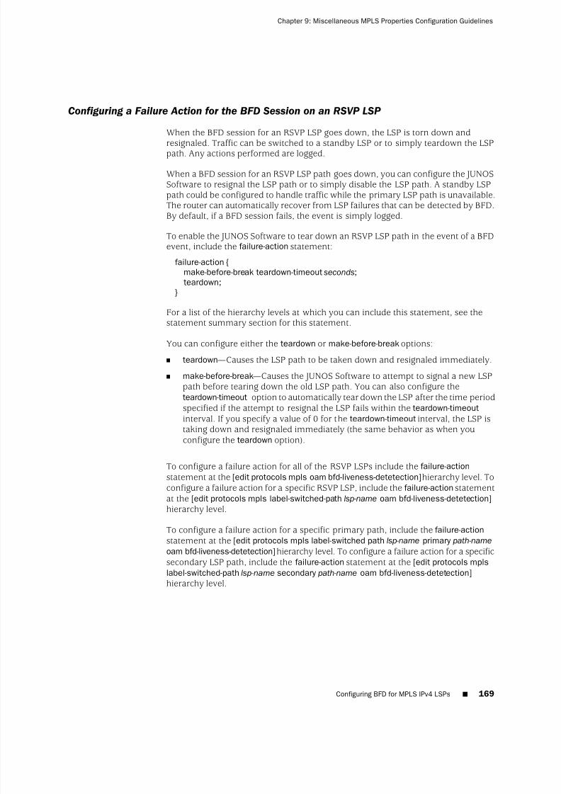
8/7/2019 Config Guide Mpls Applications
http://slidepdf.com/reader/full/config-guide-mpls-applications 207/547
Configuring a Failure Action for the BFD Session on an RSVP LSP
When the BFD session for an RSVP LSP goes down, the LSP is torn down andresignaled. Traffic can be switched to a standby LSP or to simply teardown the LSPpath. Any actions performed are logged.
When a BFD session for an RSVP LSP path goes down, you can configure the JUNOSSoftware to resignal the LSP path or to simply disable the LSP path. A standby LSPpath could be configured to handle traffic while the primary LSP path is unavailable.The router can automatically recover from LSP failures that can be detected by BFD.By default, if a BFD session fails, the event is simply logged.
To enable the JUNOS Software to tear down an RSVP LSP path in the event of a BFDevent, include the failure-action statement:
failure-action {make-before-break teardown-timeout seconds;teardown;
}
For a list of the hierarchy levels at which you can include this statement, see thestatement summary section for this statement.
You can configure either the teardown or make-before-break options:
■ teardown—Causes the LSP path to be taken down and resignaled immediately.
■ make-before-break—Causes the JUNOS Software to attempt to signal a new LSPpath before tearing down the old LSP path. You can also configure theteardown-timeout option to automatically tear down the LSP after the time periodspecified if the attempt to resignal the LSP fails within the teardown-timeout
interval. If you specify a value of 0 for the teardown-timeout interval, the LSP istaking down and resignaled immediately (the same behavior as when youconfigure the teardown option).
To configure a failure action for all of the RSVP LSPs include the failure-actionstatement at the [edit protocols mpls oam bfd-liveness-detetection] hierarchy level. Toconfigure a failure action for a specific RSVP LSP, include the failure-action statementat the [edit protocols mpls label-switched-path lsp-name oam bfd-liveness-detetection]hierarchy level.
To configure a failure action for a specific primary path, include the failure-actionstatement at the [edit protocols mpls label-switched path lsp-name primary path-name
oam bfd-liveness-detetection]hierarchy level. To configure a failure action for a specificsecondary LSP path, include the failure-action statement at the [edit protocols mpls
label-switched-path lsp-name secondary path-name oam bfd-liveness-detetection]hierarchy level.
Configuring BFD for MPLS IPv4 LSPs ■ 169
Chapter 9: Miscellaneous MPLS Properties Configuration Guidelines
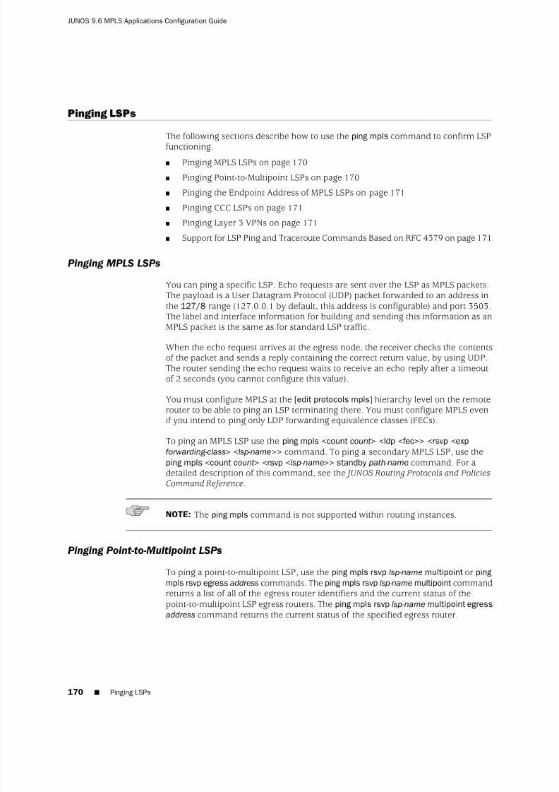
8/7/2019 Config Guide Mpls Applications
http://slidepdf.com/reader/full/config-guide-mpls-applications 208/547
Pinging LSPs
The following sections describe how to use the ping mpls command to confirm LSPfunctioning.
■ Pinging MPLS LSPs on page 170
■ Pinging Point-to-Multipoint LSPs on page 170
■ Pinging the Endpoint Address of MPLS LSPs on page 171
■ Pinging CCC LSPs on page 171
■ Pinging Layer 3 VPNs on page 171
■ Support for LSP Ping and Traceroute Commands Based on RFC 4379 on page 171
Pinging MPLS LSPs
You can ping a specific LSP. Echo requests are sent over the LSP as MPLS packets.The payload is a User Datagram Protocol (UDP) packet forwarded to an address inthe 127/8 range (127.0.0.1 by default, this address is configurable) and port 3503.The label and interface information for building and sending this information as anMPLS packet is the same as for standard LSP traffic.
When the echo request arrives at the egress node, the receiver checks the contentsof the packet and sends a reply containing the correct return value, by using UDP.The router sending the echo request waits to receive an echo reply after a timeoutof 2 seconds (you cannot configure this value).
You must configure MPLS at the [edit protocols mpls] hierarchy level on the remoterouter to be able to ping an LSP terminating there. You must configure MPLS evenif you intend to ping only LDP forwarding equivalence classes (FECs).
To ping an MPLS LSP use the ping mpls <count count> <ldp <fec>> <rsvp <expforwarding-class> <lsp-name>> command. To ping a secondary MPLS LSP, use theping mpls <count count> <rsvp <lsp-name>> standby path-name command. For adetailed description of this command, see the JUNOS Routing Protocols and PoliciesCommand Reference.
NOTE: The ping mpls command is not supported within routing instances.
Pinging Point-to-Multipoint LSPs
To ping a point-to-multipoint LSP, use the ping mpls rsvp lsp-name multipoint or pingmpls rsvp egress address commands. The ping mpls rsvp lsp-name multipoint commandreturns a list of all of the egress router identifiers and the current status of thepoint-to-multipoint LSP egress routers. The ping mpls rsvp lsp-name multipoint egressaddress command returns the current status of the specified egress router.
170 ■ Pinging LSPs
JUNOS 9.6 MPLS Applications Configuration Guide

8/7/2019 Config Guide Mpls Applications
http://slidepdf.com/reader/full/config-guide-mpls-applications 209/547
Pinging the Endpoint Address of MPLS LSPs
To determine whether an LSP between two provider edge (PE) routers is up andrunning, you can ping the endpoint address of the LSP. To ping an MPLS LSP endpoint,use the ping mpls lsp-end-point address command. This command tells you what typeof LSP (RSVP or LDP) terminates at the address specified and whether that LSP is upor down.
For a detailed description of this command, see the JUNOS Routing Protocols and Policies Command Reference.
Pinging CCC LSPs
You can ping a specific CCC LSP. The CCC LSP ping command is identical to the oneused for MPLS LSPs. The command you use is ping mpls <count count>
<rsvp <lsp-name>>. You can also ping a secondary standby CCC LSP by using theping mpls <count count> <rsvp <lsp-name>> standby path-name command.
For a detailed description of this command, see the JUNOS Routing Protocols and Policies Command Reference.
Pinging Layer 3 VPNs
You can use a similar command, ping mpls l3vpn vpn-name prefix prefix <count count>,to ping a Layer 3 VPN. For more information about this command, see the JUNOS VPNs Configuration Guide and the JUNOS Routing Protocols and Policies Command Reference.
Support for LSP Ping and Traceroute Commands Based on RFC 4379
The JUNOS Software partially supports LSP ping and traceroute commands based onRFC 4379, Detecting Multi-Protocol Label Switched (MPLS) Data Plane Failures. However,the JUNOS Software only supports this functionality on LSP transit routers. If a pingor traceroute command is issued from a router that fully supports RFC 4379, it canpropagate correctly on routers running the JUNOS Software.
LSP ping and traceroute commands based on RFC 4379 attempt to trace the pathtaken by an LSP by relying on MPLS TTL expiration. An LSP can take multiple pathsfrom ingress to egress. This occurs in particular with Equal Cost Multipath (ECMP).The LSP traceroute command can trace all possible paths to an LSP egress node.
Tracing MPLS and LSP Packets and Operations
To trace MPLS and LSP packets and operations, include the traceoptions statement:
traceoptions {file filename <files number > <size size> <world-readable | no-world-readable>;flag flag ;
}
Tracing MPLS and LSP Packets and Operations ■ 171
Chapter 9: Miscellaneous MPLS Properties Configuration Guidelines

8/7/2019 Config Guide Mpls Applications
http://slidepdf.com/reader/full/config-guide-mpls-applications 210/547
For a list of hierarchy levels at which you can include this statement, see the statementsummary section for this statement.
You can specify the following MPLS-specific flags in the MPLS traceoptions statement:
■ all—Trace all operations.
■ connection—Trace all circuit cross-connect (CCC) activity.
■ connection-detail—Trace detailed CCC activity.
■ cspf —Trace CSPF computations.
■ cspf-link—Trace links visited during CSPF computations.
■ cspf-node—Trace nodes visited during CSPF computations.
■ error—Trace MPLS error conditions.
■ graceful-restart—Trace MPLS graceful restart events.
■
lsping—
Trace LSP ping packets and return codes.■ state—Trace all LSP state transitions.
When you configure trace options to track an MPLS LSP using the cspf option, theCSPF log displays information about the MPLS LSP using the term “generalized MPLS”(GMPLS). For example, a message in the CSPF log might state that the “link passesGMPLS constraints”. Generalized MPLS (GMPLS) is a superset of MPLS, so this messageis normal and does not affect proper MPLS LSP operation.
For general information about tracing and global tracing options, see the JUNOS Routing Protocols Configuration Guide.
172 ■ Tracing MPLS and LSP Packets and Operations
JUNOS 9.6 MPLS Applications Configuration Guide
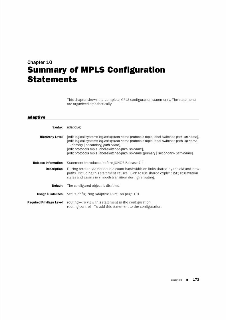
8/7/2019 Config Guide Mpls Applications
http://slidepdf.com/reader/full/config-guide-mpls-applications 211/547
Chapter 10
Summary of MPLS ConfigurationStatements
This chapter shows the complete MPLS configuration statements. The statementsare organized alphabetically.
adaptive
Syntax adaptive;
Hierarchy Level [edit logical-systems logical-system-name protocols mpls label-switched-path lsp-name],[edit logical-systems logical-system-name protocols mpls label-switched-path lsp-name
(primary | secondary) path-name],[edit protocols mpls label-switched-path lsp-name],[edit protocols mpls label-switched-path lsp-name (primary | secondary) path-name]
Release Information Statement introduced before JUNOS Release 7.4.
Description During reroute, do not double-count bandwidth on links shared by the old and newpaths. Including this statement causes RSVP to use shared explicit (SE) reservationstyles and assists in smooth transition during rerouting.
Default The configured object is disabled.
Usage Guidelines See “Configuring Adaptive LSPs” on page 101.
Required Privilege Level routing—To view this statement in the configuration.routing-control—To add this statement to the configuration.
adaptive ■ 173

8/7/2019 Config Guide Mpls Applications
http://slidepdf.com/reader/full/config-guide-mpls-applications 212/547
adjust-interval
Syntax adjust-interval seconds;
Hierarchy Level [edit logical-systems logical-system-name protocols mpls label-switched-path lsp-name
auto-bandwidth],[edit protocols mpls label-switched-path lsp-name auto-bandwidth]
Release Information Statement introduced before JUNOS Release 7.4.
Description Specify the bandwidth reallocation interval.
Options seconds—Bandwidth reallocation interval, in seconds.Range: 300 through 4,294,967,295 secondsDefault: 86,400 seconds
Usage Guidelines See “Configuring the Automatic Bandwidth Allocation Interval” on page 90.
Required Privilege Level routing—To view this statement in the configuration.routing-control—To add this statement to the configuration.
adjust-threshold
Syntax adjust-threshold percent;
Hierarchy Level [edit logical-systems logical-system-name protocols mpls label-switched-path lsp-name
auto-bandwidth],
[edit protocols mpls label-switched-path lsp-name auto-bandwidth]
Release Information Statement introduced before JUNOS Release 7.4.
Description Specify how sensitive the automatic bandwidth adjustment for a label-switched path(LSP) is to changes in bandwidth utilization.
Options percent—Bandwidth demand for the current bandwidth adjustment interval isdetermined and compared to the LSP’s current bandwidth allocation. If thepercentage difference in bandwidth is greater than or equal to the percentagespecified by this statement, the LSP’s bandwidth is adjusted to the currentbandwidth demand.
Usage Guidelines See “Configuring the Automatic Bandwidth Adjustment Threshold” on page 91.
Required Privilege Level routing—To view this statement in the configuration.routing-control—To add this statement to the configuration.
174 ■ adjust-interval
JUNOS 9.6 MPLS Applications Configuration Guide

8/7/2019 Config Guide Mpls Applications
http://slidepdf.com/reader/full/config-guide-mpls-applications 213/547
adjust-threshold-overflow-limit
Syntax adjust-threshold-overflow-limitnumber ;
Hierarchy Level [edit logical-systems logical-system-name protocols mpls label-switched-path lsp-name
auto-bandwidth],[edit protocols mpls label-switched-path lsp-name auto-bandwidth]
Release Information Statement introduced in JUNOS Release 7.5.
Description Specify the number of consecutive bandwidth overflow samples before triggering abandwidth adjustment.
Options number —Number of consecutive bandwidth overflow samples.Range: 1 through 65,535
Default: This feature is disabled by default.Usage Guidelines See “Configuring a Limit on Bandwidth Overflow Samples” on page 91.
Required Privilege Level routing—To view this statement in the configuration.routing-control—To add this statement to the configuration.
admin-down
Syntax admin-down;
Hierarchy Level [edit logical-systems logical-system-name protocols mpls label-switched-path lsp-name],
[edit protocols mpls label-switched-path lsp-name]
Release Information Statement introduced in JUNOS Release 8.2.
Description Set the A-bit in the Admin Status object. When set, this bit indicates the administrativedown status for an LSP. This feature is used specifically by non-packet GMPLS LSPs.It does not affect control path setup or data forwarding for packet LSPs.
Usage Guidelines See “Allowing Non-Packet GMPLS LSPs to Establish Paths Through Routers Runningthe JUNOS Software” on page 462.
Required Privilege Level routing—To view this statement in the configuration.routing-control—To add this statement to the configuration.
adjust-threshold-overflow-limit ■ 175
Chapter 10: Summary of MPLS Configuration Statements

8/7/2019 Config Guide Mpls Applications
http://slidepdf.com/reader/full/config-guide-mpls-applications 214/547

8/7/2019 Config Guide Mpls Applications
http://slidepdf.com/reader/full/config-guide-mpls-applications 215/547
admin-group (for LSPs)
Syntax admin-group {
exclude [ group-names ];include-all [ group-names ];include-any [ group-names ];
}
Hierarchy Level [edit logical-systems logical-system-name protocols mpls],[edit logical-systems logical-system-name protocols mpls label-switched-path lsp-name],[edit logical-systems logical-system-name protocols mpls label-switched-path lsp-name
(primary | secondary) path-name],[edit protocols mpls],[edit protocols mpls label-switched-path lsp-name],[edit protocols mpls label-switched-path lsp-name (primary | secondary) path-name]
Release Information Statement introduced before JUNOS Release 7.4.Description Define the administrative groups to include or exclude for an LSP and for a path’s
primary and secondary paths.
Options The statements are explained separately.
Usage Guidelines See “Configuring Administrative Groups” on page 96.
Required Privilege Level routing—To view this statement in the configuration.routing-control—To add this statement to the configuration.
admin-group (for LSPs) ■ 177
Chapter 10: Summary of MPLS Configuration Statements

8/7/2019 Config Guide Mpls Applications
http://slidepdf.com/reader/full/config-guide-mpls-applications 216/547
admin-groups
Syntax admin-groups { group-name group-value;
}
Hierarchy Level [edit logical-systems logical-system-name protocols mpls],[edit protocols mpls]
Release Information Statement introduced before JUNOS Release 7.4.
Description Configure administrative groups to implement link coloring of resource classes.
Options group-name—Name of the group. You can assign up to 32 names. The names andtheir corresponding values must be identical across all routers within a single
domain.
group-value—Value assigned to the group. The names and their corresponding valuesmust be identical across all routers within a single domain.Range: 0 through 31
Usage Guidelines See “Configuring Administrative Groups” on page 96.
Required Privilege Level routing—To view this statement in the configuration.routing-control—To add this statement to the configuration.
Related Topics admin-group
advertisement-hold-time
Syntax advertisement-hold-time seconds;
Hierarchy Level [edit logical-systems logical-system-name protocols mpls],[edit protocols mpls]
Release Information Statement introduced before JUNOS Release 7.4.
Description Do not advertise when the LSP goes from up to down, for a certain period of timeknown as hold time.
Options seconds—Hold time, in seconds.Range: 0 through 65,535 secondsDefault: 5 seconds
Usage Guidelines See “Damping Advertisement of LSP State Changes” on page 107.
Required Privilege Level routing—To view this statement in the configuration.routing-control—To add this statement to the configuration.
178 ■ admin-groups
JUNOS 9.6 MPLS Applications Configuration Guide

8/7/2019 Config Guide Mpls Applications
http://slidepdf.com/reader/full/config-guide-mpls-applications 217/547
allow-fragmentation
Syntax allow-fragmentation;
Hierarchy Level [edit logical-systems logical-system-name protocols mpls path-mtu],[edit protocols mpls path-mtu]
Release Information Statement introduced before JUNOS Release 7.4.
Description Allow IP packets to be fragmented before they are encapsulated in MPLS.
Usage Guidelines See “Enabling Packet Fragmentation” on page 294.
Required Privilege Level routing—To view this statement in the configuration.routing-control—To add this statement to the configuration.
associate-backup-pe-groups
Syntax associate-backup-pe-groups;
Hierarchy Level [edit logical-systems logical-system-name protocols mpls label-switched-path lsp-name],[edit protocols mpls label-switched-path lsp-name]
Release Information Statement introduced in JUNOS Release 9.0.
Description Enable an LSP to monitor the status of its destination PE router. You can configuremultiple backup PE router groups using the same router's address. Backup PE router
groups provide ingress PE router redundancy when point-to-multipoint (P2MP) LSPsare configured for multicast distribution. A failure of this LSP indicates to all of thebackup PE router groups that the destination PE router is down. This statement isnot tied to a specific backup PE router group. It applies to all groups that are interestedin the status of the LSP to the destination address.
Usage Guidelines See “Enabling Point-to-Point LSPs to Monitor Egress PE Routers” on page 147.
Required Privilege Level routing—To view this statement in the configuration.routing-control—To add this statement to the configuration.
allow-fragmentation ■ 179
Chapter 10: Summary of MPLS Configuration Statements
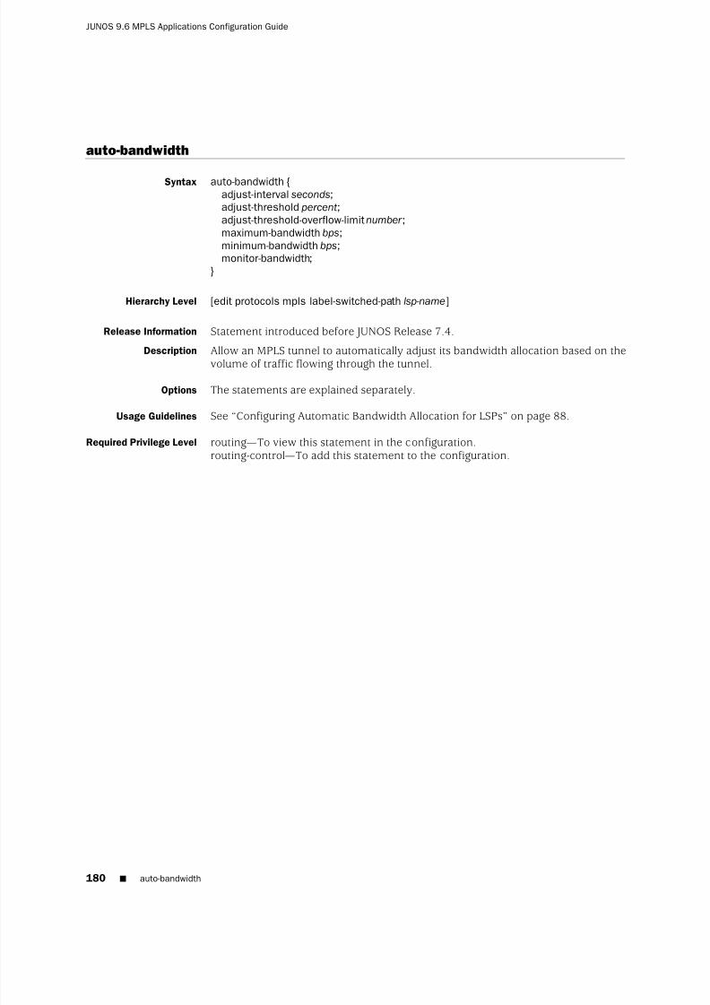
8/7/2019 Config Guide Mpls Applications
http://slidepdf.com/reader/full/config-guide-mpls-applications 218/547
auto-bandwidth
Syntax auto-bandwidth {adjust-interval seconds;adjust-threshold percent;adjust-threshold-overflow-limitnumber ;maximum-bandwidth bps;minimum-bandwidth bps;monitor-bandwidth;
}
Hierarchy Level [edit protocols mpls label-switched-path lsp-name]
Release Information Statement introduced before JUNOS Release 7.4.
Description Allow an MPLS tunnel to automatically adjust its bandwidth allocation based on thevolume of traffic flowing through the tunnel.
Options The statements are explained separately.
Usage Guidelines See “Configuring Automatic Bandwidth Allocation for LSPs” on page 88.
Required Privilege Level routing—To view this statement in the configuration.routing-control—To add this statement to the configuration.
180 ■ auto-bandwidth
JUNOS 9.6 MPLS Applications Configuration Guide

8/7/2019 Config Guide Mpls Applications
http://slidepdf.com/reader/full/config-guide-mpls-applications 219/547
auto-policing
Syntax auto-policing {class all (drop | loss-priority-high | loss-priority-low);class ctnumber (drop | loss-priority-high | loss-priority-low);
}
Hierarchy Level [edit logical-systems logical-system-name protocols mpls],[edit protocols mpls]
Release Information Statement introduced before JUNOS Release 7.4.
Description Enable the automatic policing of all the MPLS LSPs on the router or logical system.
Options class all—Apply the same policer action to all the class types (ct0, ct1, ct2, and ct3).
class ctnumber —Specific class type (ct0, ct1, ct2, or ct3) to which to apply a policeraction.
Policer actions—You can specify the following policer actions:Default: no action
■ drop—Drop all packets.
■ loss-priority-high—Set the packet loss priority (PLP) to high.
■ loss-priority-low—Set the PLP to low.
Usage Guidelines See “Configuring Automatic Policers” on page 162.
Required Privilege Level routing—To view this statement in the configuration.routing-control—To add this statement to the configuration.
Related Topics policing
auto-policing ■ 181
Chapter 10: Summary of MPLS Configuration Statements

8/7/2019 Config Guide Mpls Applications
http://slidepdf.com/reader/full/config-guide-mpls-applications 220/547
backup-pe-group
Syntax backup-pe-group pe-group-name {backups [ addresses ];local-address address;
}
Hierarchy Level [edit logical-systems logical-system-name routing-instances routing-instance-name
routing-options multicast],[edit logical-systems logical-system-name routing-options multicast],[edit routing-instances routing-instance-name routing-options multicast],[edit routing-options multicast]
Release Information Statement introduced in JUNOS Release 9.0.
Description Configure a backup provider edge (PE) group for ingress PE router redundancy whenpoint-to-multipoint (P2MP) label-switched paths (LSPs) are used for multicastdistribution.
Options backups addresses—Specify the address of backup PE routers for ingress PEredundancy when point-to-multipoint LSPs are used for multicast distribution.
local-address address—Specify the address of the local PE router for ingress PEredundancy when point-to-multipoint LSPs are used for multicast distribution.
pe-group-name—Specify the name for the group of PE routers that provide ingressPE router redundancy for P2MP LSPs.
Usage Guidelines
See“
Configuring Ingress PE Router Redundancy for Point-to-Multipoint LSPs”
onpage 146.
Required Privilege Level routing—To view this statement in the configuration.routing-control—To add this statement to the configuration.
182 ■ backup-pe-group
JUNOS 9.6 MPLS Applications Configuration Guide

8/7/2019 Config Guide Mpls Applications
http://slidepdf.com/reader/full/config-guide-mpls-applications 221/547
bandwidth
Syntax bandwidth bps {ct0 bps;ct1 bps;ct2 bps;ct3 bps;
}
Hierarchy Level [edit logical-systems logical-system-name protocols mpls],[edit logical-systems logical-system-name protocols mpls label-switched-path lsp-name],[edit logical-systems logical-system-name protocols mpls label-switched-path lsp-name
fast-reroute],[edit logical-systems logical-system-name protocols mpls label-switched-path lsp-name
(primary | secondary) path-name],
[edit protocols mpls],[edit protocols mpls label-switched-path lsp-name],[edit protocols mpls label-switched-path lsp-name fast-reroute],[edit protocols mpls label-switched-path lsp-name (primary | secondary) path-name]
Release Information Statement introduced before JUNOS Release 7.4.
Description When configuring an LSP, specify the traffic rate associated with the LSP.
When configuring fast reroute, allocate bandwidth for the reroute path. By default,no bandwidth is reserved for the rerouted path. The fast reroute bandwidth does notneed to be identical to that allocated for the LSP itself.
When configuring a multiclass LSP, use the ctnumber bandwidth statements to specifythe bandwidth to be allocated for each class type.
Options bps—Bandwidth, in bits per second. You can specify this as an integer value. Youcan also use the abbreviations k (for a thousand), m (for a million), or g (for abillion).Range: Any positive integerDefault: 0 (no bandwidth is reserved)
ctnumber bps—Bandwidth for the specified class type, in bits per second. You canspecify this as an integer value. If you do so, count your zeros carefully, or youcan use the abbreviations k (for a thousand), m (for a million), or g (for a billion[also called a thousand million]).Range: Any positive integer
Default: 0 (no bandwidth is reserved)Usage Guidelines See “Configuring Fast Reroute” on page 78, “Configuring the Bandwidth Value for
LSPs” on page 106, “Configuring Traffic-Engineered LSPs” on page 127, and“Configuring Class-Type Bandwidth Constraints for Multiclass LSPs” on page 129.
Required Privilege Level routing—To view this statement in the configuration.routing-control—To add this statement to the configuration.
bandwidth ■ 183
Chapter 10: Summary of MPLS Configuration Statements

8/7/2019 Config Guide Mpls Applications
http://slidepdf.com/reader/full/config-guide-mpls-applications 222/547
bandwidth-model
Syntax bandwidth-model {extended-mam;mam;rdm;
}
Hierarchy Level [edit logical-systems logical-system-name protocols mpls diffserv-te],[edit protocols mpls diffserv-te]
Release Information Statement introduced before JUNOS Release 7.4.
Description Configure the bandwidth model for differentiated services. Note that you cannotconfigure both bandwidth models at the same time.
Options extended-mam—The extended maximum allocation model (MAM) is a bandwidthmodel based on MAM.
mam—The MAM is defined in RFC 4125, Maximum Allocation Bandwidth ConstraintsModel for Diffserv-aware MPLS Traffic Engineering.
rdm—The Russian dolls bandwidth allocation model (RDM) is defined in RFC 4127, Russian Dolls Bandwidth Constraints Model for Diffserv-aware MPLS Traffic Engineering. RDM makes efficient use of bandwidth by allowing the class typesto share bandwidth.
Usage Guidelines See “Configuring the Bandwidth Model” on page 116.
Required Privilege Level routing—To view this statement in the configuration.routing-control—To add this statement to the configuration.
184 ■ bandwidth-model
JUNOS 9.6 MPLS Applications Configuration Guide
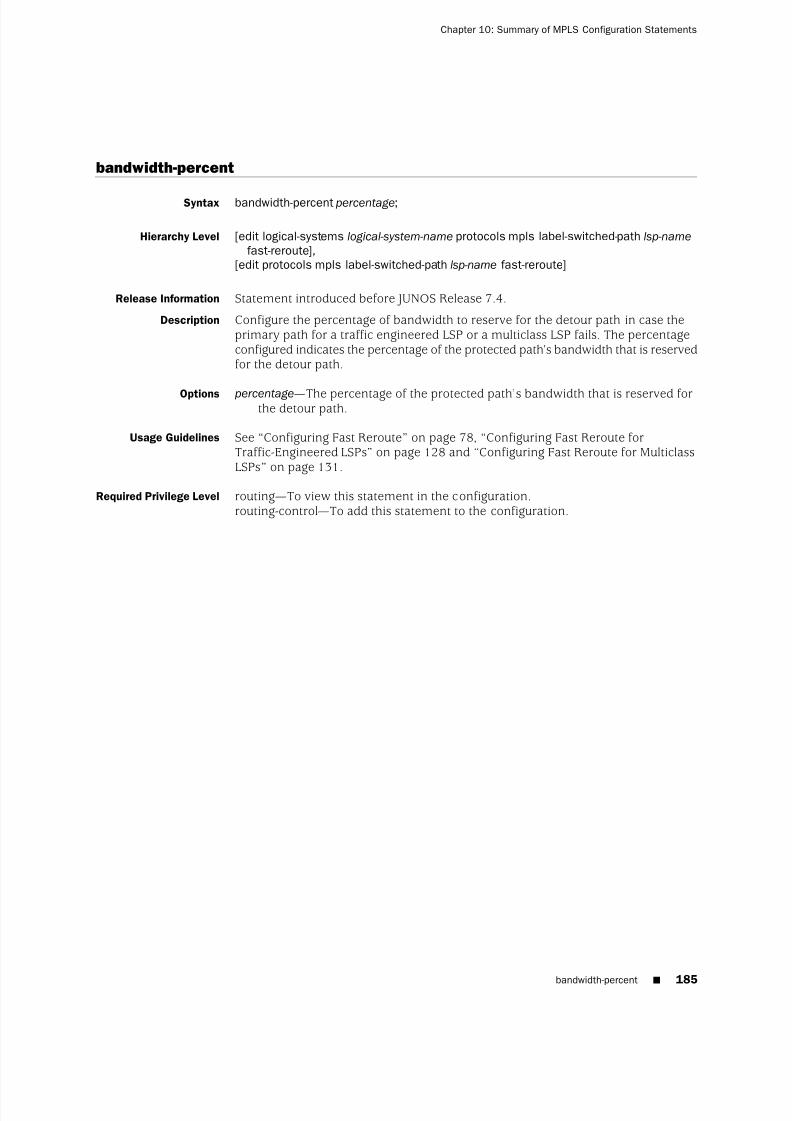
8/7/2019 Config Guide Mpls Applications
http://slidepdf.com/reader/full/config-guide-mpls-applications 223/547
bandwidth-percent
Syntax bandwidth-percent percentage;
Hierarchy Level [edit logical-systems logical-system-name protocols mpls label-switched-path lsp-name
fast-reroute],[edit protocols mpls label-switched-path lsp-name fast-reroute]
Release Information Statement introduced before JUNOS Release 7.4.
Description Configure the percentage of bandwidth to reserve for the detour path in case theprimary path for a traffic engineered LSP or a multiclass LSP fails. The percentageconfigured indicates the percentage of the protected path’s bandwidth that is reservedfor the detour path.
Options percentage—The percentage of the protected path’s bandwidth that is reserved forthe detour path.
Usage Guidelines See “Configuring Fast Reroute” on page 78, “Configuring Fast Reroute forTraffic-Engineered LSPs” on page 128 and “Configuring Fast Reroute for MulticlassLSPs” on page 131.
Required Privilege Level routing—To view this statement in the configuration.routing-control—To add this statement to the configuration.
bandwidth-percent ■ 185
Chapter 10: Summary of MPLS Configuration Statements

8/7/2019 Config Guide Mpls Applications
http://slidepdf.com/reader/full/config-guide-mpls-applications 224/547
bfd-liveness-detection
Syntax bfd-liveness-detection {failure-action {
make-before-break teardown-timeout seconds;teardown;
}minimum-interval milliseconds;minimum-receive-interval milliseconds;minimum-transmit-interval milliseconds;multiplier detection-time-multiplier ;
}
Hierarchy Level [edit protocols mpls label-switched-path lsp-name oam],[edit protocols mpls oam]
Release Information Statement introduced in JUNOS Release 7.6. The failure-action statement option wasadded in JUNOS Release 8.5.
Description Enable Bidirectional Forwarding Detection (BFD) for all of the MPLS LSPs or for justa specific LSP.
Options minimum-interval—Minimum transmit and receive interval.Range: 50 through 255,000 millisecondsDefault: 50
minimum-receive-interval—Minimum receive interval.Range: 50 through 255,000 milliseconds
Default: 50minimum-transmit-interval—Minimum transmit interval.
Range: 50 through 255,000 millisecondsDefault: 50
multiplier—Detection time multiplier.Range: 1 through 255Default: 3
The failure-action statement is explained separately.
Usage Guidelines See “Configuring BFD for MPLS IPv4 LSPs” on page 167.
Required Privilege Level routing—To view this statement in the configuration.routing-control—To add this statement to the configuration.
186 ■ bfd-liveness-detection
JUNOS 9.6 MPLS Applications Configuration Guide

8/7/2019 Config Guide Mpls Applications
http://slidepdf.com/reader/full/config-guide-mpls-applications 225/547
class-of-service
Syntax class-of-service cos-value;
Hierarchy Level [edit logical-systems logical-system-name protocols mpls],[edit logical-systems logical-system-name protocols mpls interface interface-name
label-map (default-route | in-label)],[edit logical-systems logical-system-name protocols mpls label-switched-path lsp-name],[edit logical-systems logical-system-name protocols mpls label-switched-path lsp-name
(primary | secondary) path-name],[edit logical-systems logical-system-name protocols mpls static-path inet address],[edit protocols mpls],[edit protocols mpls interface interface-name label-map (default-route | in-label)],[edit protocols mpls label-switched-path lsp-name],[edit protocols mpls label-switched-path lsp-name (primary | secondary) path-name],
[edit protocols mpls static-path inet address]
Release Information Statement introduced before JUNOS Release 7.4.
Description Class-of-service (CoS) value given to all packets in the LSP.
The CoS value might affect the scheduling or queuing algorithm of traffic travelingalong an LSP.
Options cos-value—CoS value. A higher value typically corresponds to a higher level of service.Range: 0 through 7Default: If you do not specify a CoS value, the IP precedence bits from thepacket’s IP header are used as the packet’s CoS value.
Usage Guidelines See “Configuring Class of Service for MPLS LSPs” on page 98, “Configuring the IngressRouter for Static LSPs” on page 133, and “Configuring the Intermediate and EgressRouters for Static LSPs” on page 136.
Required Privilege Level routing—To view this statement in the configuration.routing-control—To add this statement to the configuration.
class-of-service ■ 187
Chapter 10: Summary of MPLS Configuration Statements

8/7/2019 Config Guide Mpls Applications
http://slidepdf.com/reader/full/config-guide-mpls-applications 226/547
default-route
Syntax default-route {class-of-service cos-value;(next-hop (address | interface-name | address /interface-name) | (discard | reject);(pop | swap out-label);preference preference;swap-push swap-label push-label;
}
Hierarchy Level [edit logical-systems logical-system-name protocols mpls interface (interface-name | all)label-map],
[edit protocols mpls interface (interface-name | all) label-map]
Release Information Statement introduced before JUNOS Release 7.4.
Description Process MPLS packets that have not been assigned label values and have nocorresponding entry in the mpls.0 table.
The remaining statements are explained separately.
Usage Guidelines See “Configuring a Default Route for Unlabeled MPLS Packets” on page 60.
Required Privilege Level routing—To view this statement in the configuration.routing-control—To add this statement to the configuration.
description
Syntax description text;
Hierarchy Level [edit logical-systems logical-system-name protocols mpls label-switched-path lsp-name],[edit protocols mpls label-switched-path lsp-name]
Release Information Statement introduced before JUNOS Release 7.4.
Description Provides a textual description of the LSP. Enclose any descriptive text that includesspaces in quotation marks (" "). Any descriptive text you include is displayed in theoutput of the show mpls lsp detail command and has no effect on the operation of the LSP.
Options text—
Provide a textual description of the LSP.
Usage Guidelines See “Configuring a Text Description for LSPs” on page 78.
Required Privilege Level routing—To view this statement in the configuration.routing-control—To add this statement to the configuration.
188 ■ default-route
JUNOS 9.6 MPLS Applications Configuration Guide

8/7/2019 Config Guide Mpls Applications
http://slidepdf.com/reader/full/config-guide-mpls-applications 227/547

8/7/2019 Config Guide Mpls Applications
http://slidepdf.com/reader/full/config-guide-mpls-applications 228/547
disable
Syntax disable;
Hierarchy Level [edit logical-systems logical-system-name protocols mpls],[edit logical-systems logical-system-name protocols mpls interface interface-name],[edit logical-systems logical-system-name protocols mpls label-switched-path lsp-name],[edit logical-systems logical-system-name protocols mpls label-switched-path lsp-name
auto-bandwidth],[edit protocols mpls],[edit protocols mpls interface interface-name],[edit protocols mpls label-switched-path lsp-name]
Release Information Statement introduced before JUNOS Release 7.4.
Description Disable the functionality of the configured object.
Default The configured object is enabled (operational) unless explicitly disabled.
Usage Guidelines See “LSP Configuration Overview” on page 70.
Required Privilege Level routing—To view this statement in the configuration.routing-control—To add this statement to the configuration.
discard
Syntax discard;
Hierarchy Level [edit logical-systems logical-system-name protocols mpls interface interface-name
label-map (default-route | in-label)],[edit protocols mpls interface interface-name label-map (default-route | in-label)],
Release Information Statement introduced before JUNOS Release 7.4.
Description Do not forward packets that match the incoming label. Instead, drop the packetsand do not send an Internet Control Message Protocol (ICMP) unreachable message.
Usage Guidelines See “Configuring the Intermediate and Egress Routers for Static LSPs” on page 136.
Required Privilege Level routing—To view this statement in the configuration.
routing-control—
To add this statement to the configuration.
190 ■ disable
JUNOS 9.6 MPLS Applications Configuration Guide
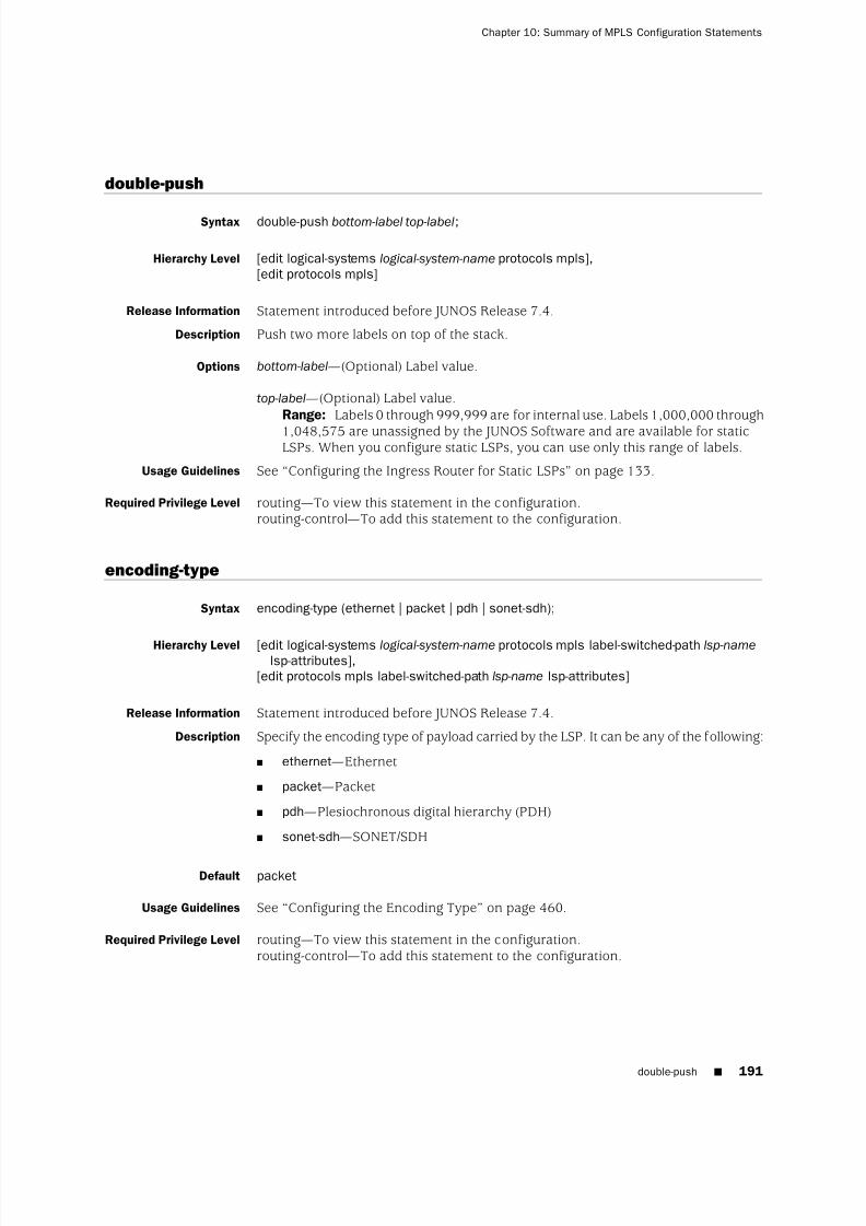
8/7/2019 Config Guide Mpls Applications
http://slidepdf.com/reader/full/config-guide-mpls-applications 229/547
double-push
Syntax double-push bottom-label top-label;
Hierarchy Level [edit logical-systems logical-system-name protocols mpls],[edit protocols mpls]
Release Information Statement introduced before JUNOS Release 7.4.
Description Push two more labels on top of the stack.
Options bottom-label—(Optional) Label value.
top-label—(Optional) Label value.Range: Labels 0 through 999,999 are for internal use. Labels 1,000,000 through
1,048,575 are unassigned by the JUNOS Software and are available for staticLSPs. When you configure static LSPs, you can use only this range of labels.
Usage Guidelines See “Configuring the Ingress Router for Static LSPs” on page 133.
Required Privilege Level routing—To view this statement in the configuration.routing-control—To add this statement to the configuration.
encoding-type
Syntax encoding-type (ethernet | packet | pdh | sonet-sdh);
Hierarchy Level [edit logical-systems logical-system-name protocols mpls label-switched-path lsp-namelsp-attributes],
[edit protocols mpls label-switched-path lsp-name lsp-attributes]
Release Information Statement introduced before JUNOS Release 7.4.
Description Specify the encoding type of payload carried by the LSP. It can be any of the following:
■ ethernet—Ethernet
■ packet—Packet
■ pdh—Plesiochronous digital hierarchy (PDH)
■ sonet-sdh—SONET/SDH
Default packet
Usage Guidelines See “Configuring the Encoding Type” on page 460.
Required Privilege Level routing—To view this statement in the configuration.routing-control—To add this statement to the configuration.
double-push ■ 191
Chapter 10: Summary of MPLS Configuration Statements

8/7/2019 Config Guide Mpls Applications
http://slidepdf.com/reader/full/config-guide-mpls-applications 230/547
exclude
See the following sections:
■ exclude (for Administrative Groups) on page 192
■ exclude (for Fast Reroute) on page 193
exclude (for Administrative Groups)
Syntax exclude [ group-names ];
Hierarchy Level [edit logical-systems logical-system-name protocols mpls label-switched-path lsp-name
admin-group],[edit logical-systems logical-system-name protocols mpls label-switched-path lsp-name
(primary | secondary) path-name admin-group],
[edit protocols mpls label-switched-path lsp-name admin-group],[edit protocols mpls label-switched-path lsp-name (primary | secondary) path-name
admin-group]
Release Information Statement introduced before JUNOS Release 7.4.
Description Define the administrative groups to exclude for an LSP or for a path’s primary andsecondary paths.
Options group-names—Names of one or more groups defined with the admin-groups statement.
Usage Guidelines See “Configuring Administrative Groups” on page 96.
Required Privilege Level
routing—
To view this statement in the configuration.routing-control—To add this statement to the configuration.
192 ■ exclude (for Administrative Groups)
JUNOS 9.6 MPLS Applications Configuration Guide

8/7/2019 Config Guide Mpls Applications
http://slidepdf.com/reader/full/config-guide-mpls-applications 231/547
exclude (for Fast Reroute)
Syntax (exclude [ group-names ] | no-exclude);
Hierarchy Level [edit logical-systems logical-system-name protocols mpls label-switched-path lsp-name
fast-reroute],[edit protocols mpls label-switched-path lsp-name fast-reroute]
Release Information Statement introduced before JUNOS Release 7.4.
Description Control exclusion of administrative groups:
■ exclude—Define the administrative groups to exclude for fast reroute.
■ no-exclude—Disable administrative group exclusion.
Options group-names—Names of one or more groups defined with the admin-groups statement.
Usage Guidelines See “Configuring Fast Reroute” on page 78.
Required Privilege Level routing—To view this statement in the configuration.routing-control—To add this statement to the configuration.
Related Topics admin-groups
expand-loose-hop
Syntax expand-loose-hop;
Hierarchy Level [edit logical-systems logical-system-name protocols mpls],[edit protocols mpls]
Release Information Statement introduced in JUNOS Release 7.6.
Description Allow an LSP to traverse multiple OSPF areas within a service provider’s network.
Usage Guidelines See “Enabling Interarea Traffic Engineering” on page 152.
Required Privilege Level routing—To view this statement in the configuration.routing-control—To add this statement to the configuration.
exclude (for Fast Reroute) ■ 193
Chapter 10: Summary of MPLS Configuration Statements

8/7/2019 Config Guide Mpls Applications
http://slidepdf.com/reader/full/config-guide-mpls-applications 232/547
explicit-null
Syntax explicit-null;
Hierarchy Level [edit logical-systems logical-system-name protocols mpls],[edit protocols mpls]
Release Information Statement introduced before JUNOS Release 7.4.
Description Advertise label 0 to the egress router of an LSP.
Default If you do not include the explicit-null statement in the MPLS configuration, label 3(implicit null) is advertised.
Usage Guidelines See “Configuring RSVP to Pop the Label on the Ultimate-Hop Router” on page 295.
Required Privilege Level routing—To view this statement in the configuration.routing-control—To add this statement to the configuration.
194 ■ explicit-null
JUNOS 9.6 MPLS Applications Configuration Guide
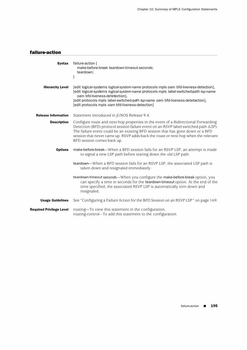
8/7/2019 Config Guide Mpls Applications
http://slidepdf.com/reader/full/config-guide-mpls-applications 233/547
failure-action
Syntax failure-action {make-before-break teardown-timeout seconds;teardown;
}
Hierarchy Level [edit logical-systems logical-system-name protocols mpls oam bfd-liveness-detection],[edit logical-systems logical-system-name protocols mpls label-switched-path lsp-name
oam bfd-liveness-detetection],[edit protocols mpls label-switched-path lsp-name oam bfd-liveness-detetection],[edit protocols mpls oam bfd-liveness-detection]
Release Information Statement introduced in JUNOS Release 9.4.
Description Configure route and next-hop properties in the event of a Bidirectional ForwardingDetection (BFD) protocol session failure event on an RSVP label-switched path (LSP).The failure event could be an existing BFD session that has gone down or a BFDsession that never came up. RSVP adds back the route or next hop when the relevantBFD session comes back up.
Options make-before-break—When a BFD session fails for an RSVP LSP, an attempt is madeto signal a new LSP path before tearing down the old LSP path.
teardown—When a BFD session fails for an RSVP LSP, the associated LSP path istaken down and resignaled immediately.
teardown-timeout seconds—When you configure the make-before-break option, you
can specify a time in seconds for the teardown-timeout option. At the end of thetime specified, the associated RSVP LSP is automatically torn down andresignaled.
Usage Guidelines See “Configuring a Failure Action for the BFD Session on an RSVP LSP” on page 169.
Required Privilege Level routing—To view this statement in the configuration.routing-control—To add this statement to the configuration.
failure-action ■ 195
Chapter 10: Summary of MPLS Configuration Statements

8/7/2019 Config Guide Mpls Applications
http://slidepdf.com/reader/full/config-guide-mpls-applications 234/547
fast-reroute
Syntax fast-reroute {(bandwidth bps | bandwidth-percent percentage);(exclude [ group-names ] | no-exclude);hop-limit number ;(include-all [ group-names ] | no-include-all);(include-any [ group-names ] | no-include-any);
}
Hierarchy Level [edit logical-systems logical-system-name protocols mpls label-switched-path lsp-name],[edit protocols mpls label-switched-path lsp-name]
Release Information Statement introduced before JUNOS Release 7.4.
Description Establish detours for the LSP so that if a node or link in the LSP fails, the traffic onthe LSP can be rerouted with minimal packet loss.
Options The statements are explained separately.
Usage Guidelines See “Configuring Fast Reroute” on page 78.
Required Privilege Level routing—To view this statement in the configuration.routing-control—To add this statement to the configuration.
196 ■ fast-reroute
JUNOS 9.6 MPLS Applications Configuration Guide

8/7/2019 Config Guide Mpls Applications
http://slidepdf.com/reader/full/config-guide-mpls-applications 235/547
fate-sharing
Syntax fate-sharing {group group-name {
cost value;from address <to address>;
}}
Hierarchy Level [edit logical-systems logical-system-name routing-options],[edit logical-systems logical-system-name routing-instances routing-instance-name
routing-options],[edit routing-options],[edit routing-instances routing-instance-name routing-options]
Release Information Statement introduced before JUNOS Release 7.4.
Description Specify groups of objects that share characteristics resulting in backup paths to beused if primary paths fail. All objects are treated as /32 host addresses. You specifyone or more objects within a group. The objects can be LAN interfaces, router IDs,or point-to-point links. The sequence is insignificant.
Options cost value—Cost assigned to the group.Range: 1 through 65,535Default: 1
from address—Address of the router or address of the LAN/NBMA interface. Forexample, an Ethernet network with four hosts in the same fate-sharing group
would require you to list all four of the separate from addresses in the group.group group-name—Each fate-sharing group must have a name, which can have a
maximum of 32 characters, including letters, numbers, periods (.), and hyphens(-). You can define up to 512 groups.
to address—(Optional) Address of egress router. For point-to-point link objects, youmust specify both a from and a to address.
Usage Guidelines See “Configuring Alternate Backup Paths Using Fate Sharing” on page 54.
Required Privilege Level routing—To view this statement in the configuration.routing-control—To add this statement to the configuration.
fate-sharing ■ 197
Chapter 10: Summary of MPLS Configuration Statements
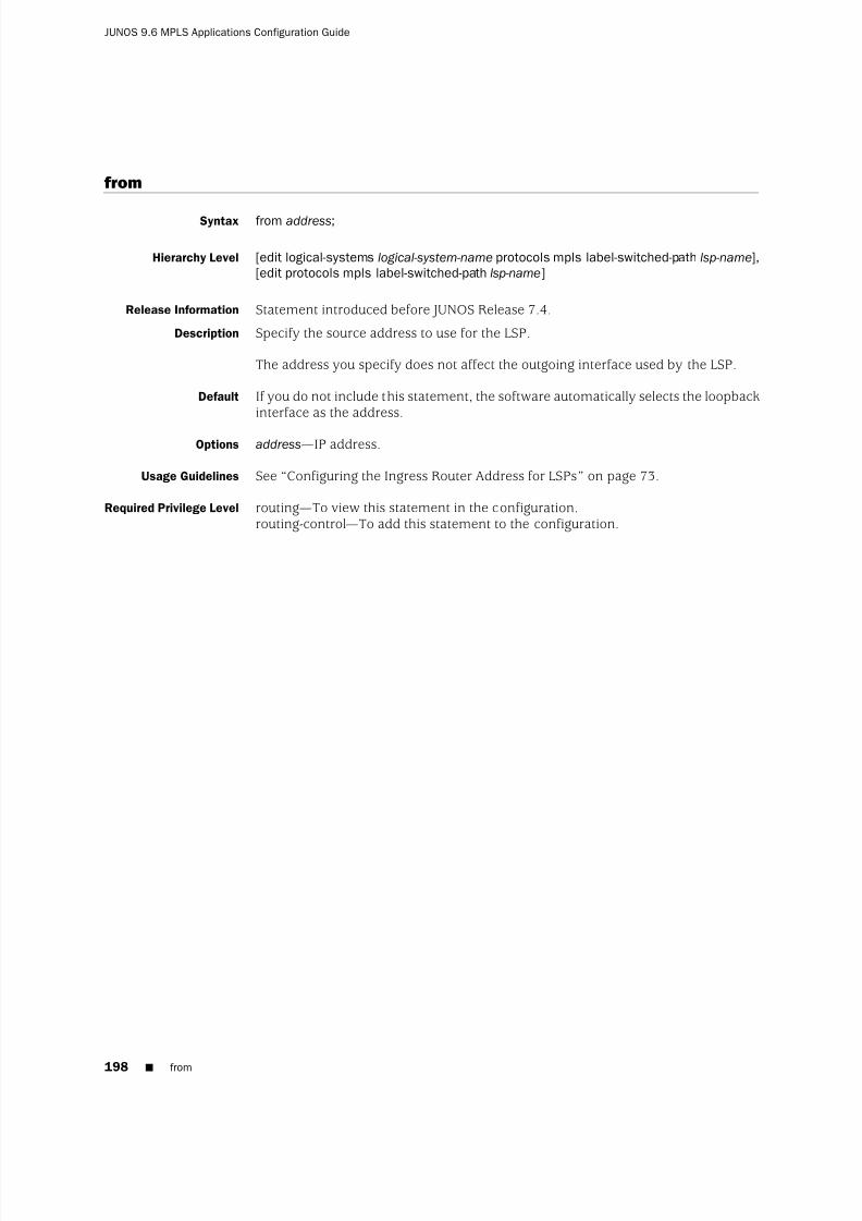
8/7/2019 Config Guide Mpls Applications
http://slidepdf.com/reader/full/config-guide-mpls-applications 236/547
from
Syntax from address;
Hierarchy Level [edit logical-systems logical-system-name protocols mpls label-switched-path lsp-name],[edit protocols mpls label-switched-path lsp-name]
Release Information Statement introduced before JUNOS Release 7.4.
Description Specify the source address to use for the LSP.
The address you specify does not affect the outgoing interface used by the LSP.
Default If you do not include this statement, the software automatically selects the loopbackinterface as the address.
Options address—IP address.
Usage Guidelines See “Configuring the Ingress Router Address for LSPs” on page 73.
Required Privilege Level routing—To view this statement in the configuration.routing-control—To add this statement to the configuration.
198 ■ from
JUNOS 9.6 MPLS Applications Configuration Guide

8/7/2019 Config Guide Mpls Applications
http://slidepdf.com/reader/full/config-guide-mpls-applications 237/547
gpid
Syntax gpid (ethernet | hdlc | ipv4 | pos-scrambling-crc-16 | pos-no-scrambling-crc-16 |pos-scrambling-crc-32 | pos-no-scrambling-crc-32 | ppp);
Hierarchy Level [edit logical-systems logical-system-name protocols mpls label-switched-path lsp-name
lsp-attributes],[edit protocols mpls label-switched-path lsp-name lsp-attributes]
Release Information Statement introduced before JUNOS Release 7.4.pos-scrambling-crc-16, pos-no-scrambling-crc-16, pos-scrambling-crc-32, andpos-no-scrambling-crc-32options added in JUNOS Release 8.0.
Description Specify the type of payload carried by the LSP. It can be any of the following:
■
ethernet—
Ethernet (GPID value: 33)■ hdlc—High-level Data Link Control (HDLC) (GPID value: 44)
■ ipv4—IP version 4 (GPID value: 0x0800)
■ pos-no-scrambling-crc-16—for interoperability with other vendors’ equipment(GPID value: 29)
■ pos-no-scrambling-crc-32—for interoperability with other vendors’ equipment(GPID value: 30)
■ pos-scrambling-crc-16—for interoperability with other vendors’ equipment (GPIDvalue: 31)
■ pos-scrambling-crc-32—for interoperability with other vendors’ equipment (GPID
value: 32)■ ppp—Point-to-Point Protocol (PPP) (GPID value: 50)
Default ipv4
Usage Guidelines See “Configuring the GPID” on page 461.
Required Privilege Level routing—To view this statement in the configuration.routing-control—To add this statement to the configuration.
gpid ■ 199
Chapter 10: Summary of MPLS Configuration Statements

8/7/2019 Config Guide Mpls Applications
http://slidepdf.com/reader/full/config-guide-mpls-applications 238/547
hop-limit
Syntax hop-limit number ;
Hierarchy Level [edit logical-systems logical-system-name protocols mpls],[edit logical-systems logical-system-name protocols mpls label-switched-path lsp-name],[edit logical-systems logical-system-name protocols mpls label-switched-path lsp-name
fast-reroute],[edit logical-systems logical-system-name protocols mpls label-switched-path lsp-name
(primary | secondary) path-name],[edit protocols mpls],[edit protocols mpls label-switched-path lsp-name],[edit protocols mpls label-switched-path lsp-name fast-reroute],[edit protocols mpls label-switched-path lsp-name (primary | secondary) path-name]
Release Information Statement introduced before JUNOS Release 7.4.
Description For an LSP, specify the maximum number of routers that the LSP can traverse,including the ingress and egress routers.
For fast reroute, how many more routers a detour is allowed to traverse comparedwith the LSP itself. For example, if an LSP traverses 4 routers, any detour for the LSPcan be no more than 10 router hops, including the ingress and egress routers.
Options number —Maximum number of hops.Range: 2 through 255 (for an LSP); 0 through 255 (for fast reroute)Default: 255 (for an LSP); 6 (for fast reroute)
Usage Guidelines See “Configuring Fast Reroute” on page 78 and “Limiting the Number of Hops in
LSPs” on page 105.
Required Privilege Level routing—To view this statement in the configuration.routing-control—To add this statement to the configuration.
icmp-tunneling
Syntax icmp-tunneling;
Hierarchy Level [edit logical-systems logical-system-name protocols mpls],[edit protocols mpls]
Release Information Statement introduced before JUNOS Release 7.4.
Description Enable ICMP tunneling, which can be used for debugging and tracing purposes.
Usage Guidelines See “Configuring ICMP Message Tunneling” on page 67.
Required Privilege Level routing—To view this statement in the configuration.routing-control—To add this statement to the configuration.
200 ■ hop-limit
JUNOS 9.6 MPLS Applications Configuration Guide

8/7/2019 Config Guide Mpls Applications
http://slidepdf.com/reader/full/config-guide-mpls-applications 239/547
include-all
See the following sections:
■ include-all (for Administrative Groups) on page 201
■ include-all (for Fast Reroute) on page 202
include-all (for Administrative Groups)
Syntax include-all [ group-names ];
Hierarchy Level [edit logical-systems logical-system-name protocols mpls label-switched-path lsp-name
admin-group],[edit logical-systems logical-system-name protocols mpls label-switched-path lsp-name
(primary | secondary) path-name admin-group],
[edit protocols mpls label-switched-path lsp-name admin-group],[edit protocols mpls label-switched-path lsp-name (primary | secondary) path-name
admin-group]
Release Information Statement introduced before JUNOS Release 7.4.
Description Require the LSP to traverse links that include all of the defined administrative groups.
Options group-names—One or more names of groups defined with the admin-groups statement.
Usage Guidelines See “Configuring Administrative Groups” on page 96.
Required Privilege Level routing—To view this statement in the configuration.
routing-control—
To add this statement to the configuration.Related Topics admin-groups
include-all (for Administrative Groups) ■ 201
Chapter 10: Summary of MPLS Configuration Statements

8/7/2019 Config Guide Mpls Applications
http://slidepdf.com/reader/full/config-guide-mpls-applications 240/547
include-all (for Fast Reroute)
Syntax (include-all [ group-names ] | no-include-all);
Hierarchy Level [edit logical-systems logical-system-name protocols mpls label-switched-path lsp-name
fast-reroute],[edit protocols mpls label-switched-path lsp-name fast-reroute]
Release Information Statement introduced before JUNOS Release 7.4.
Description Control inclusion of administrative groups:
■ include-all—Define the administrative groups that must all be included for fastreroute.
■ no-include-all—Disable administrative group inclusion.
Options group-names—One or more names of groups defined with the admin-groups statement.
Usage Guidelines See “Configuring Fast Reroute” on page 78.
Required Privilege Level routing—To view this statement in the configuration.routing-control—To add this statement to the configuration.
202 ■ include-all (for Fast Reroute)
JUNOS 9.6 MPLS Applications Configuration Guide
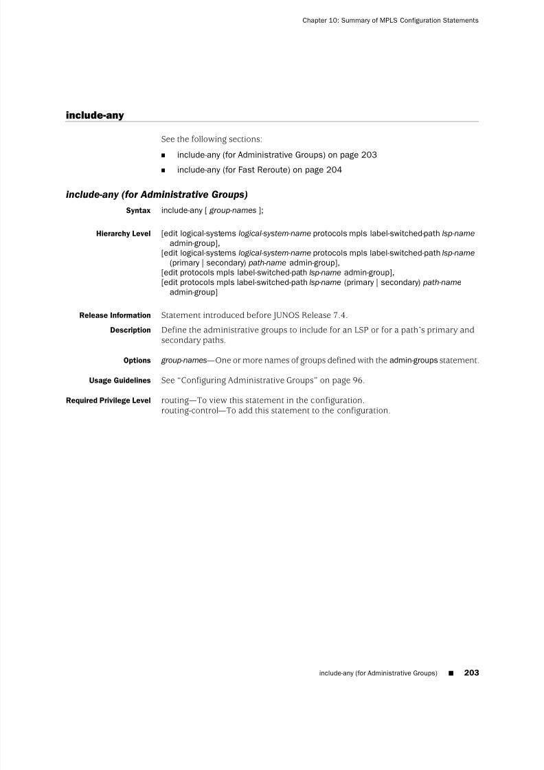
8/7/2019 Config Guide Mpls Applications
http://slidepdf.com/reader/full/config-guide-mpls-applications 241/547
include-any
See the following sections:
■ include-any (for Administrative Groups) on page 203
■ include-any (for Fast Reroute) on page 204
include-any (for Administrative Groups)
Syntax include-any [ group-names ];
Hierarchy Level [edit logical-systems logical-system-name protocols mpls label-switched-path lsp-name
admin-group],[edit logical-systems logical-system-name protocols mpls label-switched-path lsp-name
(primary | secondary) path-name admin-group],
[edit protocols mpls label-switched-path lsp-name admin-group],[edit protocols mpls label-switched-path lsp-name (primary | secondary) path-name
admin-group]
Release Information Statement introduced before JUNOS Release 7.4.
Description Define the administrative groups to include for an LSP or for a path’s primary andsecondary paths.
Options group-names—One or more names of groups defined with the admin-groups statement.
Usage Guidelines See “Configuring Administrative Groups” on page 96.
Required Privilege Level
routing—
To view this statement in the configuration.routing-control—To add this statement to the configuration.
include-any (for Administrative Groups) ■ 203
Chapter 10: Summary of MPLS Configuration Statements

8/7/2019 Config Guide Mpls Applications
http://slidepdf.com/reader/full/config-guide-mpls-applications 242/547
include-any (for Fast Reroute)
Syntax (include-any [ group-names ] | no-include-any);
Hierarchy Level [edit logical-systems logical-system-name protocols mpls label-switched-path lsp-name
fast-reroute],[edit protocols mpls label-switched-path lsp-name fast-reroute]
Release Information Statement introduced before JUNOS Release 7.4.
Description Control inclusion of administrative groups:
■ include-any—Define the administrative groups to include for fast reroute.
■ no-include-any—Disable administrative group inclusion.
Options group-names—One or more names of groups defined with the admin-groups statement.
Usage Guidelines See “Configuring Fast Reroute” on page 78.
Required Privilege Level routing—To view this statement in the configuration.routing-control—To add this statement to the configuration.
install
Syntax install {destination-prefix <active>;
}
Hierarchy Level [edit logical-systems logical-system-name protocols mpls label-switched-path lsp-name],[edit protocols mpls label-switched-path lsp-name]
Release Information Statement introduced before JUNOS Release 7.4.
Description Associate one or more prefixes with an LSP. When the LSP is up, all the prefixes areinstalled as entries into the inet.3 routing table.
Options active—(Optional) Install the route into the inet.0 routing table. This allows you toissue a ping or traceroute command on this address.
destination-prefix—Address to associate with the LSP.
Usage Guidelines See“Adding LSP-Related Routes to the inet.3 Routing Table
”on page 80.
Required Privilege Level routing—To view this statement in the configuration.routing-control—To add this statement to the configuration.
204 ■ include-any (for Fast Reroute)
JUNOS 9.6 MPLS Applications Configuration Guide

8/7/2019 Config Guide Mpls Applications
http://slidepdf.com/reader/full/config-guide-mpls-applications 243/547
interface
Syntax interface (interface-name | all) {disable;admin-group [ group-names ];label-map(label-map | default-route) {
class-of-service cos-value;discard;next-hop (address | interface-name | address /interface-name) | (discard | reject);(pop | swap out-label);preference preference;reject;swap swap-label;swap-push swap-label push-label;
}
}
Hierarchy Level [edit logical-systems logical-system-name protocols mpls],[edit protocols mpls]
Release Information Statement introduced before JUNOS Release 7.4.
Description Enable MPLS on one or more interfaces.
Options interface-name—Name of the interface on which to configure MPLS. To configure allinterfaces, specify all. For details about specifying interfaces, see the JUNOS Network Interfaces Configuration Guide.
The remaining options are explained separately.
Usage Guidelines See “Configuring the Intermediate and Egress Routers for Static LSPs” on page 136.
Required Privilege Level routing—To view this statement in the configuration.routing-control—To add this statement to the configuration.
interface ■ 205
Chapter 10: Summary of MPLS Configuration Statements

8/7/2019 Config Guide Mpls Applications
http://slidepdf.com/reader/full/config-guide-mpls-applications 244/547
ipv6-tunneling
Syntax ipv6-tunneling;
Hierarchy Level [edit logical-systems logical-system-name protocols mpls],[edit protocols mpls]
Release Information Statement introduced before JUNOS Release 7.4.
Description Allow IPv6 routes to be resolved over an MPLS network by converting all routesstored in the inet.3 routing table to IPv4-compatible IPv6 addresses and then copyingthem into the inet6.3 routing table. This routing table can be used to resolve nexthops for both inet6 and inet6-vpn routes.
Usage Guidelines See “Enabling IPv6 Tunneling on PE Routers” on page 67.
Required Privilege Level routing—To view this statement in the configuration.routing-control—To add this statement to the configuration.
label-map
Syntax label-map (in-label | default-route) {class-of-service cos-value;next-hop (address | interface-name | address /interface-name) | (discard | reject);(pop | swap out-label);preference preference;swap-push swap-label push-label;
}
Hierarchy Level [edit logical-systems logical-system-name protocols mpls interface interface-name],[edit protocols mpls interface interface-name]
Release Information Statement introduced before JUNOS Release 7.4.
Description For static MPLS only, specify the label to match.
Options in-label—Incoming label value.Range: 0 through 1,048,575. Labels 0 through 999,999 are for internal use.Labels 1,000,000 through 1,048,575 are unassigned by the JUNOS Software andare available for static LSPs. When you configure static LSPs, you can use only
this range of labels.
The remaining statements are explained separately.
Usage Guidelines See “Configuring the Intermediate and Egress Routers for Static LSPs” on page 136.
Required Privilege Level routing—To view this statement in the configuration.routing-control—To add this statement to the configuration.
206 ■ ipv6-tunneling
JUNOS 9.6 MPLS Applications Configuration Guide

8/7/2019 Config Guide Mpls Applications
http://slidepdf.com/reader/full/config-guide-mpls-applications 245/547

8/7/2019 Config Guide Mpls Applications
http://slidepdf.com/reader/full/config-guide-mpls-applications 246/547
filter filter-name;no-automatic-policing;
}preference preference;
primary path-name {adaptive;admin-group {
exclude [ group-names ];include-all [ group-names ];include-any [ group-names ];
}bandwidth bps {
ct0 bps;ct1 bps;ct2 bps;ct3 bps;
}class-of-service cos-value;
hop-limit number ;no-cspf ;no-decrement-ttl;optimize-timer seconds;preference preference;priority setup-priority reservation-priority ;(record | no-record);select (manual | unconditional);standby;
}priority setup-priority reservation-priority ;(random | least-fill | most-fill);(record | no-record);retry-limit number ;
retry-timer seconds;revert-timer seconds;secondary path-name {
adaptive;admin-group {
exclude[ group-names ];include-all [ group-names ];include-any [ group-names ];
}bandwidth bps {
ct0 bps;ct1 bps;ct2 bps;ct3 bps;
}class-of-service cos-value;hop-limit number ;no-cspf ;no-decrement-ttl;optimize-timer seconds;preference preference;priority setup-priority reservation-priority ;(record | no-record);select (manual | unconditional);
208 ■ label-switched-path
JUNOS 9.6 MPLS Applications Configuration Guide

8/7/2019 Config Guide Mpls Applications
http://slidepdf.com/reader/full/config-guide-mpls-applications 247/547
standby;}soft-preemption;standby;
to address;traceoptions {file filename <files number > <size size> <world-readable | no-world-readable>;flag flag <flag-modifier > <disable>;
}}
Hierarchy Level [edit logical-systems logical-system-name protocols mpls],[edit protocols mpls]
Release Information Statement introduced before JUNOS Release 7.4.
Description Configure an LSP to use in dynamic MPLS. When configuring an LSP, you mustspecify the address of the egress router in the to statement. All remaining statements
are optional.
Options lsp-name—Name that identifies the LSP. The name can be up to 32 characters andcan contain letters, digits, periods, and hyphens. To include other characters,enclose the name in quotation marks. The name must be unique within theingress router.
The remaining statements are explained separately.
Usage Guidelines See “LSP Configuration Overview” on page 70.
Required Privilege Level routing—To view this statement in the configuration.routing-control—To add this statement to the configuration.
ldp-tunneling
Syntax ldp-tunneling;
Hierarchy Level [edit logical-systems logical-system-name protocols mpls label-switched-path lsp-name],[edit protocols mpls label-switched-path lsp-name]
Release Information Statement introduced before JUNOS Release 7.4.
Description Enable the LSP to be used for LDP tunneling.
Usage Guidelines See “Enabling LDP over RSVP-Established LSPs” on page 362.
Required Privilege Level routing—To view this statement in the configuration.routing-control—To add this statement to the configuration.
least-fill
See random
ldp-tunneling ■ 209
Chapter 10: Summary of MPLS Configuration Statements

8/7/2019 Config Guide Mpls Applications
http://slidepdf.com/reader/full/config-guide-mpls-applications 248/547
link-protection (MPLS)
Syntax link-protection;
Hierarchy Level [edit logical-systems logical-system-name protocols mpls label-switched-path lsp-name],[edit protocols mpls label-switched-path lsp-name]
Release Information Statement introduced before JUNOS Release 7.4.
Description Enable link protection on the specified LSP, which helps to ensure that traffic sentover a specific interface to a neighboring router can continue to reach the router if that interface fails. For point-to-multipoint LSPs, including this statement extendslink protection to all of the paths used by the LSP.
To fully enable link protection, you must also include the link-protection statement at
the [edit protocols rsvp interface interface-name] or [edit logical-systemslogical-system-name protocols rsvp interface interface-name] hierarchy level.
Default Link protection is disabled.
Usage Guidelines See “Configuring Link Protection for Point-to-Multipoint LSPs” on page 144 and“Configuring Node Protection or Link Protection for LSPs” on page 281.
Required Privilege Level routing—To view this statement in the configuration.routing-control—To add this statement to the configuration.
Related Topics link-protection (RSVP)
210 ■ link-protection (MPLS)
JUNOS 9.6 MPLS Applications Configuration Guide

8/7/2019 Config Guide Mpls Applications
http://slidepdf.com/reader/full/config-guide-mpls-applications 249/547
log-updown
Syntax log-updown {no-trap {
mpls-lsp-traps;rfc3812–traps;
}(syslog | no-syslog);trap;trap-path-down;trap-path-up;
}
Hierarchy Level [edit logical-systems logical-system-name protocols mpls],[edit protocols mpls]
Release Information Statement introduced before JUNOS Release 7.4.The mpls-lsp-traps and rfc-3812-traps options added in JUNOS Release 9.0.
Description Log a message or send an SNMP trap whenever an LSP makes a transition from upto down, or vice versa, and whenever an LSP switches from one active path toanother. Only the ingress router performs these operations.
Default There is no default behavior for this statement. If you do not specify the options, theconfiguration cannot be committed.
Options no-syslog—Do not log a message to the system log file.
no-trap—Do not send an SNMP trap.
syslog—Log a message to the system log file.
trap—Send an SNMP trap.
trap-path-down—Send an SNMP trap when an LSP path goes down.
trap-path-up—Send an SNMP trap when an LSP path comes up.
The no-trap statement is explained separately.
Usage Guidelines See “Configuring System Log Messages and SNMP Traps for LSPs” on page 157 andthe JUNOS Network Management Configuration Guide .
Required Privilege Level routing—To view this statement in the configuration.routing-control—To add this statement to the configuration.
Related Topics no-trap, traceoptions
log-updown ■ 211
Chapter 10: Summary of MPLS Configuration Statements
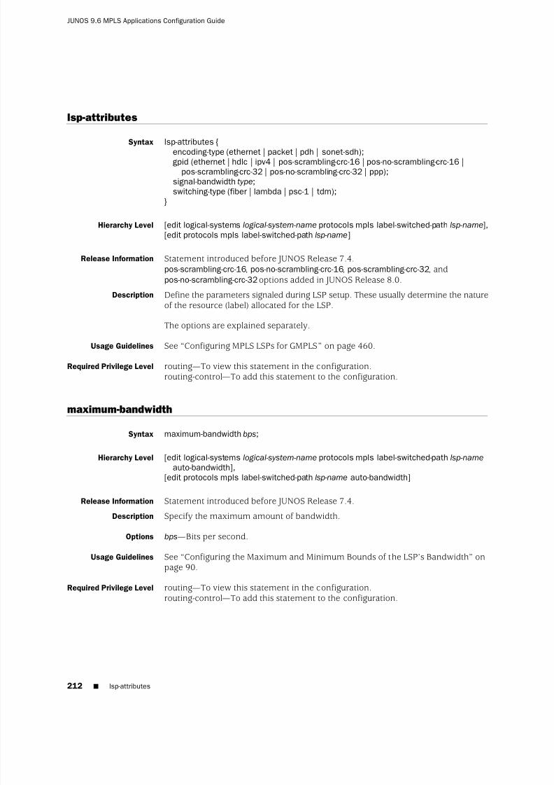
8/7/2019 Config Guide Mpls Applications
http://slidepdf.com/reader/full/config-guide-mpls-applications 250/547
lsp-attributes
Syntax lsp-attributes {encoding-type (ethernet | packet | pdh | sonet-sdh);gpid (ethernet | hdlc | ipv4 | pos-scrambling-crc-16 | pos-no-scrambling-crc-16 |
pos-scrambling-crc-32 | pos-no-scrambling-crc-32 | ppp);signal-bandwidth type;switching-type (fiber | lambda | psc-1 | tdm);
}
Hierarchy Level [edit logical-systems logical-system-name protocols mpls label-switched-path lsp-name],[edit protocols mpls label-switched-path lsp-name]
Release Information Statement introduced before JUNOS Release 7.4.pos-scrambling-crc-16, pos-no-scrambling-crc-16, pos-scrambling-crc-32, andpos-no-scrambling-crc-32options added in JUNOS Release 8.0.
Description Define the parameters signaled during LSP setup. These usually determine the natureof the resource (label) allocated for the LSP.
The options are explained separately.
Usage Guidelines See “Configuring MPLS LSPs for GMPLS” on page 460.
Required Privilege Level routing—To view this statement in the configuration.routing-control—To add this statement to the configuration.
maximum-bandwidth
Syntax maximum-bandwidth bps;
Hierarchy Level [edit logical-systems logical-system-name protocols mpls label-switched-path lsp-name
auto-bandwidth],[edit protocols mpls label-switched-path lsp-name auto-bandwidth]
Release Information Statement introduced before JUNOS Release 7.4.
Description Specify the maximum amount of bandwidth.
Options bps—Bits per second.
Usage Guidelines See “Configuring the Maximum and Minimum Bounds of the LSP’s Bandwidth” onpage 90.
Required Privilege Level routing—To view this statement in the configuration.routing-control—To add this statement to the configuration.
212 ■ lsp-attributes
JUNOS 9.6 MPLS Applications Configuration Guide

8/7/2019 Config Guide Mpls Applications
http://slidepdf.com/reader/full/config-guide-mpls-applications 251/547
metric
Syntax metric metric;
Hierarchy Level [edit logical-systems logical-system-name protocols mpls label-switched-path lsp-name],[edit protocols mpls label-switched-path lsp-name]
Release Information Statement introduced before JUNOS Release 7.4.
Description Compare against another LSP or against an IGP route. To disable dynamic metrictracking, assign a fixed metric value to an LSP. If no metric is assigned, the LSPmetric is dynamic and automatically tracks underlying IGP metrics.
Options metric—LSP metric value.Default: No metric assigned (dynamic)
Range: 1 through 16,777,215Usage Guidelines See “Configuring Static LSP Metrics” on page 82.
Required Privilege Level routing—To view this statement in the configuration.routing-control—To add this statement to the configuration.
minimum-bandwidth
Syntax minimum-bandwidth bps;
Hierarchy Level [edit logical-systems logical-system-name protocols mpls label-switched-path lsp-name
auto-bandwidth],[edit protocols mpls label-switched-path lsp-name auto-bandwidth]
Release Information Statement introduced before JUNOS Release 7.4.
Description Set the minimum bandwidth for an LSP with automatic bandwidth allocation enabled.
Options bps—Bits per second.
Usage Guidelines See “Configuring the Maximum and Minimum Bounds of the LSP’s Bandwidth” onpage 90.
Required Privilege Level routing—To view this statement in the configuration.routing-control—To add this statement to the configuration.
metric ■ 213
Chapter 10: Summary of MPLS Configuration Statements

8/7/2019 Config Guide Mpls Applications
http://slidepdf.com/reader/full/config-guide-mpls-applications 252/547
monitor-bandwidth
Syntax monitor-bandwidth;
Hierarchy Level [edit logical-systems logical-system-name protocols mpls label-switched-path lsp-name
auto-bandwidth],[edit protocols mpls label-switched-path lsp-name auto-bandwidth]
Release Information Statement introduced before JUNOS Release 7.4.
Description Do not automatically adjust bandwidth allocation. However, the maximum averagebandwidth utilization is monitored on the LSP, and the information is recorded inthe MPLS statistics file.
Usage Guidelines See “Configuring Passive Bandwidth Utilization Monitoring” on page 93.
Required Privilege Level routing—To view this statement in the configuration.routing-control—To add this statement to the configuration.
most-fill
See random
mpls
Syntax mpls { ... }
Hierarchy Level [edit logical-systems logical-system-name protocols],[edit protocols]
Release Information Statement introduced before JUNOS Release 7.4.
Description Enable MPLS on the router.
Usage Guidelines See “Minimum MPLS Configuration” on page 51.
Required Privilege Level routing—To view this statement in the configuration.routing-control—To add this statement to the configuration.
214 ■ monitor-bandwidth
JUNOS 9.6 MPLS Applications Configuration Guide
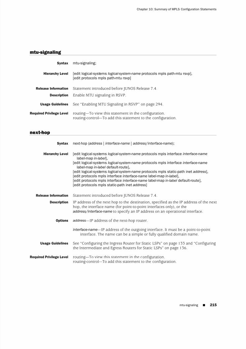
8/7/2019 Config Guide Mpls Applications
http://slidepdf.com/reader/full/config-guide-mpls-applications 253/547
mtu-signaling
Syntax mtu-signaling;
Hierarchy Level [edit logical-systems logical-system-name protocols mpls path-mtu rsvp],[edit protocols mpls path-mtu rsvp]
Release Information Statement introduced before JUNOS Release 7.4.
Description Enable MTU signaling in RSVP.
Usage Guidelines See “Enabling MTU Signaling in RSVP” on page 294.
Required Privilege Level routing—To view this statement in the configuration.routing-control—To add this statement to the configuration.
next-hop
Syntax next-hop (address | interface-name | address /interface-name);
Hierarchy Level [edit logical-systems logical-system-name protocols mpls interface interface-name
label-map in-label],[edit logical-systems logical-system-name protocols mpls interface interface-name
label-map in-label default-route],[edit logical-systems logical-system-name protocols mpls static-path inet address],[edit protocols mpls interface interface-name label-map in-label],[edit protocols mpls interface interface-name label-map in-label default-route],[edit protocols mpls static-path inet address]
Release Information Statement introduced before JUNOS Release 7.4.
Description IP address of the next hop to the destination, specified as the IP address of the nexthop, the interface name (for point-to-point interfaces only), or theaddress/interface-name to specify an IP address on an operational interface.
Options address—IP address of the next-hop router.
interface-name—IP address of the outgoing interface. It must be a point-to-pointinterface. The name can be a simple or fully qualified domain name.
Usage Guidelines See“
Configuring the Ingress Router for Static LSPs”
on page 133 and“
Configuringthe Intermediate and Egress Routers for Static LSPs” on page 136.
Required Privilege Level routing—To view this statement in the configuration.routing-control—To add this statement to the configuration.
mtu-signaling ■ 215
Chapter 10: Summary of MPLS Configuration Statements

8/7/2019 Config Guide Mpls Applications
http://slidepdf.com/reader/full/config-guide-mpls-applications 254/547
no-cspf
Syntax no-cspf;
Hierarchy Level [edit logical-systems logical-system-name protocols mpls],[edit logical-systems logical-system-name protocols mplslabel-switched-path lsp-name],[edit logical-systems logical-system-name protocols mpls label-switched-path lsp-name
(primary | secondary) path-name],[edit protocols mpls],[edit protocols mpls label-switched-path lsp-name],[edit protocols mpls label-switched-path lsp-name (primary | secondary) path-name]
Release Information Statement introduced before JUNOS Release 7.4.
Description Disable constrained-path LSP computation.
An explicit-path LSP is completely configured through operator action. Onceconfigured, it is initiated only along the explicitly specified path.
A constrained-path LSP relies on an ingress router to compute the complete path.The ingress router takes into account the following information during thecomputation:
■ Interior gateway protocol (IGP) topology database
■ Link utilization information from extensions in the IGP link-state database
■ Administrative group information from extensions in the IGP link-state database
■ LSP requirements, including bandwidth, hop count, and administrative group
Constrained-path LSPs can generally avoid link failures and congested links. Theyalso permit recomputation (therefore, a new path) during topology changes orunsuccessful setup.
Default Constrained-path LSP computation enabled.
Usage Guidelines See “Disabling Constrained-Path LSP Computation” on page 95 and “ConfiguringExplicit-Path LSPs” on page 140.
Required Privilege Level routing—To view this statement in the configuration.routing-control—To add this statement to the configuration.
216 ■ no-cspf
JUNOS 9.6 MPLS Applications Configuration Guide

8/7/2019 Config Guide Mpls Applications
http://slidepdf.com/reader/full/config-guide-mpls-applications 255/547
no-decrement-ttl
Syntax no-decrement-ttl;
Hierarchy Level [edit logical-systems logical-system-name protocols mpls],[edit logical-systems logical-system-name protocols mpls label-switched-path lsp-name],[edit logical-systems logical-system-name protocols mpls label-switched-path lsp-name
(primary | secondary) path-name],[edit protocols mpls],[edit protocols mpls label-switched-path lsp-name],[edit protocols mpls label-switched-path lsp-name (primary | secondary) path-name]
Release Information Statement introduced before JUNOS Release 7.4.
Description Disable normal TTL decrementing, which decrements the TTL field in the IP header
by 1. This statement decrements the IP TTL by 1 before encapsulating the IP packetwithin an MPLS packet. When the penultimate router pops off the top label, it doesnot use the standard write-back procedure of writing the MPLS TTL into the IP TTLfield. Therefore, the IP packet is decremented by 1. The ultimate router thendecrements the packet by one more for a total cloud appearance of 2, thus hidingthe network topology.
Default Normal TTL decrementing enabled; the TTL field value is decremented by 1 as thepacket passes through each label-switched router in the LSP.
Usage Guidelines See “Disabling Normal TTL Decrementing” on page 86.
Required Privilege Level routing—To view this statement in the configuration.
routing-control—
To add this statement to the configuration.Related Topics no-propagate-ttl
no-exclude
See exclude
no-include-all
See include-all
no-include-any
See include-any
no-decrement-ttl ■ 217
Chapter 10: Summary of MPLS Configuration Statements

8/7/2019 Config Guide Mpls Applications
http://slidepdf.com/reader/full/config-guide-mpls-applications 256/547
no-install-to-address
Syntax no-install-to-address;
Hierarchy Level [edit logical-systems logical-system-name protocols mpls label-switched-path lsp-name],[edit protocols mpls label-switched-path lsp-name]
Release Information Statement introduced in JUNOS Release 7.4.
Description Prevent the egress router address configured using the to statement from beinginstalled into the inet.3 and inet.0 routing tables.
Default The egress router address for an LSP is installed into the inet.3 and inet.0 routingtables.
Usage Guidelines See “Preventing the Addition of Egress Router Addresses to Routing Tables” on page74.
Required Privilege Level routing—To view this statement in the configuration.routing-control—To add this statement to the configuration.
Related Topics to
no-propagate-ttl
Syntax no-propagate-ttl;
Hierarchy Level [edit logical-systems logical-system-name protocols mpls],[edit protocols mpls]
Release Information Statement introduced before JUNOS Release 7.4.
Description Disable normal TTL decrementing. You configure this statement once per router,and it affects all RSVP-signaled or LDP-signaled LSPs. When this router acts as aningress router for an LSP, it pushes an MPLS header with a TTL value of 255,regardless of the IP packet TTL. When the router acts as the penultimate router, itpops the MPLS header without writing the MPLS TTL into the IP packet.
Default Normal TTL decrementing enabled; the TTL field value is decremented by 1 as thepacket passes through each label-switched router in the LSP.
Usage Guidelines See “Disabling Normal TTL Decrementing” on page 86.
Required Privilege Level routing—To view this statement in the configuration.routing-control—To add this statement to the configuration.
Related Topics no-decrement-ttl
218 ■ no-install-to-address
JUNOS 9.6 MPLS Applications Configuration Guide

8/7/2019 Config Guide Mpls Applications
http://slidepdf.com/reader/full/config-guide-mpls-applications 257/547
no-record
See record
no-trap
Syntax no-trap {mpls-lsp-traps;rfc-3812-traps;
}
Hierarchy Level [edit logical-systems logical-system-name protocols mpls log-updown],[edit protocols mpls log-updown]
Release Information Statement introduced before JUNOS Release 7.4.The mpls-lsp-traps and rfc-3812-traps options added in JUNOS Release 9.0.
Description Prevents the transmission of SNMP traps.
Options mpls-lsp-traps—Blocks the MPLS LSP traps defined in the jnx-mpls.mib, but allows therfc3812.mib traps.
rfc-3812-traps—Blocks the traps defined in the rfc3812.mib, but allows the MPLS LSPtraps defined in the jnx-mpls.mib.
Usage Guidelines See “Configuring System Log Messages and SNMP Traps for LSPs” on page 157 andthe JUNOS Network Management Configuration Guide .
Required Privilege Level routing—To view this statement in the configuration.routing-control—To add this statement to the configuration.
Related Topics traceoptions
no-record ■ 219
Chapter 10: Summary of MPLS Configuration Statements

8/7/2019 Config Guide Mpls Applications
http://slidepdf.com/reader/full/config-guide-mpls-applications 258/547
oam
Syntax oam {bfd-liveness-detection{
failure-action teardown;minimum-interval milliseconds;minimum-receive-interval milliseconds;minimum-transmit-interval milliseconds;multiplier detection-time-multiplier ;
}lsp-ping-interval seconds;
}
Hierarchy Level [edit protocols mpls],[edit protocols mpls label-switched-path lsp-name]
[edit protocols mpls label-switched-path lsp-name primary path-name]
Release Information Statement introduced in JUNOS Release 7.6. The lsp-ping-intervaloption was introducedin JUNOS Release 9.4.
Description Enable Operation, Administration, and Maintenance (OAM) for RSVP-signaled LSPs.
Options lsp-ping-interval seconds—Specify the duration of the LSP ping interval in seconds.To issue a ping on an RSVP-signaled LSP, use the ping mpls rsvp command.
The remaining statements are explained separately.
Usage Guidelines See “Configuring BFD for MPLS IPv4 LSPs” on page 167.
Required Privilege Level routing—To view this statement in the configuration.routing-control—To add this statement to the configuration.
220 ■ oam
JUNOS 9.6 MPLS Applications Configuration Guide

8/7/2019 Config Guide Mpls Applications
http://slidepdf.com/reader/full/config-guide-mpls-applications 259/547
optimize-aggressive
Syntax optimize-aggressive;
Hierarchy Level [edit logical-systems logical-system-name protocols mpls],[edit protocols mpls]
Release Information Statement introduced before JUNOS Release 7.4.
Description If enabled, the LSP reoptimization is based solely on the IGP metric. Thereoptimization process ignores the available bandwidth ratio calculations, the least-fill10 percent congestion improvement rule, and the hop-counts rule. This statementmakes reoptimization more aggressive than the default.
Default Aggressive optimization is disabled.
Usage Guidelines See “Optimizing Signaled LSPs” on page 103.
Required Privilege Level routing—To view this statement in the configuration.routing-control—To add this statement to the configuration.
optimize-aggressive ■ 221
Chapter 10: Summary of MPLS Configuration Statements

8/7/2019 Config Guide Mpls Applications
http://slidepdf.com/reader/full/config-guide-mpls-applications 260/547
optimize-timer
Syntax optimize-timer seconds;
Hierarchy Level [edit logical-systems logical-system-name protocols mpls],[edit logical-systems logical-system-name protocols mpls label-switched-path lsp-name],[edit logical-systems logical-system-name protocols mpls label-switched-path lsp-name
(primary | secondary) path-name],[edit protocols mpls],[edit protocols mpls label-switched-path lsp-name],[edit protocols mpls label-switched-path lsp-name (primary | secondary) path-name]
Release Information Statement introduced before JUNOS Release 7.4.
Description Enable periodic reoptimization of an LSP that is already set up. If topology changes
occur, an existing path might become suboptimal, and a subsequent recomputationmight be able to determine a better path. This option is useful only on LSPs for whichconstrained-path computation is enabled; that is, for which the no-cspf statement isnot configured.
To avoid extensive resource consumption that might result because of frequent pathrecomputations, or to avoid destabilizing the network as a result of constantlychanging LSPs, we recommend that you either leave the timer value sufficiently largeor disable the timer value.
Default The optimize timer is disabled.
Options seconds—Length of the optimize timer, in seconds.
Range: 0 through 65,535 secondsDefault: 0 seconds (the optimize timer is disabled)
Usage Guidelines See “Optimizing Signaled LSPs” on page 103.
Required Privilege Level routing—To view this statement in the configuration.routing-control—To add this statement to the configuration.
222 ■ optimize-timer
JUNOS 9.6 MPLS Applications Configuration Guide

8/7/2019 Config Guide Mpls Applications
http://slidepdf.com/reader/full/config-guide-mpls-applications 261/547
p2mp
Syntax p2mp p2mp-lsp-name;
Hierarchy Level [edit logical-systems logical-system-name protocols mpls label-switched-path lsp-name],[edit protocols mpls label-switched-path lsp-name]
Release Information Statement introduced before JUNOS Release 7.4.
Description Specify an LSP as either a point-to-multipoint LSP or as a branch LSP of apoint-to-multipoint LSP by specifying the point-to-multipoint LSP path name.
Options p2mp-lsp-name—Name of the point-to-multipoint LSP path that identifies the sequenceof nodes that form the point-to-multipoint LSP. The name can contain up to 32characters and can include letters, digits, periods, and hyphens. To include other
characters or use a longer name, enclose the name in quotation marks. Thename must be unique within the ingress router.
Usage Guidelines See “Configuring the Primary Point-to-Multipoint LSP” on page 141.
Required Privilege Level routing—To view this statement in the configuration.routing-control—To add this statement to the configuration.
p2mp-lsp-next-hop
Syntax p2mp-lsp-next-hop point-to-multipoint-lsp-next-hop;
Hierarchy Level [edit logical-systems logical-system-name routing-options static route route-name],[edit routing-options static route route-name]
Release Information Statement introduced before JUNOS Release 7.4.
Description Specify the name of the point-to-multipoint LSP to be used as a next hop for thestatic route.
Options point-to-multipoint-lsp-next-hop—Name of the point-to-multipoint LSP.
Usage Guidelines See “Configuring Static Unicast Routes for Point-to-Multipoint LSPs” on page 138.
Required Privilege Level routing—To view this statement in the configuration.
routing-control—
To add this statement to the configuration.
p2mp ■ 223
Chapter 10: Summary of MPLS Configuration Statements

8/7/2019 Config Guide Mpls Applications
http://slidepdf.com/reader/full/config-guide-mpls-applications 262/547
path
Syntax path path-name {(address | hostname) <strict | loose>;
}
Hierarchy Level [edit logical-systems logical-system-name protocols mpls],[edit protocols mpls]
Release Information Statement introduced before JUNOS Release 7.4.
Description Create a named path and optionally specify the sequence of explicit routers thatform the path.
You must include this statement when configuring explicit LSPs.
Options address—(Optional) IP address of each transit router in the LSP. You must specifythe address or hostname of each transit router, although you do not need to listeach transit router if its type is loose. As an option, you can include the ingressand egress routers in the path. Specify the addresses in order, starting with theingress router (optional) or the first transit router, and continuing sequentiallyalong the path until reaching the egress router (optional) or the router immediatelybefore the egress router.Default: If you do not specify any routers explicitly, no routing limitations areimposed on the LSP.
hostname—(Optional) See address.Default: If you do not specify any routers explicitly, no routing limitations are
imposed on the LSP.
loose—(Optional) Indicate that the next address in the path statement is a loose link.This means that the LSP can traverse through other routers before reaching thisrouter.Default: strict
path-name—Name that identifies the sequence of nodes that form an LSP. The namecan contain up to 32 characters and can include letters, digits, periods, andhyphens. To include other characters or use a longer name, enclose the namein quotation marks. The name must be unique within the ingress router.
strict—(Optional) Indicate that the LSP must go to the next address specified in thepath statement without traversing other nodes. This is the default.
Usage Guidelines See “Creating Named Paths” on page 52.
Required Privilege Level routing—To view this statement in the configuration.routing-control—To add this statement to the configuration.
Related Topics static-path
224 ■ path
JUNOS 9.6 MPLS Applications Configuration Guide
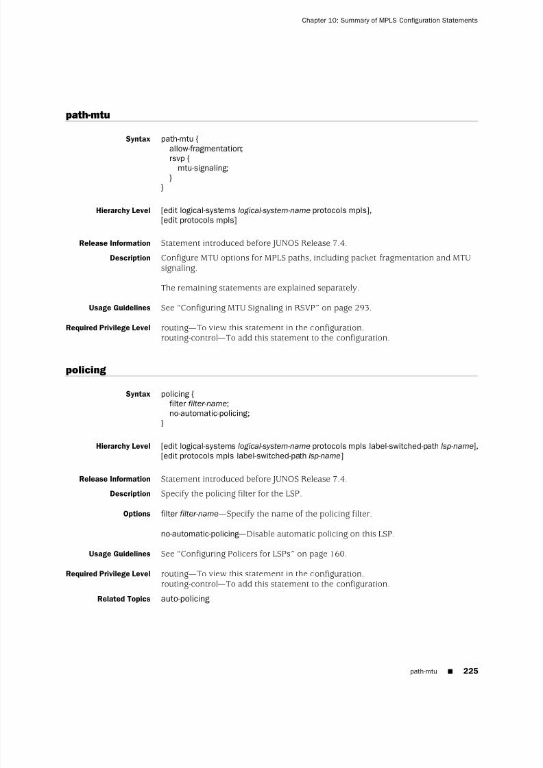
8/7/2019 Config Guide Mpls Applications
http://slidepdf.com/reader/full/config-guide-mpls-applications 263/547
path-mtu
Syntax path-mtu {allow-fragmentation;rsvp {
mtu-signaling;}
}
Hierarchy Level [edit logical-systems logical-system-name protocols mpls],[edit protocols mpls]
Release Information Statement introduced before JUNOS Release 7.4.
Description Configure MTU options for MPLS paths, including packet fragmentation and MTU
signaling.
The remaining statements are explained separately.
Usage Guidelines See “Configuring MTU Signaling in RSVP” on page 293.
Required Privilege Level routing—To view this statement in the configuration.routing-control—To add this statement to the configuration.
policing
Syntax policing {
filter filter-name;no-automatic-policing;
}
Hierarchy Level [edit logical-systems logical-system-name protocols mpls label-switched-path lsp-name],[edit protocols mpls label-switched-path lsp-name]
Release Information Statement introduced before JUNOS Release 7.4.
Description Specify the policing filter for the LSP.
Options filter filter-name—Specify the name of the policing filter.
no-automatic-policing—
Disable automatic policing on this LSP.Usage Guidelines See “Configuring Policers for LSPs” on page 160.
Required Privilege Level routing—To view this statement in the configuration.routing-control—To add this statement to the configuration.
Related Topics auto-policing
path-mtu ■ 225
Chapter 10: Summary of MPLS Configuration Statements

8/7/2019 Config Guide Mpls Applications
http://slidepdf.com/reader/full/config-guide-mpls-applications 264/547
pop
Syntax pop;
Hierarchy Level [edit logical-systems logical-system-name protocols mpls interface interface-name
label-map (in-label | default-route)],[edit protocols mpls interface interface-name label-map (in-label | default-route)]
Release Information Statement introduced before JUNOS Release 7.4.
Description Remove the label from the top of the label stack. If there is another label in the stack,that label becomes the label at the top of the label stack. Otherwise, the packet isforwarded as a native protocol packet (typically, as an IP packet).
Usage Guidelines See “Configuring the Intermediate and Egress Routers for Static LSPs” on page 136.
Required Privilege Level routing—To view this statement in the configuration.routing-control—To add this statement to the configuration.
Related Topics swap
226 ■ pop
JUNOS 9.6 MPLS Applications Configuration Guide
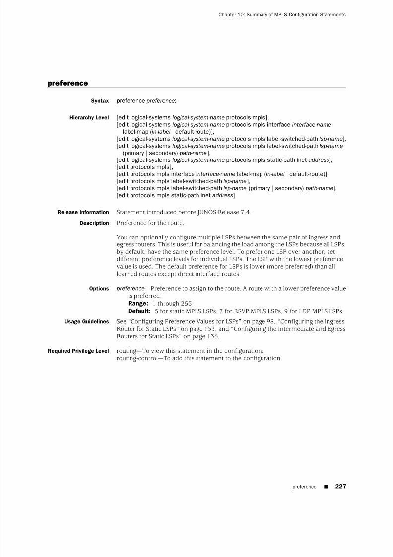
8/7/2019 Config Guide Mpls Applications
http://slidepdf.com/reader/full/config-guide-mpls-applications 265/547

8/7/2019 Config Guide Mpls Applications
http://slidepdf.com/reader/full/config-guide-mpls-applications 266/547
primary
Syntax primary path-name {adaptive;admin-group {
exclude [ group-names ];include-all [ group-names ];include-any [ group-names ];
}bandwidth bps;class-of-service cos-value;hop-limit number ;no-cspf ;no-decrement-ttl;optimize-timer seconds;
preference preference;priority setup-priority reservation-priority ;(record | no-record);select (manual | unconditional);standby;
}
Hierarchy Level [edit logical-systems logical-system-name protocols mpls label-switched-path lsp-name],[edit protocols mpls label-switched-path lsp-name]
Release Information Statement introduced before JUNOS Release 7.4.
Description Specify the primary path to use for an LSP. You can configure only one primary path.
You can optionally specify preference, CoS, and bandwidth values for the primarypath, which override any equivalent values that you configure for the LSP (at the [editmpls label-switched-path lsp-name] hierarchy level).
Options path-name—Name of a path that you created with the path statement.
The remaining statements are explained separately.
Usage Guidelines See “Configuring Primary and Secondary LSPs” on page 75.
Required Privilege Level routing—To view this statement in the configuration.routing-control—To add this statement to the configuration.
228 ■ primary
JUNOS 9.6 MPLS Applications Configuration Guide

8/7/2019 Config Guide Mpls Applications
http://slidepdf.com/reader/full/config-guide-mpls-applications 267/547
priority
Syntax priority setup-priority reservation-priority ;
Hierarchy Level [edit logical-systems logical-system-name protocols mpls],[edit logical-systems logical-system-name protocols mpls label-switched-path lsp-name],[edit logical-systems logical-system-name protocols mpls label-switched-path lsp-name
(primary | secondary) path-name],[edit protocols mpls],[edit protocols mpls label-switched-path lsp-name],[edit protocols mpls label-switched-path lsp-name (primary | secondary) path-name]
Release Information Statement introduced before JUNOS Release 7.4.
Description Configure the setup priority and reservation priority for an LSP. If insufficient link
bandwidth is available during session establishment, the setup priority is comparedwith other setup priorities for established sessions on the link to determine whethersome of them should be preempted to accommodate the new session. Sessions withlower hold priorities are preempted.
Options reservation-priority —Reservation priority, used to keep a reservation after it has beenset up. A smaller number has a higher priority. The priority must be greater thanor equal to the setup priority to prevent preemption loops.Range: 0 through 7, where 0 is the highest and 7 is the lowest priority.Default: 0 (Once the session is set up, no other session can preempt it.)
setup-priority —Setup priority.Range: 0 through 7, where 0 is the highest and 7 is the lowest priority.
Default: 7 (The session cannot preempt any existing sessions.)Usage Guidelines See “Configuring Priority and Preemption for LSPs” on page 102.
Required Privilege Level routing—To view this statement in the configuration.routing-control—To add this statement to the configuration.
priority ■ 229
Chapter 10: Summary of MPLS Configuration Statements

8/7/2019 Config Guide Mpls Applications
http://slidepdf.com/reader/full/config-guide-mpls-applications 268/547
push
Syntax push out-label;
Hierarchy Level [edit logical-systems logical-system-name protocols mpls static-path inet address],[edit protocols mpls static-path inet address]
Release Information Statement introduced before JUNOS Release 7.4.
Description Add a new label to the top of the label stack.
Options out-label—Label value.Range: 0 through 1,048,575. Labels 0 through 999,999 are for internal use.Labels 1,000,000 through 1,048,575 are unassigned by the JUNOS Software andare available for static LSPs. When you configure static LSPs, you can use only
this range of labels.Usage Guidelines See “Configuring the Ingress Router for Static LSPs” on page 133.
Required Privilege Level routing—To view this statement in the configuration.routing-control—To add this statement to the configuration.
230 ■ push
JUNOS 9.6 MPLS Applications Configuration Guide

8/7/2019 Config Guide Mpls Applications
http://slidepdf.com/reader/full/config-guide-mpls-applications 269/547
random
Syntax (random | least-fill | most-fill);
Hierarchy Level [edit logical-systems logical-system-name protocols mpls label-switched-path lsp-name],[edit protocols mpls label-switched-path lsp-name]
Release Information Statement introduced before JUNOS Release 7.4.
Description Configure the preferred path when several equal-cost candidate paths to a destinationexist, and prefer the path with the highest available bandwidth (with the largestminimum available bandwidth ratio). The available bandwidth ratio of a link is theavailable bandwidth on a link divided by the maximum reservable bandwidth on thelink.
■
least-fill—
Prefer the path with the most available bandwidth (with the largestminimum available bandwidth ratio).
■ most-fill—Prefer the path with the least available bandwidth (with the minimumavailable bandwidth ratio). The minimum available bandwidth ratio of a path isthe smallest available bandwidth ratio belonging to any of the links in the path.
■ random—Choose the path at random.
Default random
Usage Guidelines See “Configuring CSPF Tie Breaking” on page 83.
Required Privilege Level routing—To view this statement in the configuration.
routing-control—
To add this statement to the configuration.
random ■ 231
Chapter 10: Summary of MPLS Configuration Statements

8/7/2019 Config Guide Mpls Applications
http://slidepdf.com/reader/full/config-guide-mpls-applications 270/547
record
Syntax (record | no-record);
Hierarchy Level [edit logical-systems logical-system-name protocols mpls],[edit logical-systems logical-system-name protocols mpls label-switched-path lsp-name],[edit logical-systems logical-system-name protocols mpls label-switched-path (primary |
secondary) path-name],[edit protocols mpls],[edit protocols mpls label-switched-path lsp-name],[edit protocols mpls label-switched-path lsp-name (primary | secondary) path-name]
Release Information Statement introduced before JUNOS Release 7.4.
Description Specify whether an LSP should actively record the routes in the path. Recording
routes requires that all transit routers support the RSVP Record Route object.Recording routes can be useful for diagnostics and loop detection.
Default Record routes.
Usage Guidelines See “Disabling Path Route Recording” on page 98.
Required Privilege Level routing—To view this statement in the configuration.routing-control—To add this statement to the configuration.
reject
Syntax reject;
Hierarchy Level [edit logical-systems logical-system-name protocols mpls interface interface-name
label-map (in-label | default-route)],[edit protocols mpls interface interface-name label-map (in-label | default-route)]
Release Information Statement introduced before JUNOS Release 7.4.
Description Do not forward a packet with the matching incoming label. Instead, drop the packetand, for IP packets, send an ICMP unreachable message to the packet’s originator.
Usage Guidelines See “Configuring the Intermediate and Egress Routers for Static LSPs” on page 136.
Required Privilege Level routing—
To view this statement in the configuration.routing-control—To add this statement to the configuration.
232 ■ record
JUNOS 9.6 MPLS Applications Configuration Guide

8/7/2019 Config Guide Mpls Applications
http://slidepdf.com/reader/full/config-guide-mpls-applications 271/547
retry-limit
Syntax retry-limit number ;
Hierarchy Level [edit logical-systems logical-system-name protocols mpls label-switched-path lsp-name],[edit protocols mpls label-switched-path lsp-name],
Release Information Statement introduced before JUNOS Release 7.4.
Description Maximum number of times the ingress router tries to establish the primary path.This counter is reset each time a primary path is created successfully. When the limitis exceeded, no more connection attempts are made. Intervention is then requiredto restart the connection.
Options number —Maximum number of tries to establish the primary path.
Range: 0 through 10,000Default: 0 (The ingress node never stops trying to establish the primary path.)
Usage Guidelines See “Configuring the Connection Between Ingress and Egress Routers” on page 81.
Required Privilege Level routing—To view this statement in the configuration.routing-control—To add this statement to the configuration.
retry-timer
Syntax retry-timer seconds;
Hierarchy Level [edit logical-systems logical-system-name protocols mpls label-switched-path lsp-name],[edit protocols mpls label-switched-path lsp-name]
Release Information Statement introduced before JUNOS Release 7.4.
Description Amount of time the ingress router waits between attempts to establish the primarypath.
Options seconds—Amount of time between attempts to connect to the primary path.Range: 1 through 600 secondsDefault: 30 seconds
Usage Guidelines See “Configuring the Connection Between Ingress and Egress Routers” on page 81.
Required Privilege Level routing—To view this statement in the configuration.routing-control—To add this statement to the configuration.
retry-limit ■ 233
Chapter 10: Summary of MPLS Configuration Statements

8/7/2019 Config Guide Mpls Applications
http://slidepdf.com/reader/full/config-guide-mpls-applications 272/547
revert-timer
Syntax revert-timer seconds;
Hierarchy Level [edit logical-systems logical-system-name protocols mpls],[edit logical-systems logical-system-name protocols mpls label-switched-path lsp-name],[edit protocols mpls],[edit protocols mpls label-switched-path lsp-name]
Release Information Statement introduced before JUNOS Release 7.4.BFD behavior modified in JUNOS Release 9.0.
Description Specify the amount of time (in seconds) that an LSP must wait before traffic revertsto a primary path. If during this time the primary path experiences any connectivityproblem or stability problem, the timer is restarted.
If you have configured BFD on the LSP, the JUNOS Software waits until the BFDsession is restored before starting the revert timer counter.
If you have configured a value of 0 seconds for the revert-timer statement and trafficis switched to the secondary path, the traffic remains on that path indefinitely. It isnever switched back to the primary path unless you intervene.
Options seconds—Time in seconds.Range: 0 through 65,535 secondsDefault: 60 seconds
Usage Guidelines See “Configuring the Revert Timer for LSPs” on page 76.
Required Privilege Level routing—To view this statement in the configuration.routing-control—To add this statement to the configuration.
234 ■ revert-timer
JUNOS 9.6 MPLS Applications Configuration Guide

8/7/2019 Config Guide Mpls Applications
http://slidepdf.com/reader/full/config-guide-mpls-applications 273/547
rpf-check-policy
Syntax rpf-check-policy policy ;
Hierarchy Level [edit logical-systems logical-system-name routing-options multicast],[edit routing-options multicast]
Release Information Statement introduced in JUNOS Release 8.0.
Description Allows you to control whether an reverse path forwarding (RPF) check is performedfor a source and group entry before installing a route in the multicast forwardingcache. This makes it possible to use point-to-multipoint LSPs to distribute multicasttraffic to PIM islands situated downstream from the egress routers of thepoint-to-multipoint LSPs.
Options policy —Name of the RPF check routing policy.
Usage Guidelines See “Configuring a Multicast RPF Check Policy for Point-to-Multipoint LSPs” on page145.
Required Privilege Level routing—To view this statement in the configuration.routing-control—To add this statement to the configuration.
rpf-check-policy ■ 235
Chapter 10: Summary of MPLS Configuration Statements

8/7/2019 Config Guide Mpls Applications
http://slidepdf.com/reader/full/config-guide-mpls-applications 274/547
rsvp-error-hold-time
Syntax rsvp-error-hold-time seconds;
Hierarchy Level [edit logical-systems logical-system-name protocols mpls],[edit protocols mpls]
Release Information Statement introduced before JUNOS Release 7.4.
Description Amount of time MPLS retains RSVP PathErr messages and considers them for CSPFcomputations. The more time you configure, the more time a source node (ingressof an RSVP LSP) can have to learn about the failures of its LSP by monitoring PathErrmessages transmitted from downstream nodes.
Information from the PathErr messages is incorporated into subsequent LSP
computations, which can improve the accuracy and speed of LSP setup. Some PathErrmessages are also used to update traffic engineering database bandwidth information,reducing inconsistencies between the database and the network.
Options seconds—Amount of time MPLS retains RSVP PathErr messages and considers themfor CSPF computations.Range: 0 through 240 secondsDefault: 25 seconds
Usage Guidelines See “Improving Traffic Engineering Database Accuracy with RSVP PathErr Messages”on page 60.
Required Privilege Level routing—To view this statement in the configuration.routing-control—To add this statement to the configuration.
236 ■ rsvp-error-hold-time
JUNOS 9.6 MPLS Applications Configuration Guide

8/7/2019 Config Guide Mpls Applications
http://slidepdf.com/reader/full/config-guide-mpls-applications 275/547
secondary
Syntax secondary path-name {adaptive;admin-group {
exclude [ group-names ];include-all [ group-names ];include-any [ group-names ];
}bandwidth bps;class-of-service cos-value;hop-limit number ;no-cspf ;no-decrement-ttl;optimize-timer seconds;
preference preference;priority setup-priority reservation-priority ;(record | no-record);retry-limit number ;retry-timer seconds;select (manual | unconditional);standby;
}
Hierarchy Level [edit logical-systems logical-system-name protocols mpls label-switched-path lsp-name],[edit protocols mpls label-switched-path lsp-name]
Release Information Statement introduced before JUNOS Release 7.4.
Description Specify one or more secondary paths to use for the LSP. You can configure morethan one secondary path. All secondary paths are equal, and the first one that isavailable is chosen.
You can specify secondary paths even if you have not specified any primary paths.
Optionally, you can specify preference, CoS, and bandwidth values for the secondarypath, which override any equivalent values that you configure for the LSP (at the [editmpls label-switched-path] hierarchy level).
Options path-name—Name of a path that you created with the path statement.
The remaining statements are explained separately.
Usage Guidelines See “Configuring Primary and Secondary LSPs” on page 75.
Required Privilege Level routing—To view this statement in the configuration.routing-control—To add this statement to the configuration.
secondary ■ 237
Chapter 10: Summary of MPLS Configuration Statements

8/7/2019 Config Guide Mpls Applications
http://slidepdf.com/reader/full/config-guide-mpls-applications 276/547
select
Syntax select (manual | unconditional);
Hierarchy Level [edit logical-systems logical-system-name protocols mpls label-switched-path lsp-name
(primary | secondary) path-name],[edit protocols mpls label-switched-path lsp-name (primary | secondary) path-name]
Release Information Statement introduced before JUNOS Release 7.4.
Description Specify the conditions under which the path is selected to carry traffic. The manualand unconditional options are mutually exclusive.
Options manual—The path is selected for carrying traffic if it is up and stable for at least therevert timer window (potentially before the revert timer has elapsed). Traffic is
sent to other working paths if the current path is down or degraded (receivingerrors).
unconditional—The path is always selected for carrying traffic, even if it is currentlydown or degraded (receiving errors).
Usage Guidelines See “Specifying the Conditions for Path Selection” on page 77.
Required Privilege Level routing—To view this statement in the configuration.routing-control—To add this statement to the configuration.
signal-bandwidth
Syntax signal-bandwidth type;
Hierarchy Level [edit logical-systems logical-system-name protocols mpls label-switched-path lsp-name
lsp-attributes],[edit protocols mpls label-switched-path lsp-name lsp-attributes]
Release Information Statement introduced before JUNOS Release 7.4.
Description Specify the bandwidth encoding of the signal used for path computation andadmission control.
Options type—Configure the type of bandwidth encoding used on the LSP. It can be any of
the following values: 10gigether, ds1, ds3, e1, e3, ethernet, fastether, gigether,stm-1, stm-4, stm-16, stm-64, stm-256, sts-1, vt1-5, or vt2.
Usage Guidelines See “Configuring the Signal Bandwidth Type” on page 461.
Required Privilege Level routing—To view this statement in the configuration.routing-control—To add this statement to the configuration.
238 ■ select
JUNOS 9.6 MPLS Applications Configuration Guide

8/7/2019 Config Guide Mpls Applications
http://slidepdf.com/reader/full/config-guide-mpls-applications 277/547
smart-optimize-timer
Syntax smart-optimize-timer seconds;
Hierarchy Level [edit logical-systems logical-system-name protocols mpls],[edit protocols mpls]
Release Information Statement introduced before JUNOS Release 7.4.
Description When a link fails and traffic is moved to an alternate path, the smart optimize timerwaits for the specified period of time and then switches the traffic back to the originalpath (if that path is back up). If the original path fails again, the traffic is shifted toan alternate path and the smart optimization timer is disabled for one hour. Thisstatement is disabled by default.
Options seconds—Specify the number of seconds for the smart optimize timer.Range: 0 through 65,535 secondsDefault: 180 seconds
Usage Guidelines See “Configuring the Smart Optimize Timer” on page 105.
Required Privilege Level routing—To view this statement in the configuration.routing-control—To add this statement to the configuration.
soft-preemption
Syntax soft-preemption;
Hierarchy Level [edit logical-systems logical-system-name protocols mpls label-switched-path lsp-name],[edit protocols mpls label-switched-path lsp-name]
Release Information Statement introduced before JUNOS Release 7.4.
Description Soft preemption attempts to establish a new path for a preempted LSP before tearingit down.
Usage Guidelines See “Configuring MPLS Soft Preemption” on page 87.
Required Privilege Level routing—To view this statement in the configuration.routing-control—To add this statement to the configuration.
smart-optimize-timer ■ 239
Chapter 10: Summary of MPLS Configuration Statements

8/7/2019 Config Guide Mpls Applications
http://slidepdf.com/reader/full/config-guide-mpls-applications 278/547
standby
Syntax standby;
Hierarchy Level [edit logical-systems logical-system-name protocols mpls],[edit logical-systems logical-system-name protocols mpls label-switched-path lsp-name],[edit logical-systems logical-system-name protocols mpls label-switched-path lsp-name
(primary | secondary) path-name],[edit protocols mpls],[edit protocols mpls label-switched-path lsp-name],[edit protocols mpls label-switched-path lsp-name (primary | secondary) path-name]
Release Information Statement introduced before JUNOS Release 7.4.
Description Have the path remain up at all times to provide instant switchover if connectivity
problems occur.
Usage Guidelines See “Configuring Hot Standby of Secondary Paths” on page 106.
Required Privilege Level routing—To view this statement in the configuration.routing-control—To add this statement to the configuration.
240 ■ standby
JUNOS 9.6 MPLS Applications Configuration Guide

8/7/2019 Config Guide Mpls Applications
http://slidepdf.com/reader/full/config-guide-mpls-applications 279/547
static-path
Syntax static-path inet {prefix {
class-of-service cos-value;double-push bottom-label top-label;next-hop (address | interface-name | address /interface-name);preference preference;push out-label;triple-push bottom-label middle-label top-label;
}}
Hierarchy Level [edit logical-systems logical-system-name protocols mpls],[edit protocols mpls]
Release Information Statement introduced before JUNOS Release 7.4.
Description Statically configure an LSP. You configure the LSP on the ingress router only.
You can specify one or more static-path statements.
Options prefix—IP address that matches the packet’s destination field. You can specify oneor more addresses. You can specify the prefix in one of the following ways:
■ IP address; for example, 10.0.0.2
■ Range of IP addresses; for example, 10.0.0.0/8
inet—Configure the path for packets with IPv4 destinations.
The remaining statements are explained separately.
Usage Guidelines See “Configuring the Ingress Router for Static LSPs” on page 133.
Required Privilege Level routing—To view this statement in the configuration.routing-control—To add this statement to the configuration.
static-path ■ 241
Chapter 10: Summary of MPLS Configuration Statements
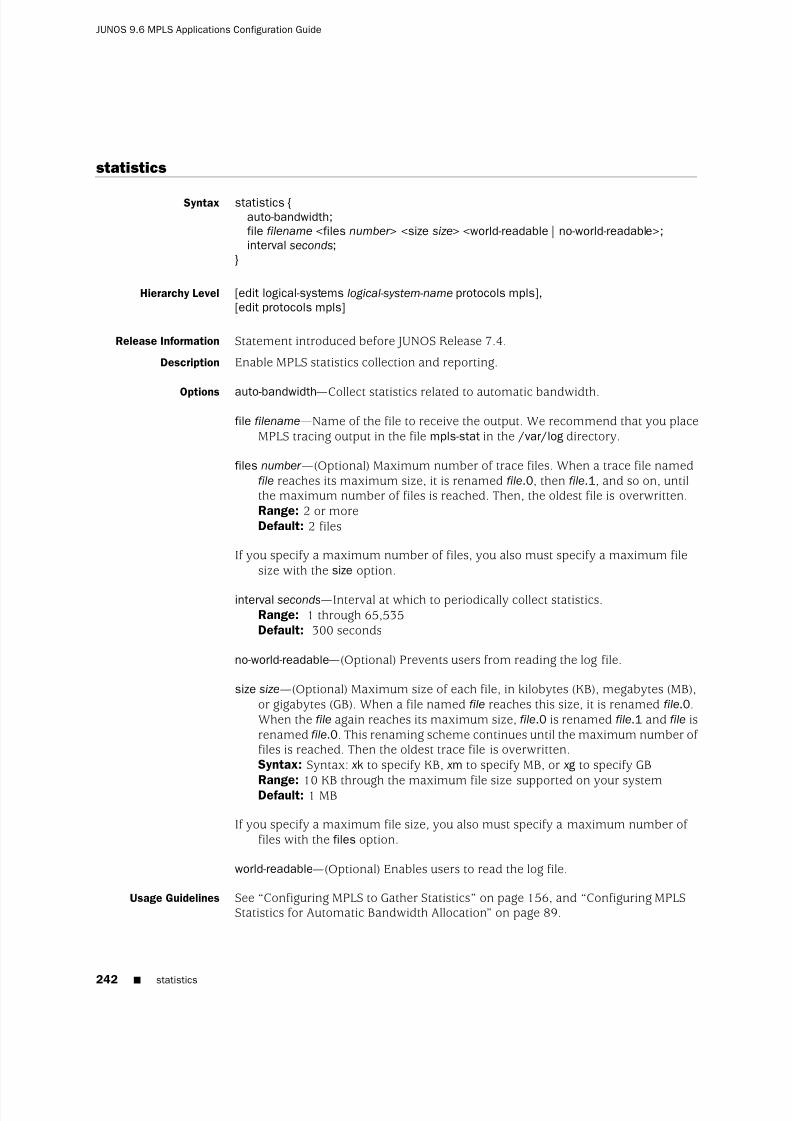
8/7/2019 Config Guide Mpls Applications
http://slidepdf.com/reader/full/config-guide-mpls-applications 280/547
statistics
Syntax statistics {auto-bandwidth;file filename <files number > <size size> <world-readable | no-world-readable>;interval seconds;
}
Hierarchy Level [edit logical-systems logical-system-name protocols mpls],[edit protocols mpls]
Release Information Statement introduced before JUNOS Release 7.4.
Description Enable MPLS statistics collection and reporting.
Options auto-bandwidth—Collect statistics related to automatic bandwidth.
file filename—Name of the file to receive the output. We recommend that you placeMPLS tracing output in the file mpls-stat in the /var/log directory.
files number —(Optional) Maximum number of trace files. When a trace file namedfile reaches its maximum size, it is renamed file.0, then file.1, and so on, untilthe maximum number of files is reached. Then, the oldest file is overwritten.Range: 2 or moreDefault: 2 files
If you specify a maximum number of files, you also must specify a maximum filesize with the size option.
interval seconds—Interval at which to periodically collect statistics.Range: 1 through 65,535Default: 300 seconds
no-world-readable—(Optional) Prevents users from reading the log file.
size size—(Optional) Maximum size of each file, in kilobytes (KB), megabytes (MB),or gigabytes (GB). When a file named file reaches this size, it is renamed file.0.When the file again reaches its maximum size, file.0 is renamed file.1 and file isrenamed file.0. This renaming scheme continues until the maximum number of files is reached. Then the oldest trace file is overwritten.Syntax: Syntax: xk to specify KB, xm to specify MB, or xg to specify GB
Range: 10 KB through the maximum file size supported on your systemDefault: 1 MB
If you specify a maximum file size, you also must specify a maximum number of files with the files option.
world-readable—(Optional) Enables users to read the log file.
Usage Guidelines See “Configuring MPLS to Gather Statistics” on page 156, and “Configuring MPLSStatistics for Automatic Bandwidth Allocation” on page 89.
242 ■ statistics
JUNOS 9.6 MPLS Applications Configuration Guide

8/7/2019 Config Guide Mpls Applications
http://slidepdf.com/reader/full/config-guide-mpls-applications 281/547
Required Privilege Level routing and trace—To view this statement in the configuration.routing-control and trace-control—To add this statement to the configuration.
swap
Syntax swap out-label;
Hierarchy Level [edit logical-systems logical-system-name protocols mpls interface interface-name
label-map (in-label | default-route)],[edit protocols mpls interface interface-name label-map (in-label | default-route)]
Release Information Statement introduced before JUNOS Release 7.4.
Description Remove the label at the top of the label stack and replace it with the specified label.
Options out-label—Label value.
Range: 0 through 1,048,575. Labels 0 through 999,999 are for internal use.Labels 1,000,000 through 1,048,575 are unassigned by the JUNOS Software andare available for static LSPs. When you configure static LSPs, you can use onlythis range of labels.Default: If you do not define the out-label option, the original label value remainsunchanged.
Usage Guidelines See “Configuring the Intermediate and Egress Routers for Static LSPs” on page 136.
Required Privilege Level routing—To view this statement in the configuration.routing-control—To add this statement to the configuration.
Related Topics pop
swap ■ 243
Chapter 10: Summary of MPLS Configuration Statements

8/7/2019 Config Guide Mpls Applications
http://slidepdf.com/reader/full/config-guide-mpls-applications 282/547
swap-push
Syntax swap-push swap-label push-label ;
Hierarchy Level [edit logical-systems logical-system-name protocols mpls interface interface-name
label-map in-label | default-route)],[edit protocols mpls interface interface-name label-map in-label | default-route)]
Release Information Statement introduced before JUNOS Release 7.4.
Description Replace the stack’s top label and then push one more label on top of the stack.
Options push-label—Label value.
swap-label—Label value.
The following range and default values apply to both push-label and swap-label:Range: 0 through 1,048,575. Labels 0 through 999,999 are for internal use.Labels 1,000,000 through 1,048,575 are unassigned by the JUNOS Software andare available for static LSPs. When you configure static LSPs, you can use onlythis range of labels.Default: If you do not define the swap-label option, the original label valueremains unchanged.
Usage Guidelines See “Configuring the Intermediate and Egress Routers for Static LSPs” on page 136.
Required Privilege Level routing—To view this statement in the configuration.routing-control—To add this statement to the configuration.
Related Topics pop and swap
244 ■ swap-push
JUNOS 9.6 MPLS Applications Configuration Guide

8/7/2019 Config Guide Mpls Applications
http://slidepdf.com/reader/full/config-guide-mpls-applications 283/547
switching-type
Syntax switching-type (fiber | lambda | psc-1 | tdm);
Hierarchy Level [edit logical-systems logical-system-name protocols mpls label-switched-path lsp-name
lsp-attributes],[edit protocols mpls label-switched-path lsp-name lsp-attributes]
Release Information Statement introduced before JUNOS Release 7.4.
Description Specify the switching method for the LSP. The switching method can be one of thefollowing values:
■ fiber—Fiber switching
■ lambda—Lambda switching
■ psc-1—Packet switching
■ tdm—Time-division multiplexing (TDM) switching
Default psc-1
Usage Guidelines See “Configuring MPLS LSPs for GMPLS” on page 460.
Required Privilege Level routing—To view this statement in the configuration.routing-control—To add this statement to the configuration.
switching-type ■ 245
Chapter 10: Summary of MPLS Configuration Statements

8/7/2019 Config Guide Mpls Applications
http://slidepdf.com/reader/full/config-guide-mpls-applications 284/547
te-class-matrix
Syntax te-class-matrix {tenumber {
priority priority ;traffic-class {
ctnumber priority priority ;}
}}
Hierarchy Level [edit logical-systems logical-system-name protocols mpls diffserv-te],[edit protocols mpls diffserv-te]
Release Information Statement introduced before JUNOS Release 7.4.
Description Specify the traffic engineering class matrix for a multiclass LSP or a DiffServ-awaretraffic engineering LSP.
Default The default traffic engineering class matrix is:
te-class-matrix {te0 traffic-class ct0 priority 7;te1 traffic-class ct1 priority 7;te2 traffic-class ct2 priority 7;te3 traffic-class ct3 priority 7;te4 traffic-class ct0 priority 0;te5 traffic-class ct1 priority 0;te6 traffic-class ct2 priority 0;
te7 traffic-class ct3 priority 0;}
If you define any of the traffic engineering classes, all the default values are dropped.
Options ctnumber —Specify the number of the class type. It can be one of four values: ct0,ct1, ct2, or ct3.
priority priority —Specify the priority of the class type. It can be one of eight valuesfrom 0 through 7.
tenumber —Specify the number of the traffic engineering class. It can be one of eightvalues: te0, te1, te2, te3, te4, te5, te6, or te7. You must configure the traffic
engineering classes in order, starting with te0.traffic-class—Specify the traffic class for the traffic engineering class.
Usage Guidelines See “Configuring Traffic Engineering Classes” on page 117.
Required Privilege Level routing—To view this statement in the configuration.routing-control—To add this statement to the configuration.
246 ■ te-class-matrix
JUNOS 9.6 MPLS Applications Configuration Guide

8/7/2019 Config Guide Mpls Applications
http://slidepdf.com/reader/full/config-guide-mpls-applications 285/547
to
Syntax to address;
Hierarchy Level [edit logical-systems logical-system-name protocols mpls label-switched-path lsp-name],[edit protocols mpls label-switched-path lsp-name]
Release Information Statement introduced before JUNOS Release 7.4.
Description Specify the egress router of a dynamic LSP.
Options address—Address of the egress router.
Usage Guidelines See “Configuring the Egress Router Address for LSPs” on page 74.
Required Privilege Level routing—To view this statement in the configuration.routing-control—To add this statement to the configuration.
to ■ 247
Chapter 10: Summary of MPLS Configuration Statements

8/7/2019 Config Guide Mpls Applications
http://slidepdf.com/reader/full/config-guide-mpls-applications 286/547
traceoptions
Syntax traceoptions {file filename <files number > <size size> <world-readable | no-world-readable>;flag flag ;
}
Hierarchy Level [edit logical-systems logical-system-name protocols mpls],[edit logical-systems logical-system-name protocols mpls label-switched-path lsp-name],[edit protocols mpls],[edit protocols mpls label-switched-path lsp-name]
Release Information Statement introduced before JUNOS Release 7.4.
Description Configure MPLS tracing options at the protocol level or for a label-switched path.
To specify more than one tracing operation, include multiple flag statements.
Default The default MPLS protocol-level tracing options are inherited from the routingprotocols traceoptions statement included at the [edit routing-options] hierarchy level.
Options filename—Name of the file to receive the output of the tracing operation. All files areplaced in the directory /var/log. We recommend that you place MPLS tracingoutput in the file mpls-log.
files number —(Optional) Maximum number of trace files. When a trace file namedtrace-file reaches its maximum size, it is renamed trace-file.0, then trace-file.1,and so on, until the maximum number of trace files is reached. Then the oldest
trace file is overwritten.Range: 2 through 1000Default: 2 files
If you specify a maximum number of files, you must also include the size statementto specify the maximum file size.
flag —Tracing operation to perform. To specify more than one tracing operation,include multiple flag statements.
MPLS Tracing Flags
■ all—Trace all operations
■ connection—All circuit cross-connect (CCC) activity
■ connection-detail—Detailed CCC activity
■ cspf —CSPF computations
■ cspf-link—Links visited during CSPF computations
■ cspf-node—Nodes visited during CSPF computations
■ error—MPLS error packets
■ graceful-restart—Trace MPLS graceful restart events
248 ■ traceoptions
JUNOS 9.6 MPLS Applications Configuration Guide

8/7/2019 Config Guide Mpls Applications
http://slidepdf.com/reader/full/config-guide-mpls-applications 287/547
■ lsping—Trace lsping packets and return codes
■ state—All LSP state transitions
■ timer—Timer usage
no-world-readable—(Optional) Allow only certain users to read the log file.
size size—(Optional) Maximum size of each trace file, in kilobytes (KB), megabytes(MB), or gigabytes (GB). When a trace file named trace-file reaches this size, it isrenamed trace-file.0. When the trace-file again reaches this size, trace-file.0 isrenamed trace-file.1 and trace-file is renamed trace-file.0. This renaming schemecontinues until the maximum number of trace files is reached. Then the oldesttrace file is overwritten.Syntax: xk to specify KB, xm to specify MB, or xg to specify GBRange: 10 KB through the maximum file size supported on your systemDefault: 1 MB
If you specify a maximum file size, you must also include the files statement tospecify the maximum number of files.
world-readable—(Optional) Allow any user to read the log file.
Usage Guidelines See “Tracing MPLS and LSP Packets and Operations” on page 171.
Required Privilege Level routing and trace—To view this statement in the configuration.routing-control and trace-control—To add this statement to the configuration.
traceoptions ■ 249
Chapter 10: Summary of MPLS Configuration Statements

8/7/2019 Config Guide Mpls Applications
http://slidepdf.com/reader/full/config-guide-mpls-applications 288/547
traffic-engineering
Syntax traffic-engineering (bgp | bgp-igp | bgp-igp-both-ribs | mpls-forwarding);
Hierarchy Level [edit logical-systems logical-system-name protocols mpls],[edit protocols mpls]
Release Information Statement introduced before JUNOS Release 7.4.
Description Select whether MPLS performs traffic engineering on BGP destinations only or onboth BGP and IGP destinations. Affects only LSPs originating from this router, nottransit or egress LSPs.
Default bgp
Options bgp—On BGP destinations only. Ingress routes are installed in the inet.3 routing table.
bgp-igp—On both BGP and IGP destinations. Ingress routes are installed in the inet.0routing table. If IGP shortcuts are enabled, the shortcut routes are automaticallyinstalled in the inet.0 routing table.
bgp-igp-both-ribs—On both BGP and IGP destinations. Ingress routes are installed inthe inet.0 and inet.3 routing tables. This option is used to support VPNs.
mpls-forwarding—On both BGP and IGP destinations. Use ingress routes for forwardingonly, not for routing.
Usage Guidelines See “Configuring Traffic Engineering for LSPs” on page 150.
Required Privilege Level routing—To view this statement in the configuration.routing-control—To add this statement to the configuration.
250 ■ traffic-engineering
JUNOS 9.6 MPLS Applications Configuration Guide

8/7/2019 Config Guide Mpls Applications
http://slidepdf.com/reader/full/config-guide-mpls-applications 289/547
triple-push
Syntax triple-push <bottom-label> <middle-label> <top-label>;
Hierarchy Level [edit logical-systems logical-system-name protocols mpls static-path inet prefix],[edit protocols mpls static-path inet prefix]
Release Information Statement introduced before JUNOS Release 7.4.
Description Push three more labels on top of the stack.
Options bottom-label—(Optional) Label value.
middle-label—(Optional) Label value.
top-label—(Optional) Label value.
The labels all have the same range and default actions:Range: 0 through 1,048,575. Labels 0 through 999,999 are for internal use.Labels 1,000,000 through 1,048,575 are unassigned by the JUNOS Software andare available for static LSPs. When you configure static LSPs, you can use onlythis range of labels.Default: If you do not define the push-label option, the original label valueremains unchanged.
Usage Guidelines See “Configuring the Ingress Router for Static LSPs” on page 133.
Required Privilege Level routing—To view this statement in the configuration.routing-control—To add this statement to the configuration.
triple-push ■ 251
Chapter 10: Summary of MPLS Configuration Statements

8/7/2019 Config Guide Mpls Applications
http://slidepdf.com/reader/full/config-guide-mpls-applications 290/547

8/7/2019 Config Guide Mpls Applications
http://slidepdf.com/reader/full/config-guide-mpls-applications 291/547
Part 3
RSVP
■ RSVP Overview on page 255
■ RSVP Configuration Guidelines on page 273
■ Summary of RSVP Configuration Statements on page 299
RSVP ■ 253

8/7/2019 Config Guide Mpls Applications
http://slidepdf.com/reader/full/config-guide-mpls-applications 292/547
254 ■ RSVP
JUNOS 9.6 MPLS Applications Configuration Guide

8/7/2019 Config Guide Mpls Applications
http://slidepdf.com/reader/full/config-guide-mpls-applications 293/547
Chapter 11
RSVP Overview
This chapter discusses the following topics:
■ RSVP Introduction on page 256
■ RSVP Standards on page 256
■ JUNOS Software RSVP Protocol Implementation on page 257
■ RSVP Operation on page 258
■ RSVP Operation Overview on page 258
■ RSVP Authentication on page 259
■ RSVP and IGP Hello Packets and Timers on page 259
■ RSVP Message Types on page 259
■ Path Messages on page 260
■ Resv Messages on page 260
■ PathTear Messages on page 260
■ ResvTear Messages on page 260
■ PathErr Messages on page 261
■ ResvErr Messages on page 261
■ ResvConfirm Messages on page 261
■ RSVP Reservation Styles on page 261
■ RSVP Refresh Reduction on page 262
■ MTU Signaling in RSVP on page 263
■ How the Correct MTU Is Signaled in RSVP on page 264
■ Determining an Outgoing MTU Value on page 265
■ MTU Signaling in RSVP Limitations on page 265
■ Link Protection on page 265■ Fast Reroute, Node Protection, and Link Protection on page 266
■ Multiple Bypass LSPs on page 267
■ Node Protection on page 267
■ RSVP Graceful Restart on page 268
■ RSVP Graceful Restart Standard on page 269
■ RSVP Graceful Restart Terminology on page 269
■ 255

8/7/2019 Config Guide Mpls Applications
http://slidepdf.com/reader/full/config-guide-mpls-applications 294/547
■ RSVP Graceful Restart Operation on page 270
■ Processing the Restart Cap Object on page 271
RSVP Introduction
RSVP is a resource reservation setup protocol that is used by both network hosts androuters. Hosts use RSVP to request a specific class of service (CoS) from the networkfor particular application flows. Routers use RSVP to deliver CoS requests to all routersalong the data path. RSVP also can maintain and refresh states for a requested CoSapplication flow.
RSVP treats an application flow as a simplex connection. That is, the CoS requesttravels only in one direction—from the sender to the receiver. RSVP is a transportlayer protocol that uses IP as its network layer. However, RSVP does not transportapplication flows. Rather, it is more of an Internet control protocol, similar to theInternet Control Message Protocol (ICMP) and Internet Group Management Protocol
(IGMP). RSVP runs as a separate software process in the JUNOS Software and is notin the packet forwarding path.
RSVP is not a routing protocol, but rather is designed to operate with current andfuture unicast and multicast routing protocols. The routing protocols are responsiblefor choosing the routes to use to forward packets, and RSVP consults local routingtables to obtain routes. RSVP only ensures the CoS of packets traveling along a datapath.
The receiver in an application flow requests the preferred CoS from the sender. Todo this, the receiver issues an RSVP CoS request on behalf of the local application.The request propagates to all routers in reverse direction of the data paths towardthe sender. In this process, RSVP requests might be merged, resulting in a protocolthat scales well when there are a large number of receivers.
Because the number of receivers in an application flow is likely to change and theflow of delivery paths might change during the life of an application flow, RSVP takesa soft-state approach in its design, creating and removing the protocol states inrouters and hosts incrementally over time. RSVP sends periodic refresh messagesto maintain its state and to recover from occasional lost messages. In the absenceof refresh messages, RSVP states automatically time out and are deleted.
RSVP Standards
RSVP is described in several RFCs and drafts.
The following RFCs provide an overview of RSVP and RSVP features:■ RFC 2205, Resource Reservation Protocol (RSVP), Version 1, Functional Specification
■ RFC 2209, Resource Reservation Protocol (RSVP), Version 1, Message Processing Rules
■ RFC 2210, The Use of RSVP with IETF Integrated Services
■ RFC 2211, Specification of the Controlled-Load Network Element Service
■ RFC 2212, Specification of Guaranteed Quality of Service
256 ■ RSVP Introduction
JUNOS 9.6 MPLS Applications Configuration Guide

8/7/2019 Config Guide Mpls Applications
http://slidepdf.com/reader/full/config-guide-mpls-applications 295/547

8/7/2019 Config Guide Mpls Applications
http://slidepdf.com/reader/full/config-guide-mpls-applications 296/547
The primary purpose of the JUNOS RSVP software is to support dynamic signalingwithin MPLS label-switched paths (LSPs). Supporting resource reservations over theInternet is only a secondary purpose of the JUNOS Software implementation. Sincesupporting resource reservations is secondary, the JUNOS RSVP software does not
support the following features:■ IP multicasting sessions.
■ Traffic control. The software cannot make resource reservations for real-timevideo or audio sessions.
With regard to the protocol mechanism, packet processing, and RSVP objectssupported, the JUNOS Software implementation of the software is interoperable withother RSVP implementations.
RSVP Operation
The following sections describe RSVP operation:■ RSVP Operation Overview on page 258
■ RSVP Authentication on page 259
■ RSVP and IGP Hello Packets and Timers on page 259
RSVP Operation Overview
RSVP creates independent sessions to handle each data flow. A session is identifiedby a combination of the destination address, an optional destination port, and aprotocol. Within a session, there can be one or more senders. Each sender is identified
by a combination of its source address and source port. An out-of-band mechanism,such as a session announcement protocol or human communication, is used tocommunicate the session identifier to all senders and receivers.
A typical RSVP session involves the following sequence of events:
1. A potential sender starts sending RSVP path messages to the session address.
2. A receiver, wanting to join the session, registers itself if necessary. For example,a receiver in a multicast application would register itself with IGMP.
3. The receiver receives the path messages.
4. The receiver sends appropriate Resv messages toward the sender. These messagescarry a flow descriptor, which is used by routers along the path to makereservations in their link-layer media.
5. The sender receives the Resv message and then starts sending application data.
This sequence of events is not necessarily strictly synchronized. For example, receiverscan register themselves before receiving path messages from the sender, andapplication data can flow before the sender receives Resv messages. Application datathat is delivered before the actual reservation contained in the Resv message typicallyis treated as best-effort, non-real-time traffic with no CoS guarantee.
258 ■ RSVP Operation
JUNOS 9.6 MPLS Applications Configuration Guide

8/7/2019 Config Guide Mpls Applications
http://slidepdf.com/reader/full/config-guide-mpls-applications 297/547
RSVP Authentication
JUNOS Software supports both the RSVP authentication style described in RFC 2747(allowing for multivendor compatibility) and the RSVP authentication style describedin Internet draft draft-ietf-rsvp-md5-03.txt. The JUNOS Software uses theauthentication style described in Internet draft draft-ietf-rsvp-md5-08.txt by default.If the router receives an RFC 2747-style RSVP authentication from a neighbor, itswitches to this style of authentication for that neighbor. The RSVP authenticationstyle for each neighboring router is determined separately.
RSVP and IGP Hello Packets and Timers
RSVP monitors the status of the interior gateway protocol (IGP) (IS-IS or OSPF)neighbors and relies on the IGP protocols to detect when a node fails. If an IGPprotocol declares a neighbor down (because hello packets are no longer beingreceived), RSVP also brings down that neighbor. However, the IGP protocols andRSVP still act independently when bringing a neighbor up.
In JUNOS Software, RSVP typically relies on IGP hello packet detection to check fornode failures. RSVP sessions are kept up even if RSVP hello packets are no longerbeing received, so long as the router continues to receive IGP hello packets. RSVPsessions are maintained until either the router stops receiving IGP hello packets orthe RSVP Path and Resv messages time out. Configuring a short time for the IS-IS orOSPF hello timers allows these protocols to detect node failures quickly.
RSVP hellos can be relied on when the IGP does not recognize a particular neighbor(for example, if IGP is not enabled on the interface) or if the IGP is RIP (not IS-IS orOSPF). Also, the equipment of other vendors might be configured to monitor RSVP
sessions based on RSVP hello packets. This equipment might also take an RSVPsession down due to a loss of RSVP hello packets.
Juniper Networks does not recommend configuring a short RSVP hello timer. If quickdiscovery of a failed neighbor is needed, configure short IGP (OSPF or IS-IS) hellotimers.
OSPF and IS-IS have infrastructure to manage rapid hello message sending andreceiving reliably, even if the routing protocols or some other process are strainingthe processing capability of the router. Under the same circumstances, RSVP hellosmight timeout prematurely even though the neighbor is functioning normally.
RSVP Message Types
RSVP uses the following types of messages to establish and remove paths for dataflows, establish and remove reservation information, confirm the establishment of reservations, and report errors:
■ Path Messages on page 260
■ Resv Messages on page 260
■ PathTear Messages on page 260
RSVP Authentication ■ 259
Chapter 11: RSVP Overview
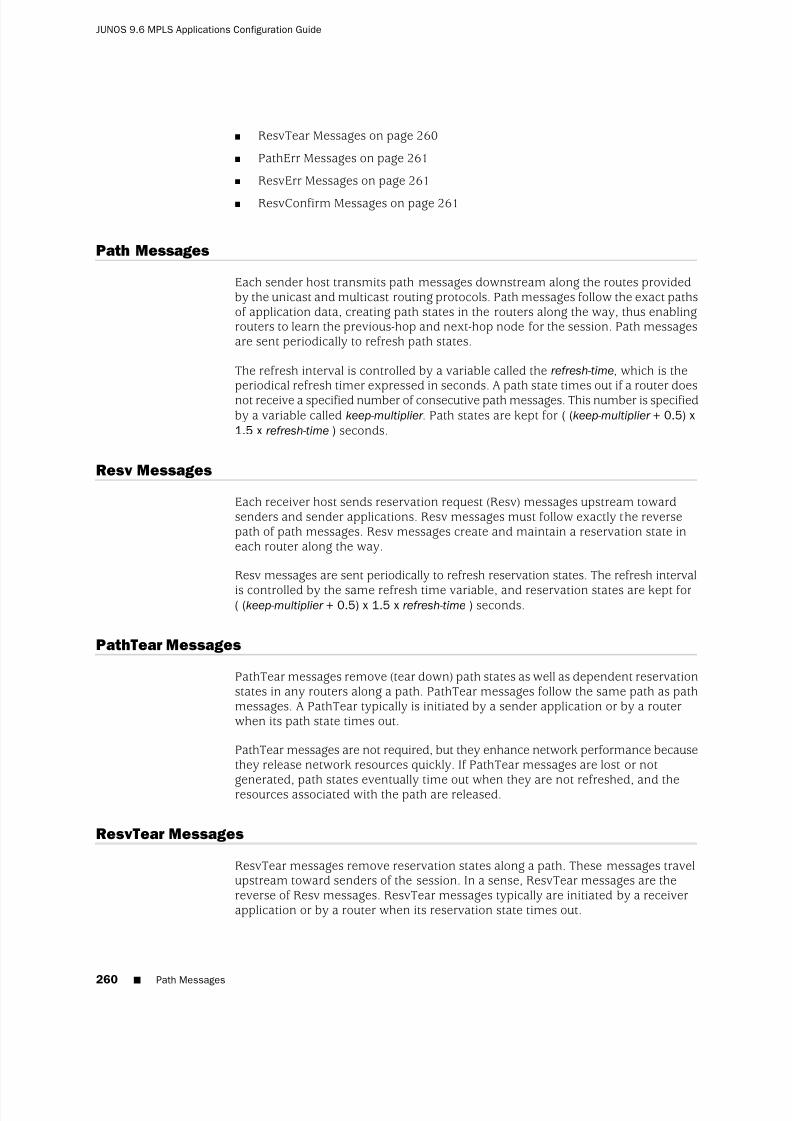
8/7/2019 Config Guide Mpls Applications
http://slidepdf.com/reader/full/config-guide-mpls-applications 298/547
■ ResvTear Messages on page 260
■ PathErr Messages on page 261
■ ResvErr Messages on page 261
■ ResvConfirm Messages on page 261
Path Messages
Each sender host transmits path messages downstream along the routes providedby the unicast and multicast routing protocols. Path messages follow the exact pathsof application data, creating path states in the routers along the way, thus enablingrouters to learn the previous-hop and next-hop node for the session. Path messagesare sent periodically to refresh path states.
The refresh interval is controlled by a variable called the refresh-time, which is theperiodical refresh timer expressed in seconds. A path state times out if a router doesnot receive a specified number of consecutive path messages. This number is specifiedby a variable called keep-multiplier . Path states are kept for ( (keep-multiplier + 0.5) x1.5 x refresh-time ) seconds.
Resv Messages
Each receiver host sends reservation request (Resv) messages upstream towardsenders and sender applications. Resv messages must follow exactly the reversepath of path messages. Resv messages create and maintain a reservation state ineach router along the way.
Resv messages are sent periodically to refresh reservation states. The refresh interval
is controlled by the same refresh time variable, and reservation states are kept for( (keep-multiplier + 0.5) x 1.5 x refresh-time ) seconds.
PathTear Messages
PathTear messages remove (tear down) path states as well as dependent reservationstates in any routers along a path. PathTear messages follow the same path as pathmessages. A PathTear typically is initiated by a sender application or by a routerwhen its path state times out.
PathTear messages are not required, but they enhance network performance becausethey release network resources quickly. If PathTear messages are lost or not
generated, path states eventually time out when they are not refreshed, and theresources associated with the path are released.
ResvTear Messages
ResvTear messages remove reservation states along a path. These messages travelupstream toward senders of the session. In a sense, ResvTear messages are thereverse of Resv messages. ResvTear messages typically are initiated by a receiverapplication or by a router when its reservation state times out.
260 ■ Path Messages
JUNOS 9.6 MPLS Applications Configuration Guide

8/7/2019 Config Guide Mpls Applications
http://slidepdf.com/reader/full/config-guide-mpls-applications 299/547
ResvTear messages are not required, but they enhance network performance becausethey release network resources quickly. If ResvTear messages are lost or notgenerated, reservation states eventually time out when they are not refreshed, andthe resources associated with the reservation are released.
PathErr Messages
When path errors occur (usually because of parameter problems in a path message),the router sends a unicast PathErr message to the sender that issued the pathmessage. PathErr messages are advisory; these messages do not alter any path statealong the way.
ResvErr Messages
When a reservation request fails, a ResvErr error message is delivered to all thereceivers involved. ResvErr messages are advisory; these messages do not alter anyreservation state along the way.
ResvConfirm Messages
Receivers can request confirmation of a reservation request, and this confirmationis sent with a ResvConfirm message. Because of the complex RSVP flow-mergingrules, a confirmation message does not necessarily provide end-to-end confirmationof the entire path. Therefore, ResvConfirm messages are an indication, not aguarantee, of potential success.
Juniper Networks routers never request confirmation using the ResvConfirm message;however, a Juniper Networks router can send a ResvConfirm message if it receives
a request from another vendor's equipment.
RSVP Reservation Styles
A reservation request includes options for specifying the reservation style. Thereservation styles define how reservations for different senders within the samesession are treated and how senders are selected.
Two options specify how reservations for different senders within the same sessionare treated:
■ Distinct reservation—Each receiver establishes its own reservation with eachupstream sender.
■ Shared reservation—All receivers make a single reservation that is shared amongmany senders.
Two options specify how senders are selected:
■ Explicit sender—List all selected senders.
■ Wildcard sender—Select all senders, which then participate in the session.
PathErr Messages ■ 261
Chapter 11: RSVP Overview

8/7/2019 Config Guide Mpls Applications
http://slidepdf.com/reader/full/config-guide-mpls-applications 300/547
The following reservation styles, formed by a combination of these four options,currently are defined:
■ Fixed filter (FF)—This reservation style consists of distinct reservations amongexplicit senders. Examples of applications that use fixed-filter-style reservationsare video applications and unicast applications, which both require flows thathave a separate reservation for each sender. The fixed filter reservation style isenabled on RSVP LSPs by default.
■ Wildcard filter (WF)—This reservation style consists of shared reservations amongwildcard senders. This type of reservation reserves bandwidth for any and allsenders, and propagates upstream toward all senders, automatically extendingto new senders as they appear. A sample application for wildcard filterreservations is an audio application in which each sender transmits a distinctdata stream. Typically, only a few senders are transmitting at any one time. Sucha flow does not require a separate reservation for each sender; a single reservationis sufficient.
■ Shared explicit (SE)—This reservation style consists of shared reservations among
explicit senders. This type of reservation reserves bandwidth for a limited groupof senders. A sample application is an audio application similar to that describedfor wildcard filter reservations.
RSVP Refresh Reduction
RSVP relies on soft-state to maintain the path and reservation states on each router.If the corresponding refresh messages are not sent periodically, the states eventuallytime out and reservations are deleted. RSVP also sends its control messages as IPdatagrams with no reliability guarantee. It relies on periodic refresh messages tohandle the occasional loss of Path or Resv messages.
The RSVP refresh reduction extensions, based on RFC 2961, addresses the followingproblems that result from relying on periodic refresh messages to handle messageloss:
■ Scalability—The scaling problem arises from the periodic transmission andprocessing overhead of refresh messages, which increases as the number of RSVP sessions increases.
■ Reliability and latency—The reliability and latency problem stems from the lossof nonrefresh RSVP messages or one-time RSVP messages such as PathTear orPathErr. The time to recover from such a loss is usually tied to refresh intervaland the keepalive timer.
The RSVP refresh reduction capability is advertised by enabling the refresh reduction(RR) capable bit in the RSVP common header. This bit is only significant betweenRSVP neighbors.
RSVP refresh reduction includes the following features:
■ RSVP message bundling using the bundle message
■ RSVP Message ID to reduce message processing overhead
262 ■ RSVP Refresh Reduction
JUNOS 9.6 MPLS Applications Configuration Guide

8/7/2019 Config Guide Mpls Applications
http://slidepdf.com/reader/full/config-guide-mpls-applications 301/547
■ Reliable delivery of RSVP messages using Message ID, Message Ack, and MessageNack
■ Summary refresh to reduce the amount of information transmitted every refreshinterval
The RSVP refresh reduction specification (RFC 2961) allows you to enable some orall of the above capabilities on a router. It also describes various procedures that arouter can use to detect the refresh reduction capabilities of its neighbor.
The JUNOS Software supports all of the refresh reduction extensions, some of whichcan be selectively enabled or disabled. The JUNOS Software supports Message IDand therefore can perform reliable message delivery only for Path and Resv messages.
For information on how to configure RSVP refresh reduction, see “Configuring RSVPRefresh Reduction” on page 275.
MTU Signaling in RSVP
The maximum transmission unit (MTU) is the largest size packet or frame, in bytes,that can be sent in a network. An MTU that is too large might cause retransmissions.Too small an MTU might cause the router to send and handle relatively more headeroverhead and acknowledgments. There are default values for MTUs associated withvarious protocols. You can also explicitly configure an MTU on an interface.
When an LSP is created across a set of links with different MTU sizes, the ingressrouter does not know what the smallest MTU is on the LSP path. By default, themaximum packet size for the LSP is based on the MTU for the outgoing interface forthe LSP on the ingress router.
If this MTU is larger than the MTU of one of the intermediate links, traffic might bedropped, because MPLS packets cannot be fragmented. Also, the ingress router isnot aware of this type of traffic loss, because the control plane for the LSP would stillfunction normally.
To prevent this type of packet loss in MPLS LSPs, you can configure MTU signalingin RSVP. This feature is described in RFC 3209. Juniper Networks supports theIntegrated Services object for MTU signaling in RSVP. The Integrated Services objectis described in RFCs 2210 and 2215. MTU signaling in RSVP is disabled by default.
To avoid packet loss due to MTU mismatches, the ingress router needs to do thefollowing:
■ Signal the MTU on the RSVP LSP—To prevent packet loss from an MTU mismatch,
the ingress router needs to know what the smallest MTU value is along the pathtaken by the LSP. Once this MTU value is obtained, the ingress router can assignit to the LSP.
■ Fragment packets—Using the assigned MTU value, packets that exceed the sizeof the MTU can be fragmented into smaller packets on the ingress router beforethey are sent over the RSVP LSP.
MTU Signaling in RSVP ■ 263
Chapter 11: RSVP Overview

8/7/2019 Config Guide Mpls Applications
http://slidepdf.com/reader/full/config-guide-mpls-applications 302/547
Once both MTU signaling and packet fragmentation have been enabled on an ingressrouter, any route resolving to an RSVP LSP on this router uses the signaled MTUvalue. For information on how to configure this feature, see “Configuring MTUSignaling in RSVP” on page 293.
The following sections describe how MTU signaling in RSVP works:
■ How the Correct MTU Is Signaled in RSVP on page 264
■ Determining an Outgoing MTU Value on page 265
■ MTU Signaling in RSVP Limitations on page 265
How the Correct MTU Is Signaled in RSVP
How the correct MTU is signaled in RSVP varies depending on whether the networkdevices (for example, routers) explicitly support MTU signaling in RSVP or not.
If the network devices support MTU signaling in RSVP, the following occur when youenable MTU signaling:
■ The MTU is signaled from the ingress router to the egress router by means of the Adspec object. Before forwarding this object, the ingress router enters theMTU value associated with the interface over which the path message is sent.At each hop in the path, the MTU value in the Adspec object is updated to theminimum of the received value and the value of the outgoing interface.
■ The ingress router uses the traffic specification (Tspec) object to specify theparameters for the traffic it is going to send. The MTU value signaled for theTspec object at the ingress router is the maximum MTU value (9192 bytes). Thisvalue does not change en route to the egress router.
■
When the Adspec object arrives at the egress router, the MTU value is correctfor the path (meaning it is the smallest MTU value discovered). The egress routercompares the MTU value in the Adspec object to the MTU value in the Tspecobject. It signals the smaller MTU using the Flowspec object in the Resv message.
■ When the Resv object arrives at the ingress router, the MTU value in this objectis used as the MTU for the next hops that use the LSP.
In a network where there are devices that do not support MTU signaling in RSVP,you might have the following behaviors:
■ If the egress router does not support MTU signaling in RSVP, the MTU is set tothe value of the outgoing interface on the ingress router. Setting the MTU to thevalue of the outgoing interface is the same as the default behavior when MTU
signaling is not configured.■ A Juniper Networks transit router that does not support MTU signaling in RSVP
always propagates an MTU value of 1500 in the Adspec object.
264 ■ How the Correct MTU Is Signaled in RSVP
JUNOS 9.6 MPLS Applications Configuration Guide

8/7/2019 Config Guide Mpls Applications
http://slidepdf.com/reader/full/config-guide-mpls-applications 303/547
Determining an Outgoing MTU Value
The outgoing MTU value is the smaller of the values received in the Adspec objectcompared to the MTU value of the outgoing interface. The MTU value of the outgoinginterface is determined as follows:
■ If you configure an MTU value under the [family mpls] hierarchy level, this valueis signaled.
■ If you do not configure an MTU, the inet MTU is signaled.
MTU Signaling in RSVP Limitations
The following are limitations to MTU signaling in RSVP:
■ Changes in the MTU value might cause a temporary loss of traffic in the followingsituations:
■ For link protection and node protection, the MTU of the bypass is onlysignaled at the time the bypass becomes active. During the time it takes forthe new path MTU to be propagated, packet loss might occur because of anMTU mismatch.
■ For fast reroute, the MTU of the path is updated only after the detour becomesactive, causing a delay in an update to the MTU at the ingress router. Untilthe MTU is updated, packet loss might occur if there is an MTU mismatch.
In both cases, only packets that are larger than the detour or bypass MTUare lost.
■ When an MTU is updated, it triggers a change in the next hop. Any change inthe next hop causes the route statistics to be lost.
■ The minimum MTU supported for MTU signaling in RSVP is 1488 bytes. Thisvalue prevents a false or incorrectly configured value from being used.
■ For single-hop LSPs, the MTU value displayed by the show commands is theRSVP-signaled value. However, this MPLS value is ignored and the correct IPvalue is used.
Link Protection
Link protection helps to ensure that traffic going over a specific interface to a
neighboring router can continue to reach this router if that interface fails. When linkprotection is configured for an interface and an LSP that traverses this interface, abypass LSP is created that will handle this traffic if the interface fails. The bypass LSPuses a different interface and path to reach the same destination. The path used canbe configured explicitly, or you can rely on CSPF. The RSVP metric for the bypassLSP is set in the range of 20,000 through 29,999 (this value is not user configurable).
If a link-protected interface fails, traffic is quickly switched to the bypass LSP. Notethat a bypass LSP cannot share the same egress interface with the LSPs it monitors.
Determining an Outgoing MTU Value ■ 265
Chapter 11: RSVP Overview

8/7/2019 Config Guide Mpls Applications
http://slidepdf.com/reader/full/config-guide-mpls-applications 304/547
In Figure 21 on page 266, link protection is enabled on Interface B between Router1 and Router 2. It is also enabled on LSP A, an LSP that traverses the link betweenRouter 1 and Router 2. If the link between Router 1 and Router 2 fails, traffic fromLSP A is quickly switched to the bypass LSP generated by link protection.
Figure 21: Link Protection Creating a Bypass LSP for the Protected Interface
Although LSPs traversing an interface can be configured to take advantage of link
protection, it is important to note that it is specifically the interface that benefits fromlink protection. If link protection is enabled on an interface but not on a particularLSP traversing that interface, then if the interface fails, that LSP will also fail.
NOTE: Link protection does not work on unnumbered interfaces.
To protect traffic over the entire route taken by an LSP, you should configure fastreroute. For more information, see “Configuring Fast Reroute” on page 78.
The following sections provide more information on link protection:
■ Fast Reroute, Node Protection, and Link Protection on page 266
■ Multiple Bypass LSPs on page 267
Fast Reroute, Node Protection, and Link Protection
RFC 4090, Fast Reroute Extensions to RSVP-TE for LSP Tunnels, describes two differenttypes of traffic protection for RSVP-signaled LSPs:
■ One-to-one backup—In the JUNOS Software this type of traffic protection isprovided by fast reroute. Each LSP requires a protecting LSP to be signaled ateach hop except the egress router. This protecting LSP cannot be shared.
■ Facility backup—This is sometimes called many-to-one backup. In the JUNOS
Software this type of traffic protection is provided by node and link protection.Each LSP requires a protecting LSP to be signaled at each hop except the egressrouter. Unlike fast reroute, this protecting LSP can be shared by other LSPs.
The information above is summarized in Table 5 on page 267.
266 ■ Fast Reroute, Node Protection, and Link Protection
JUNOS 9.6 MPLS Applications Configuration Guide

8/7/2019 Config Guide Mpls Applications
http://slidepdf.com/reader/full/config-guide-mpls-applications 305/547
Table 5: One-to-One Backup Compared with Facility Backup
Facility BackupOne-to-One BackupComparison
Bypass LSPDetour LSPName of the protecting LSP
Can be shared by multipleLSPs
Cannot be sharedSharing of the protecting LSP
node-link-protection andlink-protection
fast-reroute JUNOS configuration statements
Multiple Bypass LSPs
By default, link protection relies on a single bypass LSP to provide path protectionfor an interface. However, you can also specify multiple bypass LSPs to provide link
protection for an interface. You can individually configure each of these bypass LSPsor create a single configuration for all of the bypass LSPs. If you do not configure thebypass LSPs individually, they all share the same path and bandwidth constraints.
The following algorithm describes how and when an additional bypass LSP is activatedfor an LSP:
1. If any currently active bypass can satisfy the requirements of the LSP (bandwidth,link protection, or node-link protection), the traffic is directed to that bypass.
2. If no active bypass LSP is available, scan through the manual bypass LSPs infirst-in, first-out (FIFO) order, skipping those that are already active (each manualbypass can only be activated once). The first inactive manual bypass that cansatisfy the requirements is activated and traffic is directed to that bypass.
3. If no manual bypass LSPs are available and if the max-bypasses statementactivates multiple bypass LSPs for link protection, determine whether anautomatically configured bypass LSP can satisfy the requirements. If anautomatically configured bypass LSP is available and if the total number of activeautomatically configured bypass LSPs does not exceed the maximum bypassLSP limit (configured with the max-bypasses statement), activate another bypassLSP.
For information on how to configure multiple bypass LSPs for link protection, see“Configuring Bypass LSPs” on page 283.
Node Protection
Node protection extends the capabilities of link protection. Link protection helps toensure that traffic going over a specific interface to a neighboring router can continueto reach this router if that interface fails. Node protection ensures that traffic froman LSP traversing a neighboring router can continue to reach its destination even if the neighboring router fails.
When you enable node protection for an LSP, you must also enable link protection.Once enabled, node protection and link protection establish the following types of bypass LSPs:
Multiple Bypass LSPs ■ 267
Chapter 11: RSVP Overview

8/7/2019 Config Guide Mpls Applications
http://slidepdf.com/reader/full/config-guide-mpls-applications 306/547
■ Next-hop bypass LSP—Provides an alternate route for an LSP to reach aneighboring router. This type of bypass LSP is established when you enable eithernode protection or link protection.
■ Next-next-hop bypass LSP—Provides an alternate route for an LSP to get arounda neighboring router en route to the destination router. This type of bypass LSPis established exclusively when node protection is configured.
In Figure 22 on page 268, both node protection and link protection are enabled onInterface B on Router 1. Both node protection and link protection are also enabledon LSP A, an LSP that traverses the link transiting Router 1, Router 2, and Router 3.If the link between Router 1 and Router 2 fails, traffic from LSP A is quickly switchedto the next-hop bypass LSP generated by link protection. If Router 2 suffers a hardwareor software failure, traffic from LSP A is switched to the next-next-hop bypass LSPgenerated by node protection.
Figure 22: Node Protection Creating a Next-Next-Hop Bypass LSP
The time needed by node protection to switch traffic to a next-next-hop bypass LSPcan be significantly longer than the time needed by link protection to switch trafficto a next-hop bypass LSP. Link protection relies on a hardware mechanism to detecta link failure, allowing it to quickly switch traffic to a next-hop bypass LSP.
Node failures are often due to software problems on the node router. Node protectionrelies on the receipt of hello messages from a neighboring router to determine whetherit is still functioning. The time it takes node protection to divert traffic partly dependson how often the node router sends hello messages and how long it takes thenode-protected router to react to having not received a hello message. However,once the failure is detected, traffic can be quickly diverted to the next-next-hopbypass LSP.
RSVP Graceful Restart
RSVP graceful restart allows a router undergoing a restart to inform its adjacentneighbors of its condition. The restarting router requests a grace period from theneighbor or peer, which can then cooperate with the restarting router. The restartingrouter can still forward MPLS traffic during the restart period; convergence in thenetwork is not disrupted. The restart is not visible to the rest of the network, and therestarting router is not removed from the network topology. RSVP graceful restart
268 ■ RSVP Graceful Restart
JUNOS 9.6 MPLS Applications Configuration Guide

8/7/2019 Config Guide Mpls Applications
http://slidepdf.com/reader/full/config-guide-mpls-applications 307/547
can be enabled on both transit routers and ingress routers. It is available for bothpoint-to-point LSPs and point-to-multipoint LSPs.
RSVP graceful restart is described in the following sections:
■ RSVP Graceful Restart Standard on page 269
■ RSVP Graceful Restart Terminology on page 269
■ RSVP Graceful Restart Operation on page 270
■ Processing the Restart Cap Object on page 271
RSVP Graceful Restart Standard
RSVP graceful restart is described in RFC 3473, Generalized Multi-Protocol LabelSwitching (GMPLS) Signaling Resource ReserVation Protocol-Traffic Engineering(RSVP-TE) Extensions (only Section 9, “Fault Handling”).
RSVP Graceful Restart Terminology
R
Recovery time
(in milliseconds)
Applies only when the control channel is up (the hello exchange is complete) beforethe restart time. Applies only to nodal faults.
When a graceful restart is in progress, the time left to complete a recovery isadvertised. At other times, this value is zero. The maximum advertised recovery timeis 2 minutes (120,000 milliseconds).
During the recovery time, a restarting node attempts to recover its lost states withassistance from its neighbors. The neighbor of the restarting node must send thepath messages with the recovery labels to the restarting node within a period of one-half the recovery time. The restarting node considers its graceful restart completeafter its advertised recovery time.
Restart time
(in milliseconds)
The default value is 60,000 milliseconds (1 minute). The restart time is advertisedin the hello message. The time indicates how long a neighbor should wait to receivea hello message from a restarting router before declaring that router dead and purgingstates.
The JUNOS Software can override a neighbor’s advertised restart time if the time isgreater than one-third the local restart time. For example, given the default restarttime of 60 seconds, a router would wait 20 seconds or less to receive a hello messagefrom a restarting neighbor. If the restart time is zero, the restarting neighbor canimmediately be declared dead.
RSVP Graceful Restart Standard ■ 269
Chapter 11: RSVP Overview

8/7/2019 Config Guide Mpls Applications
http://slidepdf.com/reader/full/config-guide-mpls-applications 308/547
RSVP Graceful Restart Operation
For RSVP graceful restart to function, the feature must be enabled on the globalrouting instance. RSVP graceful restart can be disabled at the protocol level (for RSVPalone) or at the global level for all protocols.
RSVP graceful restart requires the following of a restarting router and the router’sneighbors:
■ For the restarting router, RSVP graceful restart attempts to maintain the routesinstalled by RSVP and the allocated labels, so that traffic continues to beforwarded without disruption. RSVP graceful restart is done quickly enough toreduce or eliminate the impact on neighboring nodes.
■ The neighboring routers must have RSVP graceful restart helper mode enabled,thus allowing them to assist a router attempting to restart RSVP.
An object called Restart Cap that is sent in RSVP hello messages advertises a node’srestart capability. The neighboring node sends a Recover Label object to the restartingnode to recover its forwarding state. This object is essentially the old label that therestarting node advertised before the node went down.
The following lists the RSVP graceful restart behaviors, which vary depending on theconfiguration and on which features are enabled:
■ If you disable helper mode, the JUNOS Software does not attempt to help aneighbor restart RSVP. Any information that arrives with a Restart Cap objectfrom a neighbor is ignored.
■ When you enable graceful restart under the routing instance configuration, the
router can restart gracefully with the help of its neighbors. RSVP advertises aRestart Cap object (RSVP RESTART) in hello messages in which restart andrecovery times are specified (neither value is 0).
■ If you explicitly disable RSVP graceful restart under the [protocols rsvp] hierarchylevel, the Restart Cap object is advertised with restart and recovery times specifiedas 0. The restart of neighboring routers is supported (unless helper mode isdisabled), but the router itself does not preserve the RSVP forwarding state andcannot recover its control state.
■ If after a restart RSVP realizes that no forwarding state has been preserved, theRestart Cap object is advertised with restart and recovery times specified as 0.
■ If graceful restart and helper mode are disabled, RSVP graceful restart iscompletely disabled. The router neither recognizes nor advertises the RSVP
graceful restart objects.
You cannot explicitly configure values for the restart and recovery times.
Unlike other protocols, there is no way for RSVP to determine that it has completeda restart procedure, other than a fixed timeout. All RSVP graceful restart proceduresare timer-based. A show rsvp version command might indicate that the restart is stillin progress even if all RSVP sessions are back up and the routes are restored.
270 ■ RSVP Graceful Restart Operation
JUNOS 9.6 MPLS Applications Configuration Guide
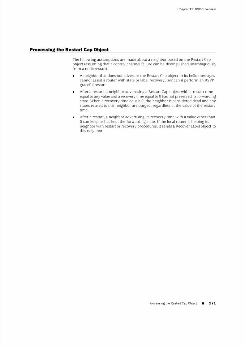
8/7/2019 Config Guide Mpls Applications
http://slidepdf.com/reader/full/config-guide-mpls-applications 309/547
Processing the Restart Cap Object
The following assumptions are made about a neighbor based on the Restart Capobject (assuming that a control channel failure can be distinguished unambiguouslyfrom a node restart):
■ A neighbor that does not advertise the Restart Cap object in its hello messagescannot assist a router with state or label recovery, nor can it perform an RSVPgraceful restart.
■ After a restart, a neighbor advertising a Restart Cap object with a restart timeequal to any value and a recovery time equal to 0 has not preserved its forwardingstate. When a recovery time equals 0, the neighbor is considered dead and anystates related to this neighbor are purged, regardless of the value of the restarttime.
■ After a restart, a neighbor advertising its recovery time with a value other than
0 can keep or has kept the forwarding state. If the local router is helping itsneighbor with restart or recovery procedures, it sends a Recover Label object tothis neighbor.
Processing the Restart Cap Object ■ 271
Chapter 11: RSVP Overview

8/7/2019 Config Guide Mpls Applications
http://slidepdf.com/reader/full/config-guide-mpls-applications 310/547
272 ■ Processing the Restart Cap Object
JUNOS 9.6 MPLS Applications Configuration Guide

8/7/2019 Config Guide Mpls Applications
http://slidepdf.com/reader/full/config-guide-mpls-applications 311/547
Chapter 12
RSVP Configuration Guidelines
This chapter describes how to configure RSVP and discusses the followingconfiguration tasks:
■ Minimum RSVP Configuration on page 273
■ Configuring RSVP and MPLS on page 274
■ Configuring RSVP Interfaces on page 275■ Configuring Node Protection or Link Protection for LSPs on page 281
■ Configuring Inter-AS Node and Link Protection on page 281
■ Configuring Link Protection on Interfaces Used by LSPs on page 282
■ Configuring RSVP Graceful Restart on page 289
■ Configuring Load Balancing Across RSVP LSPs on page 291
■ Configuring Timers for RSVP Refresh Messages on page 292
■ Preempting RSVP Sessions on page 293
■ Configuring MTU Signaling in RSVP on page 293
■ Configuring RSVP to Pop the Label on the Ultimate-Hop Router on page 295■ Disabling Adjacency Down and Neighbor Down Notification in IS-IS and
OSPF on page 295
■ Enabling Ultimate-Hop Popping on Point-to-Multipoint LSPs on page 296
■ Tracing RSVP Protocol Traffic on page 297
Minimum RSVP Configuration
To enable RSVP on a single interface, include the rsvp statement and specify theinterface using the interface statement. This is the minimum RSVP configuration. Allother RSVP configuration statements are optional.
rsvp {interface interface-name;
}
You can include these statements at the following hierarchy levels:
■ [edit protocols]
■ [edit logical-systems logical-system-name protocols]
Minimum RSVP Configuration ■ 273
8/7/2019 Config Guide Mpls Applications
http://slidepdf.com/reader/full/config-guide-mpls-applications 312/547
To enable RSVP on all interfaces, substitute all for the interface-name variable.
If you have configured interface properties on a group of interfaces and want todisable RSVP on one of the interfaces, include the disable statement:
interface interface-name {disable;
}
You can include this statement at the following hierarchy levels:
■ [edit protocols rsvp interface interface-name ]
■ [edit logical-systems logical-system-name protocols rsvp interface interface-name ]
Configuring RSVP and MPLS
The primary purpose of the JUNOS RSVP software is to support dynamic signalingwithin label-switched paths (LSPs). When you enable both MPLS and RSVP on arouter, MPLS becomes a client of RSVP. No additional configuration is required tobind MPLS and RSVP.
You can configure MPLS to set up signaled paths by using the label-switched-pathstatement at the [edit protocols mpls] hierarchy level. Each LSP translates into arequest for RSVP to initiate an RSVP session. This request is passed through theinternal interface between label switching and RSVP. After examining the requestinformation, checking RSVP states, and checking the local routing tables, RSVPinitiates one session for each LSP. The session is sourced from the local router andis destined for the target of the LSP.
When an RSVP session is successfully created, the LSP is set up along the pathscreated by the RSVP session. If the RSVP session is unsuccessful, RSVP notifies MPLSof its status. It is up to MPLS to initiate backup paths or continue retrying the initialpath.
To pass label-switching signaling information, RSVP supports four additional objects:Label Request object, Label object, Explicit Route object, and Record Route object.For an LSP to be set up successfully, all routers along the path must support MPLS,RSVP, and the four objects. Of the four objects, the Record Route object is notmandatory.
To configure MPLS and make it a client of RSVP, do the following:
■ Enable MPLS on all routers that will participate in the label switching (this is, on
all routers that might be part of a label-switching path).■ Enable RSVP on all routers and on all router interfaces that form the LSP.
■ Configure the routers at the beginning of the LSP.
Example: Configuring RSVP and MPLS
The following shows a sample configuration for a router at the beginning of an LSP:
274 ■ Configuring RSVP and MPLS
JUNOS 9.6 MPLS Applications Configuration Guide

8/7/2019 Config Guide Mpls Applications
http://slidepdf.com/reader/full/config-guide-mpls-applications 313/547
[edit]protocols {
mpls {label-switched-path sf-to-london {
to 192.168.1.4;}}rsvp {
interface so-0/0/0;}
}
The following shows a sample configuration for all the other routers that form theLSP:
[edit]protocols {
mpls {
interface so-0/0/0;}rsvp {
interface so-0/0/0;}
}
Configuring RSVP Interfaces
The following sections describe how to configure RSVP interfaces:
■ Configuring RSVP Refresh Reduction on page 275
■ Configuring the RSVP Hello Interval on page 278
■ Configuring RSVP Authentication on page 278
■ Configuring the Bandwidth Subscription for Class Types on page 279
■ Configuring the RSVP Update Threshold on an Interface on page 279
■ Configuring RSVP for Unnumbered Interfaces on page 280
Configuring RSVP Refresh Reduction
You can configure RSVP refresh reduction on each interface by including the followingstatements in the interface configuration:
■ aggregate—Enable all RSVP refresh reduction features: RSVP message bundling,
RSVP message ID, reliable message delivery, and summary refresh.■ no-aggregate—Disable RSVP message bundling and summary refresh.
■ reliable—Enable RSVP message ID and reliable message delivery.
■ no-reliable—Disable RSVP message ID, reliable message delivery, and summaryrefresh.
For more information on RSVP refresh reduction, see “RSVP Refresh Reduction” onpage 262.
Configuring RSVP Interfaces ■ 275
Chapter 12: RSVP Configuration Guidelines

8/7/2019 Config Guide Mpls Applications
http://slidepdf.com/reader/full/config-guide-mpls-applications 314/547
Table 6 on page 276 lists various combinations of the RSVP refresh reductionconfiguration statements and how they alter the behavior of the JUNOS Software.The table describes only the expected behavior based on the configuration on therouter. The actual behavior is dictated not only by the local configuration on this
router, but also on the refresh reduction capabilities of its RSVP neighbors. Note thatby configuring the aggregate statement, you enable all RSVP refresh reduction features,including reliable message delivery.
Table 6: RSVP Refresh Reduction Behavior
Receive CapabilitySend CapabilityConfiguration Statement
BundleAck/Nack (allmessages)SummaryRefresh
RR bit = 1BundleMessage ID(Path/Resv messages)Ack/Nack (allmessages)Summary Refresh
aggregate or aggregate andreliable
BundleMessage ID (allmessages)
RR bit = 1BundleAck/Nack (allmessages)
aggregate and no-reliable
BundleMessage ID (allmessages)Ack/Nack
RR bit = 0Message ID (Path/Resvmessages)Ack/Nack (all messages)
reliable or reliable andno-aggregate
The send capability shown in Table 6 on page 276 lists the RSVP messages and objectsrelated to RSVP refresh reduction that the router is capable of sending. This does notmean that all these messages are exchanged between this router and a neighbor.For example, if the router is configured with the aggregate statement, but RSVPrefresh reduction is not enabled on its neighbor, then no Summary Refresh messageis sent to this neighbor even though the router is capable of sending it.
The receive capability shown in Table 6 on page 276 lists the messages and objectsrelated to RSVP refresh reduction that the router is capable of receiving and processingwithout generating any errors or resulting in error conditions.
If the no-reliable statement is configured on the router (reliable message delivery isdisabled), the router accepts RSVP messages that include the Message ID object butignore the Message ID object and continue performing standard message processing.No error is generated in this case, and RSVP operates normally.
However, not all combinations between two neighbors with different refresh reductioncapabilities function correctly. For example, a router is configured with either theaggregate statement and no-reliable statement or with the reliable and no-aggregatestatements. If an RSVP neighbor sends a Summary Refresh object to this router, noerror is generated, but the Summary Refresh object cannot be processed.
Consequently, RSVP states can time out on this router if the neighbor is relying onlyon Summary Refresh to refresh those RSVP states.
We recommend, unless there are specific requirements, that you configure RSVPrefresh reduction in a similar manner on each RSVP neighbor.
To enable all RSVP refresh reduction features on an interface, include the aggregatestatement:
aggregate;
276 ■ Configuring RSVP Interfaces
JUNOS 9.6 MPLS Applications Configuration Guide

8/7/2019 Config Guide Mpls Applications
http://slidepdf.com/reader/full/config-guide-mpls-applications 315/547
You can include this statement at the following hierarchy levels:
■ [edit protocols rsvp interface interface-name]
■ [edit logical-systems logical-system-name protocols rsvp interface interface-name]
To disable RSVP message bundling and summary refresh, include the no-aggregatestatement:
no-aggregate;
You can include this statement at the following hierarchy levels:
■ [edit protocols rsvp interface interface-name]
■ [edit logical-systems logical-system-name protocols rsvp interface interface-name]
To enable RSVP message ID and reliable message delivery on an interface, include
the reliable statement:reliable;
You can include this statement at the following hierarchy levels:
■ [edit protocols rsvp interface interface-name]
■ [edit logical-systems logical-system-name protocols rsvp interface interface-name]
To disable RSVP message ID, reliable message delivery, and summary refresh, includethe no-reliable statement:
no-reliable;
You can include this statement at the following hierarchy levels:
■ [edit protocols rsvp interface interface-name]
■ [edit logical-systems logical-system-name protocols rsvp interface interface-name]
Determining the Refresh Reduction Capability of RSVP Neighbors
To determine the RSVP refresh reduction capability of an RSVP neighbor, you needthe following information:
■ The RR bit advertised by the neighbor
■ The local configuration of RSVP refresh reduction
■ The actual RSVP messages received from the neighbor
To obtain this information, you can issue a show rsvp neighbor detail command. Thefollowing is a sample of output from this command:
user@host> show rsvp neighbor detail
RSVP neighbor: 6 learned
Address: 192.168.224.178 via: fxp1.0 status: Up
Configuring RSVP Interfaces ■ 277
Chapter 12: RSVP Configuration Guidelines

8/7/2019 Config Guide Mpls Applications
http://slidepdf.com/reader/full/config-guide-mpls-applications 316/547
Last changed time: 10:06, Idle: 5 sec, Up cnt: 1, Down cnt: 0
Message received: 36
Hello: sent 69, received: 69, interval: 9 sec
Remote instance: 0x60b8feba, Local instance: 0x74bc7a8d
Refresh reduction: not operational
Address: 192.168.224.186 via: fxp2.0 status: Down
Last changed time: 10:17, Idle: 40 sec, Up cnt: 0, Down cnt: 0
Message received: 6
Hello: sent 20, received: 0, interval: 9 sec
Remote instance: 0x0, Local instance: 0x2ae1b339
Refresh reduction: incomplete
Remote end: disabled, Ack-extension: enabled
Address: 192.168.224.188 via: fxp2.0 status: Up
Last changed time: 4:15, Idle: 0 sec, Up cnt: 1, Down cnt: 0
Message received: 55
Hello: sent 47, received: 31, interval: 9 sec
Remote instance: 0x6436a35b, Local instance: 0x663849f0
Refresh reduction: operational
Remote end: enabled, Ack-extension: enabled
For more information on the show rsvp neighbor detail command, see the JUNOS Routing Protocols and Policies Command Reference.
Configuring the RSVP Hello Interval
RSVP monitors the status of the interior gateway protocol (IGP) (IS-IS or OSPF)neighbors and relies on the IGP protocols to detect when a node fails. If an IGPprotocol declares a neighbor down (because hello packets are no longer beingreceived), RSVP also brings down that neighbor. However, the IGP protocols andRSVP still act independently when bringing a neighbor up.
For Juniper Networks routers, configuring a shorter or longer RSVP hello interval hasno impact on whether or not an RSVP session is brought down. RSVP sessions arekept up even if RSVP hello packets are no longer being received. RSVP sessions aremaintained until either the router stops receiving IGP hello packets or the RSVP Pathand Resv messages time out.
However, the RSVP hello interval might impact when another vendor’s equipmentbrings down an RSVP session. For example, a neighboring non-Juniper Networksrouter might be configured to monitor RSVP hello packets.
To modify how often RSVP sends hello packets, include the hello-interval statement:
hello-interval seconds;
For a list of hierarchy levels at which you can include this statement, see the statementsummary section.
Configuring RSVP Authentication
All RSVP protocol exchanges can be authenticated to guarantee that only trustedneighbors participate in setting up reservations. By default, RSVP authentication isdisabled.
278 ■ Configuring RSVP Interfaces
JUNOS 9.6 MPLS Applications Configuration Guide

8/7/2019 Config Guide Mpls Applications
http://slidepdf.com/reader/full/config-guide-mpls-applications 317/547
RSVP authentication uses a Hashed Message Authentication Code (HMAC)-MD5message-based digest. This scheme produces a message digest based on a secretauthentication key and the message contents. (The message contents also include asequence number.) The computed digest is transmitted with RSVP messages. Once
you have configured authentication, all received and transmitted RSVP messageswith all neighbors are authenticated on this interface.
MD5 authentication provides protection against forgery and message modification.It also can prevent replay attacks. However, it does not provide confidentiality,because all messages are sent in clear text.
By default, authentication is disabled. To enable authentication, configure a key oneach interface by including the authentication-key statement:
authentication-key key ;
You can include this statement at the following hierarchy levels:
■ [edit protocols rsvp interface interface-name]
■ [edit logical-systems logical-system-name protocols rsvp interface interface-name]
Configuring the Bandwidth Subscription for Class Types
By default, RSVP allows 100 percent the bandwidth for a class type to be used forRSVP reservations. When you oversubscribe a class type for a multiclass LSP, theaggregate demand of all RSVP sessions is allowed to exceed the actual capacity of the class type.
For detailed instructions on how to configure the bandwidth subscription for classtypes, see “Configuring the Bandwidth Subscription Percentage for LSPs” on page
124.
Configuring the RSVP Update Threshold on an Interface
The interior gateway protocols (IGPs) maintain the traffic engineering database, butthe current available bandwidth on the traffic engineering database links originatesfrom RSVP. When a link’s bandwidth changes, RSVP informs the IGPs, which canthen update the traffic engineering database and forward the new bandwidthinformation to all network nodes. The network nodes then know how much bandwidthis available on the traffic engineering database link (local or remote), and CSPF cancorrectly compute the paths.
However, IGP updates can consume excessive system resources. Depending on thenumber of nodes in a network, it might not be desirable to perform an IGP updatefor small changes in bandwidth. By configuring the update-threshold statement atthe [edit protocols rsvp] hierarchy level, you can adjust the threshold at which a changein the reserved bandwidth triggers an IGP update.
You can configure a value of from 1 percent through 20 percent (the default is10 percent) for when to trigger an IGP update. If the change in the reserved bandwidthis greater than or equal to the configured threshold percentage of the static bandwidthon that interface, then an IGP update occurs. For example, if you have configured
Configuring RSVP Interfaces ■ 279
Chapter 12: RSVP Configuration Guidelines

8/7/2019 Config Guide Mpls Applications
http://slidepdf.com/reader/full/config-guide-mpls-applications 318/547
the update-threshold statement to be 15 percent and the router discovers that thereserved bandwidth on a link has changed by 10 percent of the link bandwidth, RSVPdoes not trigger an IGP update. However, if the reserved bandwidth on a link changesby 20 percent of the link bandwidth, RSVP triggers an IGP update.
To adjust the threshold at which a change in the reserved bandwidth triggers an IGPupdate, include the update-threshold statement:
update-threshold percentage;
You can include this statement at the following hierarchy levels:
■ [edit protocols rsvp interface interface-name]
■ [edit logical-systems logical-system-name protocols rsvp interface interface-name]
Because of the update threshold, it is possible for Constrained Shortest Path First(CSPF) to compute a path using outdated traffic engineering database bandwidth
information on a link. If RSVP attempts to establish an LSP over that path, it mightfind that there is insufficient bandwidth on that link. When this happens, RSVPtriggers an IGP traffic engineering database update, flooding the updated bandwidthinformation on the network. CSPF can then recompute the path by using the updatedbandwidth information, and attempt to find a different path, avoiding the congestedlink. Note that this functionality is the default and does not need any additionalconfiguration.
You can configure the rsvp-error-hold-time statement at the [edit protocols mpls]hierarchy level or the [edit logical-systems logical-system-name protocols mpls] hierarchylevel to improve the accuracy of the traffic engineering database (including theaccuracy of bandwidth estimates for LSPs) using information provided by PathErrmessages. See “Improving Traffic Engineering Database Accuracy with RSVP PathErr
Messages”
on page 60.
Configuring RSVP for Unnumbered Interfaces
The JUNOS Software supports RSVP traffic engineering over unnumbered interfaces.Traffic engineering information about unnumbered links is carried in the IGP trafficengineering extensions for OSPF and IS-IS as described in RFC 4203, OSPF Extensionsin Support of Generalized Multi-Protocol Label Switching (GMPLS), and RFC 4205, Intermediate System to Intermediate System (IS-IS) Extensions in Support of Generalized Multi-Protocol Label Switching (GMPLS). Unnumbered links can also be specified inthe MPLS traffic engineering signaling as described in RFC 3477, SignallingUnnumbered Links in Resource ReSerVation Protocol - Traffic Engineering (RSVP-TE).This feature allows you avoid having to configure IP addresses for each interface
participating in the RSVP-signaled network.
To configure RSVP for unnumbered interfaces, you must configure the router witha router ID using the router-id statement specified at the [edit routing-options] hierarchylevel. The router ID must be available for routing (you can typically use the loopbackaddress). The RSVP control messages for the unnumbered links are sent using therouter ID address (rather than a randomly selected address).
To configure link protection and fast reroute on a router with unnumbered interfacesenabled, you must configure at least two addresses. We recommend that you
280 ■ Configuring RSVP Interfaces
JUNOS 9.6 MPLS Applications Configuration Guide

8/7/2019 Config Guide Mpls Applications
http://slidepdf.com/reader/full/config-guide-mpls-applications 319/547
configure a secondary interface on the loopback in addition to configuring the routerID.
Configuring Node Protection or Link Protection for LSPs
When you configure node protection or link protection on a router, bypass LSPs arecreated to the next-hop or next-next-hop routers for the LSPs traversing the router.You must configure node protection or link protection for each LSP that you wantprotected. To extend protection along the entire path used by an LSP, you mustconfigure protection on each router that the LSP traverses.
To configure node protection on a router for a specified LSP, include thenode-link-protection statement:
node-link-protection;
You can include this statement at the following hierarchy levels:
■ [edit protocols mpls label-switched-path lsp-name]
■ [edit logical-systems logical-system-nameprotocols mpls label-switched-path lsp-name]
To configure link protection on a router for a specified LSP, include the link-protection(MPLS) statement:
link-protection;
You can include this statement at the following hierarchy levels:
■ [edit protocols mpls label-switched-path lsp-name]
■ [edit logical-systems logical-system-nameprotocols mpls label-switched-path lsp-name]
NOTE: To complete the configuration of node or link protection, you must alsoconfigure link protection on all unidirectional RSVP interfaces that the LSPs traverse,as described in “Configuring Link Protection on Interfaces Used by LSPs” on page282.
Configuring Inter-AS Node and Link Protection
To interoperate with other vendors’ equipment, the JUNOS Software supports therecord route object (RRO) node ID subobject for use in inter-AS link and nodeprotection configurations. The RRO node ID subobject is defined in RFC 4561, Definition of a Record Route Object (RRO) Node-Id Sub-Object . This functionality isenabled by default in JUNOS Release 9.4 and later.
If you have Juniper Networks routers running JUNOS Release 9.4 and later releasesin the same MPLS-TE network as routers running JUNOS Release 8.4 and earlierreleases, you might need to disable the RRO node ID subobject by configuring theno-node-id-subobject statement:
no-node-id-subobject;
Configuring Node Protection or Link Protection for LSPs ■ 281
Chapter 12: RSVP Configuration Guidelines

8/7/2019 Config Guide Mpls Applications
http://slidepdf.com/reader/full/config-guide-mpls-applications 320/547
You can include this statement at the following hierarchy levels:
■ [edit protocols rsvp]
■ [edit logical-systems logical-system-name protocols rsvp]
Configuring Link Protection on Interfaces Used by LSPs
When you configure node protection or link protection on a router for LSPs asdescribed in “Configuring Node Protection or Link Protection for LSPs” on page 281,you also must configure the link-protection statement on the RSVP interfaces used bythe LSPs.
To configure link protection on the interfaces used by the LSPs, include thelink-protection (MPLS) statement:
link-protection {
disable;admin-group
exclude group-names;include-all group-names;include-any group-names;
}bandwidth bps;bypass bypass-name {
bandwidth bps;hop-limit number ;no-cspf ;path address <strict | loose>;priority setup-priority reservation-priority ;to address;
}class-of-service cos-value;hop-limit number ;max-bypasses number ;no-cspf ;no-node-protection;optimize-timer seconds;path address <strict | loose>;priority setup-priority reservation-priority ;subscription percent {
ct0 percent;ct1 percent;ct2 percent;ct3 percent;
}}
You can include this statement at the following hierarchy levels:
■ [edit protocols rsvp interface interface-name]
■ [edit logical-systems logical-system-name protocols rsvp interface interface-name]
All the statements under link-protection are optional.
282 ■ Configuring Link Protection on Interfaces Used by LSPs
JUNOS 9.6 MPLS Applications Configuration Guide

8/7/2019 Config Guide Mpls Applications
http://slidepdf.com/reader/full/config-guide-mpls-applications 321/547
The following sections describe how to configure link protection:
■ Configuring Bypass LSPs on page 283
■ Configuring Administrative Groups for Bypass LSPs on page 284
■ Configuring the Bandwidth for Bypass LSPs on page 284
■ Configuring Class of Service for Bypass LSPs on page 285
■ Configuring the Hop Limit for Bypass LSPs on page 285
■ Configuring the Maximum Number of Bypass LSPs on page 286
■ Disabling CSPF for Bypass LSPs on page 287
■ Disabling Node Protection for Bypass LSPs on page 287
■ Configuring the Optimization Interval for Bypass LSPs on page 287
■ Configuring an Explicit Path for Bypass LSPs on page 288
■ Configuring the Amount of Bandwidth Subscribed for Bypass LSPs on page 288
■ Configuring Priority and Preemption for Bypass LSPs on page 289
Configuring Bypass LSPs
You can configure specific bandwidth and path constraints for a bypass LSP. Youcan also individually configure each bypass LSP generated when you enable multiplebypass LSPs. If you do not configure the bypass LSPs individually, they all share thesame path and bandwidth constraints (if any).
If you specify the bandwidth, hop-limit, and path statements for the bypass LSP, thesevalues take precedence over the values configured at the [edit protocols rsvp interfaceinterface-name link-protection] hierarchy level. The other attributes (subscription,no-node-protection, and optimize-timer) are inherited from the general constraints.
To configure a bypass LSP, include the bypass statement:
bypass bypass-name {bandwidth bps;class-of-service cos-value;hop-limit number ;no-cspf ;path address <strict | loose>;priority setup-priority reservation-priority ;to address;
}
You can include this statement at the following hierarchy levels:
■ [edit protocols rsvp interface interface-name link-protection]
■ [edit logical-systems logical-system-name protocols rsvp interface interface-name
link-protection]
Configuring Link Protection on Interfaces Used by LSPs ■ 283
Chapter 12: RSVP Configuration Guidelines
8/7/2019 Config Guide Mpls Applications
http://slidepdf.com/reader/full/config-guide-mpls-applications 322/547
Configuring the Next-Hop or Next-Next-Hop Node Address for Bypass LSPs
If you configure a bypass LSP, you must also configure the to statement. The to
statement specifies the address for the interface of the immediate next-hop node(for link protection) or the next-next-hop node (for node-link protection). The addressspecified determines whether this is a link protection bypass or a node-link protectionbypass. On multiaccess networks (for example, a LAN), this address is also used tospecify which next-hop node is being protected.
Configuring Administrative Groups for Bypass LSPs
Administrative groups, also known as link coloring or resource class, are manuallyassigned attributes that describe the “color” of links, such that links with the samecolor conceptually belong to the same class. You can use administrative groups toimplement a variety of policy-based LSP setups. You can configure administrative
groups for bypass LSPs. For more information about configuring administrativegroups, see “Configuring Administrative Groups” on page 96.
To configure administrative groups for bypass LSPs, include the admin-group statement:
admin-group {exclude group-names;include-all group-names;include-any group-names;
}
To configure an administrative group for all of the bypass LSPs, include theadmin-group statement at the following hierarchy levels:
■ [edit protocols rsvp interface interface-name link-protection]
■ [edit logical-systems logical-system-name protocols rsvp interface interface-name
link-protection]
To configure an administrative groups for a specific bypass LSP, include theadmin-group statement at the following hierarchy levels:
■ [edit protocols rsvp interface interface-name link-protection bypass bypass-name]
■ [edit logical-systems logical-system-name protocols rsvp interface interface-name
link-protection bypass bypass-name]
Configuring the Bandwidth for Bypass LSPs
You can specify the amount of bandwidth allocated for automatically generatedbypass LSPs or you can individually specify the amount of bandwidth allocated foreach LSP.
To specify the bandwidth allocation, include the bandwidth statement:
bandwidth bps;
284 ■ Configuring Link Protection on Interfaces Used by LSPs
JUNOS 9.6 MPLS Applications Configuration Guide

8/7/2019 Config Guide Mpls Applications
http://slidepdf.com/reader/full/config-guide-mpls-applications 323/547
For automatically generated bypass LSPs, include the bandwidth statement at thefollowing hierarchy levels:
■ [edit protocols rsvp interface interface-name link-protection]
■ [edit logical-systems logical-system-name protocols rsvp interface interface-namelink-protection]
For individually configured bypass LSPs, include the bandwidth statement at thefollowing hierarchy levels:
■ [edit protocols rsvp interface interface-name link-protection bypass bypass-name]
■ [edit logical-systems logical-system-name protocols rsvp interface interface-name
link-protection bypass bypass-name]
If you have enabled multiple bypass LSPs, this statement is required. See also“Configuring the Maximum Number of Bypass LSPs” on page 286.
Configuring Class of Service for Bypass LSPs
You can specify the class-of-service value for bypass LSPs by including theclass-of-service statement:
class-of-service cos-value;
To apply a class-of-service value to all the automatically generated bypass LSPs,include the class-of-service statement at the following hierarchy levels:
■ [edit protocols rsvp interface interface-name link-protection]
■ [edit logical-systems logical-system-name protocols rsvp interface interface-name
link-protection]
To configure a class-of-service value for a specific bypass LSPs, include theclass-of-service statement at the following hierarchy levels:
■ [edit protocols rsvp interface interface-name link-protection bypass bypass-name]
■ [edit logical-systems logical-system-name protocols rsvp interface interface-name
link-protection bypass bypass-name]
Configuring the Hop Limit for Bypass LSPs
You can specify the maximum number of hops a bypass can traverse. By default,each bypass can traverse a maximum of 255 hops (the ingress and egress routerscount as one hop each, so the minimum hop limit is two).
To configure the hop limit for bypass LSPs, include the hop-limit statement:
hop-limit number ;
For automatically generated bypass LSPs, include the hop-limit statement at thefollowing hierarchy levels:
Configuring Link Protection on Interfaces Used by LSPs ■ 285
Chapter 12: RSVP Configuration Guidelines

8/7/2019 Config Guide Mpls Applications
http://slidepdf.com/reader/full/config-guide-mpls-applications 324/547
■ [edit protocols rsvp interface interface-name link-protection]
■ [edit logical-systems logical-system-name protocols rsvp interface interface-name
link-protection]
For individually configured bypass LSPs, include the hop-limit statement at thefollowing hierarchy levels:
■ [edit protocols rsvp interface interface-name link-protection bypass bypass-name]
■ [edit logical-systems logical-system-name protocols rsvp interface interface-name
link-protection bypass bypass-name]
Configuring the Maximum Number of Bypass LSPs
You can specify the maximum number of dynamic bypass LSPs permitted forprotecting an interface using the max-bypasses statement at the [edit protocols rsvp
interface interface-name link-protection] hierarchy level. When this statement isconfigured, multiple bypasses for link protection are enabled. Call admission control(CAC) is also enabled.
By default, this option is disabled and only one bypass is enabled for each interface.You can configure a value of between 0 through 99 for the max-bypasses statement.Configuring a value of 0 prevents the creation of any dynamic bypass LSPs for theinterface. If you configure a value of 0 for the max-bypasses statement, you need toconfigure one or more static bypass LSPs to enable link protection on the interface.
If you configure the max-bypasses statement, you must also configure the bandwidthstatement (discussed in “Configuring the Bandwidth for Bypass LSPs” on page 284).
To configure the maximum number of bypass LSPs for a protected interface, includethe max-bypasses statement:
max-bypasses number ;
You can include this statement at the following hierarchy levels:
■ [edit protocols rsvp interface interface-name link-protection]
■ [edit logical-systems logical-system-name protocols rsvp interface interface-name
link-protection]
286 ■ Configuring Link Protection on Interfaces Used by LSPs
JUNOS 9.6 MPLS Applications Configuration Guide

8/7/2019 Config Guide Mpls Applications
http://slidepdf.com/reader/full/config-guide-mpls-applications 325/547
Disabling CSPF for Bypass LSPs
Under certain circumstances, you might need to disable CSPF computation for bypassLSPs and use the configured Explicit Route Object (ERO) if available. For example,a bypass LSP might need to traverse multiple OSPF areas or IS-IS levels, preventingthe CSPF computation from working. To ensure that link and node protection functionproperly in this case, you have to disable CSPF computation for the bypass LSP.
You can disable CSPF computation for all bypass LSPs or for specific bypass LSPs.
To disable CSPF computation for bypass LSPs, include the no-cspf statement:
no-cspf ;
For a list of hierarchy levels where you can include this statement, see the statementsummary for this statement.
Disabling Node Protection for Bypass LSPs
You can disable node protection on the RSVP interface. Link protection remainsactive. When this option is configured, the router can only initiate a next-hop bypass,not a next-next-hop bypass.
To disable node protection for bypass LSPs, include the no-node-protection statement:
no-node-protection;
You can include this statement at the following hierarchy levels:
■ [edit protocols rsvp interface interface-name link-protection]
■ [edit logical-systems logical-system-name protocols rsvp interface interface-name
link-protection]
Configuring the Optimization Interval for Bypass LSPs
You can configure an optimization interval for bypass LSPs. At the end of this interval,an optimization process is initiated that attempts to either minimize the number of bypasses currently in use, minimize the total amount of bandwidth reserved for allof the bypasses, or both. You can configure an optimization interval from 1 through65,535 seconds. A default value of 0 disables bypass LSP optimization.
To configure the optimization interval for bypass LSPs, include the optimize-timer
statement:
optimize-timer seconds;
You can include this statement at the following hierarchy levels:
■ [edit protocols rsvp interface interface-name link-protection]
■ [edit logical-systems logical-system-name protocols rsvp interface interface-name
link-protection]
Configuring Link Protection on Interfaces Used by LSPs ■ 287
Chapter 12: RSVP Configuration Guidelines
8/7/2019 Config Guide Mpls Applications
http://slidepdf.com/reader/full/config-guide-mpls-applications 326/547
Configuring an Explicit Path for Bypass LSPs
By default, when you establish a bypass LSP to an adjacent neighbor, CSPF is usedto discover the least-cost path. The path statement allows you to configure an explicitpath (a sequence of strict or loose routes), giving you control over where and howthe bypass LSP is established. To configure an explicit path, include the pathstatement:
path address <strict | loose>;
For automatically generated bypass LSPs, include the path statement at the followinghierarchy levels:
■ [edit protocols rsvp interface interface-name link-protection]
■ [edit logical-systems logical-system-name protocols rsvp interface interface-name
link-protection]
For individually configured bypass LSPs, include the path statement at the followinghierarchy levels:
■ [edit protocols rsvp interface interface-name link-protection bypass bypass-name]
■ [edit logical-systems logical-system-name protocols rsvp interface interface-name
link-protection bypass bypass-name]
Configuring the Amount of Bandwidth Subscribed for Bypass LSPs
You can configure the amount of bandwidth subscribed to bypass LSPs. You canconfigure the bandwidth subscription for the whole bypass LSP or for each class typethat might traverse the bypass LSP. You can configure any value between 1 percentand 65,535 percent. By configuring a value less than 100 percent, you areundersubscribing the bypass LSPs. By configuring a value greater than 100 percent,you are oversubscribing the bypass LSPs.
The ability to oversubscribe the bandwidth for the bypass LSPs makes it possible tomore efficiently use network resources. You can configure the bandwidth for thebypass LSPs based on the average network load as opposed to the peak load.
To configure the amount of bandwidth subscribed for bypass LSPs, include thesubscription statement:
subscription percentage {
ct0 percentage;ct1 percentage;ct2 percentage;ct3 percentage;
}
You can include this statement at the following hierarchy levels:
■ [edit protocols rsvp interface interface-name link-protection]
288 ■ Configuring Link Protection on Interfaces Used by LSPs
JUNOS 9.6 MPLS Applications Configuration Guide

8/7/2019 Config Guide Mpls Applications
http://slidepdf.com/reader/full/config-guide-mpls-applications 327/547
■ [edit logical-systems logical-system-name protocols rsvp interface interface-name
link-protection]
Configuring Priority and Preemption for Bypass LSPs
When there is insufficient bandwidth to establish a more important LSP, you mightwant to tear down a less important existing LSP to release the bandwidth. You dothis by preempting the existing LSP.
For more detailed information on configuring setup priority and reservation priorityfor LSPs, see “Configuring Priority and Preemption for LSPs” on page 102.
To configure the bypass LSP’s priority and preemption properties, include the prioritystatement:
priority setup-priority reservation-priority ;
For a list of hierarchy levels at which you can include this statement, see the statementsummary section for this statement.
Configuring RSVP Graceful Restart
The following RSVP graceful restart configurations are possible:
■ Graceful restart and helper mode are both enabled (the default).
■ Graceful restart is enabled but helper mode is disabled. A router configured inthis way can restart gracefully, but cannot help a neighbor with its restart andrecovery procedures.
■
Graceful restart is disabled but helper mode is enabled. A router configured inthis way cannot restart gracefully, but can help a restarting neighbor.
■ Graceful restart and helper mode both are disabled. This configuration completelydisables RSVP graceful restart (including restart and recovery procedures andhelper mode). The router behaves like a router that does not support RSVPgraceful restart.
NOTE: In order to turn on RSVP graceful restart, you must set the global gracefulrestart timer to at least 180 seconds.
The following sections describe how to configure RSVP graceful restart:
■ Enabling Graceful Restart for All Routing Protocols on page 290
■ Disabling Graceful Restart for RSVP on page 290
■ Disabling RSVP Helper Mode on page 290
■ Configuring the Maximum Helper Recovery Time on page 290
■ Configuring the Maximum Helper Restart Time on page 290
Configuring RSVP Graceful Restart ■ 289
Chapter 12: RSVP Configuration Guidelines

8/7/2019 Config Guide Mpls Applications
http://slidepdf.com/reader/full/config-guide-mpls-applications 328/547
Enabling Graceful Restart for All Routing Protocols
To enable graceful restart for RSVP, you need to enable graceful restart for all theprotocols that support graceful restart on the router. For more information aboutgraceful restart, see the JUNOS Routing Protocols Configuration Guide.
To enable graceful restart on the router, include the graceful-restart statement:
graceful-restart;
You can include this statement at the following hierarchy levels:
■ [edit routing-options]
■ [edit logical-systems logical-system-name routing-options]
Disabling Graceful Restart for RSVP
By default, RSVP graceful restart and RSVP helper mode are enabled when you enablegraceful restart. However, you can disable one or both of these capabilities.
To disable RSVP graceful restart and recovery, include the disable statement at the[edit protocols rsvp graceful-restart] hierarchy level:
disable;
Disabling RSVP Helper Mode
To disable RSVP helper mode, include the helper-disable statement at the [edit protocols
rsvp graceful-restart] hierarchy level:
helper-disable;
Configuring the Maximum Helper Recovery Time
To configure the amount of time the router retains the state of its RSVP neighborswhile they undergo a graceful restart, include the maximum-helper-recovery-timestatement at the [edit protocols rsvp graceful-restart] hierarchy level. This value isapplied to all neighboring routers, so it should be based on the time required by theslowest RSVP neighbor to recover.
maximum-helper-recovery-time seconds;
Configuring the Maximum Helper Restart Time
To configure the delay between when the router discovers that a neighboring routerhas gone down and when it declares the neighbor down, include themaximum-helper-restart-time statement at the [edit protocols rsvp graceful-restart]hierarchy level. This value is applied to all neighboring routers, so it should be basedon the time required by the slowest RSVP neighbor to restart.
290 ■ Configuring RSVP Graceful Restart
JUNOS 9.6 MPLS Applications Configuration Guide

8/7/2019 Config Guide Mpls Applications
http://slidepdf.com/reader/full/config-guide-mpls-applications 329/547
maximum-helper-restart-time seconds;
Configuring Load Balancing Across RSVP LSPs
By default, when you have configured several RSVP LSPs to the same egress router,the LSP with the lowest metric is selected and carries all traffic. If all of the LSPs havethe same metric, one of the LSPs is selected at random and all traffic is forwardedover it.
Alternatively, you can load balance traffic across all of the LSPs by enabling per-packetload balancing.
To enable per-packet load balancing on an ingress LSP, configure the policy-statementstatement as follows:
[edit policy-options]policy-statement policy-name {
then {load-balance per-packet;
}accept;
}
You then need to apply this statement as an export policy to the forwarding table.For more information on how to configure the policy-statement statement, see the JUNOS Policy Framework Configuration Guide.
Once per-packet load balancing is applied, traffic is distributed equally between theLSPs (by default).
You need to configure per-packet load balancing if you want to enable PFE fast
reroute. To enable PFE fast reroute, include the policy statement for per-packet loadbalancing shown in this section in the configuration of each of the routers where areroute might take place. See also “Configuring Fast Reroute” on page 78.
You can also load-balance the traffic between the LSPs in proportion to the amountof bandwidth configured for each LSP. This capability can better distribute traffic innetworks with asymmetric bandwidth capabilities across external links, since theconfigured bandwidth of an LSP typically reflects the traffic capacity of that LSP.
To configure RSVP LSP load balancing, include the load-balance statement with thebandwidth option:
load-balance {bandwidth;
}
You can configure this statement at the following hierarchy levels:
■ [edit protocols rsvp]
■ [edit logical-systems logical-system-name protocols rsvp]
Keep the following information in mind when you use the load-balance statement:
Configuring Load Balancing Across RSVP LSPs ■ 291
Chapter 12: RSVP Configuration Guidelines

8/7/2019 Config Guide Mpls Applications
http://slidepdf.com/reader/full/config-guide-mpls-applications 330/547
■ If you configure the load-balance statement, the behavior of currently runningLSPs is not altered. To force currently running LSPs to use the new behavior,you can issue a clear mpls lsp command.
■
Theload-balance
statement only applies to ingress LSPs that have per-packetload balancing enabled.
■ For differentiated services aware traffic engineered LSPs, the bandwidth of anLSP is calculated by summing the bandwidth of all of the class types.
Configuring Timers for RSVP Refresh Messages
RSVP uses two related timing parameters:
■ refresh-time—The refresh time controls the interval between the generation of successive refresh messages. The default value for the refresh time is 45 seconds.This number is derived from the refresh-time statement’s default value of 30,
multiplied by a fixed value of 1.5. This computation differs from RFC 2205,which states that the refresh time should be multiplied by a random value in therange from 0.5 through 1.5.
Refresh messages include path and Resv messages. Refresh messages are sentperiodically so that reservation states in neighboring nodes do not time out. Eachpath and Resv message carries the refresh timer value, and the receiving nodeextracts this value from the messages.
■ keep-multiplier—The keep multiplier is a small, locally configured integer from 1through 255. The default value is 3. It indicates the number of messages thatcan be lost before a particular state is declared stale and must be deleted. Thekeep multiplier directly affects the lifetime of an RSVP state.
To determine the lifetime of a reservation state, use the following formula:
lifetime = (keep-multiplier + 0.5) x (1.5 x refresh-time)
In the worst case, (keep-multiplier – 1) successive refresh messages must be lost beforea reservation state is deleted.
Juniper Networks does not recommend configuring a short RSVP hello timer. If quickdiscovery of a failed neighbor is needed, configure short IGP (OSPF or IS-IS) hellotimers.
By default, the refresh timer value is 30 seconds. To modify this value, include therefresh-time statement:
refresh-time seconds;
You can include this statement at the following hierarchy levels:
■ [edit protocols rsvp]
■ [edit logical-systems logical-system-name protocols rsvp]
292 ■ Configuring Timers for RSVP Refresh Messages
JUNOS 9.6 MPLS Applications Configuration Guide

8/7/2019 Config Guide Mpls Applications
http://slidepdf.com/reader/full/config-guide-mpls-applications 331/547
The default value of the keep multiplier is 3. To modify this value, include thekeep-multiplier statement:
keep-multiplier number ;
You can include this statement at the following hierarchy levels:
■ [edit protocols rsvp]
■ [edit logical-systems logical-system-name protocols rsvp]
Preempting RSVP Sessions
Whenever bandwidth is insufficient to handle all RSVP sessions, you can control thepreemption of RSVP sessions. By default, an RSVP session is preempted only by anew higher-priority session.
To always preempt a session when the bandwidth is insufficient, include thepreemption statement with the aggressive option:
preemption aggressive;
You can include this statement at the following hierarchy levels:
■ [edit protocols rsvp]
■ [edit logical-systems logical-system-name protocols rsvp]
To disable RSVP session preemption, include the preemption statement with thedisabled option:
preemption disabled;
To return to the default (that is, preempt a session only for a new higher-prioritysession), include the preemption statement with the normal option:
preemption normal;
You can include this statement at the following hierarchy levels:
■ [edit protocols rsvp]
■ [edit logical-systems logical-system-name protocols rsvp]
Configuring MTU Signaling in RSVP
To configure maximum transmission unit (MTU) signaling in RSVP, you need toconfigure MPLS to allow IP packets to be fragmented before they are encapsulatedin MPLS. You also need to configure MTU signaling in RSVP. For troubleshootingpurposes, you can configure MTU signaling alone without enabling packetfragmentation.
To configure MTU signaling in RSVP, include the path-mtu statement:
Preempting RSVP Sessions ■ 293
Chapter 12: RSVP Configuration Guidelines

8/7/2019 Config Guide Mpls Applications
http://slidepdf.com/reader/full/config-guide-mpls-applications 332/547
path-mtu {allow-fragmentation;rsvp {
mtu-signaling;
}}
You can include this statement at the following hierarchy levels:
■ [edit protocols mpls]
■ [edit logical-systems logical-system-name protocols mpls]
The following sections describe how to enable packet fragmentation and MTUsignaling in RSVP:
■ Enabling MTU Signaling in RSVP on page 294
■ Enabling Packet Fragmentation on page 294
Enabling MTU Signaling in RSVP
To enable MTU signaling in RSVP, include the rsvp mtu-signaling statement:
rsvp mtu-signaling;
You can include this statement at the following hierarchy levels:
■ [edit protocols mpls path-mtu]
■ [edit logical-systems logical-system-name protocols mpls path-mtu]
Once you have committed the configuration, changes in the MTU signaling behaviorfor RSVP take effect the next time the path is refreshed.
You can configure the mtu-signaling statement by itself at the [edit protocols mplspath-mtu rsvp] hierarchy level. This can be useful for troubleshooting. If you configure
just the mtu-signaling statement, you can use the show rsvp session detail commandto determine what the smallest MTU is on an LSP. The show rsvp session detailcommand displays the MTU value received and sent in the Adspec object.
Enabling Packet Fragmentation
To allow IP packets to be fragmented before they are encapsulated in MPLS, includethe allow-fragmentation statement:
allow-fragmentation;
You can include this statement at the following hierarchy levels:
■ [edit protocols mpls path-mtu]
■ [edit logical-systems logical-system-name protocols mpls path-mtu]
294 ■ Configuring MTU Signaling in RSVP
JUNOS 9.6 MPLS Applications Configuration Guide

8/7/2019 Config Guide Mpls Applications
http://slidepdf.com/reader/full/config-guide-mpls-applications 333/547
NOTE: Do not configure the allow-fragmentation statement alone. Always configureit in conjunction with the mtu-signaling statement.
Configuring RSVP to Pop the Label on the Ultimate-Hop Router
You can control the label value advertised on the egress router of an LSP. The defaultadvertised label is label 3 (Implicit Null label). If label 3 is advertised, thepenultimate-hop router removes the label and sends the packet to the egress router.When ultimate-hop popping is enabled, label 0 (IP version 4 [IPv4] Explicit Null label)is advertised. Ultimate-hop popping ensures that any packets traversing an MPLSnetwork include a label.
To configure ultimate-hop popping for RSVP, include the explicit-null statement:
explicit-null;
You can include this statement at the following hierarchy levels:
■ [edit protocols mpls]
■ [edit logical-systems logical-system-name protocols mpls]
NOTE: Juniper Networks routers queue packets based on the incoming label. Routersfrom other vendors might queue packets differently. Keep this in mind when workingwith networks containing routers from multiple vendors.
For more information about labels, see “Label Description” on page 25 and “LabelAllocation” on page 26.
Disabling Adjacency Down and Neighbor Down Notification in IS-IS and OSPF
Whenever IS-IS is deactivated, the IS-IS adjacencies are brought down. IS-IS signalsto RSVP to bring down any RSVP neighbors associated with the IS-IS adjacencies,and this further causes the associated LSPs signaled by RSVP to go down as well.
A similar process occurs whenever OSPF is deactivated. The OSPF neighbors arebrought down. OSPF signals to RSVP to bring down any of the RSVP neighborsassociated with the OSPF neighbors, and this further causes the associated LSPssignaled by RSVP to go down as well.
If you need to migrate from IS-IS to OSPF or from OSPF to IS-IS, the IGP notificationto RSVP for an adjacency or neighbor down event needs to be ignored. Using theno-adjacency-down-notification or no-neighbor-down-notification statements, you candisable IS-IS adjacency down notification or OSPF neighbor down notification,respectively, until the migration is complete. The network administrator is responsiblefor configuring the statements before the migration, and then removing them fromthe configuration afterward, so that IGP notification can function normally.
Configuring RSVP to Pop the Label on the Ultimate-Hop Router ■ 295
Chapter 12: RSVP Configuration Guidelines

8/7/2019 Config Guide Mpls Applications
http://slidepdf.com/reader/full/config-guide-mpls-applications 334/547
To disable adjacency down notification in IS-IS, include theno-adjacency-down-notification statement:
no-adjacency-down-notification;
You can include this statement at the following hierarchy levels:
■ [edit protocols isis interface interface-name]
■ [edit logical-systems logical-system-name protocols isis interface interface-name]
To disable neighbor down notification in OSPF, include the no-neighbor-down-notificationstatement:
no-neighbor-down-notification;
You can include this statement at the following hierarchy levels:
■ [edit protocols ospf area area-id interface interface-name]
■ [edit logical-systems logical-system-name protocols ospf area area-id interfaceinterface-name]
Enabling Ultimate-Hop Popping on Point-to-Multipoint LSPs
By default, for both point-to-point and point-to-multipoint LSPs, penultimate-hoppopping is used for MPLS traffic. MPLS labels are removed from packets on the router
just before the egress router of the LSP. The plain IP packets are then forwarded tothe egress router. For ultimate-hop popping, the egress router is responsible for bothremoving the MPLS label and processing the plain IP packet.
It can be beneficial to enable ultimate-hop popping on point-to-multipoint LSPs,particularly when transit traffic is traversing the same egress device. If you enableultimate-hop popping, a single copy of traffic can be sent over the incoming link,saving significant bandwidth. By default, ultimate-hop popping is disabled.Ultimate-hop popping is not available for point-to-point LSPs.
You enable ultimate-hop popping for point-to-multipoint LSPs by configuring thetunnel-servicesstatement. When you enable ultimate-hop popping, the JUNOS Softwareselects one of the available virtual loopback tunnel (VT) interfaces to loop back thepackets to the PFE for IP forwarding. By default, the VT interface selection processis performed automatically. Bandwidth admission control is used to limit the numberof LSPs that can be used on one VT interface. Once all the bandwidth is consumedon one interface, the JUNOS Software selects another VT interface with sufficient
bandwidth for admission control.If an LSP requires more bandwidth than is available from any of the VT interfaces,ultimate-hop popping cannot be enabled and penultimate-hop popping is enabledinstead.
You can explicitly configure which VT interfaces handle the RSVP traffic by includingthe devices option for the tunnel-services statement. The devices option allows youto specify which VT interfaces are to be used by RSVP. If you do not configure thisoption, all of the VT interfaces available to the router can be used.
296 ■ Enabling Ultimate-Hop Popping on Point-to-Multipoint LSPs
JUNOS 9.6 MPLS Applications Configuration Guide

8/7/2019 Config Guide Mpls Applications
http://slidepdf.com/reader/full/config-guide-mpls-applications 335/547
For ultimate-hop popping on point-to-multipoint LSPs to function properly, the egressrouter must have a PIC that provides tunnel services, such as the tunnel services PICor the adaptive services PIC. Tunnel services are needed for popping the final MPLSlabel and for returning packets for IP address lookups.
If you configure the tunnel-services statement on an operating router, only the behaviorof newly signaled LSPs changes. Existing LSPs are not affected. To force all existingLSPs to use ultimate-hop popping, issue a clear mpls lsp command. Note that thiscauses all of the MPLS LSPs on the router to be signaled again.
To enable ultimate-hop popping for the egress point-to-multipoint LSPs on a router,configure the tunnel-services statement:
tunnel-services {devices device-names;
}
You can configure this statement at the [edit protocols rsvp] hierarchy level.
To enable ultimate-hop popping for egress point-to-multipoint LSPs, you must alsoconfigure the interface statement with the all option:
interface all;
You must configure this statement at the [edit protocols rsvp] hierarchy level.
Tracing RSVP Protocol Traffic
To trace RSVP protocol traffic, include the traceoptions statement:
traceoptions {file filename <files number > <size size> <world-readable | no-world-readable>;flag flag <flag-modifier > <disable>;
}
You can include this statement at the following hierarchy levels:
■ [edit protocols rsvp]
■ [edit logical-systems logical-system-name protocols rsvp]
Use the file statement to specify the name of the file that receives the output of thetracing operation. All files are placed in the directory /var/log. We recommend thatyou place RSVP tracing output in the file rsvp-log.
You can specify the following RSVP-specific flags in the RSVP traceoptions statement:
■ all—All tracing operations.
■ error—All detected error conditions
■ event—RSVP-related events (helps to trace events related to RSVP graceful restart)
■ lmp—RSVP-Link Management Protocol (LMP) interactions
■ packets—All RSVP packets
Tracing RSVP Protocol Traffic ■ 297
Chapter 12: RSVP Configuration Guidelines
8/7/2019 Config Guide Mpls Applications
http://slidepdf.com/reader/full/config-guide-mpls-applications 336/547
■ path—All path messages
■ pathtear—PathTear messages
■ resv—Resv messages
■ resvtear—ResvTear messages
■ route—Routing information
■ state—Session state transitions
For general information about tracing and global tracing options, see the JUNOS Routing Protocols Configuration Guide.
Examples: Tracing RSVP Protocol Traffic
Trace RSVP path messages in detail:
[edit]protocols {
rsvp {traceoptions {
file rsvp size 10m files 5;flag path;
}}
}
Trace all RSVP messages:
[edit]protocols {
rsvp {traceoptions {
file rsvp size 10m files 5;flag packets;
}}
}
Trace all RSVP error conditions:
[edit]protocols {
rsvp {traceoptions {
file rsvp size 10m files 5;flag error;
}}
}
298 ■ Tracing RSVP Protocol Traffic
JUNOS 9.6 MPLS Applications Configuration Guide

8/7/2019 Config Guide Mpls Applications
http://slidepdf.com/reader/full/config-guide-mpls-applications 337/547
Chapter 13
Summary of RSVP ConfigurationStatements
This chapter provides a reference for each RSVP configuration statement. Thestatements are organized alphabetically.
admin-group
Syntax admin-group {exclude [ group-names ];include-all [ group-names ];include-any [ group-names ];
}
Hierarchy Level [edit logical-systems logical-system-name protocols rsvp interface interface-name
link-protection],[edit logical-systems logical-system-name protocols rsvp interface interface-name
link-protection bypass bypass-name],
[edit protocols rsvp interface interface-name link-protection],[edit protocols rsvp interface interface-name link-protection bypass bypass-name]
Release Information Statement introduced in JUNOS Release 9.2.
Description Allows you to configure administrative groups for bypass label-switched paths (LSPs).You can configure administrative groups either globally for all bypass LSPs traversingan interface or for just a specific bypass LSP.
Options exclude group-names—Specifies the administrative groups to exclude for a bypassLSP.
include-all group-names—Specifies the administrative groups whose links the bypass
LSP must traverse.include-any group-names—Specifies the administrative groups whose links the bypass
LSP can traverse.
Usage Guidelines See “Configuring Administrative Groups for Bypass LSPs” on page 284.
Required Privilege Level routing—To view this statement in the configuration.routing-control—To add this statement to the configuration.
admin-group ■ 299

8/7/2019 Config Guide Mpls Applications
http://slidepdf.com/reader/full/config-guide-mpls-applications 338/547
aggregate
Syntax (aggregate | no-aggregate);
Hierarchy Level [edit logical-systems logical-system-name protocols rsvp interface interface-name],[edit logical-systems logical-system-name protocols rsvp
peer-interface peer-interface-name],[edit protocols rsvp interface interface-name],[edit protocols rsvp peer-interface peer-interface-name]
Release Information Statement introduced before JUNOS Release 7.4.
Description Control the use of RSVP aggregate messages on an interface or peer interface:
■ aggregate—Use RSVP aggregate messages.
■ no-aggregate—Do not use RSVP aggregate messages.
Aggregate messages can pack multiple RSVP messages into a single transmission,thereby reducing network overhead and enhancing efficiency. The number of supportable sessions and processing overhead are significantly improved whenaggregation is enabled.
Not all routers connected to a subnet need to support aggregation simultaneously.Each RSVP router negotiates its intention to use aggregate messages on aper-neighbor basis. Only when both routers agree are aggregate messages sent.
Default Aggregation is disabled.
Usage Guidelines See “Configuring RSVP Refresh Reduction” on page 275.
Required Privilege Level routing—To view this statement in the configuration.routing-control—To add this statement to the configuration.
300 ■ aggregate
JUNOS 9.6 MPLS Applications Configuration Guide

8/7/2019 Config Guide Mpls Applications
http://slidepdf.com/reader/full/config-guide-mpls-applications 339/547
authentication-key
Syntax authentication-key key ;
Hierarchy Level [edit logical-systems logical-system-name protocols rsvp interface interface-name],[edit logical-systems logical-system-name protocols rsvp
peer-interface peer-interface-name],[edit protocols rsvp interface interface-name],[edit protocols rsvp peer-interface peer-interface-name]
Release Information Statement introduced before JUNOS Release 7.4.
Description Authentication key (password). Neighboring routers use the password to verify theauthenticity of packets sent from this interface or peer interface.
RSVP uses HMAC-MD5 authentication, which is defined in RFC 2104, HMAC: Keyed-Hashing for Message Authentication.
All routers that are connected to the same IP subnet must use the same authenticationscheme and password.
Options key —Authentication password. It can be 1 through 16 contiguous digits or letters.Separate decimal digits with periods. Separate hexadecimal digits with periodsand precede the string with 0x. If you include spaces in the password, enclosethe entire password in quotation marks (" ").
Usage Guidelines See “Configuring RSVP Authentication” on page 278.
Required Privilege Level
routing—
To view this statement in the configuration.routing-control—To add this statement to the configuration.
authentication-key ■ 301
Chapter 13: Summary of RSVP Configuration Statements

8/7/2019 Config Guide Mpls Applications
http://slidepdf.com/reader/full/config-guide-mpls-applications 340/547
bandwidth
Syntax bandwidth bps;
Hierarchy Level [edit logical-systems logical-system-name protocols rsvp interface interface-name],[edit logical-systems logical-system-name protocols rsvp interface interface-name
link-protection],[edit logical-systems logical-system-name protocols rsvp interface interface-name
link-protection bypass bypass-name],[edit protocols rsvp interface interface-name],[edit protocols rsvp interface interface-name link-protection],[edit protocols rsvp interface interface-name link-protection bypass bypass-name]
Release Information Statement introduced before JUNOS Release 7.4.
Description For certain logical interfaces (such as Asynchronous Transfer Mode [ATM], PermanentVirtual Circuit [PVC], or Frame Relay), you cannot determine the correct bandwidthfrom the hardware. This statement allows you to specify the actual availablebandwidth.
This statement also allows you to specify the bandwidth for a bypass label switchedpath (LSP). If you have configured multiple bypasses, this statement is mandatoryand is applied to all of the bypass LSPs.
Default The hardware raw bandwidth is used.
Options bps—Bandwidth in bits per second. You can specify this as an integer value. If youdo so, count your zeros carefully, or you can use the abbreviations k (for a
thousand), m (for a million), or g (for a billion [also called a thousand million]).Range: Any positive integerDefault: 0 (no bandwidth is reserved)
Usage Guidelines See “Configuring the Bandwidth for Bypass LSPs” on page 284, “Configuring LinkProtection on Interfaces Used by LSPs” on page 282, and “Configuring Bypass LSPs”on page 283.
Required Privilege Level routing—To view this statement in the configuration.routing-control—To add this statement to the configuration.
302 ■ bandwidth
JUNOS 9.6 MPLS Applications Configuration Guide

8/7/2019 Config Guide Mpls Applications
http://slidepdf.com/reader/full/config-guide-mpls-applications 341/547
bypass
Syntax bypass bypass-name {bandwidth bps;hop-limit number ;no-cspf ;path address <strict | loose>;priority setup-priority reservation-priority ;to address;
}
Hierarchy Level [edit logical-systems logical-system-name protocols rsvp interface interface-name
link-protection],[edit protocols rsvp interface interface-name link-protection]
Release Information Statement introduced before JUNOS Release 7.4.
Description Allows you to configure specific bandwidth and path constraints for a bypass LSP.It is possible to individually configure multiple bypass LSPs. If you do not configurethe bypass LSPs individually, they all share the same path and bandwidth constraints.
If you specify the bandwidth, hop-limit, and path statements for the bypass LSP, thesevalues take precedence over the values configured at the [edit protocols rsvp interfaceinterface-name link-protection] hierarchy level. The other attributes (subscription,no-node-protection, and optimize-timer) are inherited from the general constraints.
Options to address—(Required) Specify the address for the interface of the immediate next-hopnode (for link protection) or the next-next-hop node (for node-link protection).
The address specified determines whether this is a link protection bypass or anode-link protection bypass. On multiaccess networks (for example, a LAN), thisaddress is also used to specify which next-hop node is being protected.
The remaining statements are explained separately.
Usage Guidelines See “Configuring Bypass LSPs” on page 283.
Required Privilege Level routing—To view this statement in the configuration.routing-control—To add this statement to the configuration.
bypass ■ 303
Chapter 13: Summary of RSVP Configuration Statements

8/7/2019 Config Guide Mpls Applications
http://slidepdf.com/reader/full/config-guide-mpls-applications 342/547
class-of-service
Syntax class-of-service cos-value;
Hierarchy Level [edit logical-systems logical-system-name protocols rsvp interface interface-name
link-protection],[edit logical-systems logical-system-name protocols rsvp interface interface-name
link-protection bypass bypass-name],[edit protocols rsvp interface interface-name link-protection],[edit protocols rsvp interface interface-name link-protection bypass bypass-name]
Release Information Statement introduced before JUNOS Release 7.4.
Description Class-of-service (CoS) value given to all packets in the bypass LSP. You can specifya single CoS value for all the bypass LSPs traversing an interface. You can also
configure CoS values for specific bypass LSPs traversing an interface.
The CoS value might affect the scheduling or queuing algorithm of traffic travelingalong an LSP.
Options cos-value—CoS value. A higher value typically corresponds to a higher level of service.Range: 0 through 7Default: If you do not specify a CoS value, the IP precedence bits from thepacket’s IP header are used as the packet’s CoS value.
Usage Guidelines See “Configuring Class of Service for Bypass LSPs” on page 285.
Required Privilege Level routing—To view this statement in the configuration.routing-control—To add this statement to the configuration.
304 ■ class-of-service
JUNOS 9.6 MPLS Applications Configuration Guide

8/7/2019 Config Guide Mpls Applications
http://slidepdf.com/reader/full/config-guide-mpls-applications 343/547
disable
Syntax disable;
Hierarchy Level [edit logical-systems logical-system-name protocols rsvp],[edit logical-systems logical-system-name protocols rsvp graceful-restart],[edit logical-systems logical-system-name protocols rsvp interface interface-name],[edit logical-systems logical-system-name protocols rsvp interface interface-name
link-protection],[edit logical-systems logical-system-name protocols rsvp
peer-interface peer-interface-name],[edit protocols rsvp],[edit protocols rsvp graceful-restart],[edit protocols rsvp interface interface-name],[edit protocols rsvp interface interface-name link-protection],
[edit protocols rsvp peer-interface peer-interface-name]
Release Information Statement introduced before JUNOS Release 7.4.
Description Explicitly disable RSVP or RSVP graceful restart. Explicitly disable link protection onthe specified interface.
Default RSVP is enabled on interfaces and peer interfaces configured with the RSVP interfacestatement. RSVP graceful restart is enabled on the router. Link protection is disabled.
Usage Guidelines See “Minimum RSVP Configuration” on page 273, “Configuring RSVP Graceful Restart”on page 289, and “Configuring Link Protection on Interfaces Used by LSPs” on page282.
Required Privilege Level routing—To view this statement in the configuration.routing-control—To add this statement to the configuration.
disable ■ 305
Chapter 13: Summary of RSVP Configuration Statements

8/7/2019 Config Guide Mpls Applications
http://slidepdf.com/reader/full/config-guide-mpls-applications 344/547
fast-reroute optimize-timer
Syntax fast-reroute optimize-timer seconds;
Hierarchy Level [edit logical-systems logical-system-name protocols rsvp],[edit protocols rsvp]
Release Information Statement added in JUNOS Release 7.5.
Description Configure the optimize timer for fast reroute. The optimize timer triggers a periodicoptimization process that recomputes the fast reroute detour LSPs to use networkresources more efficiently.
Options seconds—Specify the number of seconds between fast reroute detour LSPoptimizations.
Range: 0 through 65,535 secondsDefault: 0 (disabled)
Usage Guidelines See “Configuring the Optimization Interval for Fast Reroute Paths” on page 79.
Required Privilege Level routing—To view this statement in the configuration.routing-control—To add this statement to the configuration.
graceful-deletion-timeout
Syntax graceful-deletion-timeout seconds;
Hierarchy Level [edit logical-systems logical-system-name protocols rsvp],[edit protocols rsvp]
Release Information Statement introduced before JUNOS Release 7.4.
Description Specify the time, in seconds, before completing graceful deletion of signaling.
Options seconds—Time before completing graceful deletion of signaling.Range: 1 through 300 secondsDefault: 30 seconds
Usage Guidelines See “Configuring the Graceful Deletion Timeout Interval” on page 463.
Required Privilege Level routing—To view this statement in the configuration.
routing-control—To add this statement to the configuration.
306 ■ fast-reroute optimize-timer
JUNOS 9.6 MPLS Applications Configuration Guide
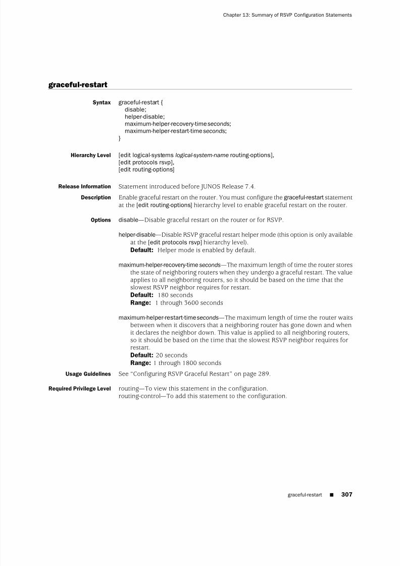
8/7/2019 Config Guide Mpls Applications
http://slidepdf.com/reader/full/config-guide-mpls-applications 345/547
graceful-restart
Syntax graceful-restart {disable;helper-disable;maximum-helper-recovery-time seconds;maximum-helper-restart-time seconds;
}
Hierarchy Level [edit logical-systems logical-system-name routing-options],[edit protocols rsvp],[edit routing-options]
Release Information Statement introduced before JUNOS Release 7.4.
Description Enable graceful restart on the router. You must configure the graceful-restart statementat the [edit routing-options] hierarchy level to enable graceful restart on the router.
Options disable—Disable graceful restart on the router or for RSVP.
helper-disable—Disable RSVP graceful restart helper mode (this option is only availableat the [edit protocols rsvp] hierarchy level).Default: Helper mode is enabled by default.
maximum-helper-recovery-time seconds—The maximum length of time the router storesthe state of neighboring routers when they undergo a graceful restart. The valueapplies to all neighboring routers, so it should be based on the time that theslowest RSVP neighbor requires for restart.
Default: 180 secondsRange: 1 through 3600 seconds
maximum-helper-restart-time seconds—The maximum length of time the router waitsbetween when it discovers that a neighboring router has gone down and whenit declares the neighbor down. This value is applied to all neighboring routers,so it should be based on the time that the slowest RSVP neighbor requires forrestart.Default: 20 secondsRange: 1 through 1800 seconds
Usage Guidelines See “Configuring RSVP Graceful Restart” on page 289.
Required Privilege Level routing—To view this statement in the configuration.
routing-control—
To add this statement to the configuration.
graceful-restart ■ 307
Chapter 13: Summary of RSVP Configuration Statements

8/7/2019 Config Guide Mpls Applications
http://slidepdf.com/reader/full/config-guide-mpls-applications 346/547
hello-interval
Syntax hello-interval seconds;
Hierarchy Level [edit logical-systems logical-system-name protocols rsvp interface interface-name],[edit logical-systems logical-system-name protocols rsvp
peer-interface peer-interface-name],[edit protocols rsvp interface interface-name],[edit protocols rsvp peer-interface peer-interface-name]
Release Information Statement introduced before JUNOS Release 7.4.
Description Enable the sending of hello packets on the interface.
Options seconds—Length of time between hello packets. A value of 0 disables the sending of
hello packets on the interface.Range: 1 through 60 secondsDefault: 9 seconds
Usage Guidelines See “Configuring the RSVP Hello Interval” on page 278.
Required Privilege Level routing—To view this statement in the configuration.routing-control—To add this statement to the configuration.
hop-limit
Syntax hop-limit number ;
Hierarchy Level [edit logical-systems logical-system-name protocols rsvp interface interface-name
link-protection],[edit logical-systems logical-system-name protocols rsvp interface interface-name
link-protection bypass bypass-name],[edit protocols rsvp interface interface-name link-protection],[edit protocols rsvp interface interface-name link-protection bypass bypass-name]
Release Information Statement introduced before JUNOS Release 7.4.
Description Specify the maximum number of hops a bypass can traverse. By default, each bypasscan traverse a maximum of 255 hops, including the ingress and egress routers.
Options number —Maximum number of hops a bypass can traverse.Range: 2 through 255 hopsDefault: 255 hops
Usage Guidelines See “Configuring the Hop Limit for Bypass LSPs” on page 285.
Required Privilege Level routing—To view this statement in the configuration.routing-control—To add this statement to the configuration.
308 ■ hello-interval
JUNOS 9.6 MPLS Applications Configuration Guide

8/7/2019 Config Guide Mpls Applications
http://slidepdf.com/reader/full/config-guide-mpls-applications 347/547
interface
Syntax interface interface-name {disable;(aggregate | no-aggregate);authentication-key key ;bandwidth bps;hello-interval seconds;link-protection {
disable;admin-group {
exclude [ group-names ];include-all [ group-names ];include-any [ group-names ];
}
bandwidth bps;bypass bypass-name {bandwidth bps {
ct0 bps;ct1 bps;ct2 bps;ct3 bps;
}class-of-service cos-value;hop-limit number ;no-cspf ;path address <strict | loose>;priority setup-priority reservation-priority ;to address;
}class-of-service cos-value;hop-limit number ;max-bypasses number ;no-cspf ;no-node-protection;optimize-timer seconds;path address <strict | loose>;priority setup-priority reservation-priority ;subscription percentage;
}(reliable | no-reliable);subscription percentage {
ct0 percentage;
ct1 percentage;ct2 percentage;ct3 percentage;
}update-threshold threshold;
}
Hierarchy Level [edit logical-systems logical-system-name protocols rsvp],[edit protocols rsvp]
interface ■ 309
Chapter 13: Summary of RSVP Configuration Statements

8/7/2019 Config Guide Mpls Applications
http://slidepdf.com/reader/full/config-guide-mpls-applications 348/547
Release Information Statement introduced before JUNOS Release 7.4.
Description Enable RSVP on one or more router interfaces.
Default RSVP is disabled on all interfaces.
Options interface-name—Name of an interface. To configure all interfaces, specify all. Fordetails about specifying interfaces, see the JUNOS Network Interfaces ConfigurationGuide.
The remaining statements are explained separately.
Usage Guidelines See “Minimum RSVP Configuration” on page 273.
Required Privilege Level routing—To view this statement in the configuration.routing-control—To add this statement to the configuration.
keep-multiplier
Syntax keep-multiplier number ;
Hierarchy Level [edit logical-systems logical-system-name protocols rsvp],[edit protocols rsvp]
Release Information Statement introduced before JUNOS Release 7.4.
Description Set the keep multiplier value.
Options number —Multiplier value.Range: 1 through 255Default: 3
Usage Guidelines See “Configuring Timers for RSVP Refresh Messages” on page 292.
Required Privilege Level routing—To view this statement in the configuration.routing-control—To add this statement to the configuration.
310 ■ keep-multiplier
JUNOS 9.6 MPLS Applications Configuration Guide

8/7/2019 Config Guide Mpls Applications
http://slidepdf.com/reader/full/config-guide-mpls-applications 349/547
link-protection (RSVP)
Syntax link-protection {disable;admin-group {
exclude [ group-names ];include-all [ group-names ];include-any [ group-names ];
}bandwidth bps;bypass bypass-name {
bandwidth bps {ct0 bps;ct1 bps;ct2 bps;
ct3 bps;}class-of-service cos-value;hop-limit number ;no-cspf ;path address <strict | loose>;priority setup-priority reservation-priority ;to address;
}class-of-service cos-value;hop-limit number ;max-bypasses number ;no-cspf ;no-node-protection;
optimize-timer seconds;path address <strict | loose>;priority setup-priority reservation-priority ;subscription percentage;
}
Hierarchy Level [edit logical-systems logical-system-name protocols rsvp interface interface-name],[edit protocols rsvp interface interface-name]
Release Information Statement introduced before JUNOS Release 7.4.
Description Enable link protection on the specified interface. Using link protection, you canconfigure a network to reroute traffic quickly around broken links. To fully enablelink protection, you also need to configure the link-protection statement at the [editprotocols mpls label-switched-path lsp-name] hierarchy level. You can configure singleor multiple bypasses for protected interface.
Default Link protection is disabled.
Options no-node-protection—Disables node-link protection on the RSVP interface. Linkprotection remains active. When this option is configured, the router can onlyinitiate a next-hop bypass, not a next-next-hop bypass.
link-protection (RSVP) ■ 311
Chapter 13: Summary of RSVP Configuration Statements
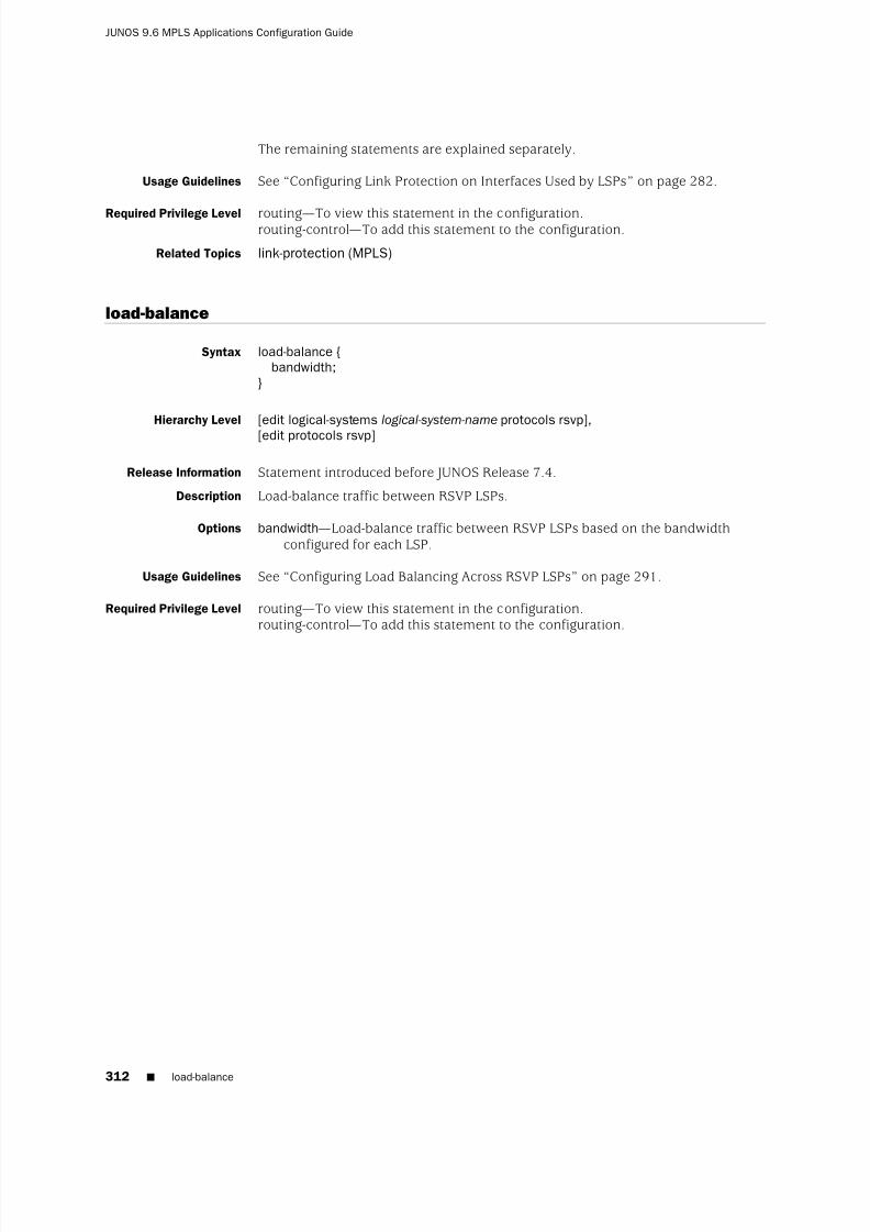
8/7/2019 Config Guide Mpls Applications
http://slidepdf.com/reader/full/config-guide-mpls-applications 350/547
The remaining statements are explained separately.
Usage Guidelines See “Configuring Link Protection on Interfaces Used by LSPs” on page 282.
Required Privilege Level routing—
To view this statement in the configuration.routing-control—To add this statement to the configuration.
Related Topics link-protection (MPLS)
load-balance
Syntax load-balance {bandwidth;
}
Hierarchy Level [edit logical-systems logical-system-name protocols rsvp],
[edit protocols rsvp]
Release Information Statement introduced before JUNOS Release 7.4.
Description Load-balance traffic between RSVP LSPs.
Options bandwidth—Load-balance traffic between RSVP LSPs based on the bandwidthconfigured for each LSP.
Usage Guidelines See “Configuring Load Balancing Across RSVP LSPs” on page 291.
Required Privilege Level routing—To view this statement in the configuration.routing-control—To add this statement to the configuration.
312 ■ load-balance
JUNOS 9.6 MPLS Applications Configuration Guide

8/7/2019 Config Guide Mpls Applications
http://slidepdf.com/reader/full/config-guide-mpls-applications 351/547
max-bypasses
Syntax max-bypasses number ;
Hierarchy Level [edit logical-systems logical-system-name protocols rsvp interface interface-name],[edit protocols rsvp interface interface-name]
Release Information Statement introduced before JUNOS Release 7.4. Range modified in JUNOSRelease 9.3.
Description Specify the maximum number of dynamic bypass LSPs permitted for protecting thisinterface. When this option is configured, multiple bypasses for link protection areenabled. Call admission control (CAC) is also enabled. The limit on bypassesconfigured applies only to dynamically generated bypass LSPs. By default, this optionis disabled and only one dynamic bypass LSP is enabled for each interface. If you
configure max-bypasses, you must also configure the bandwidth statement.
Options number—Configure the maximum number of bypass LSPs. If you configure a valueof 0, no dynamic bypass LSPs are allowed to be established for the interface.Only static bypass LSPs can be configured.Default: 1Range: 0 through 99
Usage Guidelines See “Configuring the Maximum Number of Bypass LSPs” on page 286.
Required Privilege Level routing—To view this statement in the configuration.routing-control—To add this statement to the configuration.
no-adjacency-down-notification
Syntax no-adjacency-down-notification;
Hierarchy Level [edit logical-systems logical-system-name protocols isis interface interface-name],[edit protocols isis interface interface-name]
Release Information Statement introduced in JUNOS Release 8.0.
Description Disables adjacency down notification for IS-IS to allow for migration from IS-IS toOSPF without disruption of the RSVP neighbors and associated RSVP-signaled LSPs.
Usage Guidelines
See“
Disabling Adjacency Down and Neighbor Down Notification in IS-IS and OSPF”
on page 295.
Required Privilege Level routing—To view this statement in the configuration.routing-control—To add this statement to the configuration.
max-bypasses ■ 313
Chapter 13: Summary of RSVP Configuration Statements

8/7/2019 Config Guide Mpls Applications
http://slidepdf.com/reader/full/config-guide-mpls-applications 352/547
no-aggregate
See aggregate.
no-cspf
Syntax no-cspf;
Hierarchy Level [edit logical-systems logical-system-name protocols rsvp interface interface-name
link-protection],[edit logical-systems logical-system-name protocols rsvp interface interface-name
link-protection bypass bypass-name],[edit protocols rsvp interface interface-name link-protection],
[edit protocols rsvp interface interface-name link-protection bypass bypass-name]
Release Information Statement introduced in JUNOS Release 7.5.
Description Disable CSPF computation on all bypass LSPs or on a specific bypass LSP. You needto disable CSPF for link protection to function properly on interarea paths.
Default CSPF is enabled.
Usage Guidelines See “Disabling CSPF for Bypass LSPs” on page 287.
Required Privilege Level routing—To view this statement in the configuration.routing-control—To add this statement to the configuration.
no-neighbor-down-notification
Syntax no-neighbor-down-notification;
Hierarchy Level [edit logical-systems logical-system-name protocols ospf area area-id interfaceinterface-name],
[edit protocols ospf area area-id interface interface-name]
Release Information Statement introduced in JUNOS Release 8.0.
Description Disables neighbor down notification for OSPF to allow for migration from OSPF toIS-IS without disruption of the RSVP neighbors and associated RSVP-signaled LSPs.
Usage Guidelines See “Disabling Adjacency Down and Neighbor Down Notification in IS-IS and OSPF”on page 295.
Required Privilege Level routing—To view this statement in the configuration.routing-control—To add this statement to the configuration.
314 ■ no-aggregate
JUNOS 9.6 MPLS Applications Configuration Guide

8/7/2019 Config Guide Mpls Applications
http://slidepdf.com/reader/full/config-guide-mpls-applications 353/547
no-node-id-subobject
Syntax no-node-id-subobject;
Hierarchy Level [edit logical-systems logical-system-name protocols rsvp],[edit protocols rsvp]
Release Information Statement introduced in JUNOS Release 9.4.
Description Disables the record route object (RRO) node ID subobject for compatibility withearlier versions of the JUNOS Software. To interoperate with other vendors’equipment, the JUNOS Software supports the RRO node ID subobject for use ininter-AS link and node protection configurations.
Usage Guidelines See “Configuring Inter-AS Node and Link Protection” on page 281.
Required Privilege Level routing—To view this statement in the configuration.routing-control—To add this statement to the configuration.
no-p2mp-sublsp
Syntax no-p2mp-sublsp;
Hierarchy Level [edit logical-systems logical-system-name protocols rsvp],[edit protocols rsvp]
Release Information Statement introduced in JUNOS Release 9.2.Description Rejects Resv messages that include the S2L_SUB_LSP object. By default, Resv
messages which include the S2L_SUB_LSP object are accepted. However, in a networkwhich includes Juniper Networks devices running both JUNOS 9.2 and later releasesand JUNOS 9.1 and earlier releases, it is necessary to configure the no-p2mp-sublspstatement on the JUNOS 9.2 and later devices to ensure that P2MP LSPs functionproperly.
Default Resv messages which include the S2L_SUB_LSP object are accepted.
Usage Guidelines See “Preserving Point-to-Multipoint LSP Functioning with Different JUNOS SoftwareReleases” on page 147.
Required Privilege Level routing—
To view this statement in the configuration.routing-control—To add this statement to the configuration.
no-reliable
See reliable
no-node-id-subobject ■ 315
Chapter 13: Summary of RSVP Configuration Statements

8/7/2019 Config Guide Mpls Applications
http://slidepdf.com/reader/full/config-guide-mpls-applications 354/547
node-link-protection
Syntax node-link-protection;
Hierarchy Level [edit logical-systems logical-system-name protocols mpls label-switched-path lsp-name],[edit protocols mpls label-switched-path lsp-name]
Release Information Statement introduced before JUNOS Release 7.4.
Description Enable node and link protection on the specified LSP. To fully enable node and linkprotection, you also need to include the link-protection statement at the [edit protocolsrsvp interface interface-name] hierarchy level.
Default Node and link protection is disabled.
Usage Guidelines See “Configuring Node Protection or Link Protection for LSPs” on page 281.
Required Privilege Level routing—To view this statement in the configuration.routing-control—To add this statement to the configuration.
optimize-timer
Syntax optimize-timer seconds;
Hierarchy Level [edit logical-systems logical-system-name protocols rsvp interface interface-name
link-protection],[edit protocols rsvp interface interface-name link-protection]
Release Information Statement introduced before JUNOS Release 7.4.
Description Configure an optimize timer for a bypass LSP. The optimize timer initiates a periodicoptimization process that reshuffles data LSPs among bypass LSPs to achieve themost efficient use of network resources. The optimization process attempts to eitherminimize the number of bypasses currently in use, minimize the total amount of bandwidth reserved for all bypasses, or both.
Options seconds—Specify the number of seconds between optimizations.Range: 0 through 65,535 secondsDefault: 0 (disabled)
Usage Guidelines See “Configuring the Optimization Interval for Bypass LSPs” on page 287.
Required Privilege Level routing—To view this statement in the configuration.routing-control—To add this statement to the configuration.
316 ■ node-link-protection
JUNOS 9.6 MPLS Applications Configuration Guide

8/7/2019 Config Guide Mpls Applications
http://slidepdf.com/reader/full/config-guide-mpls-applications 355/547
path
Syntax path address <strict | loose>;
Hierarchy Level [edit logical-systems logical-system-name protocols rsvp interface interface-name
link-protection],[edit logical-systems logical-system-name protocols rsvp interface interface-name
link-protection bypass bypass-name],[edit protocols rsvp interface interface-name link-protection],[edit protocols rsvp interface interface-name link-protection bypass bypass-name]
Release Information Statement introduced before JUNOS Release 7.4.
Description Configure an explicit path (a sequence of strict or loose routes) to control where andhow a bypass LSP is established. If multiple bypasses are configured, they all will
use the same explicit path.
Default No path is configured. CSPF automatically calculates the path the bypass LSP takes.
Options address—IP address of each transit router in the LSP. You must specify the addressor hostname of each transit router, although you do not need to list each transitrouter if its type is loose. As an option, you can include the ingress and egressrouters in the path. Specify the addresses in order, starting with the ingress router(optional) or the first transit router, and continuing sequentially along the pathuntil reaching the egress router (optional) or the router immediately before theegress router.Default: If you do not specify any routers explicitly, no routing limitations areimposed on the bypass LSP.
loose—The next address in the path statement is loose. The LSP can traverse otherrouters before reaching this router.Default: strict
strict—The LSP must go to the next address specified in the path statement withouttraversing other nodes. This is the default.
Usage Guidelines See “Configuring an Explicit Path for Bypass LSPs” on page 288.
Required Privilege Level routing—To view this statement in the configuration.routing-control—To add this statement to the configuration.
path ■ 317
Chapter 13: Summary of RSVP Configuration Statements

8/7/2019 Config Guide Mpls Applications
http://slidepdf.com/reader/full/config-guide-mpls-applications 356/547
peer-interface
Syntax peer-interface peer-interface-name {disable;(aggregate | no-aggregate);authentication-key key ;hello-interval seconds;(reliable | no-reliable);
}
Hierarchy Level [edit logical-systems logical-system-name protocols rsvp],[edit protocols rsvp]
Release Information Statement introduced before JUNOS Release 7.4.
Description Configure the name of the LMP peer device.
The remaining statements are explained separately.
Options The options are explained separately.
Usage Guidelines See “Configuring RSVP and OSPF for LMP Peer Interfaces” on page 457.
Required Privilege Level routing—To view this statement in the configuration.routing-control—To add this statement to the configuration.
318 ■ peer-interface
JUNOS 9.6 MPLS Applications Configuration Guide

8/7/2019 Config Guide Mpls Applications
http://slidepdf.com/reader/full/config-guide-mpls-applications 357/547
preemption
Syntax preemption {(aggressive | disabled | normal);soft-preemption {
cleanup-timer seconds;}
}
Hierarchy Level [edit logical-systems logical-system-name protocols rsvp],[edit protocols rsvp]
Release Information Statement introduced before JUNOS Release 7.4.
Description Control RSVP session preemption.
Default normal
Options aggressive—Preempt RSVP sessions whenever bandwidth is insufficient to handleall sessions. A session is preempted whenever bandwidth is lowered or a newhigher-priority session is established.
disabled—Do not preempt RSVP sessions.
normal—Preempt RSVP sessions to accommodate new higher-priority sessions whenbandwidth is insufficient to handle all sessions.
The remaining statements are explained separately.
Usage Guidelines See “Preempting RSVP Sessions” on page 293.
Required Privilege Level routing—To view this statement in the configuration.routing-control—To add this statement to the configuration.
preemption ■ 319
Chapter 13: Summary of RSVP Configuration Statements

8/7/2019 Config Guide Mpls Applications
http://slidepdf.com/reader/full/config-guide-mpls-applications 358/547
priority
Syntax priority setup-priority reservation-priority ;
Hierarchy Level [edit logical-systems logical-system-name protocols rsvp interface interface-name
link-protection],[edit logical-systems logical-system-name protocols rsvp interface interface-name
link-protection bypass bypass-name],[edit protocols rsvp interface interface-name link-protection],[edit protocols rsvp interface interface-name link-protection bypass bypass-name],
Release Information Statement introduced before JUNOS Release 7.4.
Description Configure the setup priority and reservation priority for a bypass LSP. If insufficientlink bandwidth is available during session establishment, the setup priority is
compared with other setup priorities for established sessions on the link to determinewhether some of them should be preempted to accommodate the new session. Thesession with the lower-hold priority is preempted.
Options reservation-priority —Reservation priority, used to keep a reservation after it has beenset up. A smaller number has a higher priority. The priority must be greater thanor equal to the setup priority to prevent preemption loops.Range: 0 through 7, where 0 is the highest and 7 is the lowest priority.Default: 0 (Once the session is set up, no other session can preempt it.)
setup-priority —Setup priority.Range: 0 through 7, where 0 is the highest and 7 is the lowest priority.Default: 7 (The session cannot preempt any existing sessions.)
Usage Guidelines See “Configuring Priority and Preemption for Bypass LSPs” on page 289 and“Configuring Priority and Preemption for LSPs” on page 102.
Required Privilege Level routing—To view this statement in the configuration.routing-control—To add this statement to the configuration.
320 ■ priority
JUNOS 9.6 MPLS Applications Configuration Guide
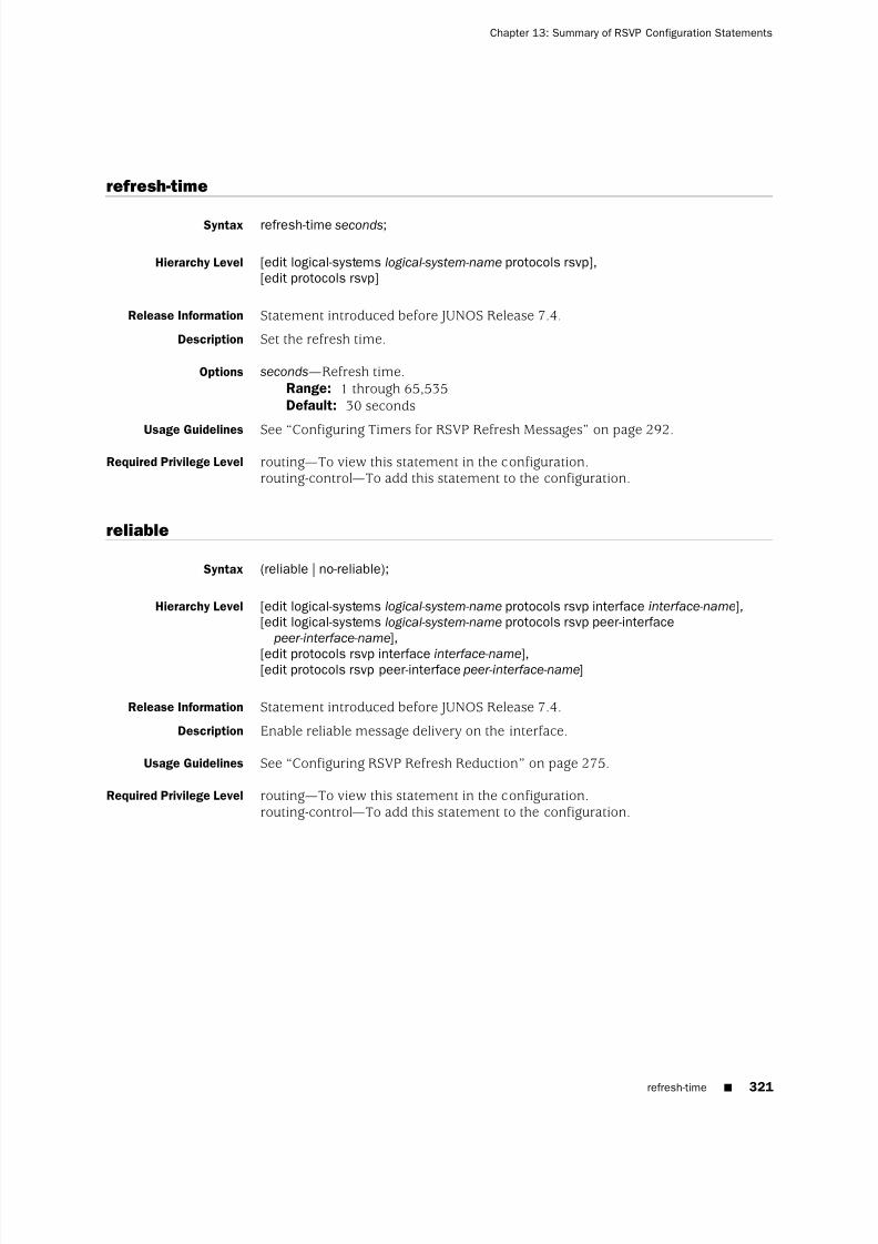
8/7/2019 Config Guide Mpls Applications
http://slidepdf.com/reader/full/config-guide-mpls-applications 359/547
refresh-time
Syntax refresh-time seconds;
Hierarchy Level [edit logical-systems logical-system-name protocols rsvp],[edit protocols rsvp]
Release Information Statement introduced before JUNOS Release 7.4.
Description Set the refresh time.
Options seconds—Refresh time.Range: 1 through 65,535Default: 30 seconds
Usage Guidelines See“
Configuring Timers for RSVP Refresh Messages”
on page 292.Required Privilege Level routing—To view this statement in the configuration.
routing-control—To add this statement to the configuration.
reliable
Syntax (reliable | no-reliable);
Hierarchy Level [edit logical-systems logical-system-name protocols rsvp interface interface-name],[edit logical-systems logical-system-name protocols rsvp peer-interface
peer-interface-name],
[edit protocols rsvp interface interface-name],[edit protocols rsvp peer-interface peer-interface-name]
Release Information Statement introduced before JUNOS Release 7.4.
Description Enable reliable message delivery on the interface.
Usage Guidelines See “Configuring RSVP Refresh Reduction” on page 275.
Required Privilege Level routing—To view this statement in the configuration.routing-control—To add this statement to the configuration.
refresh-time ■ 321
Chapter 13: Summary of RSVP Configuration Statements

8/7/2019 Config Guide Mpls Applications
http://slidepdf.com/reader/full/config-guide-mpls-applications 360/547

8/7/2019 Config Guide Mpls Applications
http://slidepdf.com/reader/full/config-guide-mpls-applications 361/547
subscription
Syntax subscription percentage {ct0 percentage;ct1 percentage;ct2 percentage;ct3 percentage;
}
Hierarchy Level [edit logical-systems logical-system-name protocols rsvp interface interface-name],[edit logical-systems logical-system-name protocols rsvp interface interface-name
link-protection],[edit protocols rsvp interface interface-name],[edit protocols rsvp interface interface-name link-protection]
Release Information Statement introduced before JUNOS Release 7.4.
Description Configures the amount of bandwidth subscribed to a class type (when you haveenabled Differentiated Services), or bypass LSP (when you have enabled linkprotection). The subscription is the percentage of the link bandwidth that can beused for the RSVP reservation process.
Options ctnumber percentage—Percent of the class-type bandwidth that RSVP allows to beused for reservations. If you specify a value greater than 100, you areoversubscribing the class type. You can specify bandwidth subscriptions for classtypes 0 through 3. This option is not available for bypass LSPs.Range: 0 through 65,000Default: 100 percent
percentage—Percent of the class-type or bypass LSP bandwidth that RSVP allows tobe used for reservations. If you specify a value greater than 100, you areoversubscribing the class type or bypass LSP.Range: 0 through 65,000Default: 100 percent
Usage Guidelines See “Configuring the Bandwidth Subscription Percentage for LSPs” on page 124 and“Configuring the Amount of Bandwidth Subscribed for Bypass LSPs” on page 288.
Required Privilege Level routing—To view this statement in the configuration.routing-control—To add this statement to the configuration.
subscription ■ 323
Chapter 13: Summary of RSVP Configuration Statements

8/7/2019 Config Guide Mpls Applications
http://slidepdf.com/reader/full/config-guide-mpls-applications 362/547
traceoptions
Syntax traceoptions {file filename <files number > <size size> <world-readable | no-world-readable>;flag flag <flag-modifier > <disable>;
}
Hierarchy Level [edit logical-systems logical-system-name protocols rsvp],[edit protocols rsvp]
Release Information Statement introduced before JUNOS Release 7.4.
Description Enable RSVP-level trace options.
Default The default RSVP-level trace options are those inherited from the routing protocols
traceoptions statement included at the [edit routing-options] hierarchy level.
Options disable—(Optional) Disable the tracing operation. You can use this option to disablea single operation when you have defined a broad group of tracing operations,such as all.
filename—Name of the file to receive the output of the tracing operation. Enclose thename within quotation marks. All files are placed in the directory /var/log. Werecommend that you place RSVP tracing output in the file rsvp-log.
files number —(Optional) Maximum number of trace files. When a trace file namedtrace-file reaches its maximum size, it is renamed trace-file.0, then trace-file.1,and so on, until the maximum number of trace files is reached. Then the oldest
trace file is overwritten.Range: 2 through 1000Default: 2 files
If you specify a maximum number of files, you must also include the size statementto specify the maximum file size.
flag —Tracing operation to perform. To specify more than one tracing operation,include multiple flag statements.
■ all—All tracing operations
■ error—All detected error conditions
■ event—RSVP-related events
■ lmp—RSVP-LMP interactions
■ packets—All RSVP packets
■ path—All path messages
■ pathtear—PathTear messages
■ resv—Resv messages
■ resvtear—ResvTear messages
324 ■ traceoptions
JUNOS 9.6 MPLS Applications Configuration Guide

8/7/2019 Config Guide Mpls Applications
http://slidepdf.com/reader/full/config-guide-mpls-applications 363/547
■ route—Routing information
■ state—Session state transitions
flag-modifier —(Optional) Modifier for the tracing flag. You can specify one or moreof these modifiers:
■ detail—Provide detailed trace information
■ receive—Packets being received
■ send—Packets being transmitted
no-world-readable—(Optional) Enable only certain users to read the log file.
size size—(Optional) Maximum size of each trace file, in kilobytes (KB), megabytes(MB), or gigabytes (GB). When a trace file named trace-file reaches this size, it isrenamed trace-file.0. When the trace-file again reaches this size, trace-file.0 is
renamed trace-file.1 and trace-file is renamed trace-file.0. This renaming schemecontinues until the maximum number of trace files is reached. Then the oldesttrace file is overwritten.Syntax: xk to specify KB, xm to specify MB, or xg to specify GBRange: 10 KB through the maximum file size supported on your systemDefault: 1 MB
If you specify a maximum file size, you must also include the files statement tospecify the maximum number of files.
world-readable—(Optional) Enable any user to read the log file.
Usage Guidelines See “Tracing RSVP Protocol Traffic” on page 297.
Required Privilege Level routing and trace—To view this statement in the configuration.routing-control and trace-control—To add this statement to the configuration.
traceoptions ■ 325
Chapter 13: Summary of RSVP Configuration Statements

8/7/2019 Config Guide Mpls Applications
http://slidepdf.com/reader/full/config-guide-mpls-applications 364/547
tunnel-services
Syntax tunnel-services {devices device-names;
}
Hierarchy Level [edit protocols rsvp]
Release Information Statement introduced in JUNOS Release 8.1.
Description Enables ultimate-hop popping on point-to-multipoint LSPs. The JUNOS Softwareselects one of the available virtual tunnel (VT) interfaces to de-encapsulate the egresstraffic. By default, the selection process is performed automatically.
Default Ultimate-hop popping is disabled.
Options devices device-names—Specifies which VT interfaces are used to handle the RSVPtraffic.Range: 0 to 8 devices
Usage Guidelines See “Enabling Ultimate-Hop Popping on Point-to-Multipoint LSPs” on page 296.
Required Privilege Level routing—To view this statement in the configuration.routing-control—To add this statement to the configuration.
update-threshold
Syntax update-threshold threshold;
Hierarchy Level [edit logical-systems logical-system-name protocols rsvp interface interface-name],[edit protocols rsvp interface interface-name]
Release Information Statement introduced before JUNOS Release 7.4.
Description Adjust the threshold at which a change in bandwidth triggers an interior gatewayprotocol (IGP) update.
Options threshold—Specifies the percentage change in bandwidth to trigger an IGP update.Range: 1 through 20 percentDefault: 10 percent
Usage Guidelines See“Configuring the RSVP Update Threshold on an Interface
”on page 279.
Required Privilege Level routing—To view this statement in the configuration.routing-control—To add this statement to the configuration.
326 ■ tunnel-services
JUNOS 9.6 MPLS Applications Configuration Guide

8/7/2019 Config Guide Mpls Applications
http://slidepdf.com/reader/full/config-guide-mpls-applications 365/547
Part 4
LDP
■ LDP Overview on page 329
■ LDP Configuration Guidelines on page 337
■ Summary of LDP Configuration Statements on page 367
LDP ■ 327

8/7/2019 Config Guide Mpls Applications
http://slidepdf.com/reader/full/config-guide-mpls-applications 366/547
328 ■ LDP
JUNOS 9.6 MPLS Applications Configuration Guide

8/7/2019 Config Guide Mpls Applications
http://slidepdf.com/reader/full/config-guide-mpls-applications 367/547
Chapter 14
LDP Overview
This chapter discusses the following topics:
■ LDP Introduction on page 329
■ LDP Standards on page 330
■ JUNOS Software LDP Protocol Implementation on page 330
■ LDP Operation on page 331
■ Tunneling LDP LSPs in RSVP LSPs on page 331
■ Tunneling LDP LSPs in RSVP LSPs Overview on page 331
■ Label Operations on page 332
■ LDP Message Types on page 333
■ Discovery Messages on page 333
■ Session Messages on page 334
■ Advertisement Messages on page 334
■ Notification Messages on page 334
■ LDP Graceful Restart on page 334
LDP Introduction
The Label Distribution Protocol (LDP) is a protocol for distributing labels innon-traffic-engineered applications. LDP allows routers to establish label-switchedpaths (LSPs) through a network by mapping network-layer routing information directlyto data link layer-switched paths.
These LSPs might have an endpoint at a directly attached neighbor (comparable toIP hop-by-hop forwarding), or at a network egress node, enabling switching throughall intermediary nodes. LSPs established by LDP can also traverse traffic-engineered
LSPs created by RSVP.
LDP associates a forwarding equivalence class (FEC) with each LSP it creates. TheFEC associated with an LSP specifies which packets are mapped to that LSP. LSPsare extended through a network as each router chooses the label advertised by thenext hop for the FEC and splices it to the label it advertises to all other routers. Thisprocess forms a tree of LSPs that converge on the egress router.
LDP Introduction ■ 329
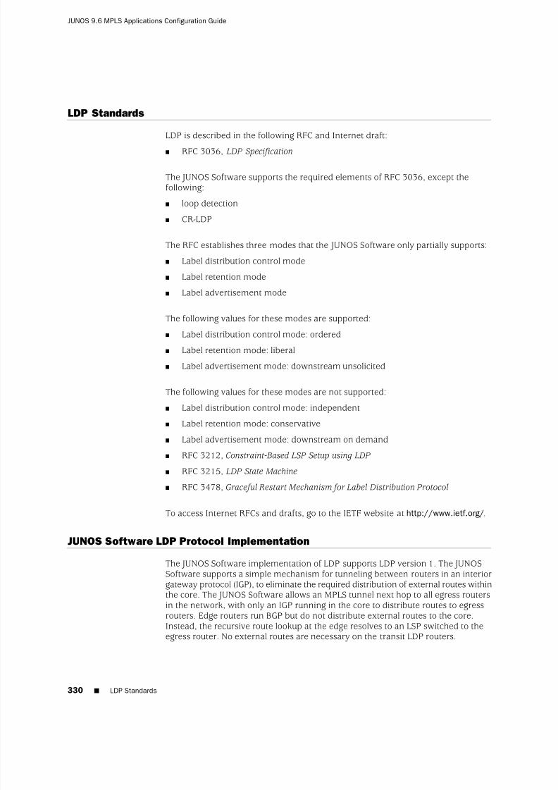
8/7/2019 Config Guide Mpls Applications
http://slidepdf.com/reader/full/config-guide-mpls-applications 368/547
LDP Standards
LDP is described in the following RFC and Internet draft:■ RFC 3036, LDP Specification
The JUNOS Software supports the required elements of RFC 3036, except thefollowing:
■ loop detection
■ CR-LDP
The RFC establishes three modes that the JUNOS Software only partially supports:
■ Label distribution control mode
■ Label retention mode■ Label advertisement mode
The following values for these modes are supported:
■ Label distribution control mode: ordered
■ Label retention mode: liberal
■ Label advertisement mode: downstream unsolicited
The following values for these modes are not supported:
■ Label distribution control mode: independent
■ Label retention mode: conservative
■ Label advertisement mode: downstream on demand
■ RFC 3212, Constraint-Based LSP Setup using LDP
■ RFC 3215, LDP State Machine
■ RFC 3478, Graceful Restart Mechanism for Label Distribution Protocol
To access Internet RFCs and drafts, go to the IETF website at http://www.ietf.org/.
JUNOS Software LDP Protocol Implementation
The JUNOS Software implementation of LDP supports LDP version 1. The JUNOSSoftware supports a simple mechanism for tunneling between routers in an interiorgateway protocol (IGP), to eliminate the required distribution of external routes withinthe core. The JUNOS Software allows an MPLS tunnel next hop to all egress routersin the network, with only an IGP running in the core to distribute routes to egressrouters. Edge routers run BGP but do not distribute external routes to the core.Instead, the recursive route lookup at the edge resolves to an LSP switched to theegress router. No external routes are necessary on the transit LDP routers.
330 ■ LDP Standards
JUNOS 9.6 MPLS Applications Configuration Guide

8/7/2019 Config Guide Mpls Applications
http://slidepdf.com/reader/full/config-guide-mpls-applications 369/547
LDP Operation
You must configure LDP for each interface on which you want LDP to run. LDPcreates LSP trees rooted at each egress router for the router ID address that is thesubsequent BGP next hop. The ingress point is at every router running LDP. Thisprocess provides an inet.3 route to every egress router. If BGP is running, it willattempt to resolve next hops by using the inet.3 table first, which binds most, if notall, of the BGP routes to MPLS tunnel next hops.
Two adjacent routers running LDP become neighbors. If the two routers are connectedby more than one interface, they become neighbors on each interface. When LDProuters become neighbors, they establish an LDP session to exchange labelinformation. If per-router labels are in use on both routers, only one LDP session isestablished between them, even if they are neighbors on multiple interfaces. For thisreason, an LDP session is not related to a particular interface.
LDP operates in conjunction with a unicast routing protocol. LDP installs LSPs onlywhen both LDP and the routing protocol are enabled. For this reason, you mustenable both LDP and the routing protocol on the same set of interfaces. If this is notdone, LSPs might not be established between each egress router and all ingressrouters, which might result in loss of BGP-routed traffic.
You can apply policy filters to labels received from and distributed to other routersthrough LDP. Policy filters provide you with a mechanism to control the establishmentof LSPs.
For LDP to run on an interface, MPLS must be enabled on a logical interface on thatinterface. For more information, see the JUNOS Network Interfaces ConfigurationGuide.
Tunneling LDP LSPs in RSVP LSPs
You can tunnel LDP LSPs over RSVP LSPs. The following sections describe howtunneling of LDP LSPs in RSVP LSPs works:
■ Tunneling LDP LSPs in RSVP LSPs Overview on page 331
■ Label Operations on page 332
Tunneling LDP LSPs in RSVP LSPs Overview
If you are using RSVP for traffic engineering, you can run LDP simultaneously toeliminate the distribution of external routes in the core. The LSPs established by LDPare tunneled through the LSPs established by RSVP. LDP effectively treats thetraffic-engineered LSPs as single hops.
When you configure the router to run LDP across RSVP-established LSPs, LDPautomatically establishes sessions with the router at the other end of the LSP. LDPcontrol packets are routed hop-by-hop, rather than carried through the LSP. Thisrouting allows you to use simplex (one-way) traffic-engineered LSPs. Traffic in the
LDP Operation ■ 331
Chapter 14: LDP Overview

8/7/2019 Config Guide Mpls Applications
http://slidepdf.com/reader/full/config-guide-mpls-applications 370/547
opposite direction flows through LDP-established LSPs that follow unicast routingrather than through traffic-engineered tunnels.
If you configure LDP over RSVP LSPs, you can still configure multiple OSPF areas
and IS-IS levels in the traffic engineered core and in the surrounding LDP cloud.
Label Operations
Figure 23 on page 332 depicts an LDP LSP being tunneled through an RSVP LSP. (Fordefinitions of label operations, see “Label Description” on page 25.) The shadedinner oval represents the RSVP domain, whereas the outer oval depicts the LDPdomain. RSVP establishes an LSP through routers B, C, D, and E, with the sequenceof labels L3, L4. LDP establishes an LSP through Routers A, B, E, F, and G, with thesequence of labels L1, L2, L5. LDP views the RSVP LSP between Routers B and E asa single hop.
When the packet arrives at Router A, it enters the LSP established by LDP, and alabel (L1) is pushed onto the packet. When the packet arrives at Router B, the label(L1) is swapped with another label (L2). Because the packet is entering thetraffic-engineered LSP established by RSVP, a second label (L3) is pushed onto thepacket.
This outer label (L3) is swapped with a new label (L4) at the intermediate router (C)within the RSVP LSP tunnel, and when the penultimate router (D) is reached, the toplabel is popped. Router E swaps the label (L2) with a new label (L5), and thepenultimate router for the LDP-established LSP (F) pops the last label.
Figure 23: Swap and Push When LDP LSPs Are Tunneled Through RSVP LSPs
Figure 24 on page 333 depicts double push label operation (L1L2), which is used whenthe ingress router (A) of the LDP and the RSVP LSPs are the same router. Note thatRouter D is the penultimate hop for the LDP-established LSP, so L2 is popped fromthe packet by Router D.
332 ■ Label Operations
JUNOS 9.6 MPLS Applications Configuration Guide

8/7/2019 Config Guide Mpls Applications
http://slidepdf.com/reader/full/config-guide-mpls-applications 371/547
Figure 24: Double Push When LDP LSPs Are Tunneled Through RSVP LSPs
LDP Message Types
LDP uses the message types described in the following sections to establish andremove mappings and to report errors. All LDP messages have a common structurethat uses a type, length, and value (TLV) encoding scheme.
■ Discovery Messages on page 333
■ Session Messages on page 334
■ Advertisement Messages on page 334
■ Notification Messages on page 334
Discovery Messages
Discovery messages announce and maintain the presence of a router in a network.Routers indicate their presence in a network by sending hello messages periodically.Hello messages are transmitted as UDP packets to the LDP port at the group multicastaddress for all routers on the subnet.
LDP uses the following discovery procedures:
■ Basic discovery—A router periodically sends LDP link hello messages throughan interface. LDP link hello messages are sent as UDP packets addressed to theLDP discovery port. Receipt of an LDP link hello message on an interface identifies
an adjacency with the LDP peer router.■ Extended discovery—LDP sessions between routers not directly connected are
supported by LDP extended discovery. A router periodically sends LDP targetedhello messages to a specific address. Targeted hello messages are sent as UDPpackets addressed to the LDP discovery port at the specific address. The targetedrouter decides whether to respond to or ignore the targeted hello message. Atargeted router that chooses to respond does so by periodically sending targetedhello messages to the initiating router.
LDP Message Types ■ 333
Chapter 14: LDP Overview

8/7/2019 Config Guide Mpls Applications
http://slidepdf.com/reader/full/config-guide-mpls-applications 372/547
Session Messages
Session messages establish, maintain, and terminate sessions between LDP peers.When a router establishes a session with another router learned through the hellomessage, it uses the LDP initialization procedure over TCP transport. When theinitialization procedure is completed successfully, the two routers are LDP peers andcan exchange advertisement messages.
Advertisement Messages
Advertisement messages create, change, and delete label mappings for FECs.Requesting a label or advertising a label mapping to a peer is a decision made bythe local router. In general, the router requests a label mapping from a neighboringrouter when it needs one and advertises a label mapping to a neighboring routerwhen it wants the neighbor to use a label.
Notification Messages
Notification messages provide advisory information and signal error information.LDP sends notification messages to report errors and other events of interest. Thereare two kinds of LDP notification messages:
■ Error notifications, which signal fatal errors. If a router receives an errornotification from a peer for an LDP session, it terminates the LDP session byclosing the TCP transport connection for the session and discarding all labelmappings learned through the session.
■ Advisory notifications, which pass information to a router about the LDP session
or the status of some previous message received from the peer.
LDP Graceful Restart
LDP graceful restart enables a router whose LDP control plane is undergoing a restartto continue to forward traffic while recovering its state from neighboring routers. Italso enables a router on which helper mode is enabled to assist a neighboring routerthat is attempting to restart LDP.
During session initialization, a router advertises its ability to perform LDP gracefulrestart or to take advantage of a neighbor performing LDP graceful restart by sendingthe graceful restart TLV. This TLV contains two fields relevant to LDP graceful restart:
the reconnect time and the recovery time. The values of the reconnect and recoverytimes indicate the graceful restart capabilities supported by the router.
The reconnect time is configured in the JUNOS Software as 60 seconds and is notuser-configurable. When a router discovers that a neighboring router is restarting, itwaits until the end of the recovery time before attempting to reconnect. The recoverytime is the length of time a router waits for LDP to restart gracefully. The recoverytime period begins when an initialization message is sent or received. This timeperiod is also typically the length of time that a neighboring router maintains itsinformation about the restarting router, allowing it to continue to forward traffic.
334 ■ Session Messages
JUNOS 9.6 MPLS Applications Configuration Guide

8/7/2019 Config Guide Mpls Applications
http://slidepdf.com/reader/full/config-guide-mpls-applications 373/547
You can configure LDP graceful restart in both the master instance for the LDPprotocol and for a specific routing instance. You can disable graceful restart at theglobal level for all protocols, at the protocol level for LDP only, and on a specificrouting instance. LDP graceful restart is disabled by default, because at the global
level, graceful restart is disabled by default. However, helper mode (the ability toassist a neighboring router attempting a graceful restart) is enabled by default.
The following are some of the behaviors associated with LDP graceful restart:
■ Outgoing labels are not maintained in restarts. New outgoing labels are allocated.
■ When a router is restarting, no label-map messages are sent to neighbors thatsupport graceful restart until the restarting router has stabilized (label-mapmessages are immediately sent to neighbors that do not support graceful restart).However, all other messages (keepalive, address-message, notification, andrelease) are sent as usual. Distributing these other messages prevents the routerfrom distributing incomplete information.
■ Helper mode and graceful restart are independent. You can disable graceful
restart in the configuration, but still allow the router to cooperate with a neighborattempting to restart gracefully.
LDP Graceful Restart ■ 335
Chapter 14: LDP Overview

8/7/2019 Config Guide Mpls Applications
http://slidepdf.com/reader/full/config-guide-mpls-applications 374/547
336 ■ LDP Graceful Restart
JUNOS 9.6 MPLS Applications Configuration Guide

8/7/2019 Config Guide Mpls Applications
http://slidepdf.com/reader/full/config-guide-mpls-applications 375/547
Chapter 15
LDP Configuration Guidelines
This chapter describes the minimum required LDP configuration and discusses thefollowing configuration tasks:
■ Minimum LDP Configuration on page 338
■ Enabling and Disabling LDP on page 338
■ Configuring the LDP Timer for Hello Messages on page 338■ Configuring the Delay Before LDP Neighbors Are Considered Down on page 339
■ Enabling Strict Targeted Hello Messages for LDP on page 340
■ Configuring the Interval for LDP Keepalive Messages on page 341
■ Configuring the LDP Keepalive Timeout on page 341
■ Configuring LDP Route Preferences on page 341
■ Configuring LDP Graceful Restart on page 342
■ Filtering Inbound LDP Label Bindings on page 343
■ Filtering Outbound LDP Label Bindings on page 345
■ Specifying the Transport Address Used by LDP on page 347■ Configuring the Prefixes Advertised into LDP from the Routing Table on page 348
■ Configuring FEC Deaggregation on page 349
■ Configuring Policers for LDP FECs on page 349
■ Configuring LDP IPv4 FEC Filtering on page 350
■ Configuring BFD for LDP LSPs on page 351
■ Configuring ECMP-Aware BFD for RSVP LSPs on page 353
■ Configuring a Failure Action for the BFD Session on an LDP LSP on page 353
■ Configuring the Holddown Interval for the BFD Session on page 354
■
Configuring OAM Ingress Policies for LDP on page 354■ Configuring LDP LSP Traceroute on page 354
■ Collecting LDP Statistics on page 355
■ Tracing LDP Protocol Traffic on page 358
■ Configuring Miscellaneous LDP Properties on page 360
■ 337

8/7/2019 Config Guide Mpls Applications
http://slidepdf.com/reader/full/config-guide-mpls-applications 376/547
Minimum LDP Configuration
To enable LDP on a single interface, include the ldp statement and specify the interfaceusing the interface statement. This is the minimum LDP configuration. All other LDPconfiguration statements are optional.
ldp {interface interface-name;
}
To enable LDP on all interfaces, specify all for interface-name.
For a list of hierarchy levels at which you can include these statements, see thestatement summary sections.
Enabling and Disabling LDP
LDP is routing-instance-aware. To enable LDP on a specific interface, include thefollowing statements:
ldp {interface interface-name;
}
For a list of hierarchy levels at which you can include these statements, see thestatement summary sections.
To enable LDP on all interfaces, specify all for interface-name.
If you have configured interface properties on a group of interfaces and want todisable LDP on one of the interfaces, include the interface statement with the disableoption:
interface interface-name {disable;
}
For a list of hierarchy levels at which you can include this statement, see the statementsummary section.
Configuring the LDP Timer for Hello Messages
LDP hello messages enable LDP nodes to discover one another and to detect thefailure of a neighbor or the link to the neighbor. Hello messages are sent periodicallyon all interfaces where LDP is enabled.
There are two types of LDP hello messages:
■ Link hello messages—Sent through the LDP interface as UDP packets addressedto the LDP discovery port. Receipt of an LDP link hello message on an interfaceidentifies an adjacency with the LDP peer router.
338 ■ Minimum LDP Configuration
JUNOS 9.6 MPLS Applications Configuration Guide

8/7/2019 Config Guide Mpls Applications
http://slidepdf.com/reader/full/config-guide-mpls-applications 377/547
■ Targeted hello messages—Sent as UDP packets addressed to the LDP discoveryport at a specific address. Targeted hello messages are used to support LDPsessions between routers that are not directly connected. A targeted routerdetermines whether to respond or ignore a targeted hello message. A targeted
router that chooses to respond does so by periodically sending targeted hellomessages back to the initiating router.
By default, LDP sends hello messages every 5 seconds for link hello messages andevery 15 seconds for targeted hello messages. You can configure the LDP timer toalter how often both types of hello messages are sent. However, you cannot configurea time for the LDP timer that is greater than the LDP hold time. For more information,see “Configuring the Delay Before LDP Neighbors are Considered Down” on page339.
Configuring the LDP Timer for Link Hello Messages
To modify how often LDP sends link hello messages, specify a new link hello messageinterval for the LDP timer using the hello-interval statement:
hello-interval seconds;
For a list of hierarchy levels at which you can include this statement, see the statementsummary section for this statement.
Configuring the LDP Timer for Targeted Hello Messages
To modify how often LDP sends targeted hello messages, specify a new targetedhello message interval for the LDP timer by configuring the hello-interval statementas an option for the targeted-hello statement:
targeted-hello {hello-interval seconds;
}
For a list of hierarchy levels at which you can include these statements, see thestatement summary sections for these statements.
Configuring the Delay Before LDP Neighbors Are Considered Down
The hold time determines how long an LDP node should wait for a hello messagebefore declaring a neighbor to be down. This value is sent as part of a hello messageso that each LDP node tells its neighbors how long to wait. The values sent by each
neighbor do not have to match.
The hold time should normally be at least three times the hello interval. The defaultis 15 seconds for link hello messages and 45 seconds for targeted hello messages.However, it is possible to configure an LDP hold time that is close to the value forthe hello interval.
Configuring the Delay Before LDP Neighbors Are Considered Down ■ 339
Chapter 15: LDP Configuration Guidelines

8/7/2019 Config Guide Mpls Applications
http://slidepdf.com/reader/full/config-guide-mpls-applications 378/547
NOTE: By configuring an LDP hold time close to the hello interval (less than threetimes the hello interval), LDP neighbor failures might be detected more quickly.However, this also increases the possibility that the router might declare an LDP
neighbor down that is still functioning normally. For more information, see“Configuring the LDP Timer for Hello Messages” on page 338.
Configuring the LDP Hold Time for Link Hello Messages
To modify how long an LDP node should wait for a link hello message before declaringthe neighbor down, specify a new time in seconds using the hold-time statement:
hold-time seconds;
For a list of hierarchy levels at which you can include this statement, see the statementsummary section for this statement.
Configuring the LDP Hold Time for Targeted Hello Messages
To modify how long an LDP node should wait for a targeted hello message beforedeclaring the neighbor down, specify a new time in seconds using the hold-timestatement as an option for the targeted-hello statement:
targeted-hello {hold-time seconds;
}
For a list of hierarchy levels at which you can include these statements, see thestatement summary sections for these statements.
Enabling Strict Targeted Hello Messages for LDP
Use strict targeted hello messages to prevent LDP sessions from being establishedwith remote neighbors that have not been specifically configured. If you configurethe strict-targeted-hellos statement, an LDP peer does not respond to targeted hellomessages coming from a source that is not one of its configured remote neighbors.Configured remote neighbors can include:
■ Endpoints of RSVP tunnels for which LDP tunneling is configured
■ Layer 2 circuit neighbors
If an unconfigured neighbor sends a hello message, the LDP peer ignores the messageand logs an error (with the error trace flag) indicating the source. For example, if theLDP peer received a targeted hello from the Internet address 10.0.0.1 and no neighborwith this address is specifically configured, the following message is printed to theLDP log file:
LDP: Ignoring targeted hello from 10.0.0.1
To enable strict targeted hello messages, include the strict-targeted-hellosstatement:
strict-targeted-hellos;
340 ■ Enabling Strict Targeted Hello Messages for LDP
JUNOS 9.6 MPLS Applications Configuration Guide

8/7/2019 Config Guide Mpls Applications
http://slidepdf.com/reader/full/config-guide-mpls-applications 379/547
For a list of hierarchy levels at which you can include this statement, see the statementsummary section for this statement.
Configuring the Interval for LDP Keepalive Messages
The keepalive interval determines how often a message is sent over the session toensure that the keepalive timeout is not exceeded. If no other LDP traffic is sent overthe session in this much time, a keepalive message is sent. The default is 10 seconds.
To modify the keepalive interval, include the keepalive-interval statement:
keepalive-interval seconds;
For a list of hierarchy levels at which you can include this statement, see the statementsummary section for this statement.
Configuring the LDP Keepalive Timeout
After an LDP session is established, messages must be exchanged periodically toensure that the session is still working. The keepalive timeout defines the amountof time that the neighbor LDP node waits before deciding that the session has failed.This value is usually set to at least three times the keepalive interval. The default is30 seconds.
To modify the keepalive interval, include the keepalive-timeout statement:
keepalive-timeout seconds;
For a list of hierarchy levels at which you can include this statement, see the statement
summary section for this statement.The value configured for the keepalive-timeout statement is displayed as the holdtime when you issue the show ldp session detail command.
Configuring LDP Route Preferences
When several protocols calculate routes to the same destination, route preferencesare used to select which route is installed in the forwarding table. The route with thelowest preference value is selected. The preference value can be a number in therange 0 through 255. By default, LDP routes have a preference value of 9.
To modify the route preferences, include the preference statement:
preference preference;
For a list of hierarchy levels at which you can include this statement, see the statementsummary section for this statement.
Configuring the Interval for LDP Keepalive Messages ■ 341
Chapter 15: LDP Configuration Guidelines

8/7/2019 Config Guide Mpls Applications
http://slidepdf.com/reader/full/config-guide-mpls-applications 380/547
Configuring LDP Graceful Restart
By default, graceful restart helper mode is enabled, but graceful restart is disabled.Thus, the default behavior of a router is to assist neighboring routers attempting agraceful restart, but not to attempt a graceful restart itself.
To configure LDP graceful restart, see the following sections:
■ Enabling Graceful Restart on page 342
■ Disabling LDP Graceful Restart or Helper Mode on page 342
■ Configuring Recovery Time and Maximum Recovery Time on page 343
Enabling Graceful Restart
To enable LDP graceful restart, you also need to enable graceful restart on the router.To enable graceful restart, include the graceful-restart statement:
graceful-restart;
You can include this statement at the following hierarchy levels:
■ [edit routing-options]
■ [edit logical-systems logical-system-name routing-options]
The graceful-restart statement enables graceful restart for all protocols supportingthis feature on the router. For more information about graceful restart, see the JUNOS Routing Protocols Configuration Guide.
By default, LDP graceful restart is enabled when you enable graceful restart at boththe LDP protocol level and on all the routing instances. However, you can disableboth LDP graceful restart and LDP graceful restart helper mode.
Disabling LDP Graceful Restart or Helper Mode
To disable LDP graceful restart and recovery, include the disable statement:
ldp {graceful-restart {
disable;}
}
For a list of hierarchy levels at which you can include this statement, see the statementsummary section for this statement.
You can disable helper mode at the LDP protocols level only. You cannot disablehelper mode for a specific routing instance. To disable LDP helper mode, include thehelper-disable statement:
ldp {
342 ■ Configuring LDP Graceful Restart
JUNOS 9.6 MPLS Applications Configuration Guide

8/7/2019 Config Guide Mpls Applications
http://slidepdf.com/reader/full/config-guide-mpls-applications 381/547
graceful-restart {helper-disable;
}}
For a list of hierarchy levels at which you can include this statement, see the statementsummary section for this statement.
The following LDP graceful restart configurations are possible:
■ LDP graceful restart and helper mode are both enabled.
■ LDP graceful restart is disabled but helper mode is enabled. A router configuredin this way cannot restart gracefully but can help a restarting neighbor.
■ LDP graceful restart and helper mode are both disabled. The router does not useLDP graceful restart or the graceful restart type, length, and value (TLV) sent inthe initialization message. The router behaves as a router that cannot supportLDP graceful restart.
A configuration error is issued if you attempt to enable graceful restart and disablehelper mode.
Configuring Recovery Time and Maximum Recovery Time
The recovery time is the amount of time a router waits for LDP to restart gracefully.The recovery time period begins when an initialization message is sent or received.This period is also typically the amount of time that a neighboring router maintainsits information about the restarting router, allowing it to continue to forward traffic.
To prevent a neighboring router from being adversely affected if it receives a false
value for the recovery time from the restarting router, you can configure the maximumrecovery time on the neighboring router. A neighboring router maintains its statefor the shorter of the two times. For example, router A is performing an LDP gracefulrestart. It has sent a recovery time of 900 seconds to neighboring router B. However,router B has its maximum recovery time configured at 400 seconds. Router B willonly wait for 400 seconds before it purges its LDP information from router A.
To configure recovery time, include the recovery-time statement and themaximum-neighbor-recovery-timestatement:
graceful-restart {maximum-neighbor-recovery-timeseconds;recovery-time seconds;
}
For a list of hierarchy levels at which you can configure these statements, see thestatement summary sections for these statements.
Filtering Inbound LDP Label Bindings
You can filter received LDP label bindings, applying policies to accept or deny bindingsadvertised by neighboring routers. To configure received-label filtering, include theimport statement:
Filtering Inbound LDP Label Bindings ■ 343
Chapter 15: LDP Configuration Guidelines

8/7/2019 Config Guide Mpls Applications
http://slidepdf.com/reader/full/config-guide-mpls-applications 382/547
import [ policy-names ];
For a list of hierarchy levels at which you can include this statement, see the statementsummary section for this statement.
The named policy (configured at the [edit policy-options] hierarchy level) is appliedto all label bindings received from all LDP neighbors. All filtering is done with fromstatements. Table 7 on page 344 lists the only from operators that apply to LDPreceived-label filtering.
Table 7: from Operators That Apply to LDP Received-Label Filtering
Descriptionfrom Operator
Matches on bindings received from a neighbor that isadjacent over the specified interface
interface
Matches on bindings received from the specified LDProuter IDneighbor
Matches on bindings received from a neighbor advertisingthe specified interface address
next-hop
Matches on bindings with the specified prefixroute-filter
If a binding is filtered, it still appears in the LDP database, but is not considered forinstallation as part of a label-switched path (LSP).
Generally, applying policies in LDP can be used only to block the establishment of LSPs, not to control their routing. This is because the path that an LSP follows is
determined by unicast routing, and not by LDP. However, when there are multipleequal-cost paths to the destination through different neighbors, you can use LDPfiltering to exclude some of the possible next hops from consideration. (Otherwise,LDP chooses one of the possible next hops at random.)
LDP sessions are not bound to interfaces or interface addresses. LDP advertises onlyper-router (not per-interface) labels; so if multiple parallel links exist between tworouters, only one LDP session is established, and it is not bound to a single interface.When a router has multiple adjacencies to the same neighbor, take care to ensurethat the filter does what is expected. (Generally, using next-hop and interface is notappropriate in this case.)
If a label has been filtered (meaning that it has been rejected by the policy and is
not used to construct an LSP), it is marked as filtered in the database:
user@host> show ldp database
Input label database, 10.10.255.1:0-10.10.255.6:0
Label Prefix
3 10.10.255.6/32 (Filtered)
Output label database, 10.10.255.1:0-10.10.255.6:0
Label Prefix
3 10.10.255.1/32 (Filtered)
344 ■ Filtering Inbound LDP Label Bindings
JUNOS 9.6 MPLS Applications Configuration Guide
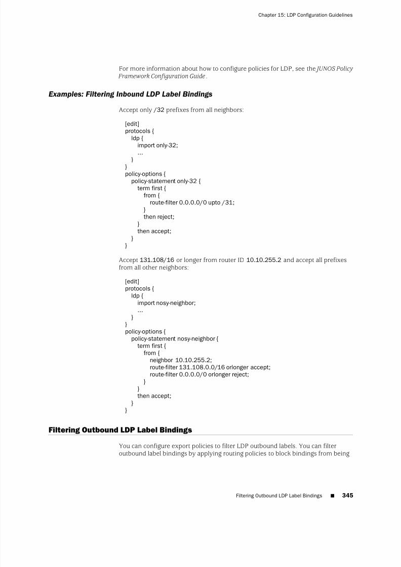
8/7/2019 Config Guide Mpls Applications
http://slidepdf.com/reader/full/config-guide-mpls-applications 383/547
For more information about how to configure policies for LDP, see the JUNOS Policy Framework Configuration Guide.
Examples: Filtering Inbound LDP Label Bindings
Accept only /32 prefixes from all neighbors:
[edit]protocols {
ldp {import only-32;...
}}policy-options {
policy-statement only-32 {term first {
from {route-filter 0.0.0.0/0 upto /31;}then reject;
}then accept;
}}
Accept 131.108/16 or longer from router ID 10.10.255.2 and accept all prefixesfrom all other neighbors:
[edit]protocols {
ldp {import nosy-neighbor;...
}}policy-options {
policy-statement nosy-neighbor {term first {
from {neighbor 10.10.255.2;route-filter 131.108.0.0/16 orlonger accept;route-filter 0.0.0.0/0 orlonger reject;
}}
then accept;}}
Filtering Outbound LDP Label Bindings
You can configure export policies to filter LDP outbound labels. You can filteroutbound label bindings by applying routing policies to block bindings from being
Filtering Outbound LDP Label Bindings ■ 345
Chapter 15: LDP Configuration Guidelines

8/7/2019 Config Guide Mpls Applications
http://slidepdf.com/reader/full/config-guide-mpls-applications 384/547
advertised to neighboring routers. To configure outbound label filtering, include theexport statement:
export [policy-name];
For a list of hierarchy levels at which you can include this statement, see the statementsummary section for this statement.
The named export policy (configured at the [edit policy-options] hierarchy level) isapplied to all label bindings transmitted to all LDP neighbors. The only from operatorthat applies to LDP outbound label filtering is route-filter, which matches bindingswith the specified prefix. The only to operators that apply to outbound label filteringare the operators in Table 8 on page 346.
Table 8: to Operators for LDP Outbound-Label Filtering
Descriptionto Operator
Matches on bindings sent to a neighbor that is adjacent over the specifiedinterface
interface
Matches on bindings sent to the specified LDP router IDneighbor
Matches on bindings sent to a neighbor advertising the specified interfaceaddress
next-hop
If a binding is filtered, the binding is not advertised to the neighboring router, but itcan be installed as part of an LSP on the local router. You can apply policies in LDPto block the establishment of LSPs, but not to control their routing. The path an LSPfollows is determined by unicast routing, not by LDP.
LDP sessions are not bound to interfaces or interface addresses. LDP advertises onlyper-router (not per-interface) labels. If multiple parallel links exist between two routers,only one LDP session is established, and it is not bound to a single interface.
Do not use the next-hop and interface operators when a router has multiple adjacenciesto the same neighbor.
Filtered labels are marked in the database:
user@host> show ldp database
Input label database, 10.10.255.1:0-10.10.255.3:0
Label Prefix
100007 10.10.255.2/323 10.10.255.3/32
Output label database, 10.10.255.1:0-10.10.255.3:0
Label Prefix
3 10.10.255.1/32
100001 10.10.255.6/32 (Filtered)
For more information about how to configure policies for LDP, see the JUNOS Policy Framework Configuration Guide.
346 ■ Filtering Outbound LDP Label Bindings
JUNOS 9.6 MPLS Applications Configuration Guide
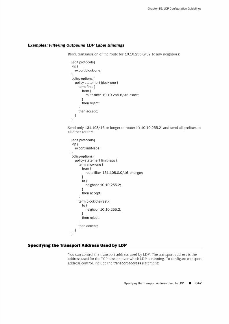
8/7/2019 Config Guide Mpls Applications
http://slidepdf.com/reader/full/config-guide-mpls-applications 385/547

8/7/2019 Config Guide Mpls Applications
http://slidepdf.com/reader/full/config-guide-mpls-applications 386/547
transport-address (router-id | interface);
For a list of hierarchy levels at which you can include this statement, see the statementsummary section for this statement.
If you specify the router-id option, the address of the router identifier is used as thetransport address (unless otherwise configured, the router identifier is typically thesame as the loopback address). If you specify the interface option, the interfaceaddress is used as the transport address for any LDP sessions to neighbors that canbe reached over that interface. Note that the router identifier is used as the transportaddress by default.
You cannot specify the interface option when there are multiple parallel links to thesame LDP neighbor, because the LDP specification requires that the same transportaddress be advertised on all interfaces to the same neighbor. If LDP detects multipleparallel links to the same neighbor, it disables interfaces to that neighbor one by oneuntil the condition is cleared, either by disconnecting the neighbor on an interface
or by specifying the router-id option.
Configuring the Prefixes Advertised into LDP from the Routing Table
You can control the set of prefixes that are advertised into LDP and cause the routerto be the egress router for those prefixes. By default, only the loopback address isadvertised into LDP. To configure the set of prefixes from the routing table to beadvertised into LDP, include the egress-policy statement:
egress-policy policy-name;
For a list of hierarchy levels at which you can include this statement, see the statementsummary section for this statement.
NOTE: If you configure an egress policy for LDP that does not include the loopbackaddress, it is no longer advertised in LDP. To continue to advertise the loopbackaddress, you need to explicitly configure it as a part of the LDP egress policy.
The named policy (configured at the [edit policy-options] or [edit logical-systemslogical-system-name policy-options] hierarchy level) is applied to all routes in the routingtable. Those routes that match the policy are advertised into LDP. You can controlthe set of neighbors to which those prefixes are advertised by using the exportstatement. Only from operators are considered; you can use any valid from operator.For more information, see the JUNOS Routing Protocols Configuration Guide .
Example: Configuring the Prefixes Advertised into LDP
Advertise all connected routes into LDP:
[edit protocols]ldp {
egress-policy connected-only;}policy-options {
348 ■ Configuring the Prefixes Advertised into LDP from the Routing Table
JUNOS 9.6 MPLS Applications Configuration Guide

8/7/2019 Config Guide Mpls Applications
http://slidepdf.com/reader/full/config-guide-mpls-applications 387/547
policy-statement connected-only {from {
protocol direct;}
then accept;}}
Configuring FEC Deaggregation
When an LDP egress router advertises multiple prefixes, the prefixes are bound toa single label and aggregated into a single forwarding equivalence class (FEC). Bydefault, LDP maintains this aggregation as the advertisement traverses the network.
By default, because an LSP cannot be split across multiple next hops and all theprefixes are bound into a single LSP, you cannot load-balance across equal-cost paths.
To change the default to load-balance across equal-cost paths, you need to deaggregatethe FECs. Deaggregating the FECs causes each prefix to be bound to a separate labeland become a separate LSP.
To configure deaggregated FECs, include the deaggregate statement:
deaggregate;
For a list of hierarchy levels at which you can include this statement, see the statementsummary section for this statement.
For all LDP sessions, you can configure deaggregated FECs only globally.
Deaggregating a FEC allows the resulting multiple LSPs to be distributed acrossmultiple equal-cost paths and distributes LSPs across the multiple next hops on theegress segments but installs only one next hop per LSP.
To aggregate FECs, include the no-deaggregate statement:
no-deaggregate;
For a list of hierarchy levels at which you can include this statement, see the statementsummary section for this statement.
For all LDP sessions, you can configure aggregated FECs only globally.
Configuring Policers for LDP FECs
You can configure the JUNOS Software to track and police traffic for LDP FECs. LDPFEC policers can be used to do any of the following:
■ Track or police the ingress traffic for an LDP FEC.
■ Track or police the transit traffic for an LDP FEC.
■ Track or police LDP FEC traffic originating from a specific forwarding class.
Configuring FEC Deaggregation ■ 349
Chapter 15: LDP Configuration Guidelines

8/7/2019 Config Guide Mpls Applications
http://slidepdf.com/reader/full/config-guide-mpls-applications 388/547
■ Track or police LDP FEC traffic originating from a specific virtual routing andforwarding (VRF) site.
■ Discard false traffic bound for a specific LDP FEC.
To police traffic for an LDP FEC, you must first configure a filter. Specifically, youneed to configure either the interface statement or the interface-set statement at the[edit firewall family protocol-family filter filter-name term term-name from] hierarchy level.The interface statement allows you to match the filter to a single interface. Theinterface-set statement allows you to match the filter to multiple interfaces.
For more information on how to configure the interface statement, the interface-setstatement, and policers for LDP FECs, see the JUNOS Policy Framework ConfigurationGuide.
Once you have configured the filters, you need to include them in the policingstatement configuration for LDP. To configure policers for LDP FECs, include the
policing statement:policing {
fec fec-address {ingress-traffic filter-name;transit-traffic filter-name;
}}
For a list of hierarchy levels at which you can include this statement, see the statementsummary section for this statement.
The policing statement includes the following options:
■
fec—
Specify the FEC address for the LDP FEC you want to police.■ ingress-filter—Specify the name of the ingress traffic filter.
■ transit-traffic—Specify the name of the transit traffic filter.
Configuring LDP IPv4 FEC Filtering
By default, when a targeted LDP session is established, the JUNOS Software alwaysexchanges both the IPv4 forwarding equivalence classes (FECs) and the Layer 2circuit FECs over the targeted LDP session. For an LDP session to an indirectlyconnected neighbor, you might only want to export Layer 2 circuit FECs to theneighbor if the session was specifically configured to support Layer 2 circuits or VPLS.
In a mixed vendor network where all non-BGP prefixes are advertised into LDP, theLDP database can become large. For this type of environment, it can be useful toprevent the advertisement of IPv4 FECs over LDP sessions formed due to Layer 2circuit or LDP VPLS configuration. Similarly, it can be useful to filter any IPv4 FECsreceived in this sort of environment.
If all the LDP neighbors associated with an LDP session are Layer 2 only, you canconfigure the JUNOS Software to only advertise Layer 2 circuit FECs by configuringthe l2-smart-policy statement. This feature also automatically filters out the IPv4 FECs
350 ■ Configuring LDP IPv4 FEC Filtering
JUNOS 9.6 MPLS Applications Configuration Guide

8/7/2019 Config Guide Mpls Applications
http://slidepdf.com/reader/full/config-guide-mpls-applications 389/547
received on this session. If you have configured an explicit export or import policy,this feature is disabled.
If one of the LDP session's neighbors is formed due to a discovered adjacency or if
the adjacency is formed due to an LDP tunneling configuration on one or more RSVPLSPs, the IPv4 FECs are advertised and received using the default behavior.
To prevent LDP from exporting IPv4 FECs over LDP sessions with Layer 2 neighborsonly and to filter out IPv4 FECs received over such sessions, include the l2-smart-policystatement:
l2-smart-policy;
For a list of hierarchy levels at which you can configure this statement, see thestatement summary for this statement.
Configuring BFD for LDP LSPs
You can configure Bidirectional Forwarding Detection (BFD) for LDP LSPs. BFD canbe turned on for all or a subset of LDP IPv4 FECs.
An error is logged whenever a BFD session for a path fails. The following shows howBFD for LDP LSP log messages might appear:
RPD_LDP_BFD_UP: LDP BFD session for FEC 10.255.16.14/32 is up
RPD_LDP_BFD_DOWN: LDP BFD session for FEC 10.255.16.14/32 is down
You can also configure BFD for RSVP LSPs, as described in “Configuring BFD forRSVP-Signaled LSPs” on page 167.
To enable BFD for LDP LSPs, include the oam and bfd-liveness-detection statements.You can enable BFD for all LDP LSPs on the router or just for the LDP LSPs associatedwith a specific FEC.
oam {bfd-liveness-detection {
detection-time threshold milliseconds;ecmp;failure-action {
remove-nexthop;remove-route;
}holddown-interval seconds;ingress-policy ingress-policy-name;
minimum-interval milliseconds;minimum-receive-interval milliseconds;minimum-transmit-interval milliseconds;multiplier detection-time-multiplier ;no-adaptation;transmit-interval {
minimum-interval milliseconds;threshold milliseconds;
}}
Configuring BFD for LDP LSPs ■ 351
Chapter 15: LDP Configuration Guidelines

8/7/2019 Config Guide Mpls Applications
http://slidepdf.com/reader/full/config-guide-mpls-applications 390/547
fec fec-address;lsp-ping-interval seconds;periodic-traceroute {
disable;
exp exp-value;fanout fanout-value;frequency minutes;paths number-of-paths;retries retry-attempts;source address;ttl ttl-value;wait seconds;
}}
For a list of hierarchy levels at which you can include this statement, see the statementsummary section for this statement.
The oam statement includes the following options:■ fec—Specify the FEC address.
■ lsp-ping-interval—Specify the duration of the LSP ping interval in seconds. Toissue a ping on an LDP-signaled LSP, use the ping mpls ldp command. For moreinformation, see the JUNOS System Basics and Services Command Reference.
The bfd-liveness-detection statement includes the following options:
■ ecmp—Causes LDP to establish BFD sessions for all ECMP paths configured forthe specified FEC. If you configure the ecmp option, you must also configure theperiodic-traceroute statement for the specified FEC. If you do not do so, the commitfails. You can configure the periodic-traceroute statement at the global hierarchy
level ([edit protocols ldp oam]) while only configuring the ecmp option for a specificFEC ([edit protocols ldp oam fec address bfd-liveness-detection]).
■ holddown-interval—Specifies the duration the BFD session should remain upbefore adding the route or next hop. Specifying a time of 0 seconds causes theroute or next hop to be added as soon as the BFD session comes back up.
■ minimum-interval—Specifies the minimum transmit and receive interval. If youconfigure the minimum-interval option, you do not need to configure theminimum-receive-interval option or the minimum-transmit-interval option.
■ minimum-receive-interval—Specifies the minimum receive interval. The range isfrom 1 through 255,000 milliseconds.
■ minimum-transmit-interval—Specifies the minimum transmit interval. The range
is from 1 through 255,000 milliseconds.■ multiplier—Specifies the detection time multiplier. The range is from 1 through
255.
352 ■ Configuring BFD for LDP LSPs
JUNOS 9.6 MPLS Applications Configuration Guide

8/7/2019 Config Guide Mpls Applications
http://slidepdf.com/reader/full/config-guide-mpls-applications 391/547
Configuring ECMP-Aware BFD for RSVP LSPs
When you configure BFD for a FEC, a BFD session is established for only one activelocal next-hop for the router. However, you can configure multiple BFD sessions,one for each FEC associated with a specific equal-cost multipath (ECMP) path. Forthis to function properly, you also need to configure LDP LSP periodic traceroute.(See “Configuring LDP LSP Traceroute” on page 354.) RSVP LSP traceroute is used todiscover ECMP paths. A BFD session is initiated for each ECMP path discovered.Whenever a BFD session for one of the ECMP paths fails, an error is logged.
RSVP LSP traceroute is run periodically to check the integrity of the ECMP paths. Thefollowing might occur when a problem is discovered:
■ If the latest RSVP LSP traceroute for a FEC differs from the previous traceroute,the BFD sessions associated with that FEC (the BFD sessions for address rangesthat have changed from previous run) are brought down and new BFD sessions
are initiated for the destination addresses in the altered ranges.■ If the RSVP LSP traceroute returns an error (for example, a timeout), all the BFD
sessions associated with that FEC are torn down.
To configure RSVP to establish BFD sessions for all ECMP paths configured for thespecified FEC, include the ecmp statement.
ecmp;
For a list of hierarchy levels at which you can include this statement, see the statementsummary section for this statement.
Along with the ecmp statement, you must also include the periodic-traceroutestatement, either in the global LDP OAM configuration (at the [edit protocols ldp oam]or [edit logical-systems logical-system-name protocols ldp oam] hierarchy level) or inthe configuration for the specified FEC (at the [edit protocols ldp oam fec address] or[edit logical-systems logical-system-name protocols ldp oam fec address] hierarchy level).Otherwise, the commit operation fails.
Configuring a Failure Action for the BFD Session on an LDP LSP
You can configure route and next-hop properties in the event of a BFD session failureevent on an LDP LSP. The failure event could be an existing BFD session that hasgone down or could be a BFD session that never came up. LDP adds back the routeor next hop when the relevant BFD session comes back up.
You can configure one of the following failure action options for the failure-actionstatement in the event of a BFD session failure on the LDP LSP:
■ remove-nexthop—Removes the route corresponding to the next hop of the LSP'sroute at the ingress node when a BFD session failure event is detected.
■ remove-route—Removes the route corresponding to the LSP from the appropriaterouting tables when a BFD session failure event is detected. If the LSP is
Configuring ECMP-Aware BFD for RSVP LSPs ■ 353
Chapter 15: LDP Configuration Guidelines

8/7/2019 Config Guide Mpls Applications
http://slidepdf.com/reader/full/config-guide-mpls-applications 392/547
configured with ECMP and a BFD session corresponding to any path goes down,the route is removed.
To configure a failure action in the event of a BFD session failure on an LDP LSP,include either the remove-nexthop option or the remove-route option for the failure-actionstatement:
failure-action {remove-nexthop;remove-route;
}
For a list of hierarchy levels at which you can include this statement, see the statementsummary section for this statement.
Configuring the Holddown Interval for the BFD Session
You can specify the duration the BFD session should be up before adding a route ornext hop by configuring the holddown-interval statement at either the [edit protocolsldp oam bfd-livenesss-detection] hierarchy level or at the [edit protocols ldp oam fecaddress bfd-livenesss-detection] hierarchy level. Specifying a time of 0 seconds causesthe route or next hop to be added as soon as the BFD session comes back up.
holddown-interval seconds;
For a list of hierarchy levels at which you can include this statement, see the statementsummary section for this statement.
Configuring OAM Ingress Policies for LDP
Using the ingress-policy statement, you can configure an Operation, Administration,and Management (OAM) policy to choose which forwarding equivalence classes(FECs) need to have OAM enabled. If the FEC passes through the policy or if the FECis explicitly configured, OAM is enabled for a FEC. For FECs chosen using a policy,the BFD parameters configured under [edit protocols ldp oam bfd-liveness-detection]are applied.
You configure the OAM ingress policy at the [edit policy-options] hierarchy level. Toconfigure an OAM ingress policy, include the ingress-policy statement:
ingress-policy ingress-policy-name;
You can configure this statement at the following hierarchy levels:
■
[edit protocols ldp oam]■ [edit logical-systems logical-system-name protocols ldp oam]
Configuring LDP LSP Traceroute
You can trace the route followed by an LDP-signaled LSP. LDP LSP traceroute is basedon RFC 4379, Detecting Multi-Protocol Label Switched (MPLS) Data Plane Failures. This
354 ■ Configuring the Holddown Interval for the BFD Session
JUNOS 9.6 MPLS Applications Configuration Guide

8/7/2019 Config Guide Mpls Applications
http://slidepdf.com/reader/full/config-guide-mpls-applications 393/547
feature allows you to periodically trace all paths in a FEC. The FEC topologyinformation is stored in a database accessible from the CLI.
A topology change does not automatically trigger a trace of an LDP LSP. However,
you can manually initiate a traceroute. If the traceroute request is for an FEC that iscurrently in the database, the contents of the database are updated with the results.
The periodic traceroute feature applies to all FECs specified by the oam statementconfigured at the [edit protocols ldp] hierarchy level. To configure periodic LDP LSPtraceroute, include the periodic-traceroute statement:
periodic-traceroute {disable;exp exp-value;fanout fanout-value;frequency minutes;paths number-of-paths;retries retry-attempts;
source address;ttl ttl-value;wait seconds;
}
You can configure this statement at the following hierarchy levels:
■ [edit protocols ldp oam]
■ [edit protocols ldp oam fec address]
The periodic-traceroute statement includes the following options:
■ exp—Specify the class of service to use when sending probes.
■ fanout—Specify the maximum number of next hops to search per node.
■ frequency—Specify the interval between traceroute attempts.
■ paths—Specify the maximum number of paths to search.
■ retries—Specify the number of attempts to send a probe to a specific node beforegiving up.
■ source—Specify the IPv4 source address to use when sending probes.
■ ttl—Specify the maximum time-to-live value. Nodes that are beyond this valueare not traced.
■ wait—Specify the wait interval before resending a probe packet.
Collecting LDP Statistics
LDP traffic statistics show the volume of traffic that has passed through a particularFEC on a router.
When you configure the traffic-statistics statement at the [edit protocols ldp] hierarchylevel, the LDP traffic statistics are gathered periodically and written to a file. You canconfigure how often statistics are collected (in seconds) by using the interval option.
Collecting LDP Statistics ■ 355
Chapter 15: LDP Configuration Guidelines

8/7/2019 Config Guide Mpls Applications
http://slidepdf.com/reader/full/config-guide-mpls-applications 394/547
The default collection interval is 5 minutes. You must configure an LDP statistics file;otherwise LDP traffic statistics are not gathered. If the LSP goes down, the LDPstatistics are reset.
To collect LDP traffic statistics, include the traffic-statistics statement:
traffic-statistics {file filename <files number > <size size> <world-readable | no-world-readable>;interval interval;no-penultimate-hop;
}
For a list of hierarchy levels at which you can include this statement, see the statementsummary section for this statement.
This section includes the following topics:
■ LDP Statistics Output on page 356
■ Disabling LDP Statistics on the Penultimate-Hop Router on page 357■ LDP Statistics Limitations on page 357
LDP Statistics Output
The following is sample output from an LDP statistics file:
FEC Type Packets Bytes Shared
10.255.350.448/32 Transit 0 0 No
Ingress 0 0 No
10.255.350.450/32 Transit 0 0 Yes
Ingress 0 0 No
10.255.350.451/32 Transit 0 0 No
Ingress 0 0 No
220.220.220.1/32 Transit 0 0 Yes
Ingress 0 0 No
220.220.220.2/32 Transit 0 0 Yes
Ingress 0 0 No
220.220.220.3/32 Transit 0 0 Yes
Ingress 0 0 No
May 28 15:02:05, read 12 statistics in 00:00:00 seconds
The following describes each column of data collected in the LDP statistics file:
■ Bytes—Number of bytes of data passed by the FEC since its LSP came up.
■ FEC—FEC for which LDP traffic statistics are collected.
■
Packets—
Number of packets passed by the FEC since its LSP came up.■ read—This number (which appears next to the date and time) might differ from
the actual number of the statistics displayed. Some of the statistics aresummarized before being displayed.
■ Shared—A Yes value indicates that several prefixes are bound to the same label(for example, when several prefixes are advertised with an egress policy). The
356 ■ Collecting LDP Statistics
JUNOS 9.6 MPLS Applications Configuration Guide
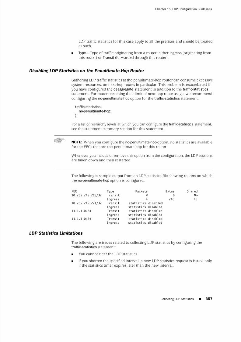
8/7/2019 Config Guide Mpls Applications
http://slidepdf.com/reader/full/config-guide-mpls-applications 395/547
LDP traffic statistics for this case apply to all the prefixes and should be treatedas such.
■ Type—Type of traffic originating from a router, either Ingress (originating fromthis router) or Transit (forwarded through this router).
Disabling LDP Statistics on the Penultimate-Hop Router
Gathering LDP traffic statistics at the penultimate-hop router can consume excessivesystem resources, on next-hop routes in particular. This problem is exacerbated if you have configured the deaggregate statement in addition to the traffic-statisticsstatement. For routers reaching their limit of next-hop route usage, we recommendconfiguring the no-penultimate-hop option for the traffic-statistics statement:
traffic-statistics {no-penultimate-hop;
}
For a list of hierarchy levels at which you can configure the traffic-statistics statement,see the statement summary section for this statement.
NOTE: When you configure the no-penultimate-hop option, no statistics are availablefor the FECs that are the penultimate hop for this router.
Whenever you include or remove this option from the configuration, the LDP sessionsare taken down and then restarted.
The following is sample output from an LDP statistics file showing routers on which
the no-penultimate-hop option is configured:
FEC Type Packets Bytes Shared
10.255.245.218/32 Transit 0 0 No
Ingress 4 246 No
10.255.245.221/32 Transit statistics disabled
Ingress statistics disabled
13.1.1.0/24 Transit statistics disabled
Ingress statistics disabled
13.1.3.0/24 Transit statistics disabled
Ingress statistics disabled
LDP Statistics Limitations
The following are issues related to collecting LDP statistics by configuring thetraffic-statistics statement:
■ You cannot clear the LDP statistics.
■ If you shorten the specified interval, a new LDP statistics request is issued onlyif the statistics timer expires later than the new interval.
Collecting LDP Statistics ■ 357
Chapter 15: LDP Configuration Guidelines
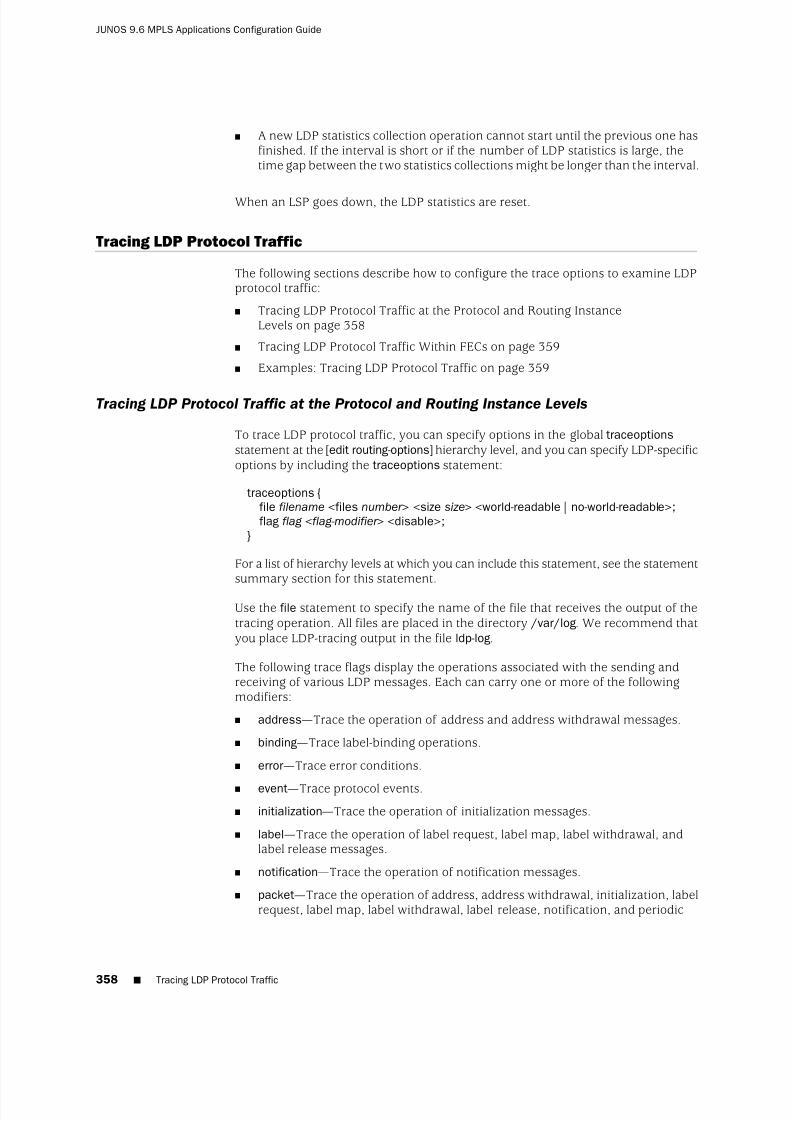
8/7/2019 Config Guide Mpls Applications
http://slidepdf.com/reader/full/config-guide-mpls-applications 396/547
■ A new LDP statistics collection operation cannot start until the previous one hasfinished. If the interval is short or if the number of LDP statistics is large, thetime gap between the two statistics collections might be longer than the interval.
When an LSP goes down, the LDP statistics are reset.
Tracing LDP Protocol Traffic
The following sections describe how to configure the trace options to examine LDPprotocol traffic:
■ Tracing LDP Protocol Traffic at the Protocol and Routing InstanceLevels on page 358
■ Tracing LDP Protocol Traffic Within FECs on page 359
■ Examples: Tracing LDP Protocol Traffic on page 359
Tracing LDP Protocol Traffic at the Protocol and Routing Instance Levels
To trace LDP protocol traffic, you can specify options in the global traceoptionsstatement at the [edit routing-options] hierarchy level, and you can specify LDP-specificoptions by including the traceoptions statement:
traceoptions {file filename <files number > <size size> <world-readable | no-world-readable>;flag flag <flag-modifier > <disable>;
}
For a list of hierarchy levels at which you can include this statement, see the statementsummary section for this statement.
Use the file statement to specify the name of the file that receives the output of thetracing operation. All files are placed in the directory /var/log. We recommend thatyou place LDP-tracing output in the file ldp-log.
The following trace flags display the operations associated with the sending andreceiving of various LDP messages. Each can carry one or more of the followingmodifiers:
■ address—Trace the operation of address and address withdrawal messages.
■ binding—Trace label-binding operations.
■ error—Trace error conditions.
■ event—Trace protocol events.
■ initialization—Trace the operation of initialization messages.
■ label—Trace the operation of label request, label map, label withdrawal, andlabel release messages.
■ notification—Trace the operation of notification messages.
■ packet—Trace the operation of address, address withdrawal, initialization, labelrequest, label map, label withdrawal, label release, notification, and periodic
358 ■ Tracing LDP Protocol Traffic
JUNOS 9.6 MPLS Applications Configuration Guide

8/7/2019 Config Guide Mpls Applications
http://slidepdf.com/reader/full/config-guide-mpls-applications 397/547
messages. This modifier is equivalent to setting the address, initialization, label,notification, and periodic modifiers.
■ path—Trace label-switched path operations.
■ periodic—Trace the operation of hello and keepalive messages.■ route—Trace the operation of route messages.
■ state—Trace protocol state transitions.
Tracing LDP Protocol Traffic Within FECs
You can trace LDP protocol traffic within a specific FEC. You can filter LDP tracestatements based on a FEC. The following trace flags are available for this purpose:route, path, and binding.
The following example illustrates how you might configure the LDP traceoptions
statement to filter LDP trace statements based on a FEC:
[edit protocols ldp traceoptions]flag route filter match-on fec policy "filter-policy-for-ldp-fec";
This feature has the following limitations:
■ The filtering capability is only available for FECs composed of IP version 4 (IPv4)prefixes.
■ Layer 2 circuit FECs cannot be filtered.
■ When you configure both route tracing and filtering, MPLS routes are notdisplayed (they are blocked by the filter).
■ Filtering is determined by the policy and the configured value for the match-onoption. When configuring the policy, be sure that the default behavior is alwaysreject.
■ The only match-on option is fec. Consequently, the only type of policy you shouldinclude is a route-filter policy.
Examples: Tracing LDP Protocol Traffic
Trace LDP path messages in detail:
[edit]protocols {
ldp {traceoptions {
file ldp size 10m files 5;flag path;
}}
}
Trace all LDP outgoing messages:
Tracing LDP Protocol Traffic ■ 359
Chapter 15: LDP Configuration Guidelines

8/7/2019 Config Guide Mpls Applications
http://slidepdf.com/reader/full/config-guide-mpls-applications 398/547
[edit]protocols {
ldp {traceoptions {
file ldp size 10m files 5;flag packets;}
}}
Trace all LDP error conditions:
[edit]protocols {
ldp {traceoptions {
file ldp size 10m files 5;flag error;
}}}
Trace all LDP incoming messages and all label-binding operations:
[edit]protocols {
ldp {traceoptions {
file ldp size 10m files 5 world-readable;flag packets receive;flag binding;
}
interface all {}
}}
Configuring Miscellaneous LDP Properties
The following sections describe how to configure a number of miscellaneous LDPproperties:
■ Configuring LDP to Use the IGP Route Metric on page 361
■ Preventing Addition of Ingress Routes to the inet.0 Routing Table on page 361
■
Multiple-Instance LDP and Carrier-of-Carriers VPNs on page 361■ Configuring MPLS and LDP to Pop the Label on the Ultimate-Hop
Router on page 362
■ Enabling LDP over RSVP-Established LSPs on page 362
■ Enabling LDP over RSVP-Established LSPs in Heterogeneous Networks on page 363
■ Configuring the TCP MD5 Signature for LDP Sessions on page 363
■ Disabling SNMP Traps for LDP on page 364
360 ■ Configuring Miscellaneous LDP Properties
JUNOS 9.6 MPLS Applications Configuration Guide

8/7/2019 Config Guide Mpls Applications
http://slidepdf.com/reader/full/config-guide-mpls-applications 399/547
■ Configuring LDP Synchronization with the IGP on LDP Links on page 364
■ Configuring LDP Synchronization with the IGP on the Router on page 365
■ Configuring the Label Withdrawal Timer on page 365
■ Ignoring the LDP Subnet Check on page 366
Configuring LDP to Use the IGP Route Metric
Use the track-igp-metric statement if you want the interior gateway protocol (IGP)route metric to be used for the LDP routes instead of the default LDP route metric(the default LDP route metric is 1).
To use the IGP route metric, include the track-igp-metric statement:
track-igp-metric;
For a list of hierarchy levels at which you can include this statement, see the statement
summary section for this statement.
Preventing Addition of Ingress Routes to the inet.0 Routing Table
By configuring the no-forwarding statement, you can prevent ingress routes frombeing added to the inet.0 routing table instead of the inet.3 routing table even if youenabled the traffic-engineering bgp-igp statement at the [edit protocols mpls] or the[edit logical-systems logical-system-name protocols mpls] hierarchy level. By default,the no-forwarding statement is disabled.
To omit ingress routes from the inet.0 routing table, include the no-forwardingstatement:
no-forwarding;
For a list of hierarchy levels at which you can include this statement, see the statementsummary section for this statement.
Multiple-Instance LDP and Carrier-of-Carriers VPNs
By configuring multiple LDP routing instances, you can use LDP to advertise labelsin a carrier-of-carriers VPN from a service provider provider edge (PE) router to acustomer carrier customer edge (CE) router. This is especially useful when the carriercustomer is a basic Internet service provider (ISP) and wants to restrict full Internetroutes to its PE routers. By using LDP instead of BGP, the carrier customer shields
its other internal routers from the Internet. Multiple-instance LDP is also useful whena carrier customer wants to provide Layer 2 or Layer 3 VPN services to its customers.
For an example of how to configure multiple LDP routing instances forcarrier-of-carriers VPNs, see the JUNOS Feature Guide.
Configuring Miscellaneous LDP Properties ■ 361
Chapter 15: LDP Configuration Guidelines

8/7/2019 Config Guide Mpls Applications
http://slidepdf.com/reader/full/config-guide-mpls-applications 400/547
Configuring MPLS and LDP to Pop the Label on the Ultimate-Hop Router
The default advertised label is label 3 (Implicit Null label). If label 3 is advertised, thepenultimate-hop router removes the label and sends the packet to the egress router.If ultimate-hop popping is enabled, label 0 (IPv4 Explicit Null label) is advertised.Ultimate-hop popping ensures that any packets traversing an MPLS network includea label.
To configure ultimate-hop popping, include the explicit-null statement:
explicit-null;
For a list of hierarchy levels at which you can include this statement, see the statementsummary section for this statement.
NOTE: Juniper Networks routers queue packets based on the incoming label. Routersfrom other vendors might queue packets differently. Keep this in mind when workingwith networks containing routers from multiple vendors.
For more information about labels, see “Label Description” on page 25 and “LabelAllocation” on page 26.
Enabling LDP over RSVP-Established LSPs
You can run LDP over LSPs established by RSVP, effectively tunneling theLDP-established LSP through the one established by RSVP. To do so, enable LDP onthe lo0.0 interface (see “Enabling and Disabling LDP” on page 338). You must also
configure the LSPs over which you want LDP to operate by including the ldp-tunnelingstatement at the [edit protocols mpls label-switched-path lsp-name] hierarchy level:
[edit]protocols {
mpls {label-switched-path lsp-name {
from source;to destination;ldp-tunneling;
}}
}
For a list of hierarchy levels at which you can include this statement, see the statementsummary section for this statement.
For more information about tunneling LDP LSPs, see “Tunneling LDP LSPs in RSVPLSPs” on page 331.
362 ■ Configuring Miscellaneous LDP Properties
JUNOS 9.6 MPLS Applications Configuration Guide

8/7/2019 Config Guide Mpls Applications
http://slidepdf.com/reader/full/config-guide-mpls-applications 401/547
Enabling LDP over RSVP-Established LSPs in Heterogeneous Networks
Some other vendors use an OSPF metric of 1 for the loopback address. JuniperNetworks routers use an OSPF metric of 0 for the loopback address. This mightrequire that you manually configure the RSVP metric when deploying LDP tunnelingover RSVP LSPs in heterogeneous networks.
When a Juniper Networks router is linked to another vendor’s router through anRSVP tunnel, and LDP tunneling is also enabled, by default the Juniper Networksrouter might not use the RSVP tunnel to route traffic to the LDP destinationsdownstream of the other vendor’s egress router if the RSVP path has a metric of 1larger than the physical OSPF path.
To ensure that LDP tunneling functions properly in heterogeneous networks, youcan configure OSPF to ignore the RSVP LSP metric by including the ignore-lsp-metricsstatement:
ignore-lsp-metrics;
You can configure this statement at the following hierarchy levels:
■ [edit protocols ospf traffic-engineering shortcuts]
■ [edit logical-systems logical-system-name protocols ospf traffic-engineering shortcuts]
To enable LDP over RSVP LSPs, you also still need to complete the procedure in“Enabling LDP over RSVP-Established LSPs” on page 362.
Configuring the TCP MD5 Signature for LDP Sessions
You can configure an MD5 signature for an LDP TCP connection to protect againstthe introduction of spoofed TCP segments into LDP session connection streams.
A router using the MD5 signature option is configured with a password for each peerfor which authentication is required. The password is stored encrypted.
LDP hello adjacencies can still be created even when peering interfaces are configuredwith different security signatures. However, the TCP session cannot be authenticatedand is never established.
NOTE: If you apply an MD5 signature to an LDP interface with an established session,it drops the TCP connection and all the associated label bindings to the FEC entries
for that session. The session regenerates the database information for that sessiononce both interfaces agree on a common security method and password.
To configure an MD5 signature for an LDP TCP connection, include the session andauthentication-key statement:
session address {authentication-key md5-authentication-key ;
Configuring Miscellaneous LDP Properties ■ 363
Chapter 15: LDP Configuration Guidelines

8/7/2019 Config Guide Mpls Applications
http://slidepdf.com/reader/full/config-guide-mpls-applications 402/547
}
For a list of hierarchy levels at which you can include these statements, see thestatement summary section for the session statement.
Use the session statement to configure the address for the remote end of the LDPsession.
The md5-authentication-key (password) can be up to 69 characters long. Characterscan include any ASCII strings. If you include spaces, enclose all characters in quotationmarks.
Disabling SNMP Traps for LDP
Whenever an LDP LSP makes a transition from up to down, or down to up, the routersends an SNMP trap. However, it is possible to disable the LDP SNMP traps on arouter, logical system, or routing instance.
For information about the LDP SNMP traps and the proprietary LDP MIB, see the JUNOS Network Management Configuration Guide .
To disable SNMP traps for LDP, specify the trap disable option for the log-updownstatement:
log-updown {trap disable;
}
For a list of hierarchy levels at which you can include this statement, see the statementsummary section for this statement.
Configuring LDP Synchronization with the IGP on LDP Links
LDP is a protocol for distributing labels in non-traffic-engineered applications. Labelsare distributed along the best path determined by the IGP. If synchronization betweenLDP and the IGP is not maintained, the LSP goes down. When LDP is not fullyoperational on a given link (a session is not established and labels are not exchanged),the IGP advertises the link with the maximum cost metric. The link is not preferredbut remains in the network topology.
LDP synchronization is supported only on active point-to-point interfaces and LANinterfaces configured as point-to-point under the IGP. LDP synchronization is notsupported during graceful restart.
To advertise the maximum cost metric until LDP is operational for synchronization,include the ldp-synchronization statement:
ldp-synchronization {disable;hold-time seconds;
}
364 ■ Configuring Miscellaneous LDP Properties
JUNOS 9.6 MPLS Applications Configuration Guide
8/7/2019 Config Guide Mpls Applications
http://slidepdf.com/reader/full/config-guide-mpls-applications 403/547
To disable synchronization, include the disable statement. To configure the timeperiod to advertise the maximum cost metric for a link that is not fully operational,include the hold-time statement.
For a list of hierarchy levels at which you can configure this statement, see thestatement summary section for this statement.
Configuring LDP Synchronization with the IGP on the Router
To configure LDP synchronization with the IGP on the router, include theigp-synchronization statement and specify a number of seconds as the value of theholddown-interval option:
igp-synchronization holddown-interval seconds;
For a list of hierarchy levels at which you can configure this statement, see thestatement summary section for this statement.
Configuring the Label Withdrawal Timer
The label withdrawal timer delays sending a label withdrawal message for a FEC toa neighbor. When an IGP link to a neighbor fails, the label associated with the FEChas to be withdrawn from all the upstream routers if the neighbor is the next hopfor the FEC. After the IGP converges and a label is received from a new next hop,the label is readvertised to all the upstream routers. This is the typical networkbehavior. By delaying label withdrawal by a small amount of time (for example, untilthe IGP converges and the router receives a new label for the FEC from thedownstream next hop), the label withdrawal and sending a label mapping soon couldbe avoided. The label-withdrawal-delay statement allows you to configure this delaytime. By default, the delay is 60 seconds.
If the router receives the new label before the timer runs out, the label withdrawaltimer is canceled. However, if the timer runs out, the label for the FEC is withdrawnfrom all of the upstream routers.
By default, LDP waits for 60 seconds before withdrawing labels to avoid resignalingLSPs multiple times while the IGP is reconverging. To configure the label withdrawaldelay time in seconds, include the label-withdrawal-delay statement:
label-withdrawal-delay seconds;
For a list of hierarchy levels at which you can configure this statement, see thestatement summary section for this statement.
Configuring Miscellaneous LDP Properties ■ 365
Chapter 15: LDP Configuration Guidelines
8/7/2019 Config Guide Mpls Applications
http://slidepdf.com/reader/full/config-guide-mpls-applications 404/547
Ignoring the LDP Subnet Check
In JUNOS Release 8.4 and later releases, an LDP source address subnet check isperformed during the neighbor establishment procedure. The source address in theLDP link hello packet is matched against the interface address. This causes aninteroperability issue with some other vendors’ equipment.
To disable the subnet check, include the allow-subnet-mismatch statement:
allow-subnet-mismatch;
This statement can be included at the following hierarchy levels:
■ [edit protocols ldp interface interface-name]
■ [edit logical-systems logical-system-name protocols ldp interface interface-name]
366 ■ Configuring Miscellaneous LDP Properties
JUNOS 9.6 MPLS Applications Configuration Guide

8/7/2019 Config Guide Mpls Applications
http://slidepdf.com/reader/full/config-guide-mpls-applications 405/547
Chapter 16
Summary of LDP ConfigurationStatements
This chapter provides a reference for each LDP configuration statement. Thestatements are organized alphabetically.
allow-subnet-mismatch
Syntax allow-subnet-mismatch;
Hierarchy Level [edit logical-systems logical-system-name protocols ldp interface interface-name],[edit protocols ldp interface interface-name]
Release Information Statement introduced in JUNOS Release 9.3.
Description Ignore the LDP subnet check. For JUNOS Release 8.4 and later releases, an LDPsource address subnet check was added for the neighbor establishment procedure.The source address in the LDP link hello packet is matched against the interfaceaddress.
Default The source address in the LDP link hello packet is matched against the interfaceaddress.
Usage Guidelines See “Ignoring the LDP Subnet Check” on page 366.
Required Privilege Level routing—To view this statement in the configuration.routing-control—To add this statement to the configuration.
allow-subnet-mismatch ■ 367

8/7/2019 Config Guide Mpls Applications
http://slidepdf.com/reader/full/config-guide-mpls-applications 406/547
authentication-key
Syntax authentication-key md5-authentication-key ;
Hierarchy Level [edit logical-systems logical-system-name protocols ldp session address],[edit logical-systems logical-system-name routing-instances routing-instance-name protocols
ldp session address],[edit protocols ldp session address],[edit routing-instances routing-instance-name protocols ldp session address]
Release Information Statement introduced before JUNOS Release 7.4.
Description Configure the MD5 authentication signature. The maximum length of theauthentication signature is 69 characters.
Usage Guidelines See “Configuring the TCP MD5 Signature for LDP Sessions” on page 363.
Required Privilege Level routing—To view this statement in the configuration.routing-control—To add this statement to the configuration.
368 ■ authentication-key
JUNOS 9.6 MPLS Applications Configuration Guide

8/7/2019 Config Guide Mpls Applications
http://slidepdf.com/reader/full/config-guide-mpls-applications 407/547
bfd-liveness-detection
Syntax bfd-liveness-detection {detection-time threshold milliseconds;ecmp;failure-action {
remove-nexthop;remove-route;
}holddown-interval seconds;minimum-interval milliseconds;minimum-receive-interval milliseconds;minimum-transmit-interval milliseconds;multiplier detection-time-multiplier ;no-adaptation;
transmit-interval {minimum-interval milliseconds;threshold milliseconds;
}}
Hierarchy Level [edit logical-systems logical-system-name protocols ldp oam],[edit logical-systems logical-system-name protocols ldp oam fec address],[edit protocols ldp oam],[edit protocols ldp oam fec address]
Release Information Statement introduced in JUNOS Release 7.6.Support for the bfd-liveness-detection statement at the [edit protocols ldp oam fec
address] hierarchy level and the ecmp option were added in JUNOS Release 9.0.Support for the failure-action statement with the remove-nexthop and remove-routeoptions and the holddown-interval statement were added in JUNOS Release 9.4.
Description Enable Bidirectional Forwarding Detection (BFD) for all MPLS LSPs or for just a specificLSP.
Options minimum-interval—Minimum transmit and receive interval.Range: 50 through 255,000 millisecondsDefault: 50
minimum-receive-interval—Minimum receive interval.Range: 50 through 255,000 millisecondsDefault: 50
minimum-transmit-interval—Minimum transmit interval.Range: 50 through 255,000 millisecondsDefault: 50
multiplier—Detection time multiplier.Range: 50 through 255Default: 3
bfd-liveness-detection ■ 369
Chapter 16: Summary of LDP Configuration Statements

8/7/2019 Config Guide Mpls Applications
http://slidepdf.com/reader/full/config-guide-mpls-applications 408/547
The other options are explained separately.
Usage Guidelines See “Configuring BFD for LDP LSPs” on page 351.
Required Privilege Level routing—
To view this statement in the configuration.routing-control—To add this statement to the configuration.
deaggregate
Syntax deaggregate | no-deaggregate;
Hierarchy Level [edit logical-systems logical-system-name protocols ldp],[edit logical-systems logical-system-name routing-instances routing-instance-name protocols
ldp],[edit protocols ldp],[edit routing-instances routing-instance-name protocols ldp]
Release Information Statement introduced before JUNOS Release 7.4.
Description Control forwarding equivalence class (FEC) deaggregation on the router.
Default Deaggregation is disabled on the router.
Options deaggregate—Deaggregate FECs.
no-deaggregate—Aggregate FECs.
Usage Guidelines See “Configuring FEC Deaggregation” on page 349.
Required Privilege Level
routing—
To view this statement in the configuration.routing-control—To add this statement to the configuration.
370 ■ deaggregate
JUNOS 9.6 MPLS Applications Configuration Guide

8/7/2019 Config Guide Mpls Applications
http://slidepdf.com/reader/full/config-guide-mpls-applications 409/547
disable
Syntax disable;
Hierarchy Level [edit logical-systems logical-system-name protocols ldp graceful-restart],[edit logical-systems logical-system-name protocols ldp interface interface-name],[edit logical-systems logical-system-name routing-instances routing-instance-name protocols
ldp interface interface-name],[edit logical-systems logical-system-name routing-instances routing-instance-name
routing-options graceful-restart],[edit protocols ldp graceful-restart],[edit protocols ldp interface interface-name],[edit routing-instances routing-instance-name protocols ldp interface interface-name],[edit routing-instances routing-instance-name routing-options graceful-restart]
Release Information Statement introduced before JUNOS Release 7.4.
Description Explicitly disable LDP on an interface, or explicitly disable LDP graceful restart.
Default LDP is enabled on interfaces configured with the LDP interface statement. LDP gracefulrestart is automatically enabled when graceful restart is enabled under the [editrouting-options] hierarchy level.
Usage Guidelines See “Enabling and Disabling LDP” on page 338 and “Configuring LDP Graceful Restart”on page 342.
Required Privilege Level routing—To view this statement in the configuration.routing-control—To add this statement to the configuration.
disable ■ 371
Chapter 16: Summary of LDP Configuration Statements

8/7/2019 Config Guide Mpls Applications
http://slidepdf.com/reader/full/config-guide-mpls-applications 410/547
ecmp
Syntax ecmp;
Hierarchy Level [edit logical-systems logical-system-name protocols ldp oam bfd-liveness-detection],[edit logical-systems logical-system-name protocols ldp oam fec address
bfd-liveness-detection],[edit protocols ldp oam bfd-liveness-detection],[edit protocols ldp oam fec address bfd-liveness-detection]
Release Information Statement introduced in JUNOS Release 8.5.
Description Cause RSVP to establish BFD sessions for all ECMP paths configured for the specifiedFEC. If you configure the ecmp statement, you must also configure theperiodic-traceroute statement for the specified FEC. If you do not do so, the commit
fails. You can configure the periodic-traceroute statement at the global hierarchy level([edit protocols ldp oam]) while only configuring the ecmp statement for a specificFEC ([edit protocols ldp oam fec address bfd-liveness-detection]).
Usage Guidelines See “Configuring ECMP-Aware BFD for RSVP LSPs” on page 353.
Required Privilege Level routing—To view this statement in the configuration.routing-control—To add this statement to the configuration.
egress-policy
Syntax egress-policy [ policy-names ];
Hierarchy Level [edit logical-systems logical-system-name protocols ldp],[edit logical-systems logical-system-name routing-instances routing-instance-name protocols
ldp],[edit protocols ldp],[edit routing-instances routing-instance-name protocols ldp]
Release Information Statement introduced before JUNOS Release 7.4.
Description Control the prefixes advertised into LDP.
Default Only the loopback address is advertised.
Options policy-names—
Name of one or more routing policies.
Usage Guidelines See “Configuring the Prefixes Advertised into LDP from the Routing Table” on page348.
Required Privilege Level routing—To view this statement in the configuration.routing-control—To add this statement to the configuration.
372 ■ ecmp
JUNOS 9.6 MPLS Applications Configuration Guide

8/7/2019 Config Guide Mpls Applications
http://slidepdf.com/reader/full/config-guide-mpls-applications 411/547
explicit-null
Syntax explicit-null;
Hierarchy Level [edit logical-systems logical-system-name protocols ldp],[edit logical-systems logical-system-name routing-instances routing-instance-name protocols
ldp],[edit protocols ldp],[edit routing-instances routing-instance-name protocols ldp]
Release Information Statement introduced before JUNOS Release 7.4.
Description Advertise label 0 to the egress router of a label-switched path (LSP).
Default If you do not include the explicit-null statement in the MPLS configuration, label 3
(implicit null) is advertised.
Usage Guidelines See “Configuring MPLS and LDP to Pop the Label on the Ultimate-Hop Router” onpage 362.
Required Privilege Level routing—To view this statement in the configuration.routing-control—To add this statement to the configuration.
export
Syntax export [ policy-names ];
Hierarchy Level [edit logical-systems logical-system-name protocols ldp],[edit logical-systems logical-system-name routing-instances routing-instance-name protocols
ldp],[edit protocols ldp],[edit routing-instances routing-instance-name protocols ldp]
Release Information Statement introduced before JUNOS Release 7.4.
Description Apply policy filters to outbound LDP label bindings. Filters are applied to all labelbindings from all neighbors.
Options policy-names—Name of one or more routing policies.
Usage Guidelines See“
Filtering Outbound LDP Label Bindings”
on page 345.Required Privilege Level routing—To view this statement in the configuration.
routing-control—To add this statement to the configuration.
explicit-null ■ 373
Chapter 16: Summary of LDP Configuration Statements

8/7/2019 Config Guide Mpls Applications
http://slidepdf.com/reader/full/config-guide-mpls-applications 412/547
failure-action
Syntax failure-action {remove-nexthop;remove-route;
}
Hierarchy Level [edit logical-systems logical-system-name protocols ldp oam bfd-livenesss-detection],[edit logical-systems logical-system-name protocols ldp oam fec address
bfd-livenesss-detection],[edit protocols ldp oam bfd-livenesss-detection],[edit protocols ldp oam fec address bfd-livenesss-detection]
Release Information Statement introduced in JUNOS Release 9.4.
Description Configure route and next-hop properties in the event of a BFD session failure eventon an LDP LSP. The failure event could be an existing BFD session that has gonedown or could be a BFD session that never came up. LDP adds back the route ornext hop when the relevant BFD session comes back up.
Options remove-nexthop—Removes a route corresponding to a next hop of the LSP's route atthe ingress node when a BFD session failure event is detected.
remove-route—Removes the route corresponding to an LSP from the appropriaterouting tables when a BFD session failure event is detected. If the LSP isconfigured with ECMP and a BFD session corresponding to any path goes down,the route is removed.
Usage Guidelines
See“
Configuring a Failure Action for the BFD Session on an LDP LSP”
on page 353.Required Privilege Level routing—To view this statement in the configuration.
routing-control—To add this statement to the configuration.
374 ■ failure-action
JUNOS 9.6 MPLS Applications Configuration Guide
8/7/2019 Config Guide Mpls Applications
http://slidepdf.com/reader/full/config-guide-mpls-applications 413/547
graceful-restart
Syntax graceful-restart {disable;helper-disable;maximum-neighbor-recovery-timevalue;recovery-time value;
}
Hierarchy Level [edit logical-systems logical-system-name protocols ldp],[edit logical-systems logical-system-name routing-instances routing-instance-name protocols
ldp],[edit protocols ldp],[edit routing-instances routing-instance-name protocols ldp]
Release Information Statement introduced before JUNOS Release 7.4.
Description Enable LDP graceful restart on the LDP master protocol instance or for a specificrouting instance.
Usage Guidelines See “Configuring LDP Graceful Restart” on page 342.
Required Privilege Level routing—To view this statement in the configuration.routing-control—To add this statement to the configuration.
graceful-restart ■ 375
Chapter 16: Summary of LDP Configuration Statements

8/7/2019 Config Guide Mpls Applications
http://slidepdf.com/reader/full/config-guide-mpls-applications 414/547
hello-interval
Syntax hello-interval seconds;
Hierarchy Level [edit logical-systems logical-system-name protocols ldp interface interface-name],[edit logical-systems logical-system-name protocols ldp targeted-hello],[edit logical-systems logical-system-name routing-instances routing-instance-name protocols
ldp interface interface-name],[edit logical-systems logical-system-name routing-instances routing-instance-name protocols
ldp targeted-hello],[edit protocols ldp interface interface-name],[edit protocols ldp targeted-hello],[edit routing-instances routing-instance-name protocols ldp interface interface-name][edit routing-instances routing-instance-name protocols ldp targeted-hello]
Release Information Statement introduced before JUNOS Release 7.4. Support for LDP targeted hellosadded in JUNOS Release 9.5.
Description Controls the LDP timer that regulates how often hello messages are sent. You cancontrol the rate both link hello messages and targeted hello messages are sentdepending on the hierarchy level at which you configure the hello-interval statement.
Options seconds—Length of time between transmission of hello packets.Range: 1 through 65,535 secondsDefault: 5 seconds for link hello messages, 15 seconds for targeted hellomessages
Usage Guidelines See “Configuring the LDP Timer for Hello Messages” on page 338.
Required Privilege Level routing—To view this statement in the configuration.routing-control—To add this statement to the configuration.
376 ■ hello-interval
JUNOS 9.6 MPLS Applications Configuration Guide

8/7/2019 Config Guide Mpls Applications
http://slidepdf.com/reader/full/config-guide-mpls-applications 415/547
helper-disable
Syntax helper-disable;
Hierarchy Level [edit logical-systems logical-system-name protocols ldp graceful-restart],[edit logical-systems logical-system-name routing-instances routing-instance-name protocols
ldp graceful-restart],[edit protocols ldp graceful-restart],[edit routing-instances routing-instance-name protocols ldp graceful-restart]
Release Information Statement introduced before JUNOS Release 7.4.
Description Disable helper mode for LDP graceful restart. When helper mode is disabled, a routercannot help a neighboring router that is attempting to restart LDP.
Default Helper mode is enabled by default on all routing protocols (including LDP) that supportgraceful restart.
Usage Guidelines See “Configuring LDP Graceful Restart” on page 342.
Required Privilege Level routing—To view this statement in the configuration.routing-control—To add this statement to the configuration.
holddown-interval
Syntax holddown-interval holddown-interval;
Hierarchy Level [edit logical-systems logical-system-name protocols ldp oam bfd-livenesss-detection],[edit logical-systems logical-system-name protocols ldp oam fec address
bfd-livenesss-detection],[edit protocols ldp oam bfd-livenesss-detection],[edit protocols ldp oam fec address bfd-livenesss-detection]
Release Information Statement introduced in JUNOS Release 9.4.
Description Specifies how long the BFD session should be up before adding the route or nexthop. Specifying a time of 0 seconds causes the route or next hop to be added as soonas the BFD session comes back up.
Options holddown-interval—Number of seconds the BFD session should remain up before
adding the route or next hop.Default: 0 secondsRange: 0 through 65,535 seconds
Usage Guidelines See “Configuring the Holddown Interval for the BFD Session” on page 354.
Required Privilege Level routing—To view this statement in the configuration.routing-control—To add this statement to the configuration.
helper-disable ■ 377
Chapter 16: Summary of LDP Configuration Statements
8/7/2019 Config Guide Mpls Applications
http://slidepdf.com/reader/full/config-guide-mpls-applications 416/547
hold-time
Syntax hold-time seconds;
Hierarchy Level [edit logical-systems logical-system-name protocols ldp interface interface-name],[edit logical-systems logical-system-name protocols ldp targeted-hello],[edit logical-systems logical-system-name routing-instances routing-instance-name protocols
ldp interface interface-name],[edit logical-systems logical-system-name routing-instances routing-instance-name protocols
ldp targeted-hello],[edit protocols ldp interface interface-name],[edit protocols ldp targeted-hello],[edit routing-instances routing-instance-name protocols ldp interface interface-name][edit routing-instances routing-instance-name protocols ldp targeted-hello]
Release Information Statement introduced before JUNOS Release 7.4. Support for LDP targeted hellosadded in JUNOS Release 9.5.
Description Specify how long an LDP node should wait for a hello message before declaring aneighbor to be down. This value is sent as part of a hello message so that each LDPnode tells its neighbors how long to wait. You can specify times for both link hellomessages and targeted hello messages depending on which hierarchy level youconfigure the hold-time statement.
Options seconds—Hold-time value.Range: 1 through 65,535 secondsDefault: 15 seconds for link hello messages, 45 seconds for targeted hellomessages
Usage Guidelines See “Configuring the Delay Before LDP Neighbors Are Considered Down” on page339.
Required Privilege Level routing—To view this statement in the configuration.routing-control—To add this statement to the configuration.
378 ■ hold-time
JUNOS 9.6 MPLS Applications Configuration Guide

8/7/2019 Config Guide Mpls Applications
http://slidepdf.com/reader/full/config-guide-mpls-applications 417/547
ignore-lsp-metrics
Syntax ignore-lsp-metrics;
Hierarchy Level [edit logical-systems logical-system-name protocols ospf traffic-engineering shortcuts],[edit protocols ospf traffic-engineering shortcuts]
Release Information Statement introduced in JUNOS Release 7.5.
Description Cause OSPF to ignore the RSVP LSP metric.
Some other vendors use an OSPF metric of 1 for the loopback address. JuniperNetworks routers use an OSPF metric of 0 for the loopback address. This can causeinteroperability problems when you configure LDP tunneling over RSVP LSPs inheterogeneous networks.
Usage Guidelines See “Enabling LDP over RSVP-Established LSPs in Heterogeneous Networks” on page363.
Required Privilege Level routing—To view this statement in the configuration.routing-control—To add this statement to the configuration.
igp-synchronization
Syntax igp-synchronization holddown-interval seconds;
Hierarchy Level [edit logical-systems logical-system-name protocols ldp],[edit logical-systems logical-system-name routing-instances routing-instance-name protocols
ldp],[edit protocols ldp],[edit routing-instances routing-instance-name protocols ldp]
Release Information Statement introduced in JUNOS Release 9.5.
Description Configures the time the JUNOS Software waits to allow LDP to synchronize with theIGP. For large networks with numerous FECs, it might be necessary to configure alonger value to allow enough time for network convergence.
Options holddown-interval seconds—Specify the time to wait for LDP to synchronize with theIGP in seconds.
Default: 10 secondsRange: 10 through 60 seconds
Usage Guidelines See “Configuring LDP Synchronization with the IGP on the Router” on page 365.
Required Privilege Level routing—To view this statement in the configuration.routing-control—To add this statement to the configuration.
ignore-lsp-metrics ■ 379
Chapter 16: Summary of LDP Configuration Statements
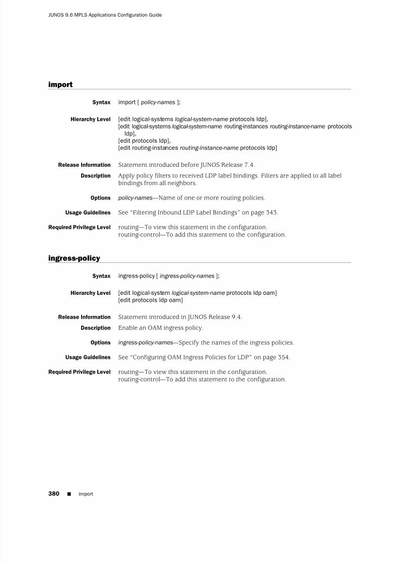
8/7/2019 Config Guide Mpls Applications
http://slidepdf.com/reader/full/config-guide-mpls-applications 418/547
import
Syntax import [ policy-names ];
Hierarchy Level [edit logical-systems logical-system-name protocols ldp],[edit logical-systems logical-system-name routing-instances routing-instance-name protocols
ldp],[edit protocols ldp],[edit routing-instances routing-instance-name protocols ldp]
Release Information Statement introduced before JUNOS Release 7.4.
Description Apply policy filters to received LDP label bindings. Filters are applied to all labelbindings from all neighbors.
Options policy-names—Name of one or more routing policies.
Usage Guidelines See “Filtering Inbound LDP Label Bindings” on page 343.
Required Privilege Level routing—To view this statement in the configuration.routing-control—To add this statement to the configuration.
ingress-policy
Syntax ingress-policy [ ingress-policy-names ];
Hierarchy Level [edit logical-system logical-system-name protocols ldp oam][edit protocols ldp oam]
Release Information Statement introduced in JUNOS Release 9.4.
Description Enable an OAM ingress policy.
Options ingress-policy-names—Specify the names of the ingress policies.
Usage Guidelines See “Configuring OAM Ingress Policies for LDP” on page 354.
Required Privilege Level routing—To view this statement in the configuration.routing-control—To add this statement to the configuration.
380 ■ import
JUNOS 9.6 MPLS Applications Configuration Guide
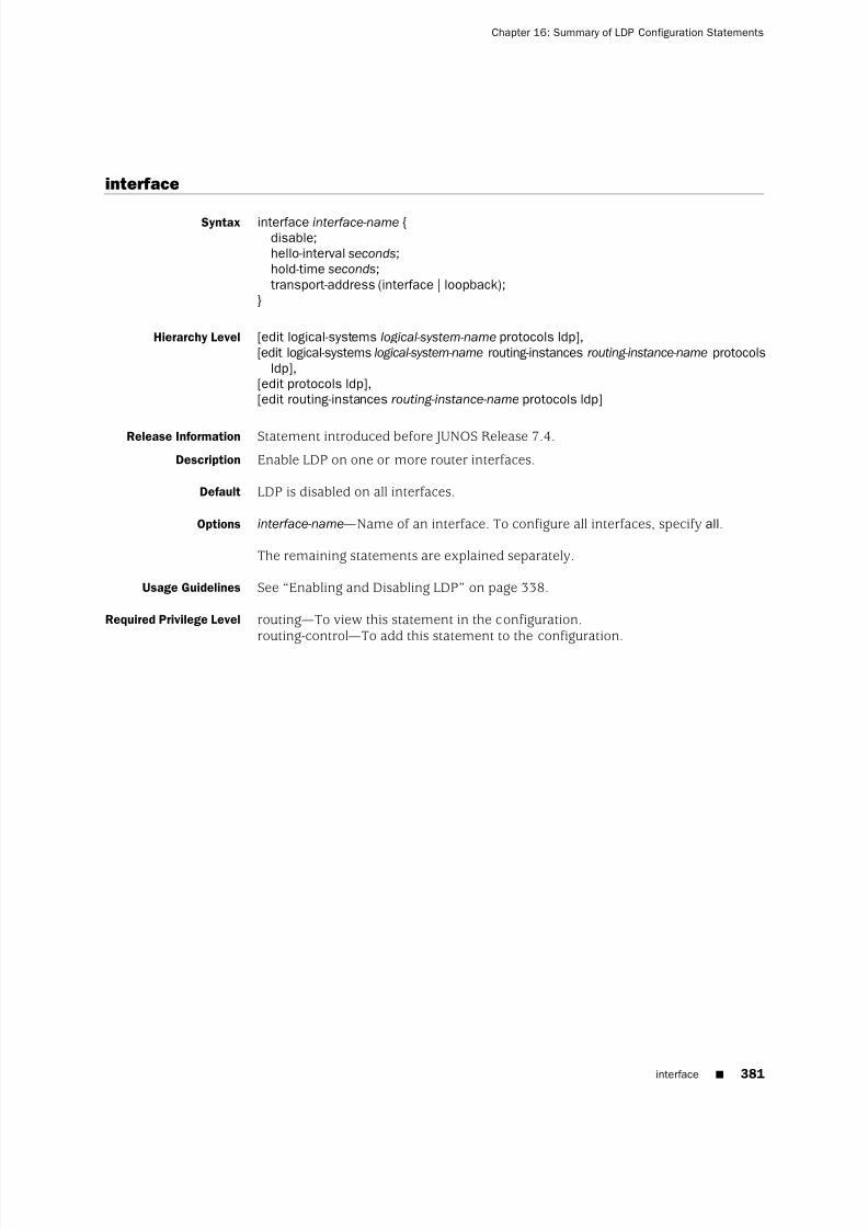
8/7/2019 Config Guide Mpls Applications
http://slidepdf.com/reader/full/config-guide-mpls-applications 419/547
interface
Syntax interface interface-name {disable;hello-interval seconds;hold-time seconds;transport-address (interface | loopback);
}
Hierarchy Level [edit logical-systems logical-system-name protocols ldp],[edit logical-systems logical-system-name routing-instances routing-instance-name protocols
ldp],[edit protocols ldp],[edit routing-instances routing-instance-name protocols ldp]
Release Information Statement introduced before JUNOS Release 7.4.
Description Enable LDP on one or more router interfaces.
Default LDP is disabled on all interfaces.
Options interface-name—Name of an interface. To configure all interfaces, specify all.
The remaining statements are explained separately.
Usage Guidelines See “Enabling and Disabling LDP” on page 338.
Required Privilege Level routing—To view this statement in the configuration.routing-control—To add this statement to the configuration.
interface ■ 381
Chapter 16: Summary of LDP Configuration Statements

8/7/2019 Config Guide Mpls Applications
http://slidepdf.com/reader/full/config-guide-mpls-applications 420/547
keepalive-interval
Syntax keepalive-interval seconds;
Hierarchy Level [edit logical-systems logical-system-name protocols ldp],[edit logical-systems logical-system-name routing-instances routing-instance-name protocols
ldp],[edit protocols ldp],[edit routing-instances routing-instance-name protocols ldp]
Release Information Statement introduced before JUNOS Release 7.4.
Description Set the keepalive interval value.
Options seconds—Keepalive value.
Range: 1 through 65,535Default: 10 seconds
Usage Guidelines See “Configuring the Interval for LDP Keepalive Messages” on page 341.
Required Privilege Level routing—To view this statement in the configuration.routing-control—To add this statement to the configuration.
keepalive-timeout
Syntax keepalive-timeout seconds;
Hierarchy Level [edit logical-systems logical-system-name protocols ldp],[edit logical-systems logical-system-name routing-instances routing-instance-name protocols
ldp],[edit protocols ldp],[edit routing-instances routing-instance-name protocols ldp]
Release Information Statement introduced before JUNOS Release 7.4.
Description Set the keepalive timeout value. The keepalive timeout defines the amount of timethat the neighbor LDP node waits before determining that the session has failed.
Options seconds—Keepalive timeout value.Range: 1 through 65,535Default: 30 seconds
Usage Guidelines See “Configuring the LDP Keepalive Timeout” on page 341.
Required Privilege Level routing—To view this statement in the configuration.routing-control—To add this statement to the configuration.
382 ■ keepalive-interval
JUNOS 9.6 MPLS Applications Configuration Guide
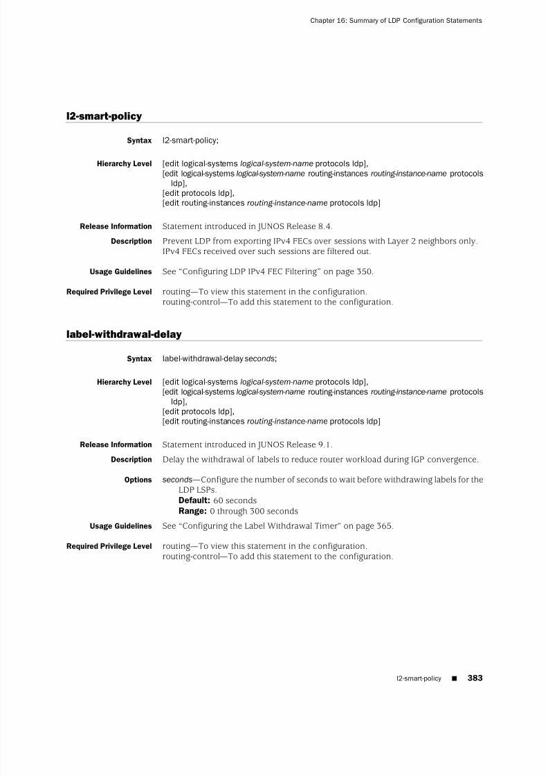
8/7/2019 Config Guide Mpls Applications
http://slidepdf.com/reader/full/config-guide-mpls-applications 421/547
l2-smart-policy
Syntax l2-smart-policy;
Hierarchy Level [edit logical-systems logical-system-name protocols ldp],[edit logical-systems logical-system-name routing-instances routing-instance-name protocols
ldp],[edit protocols ldp],[edit routing-instances routing-instance-name protocols ldp]
Release Information Statement introduced in JUNOS Release 8.4.
Description Prevent LDP from exporting IPv4 FECs over sessions with Layer 2 neighbors only.IPv4 FECs received over such sessions are filtered out.
Usage Guidelines See “Configuring LDP IPv4 FEC Filtering” on page 350.
Required Privilege Level routing—To view this statement in the configuration.routing-control—To add this statement to the configuration.
label-withdrawal-delay
Syntax label-withdrawal-delay seconds;
Hierarchy Level [edit logical-systems logical-system-name protocols ldp],[edit logical-systems logical-system-name routing-instances routing-instance-name protocols
ldp],[edit protocols ldp],[edit routing-instances routing-instance-name protocols ldp]
Release Information Statement introduced in JUNOS Release 9.1.
Description Delay the withdrawal of labels to reduce router workload during IGP convergence.
Options seconds—Configure the number of seconds to wait before withdrawing labels for theLDP LSPs.Default: 60 secondsRange: 0 through 300 seconds
Usage Guidelines See “Configuring the Label Withdrawal Timer” on page 365.
Required Privilege Level routing—To view this statement in the configuration.routing-control—To add this statement to the configuration.
l2-smart-policy ■ 383
Chapter 16: Summary of LDP Configuration Statements
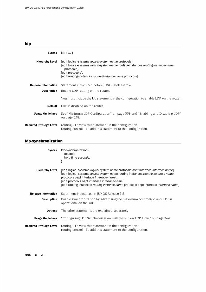
8/7/2019 Config Guide Mpls Applications
http://slidepdf.com/reader/full/config-guide-mpls-applications 422/547
ldp
Syntax ldp { ... }
Hierarchy Level [edit logical-systems logical-system-name protocols],[edit logical-systems logical-system-name routing-instances routing-instance-name
protocols],[edit protocols],[edit routing-instances routing-instance-name protocols]
Release Information Statement introduced before JUNOS Release 7.4.
Description Enable LDP routing on the router.
You must include the ldp statement in the configuration to enable LDP on the router.
Default LDP is disabled on the router.
Usage Guidelines See “Minimum LDP Configuration” on page 338 and “Enabling and Disabling LDP”on page 338.
Required Privilege Level routing—To view this statement in the configuration.routing-control—To add this statement to the configuration.
ldp-synchronization
Syntax ldp-synchronization {
disable;hold-time seconds;
}
Hierarchy Level [edit logical-systems logical-system-name protocols ospf interface interface-name],[edit logical-systems logical-system-name routing-instances routing-instance-name
protocols ospf interface interface-name],[edit protocols ospf interface interface-name],[edit routing-instances routing-instance-name protocols ospf interface interface-name]
Release Information Statement introduced in JUNOS Release 7.5.
Description Enable synchronization by advertising the maximum cost metric until LDP is
operational on the link.Options The other statements are explained separately.
Usage Guidelines “Configuring LDP Synchronization with the IGP on LDP Links” on page 364
Required Privilege Level routing—To view this statement in the configuration.routing-control—To add this statement to the configuration.
384 ■ ldp
JUNOS 9.6 MPLS Applications Configuration Guide

8/7/2019 Config Guide Mpls Applications
http://slidepdf.com/reader/full/config-guide-mpls-applications 423/547
log-updown
Syntax log-updown {trap disable;
}
Hierarchy Level [edit logical-systems logical-system-name protocols ldp],[edit logical-systems logical-system-name routing-instances routing-instance-name protocols
ldp],[edit protocols ldp],[edit routing-instances routing-instance-name protocols ldp]
Release Information Statement introduced before JUNOS Release 7.4.
Description Disable LDP traps on the router, logical system, or routing instance.
Options trap disable—Disable LDP traps.Default: LDP traps are enabled on the router.
Usage Guidelines See “Disabling SNMP Traps for LDP” on page 364.
Required Privilege Level routing—To view this statement in the configuration.routing-control—To add this statement to the configuration.
maximum-neighbor-recovery-time
Syntax maximum-neighbor-recovery-time seconds;
Hierarchy Level [edit logical-systems logical-system-name protocols ldp graceful-restart],[edit logical-systems logical-system-name routing-instances routing-instance-name protocols
ldp graceful-restart],[edit protocols ldp graceful-restart],[edit routing-instances routing-instance-name protocols ldp graceful-restart]
Release Information Statement introduced before JUNOS Release 7.4. Statement changed frommaximum-recovery-time to maximum-neighbor-recovery-time in JUNOS Release 9.1.
Description Specify the maximum amount of time to wait before giving up an attempt to gracefullyrestart.
Options seconds—Configure the maximum recovery time, in seconds.Range: 120 through 1800 secondsDefault: 140 seconds
Usage Guidelines See “Configuring Recovery Time and Maximum Recovery Time” on page 343.
Required Privilege Level routing—To view this statement in the configuration.routing-control—To add this statement to the configuration.
log-updown ■ 385
Chapter 16: Summary of LDP Configuration Statements
8/7/2019 Config Guide Mpls Applications
http://slidepdf.com/reader/full/config-guide-mpls-applications 424/547
no-deaggregate
See deaggregate.
no-forwarding
Syntax no-forwarding;
Hierarchy Level [edit logical-systems logical-system-name protocols ldp],[edit logical-systems logical-system-name routing-instances routing-instance-name protocols
ldp],[edit protocols ldp],[edit routing-instances routing-instance-name protocols ldp]
Release Information Statement introduced before JUNOS Release 7.4.
Description Do not add ingress routes to the inet.0 routing table even if traffic-engineering bgp-igp(configured at the [edit protocols mpls] hierarchy level) is enabled.
Default The no-forwarding statement is disabled. Ingress routes are added to the inet.0 routingtable instead of the inet.3 routing table when traffic-engineering bgp-igp is enabled.
Usage Guidelines See “Preventing Addition of Ingress Routes to the inet.0 Routing Table” on page 361.
Required Privilege Level routing—To view this statement in the configuration.routing-control—To add this statement to the configuration.
386 ■ no-deaggregate
JUNOS 9.6 MPLS Applications Configuration Guide

8/7/2019 Config Guide Mpls Applications
http://slidepdf.com/reader/full/config-guide-mpls-applications 425/547
oam
Syntax oam {bfd-liveness-detection {
detection-time threshold milliseconds;ecmp;failure-action {
remove-nexthop;remove-route;
}holddown-interval milliseconds;ingress-policy ingress-policy-name
minimum-interval milliseconds;minimum-receive-interval milliseconds;minimum-transmit-interval milliseconds;
multiplier detection-time-multiplier ;no-adaptation;transmit-interval {
minimum-interval milliseconds;threshold milliseconds;
}}fec fec-address;ingress-policy ingress-policy-name;lsp-ping-interval seconds;periodic-traceroute {
disable;exp exp-value;fanout fanout-value;
frequency minutes;paths number-of-paths;retries retry-attempts;source address;ttl ttl-value;wait seconds;
}}
Hierarchy Level [edit protocols ldp]
Release Information Statement introduced in JUNOS Release 7.6. The lsp-ping-intervaloption was introducedin JUNOS Release 9.4.
Description Enable OAM for all of the LDP LSPs or for a specific LDP LSP.
Options fec fec-address—Specify the forwarding equivalence class (FEC) address.
lsp-ping-interval seconds—Specify the duration of the LSP ping interval in seconds.To issue a ping on an LDP-signaled LSP, use the ping mpls ldp command.
The remaining statements are explained separately.
oam ■ 387
Chapter 16: Summary of LDP Configuration Statements

8/7/2019 Config Guide Mpls Applications
http://slidepdf.com/reader/full/config-guide-mpls-applications 426/547
Usage Guidelines See “Configuring BFD for LDP LSPs” on page 351.
Required Privilege Level routing—To view this statement in the configuration.routing-control—To add this statement to the configuration.
388 ■ oam
JUNOS 9.6 MPLS Applications Configuration Guide

8/7/2019 Config Guide Mpls Applications
http://slidepdf.com/reader/full/config-guide-mpls-applications 427/547
periodic-traceroute
Syntax periodic-traceroute {disable;exp exp-value;fanout fanout-value;frequency minutes;paths number-of-paths;retries retry-attempts;source address;ttl ttl-value;wait seconds;
}
Hierarchy Level [edit logical-systems logical-system-name protocols ldp oam],
[edit logical-systems logical-system-name protocols ldp oam fec fec-address],[edit protocols ldp oam],[edit protocols ldp oam fec fec-address]
Release Information Statement introduced in JUNOS Release 8.4.Support added at the [edit protocols ldp oam] and [edit logical-systemslogical-system-name protocols ldp oam] hierarchy levels in JUNOS 9.0.
Description Enable tracing of forwarding equivalence classes (FECs) for LDP LSPs.
Options disable—Disable tracing for a specific FEC. This option is available at the [edit protocolsldp oam fec fec-address periodic-traceroute] and [edit logical-systemslogical-system-name protocols ldp oam fec fec-address periodic-traceroute] hierarchylevels only.
exp exp-value—Specify the class of service to use when sending probes.Default: 7Range: 0 through 7
fanout fanout-value—Specify the maximum number of next hops to search per node.Default: 16Range: 1 though 16
frequency minutes—Specify the interval between traceroute attempts.Default: 60 minutesRange: 15 through 120 minutes
paths number-of-paths—Specify the maximum number of paths to search.Default: 3Range: 1 through 255
retries retry-attempts—Specify the number of attempts to send a probe to a specificnode before giving up.Default: 3Range: 1 through 9
periodic-traceroute ■ 389
Chapter 16: Summary of LDP Configuration Statements

8/7/2019 Config Guide Mpls Applications
http://slidepdf.com/reader/full/config-guide-mpls-applications 428/547
source address—Specify the IPv4 source address to use when sending probes.
ttl value—Specify the maximum time-to-live value. Nodes that are beyond this valueare not traced.
Default: 64Range: 1 through 255
wait seconds—Specify the wait interval before resending a probe packet.Default: 10 secondsRange: 5 though 15 seconds
Usage Guidelines See “Configuring LDP LSP Traceroute” on page 354.
Required Privilege Level routing—To view this statement in the configuration.routing-control—To add this statement to the configuration.
policing
Syntax policing {fec fec-address {
ingress-traffic filter-name;transit-traffic filter-name;
}}
Hierarchy Level [edit logical-systems logical-system-name protocols ldp],[edit logical-systems logical-system-name routing-instances routing-instance-name protocols
ldp],[edit protocols ldp],[edit routing-instances routing-instance-name protocols ldp]
Release Information Statement introduced before JUNOS Release 7.4.
Description Enable policing of forwarding equivalence classes (FECs) for LDP.
Options fec fec-address—Specify the address for the FEC.
ingress-traffic filter-name—Specify the name of the filter for policing ingress FEC traffic.
transit-traffic filter-name—Specify the name of the filter for policing transit FEC traffic.
Usage Guidelines See “Configuring Policers for LDP FECs” on page 349.
Required Privilege Level routing—
To view this statement in the configuration.routing-control—To add this statement to the configuration.
390 ■ policing
JUNOS 9.6 MPLS Applications Configuration Guide

8/7/2019 Config Guide Mpls Applications
http://slidepdf.com/reader/full/config-guide-mpls-applications 429/547
preference
Syntax preference preference;
Hierarchy Level [edit logical-systems logical-system-name protocols ldp],[edit logical-systems logical-system-name routing-instances routing-instance-name protocols
ldp],[edit protocols ldp interface interface-name],[edit routing-instances routing-instance-name protocols ldp interface interface-name]
Release Information Statement introduced before JUNOS Release 7.4.
Description Set the route preference level for LDP routes.
Options preference—Preferred value.
Range: 0 through 255Default: 9
Usage Guidelines See “Configuring LDP Route Preferences” on page 341.
Required Privilege Level interface—To view this statement in the configuration.interface-control—To add this statement to the configuration.
recovery-time
Syntax recovery-time seconds;
Hierarchy Level [edit logical-systems logical-system-name protocols ldp graceful-restart],[edit logical-systems logical-system-name routing-instances routing-instance-name protocols
ldp graceful-restart],[edit protocols ldp graceful-restart],[edit routing-instances routing-instance-name protocols ldp graceful-restart]
Release Information Statement introduced before JUNOS Release 7.4.
Description Specify the amount of time a router waits for LDP to restart gracefully.
Options seconds—Configure the recovery time, in seconds.Range: 120 through 1800 secondsDefault: 140 seconds
Usage Guidelines See“Configuring Recovery Time and Maximum Recovery Time
”on page 343.
Required Privilege Level interface—To view this statement in the configuration.interface-control—To add this statement to the configuration.
preference ■ 391
Chapter 16: Summary of LDP Configuration Statements

8/7/2019 Config Guide Mpls Applications
http://slidepdf.com/reader/full/config-guide-mpls-applications 430/547
session
Syntax session address {authentication-key authentication-key ;
}
Hierarchy Level [edit logical-systems logical-system-name protocols ldp],[edit logical-systems logical-system-name routing-instances routing-instance-name protocols
ldp],[edit protocols ldp],[edit routing-instances routing-instance-name protocols ldp]
Release Information Statement introduced before JUNOS Release 7.4.
Description Specify the LDP session to which you want to attach the Transmission Control Protocol
(TCP) MD5 signature. Configure the address for the remote end of the LDP session.
The remaining statement is explained separately.
Usage Guidelines See “Configuring the TCP MD5 Signature for LDP Sessions” on page 363.
Required Privilege Level routing—To view this statement in the configuration.routing-control—To add this statement to the configuration.
strict-targeted-hellos
Syntax strict-targeted-hellos;
Hierarchy Level [edit logical-systems logical-system-name protocols ldp],[edit logical-systems logical-system-name routing-instances routing-instance-name protocols
ldp],[edit protocols ldp],[edit routing-instances routing-instance-name protocols ldp]
Release Information Statement introduced before JUNOS Release 7.4.
Description Prevents LDP sessions from being established with remote neighbors that have notbeen specifically configured. LDP peers will not respond to targeted hellos comingfrom a source that is not one of the configured remote neighbors.
Usage Guidelines
See“
Enabling Strict Targeted Hellos for LDP”
on page 340.Required Privilege Level interface—To view this statement in the configuration.
interface-control—To add this statement to the configuration.
392 ■ session
JUNOS 9.6 MPLS Applications Configuration Guide

8/7/2019 Config Guide Mpls Applications
http://slidepdf.com/reader/full/config-guide-mpls-applications 431/547
targeted-hello
Syntax targeted-hello {hello-interval seconds;hold-time seconds;
}
Hierarchy Level [edit logical-systems logical-system-name protocols ldp],[edit logical-systems logical-system-name routing-instances routing-instance-name protocols
ldp],[edit protocols ldp],[edit routing-instances routing-instance-name protocols ldp]
Release Information Statement introduced in JUNOS Release 9.5.
Description Allows you to specify the LDP timer and LDP hold time for targeted hellos.
Options The remaining statements are explained separately.
Usage Guidelines See “Configuring the LDP Timer for Hello Messages” on page 338 and “Configuringthe Delay Before LDP Neighbors are Considered Down” on page 339.
Required Privilege Level routing—To view this statement in the configuration.routing-control—To add this statement to the configuration.
targeted-hello ■ 393
Chapter 16: Summary of LDP Configuration Statements

8/7/2019 Config Guide Mpls Applications
http://slidepdf.com/reader/full/config-guide-mpls-applications 432/547
traceoptions
Syntax traceoptions {file filename <files number > <size size> <world-readable | no-world-readable>;flag flag <flag-modifier > <disable>;
}
Hierarchy Level [edit logical-systems logical-system-name protocols ldp],[edit logical-systems logical-system-name routing-instances routing-instance-name protocols
ldp],[edit protocols ldp],[edit routing-instances routing-instance-name protocols ldp]
Release Information Statement introduced before JUNOS Release 7.4.
Description LDP protocol-level trace options.
Default The default LDP protocol-level trace options are inherited from the routing protocolstraceoptions statement included at the [edit routing-options] hierarchy level.
Options disable—(Optional) Disable the tracing operation. You can use this option to disablea single operation when you have defined a broad group of tracing operations,such as all.
file filename—Name of the file to receive the output of the tracing operation. Enclosethe name within quotation marks. All files are placed in the directory /var/log.We recommend that you place LDP tracing output in the file ldp-log.
files number —
(Optional) Maximum number of trace files. When a trace file namedtrace-file reaches its maximum size, it is renamed trace-file.0, then trace-file.1,and so on, until the maximum number of trace files is reached. Then the oldesttrace file is overwritten.Range: 2 through 1000Default: 2 files
If you specify a maximum number of files, you must also include the size statementto specify the maximum file size.
flag flag —Tracing operation to perform. To specify more than one tracing operation,include multiple flag statements.
■ address—Operation of address and address withdrawal messages
■ binding—Label-binding operations
■ error—Error conditions
■ event—Protocol events
■ initialization—Operation of initialization messages
■ label—Operation of label request, label map, label withdrawal, and label releasemessages
394 ■ traceoptions
JUNOS 9.6 MPLS Applications Configuration Guide

8/7/2019 Config Guide Mpls Applications
http://slidepdf.com/reader/full/config-guide-mpls-applications 433/547
■ notification—Operation of notification messages
■ packets—Equivalent to setting address, initialization, label, notification, and periodicflags
■ path—Label-switched path operations
■ periodic—Operation of hello and keepalive messages
■ route—Operation of route messages
■ state—Protocol state transitions
flag-modifier —(Optional) Modifier for the tracing flag. You can specify one or moreof these modifiers:
■ detail—Provide detailed trace information.
■ disable—Disable this trace flag.
■ filter—Filter to apply to this flag. The filter flag modifier can be applied only tothe route, path, and binding flags. This flag modifier has the following options:
■ match-on—Match on argument specified. The match-on option has thefollowing suboption: fec, a filter based on the FEC associated with the tracedobject.
■ policy policy-name—Specify the filter policy.
■ receive—Packets being received.
■ send—Packets being transmitted.
no-world-readable—(Optional) Disallow any user to read the log file.
size size—(Optional) Maximum size of each trace file, in kilobytes (KB), megabytes(MB), or gigabytes (GB). When a trace file named trace-file reaches this size, it isrenamed trace-file.0. When the trace-file again reaches this size, trace-file.0 isrenamed trace-file.1 and trace-file is renamed trace-file.0. This renaming schemecontinues until the maximum number of trace files is reached. Then the oldesttrace file is overwritten.Syntax: xk to specify KB, xm to specify MB, or xg to specify GBRange: 10 KB through the maximum file size supported on your systemDefault: 1 MB
If you specify a maximum file size, you must also include the files statement tospecify the maximum number of files.
world-readable—(Optional) Allow any user to read the log file.
Usage Guidelines See “Tracing LDP Protocol Traffic” on page 358 and the JUNOS Network Management Configuration Guide.
Required Privilege Level routing and trace—To view this statement in the configuration.routing-control and trace-control—To add this statement to the configuration.
traceoptions ■ 395
Chapter 16: Summary of LDP Configuration Statements

8/7/2019 Config Guide Mpls Applications
http://slidepdf.com/reader/full/config-guide-mpls-applications 434/547
track-igp-metric
Syntax track-igp-metric;
Hierarchy Level [edit logical-systems logical-system-name protocols ldp],[edit logical-systems logical-system-name routing-instances routing-instance-name protocols
ldp],[edit protocols ldp],[edit routing-instances routing-instance-name protocols ldp]
Release Information Statement introduced before JUNOS Release 7.4.
Description Cause the IGP route metric to be used for the LDP routes instead of the default LDProute metric (the default LDP route metric is 1).
Usage Guidelines See “Configuring LDP to Use the IGP Route Metric” on page 361.
Required Privilege Level interface—To view this statement in the configuration.interface-control—To add this statement to the configuration.
396 ■ track-igp-metric
JUNOS 9.6 MPLS Applications Configuration Guide

8/7/2019 Config Guide Mpls Applications
http://slidepdf.com/reader/full/config-guide-mpls-applications 435/547
traffic-statistics
Syntax traffic-statistics {file filename <files number > <size size> <world-readable | no-world-readable>;interval seconds;no-penultimate-hop;
}
Hierarchy Level [edit logical-systems logical-system-name protocols ldp],[edit logical-systems logical-system-name routing-instances routing-instance-name protocols
ldp],[edit protocols ldp],[edit routing-instances routing-instance-name protocols ldp]
Release Information Statement introduced before JUNOS Release 7.4.
Description LDP traffic statistics display the amount of traffic passed through a router for aparticular FEC.
Options file filename—Name of the file to receive the output of the LDP statistics operation.Enclose the name within quotation marks. All files are placed in the directory /var/log.
files number —(Optional) Maximum number of LDP statistics files. When a statisticsfile named ldp-stat reaches its maximum size, it is renamed ldp-stat.0, thenldp-stat.1, and so on, until the maximum number of LDP statistics files is reached.Then the oldest file is overwritten.Range: 2 through 1000
Default: 2 filesIf you specify a maximum number of files, you also must include the size statement
to specify the maximum file size.
interval seconds—(Optional) Specifies the interval at which the statistics are polledand written to the file.Default: 300 seconds (5 minutes)
no-penultimate-hop—(Optional) Do not collect traffic statistics on the penultimate hoprouter.
no-world-readable—(Optional) Prevents all users from reading the log file.
size size—(Optional) Maximum size of each statistics file, in kilobytes (KB), megabytes(MB), or gigabytes (GB). When a statistics file named ldp-stat reaches this size, itis renamed ldp-stat.0. When ldp-stat again reaches this size, ldp-stat.0 is renamedldp-stat.1 and ldp-stat is renamed ldp-stat.0. This renaming scheme continuesuntil the maximum number of statistics files is reached. Then the oldest statisticsfile is overwritten.Syntax: xk to specify KB, xm to specify MB, or xg to specify GBRange: 10 KB through the maximum file size supported on your systemDefault: 1 MB
traffic-statistics ■ 397
Chapter 16: Summary of LDP Configuration Statements

8/7/2019 Config Guide Mpls Applications
http://slidepdf.com/reader/full/config-guide-mpls-applications 436/547
If you specify a maximum file size, you also must also include the files statement tospecify the maximum number of files.
world-readable—(Optional) Enables log file access for all users.
Usage Guidelines See “Collecting LDP Statistics” on page 355.
Required Privilege Level routing—To view this statement in the configuration.routing-control—To add this statement to the configuration.
transport-address
Syntax transport-address (interface | router-id);
Hierarchy Level [edit logical-systems logical-system-name protocols ldp],[edit logical-systems logical-system-name routing-instances routing-instance-name protocols
ldp],[edit protocols ldp interface interface-name],[edit routing-instances routing-instance-name protocols ldp interface interface-name]
Release Information Statement introduced before JUNOS Release 7.4.
Description Allow control of the transport address used by LDP.
Default router-id
Options interface—The first IP address on the interface is used as the transport address.
router-id—The router identifier is used as the transport address.
Usage Guidelines See “Specifying the Transport Address Used by LDP” on page 347.
Required Privilege Level interface—To view this statement in the configuration.interface-control—To add this statement to the configuration.
398 ■ transport-address
JUNOS 9.6 MPLS Applications Configuration Guide

8/7/2019 Config Guide Mpls Applications
http://slidepdf.com/reader/full/config-guide-mpls-applications 437/547
Part 5
CCC and TCC
■ CCC and TCC Overview on page 401
■ CCC and TCC Configuration Guidelines on page 405
■ Summary of CCC and TCC Configuration Statements on page 427
CCC and TCC ■ 399

8/7/2019 Config Guide Mpls Applications
http://slidepdf.com/reader/full/config-guide-mpls-applications 438/547
400 ■ CCC and TCC
JUNOS 9.6 MPLS Applications Configuration Guide

8/7/2019 Config Guide Mpls Applications
http://slidepdf.com/reader/full/config-guide-mpls-applications 439/547
Chapter 17
CCC and TCC Overview
This chapter includes the following sections:
■ CCC Overview on page 401
■ Transmitting Nonstandard BPDUs on page 402
■ TCC Overview on page 402
■ CCC and TCC Graceful Restart on page 403
CCC Overview
Circuit cross-connect (CCC) allows you to configure transparent connections betweentwo circuits, where a circuit can be a Frame Relay data-link connection identifier(DLCI), an Asynchronous Transfer Mode (ATM) virtual circuit (VC), a Point-to-PointProtocol (PPP) interface, a Cisco High-Level Data Link Control (HDLC) interface, oran MPLS label-switched path (LSP). Using CCC, packets from the source circuit aredelivered to the destination circuit with, at most, the Layer 2 address being changed.No other processing—such as header checksums, time-to-live (TTL) decrementing,or protocol processing—is done.
CCC circuits fall into two categories: logical interfaces, which include DLCIs, VCs,virtual local area network (VLAN) IDs, PPP and Cisco HDLC interfaces, and LSPs. Thetwo circuit categories provide three types of cross-connect:
■ Layer 2 switching—Cross-connects between logical interfaces provide what isessentially Layer 2 switching. The interfaces that you connect must be of thesame type.
■ MPLS tunneling—Cross-connects between interfaces and LSPs allow you toconnect two distant interface circuits of the same type by creating MPLS tunnelsthat use LSPs as the conduit.
■ LSP stitching—Cross-connects between LSPs provide a way to “stitch” togethertwo label-switched paths, including paths that fall in two different trafficengineering database areas.
For Layer 2 switching and MPLS tunneling, the cross-connect is bidirectional, sopackets received on the first interface are transmitted out the second interface, andthose received on the second interface are transmitted out the first. For LSP stitching,the cross-connect is unidirectional.
You can police (control) the amount of traffic flowing over CCC circuits. For moreinformation, see the JUNOS VPNs Configuration Guide.
CCC Overview ■ 401

8/7/2019 Config Guide Mpls Applications
http://slidepdf.com/reader/full/config-guide-mpls-applications 440/547
It is also possible to use the ping command to check the integrity of CCC LSPs. See“Pinging CCC LSPs” on page 171 for more information.
Transmitting Nonstandard BPDUs
CCC protocol (and Layer 2 Circuit and Layer 2 VPN) configurations can transmitnonstandard bridge protocol data units (BPDUs) generated by other vendors’equipment. This is the default behavior on all supported PICs and requires noadditional configuration.
The following PICs are supported on M320 and T Series routers:
■ 1-port Gigabit Ethernet PIC
■ 2-port Gigabit Ethernet PIC
■ 4-port Gigabit Ethernet PIC
■
10-port Gigabit Ethernet PIC
TCC Overview
Translational cross-connect (TCC) is a switching concept that allows you to establishinterconnections between a variety of Layer 2 protocols or circuits. It is similar toCCC. However, while CCC requires the same Layer 2 encapsulations on each side of a Juniper Networks router (such as PPP-to-PPP or Frame Relay-to-Frame Relay), TCClets you connect different types of Layer 2 protocols interchangeably. Using TCC,combinations such as PPP-to-ATM (see Figure 25 on page 402) and Ethernet-to-FrameRelay connections are possible.
Figure 25: TCC Example
The Layer 2 circuits and encapsulation types that can be interconnected by TCC are:
■ Ethernet
■ Extended VLANs
■ PPP
■ HDLC■ ATM
■ Frame Relay
TCC works by removing the Layer 2 header when frames enter the router and addinga different Layer 2 header on the frames before they leave the router. In Figure 25on page 402, the PPP encapsulation is stripped from the frames arriving at Router B,and the ATM encapsulation is added before the frames are sent to Router C.
402 ■ Transmitting Nonstandard BPDUs
JUNOS 9.6 MPLS Applications Configuration Guide

8/7/2019 Config Guide Mpls Applications
http://slidepdf.com/reader/full/config-guide-mpls-applications 441/547
Note that all control traffic is terminated at the interconnecting router (Router B).Examples of traffic controllers include the Link Control Protocol (LCP) and the NetworkControl Protocol (NCP) for PPP, keepalives for HDLC, and Local Management Interface(LMI) for Frame Relay.
TCC functionality is different from standard Layer 2 switching. TCC only swapsLayer 2 headers. No other processing, such as header checksums, TTL decrementing,or protocol handling is performed. TCC is supported for IPv4 only.
You can configure TCC for interface switching and for Layer 2 VPNs. For moreinformation about using TCC for virtual private networks (VPNs), see the JUNOS VPNsConfiguration Guide.
CCC and TCC Graceful Restart
CCC and TCC graceful restart allows Layer 2 connections between customer edge(CE) routers to restart gracefully. These Layer 2 connections are configured with theremote-interface-switch or lsp-switch statements. Because these CCC and TCCconnections have an implicit dependency on RSVP LSPs, graceful restart for CCCand TCC uses the RSVP graceful restart capabilities.
RSVP graceful restart must be enabled on the PE routers and P routers to enablegraceful restart for CCC and TCC. Also, because RSVP is used as the signaling protocolfor signaling label information, the neighboring router must use helper mode to assistwith the RSVP restart procedures.
Figure 26 on page 403 illustrates how graceful restart might work on a CCC connectionbetween two CE routers.
Figure 26: Remote Interface Switch Connecting Two CE Routers Using CCC
PE Router A is the ingress for the transmit LSP from PE Router A to PE Router B andthe egress for the receive LSP from PE Router B to PE Router A. With RSVP gracefulrestart enabled on all the PE and P routers, the following occurs when PE router Arestarts:
■ PE Router A preserves the forwarding state associated with the CCC routes (thosefrom CCC to MPLS and from MPLS to CCC).
■ Traffic flows without disruption from CE router to CE router.
CCC and TCC Graceful Restart ■ 403
Chapter 17: CCC and TCC Overview

8/7/2019 Config Guide Mpls Applications
http://slidepdf.com/reader/full/config-guide-mpls-applications 442/547
■ After the restart, PE Router A preserves the label for the LSP for which PE RouterA is the egress (the receive LSP, for example). The transmit LSP from PE RouterA to PE Router B can derive new label mappings, but should not cause any trafficdisruption.
404 ■ CCC and TCC Graceful Restart
JUNOS 9.6 MPLS Applications Configuration Guide

8/7/2019 Config Guide Mpls Applications
http://slidepdf.com/reader/full/config-guide-mpls-applications 443/547
Chapter 18
CCC and TCC Configuration Guidelines
This chapter includes the following sections:
■ Configuring Layer 2 Switching Cross-Connects Using CCC on page 405
■ Configuring MPLS LSP Tunnel Cross-Connects Using CCC on page 413
■ Configuring LSP Stitching Cross-Connects Using CCC on page 417
■ Configuring TCC on page 418
■ Configuring CCC and TCC Graceful Restart on page 424
■ Configuring CCC Switching for Point-to-Multipoint LSPs on page 424
Configuring Layer 2 Switching Cross-Connects Using CCC
Layer 2 switching cross-connects join logical interfaces to form what is essentiallyLayer 2 switching. The interfaces that you connect must be of the same type.
Figure 27 on page 405 illustrates a Layer 2 switching cross-connect. In this topology,Router A and Router C have Frame Relay connections to Router B, which is a Juniper
Networks router. Circuit cross-connect (CCC) allows you to configure Router B to actas a Frame Relay (Layer 2) switch.
To configure Router B to act as a Frame Relay switch, you configure a circuit fromRouter A to Router C that passes through Router B, effectively configuring Router Bas a Frame Relay switch with respect to these routers. This configuration allowsRouter B to transparently switch packets (frames) between Router A and Router Cwithout regard to the packets’ contents or the Layer 3 protocols. The only processingthat Router B performs is to translate DLCI 600 to 750.
Figure 27: Layer 2 Switching Cross-Connect
If the Router A–to–Router B and Router B–to–Router C circuits were PPP, for example,the Link Control Protocol and Network Control Protocol exchanges occur betweenRouter A and Router C. These messages are handled transparently by Router B,allowing Router A and Router C to use various PPP options (such as header or address
Configuring Layer 2 Switching Cross-Connects Using CCC ■ 405

8/7/2019 Config Guide Mpls Applications
http://slidepdf.com/reader/full/config-guide-mpls-applications 444/547
compression and authentication) that Router B might not support. Similarly, Router Aand Router C exchange keepalives, providing circuit-to-circuit connectivity status.
You can configure Layer 2 switching cross-connects on PPP, Cisco HDLC, Frame
Relay, Ethernet, and ATM circuits. In a single cross-connect, only like interfaces canbe connected.
To configure Layer 2 switching cross-connects, you must configure the following onthe router that is acting as the switch (Router B in Figure 27 on page 405):
■ Configuring the CCC Encapsulation for Layer 2 SwitchingCross-Connects on page 406
■ Configuring the CCC Connection for Layer 2 Switching Cross-Connects on page 410
■ Configuring MPLS for Layer 2 Switching Cross-Connects on page 411
■ Example: Configuring a Layer 2 Switching Cross-Connect on page 411
Configuring the CCC Encapsulation for Layer 2 Switching Cross-Connects
To configure Layer 2 switching cross-connects, configure the CCC encapsulation onthe router that is acting as the switch (Router B in Figure 27 on page 405).
NOTE: You cannot configure families on CCC interfaces; that is, you cannot includethe family statement at the [edit interfaces interface-name unit logical-unit-number ]hierarchy level.
For instructions for configuring the encapsulation for Layer 2 switching cross-connects,see the following sections:
■ Configuring ATM Encapsulation for Layer 2 Switching Cross-Connects on page 406■ Configuring Ethernet Encapsulation for Layer 2 Switching
Cross-Connects on page 407
■ Configuring Ethernet VLAN Encapsulation for Layer 2 SwitchingCross-Connects on page 407
■ Configuring Aggregated Ethernet Encapsulation for Layer 2 SwitchingCross-Connects on page 408
■ Configuring Frame Relay Encapsulation for Layer 2 SwitchingCross-Connects on page 409
■ Configuring PPP and Cisco HDLC Encapsulation for Layer 2 SwitchingCross-Connects on page 410
Configuring ATM Encapsulation for Layer 2 Switching Cross-Connects
For ATM circuits, specify the encapsulation when configuring the virtual circuit (VC).Configure each VC as a circuit or a regular logical interface by including the followingstatements:
at-fpc /pic /port {atm-options {
406 ■ Configuring Layer 2 Switching Cross-Connects Using CCC
JUNOS 9.6 MPLS Applications Configuration Guide

8/7/2019 Config Guide Mpls Applications
http://slidepdf.com/reader/full/config-guide-mpls-applications 445/547
vpi vpi-identifier maximum-vcs maximum-vcs;}unit logical-unit-number {
point-to-point; # Default interface type
encapsulation encapsulation-type;vci vpi-identifier .vci-identifier ;}
}
You can include these statements at the following hierarchy levels:
■ [edit interfaces]
■ [edit logical-systems logical-system-name interfaces]
Configuring Ethernet Encapsulation for Layer 2 Switching Cross-Connects
For Ethernet circuits, specify ethernet-ccc in the encapsulation statement. Thisstatement configures the entire physical device. For these circuits to work, you mustalso configure a logical interface (unit 0).
Ethernet interfaces with standard Tag Protocol Identifier (TPID) tagging can useEthernet CCC encapsulation. On M Series Multiservice Edge Routers, except theM320, one-port Gigabit Ethernet, two-port Gigabit Ethernet, four-port Gigabit Ethernet,and four-port Fast Ethernet PICs can use Ethernet CCC encapsulation. On T SeriesCore Routers and M320 routers, one-port Gigabit Ethernet and two-port GigabitEthernet PICs installed in FPC2 can use Ethernet CCC encapsulation. When you usethis encapsulation type, you can configure the ccc family only.
fe-fpc /pic /port {encapsulation ethernet-ccc;
unit 0;}
You can include these statements at the following hierarchy levels:
■ [edit interfaces]
■ [edit logical-systems logical-system-name interfaces]
Configuring Ethernet VLAN Encapsulation for Layer 2 Switching
Cross-Connects
An Ethernet virtual LAN (VLAN) circuit can be configured using either the vlan-ccc or
extended-vlan-ccc encapsulation. If you configure the extended-vlan-ccc encapsulationon the physical interface, you cannot configure the inet family on the logical interfaces.Only the ccc family is allowed. If you configure the vlan-ccc encapsulation on thephysical interface, both the inet and ccc families are supported on the logicalinterfaces. Ethernet interfaces in VLAN mode can have multiple logical interfaces.
For encapsulation type vlan-ccc, VLAN IDs from 512 through 4094 are reserved forCCC VLANs. For the extended-vlan-ccc encapsulation type, all VLAN IDs 1 and higherare valid. VLAN ID 0 is reserved for tagging the priority of frames.
Configuring Layer 2 Switching Cross-Connects Using CCC ■ 407
Chapter 18: CCC and TCC Configuration Guidelines

8/7/2019 Config Guide Mpls Applications
http://slidepdf.com/reader/full/config-guide-mpls-applications 446/547
NOTE: Some vendors use the proprietary TPIDs 0x9100 and 0x9901 to encapsulatea VLAN-tagged packet into a VLAN-CCC tunnel to interconnect a geographicallyseparated metro Ethernet network. By configuring the extended-vlan-ccc encapsulation
type, a Juniper Networks router can accept all three TPIDs (0x8100, 0x9100, and0x9901).
Configure an Ethernet VLAN circuit with the vlan-ccc encapsulation as follows:
interfaces {type-fpc /pic /port {
vlan-tagging;encapsulation vlan-ccc;unit logical-unit-number {
encapsulation vlan-ccc;vlan-id vlan-id;
}
}}
You can configure these statements at the following hierarchy levels:
■ [edit interfaces]
■ [edit logical-systems logical-system-name interfaces]
Configure an Ethernet VLAN circuit with the extended-vlan-ccc encapsulation statementas follows:
interfaces {type-fpc /pic /port {
vlan-tagging;encapsulation extended-vlan-ccc;unit logical-unit-number {
vlan-id vlan-id;family ccc;
}}
}
You can configure these statements at the following hierarchy levels:
■ [edit interfaces]
■ [edit logical-systems logical-system-name interfaces]
Whether you configure the encapsulation as vlan-ccc or extended-vlan-ccc, you mustenable VLAN tagging by including the vlan-tagging statement.
Configuring Aggregated Ethernet Encapsulation for Layer 2 Switching
Cross-Connects
You can configure aggregated Ethernet interfaces for CCC connections and for Layer 2virtual private networks (VPNs).
408 ■ Configuring Layer 2 Switching Cross-Connects Using CCC
JUNOS 9.6 MPLS Applications Configuration Guide

8/7/2019 Config Guide Mpls Applications
http://slidepdf.com/reader/full/config-guide-mpls-applications 447/547
Aggregated Ethernet interfaces configured with VLAN tagging can be configured withmultiple logical interfaces. The only encapsulation available for aggregated Ethernetlogical interfaces is vlan-ccc. When you configure the vlan-id statement, you are limitedto VLAN IDs 512 through 4094.
Aggregated Ethernet interfaces configured without VLAN tagging can be configuredonly with the ethernet-ccc encapsulation. All untagged Ethernet packets received areforwarded based on the CCC parameters.
To configure aggregated Ethernet interfaces for CCC connections, include the ae0statement at the [edit interfaces] hierarchy level:
[edit interfaces]ae0 {
encapsulation (ethernet-ccc | extended-vlan-ccc | vlan-ccc);vlan-tagging;aggregated-ether-options {
minimum-links links;
link-speed speed;}unit logical-unit-number {
encapsulation vlan-ccc;vlan-id identifier ;family ccc;
}}
Be aware of the following limitations when configuring CCC connections overaggregated Ethernet interfaces:
■ If you configured load balancing between child links, be aware that a differenthash key is used to distribute packets among the child links. Standard aggregated
interfaces have family inet configured. An IP version 4 (IPv4) hash key (basedon the Layer 3 information) is used to distribute packets among the child links.A CCC connection over an aggregated Ethernet interface has family ccc configuredinstead. Instead of an IPv4 hash key, an MPLS hash key (based on the destinationmedia access control [MAC] address) is used to distributed packets among thechild links.
■ The extended-vlan-ccc encapsulation is not supported on the 12-port Fast EthernetPIC and the 48-port Fast Ethernet PIC.
■ The JUNOS Software does not support the Link Aggregation Control Protocol(LACP) when an aggregated interface is configured as a VLAN (with vlan-cccencapsulation). LACP can be configured only when the aggregated interface isconfigured with the ethernet-ccc encapsulation.
For more information about how to configure aggregated Ethernet interfaces, seethe JUNOS Network Interfaces Configuration Guide .
Configuring Frame Relay Encapsulation for Layer 2 Switching
Cross-Connects
For Frame Relay circuits, specify the encapsulation when configuring the DLCI.Configure each DLCI as a circuit or a regular logical interface. The DLCI for regular
Configuring Layer 2 Switching Cross-Connects Using CCC ■ 409
Chapter 18: CCC and TCC Configuration Guidelines

8/7/2019 Config Guide Mpls Applications
http://slidepdf.com/reader/full/config-guide-mpls-applications 448/547
interfaces must be from 1 through 511. For CCC interfaces, it must be from 512through 4094.
interfaces {
type-fpc /pic /port {unit logical-unit-number {point-to-point; # Default interface typeencapsulation encapsulation-type;dlci dlci-identifier ;
}}
}
You can configure these statements at the following hierarchy levels:
■ [edit interfaces]
■ [edit logical-systems logical-system-name interfaces]
Configuring PPP and Cisco HDLC Encapsulation for Layer 2 Switching
Cross-Connects
For PPP and Cisco HDLC circuits, specify the encapsulation in the encapsulationstatement. This statement configures the entire physical device. For these circuitsto work, you must configure a logical interface (unit 0).
interfaces type-fpc /pic /port {encapsulation encapsulation-type;unit 0;
}
You can configure these statements at the following hierarchy levels:■ [edit interfaces type-fpc /pic /port]
■ [edit logical-systems logical-system-name interfaces type-fpc /pic /port]
Configuring the CCC Connection for Layer 2 Switching Cross-Connects
To configure Layer 2 switching cross-connects, define the connection between thetwo circuits by including the interface-switch statement. You configure this connectionon the router that is acting as the switch (Router B in Figure 27 on page 405). Theconnection joins the interface that comes from the circuit’s source to the interfacethat leads to the circuit’s destination. When you specify the interface names, includethe logical portion of the name, which corresponds to the logical unit number. Thecross-connect is bidirectional, so packets received on the first interface are transmittedout the second interface, and those received on the second interface are transmittedout the first.
interface-switch connection-name {interface interface-name.unit-number ;interface interface-name.unit-number ;
}
410 ■ Configuring Layer 2 Switching Cross-Connects Using CCC
JUNOS 9.6 MPLS Applications Configuration Guide

8/7/2019 Config Guide Mpls Applications
http://slidepdf.com/reader/full/config-guide-mpls-applications 449/547
You can include this statement at the following hierarchy levels:
■ [edit protocols connections]
■ [edit logical-systems logical-system-name protocols connections]
Configuring MPLS for Layer 2 Switching Cross-Connects
For Layer 2 switching cross-connects to work, you must configure MPLS by includingthe interface statement. The following is a minimal MPLS configuration:
interface (interface-name | all);
You can include this statement at the following hierarchy levels:
■ [edit protocols mpls]
■ [edit logical-systems logical-system-name protocols mpls]
Example: Configuring a Layer 2 Switching Cross-Connect
Configure a full-duplex Layer 2 switching cross-connect between Router A andRouter C, using a Juniper Networks router, Router B, as the virtual switch. See thetopology in Figure 28 on page 411 and Figure 29 on page 412.
Figure 28: Topology of a Frame Relay Layer 2 Switching Cross-Connect
[edit]interfaces {
so-1/0/0 {encapsulation frame-relay-ccc;unit 1 {
point-to-point;encapsulation frame-relay-ccc;dlci 600;
}}so-2/0/0 {
encapsulation frame-relay-ccc;unit 2 {
point-to-point;encapsulation frame-relay-ccc;dlci 750;
}}
}protocols {
connections {
Configuring Layer 2 Switching Cross-Connects Using CCC ■ 411
Chapter 18: CCC and TCC Configuration Guidelines
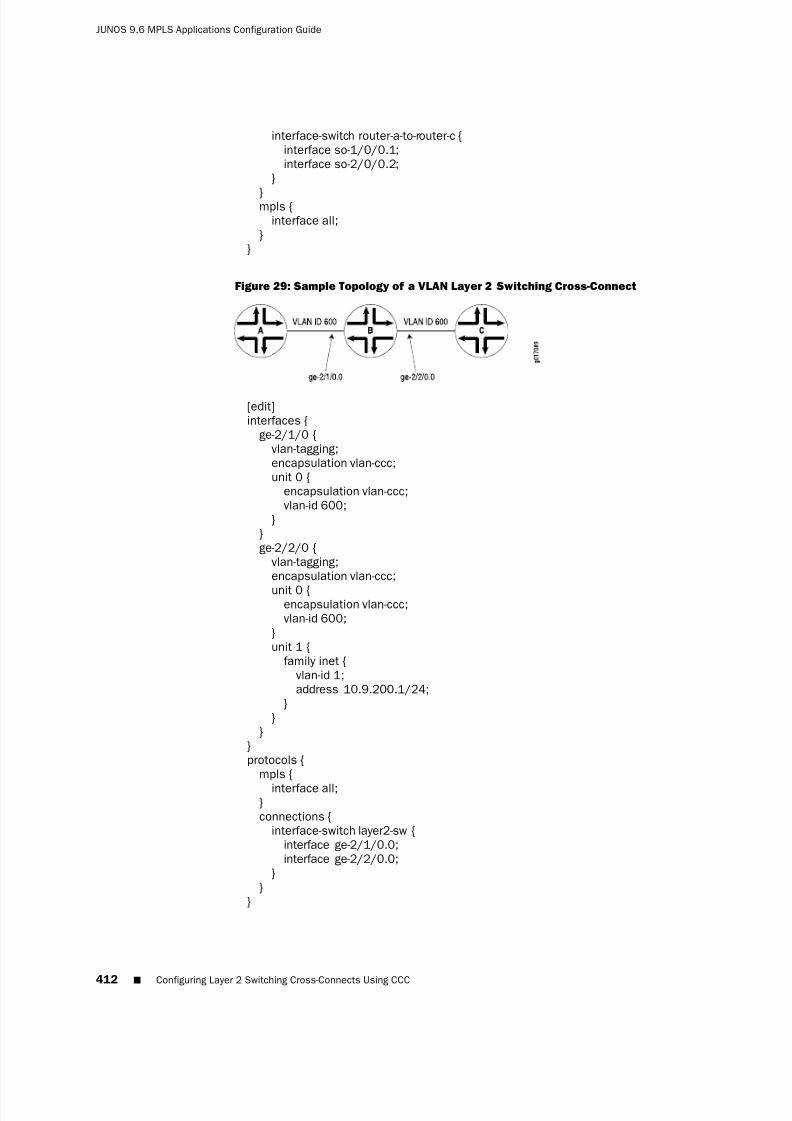
8/7/2019 Config Guide Mpls Applications
http://slidepdf.com/reader/full/config-guide-mpls-applications 450/547
interface-switch router-a-to-router-c {interface so-1/0/0.1;interface so-2/0/0.2;
}
}mpls {interface all;
}}
Figure 29: Sample Topology of a VLAN Layer 2 Switching Cross-Connect
[edit]interfaces {
ge-2/1/0 {vlan-tagging;encapsulation vlan-ccc;unit 0 {
encapsulation vlan-ccc;vlan-id 600;
}}ge-2/2/0 {
vlan-tagging;encapsulation vlan-ccc;
unit 0 {encapsulation vlan-ccc;vlan-id 600;
}unit 1 {
family inet {vlan-id 1;address 10.9.200.1/24;
}}
}}protocols {
mpls {
interface all;}connections {
interface-switch layer2-sw {interface ge-2/1/0.0;interface ge-2/2/0.0;
}}
}
412 ■ Configuring Layer 2 Switching Cross-Connects Using CCC
JUNOS 9.6 MPLS Applications Configuration Guide

8/7/2019 Config Guide Mpls Applications
http://slidepdf.com/reader/full/config-guide-mpls-applications 451/547
Configuring MPLS LSP Tunnel Cross-Connects Using CCC
MPLS tunnel cross-connects between interfaces and LSPs allow you to connect twodistant interface circuits of the same type by creating MPLS tunnels that use LSPs asthe conduit. The topology in Figure 30 on page 413 illustrates an MPLS LSP tunnelcross-connect. In this topology, two separate networks, in this case ATM accessnetworks, are connected through an IP backbone. CCC allows you to establish anLSP tunnel between the two domains. With LSP tunneling, you tunnel the ATM trafficfrom one network across a SONET backbone to the second network by using anMPLS LSP.
Figure 30: MPLS LSP Tunnel Cross-Connect
ERROR: Unresolved graphic fileref="g017093.eps" not found in"\\cmsxml\default\main\TechPubsWorkInProgress\STAGING\images\".
When traffic from Router A (VC 234) reaches Router B, it is encapsulated and placedinto an LSP, which is sent through the backbone to Router C. At Router C, the labelis removed, and the packets are placed onto the ATM permanent virtual circuit (PVC)(VC 591) and sent to Router D. Similarly, traffic from Router D (VC 591) is sent overan LSP to Router B, then placed on VC 234 to Router A.
You can configure LSP tunnel cross-connect on PPP, Cisco HDLC, Frame Relay, andATM circuits. In a single cross-connect, only like interfaces can be connected.
When you use MPLS tunnel cross-connects to support IS-IS, you must ensure thatthe LSP’s maximum transmission unit (MTU) can, at a minimum, accommodate a1492-octet IS-IS protocol data unit (PDU) in addition to the link-level overheadassociated with the technology being connected.
For the tunnel cross-connects to work, the IS-IS frame size on the edge routers(Routers A and D in Figure 30 on page 413) must be smaller than the LSP’s MTU.
NOTE: Frame size values do not include the frame check sequence (FCS) or delimitingflags.
To determine the LSP MTU required to support IS-IS, use the following calculation:
IS-IS MTU (minimum 1492, default 1497) + frame overhead + 4 (MPLS shim header)= Minimum LSP MTU
The framing overhead varies based on the encapsulation being used. The followinglists the IS-IS encapsulation overhead values for various encapsulations:
■ ATM
■ AAL5 multiplex—8 bytes (RFC 1483)
■ VC multiplex—0 bytes
■ Frame Relay
Configuring MPLS LSP Tunnel Cross-Connects Using CCC ■ 413
Chapter 18: CCC and TCC Configuration Guidelines

8/7/2019 Config Guide Mpls Applications
http://slidepdf.com/reader/full/config-guide-mpls-applications 452/547
■ Multiprotocol—2 bytes (RFCs 1490 and 2427)
■ VC multiplex—0 bytes
■ HDLC—4 bytes
■ PPP—4 bytes
■ VLAN—21 bytes (802.3/LLC)
For IS-IS to work over VLAN-CCC, the LSP’s MTU must be at least 1513 bytes (or1518 for 1497-byte PDUs). If you increase the size of a Fast Ethernet MTU above thedefault of 1500 bytes, you might need to explicitly configure jumbo frames onintervening equipment.
To modify the MTU, include the mtu statement when configuring the logical interfacefamily at the [edit interfaces interface-name unit logical-unit-number encapsulation family ]hierarchy level. For more information about setting the MTU, see the JUNOS Network Interfaces Configuration Guide.
To configure an LSP tunnel cross-connect, you must configure the following on theinterdomain router (Router B in Figure 30 on page 413):
■ Configuring the CCC Encapsulation for LSP Tunnel Cross-Connects on page 414
■ Configuring the CCC Connection for LSP Tunnel Cross-Connects on page 415
■ Example: Configuring an LSP Tunnel Cross-Connect on page 416
Configuring the CCC Encapsulation for LSP Tunnel Cross-Connects
To configure LSP tunnel cross-connects, you must configure the CCC encapsulationon the ingress and egress routers (Router B and Router C, respectively, in Figure 30
on page 413).
NOTE: You cannot configure families on CCC interfaces; that is, you cannot includethe family statement at the [edit interfaces interface-name unit logical-unit-number ]hierarchy level.
For PPP or Cisco HDLC circuits, include the encapsulation statement to configure theentire physical device. For these circuits to work, you must configure logical unit 0on the interface.
type-fpc /pic /port {
encapsulation (ppp-ccc | cisco-hdlc-ccc);unit 0;}
You can include these statements at the following hierarchy levels:
■ [edit interfaces]
■ [edit logical-systems logical-system-name interfaces]
414 ■ Configuring MPLS LSP Tunnel Cross-Connects Using CCC
JUNOS 9.6 MPLS Applications Configuration Guide

8/7/2019 Config Guide Mpls Applications
http://slidepdf.com/reader/full/config-guide-mpls-applications 453/547
For ATM circuits, specify the encapsulation when configuring the VC by includingthe following statements. For each VC, you configure whether it is a circuit or aregular logical interface.
at-fpc /pic /port {atm-options {vpi vpi-identifier maximum-vcs maximum-vcs;
}unit logical-unit-number {
point-to-point; # Default interface typeencapsulation atm-ccc-vc-mux;vci vpi-identifier .vci-identifier ;
}}
You can include these statements at the following hierarchy levels:
■ [edit interfaces]
■ [edit logical-systems logical-system-name interfaces]
For Frame Relay circuits, include the following statements to specify the encapsulationwhen configuring the DLCI. For each DLCI, you configure whether it is a circuit or aregular logical interface. The DLCI for regular interfaces must be in the range 1through 511. For CCC interfaces, it must be in the range 512 through 1022.
type-fpc /pic /port {encapsulation frame-relay-ccc;unit logical-unit-number {
point-to-point; # default interface typeencapsulation frame-relay-ccc;dlci dlci-identifier ;
}}
You can include these statements at the following hierarchy levels:
■ [edit interfaces]
■ [edit logical-systems logical-system-name interfaces]
For more information about the encapsulation statement, see the JUNOS Network Interfaces Configuration Guide.
Configuring the CCC Connection for LSP Tunnel Cross-Connects
To configure LSP tunnel cross-connects, include the remote-interface-switch statementto define the connection between the two circuits on the ingress and egress routers(Router B and Router C, respectively, in Figure 30 on page 413). The connection joinsthe interface or LSP that comes from the circuit’s source to the interface or LSP thatleads to the circuit’s destination. When you specify the interface name, include thelogical portion of the name, which corresponds to the logical unit number. For thecross-connect to be bidirectional, you must configure cross-connects on two routers.
remote-interface-switch connection-name {
Configuring MPLS LSP Tunnel Cross-Connects Using CCC ■ 415
Chapter 18: CCC and TCC Configuration Guidelines

8/7/2019 Config Guide Mpls Applications
http://slidepdf.com/reader/full/config-guide-mpls-applications 454/547
interface interface-name.unit-number ;transmit-lsp label-switched-path;receive-lsp label-switched-path;
}
You can include these statements at the following hierarchy levels:
■ [edit protocols connections]
■ [edit logical-systems logical-system-name protocols connections]
Example: Configuring an LSP Tunnel Cross-Connect
Configure a full-duplex MPLS LSP tunnel cross-connect from Router A to Router D,passing through Router B and Router C. See the topology in Figure 31 on page 416.
Figure 31: Example Topology of MPLS LSP Tunnel Cross-Connect
ERROR: Unresolved graphic fileref="g017094.eps" not found in"\\cmsxml\default\main\TechPubsWorkInProgress\STAGING\images\".
On Router B:
[edit]interfaces {
at-7/1/1 {atm-options {
vpi 1 maximum-vcs 600;}unit 1 {
point-to-point; # default interface type
encapsulation atm-ccc-vc-mux;vci 1.234;
}}
}protocols {
connections {remote-interface-switch router-b-to-router-c {
interface at-7/1/1.1;transmit-lsp lsp1;receive-lsp lsp2;
}}
}
On Router C:
[edit]interfaces {
at-3/0/0 {atm-options {
vpi 2 maximum-vcs 600;}unit 2 {
416 ■ Configuring MPLS LSP Tunnel Cross-Connects Using CCC
JUNOS 9.6 MPLS Applications Configuration Guide

8/7/2019 Config Guide Mpls Applications
http://slidepdf.com/reader/full/config-guide-mpls-applications 455/547
point-to-point; # default interface typeencapsulation atm-ccc-vc-mux;vci 2.591;
}
}}protocols {
connections {remote-interface-switch router-b-to-router-c {
interface at-3/0/0.2;transmit-lsp lsp2;receive-lsp lsp1;
}}
}
Configuring LSP Stitching Cross-Connects Using CCC
LSP stitching cross-connects “stitch” together LSPs to join two LSPs. For example,they stitch together LSPs that fall in two different traffic engineering database areas.The topology in Figure 32 on page 417 illustrates an LSP stitching cross-connect. Inthis topology, the network is divided into two traffic engineering domains. CCC allowsyou to establish an LSP between the two domains by stitching together LSPs fromthe two domains. For LSP stitching to work, the LSPs must be dynamic LSPs, notstatic.
Figure 32: LSP Stitching Cross-Connect
Without LSP stitching, a packet traveling from Router A to Router C is encapsulatedon Router A (the ingress router for the first LSP), decapsulated on Router B (the egressrouter), and then reencapsulated on Router B (the ingress router for the second LSP).With LSP stitching, you connect LSP1 and LSP2 into a single, stitched LSP, whichmeans that the packet is encapsulated once (on Router A) and decapsulated once(on Router C).
You can use LSP stitching to create a seamless LSP for LSPs carrying any kindof traffic.
To configure LSP stitching cross-connects, configure the two LSPs that you are stitchingtogether on the two ingress routers. Then on the interdomain router (Router B inFigure 32 on page 417), you define the connection between the two LSPs. Theconnection joins the LSP that comes from the connection’s source to the LSP thatleads to the connection’s destination.
protocols {connections {
Configuring LSP Stitching Cross-Connects Using CCC ■ 417
Chapter 18: CCC and TCC Configuration Guidelines

8/7/2019 Config Guide Mpls Applications
http://slidepdf.com/reader/full/config-guide-mpls-applications 456/547
lsp-switch connection-name {transmit-lsp label-switched-path;receive-lsp label-switched-path;
}
}}
You can configure these statements at the following hierarchy levels:
■ [edit protocols connections]
■ [edit logical-systems logical-system-name protocols connections]
Example: Configuring an LSP Stitching Cross-Connect
Configure a full-duplex LSP stitching cross-connect between Router A and Router C.To do this, you configure Router B, which is the interdomain router. See the topologyin Figure 33 on page 418.
Figure 33: Example Topology of LSP Stitching Cross-Connect
[edit]protocols {
connections interface-switch {
lsp-switch router-a-to-router-c {transmit-lsp lsp2;receive-lsp lsp1;
}}connections {
lsp-switch router-c-to-router-a {receive-lsp lsp3;transmit-lsp lsp4;
}}
}
Configuring TCC
This section describes how to configure translational cross-connect (TCC). Extensiveexamples on how to configure TCC for interface switching and for Layer 2.5 VPNsare available in the JUNOS Feature Guide.
418 ■ Configuring TCC
JUNOS 9.6 MPLS Applications Configuration Guide

8/7/2019 Config Guide Mpls Applications
http://slidepdf.com/reader/full/config-guide-mpls-applications 457/547
To configure TCC, you must perform the following tasks on the router that is actingas the switch:
■ Configuring the Encapsulation for Layer 2 Switching TCCs on page 419
■ Configuring the Connection for Layer 2 Switching TCCs on page 422■ Configuring MPLS for Layer 2 Switching TCCs on page 423
Configuring the Encapsulation for Layer 2 Switching TCCs
To configure a Layer 2 switching TCC, specify the TCC encapsulation on the desiredinterfaces of the router that is acting as the switch.
NOTE: You cannot configure standard protocol families on TCC or CCC interfaces.Only the CCC family is allowed on CCC interfaces, and only the TCC family is allowedon TCC interfaces.
For Ethernet circuits and Ethernet extended VLAN circuits, you must also configurethe Address Resolution Protocol (ARP). See “Configuring ARP for Ethernet andEthernet Extended VLAN Encapsulations” on page 422.
■ Configuring PPP and Cisco HDLC Encapsulation for Layer 2 SwitchingTCCs on page 419
■ Configuring ATM Encapsulation for Layer 2 Switching TCCs on page 420
■ Configuring Frame Relay Encapsulation for Layer 2 Switching TCCs on page 420
■ Configuring Ethernet Encapsulation for Layer 2 Switching TCCs on page 420
■ Configuring Ethernet Extended VLAN Encapsulation for Layer 2 SwitchingTCCs on page 421
■ Configuring ARP for Ethernet and Ethernet Extended VLANEncapsulations on page 422
Configuring PPP and Cisco HDLC Encapsulation for Layer 2 Switching TCCs
For PPP and Cisco HDLC circuits, configure the encapsulation type for the entirephysical device by specifying the appropriate value for the encapsulation statement.For these circuits to work, you must also configure the logical interface unit 0.
encapsulation (ppp-tcc | cisco-hdlc-tcc);unit 0;}
You can include these statements at the following hierarchy levels:
■ [edit interfaces interface-name]
■ [edit logical-systems logical-system-name interfaces interface-name]
Configuring TCC ■ 419
Chapter 18: CCC and TCC Configuration Guidelines

8/7/2019 Config Guide Mpls Applications
http://slidepdf.com/reader/full/config-guide-mpls-applications 458/547
Configuring ATM Encapsulation for Layer 2 Switching TCCs
For ATM circuits, configure the encapsulation type by specifying the appropriatevalue for the encapsulation statement in the virtual circuit (VC) configuration. Specifywhether each VC is a circuit or a regular logical interface.
atm-options {vpi vpi-identifier maximum-vcs maximum-vcs;
}unit logical-unit-number {
encapsulation (atm-tcc-vc-mux | atm-tcc-snap);point-to-point;vci vpi-identifier .vci-identifier ;
}
You can include these statements at the following hierarchy levels:
■
[edit interfaces at-fpc /pic /port]■ [edit logical-systems logical-system-name interfaces at-fpc /pic /port]
Configuring Frame Relay Encapsulation for Layer 2 Switching TCCs
For Frame Relay circuits, configure the encapsulation type by specifying the valueframe-relay-tcc for the encapsulation statement when configuring the data-linkconnection identifier (DLCI). You configure each DLCI as a circuit or a regular logicalinterface. The DLCI for regular interfaces must be in the range from 1 through 511,but for TCC and CCC interfaces it must be in the range from 512 through 1022.
encapsulation frame-relay-tcc;
unit logical-unit-number {point-to-point;encapsulation frame-relay-tcc;dlci dlci-identifier ;
}
You can include these statements at the following hierarchy levels:
■ [edit interfaces interface-name]
■ [edit logical-systems logical-system-name interfaces interface-name]
Configuring Ethernet Encapsulation for Layer 2 Switching TCCs
For Ethernet TCC circuits, configuring the encapsulation type for the entire physicaldevice by specifying the value ethernet-tcc for the encapsulation statement.
You must also specify static values for a remote address and a proxy address at the[edit interfaces interface-name unit unit-number family tcc] or [edit logical-systemslogical-system-name interfaces interface-name unit unit-number family tcc] hierarchylevel.
420 ■ Configuring TCC
JUNOS 9.6 MPLS Applications Configuration Guide

8/7/2019 Config Guide Mpls Applications
http://slidepdf.com/reader/full/config-guide-mpls-applications 459/547
The remote address is associated with the TCC switching router’s Ethernet neighbor;in the remote statement you must specify both the IP address and the media accesscontrol (MAC) address of the Ethernet neighbor. The proxy address is associated withthe TCC router’s other neighbor connected by the unlike link; in the proxy statement
you must specify the IP address of the non-Ethernet neighbor.
You can configure Ethernet TCC encapsulation for the interfaces on 1-port GigabitEthernet, 2-port Gigabit Ethernet, 4-port Fast Ethernet, and 4-port Gigabit EthernetPICs.
encapsulation ethernet-tcc;unit logical-unit-number {
family tcc {proxy {
inet-address ip-address;}remote {
inet-address ip-address;
mac-address mac-address;}
}}
You can include these statements at the following hierarchy levels:
■ [edit interfaces (fe | ge)-fpc /pic /port]
■ [edit logical-systems logical-system-name interfaces (fe | ge)-fpc /pic /port]
NOTE: For Ethernet circuits, you must also configure the Address Resolution Protocol(ARP). See “Configuring ARP for Ethernet and Ethernet Extended VLANEncapsulations” on page 422.
Configuring Ethernet Extended VLAN Encapsulation for Layer 2 Switching
TCCs
For Ethernet extended VLAN circuits, configure the encapsulation type for the entirephysical device by specifying the value extended-vlan-tcc for the encapsulationstatement.
You must also enable VLAN tagging. Ethernet interfaces in VLAN mode can havemultiple logical interfaces. With encapsulation type extended-vlan-tcc, all VLAN IDs
from 0 through 4094 are valid, up to a maximum of 1024 VLANs. As with Ethernetcircuits, you must also specify a proxy address and a remote address at the [editinterfaces interface-name unit logical-unit-number family tcc] or [edit logical-systemslogical-system-name interfaces interface-name unit unit-number family tcc] hierarchylevel (see “Configuring Ethernet Encapsulation for Layer 2 Switching TCCs” on page420).
encapsulation extended-vlan-tcc;vlan-tagging;unit logical-unit-number {
Configuring TCC ■ 421
Chapter 18: CCC and TCC Configuration Guidelines

8/7/2019 Config Guide Mpls Applications
http://slidepdf.com/reader/full/config-guide-mpls-applications 460/547
vlan-id identifier ;family tcc;proxy {
inet-address ip-address;
}remote {inet-address ip-address;mac-address mac-address;
}}
You can configure these statements at the following hierarchy levels:
■ [edit interfaces interface-name]
■ [edit logical-systems logical-system-name interfaces interface-name]
NOTE: For Ethernet extended VLAN circuits, you must also configure the AddressResolution Protocol (ARP). See “Configuring ARP for Ethernet and Ethernet ExtendedVLAN Encapsulations” on page 422.
Configuring ARP for Ethernet and Ethernet Extended VLAN Encapsulations
For Ethernet and Ethernet extended VLAN circuits with TCC encapsulation, you mustalso configure ARP. Because TCC simply removes one Layer 2 header and addsanother, the default form of dynamic ARP is not supported; you must configure staticARP.
Because remote and proxy addresses are specified on the router performing TCC
switching, you must apply the static ARP statement to the Ethernet-type interfacesof the routers that connect to the TCC-switched router. The arp statement must specifythe IP address and the MAC address of the remotely connected neighbor by use of the unlike Layer 2 protocol on the far side of the TCC switching router.
arp ip-address mac mac-address;
You can include this statement at the following hierarchy levels:
■ [edit interfaces interface-name unit logical-unit-number family inet address ip-address]
■ [edit logical-systems logical-system-name interfaces interface-name unitlogical-unit-number family inet address ip-address]
Configuring the Connection for Layer 2 Switching TCCs
You must configure the connection between the two circuits of the Layer 2 switchingTCC on the router acting as the switch. The connection joins the interface comingfrom the circuit’s source to the interface leading to the circuit’s destination. Whenyou specify the interface names, include the logical portion of the name, whichcorresponds to the logical unit number. The cross-connect is bidirectional, so packetsreceived on the first interface are transmitted from the second interface, and thosereceived on the second interface are transmitted from the first.
422 ■ Configuring TCC
JUNOS 9.6 MPLS Applications Configuration Guide

8/7/2019 Config Guide Mpls Applications
http://slidepdf.com/reader/full/config-guide-mpls-applications 461/547
To configure a connection for a local interface switch, include the followingstatements:
interface-switch connection-name {
interface interface-name.unit-number ;}lsp-switch connection-name {
transmit-lsp lsp-number ;receive-lsp lsp-number ;
}
You can include these statements at the following hierarchy levels:
■ [edit protocols connections]
■ [edit logical-systems logical-system-name protocols connections]
To configure a connection for a remote interface switch, include the following
statements:remote-interface-switch connection-name {
interface interface-name.unit-number ;interface interface-name.unit-number ;transmit-lsp lsp-number ;receive-lsp lsp-number ;
}
You can include these statements at the following hierarchy levels:
■ [edit protocols connections]
■ [edit logical-systems logical-system-name protocols connections]
Configuring MPLS for Layer 2 Switching TCCs
For a Layer 2 switching cross-connect to function, you need to configure MPLS.
To configure MPLS on an interface, configure a logical interface by including the unitstatement:
unit logical-unit-number ;
You can include this statement at the following hierarchy levels:
■ [edit interfaces interface-name]
■
[edit logical-systems logical-system-name interfaces interface-name]
To enable MPLS, include the interface statement:
interface (interface-name | all);
You can include this statement at the following hierarchy levels:
■ [edit protocols mpls]
Configuring TCC ■ 423
Chapter 18: CCC and TCC Configuration Guidelines

8/7/2019 Config Guide Mpls Applications
http://slidepdf.com/reader/full/config-guide-mpls-applications 462/547
■ [edit logical-systems logical-system-name protocols mpls]
NOTE: LSP link protection does not support TCC.
Configuring CCC and TCC Graceful Restart
To enable CCC and TCC graceful restart, include the graceful-restart statement:
graceful-restart;
You can include this statement at the following hierarchy levels:
■ [edit routing-options]
■ [edit logical-systems logical-system-name routing-options]
The graceful-restart statement enables graceful restart for all protocols supportingthis feature on the router. For more information about graceful restart, see the JUNOS Routing Protocols Configuration Guide.
CCC and TCC graceful restart depend on RSVP graceful restart. If you disable RSVPgraceful restart, CCC and TCC graceful restart will not work. For more informationabout RSVP graceful restart, see “RSVP Graceful Restart” on page 268 and “ConfiguringRSVP Graceful Restart” on page 289.
Configuring CCC Switching for Point-to-Multipoint LSPs
You can configure CCC to switch traffic from interfaces to point-to-multipoint LSPs.This feature is useful for handling multicast or broadcast traffic (for example, a digitalvideo stream).
To configure CCC switching for point-to-multipoint LSPs, you do the following:
■ On the ingress provider edge (PE) router, you configure CCC to switch trafficfrom an incoming interface to a point-to-multipoint LSP.
■ On the egress PE, you configure CCC to switch traffic from an incomingpoint-to-multipoint LSP to an outgoing interface.
The CCC connection for point-to-multipoint LSPs is unidirectional.
For more information on point-to-multipoint LSPs, see “Point-to-Multipoint LSPs” onpage 48 and “Point-to-Multipoint LSP Configuration Guidelines” on page 141.
To configure a CCC connection for a point-to-multipoint LSP, complete the steps inthe following sections:
■ Configuring the Point-to-Multipoint LSP Switch on Ingress PE Routers on page 425
■ Configuring the Point-to-Multipoint LSP Switch on Egress PE Routers on page 425
424 ■ Configuring CCC and TCC Graceful Restart
JUNOS 9.6 MPLS Applications Configuration Guide

8/7/2019 Config Guide Mpls Applications
http://slidepdf.com/reader/full/config-guide-mpls-applications 463/547
Configuring the Point-to-Multipoint LSP Switch on Ingress PE Routers
To configure the ingress PE router with a CCC switch for a point-to-multipoint LSP,include the p2mp-transmit-switch statement:
p2mp-transmit-switch switch-name {input-interface input-interface-name.unit-number ;transmit-p2mp-lsp transmitting-lsp;
}
You can include the p2mp-transmit-switch statement at the following hierarchy levels:
■ [edit protocols connections]
■ [edit logical-systems logical-system-name protocols connections]
switch-name specifies the name of the ingress CCC switch.
input-interface input-interface-name.unit-number specifies the name of the ingressinterface.
transmit-p2mp-lsp transmitting-lsp specifies the name of the transmittingpoint-to-multipoint LSP.
Configuring the Point-to-Multipoint LSP Switch on Egress PE Routers
To configure the CCC switch for a point-to-multipoint LSP on the egress PE router,include the p2mp-receive-switch statement.
p2mp-receive-switch switch-name {output-interface [ output-interface-name.unit-number ];receive-p2mp-lsp receptive-lsp;
}
You can include this statement at the following hierarchy levels:
■ [edit protocols connections]
■ [edit logical-systems logical-system-name protocols connections]
switch-name specifies the name of the egress CCC switch.
output-interface [ output-interface-name.unit-number ] specifies the name or one or
more egress interfaces.receive-p2mp-lsp receptive-lsp specifies the name of the receptive point-to-multipointLSP.
Configuring CCC Switching for Point-to-Multipoint LSPs ■ 425
Chapter 18: CCC and TCC Configuration Guidelines

8/7/2019 Config Guide Mpls Applications
http://slidepdf.com/reader/full/config-guide-mpls-applications 464/547
426 ■ Configuring CCC Switching for Point-to-Multipoint LSPs
JUNOS 9.6 MPLS Applications Configuration Guide

8/7/2019 Config Guide Mpls Applications
http://slidepdf.com/reader/full/config-guide-mpls-applications 465/547
Chapter 19
Summary of CCC and TCC ConfigurationStatements
This chapter provides a reference for each circuit cross-connect (CCC) configurationstatement. The statements are organized alphabetically.
■ 427

8/7/2019 Config Guide Mpls Applications
http://slidepdf.com/reader/full/config-guide-mpls-applications 466/547
connections
Syntax connections {interface-switch connection-name {
interface interface-name.unit-number ;}lsp-switch connection-name {
transmit-lsp label-switched-path;receive-lsp label-switched-path;
}p2mp-receive-switch {
output-interface [ interface-name.unit-number ];receive-p2mp-lsp receiving-point-to-multipoint-lsp;
}p2mp-transmit-switch {
input-interface interface-name.unit-number ;transmit-p2mp-lsp transmitting-point-to-multipoint-lsp;}remote-interface-switch connection-name {
interface interface-name.unit-number ;receive-lsp label-switched-path;transmit-lsp label-switched-path;
}}
Hierarchy Level [edit logical-systems logical-system-name protocols],[edit protocols]
Release Information
Statement introduced before JUNOS Release 7.4.Description Define the connection between two circuits in a CCC connection.
Options The statements are explained separately.
Usage Guidelines See “CCC and TCC Configuration Guidelines” on page 405 and the JUNOS Network Interfaces Configuration Guide.
Required Privilege Level routing—To view this statement in the configuration.routing-control—To add this statement to the configuration.
428 ■ connections
JUNOS 9.6 MPLS Applications Configuration Guide

8/7/2019 Config Guide Mpls Applications
http://slidepdf.com/reader/full/config-guide-mpls-applications 467/547
encapsulation
See the following sections:
■ encapsulation (Logical Interface) on page 430
■ encapsulation (Physical Interface) on page 433
connections ■ 429
Chapter 19: Summary of CCC and TCC Configuration Statements
8/7/2019 Config Guide Mpls Applications
http://slidepdf.com/reader/full/config-guide-mpls-applications 468/547
encapsulation (Logical Interface)
Syntax encapsulation (atm-ccc-cell-relay | atm-ccc-vc-mux | atm-tcc-vc-mux | atm-cisco-nlpid |
tm-mlppp-llc | atm-nlpid | atm-ppp-llc | atm-ppp-vc-mux | atm-snap | atm-tcc-snap |atm-vc-mux | ether-over-atm-llc | ether-vpls-over-atm-llc | frame-relay-ccc | frame-relay-ppp |frame-relay-tcc | gre-fragmentation | multilink-frame-relay-end-to-end | multilink-ppp |ppp-over-ether | ppp-over-ether-over-atm-llc | vlan-ccc | vlan-ccc | vlan-vpls);
Hierarchy Level [edit interfaces interface-name unit logical-unit-number ],[edit logical-systems logical-system-name interfaces interface-name unit logical-unit-number ]
Release Information Statement introduced before JUNOS Release 7.4.
Description Logical link-layer encapsulation type.
Options atm-ccc-cell-relay—Use ATM cell-relay encapsulation.
atm-ccc-vc-mux—Use ATM VC multiplex encapsulation on circuit cross-connect (CCC)circuits. When you use this encapsulation type, you can configure the family ccconly.
atm-cisco-nlpid—Use Cisco ATM NLPID encapsulation. When you use this encapsulationtype, you can configure the family inet only.
atm-mlppp-llc—For ATM2 IQ interfaces only, use Multilink PPP over ATM adaptationlayer 5 (AAL5) logical link control (LLC). For this encapsulation type, your routermust be equipped with a Link Services PIC.
atm-nlpid—Use ATM NLPID encapsulation. When you use this encapsulation type,you can configure the family inet only.
atm-ppp-llc—For ATM2 IQ interfaces only, use PPP over ATM adaptation layer 5(AAL5) logical link control (LLC) encapsulation.
atm-ppp-vc-mux—For ATM2 IQ interfaces only, use PPP over ATM adaptation layer 5(AAL5) multiplex encapsulation.
atm-snap—Use ATM SNAP encapsulation.
atm-tcc-snap—Use ATM SNAP encapsulation on translational cross-connect (TCC)circuits.
atm-tcc-vc-mux—Use ATM VC multiplex encapsulation on translational cross-connect
(TCC) circuits. When you use this encapsulation type, you can configure thefamily tcc only.
atm-vc-mux—Use ATM VC multiplex encapsulation. When you use this encapsulationtype, you can configure the family inet only.
ether-over-atm-llc—For interfaces that carry IPv4 traffic, use Ethernet over ATM LLCencapsulation. When you use this encapsulation type, you cannot configuremultipoint interfaces.
430 ■ encapsulation (Logical Interface)
JUNOS 9.6 MPLS Applications Configuration Guide

8/7/2019 Config Guide Mpls Applications
http://slidepdf.com/reader/full/config-guide-mpls-applications 469/547
ether-vpls-over-atm-llc—For ATM intelligent queuing interfaces only, use the EthernetVPLS over ATM LLC encapsulation to bridge Ethernet interfaces and ATMinterfaces over a VPLS routing instance (as described in RFC 2684). Packets fromthe ATM interfaces are converted to standard ENET2/802.3 encapsulated Ethernet
frames with the FCS field removed.
frame-relay-ccc—Use Frame Relay encapsulation on CCC circuits. When you use thisencapsulation type, you can configure the family ccc only.
frame-relay-ppp—Use Frame Relay encapsulation on PPP circuits.
frame-relay-tcc—Use Frame Relay encapsulation on TCC circuits for connecting unlikemedia. When you use this encapsulation type, you can configure the family tcconly.
gre-fragmentation—For adaptive services interfaces only, use GRE fragmentationencapsulation to enable fragmentation of IPv4 packets in GRE tunnels. This
encapsulation clears the don’
t fragment (DF) bit in the packet header. If thepacket’s size exceeds the tunnel’s maximum transmission unit (MTU) value, thepacket is fragmented before encapsulation.
multilink-frame-relay-end-to-end—Use Multilink Frame Relay (MLFR) FRF.15encapsulation. This encapsulation is used only on multilink and link servicesinterfaces and their constituent T1 or E1 interfaces.
multilink-ppp—Use Multilink Point-to-Point Protocol (MLPPP) encapsulation. Thisencapsulation is used only on multilink and link services interfaces and theirconstituent T1 or E1 interfaces.
ppp-over-ether—For underlying Ethernet interfaces on J Series Services Routers only,use PPP over Ethernet encapsulation. When you use this encapsulation type,you cannot configure the interface address. Instead, configure the interfaceaddress on the PPP interface.
ppp-over-ether-over-atm-llc—For underlying ATM interfaces on J Series Services Routersonly, use PPP over Ethernet over ATM LLC encapsulation. When you use thisencapsulation type, you cannot configure the interface address. Instead, youconfigure the interface address on the PPP interface.
vlan-ccc—Use Ethernet virtual local area network (VLAN) encapsulation on CCCcircuits. When you use this encapsulation type, you can configure the family ccconly.
vlan-tcc—Use Ethernet VLAN encapsulation on TCC circuits. When you use this
encapsulation type, you can configure the family tcc only.
vlan-vpls—Use Ethernet VLAN encapsulation on virtual private LAN service (VPLS)circuits.
encapsulation (Logical Interface) ■ 431
Chapter 19: Summary of CCC and TCC Configuration Statements

8/7/2019 Config Guide Mpls Applications
http://slidepdf.com/reader/full/config-guide-mpls-applications 470/547
Usage Guidelines See “Configuring the CCC Encapsulation for Layer 2 Switching Cross-Connects” onpage 406, “Configuring the CCC Encapsulation for LSP Tunnel Cross-Connects” onpage 414, and “Configuring the Encapsulation for Layer 2 Switching TCCs” on page419. For more information about how to configure interfaces, see the JUNOS Network
Interfaces Configuration Guide.
Required Privilege Level interface—To view this statement in the configuration.interface-control—To add this statement to the configuration.
432 ■ encapsulation (Logical Interface)
JUNOS 9.6 MPLS Applications Configuration Guide

8/7/2019 Config Guide Mpls Applications
http://slidepdf.com/reader/full/config-guide-mpls-applications 471/547
encapsulation (Physical Interface)
Syntax encapsulation (atm-ccc-cell-relay | atm-pvc | cisco-hdlc | cisco-hdlc-ccc | cisco-hdlc-tcc |
ethernet-ccc | ethernet-over-atm | ethernet-tcc | ethernet-vpls | extended-frame-relay-ccc |extended-frame-relay-tcc | extended-vlan-ccc | extended-vlan-tcc | extended-vlan-vpls |flexible-ethernet-services | flexible-frame-relay | frame-relay | frame-relay-ccc |frame-relay-tcc | frame-relay-port-ccc | multilink-frame-relay-uni-nni | ppp | ppp-ccc |ppp-tcc | vlan-ccc | vlan-vpls);
Hierarchy Level [edit interfaces interface-name]
Release Information Statement introduced before JUNOS Release 7.4.
Description Physical link-layer encapsulation type.
Default PPP encapsulation.
Options atm-ccc-cell-relay—Use ATM cell-relay encapsulation.
atm-pvc—Use ATM PVC encapsulation.
cisco-hdlc—Use Cisco-compatible HDLC framing.
cisco-hdlc-ccc—Use Cisco-compatible HDLC framing on CCC circuits.
cisco-hdlc-tcc—Use Cisco-compatible HDLC framing on TCC circuits for connectingunlike media.
ethernet-ccc—Use Ethernet CCC encapsulation on Ethernet interfaces that must acceptpackets carrying standard TPID values.
ethernet-over-atm—As defined in RFC 1483, this encapsulation type allows ATMinterfaces to connect to devices that support only bridged-mode protocol dataunits (PDUs). The JUNOS Software does not completely support bridging, butaccepts BPDU packets as a default gateway. If you use the router as an edgedevice, then the router acts as a default gateway. It accepts Ethernet LLC/SNAPframes with IP or ARP in the payload and drops the rest. For packets destinedthe Ethernet LAN, a route lookup is done by use of the destination IP address.If the route lookup yields a full address match, the packet is encapsulated withan LLC/SNAP and MAC header, and the packet is forwarded to the ATM interface.
ethernet-tcc—For interfaces that carry IPv4 traffic, use Ethernet TCC encapsulationon interfaces that must accept packets carrying standard Tag Protocol Identifier
(TPID) values. Ethernet TCC is not currently supported on Fast Ethernet 48-portPICs.
ethernet-vpls—Use Ethernet VPLS encapsulation on Ethernet interfaces that haveVPLS enabled and that must accept packets carrying standard TPID values.
extended-frame-relay-ccc—Use Frame Relay encapsulation on CCC circuits. Thisencapsulation type allows you to dedicate DLCIs 1 through 1022 to CCC.
encapsulation (Physical Interface) ■ 433
Chapter 19: Summary of CCC and TCC Configuration Statements

8/7/2019 Config Guide Mpls Applications
http://slidepdf.com/reader/full/config-guide-mpls-applications 472/547
extended-frame-relay-tcc—Use Frame Relay encapsulation on TCC circuits to connectunlike media. This encapsulation type allows you to dedicate DLCIs 1 through1022 to TCC.
extended-vlan-ccc—Use extended VLAN encapsulation on CCC circuits with GigabitEthernet and 4-port Fast Ethernet interfaces that must accept packets carrying802.1Q values.
extended-vlan-tcc—For interfaces that carry IPv4 traffic, use extended VLANencapsulation on TCC circuits with Gigabit Ethernet interfaces on which youwant to use 802.1Q tagging. Extended Ethernet TCC is not currently supportedon Fast Ethernet 48-port PICs.
extended-vlan-vpls—Use extended VLAN VPLS encapsulation on Ethernet interfacesthat have VLAN 802.1Q tagging and VPLS enabled and that must accept packetscarrying TPIDs 0x8100, 0x9100, and 0x9901.
flexible-ethernet-services—
For Gigabit Ethernet intelligent queuing interfaces only,use flexible Ethernet services encapsulation when you want to configure multipleper-unit Ethernet encapsulations. This encapsulation type allows you to configureany combination of routed, TCC, CCC, and VPLS encapsulations on a singlephysical port.
flexible-frame-relay—For intelligent queuing interfaces only, use flexible Frame Relayencapsulation when you want to configure multiple per-unit Frame Relayencapsulations. This encapsulation type allows you to configure any combinationof TCC, CCC, or standard Frame Relay encapsulations on a single physical port.Also, each logical interface can have any DLCI value in the range 1 through 1022.
frame-relay—Use Frame Relay encapsulation.
frame-relay-ccc—Use plain Frame Relay encapsulation or Frame Relay encapsulationon circuit cross-connect (CCC) circuits.
frame-relay-port-ccc—Use Frame Relay port CCC encapsulation to transparently carryall the DLCIs between two CE routers without explicitly configuring each DLCIon the two PE routers with Frame Relay transport. When you use thisencapsulation type, you can configure the family ccc only.
frame-relay-tcc—Use Frame Relay encapsulation on TCC circuits to connect unlikemedia.
multilink-frame-relay-uni-nni—Use MLFR user-to-network (UNI) network-to-network(NNI) encapsulation. This encapsulation is used only on link services interfaces
functioning as FRF.16 bundles and their constituent T1 or E1 interfaces.
ppp—Use serial PPP encapsulation.
ppp-ccc—Use serial PPP encapsulation on CCC circuits. When you use thisencapsulation type, you can configure the family ccc only.
ppp-tcc—Use serial PPP encapsulation on TCC circuits for connecting unlike media.When you use this encapsulation type, you can configure the family tcc only.
434 ■ encapsulation (Physical Interface)
JUNOS 9.6 MPLS Applications Configuration Guide

8/7/2019 Config Guide Mpls Applications
http://slidepdf.com/reader/full/config-guide-mpls-applications 473/547
vlan-ccc—Use Ethernet VLAN encapsulation on CCC circuits.
vlan-vpls—Use VLAN VPLS encapsulation on Ethernet interfaces with VLAN taggingand VPLS enabled. Interfaces with VLAN VPLS encapsulation accept packets
carrying standard TPID values only.
Usage Guidelines See “Configuring the CCC Encapsulation for Layer 2 Switching Cross-Connects” onpage 406, “Configuring the CCC Encapsulation for LSP Tunnel Cross-Connects” onpage 414, and “Configuring the Encapsulation for Layer 2 Switching TCCs” on page419. For more information about how to configure interfaces, see the JUNOS Network Interfaces Configuration Guide.
Required Privilege Level interface—To view this statement in the configuration.interface-control—To add this statement to the configuration.
interface-switch
Syntax interface-switch connection-name {interface interface-name.unit-number ;
}
Hierarchy Level [edit logical-systems logical-system-name protocols connections],[edit protocols connections]
Release Information Statement introduced before JUNOS Release 7.4.
Description Configure Layer 2 switching cross-connects. The cross-connect is bidirectional, sopackets received on the first interface are transmitted out the second interface, andthose received on the second interface are transmitted out the first.
For Layer 2 switching cross-connects to work, you must also configure MPLS.
Options connection-name—Connection name.
interface interface-name.unit-number —Interface name. Include the logical portion of the name, which corresponds to the logical unit number.
Usage Guidelines See “Configuring the CCC Connection for Layer 2 Switching Cross-Connects” on page410.
Required Privilege Level routing—To view this statement in the configuration.routing-control—To add this statement to the configuration
interface-switch ■ 435
Chapter 19: Summary of CCC and TCC Configuration Statements

8/7/2019 Config Guide Mpls Applications
http://slidepdf.com/reader/full/config-guide-mpls-applications 474/547
lsp-switch
Syntax lsp-switch connection-name {transmit-lsp label-switched-path;receive-lsp label-switched-path;
}
Hierarchy Level [edit logical-systems logical-system-name protocols connections],[edit protocols connections]
Release Information Statement introduced before JUNOS Release 7.4.
Description Configure Layer 2 switching cross-connects.
Options connection-name—Connection name.
receive-lsp label-switched-path—Name of the LSP from the connection’s source.
transmit-lsp label-switched-path—Name of the LSP to the connection’s destination.
Usage Guidelines See “CCC and TCC Configuration Guidelines” on page 405, “Configuring LSP StitchingCross-Connects Using CCC” on page 417, and “Configuring the Connection for Layer 2Switching TCCs” on page 422.
Required Privilege Level routing—To view this statement in the configuration.routing-control—To add this statement to the configuration.
436 ■ lsp-switch
JUNOS 9.6 MPLS Applications Configuration Guide

8/7/2019 Config Guide Mpls Applications
http://slidepdf.com/reader/full/config-guide-mpls-applications 475/547
p2mp-receive-switch
Syntax p2mp-receive-switch point-to-multipoint-switch-name {output-interface [ interface-name.unit-number ];receive-p2mp-lsp receiving-point-to-multipoint-lsp;
}
Hierarchy Level [edit logical-systems logical-system-name protocols connections],[edit protocols connections]
Release Information Statement introduced before JUNOS Release 7.4.
Description Configure the CCC switch for a point-to-multipoint LSP on the egress PE router.
Options point-to-multipoint-switch-name—Point-to-multipoint CCC receive switch name.
output-interface interface-name.unit-number —Name of the egress interfaces for thepoint-to-multipoint LSP traffic. You can configure multiple output interfaces.
receive-p2mp-lsp receiving-point-to-multipoint-lsp—Name of the point-to-multipoint LSPthat is switched to the output interface.
Usage Guidelines See “Configuring the Point-to-Multipoint LSP Switch on Egress PE Routers” on page425.
Required Privilege Level routing—To view this statement in the configuration.routing-control—To add this statement to the configuration.
p2mp-receive-switch ■ 437
Chapter 19: Summary of CCC and TCC Configuration Statements

8/7/2019 Config Guide Mpls Applications
http://slidepdf.com/reader/full/config-guide-mpls-applications 476/547
p2mp-transmit-switch
Syntax p2mp-transmit-switch point-to-multipoint-transmit-switch-name {input-interface interface-name.unit-number ;transmit-p2mp-lsp interface-name.unit-number ;
}
Hierarchy Level [edit logical-systems logical-system-name protocols connections],[edit protocols connections]
Release Information Statement introduced before JUNOS Release 7.4.
Description Configure the CCC switch for the point-to-multipoint LSP on the ingress PE router.
Options point-to-multipoint-transmit-switch-name—Point-to-multipoint CCC transmit switch
name.
input-interface input-interface-name.unit-number —Specify the name of the interfacecarrying incoming traffic to be switched to the point-to-multipoint LSP.
transmit-p2mp-lsp transmitting-point-to-multipoint-lsp—Specify the name of thepoint-to-multipoint LSP carrying traffic to the CCC switch on the egress PE router.
Usage Guidelines See “Configuring the Point-to-Multipoint LSP Switch on Ingress PE Routers” on page425.
Required Privilege Level routing—To view this statement in the configuration.routing-control—To add this statement to the configuration.
438 ■ p2mp-transmit-switch
JUNOS 9.6 MPLS Applications Configuration Guide

8/7/2019 Config Guide Mpls Applications
http://slidepdf.com/reader/full/config-guide-mpls-applications 477/547
remote-interface-switch
Syntax remote-interface-switch connection-name {interface interface-name.unit-number ;transmit-lsp label-switched-path;receive-lsp label-switched-path;
}
Hierarchy Level [edit logical-systems logical-system-name protocols connections],[edit protocols connections]
Release Information Statement introduced before JUNOS Release 7.4.
Description Configure MPLS LSP tunnel cross-connects.
Options connection-name—Connection name.
interface interface-name.unit-number —Interface name. Include the logical portion of the name, which corresponds to the logical unit number.
receive-lsp label-switched-path—Name of the LSP from the connection’s source.
transmit-lsp label-switched-path—Name of the LSP to the connection’s destination.
Usage Guidelines See “CCC and TCC Configuration Guidelines” on page 405 and “Configuring MPLSLSP Tunnel Cross-Connects Using CCC” on page 413.
Required Privilege Level routing—To view this statement in the configuration.
routing-control—
To add this statement to the configuration.
remote-interface-switch ■ 439
Chapter 19: Summary of CCC and TCC Configuration Statements

8/7/2019 Config Guide Mpls Applications
http://slidepdf.com/reader/full/config-guide-mpls-applications 478/547
440 ■ remote-interface-switch
JUNOS 9.6 MPLS Applications Configuration Guide

8/7/2019 Config Guide Mpls Applications
http://slidepdf.com/reader/full/config-guide-mpls-applications 479/547
Part 6
GMPLS
■ GMPLS Overview on page 443
■ GMPLS Configuration Guidelines on page 449
■ Hierarchy of RSVP LSPs Configuration Guidelines on page 465
■ Summary of GMPLS Configuration Statements on page 471
GMPLS ■ 441

8/7/2019 Config Guide Mpls Applications
http://slidepdf.com/reader/full/config-guide-mpls-applications 480/547
442 ■ GMPLS
JUNOS 9.6 MPLS Applications Configuration Guide
8/7/2019 Config Guide Mpls Applications
http://slidepdf.com/reader/full/config-guide-mpls-applications 481/547

8/7/2019 Config Guide Mpls Applications
http://slidepdf.com/reader/full/config-guide-mpls-applications 482/547
■ Internet draft draft-ietf-ccamp-lmp-10.txt, Link Management Protocol (LMP) (expiresApril 2004)
■ Internet draft draft-ietf-ccamp-ospf-gmpls-extensions-04.txt, OSPF Extensions inSupport of Generalized MPLS (expires August 2002), (except Link Local/RemoteIdentifiers, Link Protection Type, Shared Risk Link Group (SRLG), and Implicationsof Graceful Restart)
The interface switching capability descriptor described in Section 6.4 is implemented;however, it is currently packet-switch capable only.
■ Internet draft draft-ietf-mpls-bundle-04.txt, Link Bundling in MPLS Traffic Engineering
To access RFCs and drafts, go to the IETF website at http://www.ietf.org/.
Terms and Acronyms
F
Forwarding adjacency A forwarding path for sending data between GMPLS-enabled devices.
G
Generalized MPLS
(GMPLS)
An extension to MPLS that allows data from multiple layers to be switched overlabel-switched paths (LSPs). GMPLS LSP connections are possible between similarLayer 1, Layer 2, and Layer 3 devices.
GMPLS label Layer 3 identifiers, fiber port, time-division multiplexing (TDM) time slot, or densewavelength-division multiplexing (DWDM) wavelength of a GMPLS-enabled deviceused as a next-hop identifier.
GMPLS LSP types The four types of GMPLS LSPs are:
■ Fiber-switched capable (FSC)—LSPs are switched between two fiber-baseddevices, such optical cross-connects (OXCs) that operate at the level of individualfibers.
■ Lambda-switched capable (LSC)—LSPs are switched between two DWDM devices,such as such as OXCs that operate at the level of individual wavelengths.
■ TDM-switched capable (TDM)—LSPs are switched between two TDM devices,
such as SONET ADMs.
■ Packet-switched capable (PSC)—LSPs are switched between two packet-baseddevices, such as routers or ATM switches.
L
444 ■ Terms and Acronyms
JUNOS 9.6 MPLS Applications Configuration Guide

8/7/2019 Config Guide Mpls Applications
http://slidepdf.com/reader/full/config-guide-mpls-applications 483/547

8/7/2019 Config Guide Mpls Applications
http://slidepdf.com/reader/full/config-guide-mpls-applications 484/547
NOTE: There is not necessarily a one-to-one correspondence between a physicalinterface and a GMPLS interface. If a GMPLS connection uses a nonchannelizedphysical connector, the GMPLS label can use the physical port ID. However, the label
for channelized interfaces often is based on a channel or time slot. Consequently, itis best to refer to GMPLS labels as identifiers for a resource on a traffic engineeringlink.
To establish LSPs, GMPLS uses the following mechanisms:
■ An out-of-band control channel and a data channel—RSVP messages for LSPsetup are sent over an out-of-band control network. Once the LSP setup iscomplete and the path is provisioned, the data channel is up and can be usedto carry traffic. The Link Management Protocol (LMP) is used to define andmanage the data channels between a pair of nodes. You can optionally use LMPto establish and maintain LMP control channels between peers running the same
JUNOS Software release.
■ RSVP-TE extensions for GMPLS—RSVP-TE is already designed to signal the setupof packet LSPs. This has been extended for GMPLS to be able to request pathsetup for various kinds of LSPs (nonpacket) and request labels like wavelengths,time slots, and fibers as label objects.
■ Bidirectional LSPs—Data can travel both ways between GMPLS devices over asingle path, so nonpacket LSPs are signaled to be bidirectional.
GMPLS Operation
The basic functionality of GMPLS requires close interaction between RSVP and LMP.It works in the following sequence:
1. LMP notifies RSVP of the new entities:
■ Traffic engineering link (forwarding adjacency)
■ Resources available for the traffic engineering link
■ Control peer
2. GMPLS extracts the LSP attributes from the configuration and requests RSVP tosignal one or more specific paths, which are specified by the traffic engineeringlink addresses.
3. RSVP determines the local traffic engineering link, corresponding controladjacency and active control channel, and transmission parameters (such as IP
destination). It requests that LMP allocate a resource from the traffic engineeringlink with the specified attributes. If LMP finds a resource matching the attributes,label allocation succeeds. RSVP sends a PathMsg hop by hop until it reaches thetarget router.
4. When the target router receives the PathMsg, RSVP again requests that LMPallocate a resource based on the signaled parameters. If label allocation succeeds,the router sends back a ResvMsg.
5. If the signaling is successful, a bidirectional optical path is provisioned.
446 ■ GMPLS Operation
JUNOS 9.6 MPLS Applications Configuration Guide

8/7/2019 Config Guide Mpls Applications
http://slidepdf.com/reader/full/config-guide-mpls-applications 485/547

8/7/2019 Config Guide Mpls Applications
http://slidepdf.com/reader/full/config-guide-mpls-applications 486/547
■ An out-of-band control plane makes it possible to signal LSP path setup.
■ RSVP-TE extensions support additional objects beyond Layer 3 packets, such asports, time slots, and wavelengths.
■ The LMP protocol creates and maintains a database of traffic engineering linksand peer information. Only the static version of this protocol is supported in the
JUNOS Software. You can optionally configure LMP to establish and maintainLMP control channels between peers running the same JUNOS Software release.
■ Bidirectional LSPs are required between devices.
■ Several GMPLS label types that are defined in RFC 3471, Generalized MPLS —Signaling Functional Description, such as MPLS, Generalized, SONET/SDH,Suggested, and Upstream, are supported. Generalized labels do not contain atype field, because the nodes should know from the context of their connectionwhat type of label to expect.
■ Traffic parameters facilitate GMPLS bandwidth encoding and SONET/SDHformatting.
■ Other supported attributes include interface identification and errored interfaceidentification, user-to-network (UNI)-style signaling, and secondary LSP paths.
448 ■ GMPLS Features
JUNOS 9.6 MPLS Applications Configuration Guide
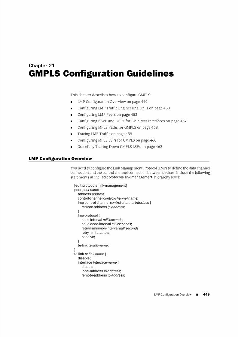
8/7/2019 Config Guide Mpls Applications
http://slidepdf.com/reader/full/config-guide-mpls-applications 487/547
Chapter 21
GMPLS Configuration Guidelines
This chapter describes how to configure GMPLS:
■ LMP Configuration Overview on page 449
■ Configuring LMP Traffic Engineering Links on page 450
■ Configuring LMP Peers on page 452
■ Configuring RSVP and OSPF for LMP Peer Interfaces on page 457
■ Configuring MPLS Paths for GMPLS on page 458
■ Tracing LMP Traffic on page 459
■ Configuring MPLS LSPs for GMPLS on page 460
■ Gracefully Tearing Down GMPLS LSPs on page 462
LMP Configuration Overview
You need to configure the Link Management Protocol (LMP) to define the data channelconnection and the control channel connection between devices. Include the following
statements at the [edit protocols link-management] hierarchy level:
[edit protocols link-management]peer peer-name {
address address;control-channel control-channel-name;lmp-control-channel control-channel-interface {
remote-address ip-address;}lmp-protocol {
hello-interval milliseconds;hello-dead-interval milliseconds;retransmission-interval milliseconds;retry-limit number ;
passive;}te-link te-link-name;
}te-link te-link-name {
disable;interface interface-name {
disable;local-address ip-address;remote-address ip-address;
LMP Configuration Overview ■ 449

8/7/2019 Config Guide Mpls Applications
http://slidepdf.com/reader/full/config-guide-mpls-applications 488/547
remote-id id-number ;}label-switched-path lsp-name;local-address ip-address;
remote-address ip-address;remote-id id-number ;}traceoptions {
file filename <files number > <size size> <world-readable | no-world-readable>;flag flag <flag-modifier > <disable>;
}
NOTE: Although you can include GMPLS configuration statements at the [editlogical-systems logical-system-name] hierarchy level, GMPLS is not supported on logicalsystems.
For information about configuring LMP, see the following sections:
■ Configuring LMP Traffic Engineering Links on page 450
■ Configuring LMP Peers on page 452
■ Configuring RSVP and OSPF for LMP Peer Interfaces on page 457
■ Configuring MPLS Paths for GMPLS on page 458
■ Tracing LMP Traffic on page 459
Configuring LMP Traffic Engineering Links
An LMP traffic engineering link acts as a data channel connection between GMPLSdevices.
To configure a traffic engineering link, include the te-link statement at the [editprotocols link-management] hierarchy level:
[edit protocols link-management]te-link te-link-name {
disable;interface interface-name {
local-address ip-address;remote-address ip-address;remote-id id-number ;
}
label-switched-path lsp-name;local-address ip-address;remote-address ip-address;remote-id id-number ;
}
450 ■ Configuring LMP Traffic Engineering Links
JUNOS 9.6 MPLS Applications Configuration Guide

8/7/2019 Config Guide Mpls Applications
http://slidepdf.com/reader/full/config-guide-mpls-applications 489/547
Complete the procedures in the following sections to configure an LMP trafficengineering link:
■ Configuring the Local IP Address for Traffic Engineering Links on page 451
■ Configuring the Remote IP Address for Traffic Engineering Links on page 451■ Configuring the Remote ID for Traffic Engineering Links on page 452
When you configure a traffic engineering link that contains interfaces for an LMPpeer, you must also configure a control channel. However, no control channel isrequired for a traffic engineering link that contains an LSP. For information onconfiguring control channels, see “Configuring LMP Peers” on page 452.
Configuring the Local IP Address for Traffic Engineering Links
Use the local-address statement to configure the local IP address associated with thetraffic engineering link.
We recommend that you configure an IP address subnet for your traffic engineeringlink addresses that is different from the subnet configured for your physical interfaces.This configuration enables you to identify which addresses are physical and whichaddresses belong to the traffic engineering link.
To configure the local IP address for the traffic engineering link, include thelocal-address statement:
te-link te-link-name {interface interface-name {
local-address ip-address;}local-address ip-address;
}
For a list of hierarchy levels at which you can include this statement, see the statementsummary section for this statement.
Configuring the Remote IP Address for Traffic Engineering Links
You need to specify the address of the remote end of the data channel for each trafficengineering link. Use the remote-address statement to configure the remote IP address.
We recommend that you configure an IP address subnet for your traffic engineeringlink addresses that is different from the subnet configured for your physical interfaces.This enables you to identify which addresses are physical and which addresses belong
to the traffic engineering link.
To configure the remote IP address for the traffic engineering link, include theremote-address statement:
te-link te-link-name {interface interface-name {
remote-address ip-address;}remote-address ip-address;
Configuring LMP Traffic Engineering Links ■ 451
Chapter 21: GMPLS Configuration Guidelines

8/7/2019 Config Guide Mpls Applications
http://slidepdf.com/reader/full/config-guide-mpls-applications 490/547
}
For a list of hierarchy levels at which you can include this statement, see the statementsummary section for this statement.
Configuring the Remote ID for Traffic Engineering Links
The local ID for the traffic engineering link is automatically assigned by LMP. Theport identifier and labels for the interfaces (resources) in the traffic engineering linkare also assigned automatically. However, you need to explicitly configure the remoteID for the traffic engineering link and the remote ID traffic engineering link interface.The remote ID for the interface must be based on the post-ID assignment of the peernode. The remote IDs are needed for static mapping of remote labels to local labels.
Before you can obtain the remote IDs for the traffic engineering link and trafficengineering link interface on the peer node, you must first configure the LMP peer,as described in “Configuring LMP Peers” on page 452. Once you have configured the
LMP peer, you can obtain the traffic engineering link local ID and interface local IDby issuing the show link-management te-link command. Once you have these IDs, youcan configure them as the remote IDs on the peer node.
To configure the remote ID for a traffic engineering link and for the traffic engineeringlink interface, include the remote-id statement:
te-link te-link-name {interface interface-name {
remote-id id-number ;}remote-id id-number ;
}
For a list of hierarchy levels at which you can include this statement, see the statementsummary section for this statement.
Configuring LMP Peers
You need to configure network peers for GMPLS. A peer is a network device thatyour router communicates with when setting up the control and data channels. Thepeer is often an optical cross-connect (OXC).
To configure an LMP peer name, include the peer statement at the [edit protocolslink-management] hierarchy level:
peer peer-name {address ip-address;control-channel control-channel-interface;lmp-control-channel control-channel-interface {
remote-address ip-address;}lmp-protocol {
hello-interval milliseconds;hello-dead-interval milliseconds;retransmission-interval milliseconds;
452 ■ Configuring LMP Peers
JUNOS 9.6 MPLS Applications Configuration Guide

8/7/2019 Config Guide Mpls Applications
http://slidepdf.com/reader/full/config-guide-mpls-applications 491/547
retry-limit number ;passive;
}te-link te-link-name;
}
The following sections describe how to configure an LMP peer:
■ Configuring the ID for LMP Peers on page 453
■ Configuring the Interface for Control Channels Between LMP Peers on page 453
■ Configuring the LMP Control Channel Interface for the Peer on page 454
■ Configuring the Remote IP Address for LMP Control Channels on page 454
■ Configuring Hello Message Intervals for LMP Control Channels on page 455
■ Controlling Message Exchange for LMP Control Channels on page 456
■ Preventing the Local Peer from Initiating LMP Negotiation on page 456
■ Associating Traffic Engineering Links with LMP Peers on page 456■ Disabling the Traffic Engineering Link for LMP Peers on page 457
Configuring the ID for LMP Peers
To configure the LMP peer ID, include the address statement at the [edit protocolslink-management peer peer-name] hierarchy level. The default value for the LMP peerID is the loopback address.
[edit protocols link-management peer peer-name]address ip-address;
Configuring the Interface for Control Channels Between LMP Peers
You must configure one or more control channels between the LMP peers. The controlchannels must travel across either a point-to-point link or a tunnel.
To configure the interface for the control channel, include the control-channelstatement at the [edit protocols link-management peer peer-name] hierarchy level:
[edit protocols link-management peer peer-name]control-channel [ interface-names ];
You can configure a generic routing encapsulation (GRE) interface for the controlchannel. This type of interface does not require a Tunnel PIC.
NOTE: You can configure GRE interfaces only for GMPLS control channels. GREinterfaces are not supported or configurable for other applications. For moreinformation, see the JUNOS Network Interfaces Configuration Guide .
Configuring LMP Peers ■ 453
Chapter 21: GMPLS Configuration Guidelines

8/7/2019 Config Guide Mpls Applications
http://slidepdf.com/reader/full/config-guide-mpls-applications 492/547
Configuring the LMP Control Channel Interface for the Peer
In an environment that uses LMP to establish and maintain an LMP control channelbetween peers, you can configure a number of attributes associated with LMP. Toconfigure the interface to be associated with the LMP control channel for the peer,include the lmp-control-channel statement:
lmp-control-channel control-channel-interface;
You can configure this statement at the following hierarchy levels:
■ [edit protocols link-management peer peer-name]
■ [edit logical-systems logical-system-name protocols link-management peer peer-name]
You can configure a GRE interface for the LMP control channel. This type of interfacedoes not require a Tunnel PIC.
NOTE: You can configure GRE interfaces only for GMPLS control channels. GREinterfaces are not supported or configurable for other applications. For moreinformation, see the JUNOS Network Interfaces Configuration Guide .
When this LMP control channel interface comes up, the peers use LMP to negotiatechannel parameters and configure the control channel.
The local peer repeatedly sends a Config message to the remote peer. The Configmessage contains the local control channel ID, the local peer’s node ID, a messageID, and a CONFIG object that includes hello message attributes (the hello interval
and the hello dead interval).
The channel is activated when the remote peer responds with a ConfigAck message.The remote peer does so only when its own configured hello interval and hello deadinterval match the values in the received Config message or the default values. If these values do not match, the remote peer responds with a ConfigNack message.The local peer logs this event and resends the Config message until the messageretry limit is reached. When the message retry limit is reached, the local peer logsthat event and restarts the configuration process.
Configuring the Remote IP Address for LMP Control Channels
You need to specify the address of the remote end of the LMP control channel.
To configure the remote IP address for the LMP control channel, include theremote-address statement:
remote-address address;
You can configure this statement at the following hierarchy levels:
■ [edit protocols link-management peer peer-name lmp-control-channelcontrol-channel-interface]
454 ■ Configuring LMP Peers
JUNOS 9.6 MPLS Applications Configuration Guide

8/7/2019 Config Guide Mpls Applications
http://slidepdf.com/reader/full/config-guide-mpls-applications 493/547
■ [edit logical-systems logical-system-name protocols link-management peer peer-name
lmp-control-channel control-channel-interface]
Configuring Hello Message Intervals for LMP Control Channels
Hello messages are exchanged between LMP peers to maintain the control channelafter LMP has activated the control channel. The LMP control channel is consideredto be up only when the hello negotiation is successful. Successful negotiation consistsof the local peer sending a hello message to the remote peer and receiving a hellomessage in response.
The LMP peers continue to exchange hello messages after the LMP control channelis up in order to maintain the channel.
The hello interval specifies the interval between periodic hello messages. The hellodead interval specifies how long the local peer waits for a hello response before it
declares the LMP control channel to be down. When the channel goes down, thelocal peer restarts the LMP control channel negotiation and configuration process.
You can specify a hello interval from 150 through 300,000 milliseconds. The defaulthello interval is 150 milliseconds.
You can specify a hello dead interval from 500 through 300,000 milliseconds. Thedefault hello dead interval is 500 milliseconds.
To configure the attributes for hello messages exchanged between LMP peers, includethe hello-interval and hello-dead-interval statements:
hello-interval milliseconds;hello-dead-interval milliseconds;
You can configure these statements at the following hierarchy levels:
■ [edit protocols link-management peer peer-name lmp-protocol]
■ [edit logical-systems logical-system-name protocols link-management peer peer-name
lmp-protocol]
When an LMP control channel comes up after a successful exchange of hello messagesbetween LMP peers, LMP uses link property correlation to verify the traffic engineeringand data link information on both sides of a link. To do so, the local peer sends aLinkSummary message for each traffic engineering link governed by the LMP controlchannel. The LinkSummary message contains information that characterizes thetraffic engineering link and each data link in the traffic engineering link.
The local peer continues sending a LinkSummary message for each link until theremote peer responds with a LinkSummaryAck message or until the message retrylimit is reached. When the message retry limit is reached, the local peer logs thatevent and restarts the link property correlation process.
When the remote peer receives a LinkSummary message, it examines its own linkinformation. If this information agrees with that in the LinkSummary message, the
Configuring LMP Peers ■ 455
Chapter 21: GMPLS Configuration Guidelines

8/7/2019 Config Guide Mpls Applications
http://slidepdf.com/reader/full/config-guide-mpls-applications 494/547
remote peer responds with a LinkSummaryAck message. If the information isdifferent, the remote peer responds with a LinkSummaryNack message.
Controlling Message Exchange for LMP Control Channels
You can configure message attributes that control the exchange of LMP Config andLinkSummary messages. The retransmission interval specifies the interval betweenresubmitted LMP messages. The retry limit specifies how many times LMP sends amessage before restarting the process.
You can specify a retransmission interval from 500 through 300,000 milliseconds.The default retransmission interval is 500 milliseconds.
You can specify a retry limit from 3 through 1000 attempts. The default number of retry attempts is three.
To configure attributes governing the exchange of LMP messages between peers,
include the retransmission-interval and retry-limit statements:
retransmission-interval milliseconds;retry-limit number ;
You can configure these statements at the following hierarchy levels:
■ [edit protocols link-management peer peer-name lmp-protocol]
■ [edit logical-systems logical-system-name protocols link-management peer peer-name
lmp-protocol]
Preventing the Local Peer from Initiating LMP Negotiation
You can specify that the local peer does not initiate LMP negotiation. Instead, thelocal peer waits for the remote peer to configure the LMP control channel.
To configure the local peer to wait for the remote peer to configure the LMP controlchannel, include the passive statement:
passive;
You can configure this statement at the following hierarchy levels:
■ [edit protocols link-management peer peer-name lmp-protocol]
■ [edit logical-systems logical-system-name protocols link-management peer peer-name
lmp-protocol]
Associating Traffic Engineering Links with LMP Peers
To specify the name of a traffic engineering link to be associated with this peer,include the te-link statement at the [edit protocols link-management peer peer-name]hierarchy level:
[edit protocols link-management peer peer-name]
456 ■ Configuring LMP Peers
JUNOS 9.6 MPLS Applications Configuration Guide
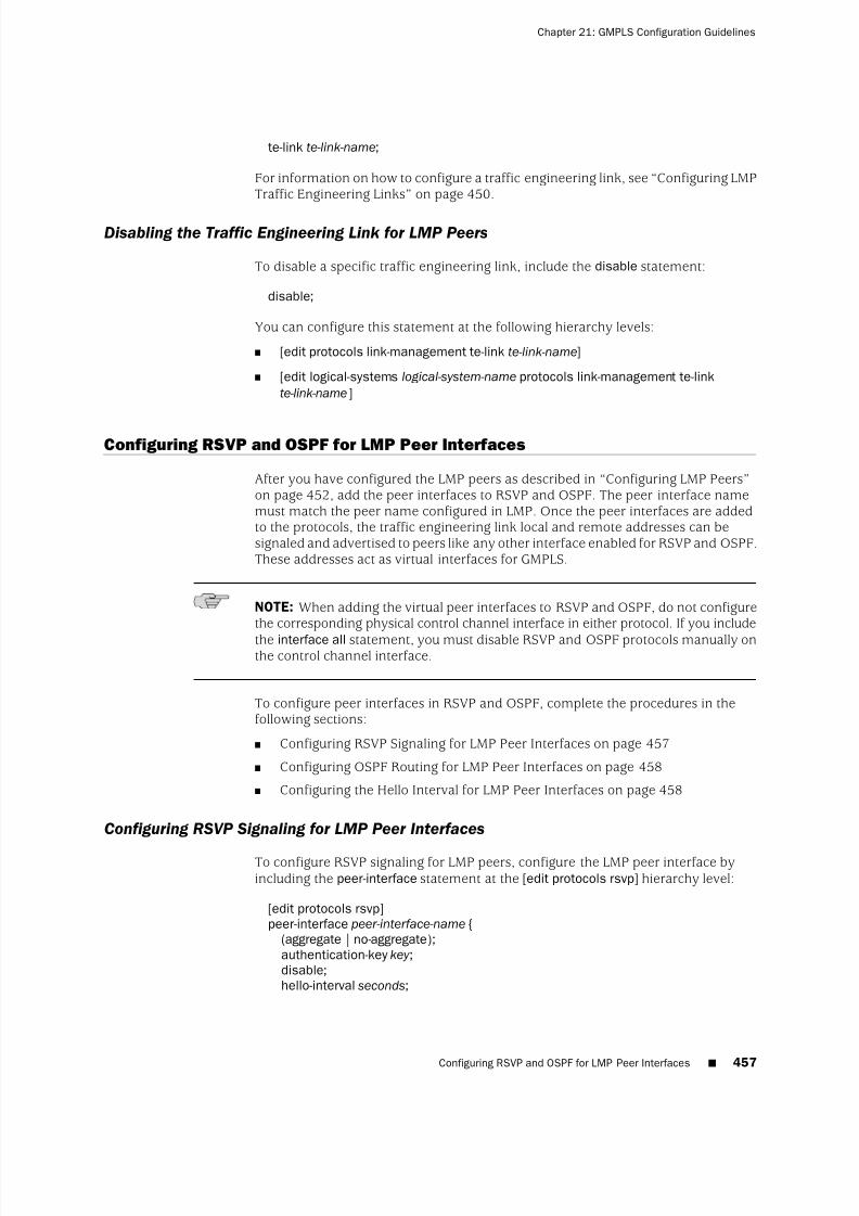
8/7/2019 Config Guide Mpls Applications
http://slidepdf.com/reader/full/config-guide-mpls-applications 495/547
te-link te-link-name;
For information on how to configure a traffic engineering link, see “Configuring LMPTraffic Engineering Links” on page 450.
Disabling the Traffic Engineering Link for LMP Peers
To disable a specific traffic engineering link, include the disable statement:
disable;
You can configure this statement at the following hierarchy levels:
■ [edit protocols link-management te-link te-link-name]
■ [edit logical-systems logical-system-name protocols link-management te-linkte-link-name]
Configuring RSVP and OSPF for LMP Peer Interfaces
After you have configured the LMP peers as described in “Configuring LMP Peers”on page 452, add the peer interfaces to RSVP and OSPF. The peer interface namemust match the peer name configured in LMP. Once the peer interfaces are addedto the protocols, the traffic engineering link local and remote addresses can besignaled and advertised to peers like any other interface enabled for RSVP and OSPF.These addresses act as virtual interfaces for GMPLS.
NOTE: When adding the virtual peer interfaces to RSVP and OSPF, do not configurethe corresponding physical control channel interface in either protocol. If you include
the interface all statement, you must disable RSVP and OSPF protocols manually onthe control channel interface.
To configure peer interfaces in RSVP and OSPF, complete the procedures in thefollowing sections:
■ Configuring RSVP Signaling for LMP Peer Interfaces on page 457
■ Configuring OSPF Routing for LMP Peer Interfaces on page 458
■ Configuring the Hello Interval for LMP Peer Interfaces on page 458
Configuring RSVP Signaling for LMP Peer Interfaces
To configure RSVP signaling for LMP peers, configure the LMP peer interface byincluding the peer-interface statement at the [edit protocols rsvp] hierarchy level:
[edit protocols rsvp]peer-interface peer-interface-name {
(aggregate | no-aggregate);authentication-key key ;disable;hello-interval seconds;
Configuring RSVP and OSPF for LMP Peer Interfaces ■ 457
Chapter 21: GMPLS Configuration Guidelines

8/7/2019 Config Guide Mpls Applications
http://slidepdf.com/reader/full/config-guide-mpls-applications 496/547
(reliable | no-reliable);}
The statements configured at the [edit protocols rsvp peer-interface peer-interface-name]
hierarchy level have the same functionality as the statements configured at the [editprotocols rsvp interface interface-name] hierarchy level.
Configuring OSPF Routing for LMP Peer Interfaces
To configure OSPF routing for LMP peers, configure the name of the LMP peer byincluding the peer-interface statement at the [edit protocols ospf area area-number ]hierarchy level:
[edit protocols ospf area area-number ]peer-interface peer-interface-name {
dead-interval seconds;disable;
hello-interval seconds;retransmit-interval seconds;transit-delay seconds;
}
For information on how to configure OSPF statements, see the JUNOS Routing Protocols Configuration Guide.
Configuring the Hello Interval for LMP Peer Interfaces
Hello packets are used to indicate to neighboring routers that the peer interface isstill up and running. The hello interval must be the same for all routers on a sharedlogical IP network. You can specify a hello interval from 1 through 255 seconds. The
default hello interval is normally 10 seconds. For nonbroadcast networks, the defaulthello interval is 120 seconds.
To specify how often the router sends hello packets out the peer interface, configurethe hello-interval statement:
hello-interval seconds;
You can configure this statement at the following hierarchy levels:
■ [edit protocols ospf area area-number peer-interface peer-interface-name]
■ [edit logical-systems logical-system-name protocols ospf area area-number
peer-interface peer-interface-name]
Configuring MPLS Paths for GMPLS
As part of the configuration for GMPLS, you need to establish an MPLS path for eachunique device connected through GMPLS. Configure the traffic engineering linkremote address as the address at the [edit protocols mpls path path-name] hierarchylevel. Constrained Shortest Path First (CSPF) is supported so you can choose eitherthe strict or loose option with the address.
458 ■ Configuring MPLS Paths for GMPLS
JUNOS 9.6 MPLS Applications Configuration Guide

8/7/2019 Config Guide Mpls Applications
http://slidepdf.com/reader/full/config-guide-mpls-applications 497/547
See “LMP Configuration Overview” on page 449 for information about how to obtaina traffic engineering link remote address.
To configure the MPLS path, include the path statement at the [edit protocols mpls]
hierarchy level:
[edit protocols mpls]path path-name {
next-hop-address (strict | loose);}
For information about how to configure MPLS paths, see “Creating Named Paths”on page 52.
Tracing LMP Traffic
To trace LMP protocol traffic, include the traceoptions statement at the [edit protocols
link-management] hierarchy level:
[edit protocols link-management]traceoptions {
file filename <files number > <size size> <world-readable | no-world-readable>;flag flag <flag-modifier > <disable>;
}
Use the file statement to specify the name of the file that receives the output of thetracing operation. All files are placed in the directory /var/log.
The following trace flags display the operations associated with the sending andreceiving of various LMP messages:
■ all—Trace all available operations■ hello-packets—Trace hello packets on any LMP control channel
■ init—Output from the initialization messages
■ packets—Trace all packets other than hello packets on any LMP control channel
■ parse—Operation of the parser
■ process—Operation of the general configuration
■ route-socket—Operation of route socket events
■ routing—Operation of the routing protocols
■ server—Server processing operations
■ show—Servicing operations for show commands
■ state—Trace state transitions of the LMP control channels and traffic engineeringlinks
Each flag can carry one or more of the following flag modifiers:
■ detail—Provide detailed trace information
■ receive—Packets being received
Tracing LMP Traffic ■ 459
Chapter 21: GMPLS Configuration Guidelines

8/7/2019 Config Guide Mpls Applications
http://slidepdf.com/reader/full/config-guide-mpls-applications 498/547
■ send—Packets being transmitted
Configuring MPLS LSPs for GMPLS
To enable the proper GMPLS switching parameters, configure the label-switched path(LSP) attributes that are appropriate for your network connection. The default valuefor switching-type is psc-1, which is also appropriate for standard MPLS.
To configure the LSP attributes, include the lsp-attributes statement at the [editprotocols mpls label-switched-path lsp-name] hierarchy level:
[edit protocols mpls label-switched-path lsp-name]lsp-attributes {
encoding-type type;gpid gpid;signal-bandwidth type;
switching-type type;}
If you include the no-cspf statement in the label-switched path configuration, youmust also configure primary and secondary paths, or the configuration cannot becommitted.
The following sections describe how to configure each of the LSP attributes for aGMPLS LSP:
■ Configuring the Encoding Type on page 460
■ Configuring the GPID on page 461
■ Configuring the Signal Bandwidth Type on page 461
■ Configuring GMPLS Bidirectional LSPs on page 461■ Allowing Non-Packet GMPLS LSPs to Establish Paths Through Routers Running
the JUNOS Software on page 462
Configuring the Encoding Type
You need to specify the encoding type of the payload carried by the LSP. It can beany of the following:
■ ethernet—Ethernet
■ packet—Packet
■ pdh—Plesiochronous digital hierarchy (PDH)
■ sonet-sdh—SONET/SDH
The default value is packet.
To configure the encoding type, include the encoding-type statement at the [editprotocols mpls label-switched-path lsp-name lsp-attributes] hierarchy level:
[edit protocols mpls label-switched-path lsp-name lsp-attributes]
460 ■ Configuring MPLS LSPs for GMPLS
JUNOS 9.6 MPLS Applications Configuration Guide

8/7/2019 Config Guide Mpls Applications
http://slidepdf.com/reader/full/config-guide-mpls-applications 499/547
encoding-type type;
Configuring the GPID
You need to specify the type of payload carried by the LSP. The payload is the typeof packet underneath the MPLS label. The payload is specified by the generalizedpayload identifier (GPID).
You can specify the GPID with any of the following values:
■ hdlc—High-Level Data Link Control (HDLC)
■ ethernet—Ethernet
■ ipv4—IP version 4 (default)
■ pos-scrambling-crc-16—For interoperability with other vendors’ equipment
■ pos-no-scrambling-crc-16—For interoperability with other vendors’ equipment
■ pos-scrambling-crc-32—For interoperability with other vendors’ equipment
■ pos-no-scrambling-crc-32—For interoperability with other vendors’ equipment
■ ppp—Point-to-Point Protocol (PPP)
To configure the GPID, include the gpid statement at the [edit protocols mplslabel-switched-path lsp-name lsp-attributes] hierarchy level:
[edit protocols mpls label-switched-path lsp-name lsp-attributes]gpid gpid;
Configuring the Signal Bandwidth Type
The signal bandwidth type is the encoding used for path computation and admissioncontrol. To configure the signal bandwidth type, include the signal-bandwidthstatementat the [edit protocols mpls label-switched-path lsp-name lsp-attributes] hierarchy level:
[edit protocols mpls label-switched-path lsp-name lsp-attributes]signal-bandwidth type;
Configuring GMPLS Bidirectional LSPs
Because MPLS and GMPLS use the same configuration hierarchy for LSPs, it is helpfulto know which LSP attributes control LSP functionality. Standard MPLSpacket-switched LSPs are unidirectional, whereas GMPLS nonpacket LSPs are
bidirectional.
If you use the default packet-switching type of psc-1, your LSP becomes unidirectional.To enable a GMPLS bidirectional LSP, you must select a non-packet-switching typeoption, such as lambda, fiber, or ethernet. Include the switching-type statement at the[edit protocols mpls label-switched-path lsp-name lsp-attributes] hierarchy level:
[edit protocols mpls label-switched-path lsp-name lsp-attributes]switching-type (lambda | fiber | ethernet);
Configuring MPLS LSPs for GMPLS ■ 461
Chapter 21: GMPLS Configuration Guidelines

8/7/2019 Config Guide Mpls Applications
http://slidepdf.com/reader/full/config-guide-mpls-applications 500/547
Allowing Non-Packet GMPLS LSPs to Establish Paths Through Routers Running the JUNOS
Software
By setting the A-bit in the Admin Status object. you can enable nonpacket GMPLSLSPs to establish paths through routers that run the JUNOS Software. When an ingressrouter sends an RSVP PATH message with the Admin Status A-bit set, an externaldevice (not a router running the JUNOS Software) can either perform a Layer 1 pathsetup test or help bring up an optical cross-connect.
When set, the A-bit in the Admin Status object indicates the administrative downstatus for an LSP. This feature is used specifically by nonpacket GMPLS LSPs. It doesnot affect control path setup or data forwarding for packet LSPs.
The JUNOS Software does not distinguish between the control path setup and datapath setup. Other nodes along the network path use RSVP PATH signaling using theA-bit in a meaningful way.
To configure the Admin Status object for a GMPLS LSP, include the admin-downstatement:
admin-down;
You can include this statement at the following hierarchy levels:
■ [edit protocols mpls label-switched-path lsp-name]
■ [edit logical-systems logical-system-nameprotocols mpls label-switched-path lsp-name]
Gracefully Tearing Down GMPLS LSPs
You can gracefully tear down nonpacket GMPLS LSPs. An LSP that is torn downabruptly, a common process in a packet-switched network, can cause stabilityproblems in nonpacket-switched networks. To maintain the stability of nonpacket-switched networks, it might be necessary to tear down LSPs gracefully.
The following sections describe how to tear down GMPLS LSPs gracefully:
■ Temporarily Deleting GMPLS LSPs on page 462
■ Permanently Deleting GMPLS LSPs on page 463
■ Configuring the Graceful Deletion Timeout Interval on page 463
Temporarily Deleting GMPLS LSPs
You can gracefully tear down a GMPLS LSP using the clear rsvp session gracefullycommand.
This command gracefully tears down an RSVP session for a nonpacket LSP in twopasses. In the first pass, the Admin Status object is signaled along the path to theendpoint of the LSP. During the second pass, the LSP is taken down. Using thiscommand, the LSP is taken down temporarily. After the appropriate interval, theGMPLS LSP is resignaled and then reestablished.
462 ■ Gracefully Tearing Down GMPLS LSPs
JUNOS 9.6 MPLS Applications Configuration Guide

8/7/2019 Config Guide Mpls Applications
http://slidepdf.com/reader/full/config-guide-mpls-applications 501/547
The clear rsvp session gracefully command has the following properties:
■ It only works on the ingress and egress routers of an RSVP session. If used on atransit router, it has the same behavior as the clear rsvp session command.
■ It only works for nonpacket LSPs. If used with packet LSPs, it has the samebehavior as the clear rsvp session command.
For more information, see the JUNOS Routing Protocols and Policies Command Reference.
Permanently Deleting GMPLS LSPs
When you disable an LSP in the configuration, the LSP is permanently deleted. Byconfiguring the disable statement, you can disable a GMPLS LSP permanently. If theLSP being disabled is a nonpacket LSP, then the graceful LSP tear-down proceduresthat use the Admin Status object are used. If the LSP being disabled is a packet LSP,
then the regular signaling procedures for LSP deletion are used.
To disable a GMPLS LSP, include the disable statement at any of the followinghierarchy levels:
■ [edit protocols mpls label-switched-path lsp-name]—Disables the LSP.
■ [edit protocols link-management te-link te-link-name]—Disables a traffic engineeringlink.
■ [edit protocols link-management te-link te-link-name
interface interface-name]—Disables an interface used by a traffic engineering link.
Configuring the Graceful Deletion Timeout Interval
The router that initiates the graceful deletion procedure for an RSVP session waitsfor the graceful deletion timeout interval to ensure that all routers along the path(especially the ingress and egress routers) have prepared for the LSP to be takendown.
The ingress router initiates the graceful deletion procedure by sending the AdminStatus object in the path message with the D bit set. The ingress router expects toreceive an Resv message with the D bit set from the egress router. If the ingressrouter does not receive this message within the time specified by the graceful deletiontimeout interval, it initiates a forced tear-down of the LSP by sending a PathTearmessage.
To configure the graceful deletion timeout interval, include the graceful-deletion-timeoutstatement at the [edit protocols rsvp] hierarchy level. You can configure a time frombetween 1 through 300 seconds. The default value is 30 seconds.
graceful-deletion-timeout seconds;
You can configure this statement at the following hierarchy levels:
■ [edit protocols rsvp]
■ [edit logical-systems logical-system-name protocols rsvp]
Gracefully Tearing Down GMPLS LSPs ■ 463
Chapter 21: GMPLS Configuration Guidelines

8/7/2019 Config Guide Mpls Applications
http://slidepdf.com/reader/full/config-guide-mpls-applications 502/547
You can use the show rsvp version command to determine the current value configuredfor the graceful deletion timeout.
464 ■ Gracefully Tearing Down GMPLS LSPs
JUNOS 9.6 MPLS Applications Configuration Guide
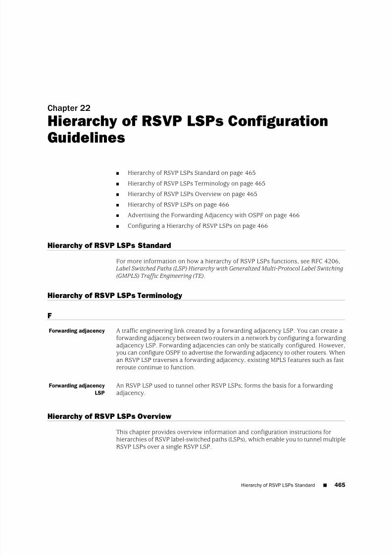
8/7/2019 Config Guide Mpls Applications
http://slidepdf.com/reader/full/config-guide-mpls-applications 503/547
Chapter 22
Hierarchy of RSVP LSPs ConfigurationGuidelines
■ Hierarchy of RSVP LSPs Standard on page 465
■ Hierarchy of RSVP LSPs Terminology on page 465
■ Hierarchy of RSVP LSPs Overview on page 465■ Hierarchy of RSVP LSPs on page 466
■ Advertising the Forwarding Adjacency with OSPF on page 466
■ Configuring a Hierarchy of RSVP LSPs on page 466
Hierarchy of RSVP LSPs Standard
For more information on how a hierarchy of RSVP LSPs functions, see RFC 4206, Label Switched Paths (LSP) Hierarchy with Generalized Multi-Protocol Label Switching(GMPLS) Traffic Engineering (TE).
Hierarchy of RSVP LSPs Terminology
F
Forwarding adjacency A traffic engineering link created by a forwarding adjacency LSP. You can create aforwarding adjacency between two routers in a network by configuring a forwardingadjacency LSP. Forwarding adjacencies can only be statically configured. However,you can configure OSPF to advertise the forwarding adjacency to other routers. Whenan RSVP LSP traverses a forwarding adjacency, existing MPLS features such as fastreroute continue to function.
Forwarding adjacency
LSP An RSVP LSP used to tunnel other RSVP LSPs; forms the basis for a forwardingadjacency.
Hierarchy of RSVP LSPs Overview
This chapter provides overview information and configuration instructions forhierarchies of RSVP label-switched paths (LSPs), which enable you to tunnel multipleRSVP LSPs over a single RSVP LSP.
Hierarchy of RSVP LSPs Standard ■ 465

8/7/2019 Config Guide Mpls Applications
http://slidepdf.com/reader/full/config-guide-mpls-applications 504/547
The following sections provide an overview of how a hierarchy of RSVP LSPs functions:
■ Hierarchy of RSVP LSPs on page 466
■ Advertising the Forwarding Adjacency with OSPF on page 466
Hierarchy of RSVP LSPs
Forwarding adjacencies are configured and managed as point-to-point trafficengineering links by including statements at the [edit protocols link-management]hierarchy level. For the forwarding adjacency to function properly, you also need tomake RSVP aware of the forwarding adjacency by configuring the correspondingpeer interface at the [edit protocols rsvp] hierarchy level.
Although forwarding adjacency LSPs are configured and managed as trafficengineering links on the local router, it is not necessary to advertise these trafficengineering links to other routers in the network. However, if you want to
automatically forward MPLS traffic over the forwarding adjacency or want otherrouters to compute paths over the forwarding adjacency, you must configure OSPFto advertise the forwarding adjacency to the other routers in the network and addthe forwarding adjacency to the traffic engineering database. OSPF is the onlysupported interior gateway protocol (IGP).
Advertising the Forwarding Adjacency with OSPF
Once a forwarding adjacency LSP and the corresponding traffic engineering link youhave configured, you can configure OSPF to advertise the forwarding adjacency.Unlike regular traffic engineering links, OSPF hellos are not exchanged between theforwarding adjacency LSP endpoints and therefore no routing adjacency is created
between the forwarding adjacency endpoints. If you issue a show ospf neighborcommand on an ingress forwarding adjacency, the command displays the egressrouter of the forwarding adjacency LSP as a neighbor. However, no real OSPFadjacency is established (no OSPF hellos are exchanged) between the ingress andegress routers. For display purposes only, OSPF creates a pseudo-neighborcorresponding to the peer.
You can configure forwarding adjacencies over existing MPLS networks. A forwardingadjacency LSP is signaled as a regular MPLS LSP without generalized MPLS (GMPLS)extensions. When the forwarding adjacency LSP is advertised as a traffic engineeringlink in OSPF, the corresponding traffic engineering link in OSPF is also advertisedas a regular MPLS traffic engineering link without GMPLS extensions.
Configuring a Hierarchy of RSVP LSPs
The following sections describe how to configure a hierarchy of RSVP LSPs:
■ Configuring an RSVP LSP on Ingress Routers on page 467
■ Configuring Forwarding Adjacencies on page 467
■ Configuring RSVP for Forwarding Adjacencies on page 468
■ Advertising Forwarding Adjacencies Using OSPF on page 469
466 ■ Hierarchy of RSVP LSPs
JUNOS 9.6 MPLS Applications Configuration Guide
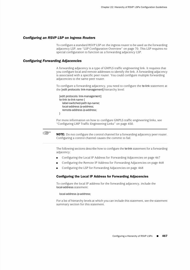
8/7/2019 Config Guide Mpls Applications
http://slidepdf.com/reader/full/config-guide-mpls-applications 505/547
Configuring an RSVP LSP on Ingress Routers
To configure a standard RSVP LSP on the ingress router to be used as the forwardingadjacency LSP, see “LSP Configuration Overview” on page 70. This LSP requires nospecial configuration to function as a forwarding adjacency LSP.
Configuring Forwarding Adjacencies
A forwarding adjacency is a type of GMPLS traffic engineering link. It requires thatyou configure local and remote addresses to identify the link. A forwarding adjacencyis associated with a specific peer router. You could configure multiple forwardingadjacencies to the same peer router.
To configure a forwarding adjacency, you need to configure the te-link statement atthe [edit protocols link-management] hierarchy level:
[edit protocols link-management]te-link te-link-name {
label-switched-path lsp-name;local-address ip-address;remote-address ip-address;
}
For more information on how to configure GMPLS traffic engineering links, see“Configuring LMP Traffic Engineering Links” on page 450.
NOTE: Do not configure the control channel for a forwarding adjacency peer router.Configuring a control channel causes the commit to fail.
The following sections describe how to configure the te-link statement for a forwardingadjacency:
■ Configuring the Local IP Address for Forwarding Adjacencies on page 467
■ Configuring the Remote IP Address for Forwarding Adjacencies on page 468
■ Configuring the LSP for Forwarding Adjacencies on page 468
Configuring the Local IP Address for Forwarding Adjacencies
To configure the local IP address for the forwarding adjacency, include thelocal-address statement:
local-address ip-address;
For a list of hierarchy levels at which you can include this statement, see the statementsummary section for this statement.
Configuring a Hierarchy of RSVP LSPs ■ 467
Chapter 22: Hierarchy of RSVP LSPs Configuration Guidelines

8/7/2019 Config Guide Mpls Applications
http://slidepdf.com/reader/full/config-guide-mpls-applications 506/547
Configuring the Remote IP Address for Forwarding Adjacencies
The address of the peer router is the node ID for the forwarding adjacency LSP egressnode. You configure this node ID for the forwarding adjacency using theremote-address statement:
remote-address ip-address;
You can include this statement at the following hierarchy levels:
■ [edit protocols link-management te-link te-link-name],
■ [edit logical-systems logical-system-name protocols link-management te-linkte-link-name]
Configuring the LSP for Forwarding Adjacencies
To configure a router to function as a forwarding adjacency, the label-switched-pathstatement and specify the LSP configured in “Configuring an RSVP LSP on IngressRouters” on page 467:
label-switched-path label-switched-path-name;
You can include this statement at the following hierarchy levels:
■ [edit protocols link-management te-link te-link-name]
■ [edit logical-systems logical-system-name protocols link-management te-linkte-link-name]
Configuring RSVP for Forwarding Adjacencies
For the forwarding adjacency to function properly, RSVP must be made aware of it.Do this by specifying the name of the peer interface corresponding to thelink-management peer associated with the forwarding adjacency. Including thepeer-interface statement at the [edit protocols rsvp] hierarchy level enables RSVP touse all of the traffic engineering links configured for that peer. You can also configureRSVP control-plane parameters such as the hello interval and refresh reduction.
To configure RSVP to recognize a forwarding adjacency, include the peer-interfacestatement:
peer-interface peer-interface-name {
disable;(aggregate | no-aggregate);authentication-key key ;hello-interval seconds;(reliable | no-reliable);
}
You can include this statement at the following hierarchy levels:
■ [edit protocols rsvp]
468 ■ Configuring a Hierarchy of RSVP LSPs
JUNOS 9.6 MPLS Applications Configuration Guide

8/7/2019 Config Guide Mpls Applications
http://slidepdf.com/reader/full/config-guide-mpls-applications 507/547

8/7/2019 Config Guide Mpls Applications
http://slidepdf.com/reader/full/config-guide-mpls-applications 508/547
470 ■ Configuring a Hierarchy of RSVP LSPs
JUNOS 9.6 MPLS Applications Configuration Guide

8/7/2019 Config Guide Mpls Applications
http://slidepdf.com/reader/full/config-guide-mpls-applications 509/547
Chapter 23
Summary of GMPLS ConfigurationStatements
This chapter provides a reference for each Generalized MPLS (GMPLS) configurationstatement. The statements are organized alphabetically.
address
Syntax address ip-address;
Hierarchy Level [edit logical-systems logical-system-name protocols link-management peer peer-name],[edit protocols link-management peer peer-name]
Release Information Statement introduced before JUNOS Release 7.4.
Description Specify the ID of the peer.
Default The loopback address is advertised.
Options ip-address—IP address of the peer.
Usage Guidelines See “Configuring the ID for LMP Peers” on page 453.
Required Privilege Level routing—To view this statement in the configuration.routing-control—To add this statement to the configuration.
admin-down
See admin-down
address ■ 471

8/7/2019 Config Guide Mpls Applications
http://slidepdf.com/reader/full/config-guide-mpls-applications 510/547
control-channel
Syntax control-channel control-channel-interface;
Hierarchy Level [edit logical-systems logical-system-name protocols link-management peer peer-name],[edit protocols link-management peer peer-name]
Release Information Statement introduced before JUNOS Release 7.4.
Description Specify the control channel interface for the peer.
Options control-channel-interface—Name of the control channel interface.
Usage Guidelines See “Configuring LMP Peers” on page 452.
Required Privilege Level routing—To view this statement in the configuration.routing-control—To add this statement to the configuration.
dead-interval
Syntax dead-interval seconds;
Hierarchy Level [edit logical-systems logical-system-name protocols ospf area area-number
peer-interface peer-interface-name],[edit protocols ospf area area-number peer-interface peer-interface-name]
Release Information Statement introduced before JUNOS Release 7.4.Description Specify how long OSPF and OSPF version 3 (OSPFv3) wait before declaring that a
neighboring router is unavailable. This is an interval during which the router receivesno hello packets from the neighbor.
Options seconds—Interval to wait.Range: 1 through 65,535Default: 40 seconds (four times the hello interval)
Usage Guidelines See “Configuring RSVP and OSPF for LMP Peer Interfaces” on page 457.
Required Privilege Level routing—To view this statement in the configuration.routing-control—To add this statement to the configuration.
Related Topics hello-interval
472 ■ control-channel
JUNOS 9.6 MPLS Applications Configuration Guide

8/7/2019 Config Guide Mpls Applications
http://slidepdf.com/reader/full/config-guide-mpls-applications 511/547
disable
See the following sections:
■ disable (GMPLS) on page 473
■ disable (OSPF Peer Interface) on page 473
disable (GMPLS)
Syntax disable;
Hierarchy Level [edit logical-systems logical-system-name protocols link-management te-link te-link-name],[edit protocols link-management te-link te-link-name]
Release Information Statement introduced before JUNOS Release 7.4.Description Disable a traffic engineering link.
Default The configured object is enabled (operational) unless explicitly disabled.
Usage Guidelines See “Disabling the Traffic Engineering Link for LMP Peers” on page 457.
Required Privilege Level routing—To view this statement in the configuration.routing-control—To add this statement to the configuration.
disable (OSPF Peer Interface)
Syntax disable;
Hierarchy Level [edit logical-systems logical-system-name protocols ospf area area-number
peer-interface peer-interface-name],[edit protocols ospf area area-number peer-interface peer-interface-name]
Release Information Statement introduced before JUNOS Release 7.4.
Description Disable an OSPF peer interface.
Default The configured object is enabled (operational) unless explicitly disabled.
Usage Guidelines See “Configuring RSVP and OSPF for LMP Peer Interfaces” on page 457.
Required Privilege Level routing—To view this statement in the configuration.
routing-control—To add this statement to the configuration.
disable (GMPLS) ■ 473
Chapter 23: Summary of GMPLS Configuration Statements

8/7/2019 Config Guide Mpls Applications
http://slidepdf.com/reader/full/config-guide-mpls-applications 512/547
hello-dead-interval
Syntax hello-dead-interval milliseconds;
Hierarchy Level [edit logical-systems logical-system-name protocols link-management peer peer-name
lmp-protocol],[edit protocols link-management peer peer-name lmp-protocol]
Release Information Statement introduced in JUNOS Release 8.0.
Description Specify how long the Link Management Protocol (LMP) waits before declaring thecontrol channel to be dead. This is an interval during which the router receives noLMP hello packets from the neighbor on a control that is active or up.
Options milliseconds—Interval to wait before declaring the control channel to be dead.
Range: 500 through 300,000Default: 500 milliseconds (three times the hello interval)
Usage Guidelines See “Configuring Hello Message Intervals for LMP Control Channels” on page 455.
Required Privilege Level routing—To view this statement in the configuration.routing-control—To add this statement to the configuration.
Related Topics hello-interval
474 ■ hello-dead-interval
JUNOS 9.6 MPLS Applications Configuration Guide

8/7/2019 Config Guide Mpls Applications
http://slidepdf.com/reader/full/config-guide-mpls-applications 513/547
hello-interval
See the following sections:
■ hello-interval (LMP) on page 475
■ hello-interval (OSPF) on page 475
hello-interval (LMP)
Syntax hello-interval milliseconds;
Hierarchy Level [edit logical-systems logical-system-name protocols link-management peer peer-name
lmp-protocol],[edit protocols link-management peer peer-name lmp-protocol]
Release Information Statement introduced in JUNOS Release 8.1.
Description Specify how often the router sends Link Management Protocol (LMP) hello packets.
Options milliseconds—Length of time between hello packets.Range: 150 through 300,000Default: 150 milliseconds
Usage Guidelines See “Configuring Hello Message Intervals for LMP Control Channels” on page 455.
Required Privilege Level routing—To view this statement in the configuration.routing-control—To add this statement to the configuration.
Related Topics hello-dead-interval
hello-interval (OSPF)
Syntax hello-interval seconds;
Hierarchy Level [edit logical-systems logical-system-name protocols ospf area area-number
peer-interface peer-interface-name],[edit protocols ospf area area-number peer-interface peer-interface-name]
Release Information Statement introduced before JUNOS Release 7.4.
Description Specify how often the router sends hello packets out the peer interface. The hellointerval must be the same for all routers on a shared logical IP network.
Options seconds—Length of time between hello packets.Range: 1 through 255Default: 10 seconds; 120 seconds (nonbroadcast networks)
Usage Guidelines See “Configuring RSVP and OSPF for LMP Peer Interfaces” on page 457.
Required Privilege Level routing—To view this statement in the configuration.routing-control—To add this statement to the configuration.
Related Topics dead-interval.
hello-interval (LMP) ■ 475
Chapter 23: Summary of GMPLS Configuration Statements

8/7/2019 Config Guide Mpls Applications
http://slidepdf.com/reader/full/config-guide-mpls-applications 514/547
interface
Syntax interface interface-name;
Hierarchy Level [edit logical-systems logical-system-name protocols link-management te-link te-link-name],[edit protocols link-management te-link te-link-name]
Release Information Statement introduced before JUNOS Release 7.4.
Description Specify the egress router interface.
Options interface-name—Name of the interface to the egress router.
Usage Guidelines See “LMP Configuration Overview” on page 449.
Required Privilege Level routing—To view this statement in the configuration.routing-control—To add this statement to the configuration.
label-switched-path
Syntax label-switched-path lsp-name;
Hierarchy Level [edit logical-systems logical-system-name protocols link-management te-link te-link-name],[edit protocols link-management te-link te-link-name]
Release Information Statement introduced in JUNOS Release 7.4.
Description Specify the label-switched path (LSP) to be used by the forwarding adjacency.
Options lsp-name—Name of the LSP.
Usage Guidelines See “Configuring Forwarding Adjacencies” on page 467.
Required Privilege Level routing—To view this statement in the configuration.routing-control—To add this statement to the configuration.
476 ■ interface
JUNOS 9.6 MPLS Applications Configuration Guide

8/7/2019 Config Guide Mpls Applications
http://slidepdf.com/reader/full/config-guide-mpls-applications 515/547
link-management
Syntax link-management { ... }
Hierarchy Level [edit logical-systems logical-system-name protocols],[edit protocols]
Release Information Statement introduced before JUNOS Release 7.4.
Description Enable Link Management Protocol (LMP) on the router.
Usage Guidelines See “LMP Configuration Overview” on page 449.
Required Privilege Level routing—To view this statement in the configuration.routing-control—To add this statement to the configuration.
lmp-control-channel
Syntax lmp-control-channel control-channel-interface {remote-address ip-address;
}
Hierarchy Level [edit logical-systems logical-system-name protocols link-management peer peer-name],[edit protocols link-management peer peer-name]
Release Information Statement introduced in JUNOS Release 8.1.
Description Specify the Link Management Protocol (LMP) control channel interface for the peer.
Options control-channel-interface—Name of the control channel interface.
The remaining statement is described separately in this chapter.
Usage Guidelines See “Configuring the LMP Control Channel Interface for the Peer” on page 454.
Required Privilege Level routing—To view this statement in the configuration.routing-control—To add this statement to the configuration.
link-management ■ 477
Chapter 23: Summary of GMPLS Configuration Statements

8/7/2019 Config Guide Mpls Applications
http://slidepdf.com/reader/full/config-guide-mpls-applications 516/547
lmp-protocol
Syntax lmp-protocol {hello-interval milliseconds;hello-dead-interval milliseconds;passive;retransmission-interval milliseconds;retry-limit number ;
}
Hierarchy Level [edit logical-systems logical-system-name protocols link-management peer peer-name],[edit protocols link-management peer peer-name]
Release Information Statement introduced in JUNOS Release 8.1.
Description Configure attributes of Link Management Protocol (LMP) to establish and maintainthe LMP control channel for the peer.
Options The statements are described separately in this chapter.
Usage Guidelines See “Configuring LMP Peers” on page 452.
Required Privilege Level routing—To view this statement in the configuration.routing-control—To add this statement to the configuration.
local-address
Syntax local-address ip-address;
Hierarchy Level [edit logical-systems logical-system-name protocols link-management te-link te-link-name],[edit logical-systems logical-system-nameprotocols link-management te-link te-link-name
interface interface-name],[edit protocols link-management te-link te-link-name],[edit protocols link-management te-link te-link-name interface interface-name]
Release Information Statement introduced before JUNOS Release 7.4.
Description Specify the local IP address associated with the traffic engineering link.
Options local-address—Local IP address of the traffic engineering link.
Usage Guidelines See “Configuring the Local IP Address for Traffic Engineering Links” on page 451 and“Configuring the Local IP Address for Forwarding Adjacencies” on page 467.
Required Privilege Level routing—To view this statement in the configuration.routing-control—To add this statement to the configuration.
478 ■ lmp-protocol
JUNOS 9.6 MPLS Applications Configuration Guide

8/7/2019 Config Guide Mpls Applications
http://slidepdf.com/reader/full/config-guide-mpls-applications 517/547
passive
Syntax passive;
Hierarchy Level [edit logical-systems logical-system-name protocols link-management peer peer-name
lmp-protocol],[edit protocols link-management peer peer-name lmp-protocol]
Release Information Statement introduced in JUNOS Release 8.1.
Description Specify the router to not configure the Link Management Protocol (LMP) controlchannels, but to wait for the remote peer to configure the LMP control channels.
Usage Guidelines See “Preventing the Local Peer from Initiating LMP Negotiation” on page 456.
Required Privilege Level routing—To view this statement in the configuration.routing-control—To add this statement to the configuration.
peer
Syntax peer peer-name {address ip-address;control-channel control-channel-interface;lmp-control-channel control-channel-interface;lmp-protocol {
hello-interval milliseconds;hello-dead-interval milliseconds;
passive;retransmission-interval milliseconds;retry-limit number ;
}te-link te-link-name;
}
Hierarchy Level [edit logical-systems logical-system-name protocols link-management],[edit protocols link-management]
Release Information Statement introduced before JUNOS 7.4. For JUNOS 8.1, the lmp-protocol statementand sub-statements were added.
Description Configure a network peer.
Options peer-name—Name of the network peer.
The remaining statements are described separately in this chapter.
Usage Guidelines See “Configuring LMP Peers” on page 452.
Required Privilege Level routing—To view this statement in the configuration.routing-control—To add this statement to the configuration.
passive ■ 479
Chapter 23: Summary of GMPLS Configuration Statements

8/7/2019 Config Guide Mpls Applications
http://slidepdf.com/reader/full/config-guide-mpls-applications 518/547
peer-interface
See the following sections:
■ peer-interface (OSPF) on page 480
■ peer-interface (for RSVP) on page 480
peer-interface (OSPF)
Syntax peer-interface peer-interface-name {dead-interval seconds;disable;hello-interval seconds;retransmit-interval seconds;transit-delay seconds;
}
Hierarchy Level [edit logical-systems logical-system-name protocols ospf area area-id],[edit protocols ospf area area-id]
Release Information Statement introduced before JUNOS Release 7.4.
Description Configure the control channel. The peer interface name is the same as the peerinterface name configured under LMP.
Options The options are explained separately.
Usage Guidelines See “Configuring RSVP and OSPF for LMP Peer Interfaces” on page 457 and“
Advertising Forwarding Adjacencies Using OSPF”
on page 469.Required Privilege Level routing—To view this statement in the configuration.
routing-control—To add this statement to the configuration.
Related Topics JUNOS Routing Protocols Configuration Guide
peer-interface (for RSVP)
See peer-interface
480 ■ peer-interface (OSPF)
JUNOS 9.6 MPLS Applications Configuration Guide

8/7/2019 Config Guide Mpls Applications
http://slidepdf.com/reader/full/config-guide-mpls-applications 519/547
remote-address
See the following sections:
■ remote-address (for LMP Control Channel) on page 481
■ remote-address (for LMP Traffic Engineering) on page 481
remote-address (for LMP Control Channel)
Syntax remote-address ip-address;
Hierarchy Level [edit logical-systems logical-system-name protocols link-management peer peer-name
lmp-control-channel control-channel-interface],[edit protocols link-management peer peer-name lmp-control-channel
control-channel-interface]
Release Information Statement introduced in JUNOS Release 8.1.
Description Specify the remote IP address for the Link Management Protocol (LMP) controlchannel interface.
Options ip-address—Remote IP address mapped to the LMP control channel interface.
Usage Guidelines See “Configuring the Remote IP Address for LMP Control Channels” on page 454.
Required Privilege Level routing—To view this statement in the configuration.routing-control—To add this statement to the configuration.
remote-address (for LMP Traffic Engineering)
Syntax remote-address ip-address;
Hierarchy Level [edit logical-systems logical-system-name protocols link-management te-link te-link-name],[edit logical-systems logical-system-nameprotocols link-management te-link te-link-name
interface interface-name],[edit protocols link-management te-link te-link-name],[edit protocols link-management te-link te-link-name interface interface-name]
Release Information Statement introduced before JUNOS Release 7.4.
Description Specify the remote IP address for the traffic engineering link.
Options ip-address—Remote IP address mapped to the traffic engineering link.
Usage Guidelines See “Configuring the Remote IP Address for Traffic Engineering Links” on page 451and “Configuring the Remote IP Address for Forwarding Adjacencies” on page 468.
Required Privilege Level routing—To view this statement in the configuration.routing-control—To add this statement to the configuration.
remote-address (for LMP Control Channel) ■ 481
Chapter 23: Summary of GMPLS Configuration Statements

8/7/2019 Config Guide Mpls Applications
http://slidepdf.com/reader/full/config-guide-mpls-applications 520/547
remote-id
Syntax remote-id id-number ;
Hierarchy Level [edit logical-systems logical-system-name protocols link-management te-link te-link-name],[edit logical-systems logical-system-nameprotocols link-management te-link te-link-name
interface interface-name],[edit protocols link-management te-link te-link-name],[edit protocols link-management te-link te-link-name interface interface-name]
Release Information Statement introduced before JUNOS Release 7.4.
Description Specify the ID assigned to a traffic engineering link or an interface (resource) on thepeer node.
Options id-number —ID number for the remote device.
Usage Guidelines See “Configuring the Remote ID for Traffic Engineering Links” on page 452.
Required Privilege Level routing—To view this statement in the configuration.routing-control—To add this statement to the configuration.
retransmission-interval
Syntax retransmission-interval milliseconds;
Hierarchy Level [edit logical-systems logical-system-name protocols link-management peer peer-name
lmp-protocol],[edit protocols link-management peer peer-name lmp-protocol]
Release Information Statement introduced in JUNOS Release 8.1.
Description Specify how often Link Management Protocol (LMP) sends Config and LinkSummarymessages on the LMP control channel.
Options milliseconds—Length of time between Config messages.Range: 500 through 300,000Default: 500 milliseconds
Usage Guidelines See “Controlling Message Exchange for LMP Control Channels” on page 456.
Required Privilege Level routing—To view this statement in the configuration.routing-control—To add this statement to the configuration.
Related Topics retry-limit
482 ■ remote-id
JUNOS 9.6 MPLS Applications Configuration Guide

8/7/2019 Config Guide Mpls Applications
http://slidepdf.com/reader/full/config-guide-mpls-applications 521/547
retransmit-interval
Syntax retransmit-interval seconds;
Hierarchy Level [edit logical-systems logical-system-name protocols ospf area area-number
peer-interface peer-interface-name],[edit protocols ospf area area-number peer-interface peer-interface-name]
Release Information Statement introduced before JUNOS Release 7.4.
Description Specify how long the router waits to receive a link-state acknowledgment packetbefore retransmitting link-state advertisements to a peer interface’s neighbors.
Options seconds—Interval to wait for a link-state acknowledgment packet.Range: 1 through 65,535
Default: 5 secondsUsage Guidelines See “Configuring RSVP and OSPF for LMP Peer Interfaces” on page 457.
Required Privilege Level routing—To view this statement in the configuration.routing-control—To add this statement to the configuration.
retry-limit
Syntax retry-limit number ;
Hierarchy Level [edit logical-systems logical-system-name protocols link-management peer peer-name
lmp-protocol],[edit protocols link-management peer peer-name lmp-protocol]
Release Information Statement introduced in JUNOS Release 8.1.
Description Specify how many times the Link Management Protocol (LMP) sends Config andLinkSummary messages on the LMP control channel without receiving an appropriateacknowledgment before it logs a message and restarts the LMP control channelconfiguration process.
Options number —Maximum number of times messages are sent without receiving anacknowledgment.Range: 3 through 1000Default: 3
Usage Guidelines See “Controlling Message Exchange for LMP Control Channels” on page 456.
Required Privilege Level routing—To view this statement in the configuration.routing-control—To add this statement to the configuration.
Related Topics retransmission-interval
retransmit-interval ■ 483
Chapter 23: Summary of GMPLS Configuration Statements

8/7/2019 Config Guide Mpls Applications
http://slidepdf.com/reader/full/config-guide-mpls-applications 522/547
te-link
Syntax te-link te-link-name {disable;interface interface-name {
disable;local-address ip-address;remote-address ip-address;remote-id id-number ;
}local-address ip-address;remote-address ip-address;remote-id id-number ;
}
Hierarchy Level [edit logical-systems logical-system-name protocols link-management],[edit logical-systems logical-system-name protocols link-management peer peer-name],[edit protocols link-management],[edit protocols link-management peer peer-name]
Release Information Statement introduced before JUNOS Release 7.4.
Description Represent a collection of physical ports or time slots. Assign a traffic engineeringlink to the specified network peer.
Options te-link-name—Name of the collection of physical ports or the name of the time slots.
disable—Disable the traffic engineering link or an interface to a traffic engineeringlink.
The other statements are described separately in this chapter.
Usage Guidelines See “Configuring LMP Traffic Engineering Links” on page 450.
Required Privilege Level routing—To view this statement in the configuration.routing-control—To add this statement to the configuration.
484 ■ te-link
JUNOS 9.6 MPLS Applications Configuration Guide
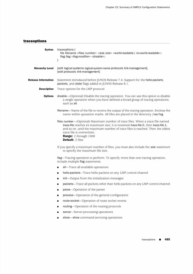
8/7/2019 Config Guide Mpls Applications
http://slidepdf.com/reader/full/config-guide-mpls-applications 523/547
traceoptions
Syntax traceoptions {file filename <files number > <size size> <world-readable | no-world-readable>;flag flag <flag-modifier > <disable>;
}
Hierarchy Level [edit logical-systems logical-system-name protocols link-management],[edit protocols link-management]
Release Information Statement introduced before JUNOS Release 7.4. Support for the hello-packets,packets, and state flags added in JUNOS Release 8.1.
Description Trace options for the LMP protocol.
Options disable—(Optional) Disable the tracing operation. You can use this option to disablea single operation when you have defined a broad group of tracing operations,such as all.
filename—Name of the file to receive the output of the tracing operation. Enclose thename within quotation marks. All files are placed in the directory /var/log.
files number —(Optional) Maximum number of trace files. When a trace file namedtrace-file reaches its maximum size, it is renamed trace-file.0, then trace-file.1,and so on, until the maximum number of trace files is reached. Then the oldesttrace file is overwritten.Range: 2 through 1000Default: 2 files
If you specify a maximum number of files, you must also include the size statementto specify the maximum file size.
flag —Tracing operation to perform. To specify more than one tracing operation,include multiple flag statements.
■ all—Trace all available operations
■ hello-packets—Trace hello packets on any LMP control channel
■ init—Output from the initialization messages
■ packets—Trace all packets other than hello packets on any LMP control channel
■ parse—Operation of the parser
■ process—Operation of the general configuration
■ route-socket—Operation of route socket events
■ routing—Operation of the routing protocols
■ server—Server processing operations
■ show—show command servicing operations
traceoptions ■ 485
Chapter 23: Summary of GMPLS Configuration Statements

8/7/2019 Config Guide Mpls Applications
http://slidepdf.com/reader/full/config-guide-mpls-applications 524/547
■ state—Trace state transitions of the LMP control channels and traffic engineeringlinks
flag-modifier —(Optional) Modifier for the tracing flag. You can specify one or moreof these modifiers:
■ detail—Provide detailed trace information
■ receive—Packets being received
■ send—Packets being transmitted
no-world-readable—(Optional) Prevents all users from reading the log file.
size size—(Optional) Maximum size of each trace file, in kilobytes (KB), megabytes(MB), or gigabytes (GB). When a trace file named trace-file reaches this size, it isrenamed trace-file.0. When the trace-file again reaches this size, trace-file.0 isrenamed trace-file.1 and trace-file is renamed trace-file.0. This renaming schemecontinues until the maximum number of trace files is reached. Then the oldesttrace file is overwritten.Syntax: xk to specify KB, xm to specify MB, or xg to specify GBRange: 10 KB through the maximum file size supported on your systemDefault: 1 MB
If you specify a maximum file size, you must also include the files statement tospecify the maximum number of files.
world-readable—(Optional) Enables log file access for all users.
Usage Guidelines See “Tracing LMP Traffic” on page 459 and the JUNOS Network Management Configuration Guide.
Required Privilege Level routing and trace—To view this statement in the configuration.routing-control and trace-control—To add this statement to the configuration.
486 ■ traceoptions
JUNOS 9.6 MPLS Applications Configuration Guide

8/7/2019 Config Guide Mpls Applications
http://slidepdf.com/reader/full/config-guide-mpls-applications 525/547
transit-delay
Syntax transit-delay seconds;
Hierarchy Level [edit logical-systems logical-system-name protocols ospf area area-number
peer-interface peer-interface-name],[edit protocols ospf area area-number peer-interface peer-interface-name]
Release Information Statement introduced before JUNOS Release 7.4.
Description Set the estimated time required to transmit a link-state update on the peer interface.When calculating this time, you should account for transmission and propagationdelays.
Options seconds—Estimated time for transmitting the link-state update.
Range: 1 through 65,535Default: 1 second
Usage Guidelines See “Configuring RSVP and OSPF for LMP Peer Interfaces” on page 457.
Required Privilege Level routing—To view this statement in the configuration.routing-control—To add this statement to the configuration.
transit-delay ■ 487
Chapter 23: Summary of GMPLS Configuration Statements

8/7/2019 Config Guide Mpls Applications
http://slidepdf.com/reader/full/config-guide-mpls-applications 526/547
488 ■ transit-delay
JUNOS 9.6 MPLS Applications Configuration Guide

8/7/2019 Config Guide Mpls Applications
http://slidepdf.com/reader/full/config-guide-mpls-applications 527/547
Part 7
Indexes
■ Index on page 491
■ Index of Statements and Commands on page 507
Indexes ■ 489

8/7/2019 Config Guide Mpls Applications
http://slidepdf.com/reader/full/config-guide-mpls-applications 528/547
490 ■ Indexes
JUNOS 9.6 MPLS Applications Configuration Guide

8/7/2019 Config Guide Mpls Applications
http://slidepdf.com/reader/full/config-guide-mpls-applications 529/547
Index
Symbols#, comments in configuration statements...............xxxvi( ), in syntax descriptions........................................xxxvi< >, in syntax descriptions.....................................xxxv[ ], in configuration statements................................xxxvi{ }, in configuration statements..............................xxxvi| (pipe), in syntax descriptions.................................xxxvi
Aadaptive rerouting..............................................101, 173adaptive statement....................................................173
usage guidelines..................................................101address (tracing flag)..................................................394address statement
LMP....................................................................471usage guidelines..........................................453
addressesassociating with LSPs....................................80, 204egress router address....................................74, 247ingress router................................................73, 198
adjust-interval statement............................................174usage guidelines....................................................90
adjust-threshold statement.........................................174usage guidelines....................................................91
adjust-threshold-overflow-limit statement..................175usage guidelines....................................................91
Admin Status object, GMPLS......................................462admin-down statement..............................................175
configuration guidelines......................................462admin-group statement
bypass LSPs........................................................299configuration
bypass LSPs.................................................284LSPs.................................................................... 177MPLS interfaces..................................................176
admin-groups statement............................................178usage guidelines....................................................96
administrative groupsadmin-groups statement.....................................178configuration........................................................96exclude statement...............................................192fast reroute...........................................................78
include-all statement...........................................201include-any statement.........................................203
advertisement messages, LDP....................................334advertisement-hold-time statement............................178
usage guidelines..................................................107aggregate statement
RSVP................................................................... 300usage guidelines..........................................275
aggregated Ethernet interfaces...................................408
aggregated interfaces...................................................38aggregation, RSVP......................................................300all (tracing flag)..........................................................248
LMP....................................................................485RSVP................................................................... 324
allocation of labels.......................................................26allow-fragmentation statement..................................179
usage guidelines..................................................293allow-subnet-mismatch statement..............................367
usage guidelines..................................................366ARP configuration......................................................422associate-backup-pe-groups statement.......................179
usage guidelines..................................................147ATM
circuits........................................................ 406, 414ATM encapsulation
Layer 2 TCC........................................................420authentication
RSVP........................................................... 278, 301authentication-key statement
LDP..................................................................... 368usage guidelines..........................................363
RSVP................................................................... 301usage guidelines..........................................278
auto-bandwidth statement.........................................180usage guidelines....................................................89
auto-policing statement..............................................181usage guidelines..................................................162
automatic bandwidth allocation...........................48, 180bandwidth monitoring..........................................93LSPs...................................................................... 88manually trigger....................................................94threshold..............................................................91
automatic policersLSP bandwidth, changing....................................163LSPs.................................................................... 163
Index ■ 491

8/7/2019 Config Guide Mpls Applications
http://slidepdf.com/reader/full/config-guide-mpls-applications 530/547
overview.............................................................162point-to-multipoint LSPs......................................164
Bbackup paths................................................................33backup-pe-group statement........................................182bandwidth
automatic allocation, LSPs....................................88LSP paths............................................................106RSVP reservations...............................................323
bandwidth model.......................................................116bandwidth oversubscription
overview.............................................................119bandwidth statement
fast reroute.........................................................183usage guidelines............................................78
link protection....................................................302
usage guidelines..........................................284LSPsusage guidelines..........................................127
multiclass LSPs...................................................183usage guidelines..........................................129
RSVP................................................................... 302signaled LSPs......................................................183
usage guidelines..........................................106bandwidth update threshold......................................279bandwidth-model statement......................................184
usage guidelines..................................................116bandwidth-percent statement....................................185
usage guidelines..........................................128, 131BFD
ECMP paths........................................................353fast reroute.........................................................167LDP LSPs....................................................351, 353revert timer.........................................................234RSVP LSPs..................................................167, 169
bfd-liveness-detection statementLDP LSPs............................................................369
usage guidelines..........................................351RSVP LSPs..........................................................186
usage guidelines..........................................167BGP
destinations..........................................................39binding (tracing flag)..................................................394braces, in configuration statements.........................xxxvi
bracketsangle, in syntax descriptions.............................xxxvsquare, in configuration statements.................xxxvi
branch LSPs...............................................................142bypass LSPs...............................................................283
administrative groups.........................................284bandwidth..........................................................284bandwidth subscription......................................288class-of-service....................................................285CSPF, disabling...................................................287
explicit paths......................................................288hop limit.............................................................285maximum number..............................................286multiple..............................................................267
node protection, disabling..................................287optimization interval...........................................287priority and preemption......................................289types................................................................... 267
bypass statement.......................................................303usage guidelines..................................................283
CCCC
aggregated Ethernet............................................408BPDUs, nonstandard...........................................402encapsulation
Ethernet CCC...............................................407
example configurations.......................411, 416, 418graceful restartconfiguration...............................................424overview...................................................... 403
Layer 2 switching cross-connectsconfiguration...............................................405overview...................................................... 401
LSP stitching cross-connects.......................401, 417MPLS tunneling
cross-connects......................... 401, 413, 415, 439overview.............................................................401ping CCC LSPs....................................................171point-to-multipoint LSPs......................424, 437, 438traffic policing.....................................................401
Cisco HDLC circuits....................................................406Cisco HDLC encapsulation
Layer 2 switching cross-connect.........................419class types
bandwidth subscription......................................124class-of-service statement
bypass LSPs........................................................304usage guidelines..........................................285
ingress routers....................................................187usage guidelines..........................................133
signaled LSPs......................................................187usage guidelines............................................99
static LSPs...........................................................187usage guidelines..........................................136
colored links..................................................78, 96, 178comments, in configuration statements..................xxxviconnection (tracing flag).............................................248connection-detail (tracing flag)...................................248connections statement...............................................428
complete hierarchy under.....................................10TCC
usage guidelines..........................................422Constrained Shortest Path First algorithm See CSPF
algorithm
492 ■ Index
JUNOS 9.6 MPLS Applications Configuration Guide

8/7/2019 Config Guide Mpls Applications
http://slidepdf.com/reader/full/config-guide-mpls-applications 531/547
constrained-path LSPscomputation
CSPF algorithm..............................................29disabling................................................ 95, 216
overview........................................................29example configurations.........................................57overview...............................................................29scope....................................................................29
control-channel statement..........................................472usage guidelines..................................................453
conventionstext and syntax.................................................xxxv
CoS............................................................................116Differentiated Services........................................125
CoS requests using RSVP............................................256CoS values....................................................................99cross-connect, circuit See CCCcspf (tracing flag).......................................................248
CSPF algorithmfate-sharing...........................................................56offline path computation...................................6, 32online path computation.......................................29
disabling................................................ 95, 216overview.................................................................6
cspf-link (tracing flag).................................................248cspf-node (tracing flag)...............................................248curly braces, in configuration statements................xxxvicustomer support...................................................xxxvii
contacting JTAC...............................................xxxvii
D
dampingLSP transitions....................................................107
dead-interval statement.............................................472usage guidelines..................................................458
deaggregate statement...............................................370usage guidelines..................................................349
default routeMPLS....................................................................60
default-route statement..............................................188usage guidelines....................................................60
description statementMPLS..................................................................188
usage guidelines............................................78detail (tracing flag modifier)
LDP..................................................................... 395LMP....................................................................486RSVP................................................................... 325
detours See fast rerouteDifferentiated Services
bandwidth model................................................116extended MAM...................................................116interface bandwidth constraints..........................125LSPs.................................................................... 113
MAM................................................................... 116RDM...................................................................116
diffserv-te statement..................................................189usage guidelines..................................................115
disable (tracing flag modifier).....................................395disable option to traceoptions statementLDP..................................................................... 394LMP....................................................................485RSVP................................................................... 324
disable statementGMPLS................................................................473
usage guidelines..........................................457LDP..................................................................... 371
usage guidelines..........................................338link protection....................................................305
usage guidelines..........................................281MPLS..................................................................190
usage guidelines............................................95
OSPF................................................................... 473usage guidelines..........................................458RSVP................................................................... 305
usage guidelines..........................................273RSVP graceful restart..........................................305
usage guidelines..........................................290discard statement
MPLS..................................................................190usage guidelines..........................................136
discovery messages, LDP...........................................333distinct reservations...................................................261documentation set
comments on...................................................xxxvidouble-push statement...............................................191
usage guidelines..................................................133DSCP
MPLS-tagged packets..........................................165dynamic LSP metric.....................................................82
EECMP paths
BFD....................................................................353ecmp statement.........................................................372
usage guidelines..................................................353egress policy, loopback address.................................348egress routers
example configuration........................................138
overview...............................................................28signaled LSPs........................................................74static LSPs...................................................136, 205
egress-policy statement..............................................372usage guidelines..................................................348
empty paths...............................................................224encapsulation
CCC....................................................................405TCC..................................................................... 419
Index ■ 493
Index
8/7/2019 Config Guide Mpls Applications
http://slidepdf.com/reader/full/config-guide-mpls-applications 532/547
encapsulation statementLayer 2 switching cross-connect.........................429
usage guidelines..........................................406LSP tunnel cross-connect....................................429
usage guidelines..........................................414TCC..................................................................... 429usage guidelines..........................................419
encoding-type statement............................................191usage guidelines..................................................460
error (tracing flag)LDP..................................................................... 394MPLS..................................................................248RSVP................................................................... 324
Ethernet extended VLAN TCC, ARPconfiguration..........................................................422
Ethernet TCCARP configuration...............................................422
ethernet-ccc encapsulation type.................................407
event (tracing flag)LDP..................................................................... 394RSVP................................................................... 324
exclude statement......................................................192administrative groups
usage guidelines............................................96fast reroute
usage guidelines............................................78EXP and IP precedence bits.......................................166EXP bits.................................................26, 99, 100, 158
DSCP values........................................................165rewrite................................................................166
EXP rewrite rule.........................................................100expand-loose-hop statement......................................193
usage guidelines..................................................152experimental bits See EXP bitsExplicit Null label.........................................................25Explicit Route object......................................................7explicit routes................................................................6explicit senders, RSVP................................................261explicit-null statement
LDP..................................................................... 373usage guidelines..........................................362
MPLS..................................................................194usage guidelines..........................................149
RSVP................................................................... 194usage guidelines..........................................295
explicit-path LSPs
computation, disabling.................................95, 216configuring.......................................................... 140example configurations.........................................57overview...............................................................29scope....................................................................29
export statement........................................................373usage guidelines..................................................345
extended MAM...................................................116, 184
Ffacility backup............................................................266failed LSPs
fast reroute.....................................43, 78, 183, 196
standby secondary paths......................................43failure-action statementLDP LSPs............................................................374
usage guidelines..........................................353RSVP LSPs..........................................................195
usage guidelines..........................................169fast reroute................................................................266
BFD....................................................................167configuring.......................................................... 196multiclass LSPs...................................................131overview......................................................... 43, 78path optimization..................................................79path optimization overview..................................47PFE fast reroute............................................78, 291
soft preemption....................................................87traffic-engineered LSPs.......................................128
fast-reroute optimize-timer statement........................306usage guidelines....................................................79
fast-reroute statement................................................196fate-sharing
CSPF algorithm.....................................................56example configuration..........................................56overview...............................................................33signaled LSPs................................................54, 197
fate-sharing statement...............................................197usage guidelines....................................................54
FECs........................................................................... 329FF (reservation style)..................................................261
filtering received labels......................................343, 380fixed-filter reservation style........................................261font conventions.......................................................xxxvforwarding See MPLSforwarding adjacency
configuration......................................................467LSP.....................................................................468OSPF configuration.............................................469peer router address.............................................468RSVP configuration.............................................468
forwarding equivalence classes See FECsforwarding next hop....................................................41Frame Relay circuits...........................................409, 414Frame Relay encapsulation
Layer 2 TCC........................................................420from statement
MPLS..................................................................198usage guidelines............................................73
GGeneralized MPLS See GMPLS
494 ■ Index
JUNOS 9.6 MPLS Applications Configuration Guide

8/7/2019 Config Guide Mpls Applications
http://slidepdf.com/reader/full/config-guide-mpls-applications 533/547
GMPLSAdmin Status object............................................462configuration......................................................449configuration statements....................................471
graceful deletion timeout interval.......................463graceful LSP teardown........................................462non-packet LSPs.................................................462overview.............................................................443permanent LSP deletion......................................463RSVP LSP hierarchy............................................465temporary LSP deletion......................................462
gpid statement...........................................................199usage guidelines..................................................460
graceful deletion timeout interval...............................463graceful restart
LDP..................................................................... 375point-to-multipoint LSPs......................................144RSVP................................................................... 307
graceful teardown, GMPLS LSPs.................................462graceful-deletion-timeout statement...........................306usage guidelines..................................................463
graceful-restart (tracing flag)......................................248graceful-restart statement
LDP..................................................................... 375usage guidelines..........................................342
RSVP................................................................... 307usage guidelines..........................................290
GRE tunnels.................................................................62groups
administrative................. 78, 96, 178, 192, 201, 203
Hheaders, MPLS and IPv4.............................................166hello interval
LDP............................................................. 338, 376RSVP........................................................... 278, 308
hello messages...........................................................333hello packets
RSVP................................................................... 259hello-dead-interval statement.....................................474
usage guidelines..................................................455hello-interval statement
LDP..................................................................... 376usage guidelines..........................................338
LMP....................................................................475
usage guidelines..........................................455OSPF................................................................... 475
usage guidelines..........................................458RSVP................................................................... 308
usage guidelines..........................................278hello-packets (tracing flag)
LMP....................................................................485
helper-disable statementLDP..................................................................... 377
usage guidelines..........................................342RSVP
usage guidelines..........................................290hold priority...............................................................102hold time
LDP............................................................. 339, 378signaled LSPs..............................................107, 178
hold-time statementLDP..................................................................... 378
usage guidelines..........................................339holddown-interval statement.....................................377
usage guidelines..................................................354hop-limit statement............................................200, 308
usage guidelines..........................................105, 285host routes.............................................................39, 80hot-standby state.......................................................106
Iicmp-tunneling statement..........................................200
usage guidelines....................................................67icons defined, notice...............................................xxxivIEEE 802.p rewrite rule..............................................100ignore-lsp-metrics statement......................................379
usage guidelines..................................................363IGP
advertising LSPs....................................................37destinations..........................................................41shortcuts
enabling......................................................... 35
LSP metrics....................................................82overview........................................................34qualified LSPs................................................36routing tables.................................................37uses of...........................................................36
igp-synchronization statement...................................379usage guidelines..................................................365
Implicit Null label.........................................................25import statement
LDP..................................................................... 380usage guidelines..........................................343
include statementfast reroute
usage guidelines............................................78
include-all statement..................................................201administrative groups
usage guidelines............................................96include-any statement................................................203
administrative groupsusage guidelines............................................96
inet option to static-path statement....................133, 241inet.0 routing table
IGP shortcuts........................................................37MPLS....................................................................41
Index ■ 495
Index

8/7/2019 Config Guide Mpls Applications
http://slidepdf.com/reader/full/config-guide-mpls-applications 534/547
inet.3 routing tableIGP shortcuts........................................................37MPLS....................................................................41routes, installing...................................................80
information distribution, traffic engineering..................5ingress routersaddress configuration...................................73, 198configuring for static LSPs...................................133example configurations.................................57, 135overview...............................................................28path connection retry information................81, 233
ingress-policy statement............................................380usage guidelines..................................................354
init (tracing flag)LMP....................................................................485
initialization (tracing flag)...........................................394install statement
MPLS..................................................................204
usage guidelines............................................80Integrity object...........................................................257inter-area traffic engineering......................................152interface (from operator, LDP)...................................343interface statement
LDP..................................................................... 381usage guidelines..........................................338
LMP....................................................................476usage guidelines..........................................449
RSVP................................................................... 309usage guidelines..........................................273
static LSPs...........................................................205usage guidelines..........................................136
interface-switch statement.........................................435
Layer 2 switching cross-connectsusage guidelines..........................................410
usage guidelines..................................................410interfaces
aggregated............................................................38interior gateway protocol See IGPintermediate routers
configuring for static LSPs...........................136, 205example configurations.......................................137
intraregion LSPs...........................................................36IP packets over aggregated interfaces..........................38IPv4 Explicit Null label.................................................25IPv6
Implicit Null label..................................................25
tunneling over MPLS.............................................64VPNs..................................................................... 67
ipv6-tunneling statement...........................................206usage guidelines....................................................67
Kkeep multiplier, RSVP........................................292, 310keep-multiplier statement..........................................310
usage guidelines..................................................292
keepalive-interval statement......................................382usage guidelines..................................................341
keepalive-timeout statement......................................382usage guidelines..................................................341
keepalivesinterval....................................................... 341, 382timeout....................................................... 341, 382
Ll2-smart-policy statement...........................................383
usage guidelines..................................................350label (tracing flag)......................................................394Label Distribution Protocol See LDPlabel filtering......................................................343, 380Label object....................................................................7Label Request object......................................................7label-map statement..................................................206
usage guidelines..................................................136label-switched paths See LSPslabel-switched-path statement
GMPLS................................................................476MPLS..................................................................207
usage guidelines............................................70MPLS with RSVP.................................................207
usage guidelines..........................................274usage guidelines..................................................468
label-withdrawal-delay statement...............................383usage guidelines..................................................365
labelsallocation..............................................................26numerical ranges..................................................25
operations..................................................... 27, 332overview......................................................... 21, 22properties...........................................................133reserved labels......................................................25stacks.................................................................... 26swapping................................................................4values...................................................................25
Layer 2 switchingMPLS..................................................................423TCC..................................................................... 422
Layer 2 switching cross-connectCCC connections.................................................410CCC encapsulation..............................................406configuration......................................................405
configuring MPLS................................................411example configuration........................................411overview.............................................................401TCC encapsulation..............................................419
Layer 2 VPNsaggregated Ethernet............................................408
LDPBFD....................................................................353carrier-of-carriers VPNs.......................................361configuration statements....................................367
496 ■ Index
JUNOS 9.6 MPLS Applications Configuration Guide

8/7/2019 Config Guide Mpls Applications
http://slidepdf.com/reader/full/config-guide-mpls-applications 535/547
configuring.................................................. 381, 384disabling..................................................... 338, 371egress policy.......................................................348enabling.............................................................. 338
example configurationreceived label filtering.................................345tracing.........................................................359
Explicit Null label........................................295, 362FEC policers........................................................349graceful restart....................................334, 342, 375hello interval...............................................338, 376hello messages....................................................333hold time....................................................339, 378Implicit Null label........................................295, 362Internet drafts.....................................................330
JUNOS implementation.......................................330keepalive
interval................................................ 341, 382
timeout................................................ 341, 382label operations..................................................332message types....................................................333metrics...............................................................361minimum configuration......................................338multiple instances...............................................361operations........................................................... 331overview.............................................................329policy filters........................................................380received label filtering.................................343, 380RFC..................................................................... 330route preferences........................................341, 391standards............................................................330synchronization with the IGP..............................364
targeted hello messages......................................333timer........................................................... 338, 376tracing operation of....................................358, 394tunneling through RSVP LSPs..............209, 331, 362ultimate-hop popping..........................295, 362, 373
ldp statement.............................................................384complete hierarchy under.....................................10usage guidelines..................................................338
ldp-synchronization statement...................................384usage guidelines..................................................364
ldp-tunneling statement.............................................209usage guidelines..................................................362
least-fill statement......................................................209usage guidelines....................................................83
least-fill tie-breaking rule................................32, 83, 231link attributes considered by CSPF algorithm...............29link coloring...................................................78, 96, 178link hello messages, LDP............................................376link protection....................................................266, 281
bypass LSPsadministrative groups..................................284
multiple bypass LSPs..........................................286RSVP................................................................... 265soft preemption....................................................87
link-layer protocols.......................................................24link-management statement......................................477
complete hierarchy under.....................................12usage guidelines..................................................449
link-protection statementMPLS..................................................................210usage guidelines..................................144, 281
RSVP................................................................... 311usage guidelines..........................................282
LMPpeer network device configuration......................452tracing protocol operations.................................485tracing protocol traffic........................................459traffic engineering links......................................449
lmp (tracing flag)........................................................324lmp-control-channel statement..................................477
usage guidelines..................................................454lmp-protocol statement..............................................478
load balancingIP header..............................................................50LSPs...................................................................... 84MPLS labels...........................................................50without CSPF........................................................86
load-balance statement..............................................312usage guidelines..................................................291
local-address statementlink management................................................478
usage guidelines..........................................451usage guidelines..................................................467
log-updown statementLDP..................................................................... 385
usage guidelines..........................................364
MPLS..................................................................211usage guidelines..........................................157
logical-router See logical-systemlogical-routers See logical-systemsloopback address, egress policy.................................348loose explicit routes...............................................6, 140LSP graceful teardown...............................................462LSP metric.................................................................152lsp-attributes statement..............................................212
usage guidelines..................................................460lsp-ping-interval statement
LDP LSPs............................................................387RSVP LSPs..........................................................220
lsp-switch statement..................................................436
usage guidelines..................................................417lsping (tracing flag).....................................................249LSPs
adaptive rerouting.......................................101, 173administrative groups
admin-group statement...............................176admin-groups statement..............................178configuring....................................................96exclude statement.......................................192fast reroute....................................................78
Index ■ 497
Index

8/7/2019 Config Guide Mpls Applications
http://slidepdf.com/reader/full/config-guide-mpls-applications 536/547
advertising in IGPs................................................37associating addresses....................................80, 204attributes considered by CSPF algorithm..............29automatic bandwidth allocation..........................180
automatic policers...............................................163bandwidthmaximum bounds.........................................90minimum bounds..........................................90
BFD configuration...............................................167bypass................................................................281configuration statements..............................70, 207configuring.......................................................... 127constrained-path See constrained-path LSPsCoS values............................................................99creating................................................................. 70damping LSP transitions.....................................107description, textual...............................................78differentiated service aware................................113
egress routers...............................74, 136, 138, 205example configurations.........................................57explicit-path See explicit-path LSPsfailure of...............................................................43fast reroute.....................................43, 78, 183, 196fate-sharing............................................. 33, 54, 197forwarding next hops
selecting........................................................41hold time....................................................107, 178host routes............................................................39IGP shortcuts........................................................34ingress routers..............................................73, 198intermediate routers...................................136, 205intraregion LSPs....................................................36
load balancing......................................................84without CSPF.................................................86
metrics......................................................... 82, 213MPLS routers, configuring.....................................60multiple bypass...................................................267named paths.................................................52, 224OAM configuration..............................................167overview........................................................... 4, 24packet traversal................................................5, 28path
bandwidth...................................................106calculation.......................................................3connection retry information.................81, 233length.................................................. 105, 200
pings................................................................... 170ping interval, LDP........................................352ping interval, RSVP......................................168
policing...............................................................160preemption................................................. 102, 229preference levels...........................................98, 227primary......................................................... 75, 228priorities..................................................... 102, 229recording routes....................................................98reoptimization.................................... 103, 221, 222
router functions....................................................28routing options.......................................................7RSVP-signaled.......................................................29scope of................................................................29
secondary..................................................... 75, 237signaled See signaled LSPssoft preemption....................................................87standby secondary paths......................................43standby state..............................................106, 240static See static LSPsstitching cross-connects..............................401, 417text description...................................................188tie-breaking rules....................................32, 83, 231traffic engineering, configuring...........................150TTL decrementing, disabling.................86, 217, 218tunnel cross-connects, MTU................................413tunneling through RSVP LSPs..............209, 331, 362
MMAM.................................................................. 116, 184manuals
comments on...................................................xxxvimax-bypasses statement............................................313
usage guidelines..................................................286maximum-bandwidth statement................................212
usage guidelines....................................................90maximum-neighbor-recovery-time statement............385
usage guidelines..................................................343maximum-recovery-time statement...........................385MD5 authentication...................................................278messages
LDP message types.............................................333MPLS system log.........................................157, 211Resv, RSVP.........................................................260ResvConfirm, RSVP.............................................261ResvErr, RSVP.....................................................261ResvTear, RSVP..................................................260RSVP message types...........................................259RSVP PathErr........................................................60RSVP refresh.......................................................292
metric statementMPLS..................................................................213
usage guidelines............................................82metrics
dynamic LSP metric..............................................82
LDP tracking IGP.................................................361static LSP metric...........................................82, 213
minimum-bandwidth statement.................................213usage guidelines....................................................90
monitor-bandwidth statement....................................214usage guidelines....................................................93
most-fill statement.....................................................214usage guidelines....................................................83
most-fill tie-breaking rule...............................32, 83, 214
498 ■ Index
JUNOS 9.6 MPLS Applications Configuration Guide

8/7/2019 Config Guide Mpls Applications
http://slidepdf.com/reader/full/config-guide-mpls-applications 537/547
MPLS.............................................................................. 3aggregated interfaces............................................38automatic bandwidth allocation..........................180backbones, packet traversal..............................5, 28
BFD............................................................ 167, 169BGP destinations...................................................39configuring............................................................ 51CoS values............................................................99default route.........................................................60DSCP and EXP values.........................................165exception monitoring............................................60EXP bits..........................................26, 99, 100, 158Explicit Null label................................................149fast reroute.....................................43, 78, 183, 196firewall filter.......................................................158GRE tunnels..........................................................62IGP and BGP destinations......................................41Implicit Null label................................................149
IPv4 packet headers............................................166IPv6......................................................................64label range............................................................25Layer 2 switching TCC........................................423link-layer protocols supported...............................24load balancing......................................................50LSP tunnel cross-connects
MTU............................................................. 413LSPs See LSPsOAM...................................................................167overview......................................................... 21, 22packets over aggregated interfaces.......................38ping
Layer 3 VPNs...............................................171
LSP end points.............................................171LSPs............................................................. 170
routing tables........................................................41RSVP See RSVPsignaled LSPs See signaled LSPsSNMP traps.................................................157, 211soft preemption....................................................87standards supported.............................................22standby secondary paths......................................43static........................................................... 133, 205static LSPs See static LSPsstatistics................................................................89statistics output...................................................156system log messages..................................157, 211
tracing protocol operations.........................171, 248traffic engineering...............................................152
overview........................................................24traffic protection...................................................43traffic statistics............................................156, 242tunneling
CCC connection...................................415, 439CCC encapsulation.......................................414example configurations...............................416
IPv6...............................................................64overview.............................................. 401, 413
ultimate-hop popping..................................149, 194See also LDP, LSPs, RSVP, traffic engineering
databasempls statementLayer 2 switching cross-connect.........................214
usage guidelines..........................................411MPLS..................................................................214
complete hierarchy under..............................13usage guidelines............................................51
mpls.0 routing table.....................................................41MTU signaling, in RSVP..............................................263mtu-signaling statement.............................................215
usage guidelines..................................................293multicast
RPF check policy.................................................145multiclass LSPs
bandwidth subscription......................................124configuring.......................................................... 129fast reroute.........................................................131
multiple bypass LSPs..........................267, 283, 284, 286Multiple Push (label operation).....................................27
Nnamed paths
empty paths........................................................224example configuration..........................................54overview...............................................................52
neighbor (from operator, LDP)...................................343next hop (from operator, LDP)...................................343
next hopsselect ing...............................................................41
next-hop bypass LSP..................................................267next-hop statement....................................................215next-next-hop bypass LSP..........................................267no-adjacency-down-notification statement.................313
configuration guidelines......................................295no-aggregate statement..............................................300
usage guidelines..................................................275no-cspf statement..............................................216, 314
usage guidelines............................................95, 287no-decrement-ttl statement........................................217no-forwarding statement............................................386
usage guidelines..................................................361
no-install-to-address statement..................................218usage guidelines....................................................74
no-neighbor-down-notification statement..................314usage guidelines..................................................295
no-node-id-subobject statement.................................315usage guidelines..................................................281
no-node-protection statementusage guidelines..................................................287
no-p2mp-sublsp statement.........................................315usage guidelines..................................................147
Index ■ 499
Index

8/7/2019 Config Guide Mpls Applications
http://slidepdf.com/reader/full/config-guide-mpls-applications 538/547
no-propagate-ttl statement.........................................218no-record statement...................................................232
usage guidelines....................................................98no-reliable statement.................................................321
usage guidelines..................................................275no-trap statement......................................................219usage guidelines..................................................157
no-world-readable option to traceoptions statementLDP..................................................................... 395LMP....................................................................486MPLS..................................................................249RSVP................................................................... 325
node protection..................................................266, 267soft preemption....................................................87
node-link-protection statement..................................316usage guidelines..................................................281
notice icons defined................................................xxxivnotification (tracing flag)............................................395
notification messagesLDP..................................................................... 334
Ooam statement
LDP LSPs............................................................387usage guidelines..........................................351
RSVP LSPs..........................................................220usage guidelines..........................................167
OAM, MPLS................................................................167offline path calculation.............................................6, 32one-to-one backup.....................................................266operations on labels.....................................................27
optimize-aggressive statement...................................221usage guidelines..................................................103
optimize-timer statementbypass LSPs........................................................316
usage guidelines..........................................287MPLS..................................................................222
usage guidelines..........................................103optimizing LSPs.........................................103, 221, 222OSPF
hello interval.......................................................475inter-area traffic engineering...............................152link-state
advertisements............................................483LSP metric advertisement...................................152
router dead interval............................................472outgoing MTU value in RSVP
determining........................................................265
Pp2mp statement........................................................223
usage guidelines..........................................141, 142p2mp-lsp-next-hop statement....................................223
usage guidelines..................................................138
p2mp-receive-switch statement.................................437usage guidelines..................................................425
p2mp-transmit-switch statement...............................438usage guidelines..................................................425
packet forwarding componenttraffic engineering...................................................4packet headers, MPLS and IPv4.................................166packet traversal on LSPs..........................................5, 28packets (tracing flag)
LDP..................................................................... 395LMP....................................................................485RSVP................................................................... 324
parentheses, in syntax descriptions.........................xxxviparser (tracing flag)
LMP....................................................................485passive statement......................................................479
usage guidelines..................................................456path
bandwidth, LSP...................................................106calculationconstrained-path computation...............95, 216CSPF algorithm..........................................6, 29offline path computation...........................6, 32routing options................................................7tie-breaking rules.............................32, 83, 231
connection retry information........................81, 233length, LSP..................................................105, 200selection component, traffic engineering................6
path (tracing flag)LDP..................................................................... 395RSVP................................................................... 324
path messages, RSVP.................................................260
path optimizationfast reroute...........................................................79
path selection...............................................................77path statement
MPLS..................................................................224RSVP................................................................... 317
usage guidelines..........................................288path-mtu statement...........................................225, 293PathErr messages.................................................60, 261pathtear (tracing flag).................................................324PathTear messages, RSVP..........................................260peer network device configuration.............................452peer statement
LMP....................................................................479
usage guidelines..........................................452peer-interface statement
OSPF................................................................... 480usage guidelines..........................................457
RSVP................................................................... 318usage guidelines..........................................457
usage guidelines..........................................468, 469periodic (tracing flag).................................................395periodic-traceroute statement....................................389
usage guidelines..........................................353, 354
500 ■ Index
JUNOS 9.6 MPLS Applications Configuration Guide

8/7/2019 Config Guide Mpls Applications
http://slidepdf.com/reader/full/config-guide-mpls-applications 539/547
permanent GMPLS LSP deletion.................................463PFE fast reroute...................................................78, 291ping
Layer 3 VPNs......................................................171
LSP end point.....................................................171LSPs.................................................................... 170P2MP LSP...........................................................170
PLP bit.........................................................................99point-to-multipoint LSPs
automatic policers...............................................164branch LSPs........................................................142
dynamic......................................................142static............................................................143
CCC....................................................................424configuration......................................................141graceful restart....................................................144link protection....................................................144overview...............................................................48
RPF check policy.................................................145static routes........................................................138ultimate-hop popping..........................................296
policersLDP FECs............................................................349
policing...................................................... 160, 162, 401policing filter statement
usage guidelines..................................................160policing statement.............................................225, 390
usage guidelines..........................................162, 349policy filters, LDP.......................................................380Pop (label operation)....................................................27pop statement
MPLS..................................................................226
usage guidelines..........................................136PPP circuits
Layer 2 switching cross-connects........................406preemption
LSPs...................................................................... 87RSVP sessions.....................................................293signaled LSPs..............................................102, 229
preemption statement................................................319usage guidelines..................................................293
preference levelsLDP routes..................................................341, 391signaled LSPs................................................98, 227static LSPs...................................................133, 136
preference statement
LDP..................................................................... 391usage guidelines..........................................341
signaled LSPs......................................................227usage guidelines............................................98
static LSPs...........................................................227usage guidelines (egress router)...................136usage guidelines (ingress router)..................133
primary LSPs........................................................75, 228
primary pathsrevert timer...........................................................76revert timer, BFD................................................234selection...............................................................77
primary statementMPLS..................................................................228usage guidelines............................................75
prioritiessignaled LSPs..............................................102, 229
priority statementMPLS..................................................................229
usage guidelines..........................................102RSVP................................................................... 320usage guidelines..................................................289
process (tracing flag)..................................................485Push (label operation)..................................................27push statement
MPLS..................................................................230
Rrandom statement.....................................................231
usage guidelines....................................................83random tie-breaking rule................................32, 83, 231RDM................................................................... 116, 184receive (tracing flag modifier)
LDP..................................................................... 395LMP....................................................................486RSVP................................................................... 325
received label filtering................................................380Record Route object.....................................................98record statement........................................................232
usage guidelines....................................................98recording routes...........................................................98recovery-time statement............................................391
usage guidelines..................................................343refresh messages, RSVP.............................................292refresh reduction, RSVP.............................................262refresh time, RSVP.....................................................292refresh-time statement...............................................321
usage guidelines..................................................292reject statement.........................................................232
usage guidelines..................................................136reliable statement......................................................321
usage guidelines..................................................275remote-address statement
control channel managementusage guidelines..........................................454
LMP control channel...........................................481LMP traffic engineering.......................................481usage guidelines..........................................451, 468
remote-id statementlink management................................................482
usage guidelines..........................................452remote-interface-switch statement.............................439
usage guidelines..................................................415
Index ■ 501
Index

8/7/2019 Config Guide Mpls Applications
http://slidepdf.com/reader/full/config-guide-mpls-applications 540/547
reoptimizing LSPs......................................103, 221, 222requests, CoS.............................................................256rerouting LSPs
adaptive rerouting.......................................101, 173
fast reroute.....................................43, 78, 183, 196reservation styles.......................................................261reserved labels.............................................................25reserving network resources See RSVPresource classes.....................................................78, 96Resource Reservation Protocol See RSVPresv (tracing flag).......................................................324Resv messages, RSVP................................................260ResvConfirm messages, RSVP....................................261ResvErr messages, RSVP............................................261resvtear (tracing flag).................................................324ResvTear messages, RSVP..........................................260retransmission-interval statement..............................482
usage guidelines..................................................456
retransmit-interval statement.....................................483usage guidelines..................................................458retry information.................................................81, 233retry-limit statement..........................................233, 483
usage guidelines............................................81, 456retry-timer statement.................................................233
usage guidelines....................................................81revert-timer statement...............................................234
usage guidelines....................................................76rewrite rules...............................................................100
IEEE 802.p and MPLS CoS..................................100MPLS and VPNs..................................................166
route (tracing flag)......................................................325LDP..................................................................... 395
route preferencesLDP............................................................. 341, 391signaled LSPs................................................98, 227
route-socket (tracing flag)LMP....................................................................485
Router Alert label.........................................................25routers
egress See egress routersingress See ingress routerslabel operations....................................................27LSP functions........................................................28transit...................................................................28
routesrecording..............................................................98
route preferences..........................98, 227, 341, 391routing (tracing flag)...................................................485routing options, traffic engineering................................7routing tables
host routes, installing....................................80, 204IGP shortcuts........................................................37inet.0.............................................................. 37, 41inet.3........................................................ 37, 41, 80MPLS....................................................................41mpls .0..................................................................41
rpf-check-policy statement.........................................235configuration guidelines......................................145
RRO node ID sub-object, disabling.............................281RSVP..............................................................................3
aggregation.........................................................300authentication............................................. 278, 301bandwidth
reserving...................................................... 323update threshold..........................................279
BFD............................................................ 167, 169configuration, minimum.....................................273Differentiated Services........................................125disabling.............................................................273ECMP-aware BFD................................................353enabling.............................................................. 273example configurations...............................274, 298Explicit Null label................................................295graceful restart............................................268, 307
hello interval...............................................278, 308hello packets.......................................................259IGP hello packets................................................259Implicit Null label................................................295
JUNOS implementation.......................................257keep multiplier....................................................310link protection....................................................281load balancing....................................................291message types....................................................259MPLS, configuring with RSVP..............................274MTU signaling in.................................................263overview.............................................................256PathErr messages.................................................60preemption.........................................................293
reservation styles................................................261RFC draft documents..........................................256sessions...................................................... 258, 274signaled LSPs........................................................29signaling extensions................................................7timers......................................................... 292, 321timers, hello packets...........................................259tracing protocol traffic................................297, 324tunneling LDP LSPs through RSVP
LSPs................................................ 209, 331, 362ultimate-hop popping..................................295, 296unnumbered interfaces.......................................280See also LDP
RSVP LSP hierarchy...................................................465
configuration......................................................466overview.............................................................465
RSVP refresh reductionconfiguration......................................................275overview.............................................................262
rsvp statement...........................................................322complete hierarchy under.....................................17usage guidelines..................................................273
rsvp-error-hold-time statement..................................236usage guidelines....................................................60
502 ■ Index
JUNOS 9.6 MPLS Applications Configuration Guide

8/7/2019 Config Guide Mpls Applications
http://slidepdf.com/reader/full/config-guide-mpls-applications 541/547
Sscope of LSPs...............................................................29SE (reservation style)..................................................261secondary
LSPs...................................................... 75, 106, 237paths..................................................................... 43revert timer...................................................76selection........................................................77
secondary statement..................................................237usage guidelines....................................................75
select statement.........................................................238usage guidelines....................................................77
send (tracing flag modifier)LDP..................................................................... 395LMP....................................................................486RSVP................................................................... 325
server (tracing flag)....................................................485session messages, LDP...............................................334
session statement......................................................392usage guidelines..................................................363
sessions, RSVP...................................................258, 274setup priority, signaled LSPs......................................102shared explicit reservation style.................................261shared reservations....................................................261show (tracing flag)
LMP....................................................................485signal-bandwidth statement.......................................238
usage guidelines..................................................460signaled LSPs.............................................................224
adaptive rerouting.......................................101, 173administrative groups
admin-group statement...............................176
admin-groups statement..............................178configuring....................................................96exclude statement.......................................192fast reroute....................................................78
associating addresses....................................80, 204configuration statements..............................70, 207constrained-path computation
disabling................................................ 95, 216CoS values............................................................99creating................................................................. 70damping LSP transitions.....................................107egress router address....................................74, 247example configurations.........................................57fast reroute...........................................78, 183, 196
fate-sharing................................................... 54, 197hold time....................................................107, 178ingress router address...................................73, 198load balancing without CSPF.................................86metrics......................................................... 82, 213MPLS routers, configuring.....................................60named paths.........................................................52overview......................................................... 51, 69
pathbandwidth...................................................106connection retry information.................81, 233length.................................................. 105, 200
preemption................................................. 102, 229preference levels...........................................98, 227primary......................................................... 75, 228priorities..................................................... 102, 229recording routes....................................................98reoptimization.................................... 103, 221, 222RSVP See RSVPsecondary..................................................... 75, 237standby state..............................................106, 240tie-breaking rules....................................32, 83, 231TTL decrementing.................................86, 217, 218
signaling component, traffic engineering.......................7signaling extensions, RSVP............................................7size option to traceoptions statement
LMP....................................................................486smart-optimize-timer statement.................................239usage guidelines..................................................105
SNMP trapsMPLS.......................................................... 157, 211
soft-preemption statementMPLS..................................................................239
usage guidelines............................................87RSVP................................................................... 322
usage guidelines............................................87special labels................................................................25stacked labels...............................................................26standby secondary paths.............................................43standby state, signaled LSPs..............................106, 240
standby statement.....................................................240usage guidelines..................................................106
state (tracing flag)LDP..................................................................... 395LMP....................................................................486MPLS..................................................................249RSVP................................................................... 325
static LSPsconfiguring.......................................................... 133egress routers.....................................136, 138, 205ingress routers....................................................133intermediate routers...................................136, 205overview...............................................................29static LSP metric...........................................82, 213
static MPLS................................................................133static routes
point-to-multipoint LSPs......................................138static-path statement..................................................241
usage guidelines..................................................133statistics
MPLS traffic................................................156, 242output file...........................................................156
statistics statement....................................................242usage guidelines..................................................156
Index ■ 503
Index

8/7/2019 Config Guide Mpls Applications
http://slidepdf.com/reader/full/config-guide-mpls-applications 542/547
strict explicit routes................................................6, 140strict-targeted-hellos statement..................................392
usage guidelines..................................................340subscribing to bandwidth...........................................323
subscription statement...............................................323usage guidelines..................................................124summary LSA............................................................152support, technical See technical supportSwap (label operation)..................................................27Swap and Push (label operation)..................................27swap statement
MPLS..................................................................243usage guidelines..........................................136
swap-push statementMPLS..................................................................244
switching-type statement...........................................245usage guidelines..................................................460
syntax conventions..................................................xxxv
system log messagesMPLS.......................................................... 157, 211
Ttargeted hello messages.............................................333targeted hello messages, LDP.....................................376targeted-hello statement............................................393
usage guidelines..........................................339, 340TCC
configuration......................................................418connections........................................................422encapsulation...................................................... 419graceful restart
configuration...............................................424overview......................................................403
Layer 2 switching................................................419overview.............................................................402
te-class-matrix statement...........................................246usage guidelines..................................................117
te-link statement........................................................484LMP traffic engineering link
usage guidelines..........................................450traffic engineering link associated with peer
usage guidelines..........................................456usage guidelines..................................................467
technical supportcontacting JTAC...............................................xxxvii
temporary GMPLS LSP deletion..................................462tie-breaking rules, path calculation.................32, 83, 231timer (tracing flag)
MPLS..................................................................249timer, LDP.........................................................338, 376timers
RSVP........................................................... 292, 321to statement
MPLS..................................................................247usage guidelines............................................74
traceoptions statementLDP..................................................................... 394
usage guidelines..........................................358LMP....................................................................485
usage guidelines..........................................459MPLS..................................................................248usage guidelines..........................................171
RSVP................................................................... 324usage guidelines..........................................297
tracing flag modifiersdetail
LDP.............................................................395LMP.............................................................486RSVP...........................................................325
disable................................................................395receive
LDP.............................................................395LMP.............................................................486
RSVP...........................................................325sendLDP.............................................................395LMP.............................................................486RSVP...........................................................325
tracing flagsaddress...............................................................394all........................................................................ 248
LMP.............................................................485RSVP...........................................................324
binding...............................................................394connection..........................................................248connection-detail................................................248cspf..................................................................... 248
cspf-link..............................................................248cspf-node............................................................248error
LDP.............................................................394MPLS...........................................................248RSVP...........................................................324
eventLDP.............................................................394RSVP...........................................................324
graceful-restart.................................................... 248hello-packets
LMP.............................................................485init
LMP.............................................................485
initialization........................................................394label.................................................................... 394lmp.....................................................................324lsping..................................................................249notification.........................................................395packets
LDP.............................................................395LMP.............................................................485RSVP...........................................................324
504 ■ Index
JUNOS 9.6 MPLS Applications Configuration Guide

8/7/2019 Config Guide Mpls Applications
http://slidepdf.com/reader/full/config-guide-mpls-applications 543/547
parseLMP.............................................................485
pathLDP.............................................................395
RSVP...........................................................324pathtear..............................................................324periodic .............................................................395process...............................................................485resv..................................................................... 324resvtear............................................................... 324route...................................................................325
LDP.............................................................395route-socket
LMP.............................................................485routing................................................................485server.................................................................485show
LMP.............................................................485
stateLDP.............................................................395LMP.............................................................486MPLS...........................................................249RSVP...........................................................325
timerMPLS...........................................................249
tracing operationsLDP............................................................. 358, 394LMP............................................................ 459, 485MPLS.......................................................... 171, 248RSVP........................................................... 297, 324
track-igp-metric statement.........................................396usage guidelines..................................................361
trafficpolicing...............................................................401protection, MPLS...................................................43statistics...................................................... 156, 242
traffic engineeringBGP destinations...................................................39fate-sharing...........................................................33IGP and BGP destinations......................................41IGP shortcuts........................................................34information distribution component.......................5inter-area, OSPF..................................................152links....................................................................449LSP metric advertisement...................................152overview........................................................... 3, 24
packet-forwarding component................................4path-selection component.......................................6routing options.......................................................7signaling component...............................................7traffic engineering database accuracy...................60
traffic engineering database.........................................29accuracy...............................................................60bandwidth update threshold...............................279
traffic-engineered LSPsfast reroute.........................................................128
traffic-engineering statementbgp-igp option.....................................................150bgp-igp-both-ribs option......................................151MPLS..................................................................250
usage guidelines..........................................150mpls-forwarding option......................................151traffic-statistics statement..........................................397
usage guidelines..................................................355transit routers..............................................................28transit-delay statement..............................................487
usage guidelines..................................................458transitions
advertising.................................................. 107, 178damping.............................................................107
translational cross-connect See TCCtransport-address statement......................................398
usage guidelines..................................................347traps, SNMP See SNMP traps
triple-push statement.................................................251usage guidelines..................................................133TTL decrementing
disabling............................................... 86, 217, 218tunnel-services statement..........................................326
usage guidelines..................................................296tunneling, MPLS
CCC encapsulation..............................................414example configurations.......................................416overview..................................................... 401, 413RSVP LSPs..........................................209, 331, 362RSVP LSPs, heterogeneous networks..................363
Uultimate-hop popping.................................................149
point-to-multipoint LSPs......................................296unnumbered interfaces, RSVP....................................280unstable LSPs
fate-sharing See fate-sharingupdate-threshold statement.......................................326
usage guidelines..................................................279
Wwildcard filter (WF) reservation style..........................261wildcard senders, RSVP..............................................261world-readable option to statistics statement
MPLS..................................................................242world-readable option to traceoptions statement
LDP..................................................................... 395LMP....................................................................486MPLS..................................................................249RSVP................................................................... 325
Index ■ 505
Index

8/7/2019 Config Guide Mpls Applications
http://slidepdf.com/reader/full/config-guide-mpls-applications 544/547
506 ■ Index
JUNOS 9.6 MPLS Applications Configuration Guide

8/7/2019 Config Guide Mpls Applications
http://slidepdf.com/reader/full/config-guide-mpls-applications 545/547
Index of Statements and Commands
Aadaptive statement....................................................173address statement
LMP....................................................................471adjust-interval statement............................................174adjust-threshold statement.........................................174adjust-threshold-overflow-limit statement..................175
admin-down statement..............................................175admin-group statement
bypass LSPs........................................................299LSPs.................................................................... 177MPLS interfaces..................................................176
admin-groups statement............................................178advertisement-hold-time statement............................178aggregate statement
RSVP................................................................... 300allow-fragmentation statement..................................179allow-subnet-mismatch statement..............................367associate-backup-pe-groups statement.......................179authentication-key statement
LDP..................................................................... 368RSVP................................................................... 301
auto-bandwidth statement.........................................180auto-policing statement..............................................181
Bbackup-pe-group statement........................................182bandwidth statement
fast reroute.........................................................183link protection....................................................302multiclass LSPs...................................................183RSVP................................................................... 302signaled LSPs......................................................183
bandwidth-model statement......................................184bandwidth-percent statement....................................185bfd-liveness-detection statement
LDP LSPs............................................................369RSVP LSPs..........................................................186
bypass statement.......................................................303
Cclass-of-service statement
bypass LSPs........................................................304ingress routers....................................................187signaled LSPs......................................................187static LSPs...........................................................187
connections statement...............................................428
control-channel statement..........................................472
Ddead-interval statement.............................................472deaggregate statement...............................................370default-route statement..............................................188description statement
MPLS..................................................................188diffserv-te statement..................................................189disable statement
GMPLS................................................................473LDP..................................................................... 371link protection....................................................305MPLS..................................................................190OSPF................................................................... 473RSVP................................................................... 305RSVP graceful restart..........................................305
discard statementMPLS..................................................................190
double-push statement...............................................191
Eecmp statement.........................................................372egress-policy statement..............................................372encapsulation statement
Layer 2 switching cross-connect.........................429LSP tunnel cross-connect....................................429TCC..................................................................... 429
encoding-type statement............................................191exclude statement......................................................192expand-loose-hop statement......................................193explicit-null statement
LDP..................................................................... 373MPLS..................................................................194RSVP................................................................... 194
Index of Statements and Commands ■ 507

8/7/2019 Config Guide Mpls Applications
http://slidepdf.com/reader/full/config-guide-mpls-applications 546/547
export statement........................................................373
F
failure-action statementLDP LSPs............................................................374RSVP LSPs..........................................................195
fast-reroute optimize-timer statement........................306fast-reroute statement................................................196fate-sharing statement...............................................197from statement
MPLS..................................................................198
Ggpid statement...........................................................199graceful-deletion-timeout statement...........................306graceful-restart statement
LDP..................................................................... 375RSVP................................................................... 307
Hhello-dead-interval statement.....................................474hello-interval statement
LDP..................................................................... 376LMP....................................................................475OSPF................................................................... 475RSVP................................................................... 308
helper-disable statementLDP..................................................................... 377
hold-time statement
LDP..................................................................... 378holddown-interval statement.....................................377hop-limit statement............................................200, 308
Iicmp-tunneling statement..........................................200ignore-lsp-metrics statement......................................379igp-synchronization statement...................................379import statement
LDP..................................................................... 380include-all statement..................................................201include-any statement................................................203ingress-policy statement............................................380
install statementMPLS..................................................................204
interface statementLDP..................................................................... 381LMP....................................................................476RSVP................................................................... 309static LSPs...........................................................205
interface-switch statement.........................................435ipv6-tunneling statement...........................................206
Kkeep-multiplier statement..........................................310keepalive-interval statement......................................382keepalive-timeout statement......................................382
Ll2-smart-policy statement...........................................383label-map statement..................................................206label-switched-path statement
GMPLS................................................................476MPLS..................................................................207
label-withdrawal-delay statement...............................383ldp statement.............................................................384ldp-synchronization statement...................................384ldp-tunneling statement.............................................209least-fill statement......................................................209link-management statement......................................477
link-protection statementMPLS..................................................................210RSVP................................................................... 311
lmp-control-channel statement..................................477lmp-protocol statement..............................................478load-balance statement..............................................312local-address statement
link management................................................478log-updown statement
LDP..................................................................... 385MPLS..................................................................211
lsp-attributes statement..............................................212lsp-ping-interval statement
LDP LSPs............................................................387
RSVP LSPs..........................................................220lsp-switch statement..................................................436
Mmax-bypasses statement............................................313maximum-bandwidth statement................................212maximum-neighbor-recovery-time statement............385maximum-recovery-time statement...........................385metric statement
MPLS..................................................................213minimum-bandwidth statement.................................213monitor-bandwidth statement....................................214most-fill statement.....................................................214
mpls statementLayer 2 switching cross-connect.........................214MPLS..................................................................214
mtu-signaling statement.............................................215
Nnext-hop statement....................................................215no-adjacency-down-notification statement.................313no-cspf statement..............................................216, 314
508 ■ Index of Statements and Commands
JUNOS 9.6 MPLS Applications Configuration Guide

8/7/2019 Config Guide Mpls Applications
http://slidepdf.com/reader/full/config-guide-mpls-applications 547/547
no-decrement-ttl statement........................................217no-forwarding statement............................................386no-install-to-address statement..................................218no-neighbor-down-notification statement..................314
no-node-id-subobject statement.................................315no-p2mp-sublsp statement.........................................315no-propagate-ttl statement.........................................218no-trap statement......................................................219node-link-protection statement..................................316
Ooam statement
record statement........................................................232recovery-time statement............................................391refresh-time statement...............................................321reject statement.........................................................232
reliable statement......................................................321remote-address statementLMP control channel...........................................481LMP traffic engineering.......................................481
remote-id statementlink management................................................482
remote-interface-switch statement.............................439retransmission-interval statement..............................482retransmit interval statement 483
Index of Statements and Commands