Conext™MPPT80andMPPT100SolarCharge Controller
67
Conext™ MPPT 80 and MPPT 100 Solar Charge Controller Installation Guide 990-91319B December 2020 1 ! http://solar.schneider-electric.com/
Transcript of Conext™MPPT80andMPPT100SolarCharge Controller
Conext™MPPT 80 and MPPT 100 Solar ChargeControllerInstallation Guide990-91319B
December 2020
1
!
http://solar.schneider-electric.com/
Copyright © 2019 Schneider Electric. All Rights Reserved.
Littelfuse is owned by Littelfuse Inc. Lexan is owned by Sabic. All other trademarks are owned by Schneider ElectricIndustries SAS or its affiliated companies.
Exclusion for Documentation
UNLESSSPECIFICALLYAGREED TO INWRITING, SELLER
(A) MAKESNOWARRANTYASTOTHEACCURACY, SUFFICIENCYOR SUITABILITYOF ANYTECHNICALOROTHER INFORMATION
PROVIDED IN ITSMANUALSOROTHER DOCUMENTATION;
(B) ASSUMESNORESPONSIBILITYOR LIABILITYFOR LOSSES, DAMAGES, COSTSOR EXPENSES,WHETHER SPECIAL, DIRECT,
INDIRECT, CONSEQUENTIALOR INCIDENTAL,WHICHMIGHT ARISEOUT OF THEUSEOF SUCH INFORMATION. THEUSEOF ANYSUCH
INFORMATIONWILL BEENTIRELYAT THEUSER’SRISK; AND
(C) REMINDSYOU THAT IF THISMANUAL IS IN ANYLANGUAGEOTHER THAN ENGLISH, ALTHOUGH STEPSHAVEBEEN TAKEN TO
MAINTAIN THEACCURACYOF THETRANSLATION, THEACCURACYCANNOT BEGUARANTEED. APPROVED CONTENT ISCONTAINED
WITH THEENGLISH LANGUAGEVERSIONWHICH ISPOSTED AT http://solar.schneider-electric.com/.
Document Number: 990-91319B Date: December 2020
Contact Information
For country-specific details, please contact your local Schneider Electric Sales Representative or visit the SchneiderElectric Solar Business website at: http://solar.schneider-electric.com/
Information About Your System
As soon as you open your product, record the following information and be sure to keep your proof of purchase.
Serial Number ____________________________
Product Number ____________________________
Purchased From ____________________________
Purchase Date ____________________________

AudienceThis manual is intended for use by qualified personnel installing a system involvingSchneider Electric Conext MPPT 80 andMPPT 100 Solar Charge Controller.
The qualified personnel have training, knowledge, and experience in:
n Installing electrical equipment and PV and battery input systems (up to 1000 V).
n Applying all applicable installation codes.
n Analyzing and reducing the hazards involved in performing electrical work.
n Selecting and using Personal Protective Equipment (PPE).
Configuration, servicing, andmaintenancemust be performed by authorized servicepersonnel only. Authorized service personnel meet the requirements for a qualified installer,plus they have received specific training from themanufacturer on servicing the ConextMPPT 80 orMPPT 100 Solar Charge Controller.
This manual does not contain information regarding servicing or de-energization forservicing. Authorized service personnel must refer to the system schematics to identify,open, lock-out and tag-out, and verify de-energization of all power sources.
About This Guide
PurposeThis Guide provides explanations and procedures for installing and and troubleshooting thefollowing Schneider Electric Conext MPPT Solar Charge Controllers:
n Conext MPPT 80 600 Solar Charge Controller (80 A), part number: 865-1032
n Conext MPPT 100 600 Solar Charge Controller (100 A), part number: 865-1034
ScopeThis Guide provides safety guidelines, detailed planning and setup information, proceduresfor installing the charge controller, and information about troubleshooting. It does not providedetails about particular brands of photovoltaic (PV) panels or batteries.
Conventions Used
This Guide uses the term “charge controller” to refer to the Conext MPPT 80 andMPPT 100Solar Charge Controllers.
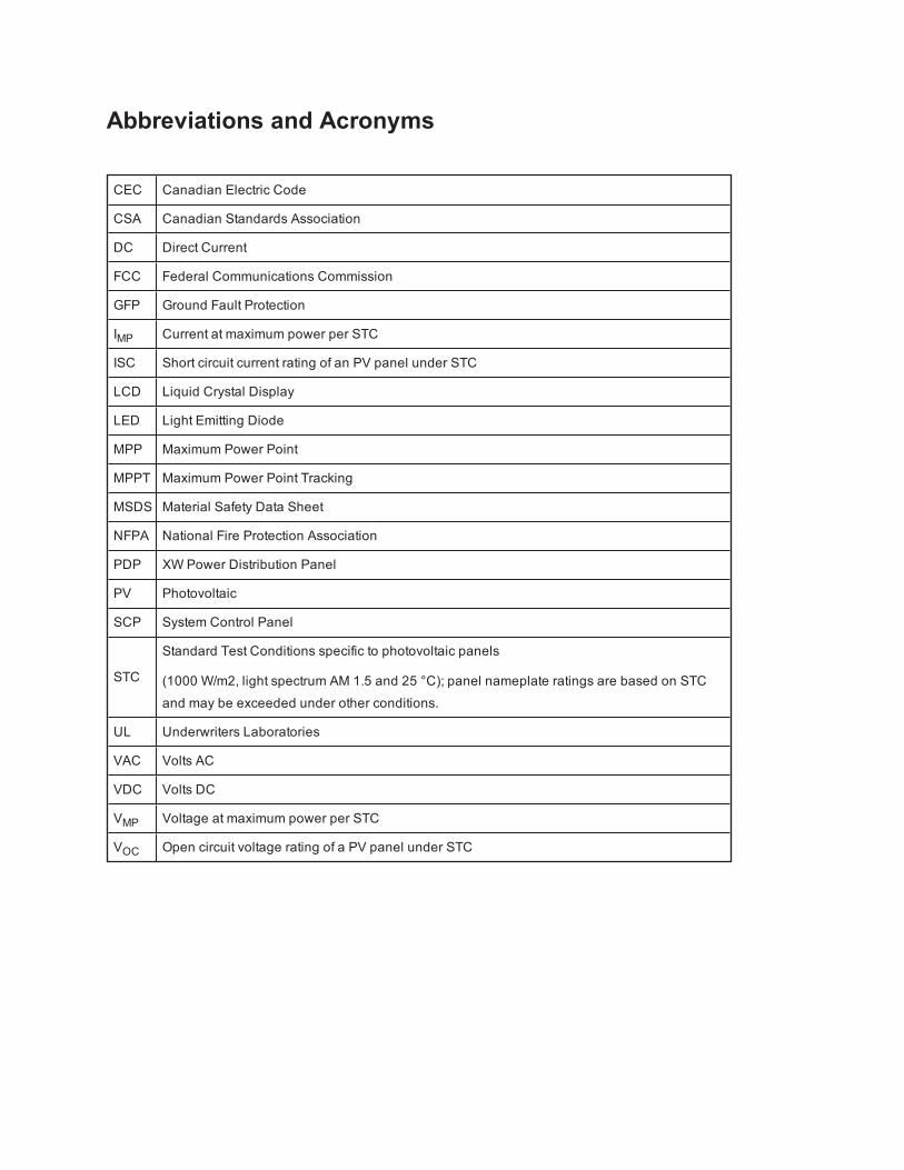
Abbreviations and Acronyms
CEC Canadian Electric Code
CSA Canadian Standards Association
DC Direct Current
FCC Federal Communications Commission
GFP Ground Fault Protection
IMP Current at maximum power per STC
ISC Short circuit current rating of an PV panel under STC
LCD Liquid Crystal Display
LED Light Emitting Diode
MPP Maximum Power Point
MPPT Maximum Power Point Tracking
MSDS Material Safety Data Sheet
NFPA National Fire Protection Association
PDP XW Power Distribution Panel
PV Photovoltaic
SCP System Control Panel
STC
Standard Test Conditions specific to photovoltaic panels
(1000 W/m2, light spectrum AM 1.5 and 25 °C); panel nameplate ratings are based on STCand may be exceeded under other conditions.
UL Underwriters Laboratories
VAC Volts AC
VDC Volts DC
VMP Voltage at maximum power per STC
VOC Open circuit voltage rating of a PV panel under STC
Related InformationYou can find information about operating the charge controller in theConextMPPT 80 andMPPT 100 Solar Charge Controller Owner's Guide. It isprovided with the charge controller and is also available at solar.schneider-electric.com.
You can findmore information about Schneider Electric as well as its productsand services at solar.schneider-electric.com.

Safety InformationImportant Information
Read these instructions carefully and look at the equipment to become familiar with thedevice before trying to install, operate, service or maintain it. The following specialmessages may appear throughout this documentation or on the equipment to warn ofpotential hazards or to call attention to information that clarifies or simplifies a procedure.
The addition of either symbol to a “Danger” or “Warning” safety labelindicates that an electrical hazard exists which will result in personalinjury if the instructions are not followed.
This is the safety alert symbol. It is used to alert you to potentialpersonal injury hazards. Obey all safety messages that follow thissymbol to avoid possible injury or death.
DANGERDANGER indicates a hazardous situation which, if not avoided,will result in death orserious injury.
WARNINGWARNING indicates a hazardous situation which, if not avoided, could result in death orserious injury.
CAUTIONCAUTION indicates a hazardous situation which, if not avoided, could result inminor ormoderate injury.
NOTICENOTICE is used to address practices not related to physical injury.
Please NoteElectrical equipment should be installed, operated, serviced, andmaintained only byqualified personnel. No responsibility is assumed by Schneider Electric for anyconsequences arising out of the use of this material.
A qualified person is one who has skills and knowledge related to the construction,installation, and operation of electrical equipment and has received safety training torecognize and avoid the hazards involved. For more information, seeAudience.
Safety Information Conext MPPT 80 and MPPT 100 Installation Guide
990-91319B This document is for use by qualified personnel 6
Safety Informationn Before using the charge controller, read all instructions and cautionary
markings on the unit, the batteries, and all appropriate sections of thismanual.
n Use of accessories not recommended or sold by themanufacturer may result ina risk of fire, electric shock, or injury to persons.
n The charge controller is designed to be permanently connected to your AC andDC electrical systems. Themanufacturer recommends that all wiring be doneby a certified technician or electrician to ensure adherence to the local andnational electrical codes applicable in your jurisdiction.
n To avoid a risk of fire and electric shock, make sure that existing wiring is ingood condition and that wire is not undersized. Do not operate the chargecontroller with damaged or substandard wiring.
n Do not operate the charge controller if it has been damaged in any way.
n This unit does not have any user-serviceable parts. Do not disassemble thecharge controller except where noted for connecting wiring and cabling. Seeyour warranty for instructions on obtaining service. Attempting to service theunit yourself may result in a risk of electrical shock or fire. Internal capacitorsremain charged after all power is disconnected.
n To reduce the risk of electrical shock, disconnect both AC and DC power fromthe inverter before attempting any maintenance or cleaning or working on anycomponents connected to the charge controller. Putting the unit in Standbymode will not reduce this risk.
n The charge controller must be provided with an equipment-groundingconductor.
n Do not expose this unit to rain, snow, or liquids of any type. This product isdesigned for indoor use only. Damp environments will significantly shorten thelife of this product and corrosion caused by dampness will not be covered bythe product warranty.
n To reduce the chance of short-circuits, always use insulated tools wheninstalling or working with this equipment. Do not leave tools inside the unit.
n Remove personal metal items such as rings, bracelets, necklaces, andwatches when working with electrical equipment.
Conext MPPT 80 and MPPT 100 Installation Guide Safety Information
7 This document is for use by qualified personnel 990-91319B

DANGERHAZARD OF ELECTRIC SHOCK, EXPLOSION, ARC FLASH, AND FIRE
n Apply appropriate personal protective equipment (PPE) and follow safe electricalwork practices. See NFPA 70E, CSA Z462, or EN 50110-1.
n This equipment must only be installed and serviced by qualified electricalpersonnel.
n Never operate energized with covers removed
n Energized from multiple sources. Before removing covers identify all sources, de-energize, lock-out, and tag-out and wait 2 minutes for circuits to discharge.
n Always use a properly rated voltage sensing device to confirm all circuits are de-energized.
Failure to follow these instructions will result in death or serious injury.
DANGERHAZARD OF ELECTRIC SHOCK, EXPLOSION, ARC FLASH, AND FIRE
n Disconnect positive and negative PV conductors before servicing. PV conductorsare a shock hazard and must be disconnected before servicing the installation.
n Normally GROUNDED conductors may be UNGROUNDED and ENERGIZEDwhen a GROUND FAULT is indicated on the front panel. Must be serviced byqualified personnel.
Failure to follow these instructions will result in death or serious injury.
WARNINGLIMITATIONS ON USE
Do not use the charge controller with life support equipment or other medicalequipment or devices.
Failure to follow these instructions can result in death, serious injury, or equipmentdamage.
NOTICELIGHTNING PROTECTION
To protect the charge controller’s insulation and conductors from damage due to asudden over-voltage surge such as a lightning strike, install a DC-rated lightning arrestoron the PV source circuits.
Failure to follow these instructions can result in equipment damage.
Safety Information Conext MPPT 80 and MPPT 100 Installation Guide
990-91319B This document is for use by qualified personnel 8
Battery Safety Information
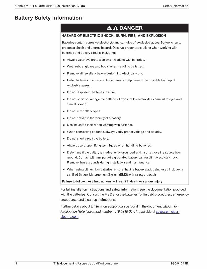
DANGERHAZARD OF ELECTRIC SHOCK, BURN, FIRE, AND EXPLOSION
Batteries contain corrosive electrolyte and can give off explosive gases. Battery circuitspresent a shock and energy hazard. Observe proper precautions when working withbatteries and battery circuits, including:
n Always wear eye protection when working with batteries.
n Wear rubber gloves and boots when handling batteries.
n Remove all jewellery before performing electrical work.
n Install batteries in a well-ventilated area to help prevent the possible buildup ofexplosive gases.
n Do not dispose of batteries in a fire.
n Do not open or damage the batteries. Exposure to electrolyte is harmful to eyes andskin. It is toxic.
n Do not mix battery types.
n Do not smoke in the vicinity of a battery.
n Use insulated tools when working with batteries.
n When connecting batteries, always verify proper voltage and polarity.
n Do not short-circuit the battery.
n Always use proper lifting techniques when handling batteries.
n Determine if the battery is inadvertently grounded and if so, remove the source fromground. Contact with any part of a grounded battery can result in electrical shock.Remove these grounds during installation and maintenance.
n When using Lithium Ion batteries, ensure that the battery pack being used includes acertified Battery Management System (BMS) with safety protocols.
Failure to follow these instructions will result in death or serious injury.
For full installation instructions and safety information, see the documentation providedwith the batteries. Consult theMSDS for the batteries for first aid procedures, emergencyprocedures, and clean-up instructions.
Further details about Lithium Ion support can be found in the document Lithium IonApplication Note (document number: 976-0319-01-01, available at solar.schneider-electric.com.
Conext MPPT 80 and MPPT 100 Installation Guide Safety Information
9 This document is for use by qualified personnel 990-91319B
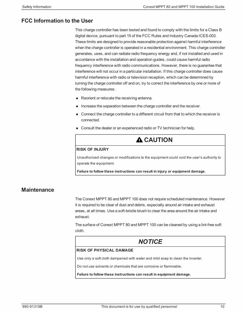
FCC Information to the UserThis charge controller has been tested and found to comply with the limits for a Class Bdigital device, pursuant to part 15 of the FCC Rules and Industry Canada ICES-003.These limits are designed to provide reasonable protection against harmful interferencewhen the charge controller is operated in a residential environment. This charge controllergenerates, uses, and can radiate radio frequency energy and, if not installed and used inaccordance with the installation and operation guides, could cause harmful radiofrequency interference with radio communications. However, there is no guarantee thatinterference will not occur in a particular installation. If this charge controller does causeharmful interference with radio or television reception, which can be determined byturning the charge controller off and on, try to correct the interference by one or more ofthe followingmeasures:
n Reorient or relocate the receiving antenna.
n Increase the separation between the charge controller and the receiver.
n Connect the charge controller to a different circuit from that to which the receiver isconnected.
n Consult the dealer or an experienced radio or TV technician for help.
CAUTIONRISK OF INJURY
Unauthorized changes or modifications to the equipment could void the user’s authority tooperate the equipment.
Failure to follow these instructions can result in injury or equipment damage.
MaintenanceThe Conext MPPT 80 andMPPT 100 does not require scheduledmaintenance. Howeverit is required to be clear of dust and debris, especially around air intake and exhaustareas, at all times. Use a soft-bristle brush to clear the area around the air intake andexhaust.
The surface of Conext MPPT 80 andMPPT 100 can be cleaned by using a lint-free softcloth.
NOTICERISK OF PHYSICAL DAMAGE
Use only a soft cloth dampened with water and mild soap to clean the inverter.
Do not use solvents or chemicals that are corrosive or flammable.
Failure to follow these instructions can result in equipment damage.
Safety Information Conext MPPT 80 and MPPT 100 Installation Guide
990-91319B This document is for use by qualified personnel 10


ContentsAudience 2
Purpose 3
Scope 3
Abbreviations and Acronyms 4
Related Information 5
Safety Information 6Safety Information 7
Battery Safety Information 9
FCC Information to the User 10
Maintenance 10
Introduction 18Features 19
Charge Controlling 20
Conext MPPT 80 600 20
Conext MPPT 100 600 20
Configurations 20
Typical Installation 20
Installation 22RequiredMaterials and Tools 23
Required Accessories 23
PV Array Requirements 23
Mounting 24
Choosing a Location 24
Removing theWiring Compartment Cover 26
Removing Knockouts 26
Mounting the Charge Controller 28
PV Grounding 29
Chassis Grounding 29
Internal Ground Fault Protection 29
Wiring 31
Connector Locations 31
Wire Size andOver-current Protection Requirements 31
Connecting the Charge Controller 34
ConnectingMultiple PV Array Strings to One Unit 37
ConnectingMultiple Units 38
Auxiliary Output Connections 38
Network Installation 39
Conext MPPT 80 and MPPT 100 Installation Guide
990-91319B This document is for use by qualified personnel 12

Installing the Battery Temperature Sensor 42
Commissioning 44
Troubleshooting 50Troubleshooting 51
Replacing the Ground Fault Protection Fuse 53
Ground Faults in a Normally Ungrounded Array 53
Specifications 56Electrical Specifications 57
MPPT Voltage Range 58
Operating Below the PV Array Voltage Full Power Range 59
Conext MPPT 80 600 59
Conext MPPT 100 600 59
Default Battery Charging Settings 60
Mechanical Specifications 61
Output Power Versus Ambient Temperature 62
Accessories 63
Conext System Control Panel 63
Conext Gateway 63
Conext Config Tool 63
Regulatory Approvals 64
Conext MPPT 80 and MPPT 100 Installation Guide
13 This document is for use by qualified personnel 990-91319B
FiguresFigure 1 Typical Installation 21
Figure 2 Minimum Clearance Requirements 25
Figure 3 Removing the wiring compartment cover 26
Figure 4 Wiring Compartment with Lexan Barrier 26
Figure 5 Knockout dimensions 27
Figure 6 Dimensions and knockout locations 28
Figure 7 Mounting the Charge Controller 29
Figure 8 Chassis ground connector 30
Figure 9 DC Terminal Connector Locations 31
Figure 10 Typical Wiring Diagram for a Negative-Grounded System (48 V Battery BankShown) 36
Figure 11 Multiple unit DC wiring 38
Figure 12 Auxiliary output vent fan application 39
Figure 13 Network terminator 40
Figure 14 Network layout 41
Figure 15 Attaching the BTS to a battery terminal 43
Figure 16 Installing the BTS 44
Figure 17 MPPT Operational Window 58
Figure 18 Maximum Expected Output Current Versus Input Voltage, Conext MPPT 80600 59
Figure 19 Maximum Expected Output Current Versus Input Voltage, Conext MPPT100 600 59
Figure 20 Output power vs. ambient temperature, Conext MPPT 80 600 62
Figure 21 Output power vs. ambient temperature, Conext MPPT 100 600 62
Conext MPPT 80 and MPPT 100 Installation Guide
990-91319B This document is for use by qualified personnel 14


TablesTable 1 Minimum clearance requirements 25
Table 2 Troubleshooting 51
Table 3 Electrical specifications 57
Table 4 Mechanical specifications 61
Conext MPPT 80 and MPPT 100 Installation Guide
990-91319B This document is for use by qualified personnel 16

Introduction
Introduction Conext MPPT 80 and MPPT 100 Installation Guide
1
Features 19
Charge Controlling 20
Conext MPPT 80 600 20
Conext MPPT 100 600 20
Configurations 20
Typical Installation 20
What's in This Chapter?

FeaturesThe Conext MPPT 80 orMPPT 100 Solar Charge Controller (charge controller) tracks themaximum power point of a PV array to deliver themaximum available current foroptimum charging of batteries. The charge controller can be used with 24 VDC and 48VDC battery systems only.
Key product features include a 600 VDC maximum input voltage, a Fast Sweep™MPPTtracking algorithm, and built-in ground fault protection. For information on additionalproduct features, see theConext MPPT 80 andMPPT 100Owner's Guide (documentpart number: 990-6214).
The high input voltage operating range allows a high-voltage and low-current PV array tobe connected to the charge controller. A high-voltage PV array configuration caneliminate the need for a combiner box and associated DC circuit breakers as well asincorporate the use of smaller AWGwire for array wiring. This simplified arrayconfiguration reduces wiring costs, installation labor costs, and allows for long home-runwiring with minimal power loss.
The Fast SweepMPPT algorithm frequently conducts a very fast sweep of the fulloperational array voltage window to dynamically determine the array’s maximum powerpoint. This feature optimizes the high energy harvest of the solar array, regardless ofconditions such as temperature or shading.
The charge controller is equipped with built-in ground fault protection for a negative,positive, or ungrounded PV array and is compatible with all PV modulemanufacturers.The charge controller regulates the available power from a PV source only. It is notdesigned to regulate power from other types of power sources.
The charge controller can be installed with a Conext SW Inverter, Conext XW+ orConext XW Pro Inverter/Charger, or as a stand alone battery charger. For PV rapidshutdown and arc fault detection functions, the charge controller can be installed with theMPPT Disconnect RS. To configure the charge controller, a Conext System ControlPanel (SCP) or Conext Gateway is also required (seeAccessories on page 63 forproduct part numbers). While both the SCP and Conext Gateway provide statusinformation and configuration capabilities, the Conext Gateway provides additionalaccess to configuration settings through a web interface.
Conext MPPT 80 and MPPT 100 Installation Guide Introduction
19 This document is for use by qualified personnel 990-91319B
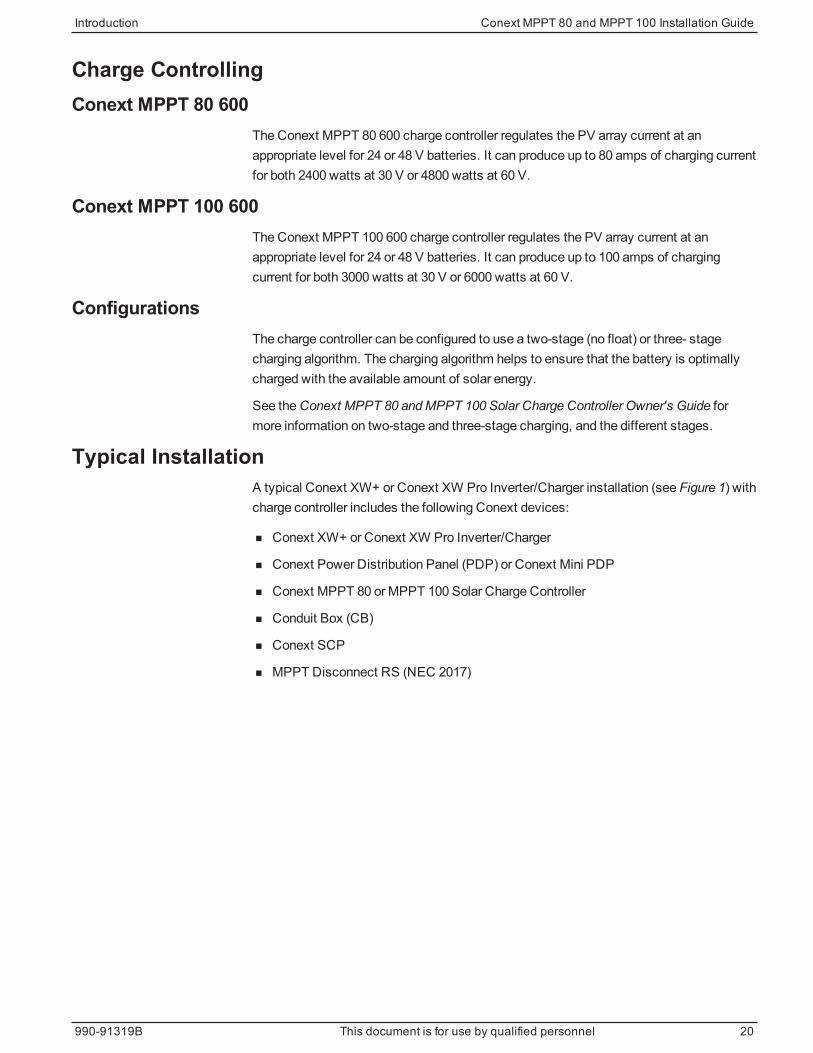
Charge ControllingConext MPPT 80 600
The Conext MPPT 80 600 charge controller regulates the PV array current at anappropriate level for 24 or 48 V batteries. It can produce up to 80 amps of charging currentfor both 2400 watts at 30 V or 4800 watts at 60 V.
Conext MPPT 100 600The Conext MPPT 100 600 charge controller regulates the PV array current at anappropriate level for 24 or 48 V batteries. It can produce up to 100 amps of chargingcurrent for both 3000 watts at 30 V or 6000 watts at 60 V.
ConfigurationsThe charge controller can be configured to use a two-stage (no float) or three- stagecharging algorithm. The charging algorithm helps to ensure that the battery is optimallycharged with the available amount of solar energy.
See theConext MPPT 80 andMPPT 100 Solar Charge Controller Owner's Guide formore information on two-stage and three-stage charging, and the different stages.
Typical InstallationA typical Conext XW+ or Conext XW Pro Inverter/Charger installation (see Figure 1) withcharge controller includes the following Conext devices:
n Conext XW+ or Conext XW Pro Inverter/Charger
n Conext Power Distribution Panel (PDP) or Conext Mini PDP
n Conext MPPT 80 orMPPT 100 Solar Charge Controller
n Conduit Box (CB)
n Conext SCP
n MPPT Disconnect RS (NEC 2017)
Introduction Conext MPPT 80 and MPPT 100 Installation Guide
990-91319B This document is for use by qualified personnel 20
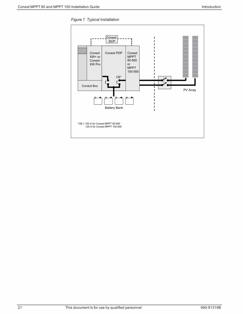
Figure 1 Typical Installation
Conduit Box
Conext PDP
*CB = 100 A for Conext MPPT 80 600 125 A for Conext MPPT 100 600
Conext XW+ orConext XW Pro
Conext MPPT80 600or MPPT100 600
CB*
PV Array
Battery Bank
Conext SCP
-+ -+ -+-+
Conext MPPT 80 and MPPT 100 Installation Guide Introduction
21 This document is for use by qualified personnel 990-91319B
Installation
Installation Conext MPPT 80 and MPPT 100 Installation Guide
2
Required Materials and Tools 23
Required Accessories 23
PV Array Requirements 23
Mounting 24
Choosing a Location 24
Removing theWiring Compartment Cover 26
Removing Knockouts 26
Mounting the Charge Controller 28
PV Grounding 29
Chassis Grounding 29
Internal Ground Fault Protection 29
Wiring 31
Connector Locations 31
Wire Size andOver-current Protection Requirements 31
Connecting the Charge Controller 34
ConnectingMultiple PV Array Strings to One Unit 37
ConnectingMultiple Units 38
Auxiliary Output Connections 38
Network Installation 39
Installing the Battery Temperature Sensor 42
Commissioning 44
What's in This Chapter?

DANGERHAZARD OF ELECTRIC SHOCK, EXPLOSION, ARC FLASH, AND FIRE
Installation of this equipment should only be planned and performed by qualified personnelin accordance with all applicable installation codes. See "Audience" on page 2 for thedefinition of qualified personnel.
Failure to follow these instructions will result in death or serious injury.
WARNINGHAZARD OF ELECTRIC SHOCK, BURNS, FIRE, AND EXPLOSION
Follow all instructions and electrical, physical, and environmental installation specificationsin this Guide.
Failure to follow these instructions can result in death, serious injury, or equipmentdamage.
Required Materials and ToolsThe followingmaterials are shipped with the charge controller:
n OneConext MPPT 80 orMPPT 100 Solar Charge Controller
n OneConext MPPT 80 andMPPT 100 Solar Charge Controller Installation Guide
n OneConext MPPT 80 andMPPT 100 Solar Charge Controller Owner's Guide
n One Factory Test Certificate
n One Battery Temperature Sensor (BTS)
n One fuse: 1 A 600 VAC/DC
n One network terminator
The following tools are required for installation:
n Phillips head screwdriver
n Wire cutters and wire strippers
Required AccessoriesA Conext System Control Panel (SCP) is required for installation of the charge controller.
However, in place of the SCP, a Conext Gateway can be used if you would like toconfigure andmonitor the charge controller through a web-interface on a PC or laptop.
For more information about accessories, seeSpecifications on page 56.
PV Array RequirementsNOTE: The following information only provides general guidelines. PV array installationis subject to installation codes and, in some areas, inspection and approval by theauthority having jurisdiction. For example, installations in the United States must becompliant with NEC and, in particular, Article 690.
Conext MPPT 80 and MPPT 100 Installation Guide Installation
23 This document is for use by qualified personnel 990-91319B

Each charge controller must be connected to its own PV array. Up to three PV arraystrings can be connected in parallel to a single charge controller. SeeConnectingMultiplePV Array Strings to One Unit on page 37.
WARNINGHAZARD OF ELECTRIC SHOCK AND FIRE
n The PV array voltage must never exceed 600 V in any condition (open circuit, coldtemperature, bright sun, etc.).
n The PV array current must never exceed 35 A for Conext MPPT 80 600, or 44 A forConext MPPT 100 600 in any condition (short circuit, hot temperature, bright sun, etc.).
Failure to follow these instructions can result in death, serious injury, or equipmentdamage.
MountingThe instructions in this chapter are applicable to a typical stand-alone installation.Installation procedures will vary according to your specific application. For specialapplications, consult a qualified Renewable Energy System Installer or a CertifiedDealer.
Choosing a Location
WARNINGHAZARD OF ELECTRIC SHOCK, BURN, FIRE, AND EXPLOSION
The charge controller must be mounted vertically and installed indoors in a dry, protectedlocation away from flammable materials, sources of high temperature, moisture, andvibration. The location must also be sheltered from direct sunlight, dust, and wind-blowndebris.
Failure to follow these instructions can result in death, serious injury, or equipmentdamage.
Flammable or combustible materials are defined as “any material containing wood,compressed paper, cellulose, plant fibers, plastics, liquids, or other material that willignite and burn, whether flame-proofed or not” according to the NFPA. Flammable liquidsare defined as “any liquid whose flash point does not exceed 100 °F (38 °C).” Examplesof flammable liquids are gasoline, methanol, and ether.
When choosing a wall to install the charge controller, choose a wall that is not considereda flammablematerial such as concrete, brick, or metal.
WARNINGHAZARD OF EXPLOSION
Do not install the charge controller in a sealed compartment containing batteries.
Failure to follow these instructions can result in death, serious injury, or equipmentdamage.
Installation Conext MPPT 80 and MPPT 100 Installation Guide
990-91319B This document is for use by qualified personnel 24

NOTICECHARGE CONTROLLER DAMAGE
The charge controller can overheat if installed in a sealed, indoor enclosure. Do not installthe charge controller in a sealed compartment.
Failure to follow these instructions can result in equipment damage.
To help ensure optimal and safe operation, make sure there is adequate clearance aroundthe charge controller. See Table 1 and Figure 2. If clearances are reduced below theseminimums, charging performancemight be impaired.
Location Minimum Clearance
Above
and below
6 inches (150 mm). Do not mount charge controllers in a verticalstack.
In frontSufficient room to allow for easy access to see the LEDs and toperform maintenance.
Sides
No clearance requirement. One charge controller can be mountedon the side of the Conext Power Distribution Panel (PDP) (PartNumber 865-1015-01). For more information, see the Conext XW+or Conext XW Pro Inverter/Charger Installation Guide. Otherinstallations must follow the guidelines in this Guide.
Table 1 Minimum clearance requirements
Figure 2 Minimum Clearance Requirements
Conext MPPT 80 and MPPT 100 Installation Guide Installation
25 This document is for use by qualified personnel 990-91319B

Removing the Wiring Compartment Cover
DANGERHAZARD OF ELECTRIC SHOCK, EXPLOSION, ARC FLASH, AND FIRE
Before removing the wiring compartment cover, make sure all electrical power sourceshave been disconnected for at least two minutes. Before energizing the charge controller,make sure the wiring compartment cover has been replaced and all fasteners are in place.
Failure to follow these instructions will result in death or serious injury.
Beforemounting, remove the wiring compartment cover to access themounting holesand the wiring terminals. The wiring compartment cover is secured with two screws onthe front of the charge controller (see ).
Figure 3 Removing the wiring compartment cover
Remove two screws to
access the wiring terminals.
The wiring compartment (see Figure 4) contains a flexible Lexan™ barrier used tosegregate low voltage battery and high voltage PV wire routing. In some instances, youmust manipulate this barrier to provide a passage for the battery or PV cables which runthrough the wiring compartment. In this scenario, youmust take care to avoidintermingling the high voltage PV and low voltage battery wires.
Figure 4 Wiring Compartment with Lexan Barrier
Lexan barrier
Removing KnockoutsFourteen knockouts are provided for conduit or cable entry into the charge controller (seeFigure 5 and Figure 6):
Installation Conext MPPT 80 and MPPT 100 Installation Guide
990-91319B This document is for use by qualified personnel 26
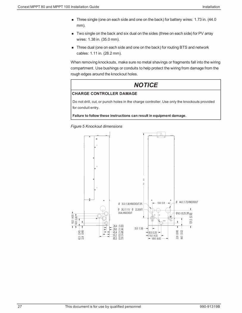
n Three single (one on each side and one on the back) for battery wires: 1.73 in. (44.0mm).
n Two single on the back and six dual on the sides (three on each side) for PV arraywires: 1.38 in. (35.0mm).
n Three dual (one on each side and one on the back) for routing BTS and networkcables: 1.11 in. (28.2mm).
When removing knockouts, make sure nometal shavings or fragments fall into the wiringcompartment. Use bushings or conduits to help protect the wiring from damage from therough edges around the knockout holes.
NOTICECHARGE CONTROLLER DAMAGE
Do not drill, cut, or punch holes in the charge controller. Use only the knockouts providedfor conduit entry.
Failure to follow these instructions can result in equipment damage.
Figure 5 Knockout dimensions
26.4 (1.03)29.0 (1.14)45.4 (1.78)55.2 (2.17)85.5 (3.37)22
.8 (0
.90)
62.3
(2.4
5)
82.8
(3.2
6)
102.
5 (4
.03)
Ø 6.5 (0.25) 2PL
150.0 (5.9)
35.0 (1.38)
85.0 (3.35)110.0 (4.33)
169.0 (6.65) 22.8
(0.9
0)
66.5
(3.5
2)
131.
5 (5
.18)
719.
0 (2
8.3)
Ø 28.2 (1.11)/ Ø 22.2(0.87)
DUAL KNOCKOUT
Ø 35.0 (1.38) KNOCKOUT 2PLØ 44.0 (1.73) KNOCKOUT
Conext MPPT 80 and MPPT 100 Installation Guide Installation
27 This document is for use by qualified personnel 990-91319B
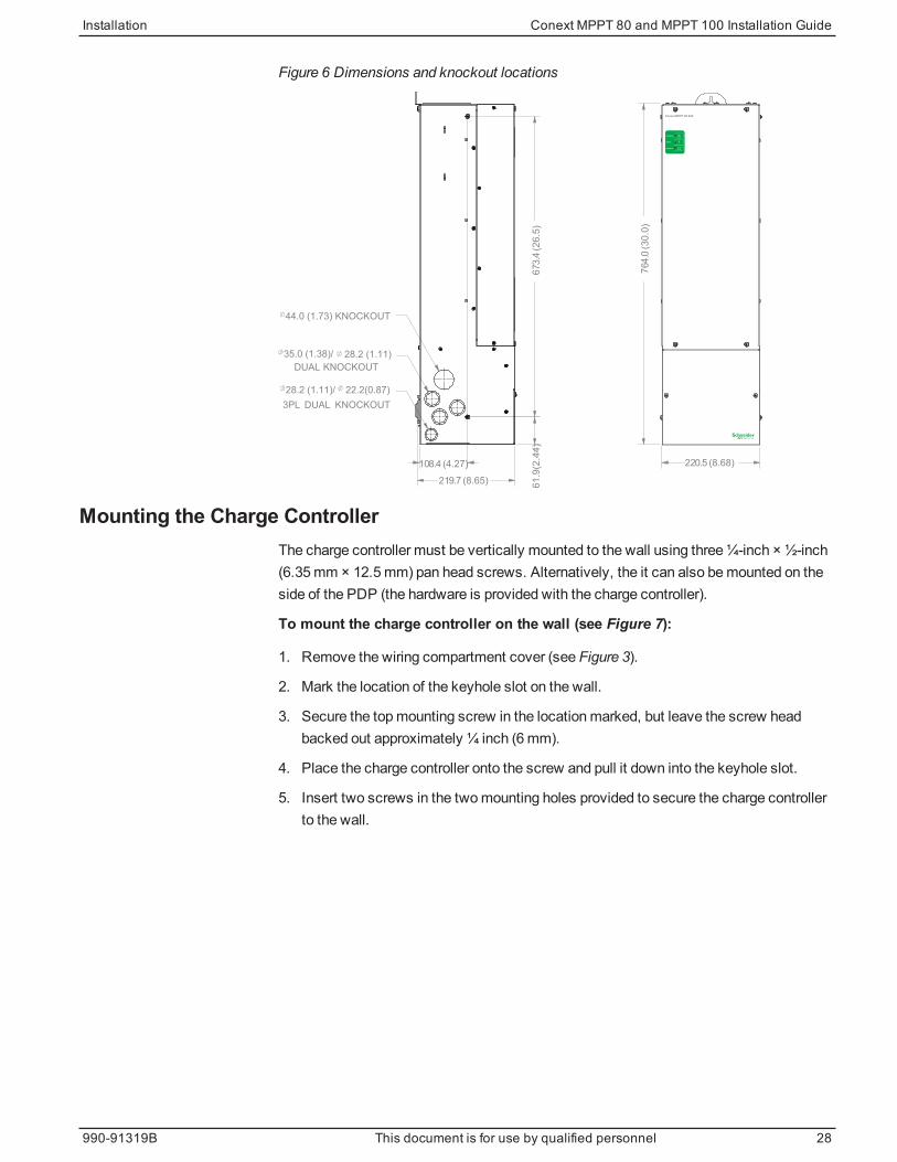
Figure 6 Dimensions and knockout locations
764.0
(3
0.0
)
220.5 (8.68)
44.0 (1.73) KNOCKOUT
DUAL KNOCKOUT
28.2 (1.11)/ 22.2(0.87)
35.0 (1.38)/ 28.2 (1.11) DUAL KNOCKOUT
3PL
108.4 (4.27)
61
.9 (2
.44
)6
73.4
(2
6.5
)
219.7 (8.65)
Conext MPPT 80 600
!Event
Equalize
Charging
Mounting the Charge ControllerThe charge controller must be vertically mounted to the wall using three¼-inch × ½-inch(6.35mm × 12.5mm) pan head screws. Alternatively, the it can also bemounted on theside of the PDP (the hardware is provided with the charge controller).
To mount the charge controller on the wall (see Figure 7):
1. Remove the wiring compartment cover (see Figure 3).
2. Mark the location of the keyhole slot on the wall.
3. Secure the topmounting screw in the locationmarked, but leave the screw headbacked out approximately ¼ inch (6mm).
4. Place the charge controller onto the screw and pull it down into the keyhole slot.
5. Insert two screws in the twomounting holes provided to secure the charge controllerto the wall.
Installation Conext MPPT 80 and MPPT 100 Installation Guide
990-91319B This document is for use by qualified personnel 28
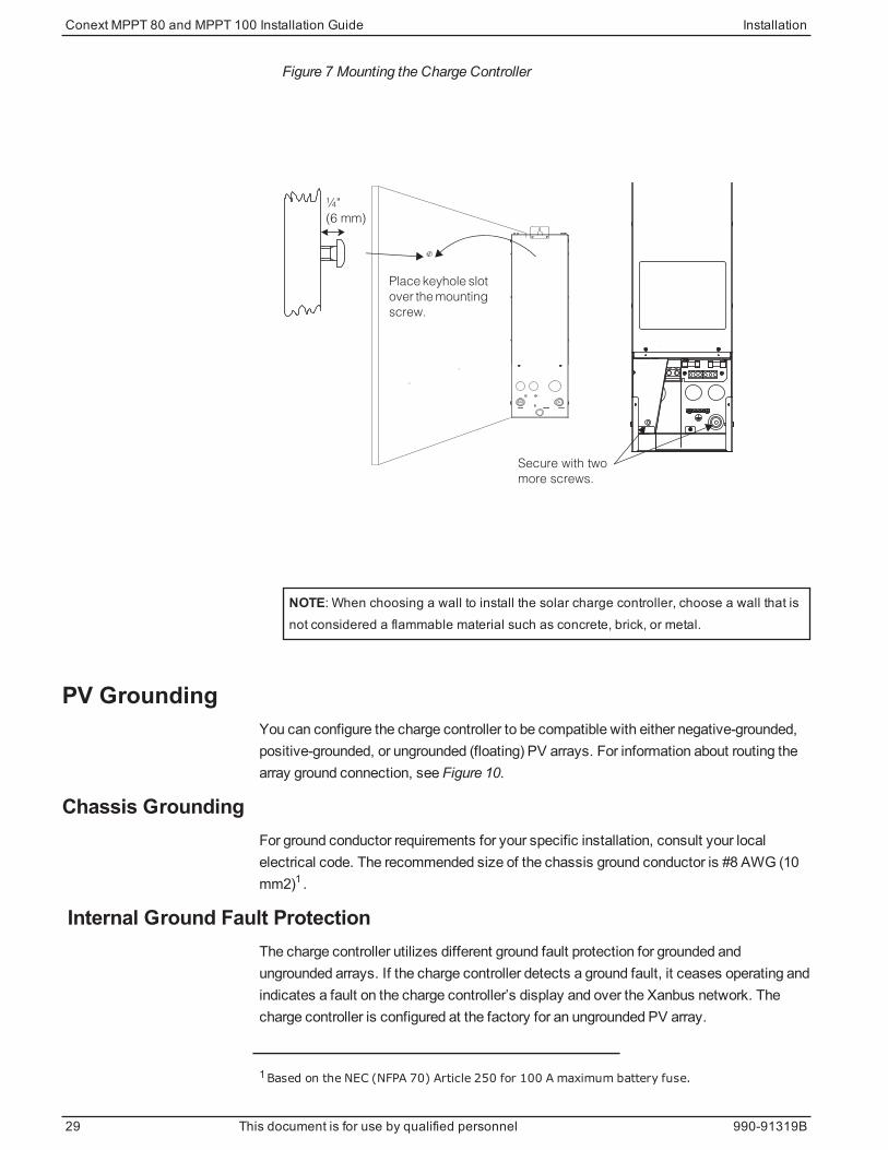
Figure 7 Mounting the Charge Controller
¼"
Secure with two
more screws.
(6 mm)
Place keyhole slot
over the mounting
screw.
NOTE: When choosing a wall to install the solar charge controller, choose a wall that isnot considered a flammable material such as concrete, brick, or metal.
PV GroundingYou can configure the charge controller to be compatible with either negative-grounded,positive-grounded, or ungrounded (floating) PV arrays. For information about routing thearray ground connection, see Figure 10.
Chassis GroundingFor ground conductor requirements for your specific installation, consult your localelectrical code. The recommended size of the chassis ground conductor is #8 AWG (10mm2)1 .
Internal Ground Fault ProtectionThe charge controller utilizes different ground fault protection for grounded andungrounded arrays. If the charge controller detects a ground fault, it ceases operating andindicates a fault on the charge controller’s display and over the Xanbus network. Thecharge controller is configured at the factory for an ungrounded PV array.
1Based on the NEC (NFPA 70) Article 250 for 100 A maximum battery fuse.
Conext MPPT 80 and MPPT 100 Installation Guide Installation
29 This document is for use by qualified personnel 990-91319B
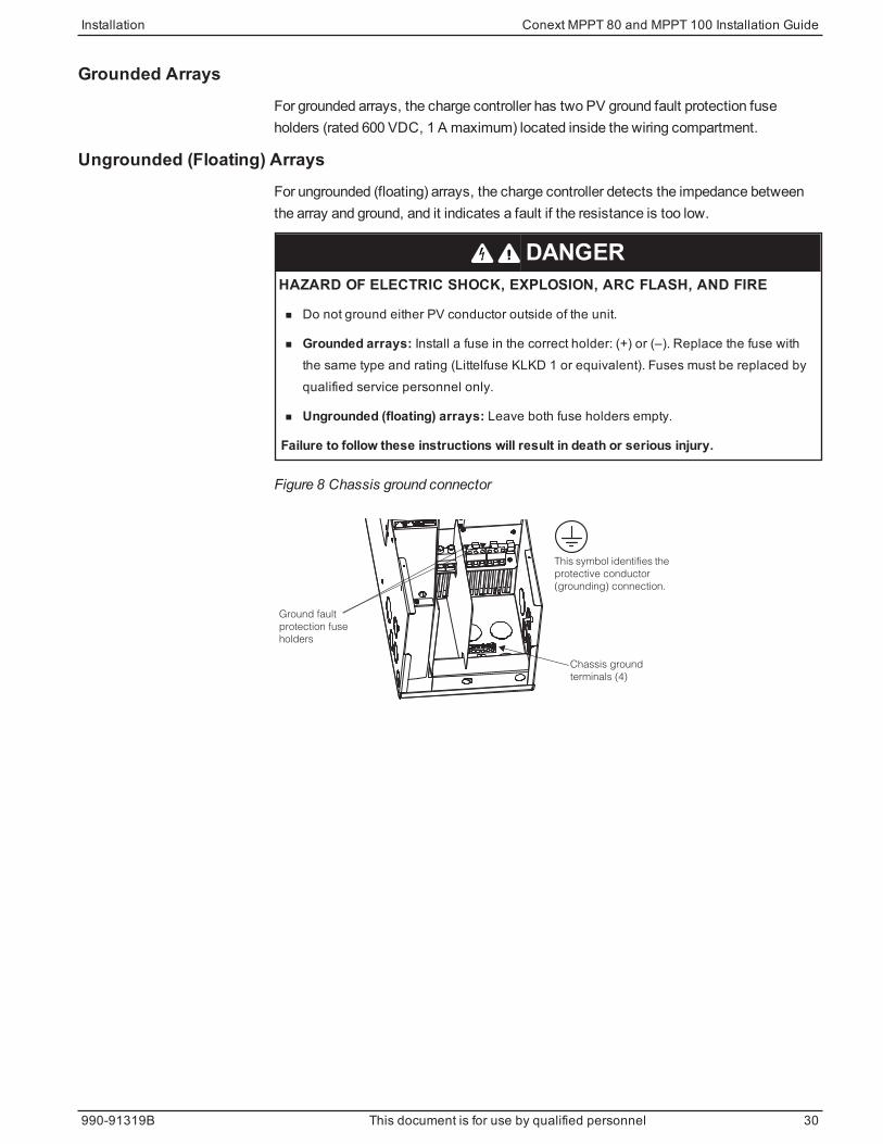
Grounded ArraysFor grounded arrays, the charge controller has two PV ground fault protection fuseholders (rated 600 VDC, 1 A maximum) located inside the wiring compartment.
Ungrounded (Floating) ArraysFor ungrounded (floating) arrays, the charge controller detects the impedance betweenthe array and ground, and it indicates a fault if the resistance is too low.
DANGERHAZARD OF ELECTRIC SHOCK, EXPLOSION, ARC FLASH, AND FIRE
n Do not ground either PV conductor outside of the unit.
n Grounded arrays: Install a fuse in the correct holder: (+) or (–). Replace the fuse withthe same type and rating (Littelfuse KLKD 1 or equivalent). Fuses must be replaced byqualified service personnel only.
n Ungrounded (floating) arrays: Leave both fuse holders empty.
Failure to follow these instructions will result in death or serious injury.
Figure 8 Chassis ground connector
Chassis ground
terminals (4)
Ground fault
This symbol identifies the
protective conductor
(grounding) connection.
holders
protection fuse
Installation Conext MPPT 80 and MPPT 100 Installation Guide
990-91319B This document is for use by qualified personnel 30

WiringThe following sections provide information about wiring.
Connector LocationsTerminal connectors for DC wiring are located inside the wiring compartment. Labelsabove the DC wiring terminals identify all the connection points. See Figure 9.
Figure 9 DC Terminal Connector Locations
BATTERY+
_NEG. GND PV.
PV- PV+
POS. GND PV.
XANBUSXANBUS BTS AUX
TERMINAL TORQUE
25 lbf.in (2.8 Nm) 15 lbf.in (1.7 Nm)
TERMINAL TORQUE
A label providing details on each connector and torque requirements for each terminal isaffixed to the inside of the wiring compartment cover plate.
Wire Size and Over-current Protection Requirements
WARNINGHAZARD OF ELECTRIC SHOCK, ENERGY, AND FIRE
The wiring, over-current protection devices (fuses and circuit breakers), and installationmethods used must conform to all applicable code requirements. Wiring must be protectedfrom physical damage with appropriate methods such as the use of conduit and strain reliefclamps. To prevent intermingling with hazardous voltage-level wiring, the BTS, auxiliaryoutput, and network cables must pass through a different conduit than the PV and batterycables.
Failure to follow these instructions can result in death, serious injury, or equipmentdamage.
PV Current Rating and Wire GaugeTheminimum wire size is determined by the specific installation, in particular, the shortcircuit current available from the panel array. It is important that a qualified installerdetermine the correct wire size for the specific installation and the local electrical codes.The wire temperature rating (for the purpose of ampacity calculation) must not exceed75°C (167°F) in order to maintain compatibility with terminal blocks, breakers anddisconnects.
Conext MPPT 80 and MPPT 100 Installation Guide Installation
31 This document is for use by qualified personnel 990-91319B
Over-current Protection
WARNINGHAZARD OF ELECTRIC SHOCK, ENERGY, AND FIRE
Over-current protection must be provided, external to the unit, to protect the battery wiring.External disconnecting means must also be provided for both the PV and battery circuits.Consult applicable electrical codes to establish the correct fuse or circuit breaker ratingsand for required locations of protection and disconnecting means.
Failure to follow these instructions can result in death, serious injury, or equipmentdamage.
Battery Circuit
The DC-rated fuse or circuit breaker between the battery and the charge controller mustbe rated—at minimum—100 A for Conext MPPT 80 600 and 125 A for Conext MPPT 100600, andmust not exceed the allowable over-current protection rating for the size of wirebeing used, in accordance with applicable electrical codes.
If a fuse is used for over-current protection, a disconnect switchmust also be providedbetween the fuse and the source of supply (the battery). If a circuit breaker is used, it willserve both purposes of disconnection and overcurrent protection.
PV Circuit
DANGERHAZARD OF ELECTRIC SHOCK
The PV array will produce a hazardous voltage with even a small amount of light.Appropriate measures must be taken to prevent electric shock.
Failure to follow these instructions will result in death or serious injury.
WARNINGHAZARD OF ELECTRIC SHOCK, ENERGY, AND FIRE
PV wiring must be done by qualified personnel and in accordance with local electricalcodes.
Failure to follow these instructions can result in death, serious injury, or equipmentdamage.
A properly rated PV disconnect switch is mandatory between the PV array and thecharge controller, and it must be rated for 600 VDC and have a sufficient current rating foryour specific installation.
If the PV array is configured in just one or two strings, then a single 600V disconnectswitchmay be used. If the short circuit current rating of the solar array does not exceed24A under Standard Test Conditions, then the switchmay be rated for 30A. If a largerarray is used, then a 60A switchmay be required. Schneider Electric offers the followingoptions:
Installation Conext MPPT 80 and MPPT 100 Installation Guide
990-91319B This document is for use by qualified personnel 32
n 600V 30A, Square D HU361
n 600V 60A, Square D HU362
n 600V 64A, Schneider Electric MPPT Disconnect RS (865-1036), offers two channelsat 32A each. Each stringmust not exceed 25.6A Isc @ STC
When three or more PV array strings connected to one charge controller, each stringmust be fused before being combined at the PV input terminal connector inside the wiringcompartment. SeeConnectingMultiple PV Array Strings to One Unit on page 37 for moreinformation.
You can use separate disconnect switches for each PV string and combine these in thecharge controller, as long as the following conditions aremet:
n Each PV string is fused.
n All disconnects are placed side by side, so that it is clear that all need to be thrown fora complete and visible PV disconnect.
Alternatively, the array strings may be fused, combined, and fed through a singledisconnect switch.
Conext MPPT 80 and MPPT 100 Installation Guide Installation
33 This document is for use by qualified personnel 990-91319B
Connecting the Charge ControllerThe following procedure is illustrated in Figure 10.
DANGERHAZARD OF ELECTRIC SHOCK
Whenever a PV array is exposed to light, a shock hazard exists at the output wires orexposed terminals. Open the array disconnect switch before making the connections.
Failure to follow these instructions will result in death or serious injury.
To connect the charge controller in a negative-grounded system:
1. Make sure the PV array disconnect and battery disconnect are turned off.
2. Install a cable clamp into each knockout being used.
NOTICEREVERSE POLARITY DAMAGE
Before energizing the charge controller from either the PV array or from the battery,check the polarity of all power connections. Positive (+) must be connected to positive(+). Negative (–) must be connected to negative (–).
Failure to follow these instructions can result in equipment damage.
3. Ground the charge controller: connect a grounding conductor between a chargecontroller ground lug and the grounding electrode (see Figure 10).
4. Connect the PV array’s negative (–) output to the charge controller terminal markedPV –.
5. Connect the PV array’s positive (+) output to the PV array disconnect.
6. Route another positive (+) cable from the other end of the PV array disconnect to thecharge controller terminal marked PV +.
7. Connect the negative (–) battery cable to the charge controller terminal marked BAT–.
8. Connect a positive (+) cable from the charge controller terminal marked BAT + to thebattery disconnect.
9. Connect a second positive (+) cable from the other side of the battery disconnect tothe positive (+) battery terminal.
10. Torque the charge controller’s battery terminals to 25 lbf.in (2.8 Nm) and the PVterminals to 15 lbf.in (1.7 Nm). Allow some slack on the cables within the chargecontroller and secure the wiring with strain reliefs or cable clamps.
To connect the charge controller in a positive-grounded or floating system:
◆ Follow the same steps described above for a negative-grounded charge controllerinstallation except modify the location of the PV array disconnect switch as follows:
Installation Conext MPPT 80 and MPPT 100 Installation Guide
990-91319B This document is for use by qualified personnel 34

n For positive-grounded systems, the PV array disconnect switchmust be in thenegative conductor.
n For floating systems, the PV array disconnect switchmust be a 2-pole typedisconnect, connected in both the positive and negative conductors as per applicableelectrical code in the United States and Canada.
In general, the same rules apply for disconnect switches as for battery circuits: theymust be located in all ungrounded conductors. Requirements vary so consult applicablecodes.
NOTICEDAMAGE FROM LIGHTNING
To protect the charge controller’s insulation and conductors from damage due to a suddenover-voltage surge such as a lightning strike, install a DC-rated lightning arrestor on the DCinput line.
Failure to follow these instructions can result in equipment damage.
NOTE:
n The positive or negative of the battery can be grounded independent of the arraygrounding.
n Grounding and disconnect locations will vary according to system design and localelectrical codes.
Conext MPPT 80 and MPPT 100 Installation Guide Installation
35 This document is for use by qualified personnel 990-91319B
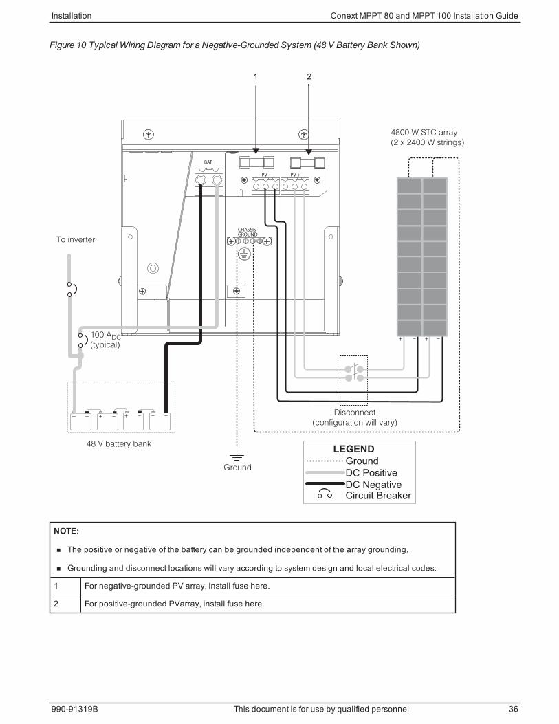
Figure 10 Typical Wiring Diagram for a Negative-Grounded System (48 V Battery Bank Shown)
LEGEND
CHASSIS
PV -
GROUND
BAT
PV +
Ground
DC Positive
DC NegativeCircuit Breaker
Disconnect
(configuration will vary)
48 V battery bank
To inverter
Ground
4800 W STC array
(2 x 2400 W strings)
100 ADC
(typical)
1 2
NOTE:
n The positive or negative of the battery can be grounded independent of the array grounding.
n Grounding and disconnect locations will vary according to system design and local electrical codes.
1 For negative-grounded PV array, install fuse here.
2 For positive-grounded PVarray, install fuse here.
Installation Conext MPPT 80 and MPPT 100 Installation Guide
990-91319B This document is for use by qualified personnel 36

Connecting Multiple PV Array Strings to One UnitThe charge controller has two three-pole PV connectors, allowing up to three PV arraystrings to be directly connected in the charge controller. These input connectors canaccept #6 to #14 AWG (13.5 to 2.5mm2) solid or stranded wire.
WARNINGHAZARD OF FIRE
n As per applicable electrical codes, fuses are required when paralleling (combining)more than two PV strings.
n Fuses must be installed in a combiner box or in a PV array disconnect switch.
n These items are not provided with the charge controller.
Failure to follow these instructions can result in death, serious injury, or equipmentdamage.
NOTICEDAMAGE FROM LIGHTNING
To protect the charge controller’s insulation and conductors from damage due to a suddenover-voltage surge such as a lightning strike, install a DC-rated lightning arrestor on the DCinput line.
Failure to follow these instructions can result in equipment damage.
Conext MPPT 80 and MPPT 100 Installation Guide Installation
37 This document is for use by qualified personnel 990-91319B
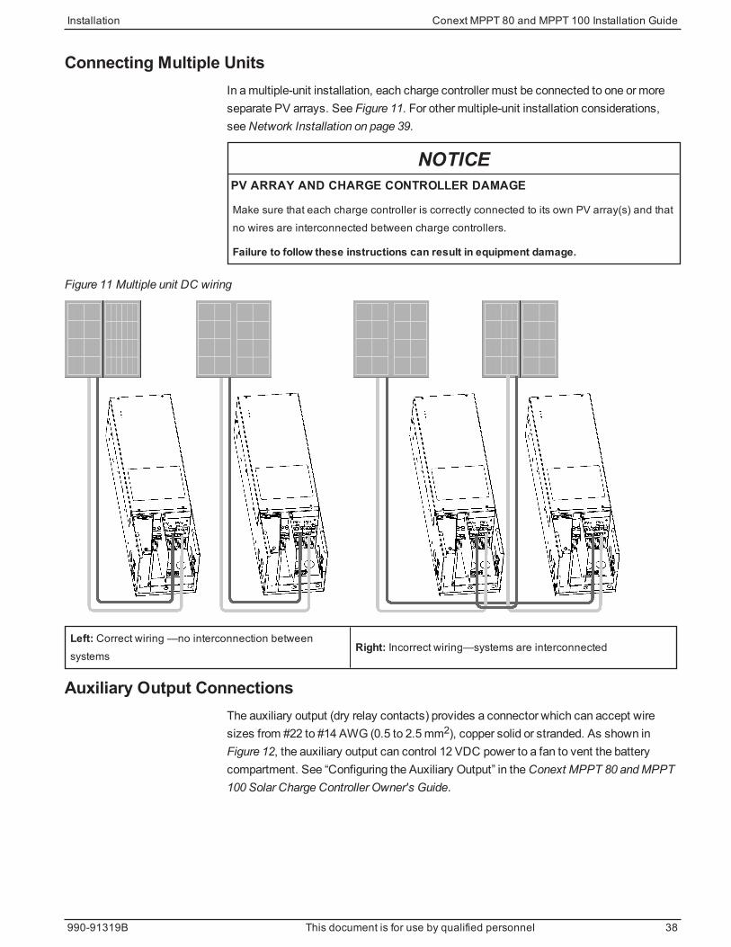
Connecting Multiple UnitsIn amultiple-unit installation, each charge controller must be connected to one or moreseparate PV arrays. See Figure 11. For other multiple-unit installation considerations,seeNetwork Installation on page 39.
NOTICEPV ARRAY AND CHARGE CONTROLLER DAMAGE
Make sure that each charge controller is correctly connected to its own PV array(s) and thatno wires are interconnected between charge controllers.
Failure to follow these instructions can result in equipment damage.
Figure 11 Multiple unit DC wiring
Left: Correct wiring —no interconnection betweensystems
Right: Incorrect wiring—systems are interconnected
Auxiliary Output ConnectionsThe auxiliary output (dry relay contacts) provides a connector which can accept wiresizes from #22 to #14 AWG (0.5 to 2.5mm2), copper solid or stranded. As shown inFigure 12, the auxiliary output can control 12 VDC power to a fan to vent the batterycompartment. See “Configuring the Auxiliary Output” in theConext MPPT 80 andMPPT100 Solar Charge Controller Owner's Guide.
Installation Conext MPPT 80 and MPPT 100 Installation Guide
990-91319B This document is for use by qualified personnel 38

WARNINGHAZARD OF ELECTRIC SHOCK AND FIRE
The auxiliary NO and NC dry contacts are rated up to 60 VDC and up to 8 A. Do not exposethe auxiliary contacts to voltages or currents higher than this rating. Provide external over-current protection rated at 8 A maximum.
Failure to follow these instructions can result in death, serious injury, or equipmentdamage.
Figure 12 Auxiliary output vent fan application
-+
BATTERY+
_NEG. GND PV.
PV- PV+
POS. GND PV.
XANBUSXANBUS BTS AUX
TERMINAL TORQUE
25 lbf.in (2.8 Nm) 15 lbf.in (1.7 Nm)
TERMINAL TORQUE
Aux terminals (from left to right): COMMON | NO | NC
Network InstallationThe charge controller is a Xanbus-enabled device. Xanbus is a network communicationssystem which allows the charge controller to communicate settings and statusinformation to other Xanbus-enabled devices.
Xanbus connections betweenmultiple charge controllers allow information about eachcharge controller and its associated PV array to be communicated among all of thecharge controllers in the system. Information about the entire system can be viewed onthe SCP or Conext Gateway.
For example, in a two-charge controller system, if charge controller #1 is producing 1500W and charge controller #2 is producing 2000W, the SCP displays a total system powerof 3500W. The accumulated amp hours and kilowatt hours produced by each chargecontroller for that day is also displayed. Networked charge controllers can also sharebattery temperature information if a single BTS is connected to a charge controller (orConext XW+ or Conext XW Pro Inverter/Charger) in the system.
Network ComponentsA Xanbus network consists of the following components:
Conext MPPT 80 and MPPT 100 Installation Guide Installation
39 This document is for use by qualified personnel 990-91319B

n Xanbus-enabled devices:
l Conext MPPT 80 orMPPT 100 Solar Charge Controller
l Conext XW+ or Conext XW Pro Inverter/Charger
l Conext Automatic Generator Start
l Conext System Control Panel or Conext Gateway
l MPPT Disconnect RS
n Xanbus power supply—an embedded power supply in the charge controller providesup to 7W of power to the Xanbus network to power one SCP and AGS, not includingthe auxiliary supply.
To reduce tare losses at night, you can configure the charge controller to shut off theXanbus power supply after sunset. See “Disabling Power Supplies at Night” in theConext MPPT 80 andMPPT 100Owner's Guide for more information.
n Network cables—each Xanbus-enabled device is connected by a standard Ethernet(CAT 5/CAT 5e) patch cable. Do not use crossover cable.
n Network terminators (see Figure 13)—the Xanbus network must be properlyterminated at each end to help ensure communication signal quality.
Network terminators plug into network ports on Xanbus-enabled devices. The chargecontroller ships with one terminator. Depending on your network layout, thisterminator might need to be inserted into another device elsewhere in the network.Two network terminators are required for all Xanbus network configurations.
Figure 13 Network terminator
Network LayoutXanbus-enabled devices are connected with separate lengths of cable. The devices ateach end of the chainmust have a terminator inserted into their open network ports, asshown in Figure 14. Total cable length for the Xanbus network must not exceed 131 feet(40m).
Installation Conext MPPT 80 and MPPT 100 Installation Guide
990-91319B This document is for use by qualified personnel 40

Figure 14 Network layout
1 Network terminator
2 Charge Controller cable
3 Cable to next device
Connecting Network Cables Between Multiple Units
WARNINGHAZARD OF ELECTRIC SHOCK
Do not route the network cables with the same conduit or panel as the PV or battery inputand output cables, and make sure the network cables are not intermingled with otherconductors in those systems.
Failure to follow these instructions can result in death, serious injury, or equipmentdamage.
Dual knockouts on the back and sides of the charge controller are provided for routing theXanbus network cable (see Figure 5 on page 27). See Figure 9 on page 31 for the locationof the charge controller’s network ports.
NOTICERISK OF EQUIPMENT DAMAGE
n Connect only Xanbus-enabled devices. Although the cabling and connectors used inthis network system are the same as ethernet connectors, this network is not an ethernetsystem.
n Do not connect one end of the network to the other to make a ring or loop.
Failure to follow these instructions can result in equipment damage.
To connect network cables betweenmultiple charge controllers:
1. Remove the wiring compartment cover from each charge controller (seeRemovingtheWiring Compartment Cover on page 26).
2. Remove a knockout from the back or either side of the unit, and then install anappropriately sized strain relief bushing for the network cable.
3. Connect the network cable to a network port in charge controller #1.
4. Route the cable to charge controller #2.
Conext MPPT 80 and MPPT 100 Installation Guide Installation
41 This document is for use by qualified personnel 990-91319B
5. Connect the network cable to a network port in charge controller #2.
6. Connect another network cable to charge controller #2, and then route the cable to thenext device in the network.
7. Make sure the factory-supplied network terminators are inserted into the emptynetwork ports in the devices at the beginning and end of the network.
There should be no empty network ports in any of the charge controllers.
Installing the Battery Temperature Sensor
WARNINGRISK OF BATTERY DAMAGE
Always install and connect the Battery Temperature Sensor (BTS). See the note directlybelow.
Failure to follow these instructions can result in death, serious injury, or equipmentdamage.
NOTE: For all BTS compatible Xanbus-enabled devices in the system, at least one BTSmust be separately installed for each device type associated with a battery.
If there is a group of the same devices forming amulti-unit setup, only one BTS isrequired per device type connected to the same battery (sameDC association).
See the installation guide of each device for BTS installation instructions.
Installing a BTS is recommended for optimum charging performance and battery life. If aBTS is not installed and the batteries must operate in hot or cold conditions, manuallyadjust the temperature settings to suit the conditions. See “Configuring BatteryCharacteristics and Battery Charging” in theConext MPPT 80 andMPPT 100Owner'sGuide.
All networked Xanbus devices share battery temperature information. If there aremultiplebattery banks andmore than one BTS is used within the system, then the highestreported temperature will be used as the battery temperature for the temperaturecompensation value of the battery charge algorithm.
See Figure 9 on page 31 for the location of the BTS port. Dual knockouts on the back andsides of the charge controller are provided for routing the BTS cable (see Figure 5 on page27).
NOTE: If the sensor cable is damaged and the wires are shorted, the charge controllerregisters a battery over temperature fault condition. If the BTS wires have been cut, thecharge controller assumes that the BTS is not connected. A replacement BTS can beordered from themanufacturer (part number 808-0232-02).
To install the BTS:
1. Remove the charge controller’s wiring compartment cover (seeRemoving theWiringCompartment Cover on page 26).
Installation Conext MPPT 80 and MPPT 100 Installation Guide
990-91319B This document is for use by qualified personnel 42

2. Remove a knockout from the back or either side of the charge controller, and theninstall an appropriately-sized strain relief bushing for the BTS cable.
3. Connect the ring terminal on the BTS directly to the negative battery terminal orpositive battery terminal, or use the adhesive backing on the sensor back to attachthe sensor to any side of the battery to bemonitored.
Figure 15 Attaching the BTS to a battery terminal
4. If connecting to the battery terminal, make sure the BTS does not prevent the powerwiring frommaking the best possible contact with the battery terminal. If using theadhesive backing, install the BTS on the side of the battery below the electrolytelevel. It is best to place the sensor between batteries and place the batteries in aninsulated box to reduce the influence of the ambient temperature outside the batteryenclosure.
WARNINGHAZARD OF ELECTRIC SHOCK
The BTS cable must not pass through the same conduit used for PV wiring and batterycables.
Failure to follow these instructions can result in death, serious injury, or equipmentdamage.
5. Pass the other end of the BTS cable through the knockout and strain relief bushing onthe charge controller, and then insert the BTS plug into the BTS RJ-11 port.
Conext MPPT 80 and MPPT 100 Installation Guide Installation
43 This document is for use by qualified personnel 990-91319B
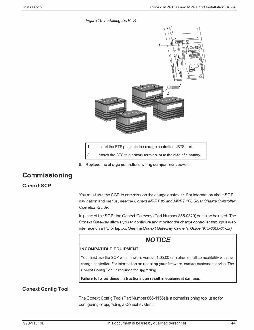
Figure 16 Installing the BTS
+
+
–
–+
+
–
–
1
2
1 Insert the BTS plug into the charge controller’s BTS port.
2 Attach the BTS to a battery terminal or to the side of a battery.
6. Replace the charge controller’s wiring compartment cover.
CommissioningConext SCP
Youmust use the SCP to commission the charge controller. For information about SCPnavigation andmenus, see theConext MPPT 80 andMPPT 100 Solar Charge ControllerOperation Guide.
In place of the SCP, the Conext Gateway (Part Number 865-0329) can also be used. TheConext Gateway allows you to configure andmonitor the charge controller through a webinterface on a PC or laptop. See theConext Gateway Owner's Guide (975-0806-01-xx).
NOTICEINCOMPATIBLE EQUIPMENT
You must use the SCP with firmware version 1.05.00 or higher for full compatibility with thecharge controller. For information on updating your firmware, contact customer service. TheConext Config Tool is required for upgrading.
Failure to follow these instructions can result in equipment damage.
Conext Config ToolThe Conext Config Tool (Part Number 865-1155) is a commissioning tool used forconfiguring or upgrading a Conext system.
Installation Conext MPPT 80 and MPPT 100 Installation Guide
990-91319B This document is for use by qualified personnel 44

Before you begin, make sure you have all important system information such as thenominal battery voltage, battery type, and battery bank capacity available.
To commission one or more charge controllers:
1. Setting the Device Number on page 45
2. Configuring Connections and Charger Settings on page 46
3. If commissioningmultiple charge controllers:Copying Settings to Another ChargeController on page 47
4. Starting the Charge Controller on page 48
When commissioningmultiple charge controllers on the same Xanbus network, makesure to set a unique device number and the correct battery connection. The connection isimportant to define so that system totals and other related information are displayedaccurately.
Setting the Device NumberTo set a device number for the charge controller:
1. Make sure an SCP is attached to the Xanbus network.
2. Close the DC disconnect. When a charge controller is powered up, it will begincommunicating with the SCP and be ready for configuration through the SCP. Do notapply PV power at this point.
3. On the SCP System Status home screen, press Enter.
The Select Devicemenu opens.
4. Use the arrow buttons to scroll to the charge controller to configure, and then pressEnter. Each charge controller appears as XW MPPT80 xx or XW MPPT100 xx,where xx is its device number.
The Setup menu opens.
5. To display the Advanced Settingsmenu item press theEnter, up arrow, anddown arrow buttons simultaneously.
6. Press Enter to select Advanced Settings.
The Config menu opens.
7. Scroll to Multi Unit Config, and then press Enter.
The Multi menu opens. The LEDs on the charge controller you are configuring willstart to flash when you enter this menu, providing visual confirmation of the chargecontroller you are configuring.
8. Scroll to Dev Number, and then press Enter. Scroll again to set it to a number otherthan 00, and then press Enter to confirm the new device number. The device numbercan be set to any number between 01 and 31. If you are commissioningmultiple
Conext MPPT 80 and MPPT 100 Installation Guide Installation
45 This document is for use by qualified personnel 990-91319B
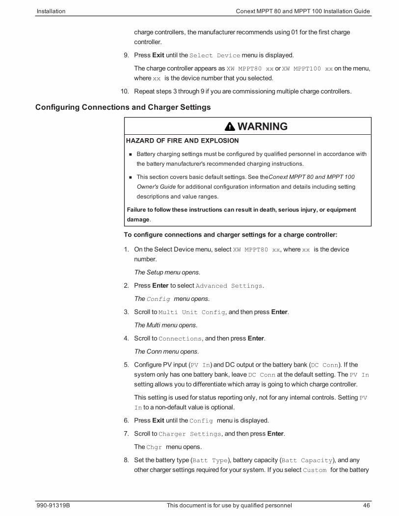
charge controllers, themanufacturer recommends using 01 for the first chargecontroller.
9. Press Exit until the Select Devicemenu is displayed.
The charge controller appears as XW MPPT80 xx or XW MPPT100 xx on themenu,where xx is the device number that you selected.
10. Repeat steps 3 through 9 if you are commissioningmultiple charge controllers.
Configuring Connections and Charger Settings
WARNINGHAZARD OF FIRE AND EXPLOSION
n Battery charging settings must be configured by qualified personnel in accordance withthe battery manufacturer's recommended charging instructions.
n This section covers basic default settings. See theConext MPPT 80 and MPPT 100Owner's Guide for additional configuration information and details including settingdescriptions and value ranges.
Failure to follow these instructions can result in death, serious injury, or equipmentdamage.
To configure connections and charger settings for a charge controller:
1. On the Select Devicemenu, select XW MPPT80 xx, where xx is the devicenumber.
The Setupmenu opens.
2. Press Enter to select Advanced Settings.
The Config menu opens.
3. Scroll to Multi Unit Config, and then press Enter.
TheMulti menu opens.
4. Scroll to Connections, and then press Enter.
The Connmenu opens.
5. Configure PV input (PV In) and DC output or the battery bank (DC Conn). If thesystem only has one battery bank, leave DC Conn at the default setting. The PV In
setting allows you to differentiate which array is going to which charge controller.
This setting is used for status reporting only, not for any internal controls. Setting PVIn to a non-default value is optional.
6. Press Exit until the Config menu is displayed.
7. Scroll to Charger Settings, and then press Enter.
The Chgr menu opens.
8. Set the battery type (Batt Type), battery capacity (Batt Capacity), and anyother charger settings required for your system. If you select Custom for the battery
Installation Conext MPPT 80 and MPPT 100 Installation Guide
990-91319B This document is for use by qualified personnel 46

type, you can further configure bulk, absorption, float, and other settings for thecharge cycle in the Custom Settingsmenu that appears.
9. While in the Chgr menu, make sure the nominal battery voltage (Batt Voltage)is set correctly. The default value is 48 V. If your system is a 24 V battery system,then change it to 24 V.
10. Press Exit until the Select Devicemenu is displayed.
Copying Settings to Another Charge Controller
WARNINGHAZARD OF FIRE AND EXPLOSION
n Do not copy settings from one charge controller to another unless the battery banks areidentical: same size, type, and so on.
n See theConext MPPT 80 and MPPT 100 Owner's Guide for additional configurationinformation and details including setting descriptions and value ranges.
Failure to follow these instructions can result in death, serious injury, or equipmentdamage.
Settings that are copied from one charge controller to another are:
n Batt Type
n Batt Capacity
n Max Chg Rate
n Charge Cycle
n ReCharge Volts
n Absorb Time
n Default Batt Temp
n Batt Voltage
n DC Conn
n Custom battery settings (if Custom battery type selected) including EqlzSupport, Eqlz Voltage, Bulk Voltage, Absorb Voltage, Float
Voltage, and BattTempComp.
If you are commissioningmultiple charge controllers, follow these steps to copy thesettings from the configured charge controller to the other charge controllers:
1. On the Select Devicemenu, select the next charge controller for configuration.
The Setup menu opens.
2. Press Enter to select Advanced Settings.
The Config menu opens.
3. Scroll to Copy from, and then press Enter to select the charge controller from
Conext MPPT 80 and MPPT 100 Installation Guide Installation
47 This document is for use by qualified personnel 990-91319B
which you want to copy. Scroll to select the charge controller with the device numberthat matches the first charge controller you configured, and then press Enter again.
The settings are automatically copied from the selected charge controller.
NOTE: The Copy from commandwill not give you any indication that it hascompleted its task. To check that the charger settings have been copied properly,view some of the settings you originally configured.
4. Repeat steps 1 to 3 for the remaining charge controllers.
5. After you have finished configuring, press theEnter, up arrow, and down arrowbuttons simultaneously to hide the Advanced Settingsmenu item.
Starting the Charge ControllerTo start the charge controller:
1. Turn on the charge controller battery breaker.
2. Close the PV array disconnect switch.
If the PV array voltage exceeds theminimum start voltage, the charge controller beginscharging and theOn/Charging LED starts flashing.
If the PV array voltage is not above the start voltage, the charge controller is powered butnot charging. TheOn/Charging LED stays solid green.
Shutting off the Charge ControllerTo shut off the charge controller:
1. Open the PV array disconnect switch.
2. Turn off the charge controller battery breaker.
Installation Conext MPPT 80 and MPPT 100 Installation Guide
990-91319B This document is for use by qualified personnel 48


Troubleshooting
Troubleshooting Conext MPPT 80 and MPPT 100 Installation Guide
3
Troubleshooting 51
Replacing the Ground Fault Protection Fuse 53
Ground Faults in a Normally Ungrounded Array 53
What's in This Chapter?
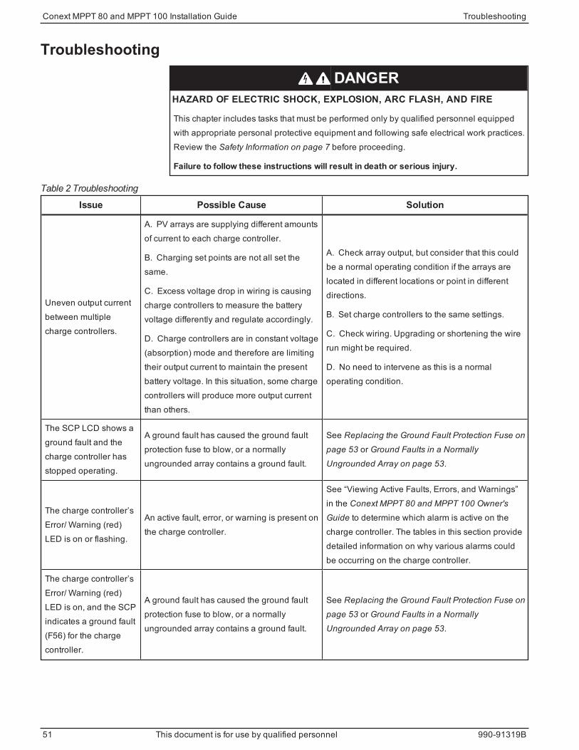
Troubleshooting
DANGERHAZARD OF ELECTRIC SHOCK, EXPLOSION, ARC FLASH, AND FIRE
This chapter includes tasks that must be performed only by qualified personnel equippedwith appropriate personal protective equipment and following safe electrical work practices.Review the Safety Information on page 7 before proceeding.
Failure to follow these instructions will result in death or serious injury.
Issue Possible Cause Solution
Uneven output currentbetween multiplecharge controllers.
A. PV arrays are supplying different amountsof current to each charge controller.
B. Charging set points are not all set thesame.
C. Excess voltage drop in wiring is causingcharge controllers to measure the batteryvoltage differently and regulate accordingly.
D. Charge controllers are in constant voltage(absorption) mode and therefore are limitingtheir output current to maintain the presentbattery voltage. In this situation, some chargecontrollers will produce more output currentthan others.
A. Check array output, but consider that this couldbe a normal operating condition if the arrays arelocated in different locations or point in differentdirections.
B. Set charge controllers to the same settings.
C. Check wiring. Upgrading or shortening the wirerun might be required.
D. No need to intervene as this is a normaloperating condition.
The SCP LCD shows aground fault and thecharge controller hasstopped operating.
A ground fault has caused the ground faultprotection fuse to blow, or a normallyungrounded array contains a ground fault.
See Replacing the Ground Fault Protection Fuse onpage 53 or Ground Faults in a NormallyUngrounded Array on page 53.
The charge controller’sError/ Warning (red)LED is on or flashing.
An active fault, error, or warning is present onthe charge controller.
See “Viewing Active Faults, Errors, and Warnings”in the Conext MPPT 80 and MPPT 100 Owner'sGuide to determine which alarm is active on thecharge controller. The tables in this section providedetailed information on why various alarms couldbe occurring on the charge controller.
The charge controller’sError/ Warning (red)LED is on, and the SCPindicates a ground fault(F56) for the chargecontroller.
A ground fault has caused the ground faultprotection fuse to blow, or a normallyungrounded array contains a ground fault.
See Replacing the Ground Fault Protection Fuse onpage 53 or Ground Faults in a NormallyUngrounded Array on page 53.
Table 2 Troubleshooting
Conext MPPT 80 and MPPT 100 Installation Guide Troubleshooting
51 This document is for use by qualified personnel 990-91319B
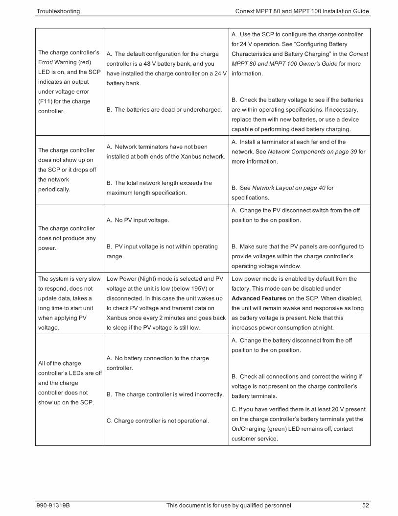
The charge controller’sError/ Warning (red)LED is on, and the SCPindicates an outputunder voltage error(F11) for the chargecontroller.
A. The default configuration for the chargecontroller is a 48 V battery bank, and youhave installed the charge controller on a 24 Vbattery bank.
B. The batteries are dead or undercharged.
A. Use the SCP to configure the charge controllerfor 24 V operation. See “Configuring BatteryCharacteristics and Battery Charging” in the ConextMPPT 80 and MPPT 100 Owner's Guide for moreinformation.
B. Check the battery voltage to see if the batteriesare within operating specifications. If necessary,replace them with new batteries, or use a devicecapable of performing dead battery charging.
The charge controllerdoes not show up onthe SCP or it drops offthe networkperiodically.
A. Network terminators have not beeninstalled at both ends of the Xanbus network.
B. The total network length exceeds themaximum length specification.
A. Install a terminator at each far end of thenetwork. See Network Components on page 39 formore information.
B. See Network Layout on page 40 forspecifications.
The charge controllerdoes not produce anypower.
A. No PV input voltage.
B. PV input voltage is not within operatingrange.
A. Change the PV disconnect switch from the offposition to the on position.
B. Make sure that the PV panels are configured toprovide voltages within the charge controller’soperating voltage window.
The system is very slowto respond, does notupdate data, takes along time to start unitwhen applying PVvoltage.
Low Power (Night) mode is selected and PVvoltage at the unit is low (below 195V) ordisconnected. In this case the unit wakes upto check PV voltage and transmit data onXanbus once every 2 minutes and goes backto sleep if the PV voltage is still low.
Low power mode is enabled by default from thefactory. This mode can be disabled underAdvanced Features on the SCP. When disabled,the unit will remain awake and responsive as longas battery voltage is present. Note that thisincreases power consumption at night.
All of the chargecontroller’s LEDs are offand the chargecontroller does notshow up on the SCP.
A. No battery connection to the chargecontroller.
B. The charge controller is wired incorrectly.
C. Charge controller is not operational.
A. Change the battery disconnect from the offposition to the on position.
B. Check all connections and correct the wiring ifvoltage is not present on the charge controller’sbattery terminals.
C. If you have verified there is at least 20 V presenton the charge controller’s battery terminals yet theOn/Charging (green) LED remains off, contactcustomer service.
Troubleshooting Conext MPPT 80 and MPPT 100 Installation Guide
990-91319B This document is for use by qualified personnel 52
The charge controller’sOn/Charging (green)LED is flashing.
The charge controller is outputting chargecurrent.
No problem. This is intended operation. See“Viewing Status Information on the Solar ChargeController” in the Conext MPPT 80 and MPPT 100Owner's Guide for LED status information.
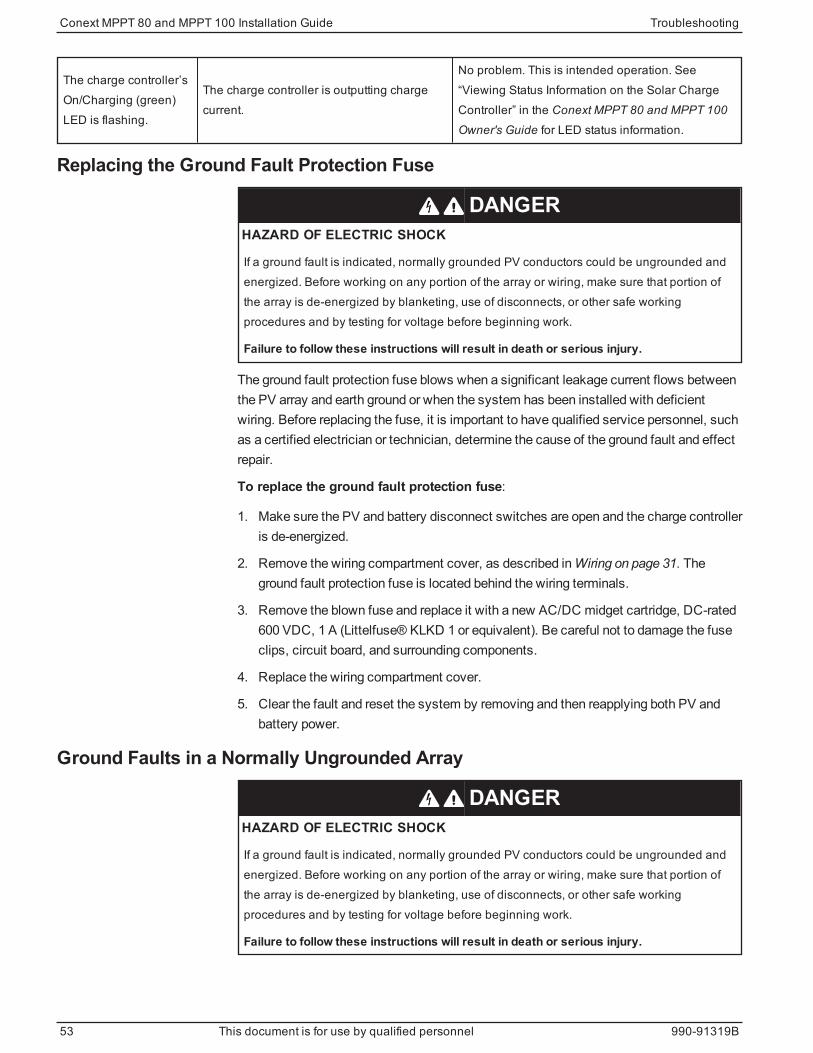
Replacing the Ground Fault Protection Fuse
DANGERHAZARD OF ELECTRIC SHOCK
If a ground fault is indicated, normally grounded PV conductors could be ungrounded andenergized. Before working on any portion of the array or wiring, make sure that portion ofthe array is de-energized by blanketing, use of disconnects, or other safe workingprocedures and by testing for voltage before beginning work.
Failure to follow these instructions will result in death or serious injury.
The ground fault protection fuse blows when a significant leakage current flows betweenthe PV array and earth ground or when the system has been installed with deficientwiring. Before replacing the fuse, it is important to have qualified service personnel, suchas a certified electrician or technician, determine the cause of the ground fault and effectrepair.
To replace the ground fault protection fuse:
1. Make sure the PV and battery disconnect switches are open and the charge controlleris de-energized.
2. Remove the wiring compartment cover, as described inWiring on page 31. Theground fault protection fuse is located behind the wiring terminals.
3. Remove the blown fuse and replace it with a new AC/DC midget cartridge, DC-rated600 VDC, 1 A (Littelfuse® KLKD 1 or equivalent). Be careful not to damage the fuseclips, circuit board, and surrounding components.
4. Replace the wiring compartment cover.
5. Clear the fault and reset the system by removing and then reapplying both PV andbattery power.
Ground Faults in a Normally Ungrounded Array
DANGERHAZARD OF ELECTRIC SHOCK
If a ground fault is indicated, normally grounded PV conductors could be ungrounded andenergized. Before working on any portion of the array or wiring, make sure that portion ofthe array is de-energized by blanketing, use of disconnects, or other safe workingprocedures and by testing for voltage before beginning work.
Failure to follow these instructions will result in death or serious injury.
Conext MPPT 80 and MPPT 100 Installation Guide Troubleshooting
53 This document is for use by qualified personnel 990-91319B
On a normally ungrounded (floating) array, the ground fault protection system indicates afault when a short circuit or lower than normal resistance exists between the array andground. Before resetting the fault and attempting to restart the system, it is important tohave qualified service personnel, such as a certified electrician or technician, determinethe cause of the ground fault and effect repair.
To mitigate a ground fault in a normally ungrounded array:
1. Verify that the PV and battery disconnect switches are open and the charge controlleris de-energized.
2. Search or troubleshoot for a ground fault on the PV array (for example, a broken PVpanel or pinched PV wire).
3. Clear the fault and reset the system by removing and then reapplying both PV andbattery power.
Troubleshooting Conext MPPT 80 and MPPT 100 Installation Guide
990-91319B This document is for use by qualified personnel 54

Specifications
Specifications Conext MPPT 80 and MPPT 100 Installation Guide
A
Electrical Specifications 57
MPPT Voltage Range 58
Operating Below the PV Array Voltage Full Power Range 59
Conext MPPT 80 600 59
Conext MPPT 100 600 59
Default Battery Charging Settings 60
Mechanical Specifications 61
Output Power Versus Ambient Temperature 62
Accessories 63
Conext System Control Panel 63
Conext Gateway 63
Conext Config Tool 63
Regulatory Approvals 64
What's in This Chapter?

Electrical SpecificationsNote: All specifications are subject to change without notice.
Specification Conext MPPT 80 600 Conext MPPT 100 600
Maximum PV Array Open Circuit Voltage 600 VDC
PV Array Voltage Operating Range 195 to 550 VDC
PV Array Voltage Full Power Range1 230 to 550 VDC
Maximum Power Point Tracking Range 195 to 510 VDC
PV Input Start Voltage 230 VDC2
Maximum Operating Current 23 A 29 A
Maximum Permissible Array Short Circuit Current atSTC
28 A 35 A
Nominal Battery Voltages 24 and 48 VDC (Default is 48 V)
Battery Voltage Operating Range 16 to 67 VDC
Maximum Charging Current 80 A 100 A
Maximum Charging Power
(at 30 V, nominal 24 V battery bank)
(at 60 V, nominal 48 V battery bank)
2400 W
4800 W
3000 W
6000 W
Maximum Power Conversion Efficiency
(nominal 24 V battery bank)
(nominal 48 V battery bank)
92%
95%
Auxiliary Output Dry contact switching up to 60 VDC, 30 VAC, 8 A
Charger Regulation Method
Three stage (bulk, absorption, float)
Two stage (bulk, absorption)
Manual equalization
Tare Losses3Less than 1.0 W (Xanbus power supply on)
Less than 0.5 W (Xanbus power supply off)
Table 3 Electrical specifications
1Full power output below 230 V is not assured. See Operating Below the PVArrayVoltage Full Power
Range on page 59 for more information.2Charging does not begin until input voltage exceeds 230 V. Once charging has started, it will
continue until the input voltage falls below 195 V.3These values are based on the following specifications: a) The battery voltage is 48 V, and
b) "Lo Pwr at Night" enabled. See "Reducing Tare Loss" in the Conext MPPT 80 and MPPT 100
Owner's Guide for more information.
Conext MPPT 80 and MPPT 100 Installation Guide Specifications
57 This document is for use by qualified personnel 990-91319B

Note:
n PV array voltages often exceed STC voltage specifications, especially when thearray is cold. At cold temperatures the open circuit voltage will be higher than at STCorMPPT operating points. Refer to data provided by themaker of the PV panels andensure themaximum voltage can never exceed the limits in the table above.
n PV array current might exceed STC current specifications, especially under intensesunlight, certain atmospheric conditions, or from reflections (i.e, water, snow, or ice).Some electrical codes (eg. the NEC) consider the worst case current to be 25%higher than the short circuit current at STC. For selection of wire and somecomponents (breakers, fuses) a further 25% derating is applied.
MPPT Voltage RangeThe charge controller’s Maximum Power Point Tracking (MPPT) algorithmmaximizesthe output energy of PV arrays as long as the operating voltage is within theMPPToperational window. TheMPPT operational window is shown below.
NOTICEEQUIPMENT DAMAGE
Make sure that the PV arrays have been designed to always operate within the MPPToperational window (0 to 600 V).
Failure to follow these instructions can result in equipment damage.
Figure 17 MPPT Operational Window
Specifications Conext MPPT 80 and MPPT 100 Installation Guide
990-91319B This document is for use by qualified personnel 58
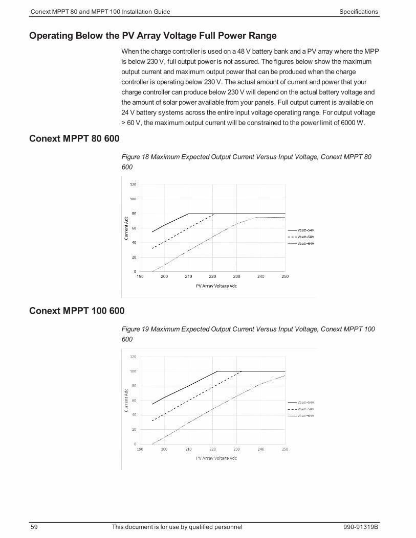
Operating Below the PV Array Voltage Full Power RangeWhen the charge controller is used on a 48 V battery bank and a PV array where theMPPis below 230 V, full output power is not assured. The figures below show themaximumoutput current andmaximum output power that can be produced when the chargecontroller is operating below 230 V. The actual amount of current and power that yourcharge controller can produce below 230 V will depend on the actual battery voltage andthe amount of solar power available from your panels. Full output current is available on24 V battery systems across the entire input voltage operating range. For output voltage> 60 V, themaximum output current will be constrained to the power limit of 6000W.
Conext MPPT 80 600
Figure 18 Maximum Expected Output Current Versus Input Voltage, Conext MPPT 80600
Conext MPPT 100 600
Figure 19 Maximum Expected Output Current Versus Input Voltage, Conext MPPT 100600
Conext MPPT 80 and MPPT 100 Installation Guide Specifications
59 This document is for use by qualified personnel 990-91319B

Default Battery Charging SettingsAll settings in the following table are based on a 48 V nominal battery bank at 25°C(77°F). For a 24 V nominal battery bank, divide the voltage values in this table by two.
SettingBattery Type
Flooded1 Gel AGM
Equalize Voltage 64.0 V n/a n/a
ReCharge Voltage 50.0 V 50.0 V 50.0 V
Bulk Voltage 57.6 V 56.8 V 57.2 V
Absorption Voltage 57.6 V 56.8 V 57.2 V
Float Voltage 54.0 V 55.2 V 53.6 V
Absorption Time 180 min 180 min 180 min
Batt Temp Comp -108 mV/C -108 mV/C -84 mV/C
1When Custom is selected for the battery type, the default settings are based on the flooded
battery type.
Specifications Conext MPPT 80 and MPPT 100 Installation Guide
990-91319B This document is for use by qualified personnel 60
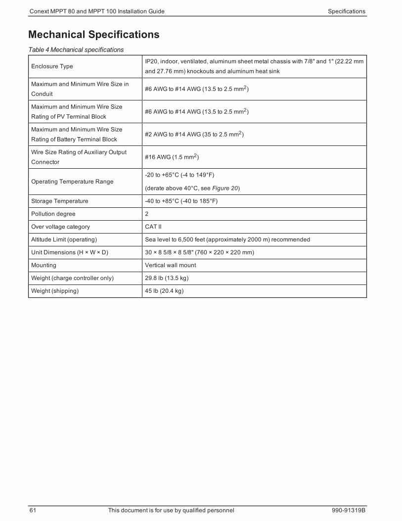
Mechanical Specifications
Enclosure TypeIP20, indoor, ventilated, aluminum sheet metal chassis with 7/8" and 1" (22.22 mmand 27.76 mm) knockouts and aluminum heat sink
Maximum and Minimum Wire Size inConduit
#6 AWG to #14 AWG (13.5 to 2.5 mm2)
Maximum and Minimum Wire SizeRating of PV Terminal Block
#6 AWG to #14 AWG (13.5 to 2.5 mm2)
Maximum and Minimum Wire SizeRating of Battery Terminal Block
#2 AWG to #14 AWG (35 to 2.5 mm2)
Wire Size Rating of Auxiliary OutputConnector
#16 AWG (1.5 mm2)
Operating Temperature Range-20 to +65°C (-4 to 149°F)
(derate above 40°C, see Figure 20)
Storage Temperature -40 to +85°C (-40 to 185°F)
Pollution degree 2
Over voltage category CAT II
Altitude Limit (operating) Sea level to 6,500 feet (approximately 2000 m) recommended
Unit Dimensions (H × W × D) 30 × 8 5/8 × 8 5/8" (760 × 220 × 220 mm)
Mounting Vertical wall mount
Weight (charge controller only) 29.8 lb (13.5 kg)
Weight (shipping) 45 lb (20.4 kg)
Table 4 Mechanical specifications
Conext MPPT 80 and MPPT 100 Installation Guide Specifications
61 This document is for use by qualified personnel 990-91319B

Output Power Versus Ambient TemperatureOnce the charge controller’s heat sink reaches maximum full-power operatingtemperature, the charge controller reduces its power output to ensure component ratingsare not exceeded.
Figure 20 Output power vs. ambient temperature, Conext MPPT 80 600
0
1000
2000
3000
4000
5000
6000
7000
-20 0 20 40 60 80
ma
x P
ow
er
)W)
Ambient Temp (°C)
Thermal Dera!ng for MPPT 80-600
Figure 21 Output power vs. ambient temperature, Conext MPPT 100 600
0
1000
2000
3000
4000
5000
6000
7000
-20 0 20 40 60 80
ma
x P
ow
er
)W)
Ambient Temp (°C)
Thermal Dera!ng for MPPT 100-600
Specifications Conext MPPT 80 and MPPT 100 Installation Guide
990-91319B This document is for use by qualified personnel 62
AccessoriesConext System Control Panel
The Conext System Control Panel (SCP) (Part Number 865-1050) is required forinstallation of the charge controller and is strongly recommended for ongoing operation.
As the primary interface to the charge controller, the SCP is used for setup andconfiguration. Once installation is complete, you can use the SCP for monitoring andfault reporting. Only one SCP is required tomonitor multiple charge controllers.
Note: Youmust use the SCP with firmware version 1.05.00 or higher for full compatibilitywith the charge controller. For information on updating your firmware, contact customerservice. The Conext Config Tool or Conext Gateway is required for upgrading.
Conext GatewayIn place of the SCP, the Conext Gateway (Part Number 865-0329) can also be used. TheConext Gateway allows you to configure andmonitor the charge controller through a webinterface on a PC or laptop. See theConext Gateway Owner's Guide (975-0806-01-xx).
Conext Config ToolThe Conext Config Tool (Part Number 865-1155) is a commissioning tool used forconfiguring or upgrading a Conext system.
Conext MPPT 80 and MPPT 100 Installation Guide Specifications
63 This document is for use by qualified personnel 990-91319B

Regulatory ApprovalsCertified to UL 1741 and to CSA 107.1 and carries the c(CSA)us mark. EMC -North America:
n FCC Part-15 sub part B, Class B, emission limits
n Industry Canada ICES-003, Class B, emission limits
CE Marked and complies with the following:
Low Voltage Directive 2014/35/EU, per:
n EN/IEC 62109-1: safety of power converters used in photovoltaic systems
EMC Directive 2014/30/EU, per:
n EN61000-6-3 Emission standard for residential, commercial, and light- industrialenvironments
n EN61000-6-1 Immunity for residential, commercial, and light-industrial environments
Australia:
n RCMmark
Specifications Conext MPPT 80 and MPPT 100 Installation Guide
990-91319B This document is for use by qualified personnel 64


Schneider Electric
Asstandards, specifications, and designs change from time to time,
please ask for confirmation of the information given in this publication.
For other country details please contact your localSchneider Electric
SalesRepresentative or visit the Schneider ElectricSolar Business
website at: http://solar.schneider-electric.com/
© 2019 Schneider Electric. All RightsReserved.
990-91319B Printed in: India
barcode