Conettix Ethernet Communication Moduleresource.boschsecurity.com/documents/B426_Installation... ·...
34
Conettix Ethernet Communication Module B426 en Installation and Operation Guide (UL)
Transcript of Conettix Ethernet Communication Moduleresource.boschsecurity.com/documents/B426_Installation... ·...

Conettix Ethernet Communication ModuleB426
en Installation and Operation Guide (UL)

Table of contents
1 Safety 42 Introduction 52.1 About documentation 52.2 Bosch Security Systems, Inc. product manufacturing dates 5
3 System overview 63.1 Overview 83.2 Bus address settings 8
4 Installation 104.1 Mount the module in the enclosure 104.2 Mount and wire the tamper switch (optional) 104.3 Wire to the control panel 10
5 Configuration 135.1 Configure for SDI2 control panels 135.2 Configure for SDI or option bus control panels 135.2.1 Plug and Play configuration 135.2.2 Web-based configuration 135.3 Determine a module's hostname or IP address 145.3.1 Determine a module’s hostname 145.3.2 Use an SDI/SDI2 keypad or RPS to discover the IP address of a module 145.3.3 Use DHCP to look up the IP address of a network-connected module 145.3.4 Use AutoIP with a directly connected module 145.4 Use web-based configuration menus 165.5 Device Information (home) page 165.6 Change and save settings using the web 175.7 Basic Network Settings page 175.8 Advanced Network Settings page 205.9 Panel Address Settings page 215.10 Encryption and Security Settings page 225.11 Maintenance page 235.12 Factory Default page 255.13 Firmware Update page 255.14 Exiting the web-based configuration pages 26
6 Maintenance and troubleshooting LEDs 276.1 Show the firmware version 28
7 Specifications and certifications 297.1 Technical specifications 297.2 Certifications 30
Conettix Ethernet CommunicationModule
Table of Contents | en 3
Bosch Security Systems, Inc. Installation and Operation Guide (UL) 2013.08 | 02 | F.01U.281.208
SafetyESD Precaution
Please note that the B426 board comes without any case/box and all components are exposedfor finger touches - therefore extra attention must be paid to ESD (electrostatic discharge)precaution. Make sure there is no static interference when using the board. Appropriate ESDprotections must be taken and wearing electrostatic equipment is recommended, such as anti-static wrist strap.ESD damage can range from subtle performance degradation to complete device failure.Precision integrated circuits may be more susceptible to damage because very smallparametric changes could cause the device not to meet its published specifications.
!
Warning!
Failure to follow these instructions can result in a failure to initiate alarm conditions. Bosch
Security Systems, Inc. is not responsible for improperly installed, tested, or maintained
devices. Follow these instructions to avoid personal injury and damage to the equipment.
Notice!
Inform the operator and the local authority having jurisdiction (AHJ) before installing the
module in an existing system.
Disconnect all power to the control panel before installing the module.
Before installing a B426, refer to Technical specifications, page 29.
1
4 en | SafetyConettix Ethernet Communication
Module
2013.08 | 02 | F.01U.281.208 Installation and Operation Guide (UL) Bosch Security Systems, Inc.

Introduction
About documentationCopyrightThis document is the intellectual property of Bosch Security Systems, Inc. and is protected bycopyright. All rights reserved.
TrademarksAll hardware and software product names used in this document are likely to be registeredtrademarks and must be treated accordingly.
Bosch Security Systems, Inc. product manufacturing datesUse the serial number located on the product label and refer to the Bosch Security Systems,Inc. web site at http://www.boschsecurity.com/datecodes/.The following image shows an example of a product label and highlights where to find themanufacturing date within the serial number.
2
2.1
2.2
Conettix Ethernet CommunicationModule
Introduction | en 5
Bosch Security Systems, Inc. Installation and Operation Guide (UL) 2013.08 | 02 | F.01U.281.208

System overview
!
Warning!
Failure to follow these instructions can result in a failure to initiate alarm conditions. Bosch
Security Systems, Inc. is not responsible for improperly installed, tested, or maintained
devices. Follow these instructions to avoid personal injury and damage to the equipment.
Notice!
Inform the operator and the local authority having jurisdiction (AHJ) before installing the
module in an existing system.
Disconnect all power to the control panel before installing the module.
Before installing a B426, refer to Technical specifications, page 29.
Use the B426 for bi-directional communication over an Ethernet network.
1
4
5
6
3
2
7
8
9
10
12
13
11
Figure 3.1: B426 system connections overview
3
6 en | System overviewConettix Ethernet Communication
Module
2013.08 | 02 | F.01U.281.208 Installation and Operation Guide (UL) Bosch Security Systems, Inc.
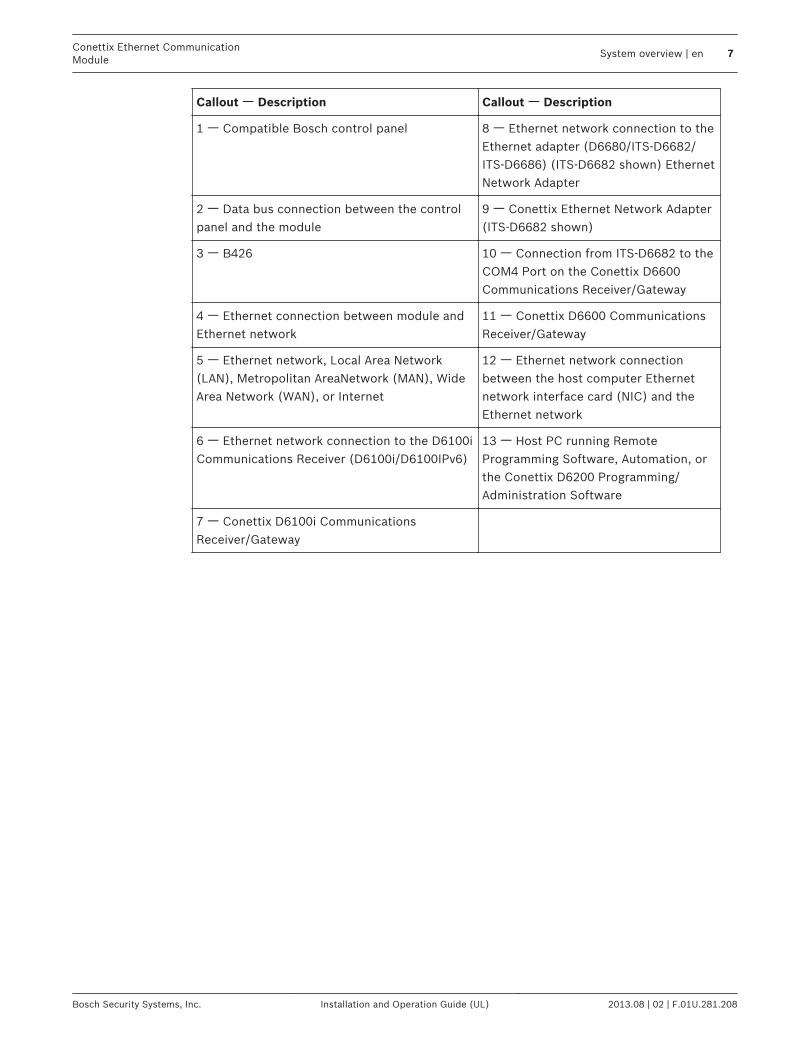
Callout ᅳ Description Callout ᅳ Description
1 ᅳ Compatible Bosch control panel 8 ᅳ Ethernet network connection to theEthernet adapter (D6680/ITS-D6682/ITS-D6686) (ITS-D6682 shown) EthernetNetwork Adapter
2 ᅳ Data bus connection between the controlpanel and the module
9 ᅳ Conettix Ethernet Network Adapter(ITS-D6682 shown)
3 ᅳ B426 10 ᅳ Connection from ITS-D6682 to theCOM4 Port on the Conettix D6600Communications Receiver/Gateway
4 ᅳ Ethernet connection between module andEthernet network
11 ᅳ Conettix D6600 CommunicationsReceiver/Gateway
5 ᅳ Ethernet network, Local Area Network(LAN), Metropolitan AreaNetwork (MAN), WideArea Network (WAN), or Internet
12 ᅳ Ethernet network connectionbetween the host computer Ethernetnetwork interface card (NIC) and theEthernet network
6 ᅳ Ethernet network connection to the D6100iCommunications Receiver (D6100i/D6100IPv6)
13 ᅳ Host PC running RemoteProgramming Software, Automation, orthe Conettix D6200 Programming/Administration Software
7 ᅳ Conettix D6100i CommunicationsReceiver/Gateway
Conettix Ethernet CommunicationModule
System overview | en 7
Bosch Security Systems, Inc. Installation and Operation Guide (UL) 2013.08 | 02 | F.01U.281.208
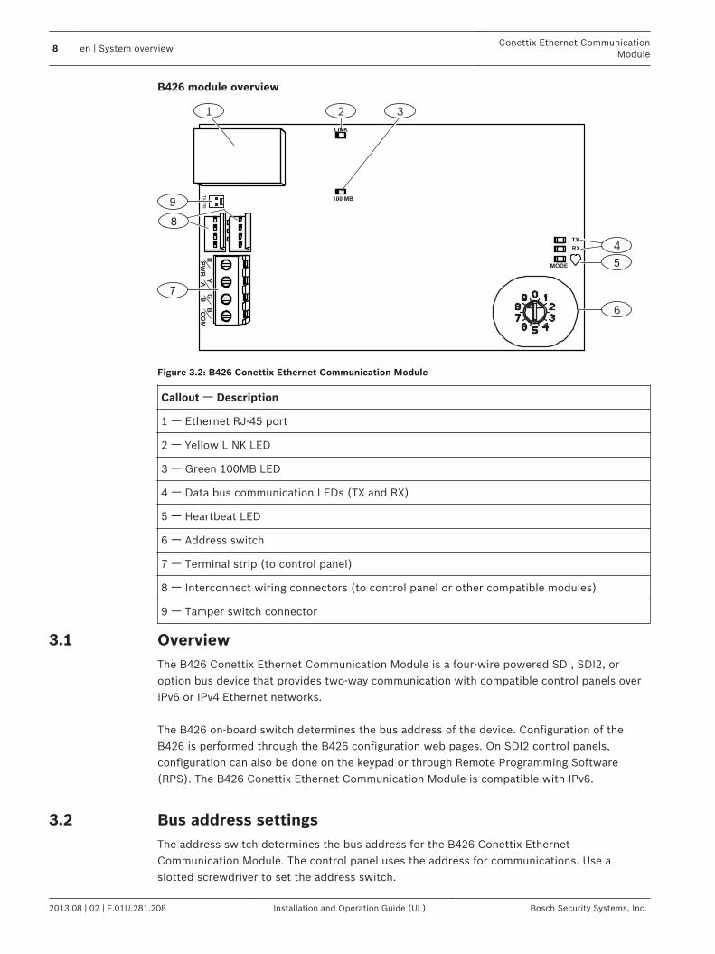
B426 module overview
1
4
5
7
9
6
TX
RX
R PW
R
G B
Y A
B CO
M
MODE
8
TMPR
3
LINK
100 MB
2
Figure 3.2: B426 Conettix Ethernet Communication Module
Callout ᅳ Description
1 ᅳ Ethernet RJ-45 port
2 ᅳ Yellow LINK LED
3 ᅳ Green 100MB LED
4 ᅳ Data bus communication LEDs (TX and RX)
5 ᅳ Heartbeat LED
6 ᅳ Address switch
7 ᅳ Terminal strip (to control panel)
8 ᅳ Interconnect wiring connectors (to control panel or other compatible modules)
9 ᅳ Tamper switch connector
OverviewThe B426 Conettix Ethernet Communication Module is a four-wire powered SDI, SDI2, oroption bus device that provides two-way communication with compatible control panels overIPv6 or IPv4 Ethernet networks. The B426 on-board switch determines the bus address of the device. Configuration of theB426 is performed through the B426 configuration web pages. On SDI2 control panels,configuration can also be done on the keypad or through Remote Programming Software(RPS). The B426 Conettix Ethernet Communication Module is compatible with IPv6.
Bus address settingsThe address switch determines the bus address for the B426 Conettix EthernetCommunication Module. The control panel uses the address for communications. Use aslotted screwdriver to set the address switch.
3.1
3.2
8 en | System overviewConettix Ethernet Communication
Module
2013.08 | 02 | F.01U.281.208 Installation and Operation Guide (UL) Bosch Security Systems, Inc.

Notice!
The module reads the address switch setting only during power up. If you change the
switches after you apply power to the module, you must cycle the power to the module in
order for the new setting to be enabled.
The B426 address switch provides the value for the module's address. The figure below showsthe address switch setting for address 1. Refer to the table below for panel-specific settings.
Figure 3.3: Address switch set to address 1
Control panels Switchposition
B426 address Bus type Function
Web-based configurationsetting
0 Configurable Any Web-based configuration
GV4 Series, B5512/B4512/B3512
1 1 SDI2 Automation, RPS, or Reporting
GV4 Series 2 2 SDI2 Automation, RPS, or Reporting
GV4 Series, GV3 Series, GV2Series, G Series v6.3 orhigher
3 80 SDI Automation
GV4 Series, GV3 Series, GV2Series, G Series v6.3 orhigher
4 88 SDI Reporting or RPS
GV4 Series, GV3 Series 5 92 SDI Reporting or RPS
DS7240V2, DS7220V2, EasySeries V3+, AMAX 2000
6 134 Option Remote programming, Reporting
DS7400Xi 7 13 Option Remote programming, Reporting
DS7400Xi
8 14 Option Reporting
FPD-7024 9 250 Option Remote programming, Reporting
Table 3.1: B426 address switch settings
Notice!
You can use web browser configuration of the module's bus address setting only when the
switch is in the ’0’ position.
Conettix Ethernet CommunicationModule
System overview | en 9
Bosch Security Systems, Inc. Installation and Operation Guide (UL) 2013.08 | 02 | F.01U.281.208
InstallationAfter you set the address switch for the proper address, install the module in the enclosureand then wire the module to the control panel and to the Ethernet connection.
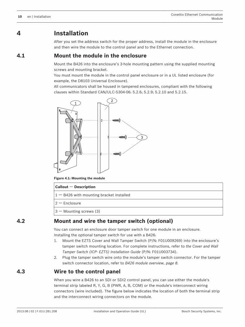
Mount the module in the enclosureMount the B426 into the enclosure’s 3-hole mounting pattern using the supplied mountingscrews and mounting bracket.You must mount the module in the control panel enclosure or in a UL listed enclosure (forexample, the D8103 Universal Enclosure).All communicators shall be housed in tampered enclosures, compliant with the followingclauses within Standard CAN/ULC-S304-06: 5.2.6; 5.2.9; 5.2.10 and 5.2.15.
3
12
Figure 4.1: Mounting the module
Callout ᅳ Description
1 ᅳ B426 with mounting bracket installed
2 ᅳ Enclosure
3 ᅳ Mounting screws (3)
Mount and wire the tamper switch (optional)You can connect an enclosure door tamper switch for one module in an enclosure.Installing the optional tamper switch for use with a B426:1. Mount the EZTS Cover and Wall Tamper Switch (P/N: F01U009269) into the enclosure’s
tamper switch mounting location. For complete instructions, refer to the Cover and WallTamper Switch (ICP- EZTS) Installation Guide (P/N: F01U003734).
2. Plug the tamper switch wire onto the module’s tamper switch connector. For the tamperswitch connector location, refer to B426 module overview, page 8.
Wire to the control panelWhen you wire a B426 to an SDI or SDI2 control panel, you can use either the module'sterminal strip labeled R, Y, G, B (PWR, A, B, COM) or the module's interconnect wiringconnectors (wire included). The figure below indicates the location of both the terminal stripand the interconnect wiring connectors on the module.
4
4.1
4.2
4.3
10 en | InstallationConettix Ethernet Communication
Module
2013.08 | 02 | F.01U.281.208 Installation and Operation Guide (UL) Bosch Security Systems, Inc.

Notice!
Remove all power (AC and Battery) before making any connections. Failure to do so may
result in personal injury and/or equipment damage.
Notice!
Use either the terminal strip wiring or interconnect cable to wire to the control panel. Do not
use both. When connecting multiple modules, you can combine terminal strip and
interconnect wiring connectors in series.
Run the wiring connections from the module to the data bus terminals on the compatiblecontrol panel. Connect the Ethernet cable to the Ethernet port on the module.
Figure 4.2: Using terminal strip or interconnect cable wiring (GV4 Series control panel shown)
Callout ᅳ Description
1 ᅳ SDI2 control panel. For SDI control panels, wire R, Y, G, B to the SDI bus.
2 ᅳ Module
3 ᅳ To Ethernet network
4 ᅳ Terminal strip wiring
5 ᅳ Interconnect cable (P/N: F01U079745) (included)
Conettix Ethernet CommunicationModule
Installation | en 11
Bosch Security Systems, Inc. Installation and Operation Guide (UL) 2013.08 | 02 | F.01U.281.208
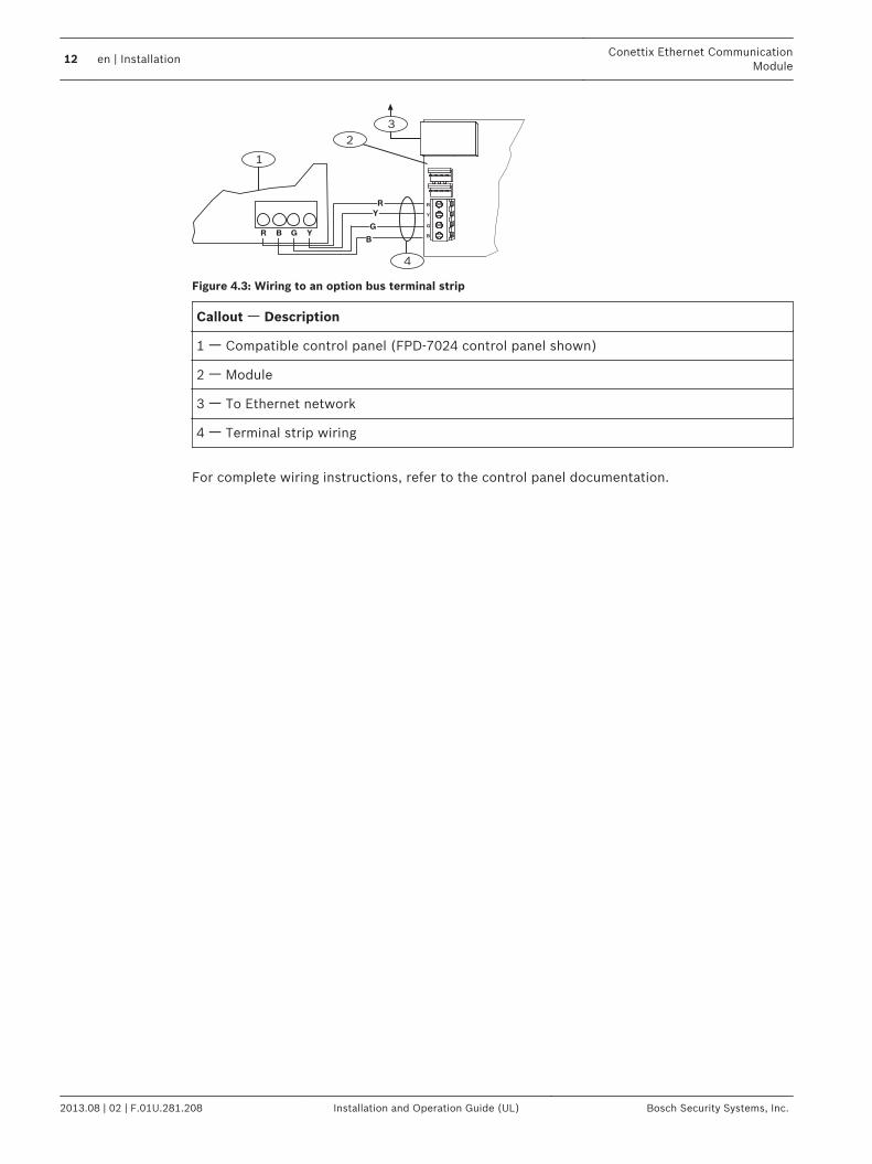
Figure 4.3: Wiring to an option bus terminal strip
Callout ᅳ Description
1 ᅳ Compatible control panel (FPD-7024 control panel shown)
2 ᅳ Module
3 ᅳ To Ethernet network
4 ᅳ Terminal strip wiring
For complete wiring instructions, refer to the control panel documentation.
12 en | InstallationConettix Ethernet Communication
Module
2013.08 | 02 | F.01U.281.208 Installation and Operation Guide (UL) Bosch Security Systems, Inc.
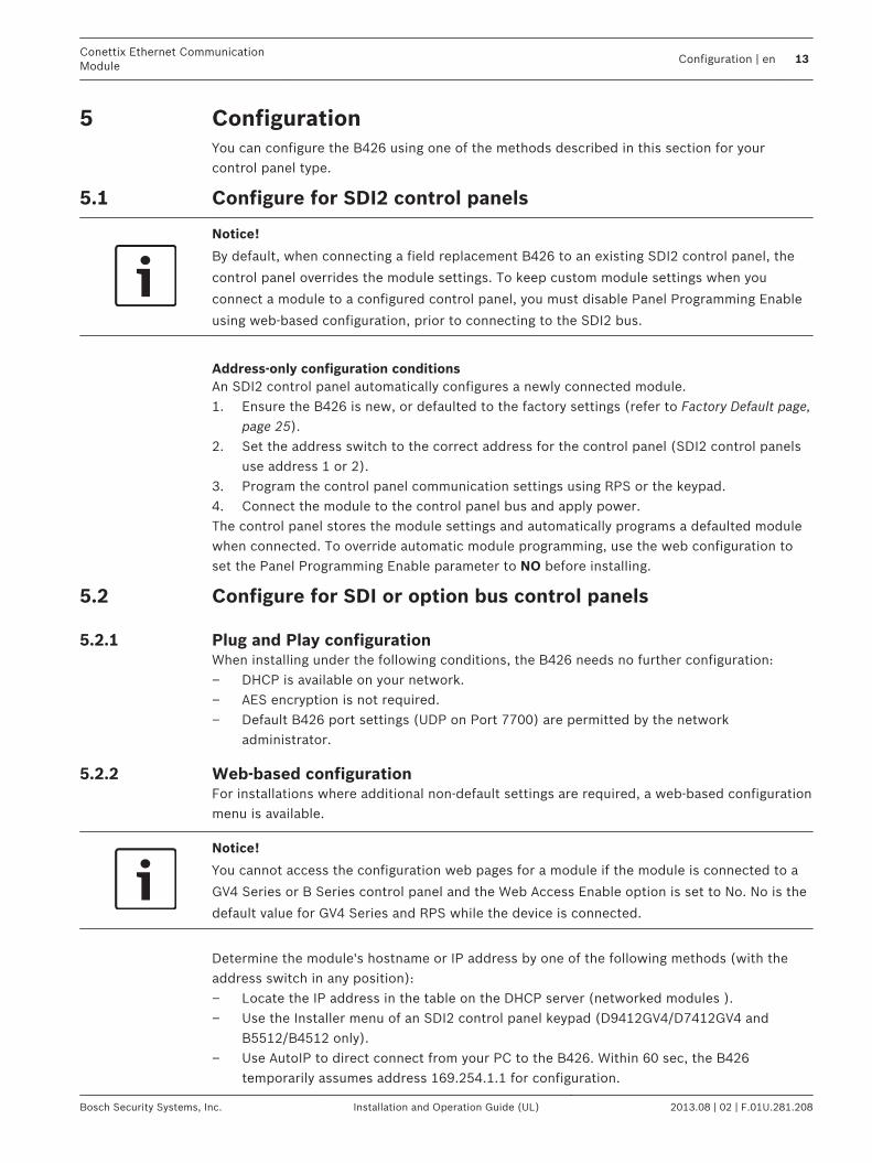
ConfigurationYou can configure the B426 using one of the methods described in this section for yourcontrol panel type.
Configure for SDI2 control panels
Notice!
By default, when connecting a field replacement B426 to an existing SDI2 control panel, the
control panel overrides the module settings. To keep custom module settings when you
connect a module to a configured control panel, you must disable Panel Programming Enable
using web-based configuration, prior to connecting to the SDI2 bus.
Address-only configuration conditionsAn SDI2 control panel automatically configures a newly connected module.1. Ensure the B426 is new, or defaulted to the factory settings (refer to Factory Default page,
page 25).2. Set the address switch to the correct address for the control panel (SDI2 control panels
use address 1 or 2).3. Program the control panel communication settings using RPS or the keypad.4. Connect the module to the control panel bus and apply power.The control panel stores the module settings and automatically programs a defaulted modulewhen connected. To override automatic module programming, use the web configuration toset the Panel Programming Enable parameter to NO before installing.
Configure for SDI or option bus control panels
Plug and Play configurationWhen installing under the following conditions, the B426 needs no further configuration:– DHCP is available on your network.– AES encryption is not required.– Default B426 port settings (UDP on Port 7700) are permitted by the network
administrator.
Web-based configurationFor installations where additional non-default settings are required, a web-based configurationmenu is available.
Notice!
You cannot access the configuration web pages for a module if the module is connected to a
GV4 Series or B Series control panel and the Web Access Enable option is set to No. No is the
default value for GV4 Series and RPS while the device is connected.
Determine the module's hostname or IP address by one of the following methods (with theaddress switch in any position):– Locate the IP address in the table on the DHCP server (networked modules ).– Use the Installer menu of an SDI2 control panel keypad (D9412GV4/D7412GV4 and
B5512/B4512 only).– Use AutoIP to direct connect from your PC to the B426. Within 60 sec, the B426
temporarily assumes address 169.254.1.1 for configuration.
5
5.1
5.2
5.2.1
5.2.2
Conettix Ethernet CommunicationModule
Configuration | en 13
Bosch Security Systems, Inc. Installation and Operation Guide (UL) 2013.08 | 02 | F.01U.281.208
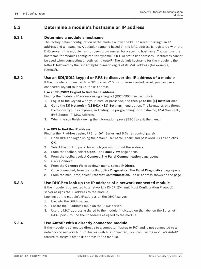
Determine a module's hostname or IP address
Determine a module’s hostnameThe factory default configuration of the module allows the DHCP server to assign an IPaddress and a hostname. A default hostname based on the MAC address is registered with theDNS server if the module has not been programmed for a specific hostname. You can use thehostname for modules configured for dynamic DHCP or static IP addresses. Hostnames cannotbe used when connecting directly using AutoIP. The default hostname for the module is theletter B followed by the last six alpha-numeric digits of its MAC address (for example,B3f603f).
Use an SDI/SDI2 keypad or RPS to discover the IP address of a moduleIf the module is connected to a GV4 Series v2.00 or B Series control panel, you can use aconnected keypad to look up the IP address.
Use an SDI/SDI2 keypad to find the IP addressFinding the module’s IP address using a keypad (B920/B930 instructions):1. Log in to the keypad with your installer passcode, and then go to the [1] Installer menu.2. Go to the [3] Network > [1] B42x > [1] Settings menu option. The keypad scrolls through
the following sub-categories, indicating the programming for: Hostname, IPv4 Source IP,IPv6 Source IP, MAC Address.
3. When the you finish viewing the information, press [ESC] to exit the menu.
Use RPS to find the IP addressFinding the IP address using RPS for GV4 Series and B Series control panels:1. Open RPS and logon using the default user name: Admin and password: 1111 and click
OK.2. Select the control panel for which you wish to find the address.3. From the toolbar, select Open. The Panel View page opens.4. From the toolbar, select Connect. The Panel Communication page opens.5. Click Connect.6. From the Connect Via drop-down menu, select IP Direct.7. Once connected, from the toolbar, click Diagnostics. The Panel Diagnostics page opens.8. From the menu tree, select Ethernet Communication. The IP address shows on the page.
Use DHCP to look up the IP address of a network-connected moduleIf the module is connected to a network, a DHCP (Dynamic Host Configuration Protocol)server assigns the IP address to the module.Looking up the module’s IP address on the DHCP server:1. Log into the DHCP server.2. Locate the IP address table on the DHCP server.3. Use the MAC address assigned to the module (indicated on the label on the Ethernet
RJ-45 port), to find the IP address assigned to the module.
Use AutoIP with a directly connected moduleIf the module is connected directly to a computer (laptop or PC) and is not connected to anetwork (no network hub, router, or switch is connected), you can use the module's AutoIPfeature to assign a static IP address to the module.
5.3
5.3.1
5.3.2
5.3.3
5.3.4
14 en | ConfigurationConettix Ethernet Communication
Module
2013.08 | 02 | F.01U.281.208 Installation and Operation Guide (UL) Bosch Security Systems, Inc.
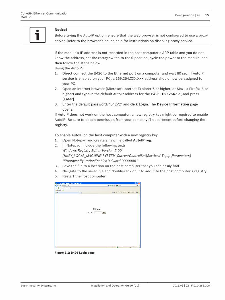
Notice!
Before trying the AutoIP option, ensure that the web browser is not configured to use a proxy
server. Refer to the browser’s online help for instructions on disabling proxy service.
If the module's IP address is not recorded in the host computer’s ARP table and you do notknow the address, set the rotary switch to the 0 position, cycle the power to the module, andthen follow the steps below.Using the AutoIP:1. Direct connect the B426 to the Ethernet port on a computer and wait 60 sec. If AutoIP
service is enabled on your PC, a 169.254.XXX.XXX address should now be assigned toyour PC.
2. Open an internet browser (Microsoft Internet Explorer 6 or higher, or Mozilla Firefox 3 orhigher) and type in the default AutoIP address for the B426: 169.254.1.1, and press[Enter].
3. Enter the default password: "B42V2" and click Login. The Device Information pageopens.
If AutoIP does not work on the host computer, a new registry key might be required to enableAutoIP. Be sure to obtain permission from your company IT department before changing theregistry. To enable AutoIP on the host computer with a new registry key:1. Open Notepad and create a new file called AutoIP.reg.2. In Notepad, include the following text:
Windows Registry Editor Version 5.00[HKEY_LOCAL_MACHINE\SYSTEM\CurrentControlSet\Services\Tcpip\Parameters]"IPAutoconfigurationEnabled"=dword:00000001
3. Save the file to a location on the host computer that you can easily find.4. Navigate to the saved file and double-click on it to add it to the host computer’s registry.5. Restart the host computer.
Figure 5.1: B426 Login page
Conettix Ethernet CommunicationModule
Configuration | en 15
Bosch Security Systems, Inc. Installation and Operation Guide (UL) 2013.08 | 02 | F.01U.281.208

Use web-based configuration menus
Notice!
Before proceeding, ensure that the web browser is not configured to use a proxy server.
Refer to the browser’s online help for instructions on disabling proxy service.
To use web-based configuration (B426 Configuration Pages):1. Open an internet browser (Microsoft Internet Explorer 6 or higher, or Mozilla Firefox 3 or
higher), type in the B426’s IP address or hostname, and press [Enter]. (If Web andAutomation Security is enabled on the B426, you must type https:// instead of http://).The B426’s Login page opens.
2. Enter the default password: B42V2 and click Login. The Device Information home pageopens.
3. Browse to the desired settings page and continue the parameters.4. Click OK.
Notice!
Before browsing to a new settings page, you must click OK to save edited values.
5. Click Save & Execute to save and apply all changes to the device.
Notice!
Ensure that the address switch is set to its proper position for communication.
You should change your password after you complete these steps to secure moduleconfiguration. Change the Web Access Password using the Maintenance page.
Device Information (home) page The Device Information page shows basic information for the module in its main pane, andprovides links to the configuration web pages along the left-hand side.
Figure 5.2: Device Information page
Refer to the following sections for descriptions of the configuration web pages.
5.4
5.5
16 en | ConfigurationConettix Ethernet Communication
Module
2013.08 | 02 | F.01U.281.208 Installation and Operation Guide (UL) Bosch Security Systems, Inc.

Change and save settings using the webThe settings for the module are grouped by topic in the left column of the web interface in themodule menu structure.Some settings (menu options) might be unavailable if:– The setting conflicts with another configured setting (for example, the Static IP setting is
unavailable when DHCP is enabled).– The setting conflicts with the address setting (for example, the Panel Address setting is
read-only if the address switch is set to anything but 0).– The setting is unavailable in the current product release.
Saving settings using the WebTo preserve edited values, click the OK button on each page before navigating to a differentsetting page (menu).To save all edited values and apply them to the module, click the Save and Execute link.
Basic Network Settings page The Basic Network Settings page disables different options, depending on whether IPv6mode is enabled or disabled.
Figure 5.3: Basic Network Settings default web page
IPv4 DHCP/AutoIP Enable
Default: YesSelections: Yes, NoYes: DHCP /AutoIP is enabled.No: DHCP/AutoIP is disabled.DHCP is an auto configuration protocol that allows a computer to be automatically configured,which eliminates the need for interaction by a network administrator. DHCP also provides acentral database that tracks computers that connect to the network, which prevents twocomputers from accidentally being configured with the same IP address.AutoIP enables dynamic IP addresses to be assigned to a device when the device is started up.Whereas DHCP requires a DHCP server, AutoIP does not require a server when selecting an IPaddress. A host configured with AutoIP receives an IP address of 169.254.xxx.xxx.
5.6
5.7
Conettix Ethernet CommunicationModule
Configuration | en 17
Bosch Security Systems, Inc. Installation and Operation Guide (UL) 2013.08 | 02 | F.01U.281.208
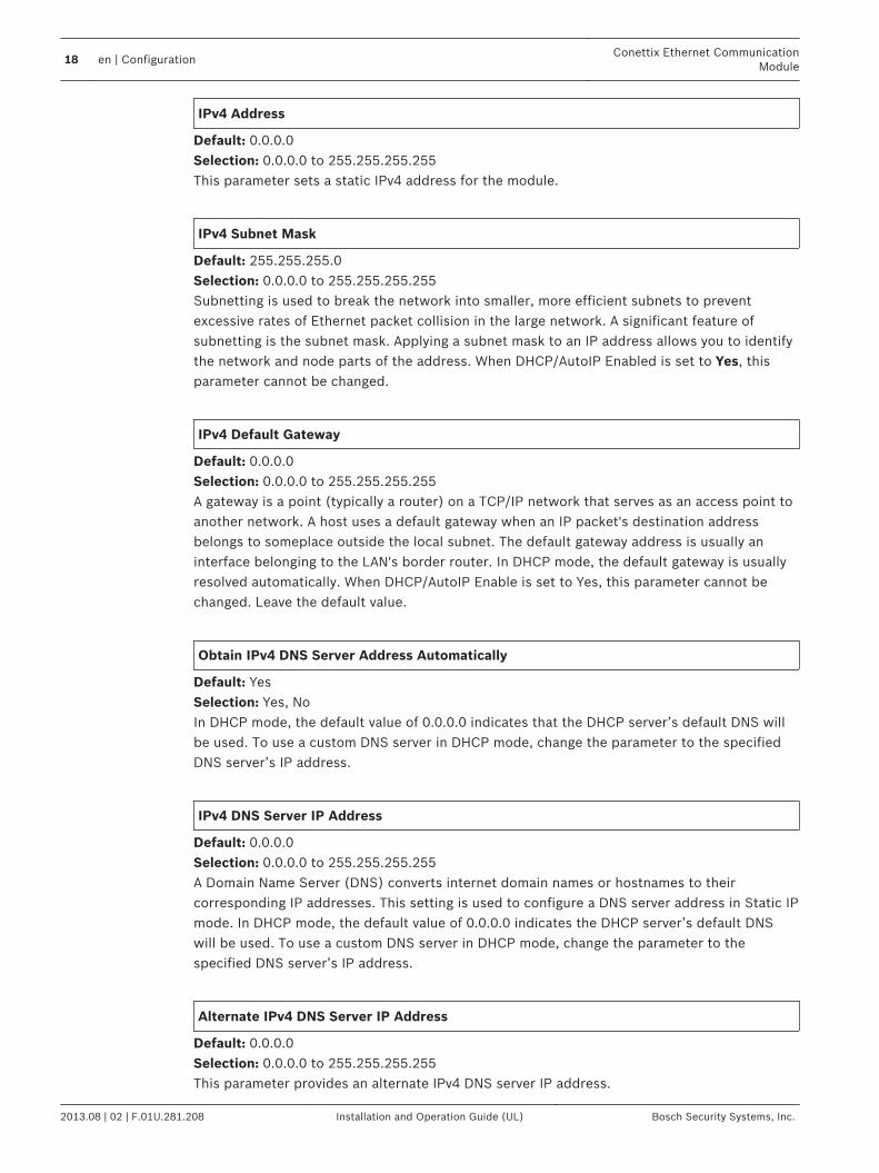
IPv4 Address
Default: 0.0.0.0Selection: 0.0.0.0 to 255.255.255.255This parameter sets a static IPv4 address for the module.
IPv4 Subnet Mask
Default: 255.255.255.0Selection: 0.0.0.0 to 255.255.255.255Subnetting is used to break the network into smaller, more efficient subnets to preventexcessive rates of Ethernet packet collision in the large network. A significant feature ofsubnetting is the subnet mask. Applying a subnet mask to an IP address allows you to identifythe network and node parts of the address. When DHCP/AutoIP Enabled is set to Yes, thisparameter cannot be changed.
IPv4 Default Gateway
Default: 0.0.0.0Selection: 0.0.0.0 to 255.255.255.255A gateway is a point (typically a router) on a TCP/IP network that serves as an access point toanother network. A host uses a default gateway when an IP packet's destination addressbelongs to someplace outside the local subnet. The default gateway address is usually aninterface belonging to the LAN's border router. In DHCP mode, the default gateway is usuallyresolved automatically. When DHCP/AutoIP Enable is set to Yes, this parameter cannot bechanged. Leave the default value.
Obtain IPv4 DNS Server Address Automatically
Default: YesSelection: Yes, NoIn DHCP mode, the default value of 0.0.0.0 indicates that the DHCP server’s default DNS willbe used. To use a custom DNS server in DHCP mode, change the parameter to the specifiedDNS server’s IP address.
IPv4 DNS Server IP Address
Default: 0.0.0.0Selection: 0.0.0.0 to 255.255.255.255A Domain Name Server (DNS) converts internet domain names or hostnames to theircorresponding IP addresses. This setting is used to configure a DNS server address in Static IPmode. In DHCP mode, the default value of 0.0.0.0 indicates the DHCP server’s default DNSwill be used. To use a custom DNS server in DHCP mode, change the parameter to thespecified DNS server’s IP address.
Alternate IPv4 DNS Server IP Address
Default: 0.0.0.0Selection: 0.0.0.0 to 255.255.255.255This parameter provides an alternate IPv4 DNS server IP address.
18 en | ConfigurationConettix Ethernet Communication
Module
2013.08 | 02 | F.01U.281.208 Installation and Operation Guide (UL) Bosch Security Systems, Inc.

If the module fails to obtain an address from the primary server, the alternate DNS server isused, if specified. The alternate address has a dot decimal notation, which consists of the fouroctets of the address expressed separately in decimal and separated by periods. Each octethas a value 0-255. When this is defined through the DHCP service, leave the default value.
IPv6 Mode
Default: DisableSelections: Enable, DisableEnable: IPv6 enabled; module works with IPv6 addressing.Disable: IPv6 disabled; module works with IPv4 addressing.IP Version 6 (IPv6) is a new version of Internet Protocol. Select whether the module workswith IPv6 or IPv4 addressing.
Obtain IPv6 DNS Server Address Automatically
Default: NoSelection: Yes, NoIn DHCP mode, the default value of 0:0:0:0:0:0:0:0 indicates that the DHCP server’s defaultDNS is used. To use a custom DNS server in DHCP mode, change the parameter to thespecified DNS server’s IP address.
IPv6 DNS Server IP Address
Default: 0:0:0:0:0:0:0:0Selection: 0:0:0:0:0:0:0:0 to FFFF:FFFF:FFFF:FFFF:FFFF:FFFF:FFFF:FFFFThis parameter configures the IPv6 DNS server address in Static IP mode.A DNS server converts internet domain names or hostnames to their corresponding IPaddresses. In DHCP mode, the default value indicates the DHCP server’s default DNS is used.To use a custom DNS server in DHCP mode, change the parameter to the specified DNSserver’s IP address.The IPv6 DNS address has a dot decimal notation, which consists of the eight octets of theaddress expressed separately in decimal and separated by colons. Each octet has a value 0-FFFF. When this is defined through the DHCP service, leave the default value.For IPv6, only the DNS server addresses are entered as numbers. All other entries should belimited to IPv6 addresses or DNS names.
Alternate IPv6 DNS Server IP Address
Default: 0:0:0:0:0:0:0:0Selection: 0:0:0:0:0:0:0:0 to FFFF:FFFF:FFFF:FFFF:FFFF:FFFF:FFFF:FFFFThis parameter provides an alternate IPv6 DNS server IP address.If the module fails to obtain an address from the primary server, the alternate IPv6 DNS serveris used, if specified. The alternate IPv6 DNS address has a dot decimal notation, whichconsists of the eight octets of the address expressed separately in decimal and separated bycolons. Each octet has a value 0-255. When this is defined through the DHCP service, leave thedefault value.
TCP/UDP Port Number
Conettix Ethernet CommunicationModule
Configuration | en 19
Bosch Security Systems, Inc. Installation and Operation Guide (UL) 2013.08 | 02 | F.01U.281.208

Default: 7700Selection: 0 to 65535This parameter sets the local port number that the module listens to for in-coming networktraffic.The TCP/UDP Port is typically configured as 7700 when the control panel is communicatingwith the B5512 and B4512, a central station receiver, RPS, Automation or Remote SecurityControl. Port numbers are assigned in various ways based on three ranges:– System Ports: 0 to 1023– User Ports: 1024 to 49151– Dynamic or Private Ports: 49152 to 65535Note: In order to limit unwanted traffic, select a number above 1023.
Legacy TCP Automation Enable
Default: NoSelection: Yes, NoWhen enabled, creates and maintains two separate TCP connections used to interface withautomation software or Remote Security Control (RSC) application on B Series control panels.
TCP Keep Alive Time
Default: 45Selection: 0 – 65 (0: Disable, 1 - 65: Keepalive Time in sec)Select how many seconds the unit waits during a silent connection before attempting to see ifthe currently connected network device is still on the network. If there is no response, itdrops the connection.
Advanced Network Settings page
Figure 5.4: Advanced Network Settings page
Legacy Panel Mode
Default: 0 (Disable)Selections: 0, 10: Legacy Panel Mode is disabled.
5.8
20 en | ConfigurationConettix Ethernet Communication
Module
2013.08 | 02 | F.01U.281.208 Installation and Operation Guide (UL) Bosch Security Systems, Inc.

1: Legacy Panel Mode is enabled.This option allows the module to support legacy control panels that communicate usingDatagram Mode 0. When Legacy Panel Mode is enabled, the module uses the Local Portparameter as both the source port and destination port for communication.The control panels that use Legacy Panel Mode are:– GV2 Series v7.05 and lower– G Series v6.99 and lower– DS7400XiV4
Port 77EE Configuration Enable
Default: NoSelections: Yes, NoYes: The network configuration port is enabled. The remote application software can configurethe module through this port.No: The network configuration port is disabled. The remote application software cannotconfigure the module through this port.Port number 77EE (hexadecimal code) is reserved for configuration of the module by theremote application software.
UPnP Enable
Default: YesSelections: Yes, NoYes: UPnP is enabled.No: UPnP is disabled.Universal Plug and Play (UPnP) allows devices to connect seamlessly and simplifies theimplementation of personal and corporate networks. When enabled in the premises router,this feature is used to automatically setup port forwarding rules for Remote Programmingtraffic to the control panel.
HTTP Port Number
Default: 80Selections: 1 to 65535Use this option to configure the port number for the module web server.
ARP Cache Timeout
Default: 600Selections: 1 to 600 (in 1-sec increments)When the module communicates with any device on a network, an entry is added to its ARPtable for each of those devices. The ARP Cache Timeout defines the number of seconds (1 to600) before the ARP table of the module is refreshed.
Panel Address Settings pageThe Panel Address Setting option only works when the address rotary switch on the moduleis set to 0 (local configuration setting). If the address switch is set to a position other than 0,the set address is displayed.
5.9
Conettix Ethernet CommunicationModule
Configuration | en 21
Bosch Security Systems, Inc. Installation and Operation Guide (UL) 2013.08 | 02 | F.01U.281.208
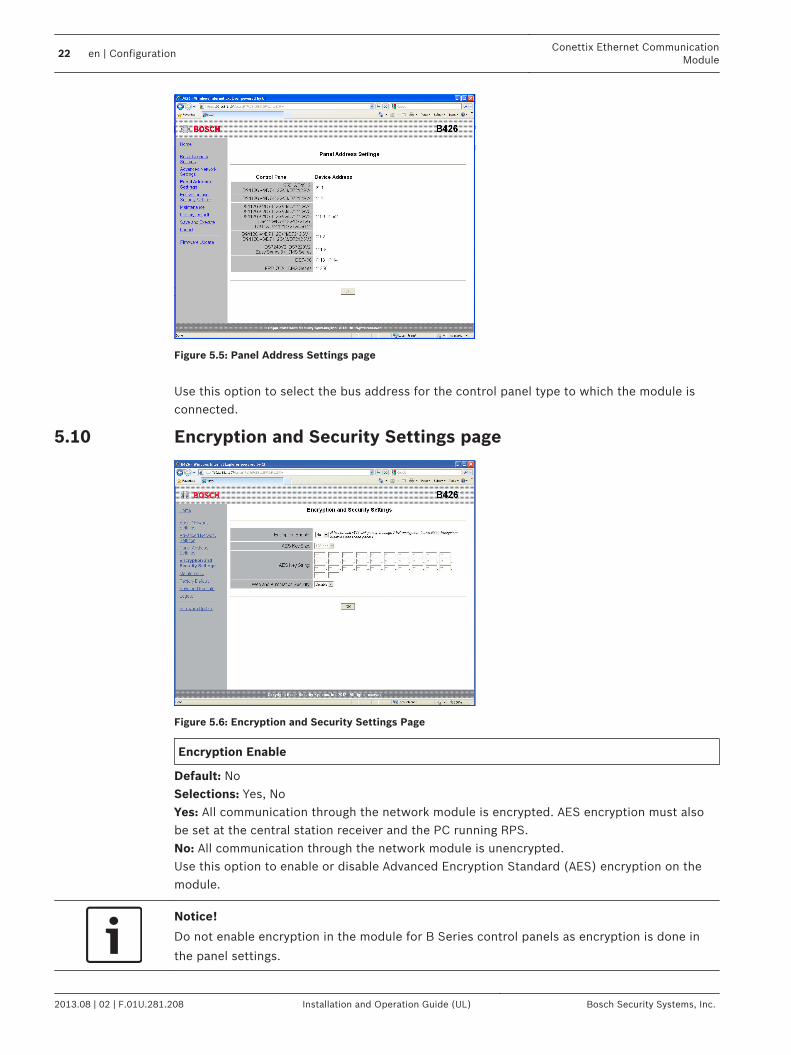
Figure 5.5: Panel Address Settings page
Use this option to select the bus address for the control panel type to which the module isconnected.
Encryption and Security Settings page
Figure 5.6: Encryption and Security Settings Page
Encryption Enable
Default: NoSelections: Yes, NoYes: All communication through the network module is encrypted. AES encryption must alsobe set at the central station receiver and the PC running RPS.No: All communication through the network module is unencrypted.Use this option to enable or disable Advanced Encryption Standard (AES) encryption on themodule.
Notice!
Do not enable encryption in the module for B Series control panels as encryption is done in
the panel settings.
5.10
22 en | ConfigurationConettix Ethernet Communication
Module
2013.08 | 02 | F.01U.281.208 Installation and Operation Guide (UL) Bosch Security Systems, Inc.

AES Key Size
Default: 128Selections: 128, 192, 256Use this option to select the AES key size. The AES key size must match the key size used inRPSand the receiver.
AES Key String
Default: 01 to 16Selections: Sixty-four hexadecimal characters represented in up to 32 fields (2 hexadecimalcharacters per field)– 128 bit key length is 16 bytes (16 fields displaying 2 ASCII [0-9, A-F] characters).– 192 bit key length is 24 bytes (24 fields displaying 2 ASCII [0-9, A-F] characters).– 256 bit key length is 32 bytes. (32 fields displaying 2 ASCII [0-9, A-F] characters).
Web and Automation Security
Default: EnableSelections: Disable, EnableThis parameter enables enhanced security for Automation and B426 Web Access.When enabled, HTTPS is applied to B426 Web Access changing the default value of the HTTPport number parameter. This setting also enables TLS Security for Automation.
Maintenance page
Figure 5.7: Maintenance page
Web Access Password
Default: B42V2Selections: Four to ten case sensitive alphanumeric charactersEnter the password to log in to the configuration web pages. It is recommended to change thedefault login password to ensure configuration settings. It is recommended to change yourpassword for security of the module configuration.
5.11
Conettix Ethernet CommunicationModule
Configuration | en 23
Bosch Security Systems, Inc. Installation and Operation Guide (UL) 2013.08 | 02 | F.01U.281.208
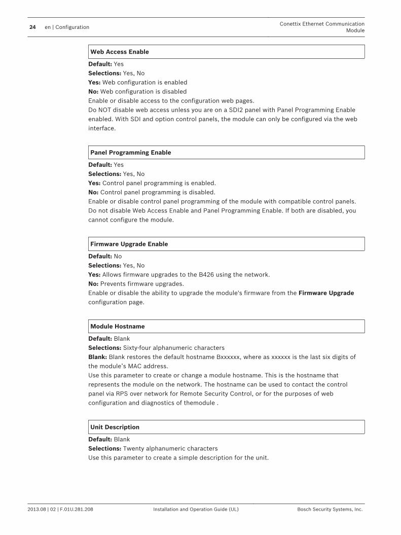
Web Access Enable
Default: YesSelections: Yes, NoYes: Web configuration is enabledNo: Web configuration is disabledEnable or disable access to the configuration web pages.Do NOT disable web access unless you are on a SDI2 panel with Panel Programming Enableenabled. With SDI and option control panels, the module can only be configured via the webinterface.
Panel Programming Enable
Default: YesSelections: Yes, NoYes: Control panel programming is enabled.No: Control panel programming is disabled.Enable or disable control panel programming of the module with compatible control panels.Do not disable Web Access Enable and Panel Programming Enable. If both are disabled, youcannot configure the module.
Firmware Upgrade Enable
Default: NoSelections: Yes, NoYes: Allows firmware upgrades to the B426 using the network.No: Prevents firmware upgrades.Enable or disable the ability to upgrade the module's firmware from the Firmware Upgradeconfiguration page.
Module Hostname
Default: BlankSelections: Sixty-four alphanumeric charactersBlank: Blank restores the default hostname Bxxxxxx, where as xxxxxx is the last six digits ofthe module’s MAC address.Use this parameter to create or change a module hostname. This is the hostname thatrepresents the module on the network. The hostname can be used to contact the controlpanel via RPS over network for Remote Security Control, or for the purposes of webconfiguration and diagnostics of themodule .
Unit Description
Default: BlankSelections: Twenty alphanumeric charactersUse this parameter to create a simple description for the unit.
24 en | ConfigurationConettix Ethernet Communication
Module
2013.08 | 02 | F.01U.281.208 Installation and Operation Guide (UL) Bosch Security Systems, Inc.

Factory Default page
Figure 5.8: Factory Default page
You can return the module to the factory default settings by clicking on the Factory Defaultmenu.Click Cancel to cancel the factory default reset. If you select OK, all configuration options arereturned to the factory default settings.
Notice!
Returning the module to its factory default settings might cause the module to terminate the
current web browsing session. If connected to a compatible SDI2 control panel with Panel
Programming Enable enabled, the control panel overwrites the factory default settings with
the control panel's settings. To avoid the control panel settings overwriting Configuration
Page settings, set Panel Programming Enable to No after restoring the module to factory
default, but before pressing Save and Execute.
Firmware Update pageTo upgrade the firmware in the module, select the Firmware Update option from theconfiguration home page. The Firmware Update page opens.
Figure 5.9: Firmware Update page
5.12
5.13
Conettix Ethernet CommunicationModule
Configuration | en 25
Bosch Security Systems, Inc. Installation and Operation Guide (UL) 2013.08 | 02 | F.01U.281.208

To proceed with the upgrade, click OK. A new web page opens that allows you to locate thefirmware file and upload it to the module.
Figure 5.10: Firmware upgrade specify upgrade file
Notice!
Upgrading the firmware in the module might cause the module to terminate the current web
browsing session.
Exiting the web-based configuration pagesWhen you are finished configuring the module, select the Save and Execute option. The Saveand Execute web page opens.To save the configuration changes that you made, click OK. A confirmation message appears.
Figure 5.11: Save and Execute confirmation
To exit the configuration web page, click Logout, and then close the internet browser window.
5.14
26 en | ConfigurationConettix Ethernet Communication
Module
2013.08 | 02 | F.01U.281.208 Installation and Operation Guide (UL) Bosch Security Systems, Inc.
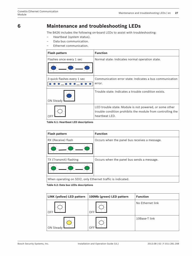
Maintenance and troubleshooting LEDsThe B426 includes the following on-board LEDs to assist with troubleshooting:– Heartbeat (system status).– Data bus communication.– Ethernet communication.
Flash pattern Function
Flashes once every 1 sec Normal state: Indicates normal operation state.
3 quick flashes every 1 sec Communication error state: Indicates a bus communicationerror.
ON Steady
Trouble state: Indicates a trouble condition exists.
OFF
LED trouble state: Module is not powered, or some othertrouble condition prohibits the module from controlling theheartbeat LED.
Table 6.1: Heartbeat LED descriptions
Flash pattern Function
RX (Receive) flash Occurs when the panel bus receives a message.
TX (Transmit) flashing Occurs when the panel bus sends a message.
When operating on SDI2, only Ethernet traffic is indicated.
Table 6.2: Data bus LEDs descriptions
LINK (yellow) LED pattern 100Mb (green) LED pattern Function
OFF OFF
No Ethernet link
ON Steady OFF
10Base-T link
6
Conettix Ethernet CommunicationModule
Maintenance and troubleshooting LEDs | en 27
Bosch Security Systems, Inc. Installation and Operation Guide (UL) 2013.08 | 02 | F.01U.281.208

LINK (yellow) LED pattern 100Mb (green) LED pattern Function
Flashing
OFF
10Base-T activity
ON Steady ON Steady
100Base-TX link
Flashing
ON Steady
100Base-TX activity
Table 6.3: Ethernet Link LEDs descriptions
Refer to B426 module overview, page 8 for Ethernet link LED descriptions.
Show the firmware versionTo show the firmware version using an LED flash pattern:– If the optional tamper switch is installed:
With the enclosure door open, activate the tamper switch.– If the optional tamper switch is NOT installed:
Momentarily short the tamper pins.When the tamper switch is activated (closed to open), the heartbeat LED stays OFF for 3 secbefore indicating the firmware version. The LED pulses the major, minor, and micro digits ofthe firmware version, with a 1 sec pause after each digit.Flashing patterns do not start until the tamper is open (short is removed). The following is anexample: The version 1.4.3 would be shown as LED flashes:[3 second pause] *___****___*** [3 second pause, then normal operation].
Figure 6.1: Firmware LED flash patterns example
6.1
28 en | Maintenance and troubleshooting LEDsConettix Ethernet Communication
Module
2013.08 | 02 | F.01U.281.208 Installation and Operation Guide (UL) Bosch Security Systems, Inc.
Specifications and certifications
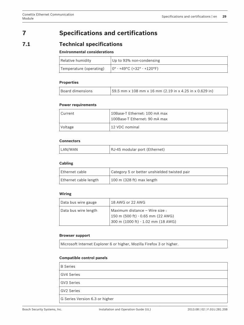
Technical specificationsEnvironmental considerations
Relative humidity Up to 93% non-condensing
Temperature (operating) 0° - +49°C (+32° - +120°F)
Properties
Board dimensions 59.5 mm x 108 mm x 16 mm (2.19 in x 4.25 in x 0.629 in)
Power requirements
Current 10Base-T Ethernet: 100 mA max100Base-T Ethernet: 90 mA max
Voltage 12 VDC nominal
Connectors
LAN/WAN RJ-45 modular port (Ethernet)
Cabling
Ethernet cable Category 5 or better unshielded twisted pair
Ethernet cable length 100 m (328 ft) max length
Wiring
Data bus wire gauge 18 AWG or 22 AWG
Data bus wire length Maximum distance – Wire size :150 m (500 ft) - 0.65 mm (22 AWG)300 m (1000 ft) - 1.02 mm (18 AWG)
Browser support
Microsoft Internet Explorer 6 or higher, Mozilla Firefox 3 or higher.
Compatible control panels
B Series
GV4 Series
GV3 Series
GV2 Series
G Series Version 6.3 or higher
7
7.1
Conettix Ethernet CommunicationModule
Specifications and certifications | en 29
Bosch Security Systems, Inc. Installation and Operation Guide (UL) 2013.08 | 02 | F.01U.281.208

D9412
D7412
D7212
D9112
Certifications
Region Certification Applicable controlpanels
US UL 365 - Police Station Connected Burglar AlarmUnits and Systems
B5512/B4512/B3512,GV4 Series, GV3Series, GV2 Series
UL 609 - Local Burglar Alarm Units and Systems B5512/B4512/B3512,GV4 Series, GV3Series, GV2 Series
UL 864 - Control Units and Accessories for Fire AlarmSystems (Including NFPA 72)
GV4 Series, GV3Series, GV2 Series,FPD-7024
UL 985 – Household Fire Warning System Units B5512/B4512/B3512,GV4 Series, GV3Series, GV2 Series
UL 1023 – Household Burglar Alarm System Units B5512/B4512/B3512,GV4 Series, GV3Series, GV2 Series
UL 1076 – Proprietary Burglar Alarm Units andSystems
B5512/B4512/B3512,GV4 Series, GV3Series, GV2 Series
UL 1610 - Central Station Burglar Alarm Units B5512/B4512/B3512,GV4 Series, GV3Series, GV2 Series
FCC Part 15 Class B B5512/B4512/B3512,GV4 Series, GV3Series, GV2 Series, GSeries
Canada CAN/ULC S303 - Local Burglar Alarm Units andSystems
B5512/B4512/B3512,GV4 Series, GV3Series, GV2 Series
CAN/ULC S304 - Signal Receiving Centre and PremiseAlarm Control Units
B5512/B4512/B3512,GV4 Series, GV3Series, GV2 Series
7.2
30 en | Specifications and certificationsConettix Ethernet Communication
Module
2013.08 | 02 | F.01U.281.208 Installation and Operation Guide (UL) Bosch Security Systems, Inc.
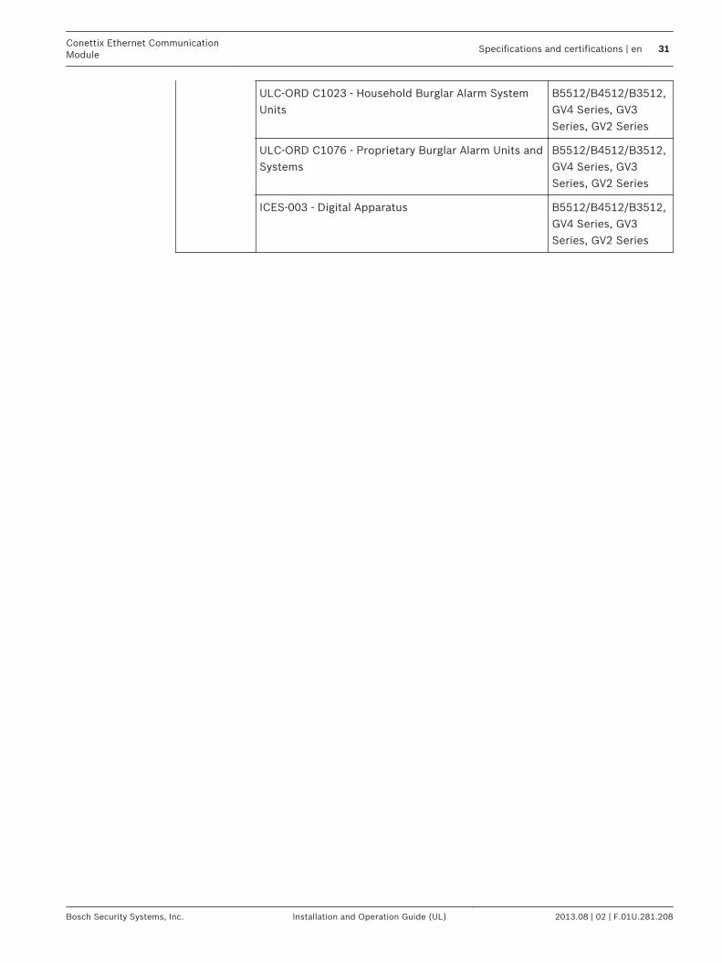
ULC-ORD C1023 - Household Burglar Alarm SystemUnits
B5512/B4512/B3512,GV4 Series, GV3Series, GV2 Series
ULC-ORD C1076 - Proprietary Burglar Alarm Units andSystems
B5512/B4512/B3512,GV4 Series, GV3Series, GV2 Series
ICES-003 - Digital Apparatus B5512/B4512/B3512,GV4 Series, GV3Series, GV2 Series
Conettix Ethernet CommunicationModule
Specifications and certifications | en 31
Bosch Security Systems, Inc. Installation and Operation Guide (UL) 2013.08 | 02 | F.01U.281.208


Bosch Security Systems, Inc.
130 Perinton Parkway
Fairport, NY 14450
USA
www.boschsecurity.com
© Bosch Security Systems, Inc., 2013