
Conducted susceptibility - volta.it · •Conducted susceptibility •Power leads •DC and AC, I...
117
Transcript of Conducted susceptibility - volta.it · •Conducted susceptibility •Power leads •DC and AC, I...
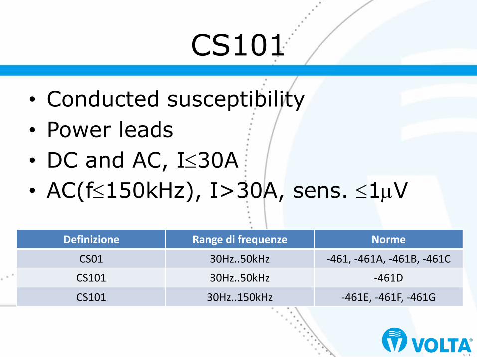
• Conducted susceptibility
• Power leads
• DC and AC, I30A
• AC(f150kHz), I>30A, sens. 1V
CS101
Definizione Range di frequenze Norme
CS01 30Hz..50kHz -461, -461A, -461B, -461C
CS101 30Hz..50kHz -461D
CS101 30Hz..150kHz -461E, -461F, -461G

Applicazioni MIL-STD-461G CS101
Surface ships A
Submarines A
Aircraft, Army, Including Flight Line A
Aircraft, Navy A
Aircraft, Air Force A
Space systems, Including Launch Vehicles A
Ground, Army A
Ground, Navy A
Ground, Air Force A
Le applicazioni
A: Applicable L: Limited as specified in the individual sections of the standard S: Procuring activity must specify in procurement documentation

• MIL-STD-461G 5.7.1 – This requirement is applicable from 30Hz to
150kHz for equipment and subsystem AC, limited to current draws ≤ 30A per phase, and DC input power leads, not including returns. This is also applicable to systems that draw more than 30A if the system has an operating frequency 150kHz or less and an operating sensitivity of 1μV or better (such as 0.5μV). If the EUT is DC operated, this requirement is applicable over the frequency range of 30Hz to 150kHz. If the EUT is AC operated, this requirement is applicable starting from the second harmonic of the EUT power frequency and extending to 150kHz.
CS101 applicability
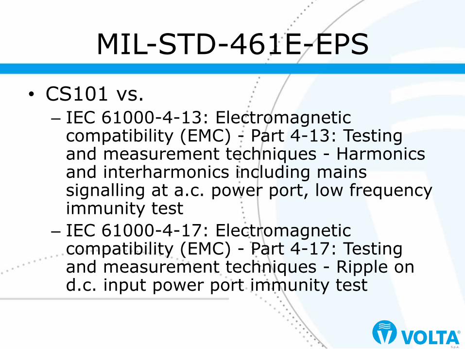
• CS101 vs. – IEC 61000-4-13: Electromagnetic
compatibility (EMC) - Part 4-13: Testing and measurement techniques - Harmonics and interharmonics including mains signalling at a.c. power port, low frequency immunity test
– IEC 61000-4-17: Electromagnetic compatibility (EMC) - Part 4-17: Testing and measurement techniques - Ripple on d.c. input power port immunity test
MIL-STD-461E-EPS

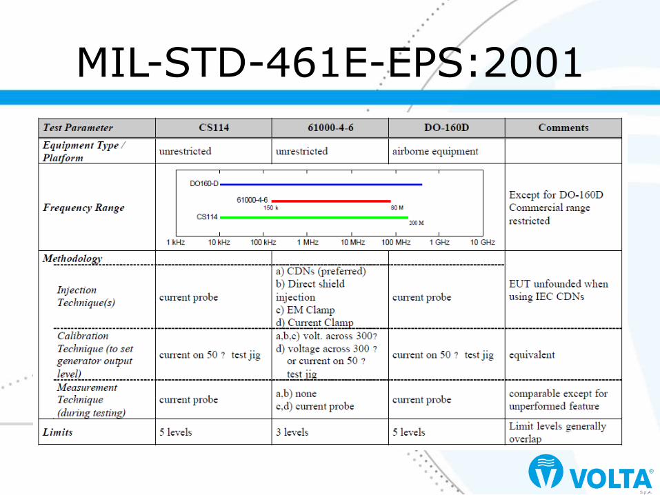
MIL-STD-461E-EPS:2001

• 6.4.1.1 Frequency Coverage – IEC 61000-4-13 covers only harmonics up to the
40th harmonic of the mains frequency (2.4kHz) and interharmonics from 16Hz to 2.4kHz, whereas, CS101 covers the range from 30Hz to 150kHz. Due to the limited frequency coverage, IEC 61000-4-13 certified equipment can only be considered for CS101 qualification if the major interference sources on the power mains are harmonics of the supply frequency. If other system loads contain switching power supplies, static frequency converters, induction motors, welding machines, or ISM equipment, IEC 61000-4-13 certification would probably not be sufficient.
MIL-STD-461E-EPS:2001

• 6.4.1.4 Conclusion – For commercial equipment being procured
by the military, both IEC 61000-4-13 and DO-160D (with appropriate categories specified) will provide a known level of immunity for equipment certified to these standards. This is particularly true if the primary threat environment is harmonics of the power frequency. Neither of these specifications will provide adequate protection for the very low frequency threat of some navy platforms.
MIL-STD-461E-EPS:2001
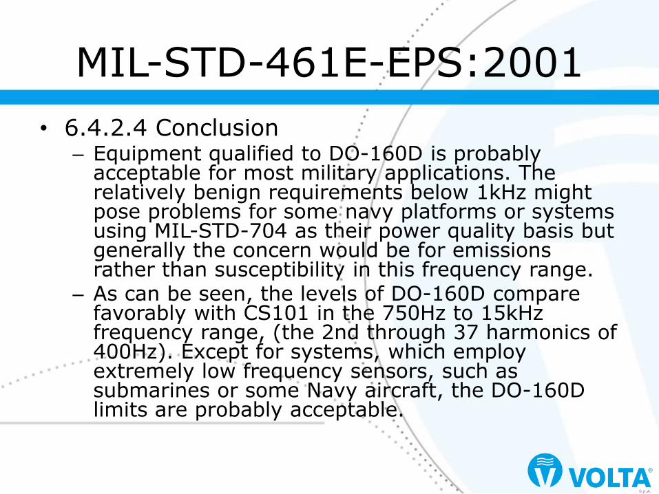
• 6.4.2.4 Conclusion – Equipment qualified to DO-160D is probably
acceptable for most military applications. The relatively benign requirements below 1kHz might pose problems for some navy platforms or systems using MIL-STD-704 as their power quality basis but generally the concern would be for emissions rather than susceptibility in this frequency range.
– As can be seen, the levels of DO-160D compare favorably with CS101 in the 750Hz to 15kHz frequency range, (the 2nd through 37 harmonics of 400Hz). Except for systems, which employ extremely low frequency sensors, such as submarines or some Navy aircraft, the DO-160D limits are probably acceptable.
MIL-STD-461E-EPS:2001

• 5.7.3.2: Test equipment – Signal generator
– Power amplifier
– Oscilloscope or measurement receiver
– Coupling transformer
– Capacitor, 10F
– Isolation transformer for oscilloscope or transducer for measurement receiver use
– Resistor, 0.5
– LISNs
MIL-STD-461G

• 5.7.3.4.b – A partire dalla minima frequenza,
applicare un segnale fino a verificare il livello di tensione della potenza massima richiesta dai limiti di Figure CS101-2. Verificare che la forma d’onda sia sinusoidale se si usa oscilloscopio.
– Registrare i parametri e continuare con lo sweep in frequenza fino a quella massima.
Integrity check

Integrity check

• 5.7.3.4.c – Azionare l’EUT e lasciarlo stabilizzare
– Attenzione: il safety ground dell’oscilloscopio è disconnesso a causa del trasformatore di isolamento e ciò implica rischio di shock!
– A partire dalla frequenza più bassa, applicare un segnale fino a raggiungere la tensione o il livello di potenza richiesto, limitato dal livello calibrato
EUT testing

• 5.7.3.4.c
– Mantenere il livello di segnale e scansire sulla banda di frequenze richieste come da Table III
– Controllare l’EUT e, in caso di degrado della performance, agire come da 4.3.10.4.3
– Ripetere per ogni power lead
EUT testing

EUT testing

EUT testing

EUT testing

• Conducted susceptibility
• Power leads
• Eliminata da MIL-STD-461D
CS02
Definizione Range di frequenze Norme
CS02 50kHz..400MHz -461, -461A, -461B, -461C

• Conducted susceptibility
• Intermodulation, antenna port
• Receivers and transceivers
CS103
Definizione Range di frequenze Norme
CS03 30Hz..10GHz -461, -461A
CS03 15kHz..10GHz -461B, -461C
CS103 15kHz..10GHz -461D, -461E, -461F, -461G

Applicazioni MIL-STD-461G CS103
Surface ships S
Submarines S
Aircraft, Army, Including Flight Line S
Aircraft, Navy S
Aircraft, Air Force S
Space systems, Including Launch Vehicles S
Ground, Army S
Ground, Navy S
Ground, Air Force S
Le applicazioni
A: Applicable L: Limited as specified in the individual sections of the standard S: Procuring activity must specify in procurement documentation

• MIL-STD-461G 5.8.1
– This receiver front-end susceptibility requirement is applicable from 15kHz to 10GHz for equipment and subsystems, such as communications receivers, RF amplifiers, transceivers, radar receivers, acoustic receivers, and electronic warfare receivers as specified in the individual procurement specification
CS103 applicability

• MIL-STD-461G A.5.8 – The intent of this requirement is to control the
response of antenna-connected receiving subsystems to in-band signals resulting from potential intermodulation products of two signals outside of the intentional passband of the subsystem produced by non-linearities in the subsystem. Due to the wide diversity of subsystem designs being developed, the applicability of this type of requirement and appropriate limits need to be determined for each procurement. Also, requirements need to be specified that are consistent with the signal processing characteristics of the subsystem and the particular test procedures to be used to verify the requirement.
CS103 applicability

• MIL-STD-461G A.5.8 – No test procedures are provided in the
main body of this standard for this requirement. Because of the large variety of receiver designs being developed, the requirements for the specific operational characteristics of a receiver must be established before meaningful test procedures can be developed. Only general testing techniques are discussed in this appendix.
EUT testing

EUT testing

• Conducted susceptibility
• Rejection of undesired signals, antenna port
• Receivers and transceivers
CS104
Definizione Range di frequenze Norme
CS04 30Hz..10GHz -461, -461A
CS04 30Hz..20GHz -461B, -461C
CS104 30Hz..20GHz -461D, -461E, -461F, -461G
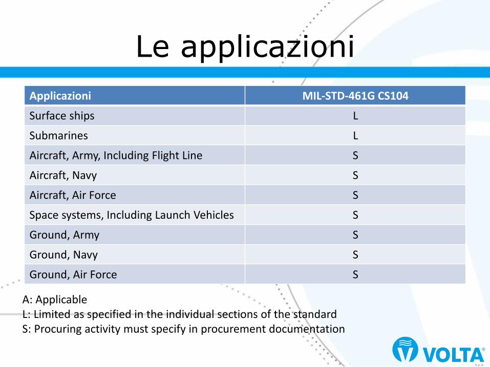
Applicazioni MIL-STD-461G CS104
Surface ships L
Submarines L
Aircraft, Army, Including Flight Line S
Aircraft, Navy S
Aircraft, Air Force S
Space systems, Including Launch Vehicles S
Ground, Army S
Ground, Navy S
Ground, Air Force S
Le applicazioni
A: Applicable L: Limited as specified in the individual sections of the standard S: Procuring activity must specify in procurement documentation

• MIL-STD-461G 5.9.1 – This receiver front-end susceptibility
requirement is applicable from 30Hz to 20GHz for equipment and subsystems, such as communications receivers, RF amplifiers, transceivers, radar receivers, acoustic receivers, and electronic warfare receivers as specified in the individual procurement specification. For Navy ships and submarines, this requirement is applicable for all receivers. The applicable frequencies are a function of the front-end design of the unit being evaluated.
CS104 applicability
• MIL-STD-461G A.5.9 – The intent of this requirement is to control the
response of antenna-connected receiving subsystems to signals outside of the intentional passband of the subsystem. The requirement can be applied to receivers, transceivers, amplifiers, and the like. Due to the wide diversity of subsystem designs being developed, the applicability of this type of requirement and appropriate limits need to be determined for each procurement. Also, requirements need to be specified that are consistent with the signal processing characteristics of the subsystem and the particular test procedures to be used to verify the requirement.
CS104 applicability

• MIL-STD-461G A.5.0 – No test procedures are provided in the
main body of this standard for this requirement. Because of the large variety of receiver designs being developed, the requirements for the specific operational characteristics of a receiver must be established before meaningful test procedures can be developed. Only general testing techniques are discussed in this appendix.
EUT testing

EUT testing

• Conducted susceptibility
• Cross-modulation, antenna port
• Receivers and transceivers
CS105
Definizione Range di frequenze Norme
CS05 30Hz..10GHz -461, -461A
CS05 30Hz..20GHz -461B, -461C
CS105 30Hz..20GHz -461D, -461E, -461F, -461G

Applicazioni MIL-STD-461G CS105
Surface ships S
Submarines S
Aircraft, Army, Including Flight Line S
Aircraft, Navy S
Aircraft, Air Force S
Space systems, Including Launch Vehicles S
Ground, Army S
Ground, Navy S
Ground, Air Force S
Le applicazioni
A: Applicable L: Limited as specified in the individual sections of the standard S: Procuring activity must specify in procurement documentation

• MIL-STD-461G 5.10.1
– This receiver front-end susceptibility requirement is applicable from 30Hz to 20GHz only for receivers that normally process amplitude-modulated RF signals, as specified in the individual procurement specification.
CS105 applicability

• MIL-STD-461G A.5.10 – The intent of this requirement is to control the response of
antenna-connected receiving subsystems to modulation being transferred from an out-of-band signal to an in-band signal. This effect results from a strong, out-of-band signal near the operating frequency of the receiver that modulates the gain in the front-end of the receiver and adds amplitude varying information to the desired signal. The requirement should be considered only for receivers, transceivers, amplifiers, and the like, which extract information from the amplitude modulation of a carrier. Due to the wide diversity of subsystem designs being developed, the applicability of this type of requirement and appropriate limits need to be determined for each procurement. Also, requirements need to be specified that are consistent with the signal processing characteristics of the subsystem and the particular test procedure to be used to verify the requirement.
CS105 applicability
• MIL-STD-461G A.5.0 – No test procedures are provided in the
main body of this standard for this requirement. Because of the large variety of receiver designs being developed, the requirements for the specific operational characteristics of a receiver must be established before meaningful test procedures can be developed. Only general testing techniques are discussed in this appendix.
EUT testing

EUT testing

• Conducted susceptibility
• Spike / Transients, Power leads
• Eliminata da MIL-STD-461G
CS106
Definizione Range di frequenze Norme
CS06 Spike -461, -461A, -461B, -461C
CS106 Transient -461F

• MIL-STD-461F A.5.11 – The requirement is applicable to power
input leads on surface ships and submarines that obtain power from the platform’s primary power source that are not part of the EUT. There is no requirement on power output leads. The primary concern is to ensure that equipment performance is not degraded from voltage transients experienced on shipboard power systems coupling to interface wiring inside enclosures.
CS106

• MIL-STD-461F A.5.11 – The Navy submarine community has found the
obsolete CS06 of MIL-STD-461 (through revision C) requirement to be an effective method to minimize risk of transient-related equipment and subsystem susceptibility. The CS106 type transient test has been successful in early identification of transient related EMI problems in naval equipment and subsystems. The Navy has found good correlation between transient related shipboard EMI problems (including longevity, degraded performance and premature failures) and CS106 susceptibilities.
CS106
• MIL-STD-461G A.5.1 – CS106 was added in MIL-STD-461F and is
deleted in MIL-STD-461G. The rationale for adding it was included in the MIL-STD-461F rationale appendix. The underlying issue was not the response of the power supply to the transient, but crosstalk within an equipment between the transient on the power wiring and signals carried on wiring adjacent to the power wires without adequate protection. The purpose of the requirement was to force adequate segregation between power and signal circuitry.
CS106
• MIL-STD-461G A.5.1 – However, CS115/CS116 was designed specifically
to represent the coupling of transients on a power bus into cables run adjacent to it. The very short 30ns duration and even shorter 2ns rise and fall times of CS115 represent the leading edge of a waveform such as CS106 on a power bus inductively coupling into an adjacent cable. Measurements on a one foot section of ribbon cable modeling an unprotected connection between a connector and motherboard revealed that injecting CS115/CS116 on the simulated signal wires exceeded the cross-coupling from injecting CS106 on the simulated power wires. It was concluded that CS115/CS116 already meets the intent behind the reintroduction of CS106.
CS106

• Conducted susceptibility
• Squelch circuits
• Eliminata da MIL-STD-461D
CS07
Definizione Range di frequenze Norme
CS07 -461, -461A, -461B, -461C

• Conducted susceptibility
• Rejection of undesired signals, antenna port
• Eliminata da MIL-STD-461B
CS08
Definizione Range di frequenze Norme
CS08 30Hz..10GHz -461, -461A

• Conducted susceptibility
• Structure current
• AC(f100kHz), sens. 1V
CS109
Definizione Range di frequenze Norme
CS09 60Hz..100kHz -461B, -461C
CS109 60Hz..100kHz -461D, -461E, -461F, -461G

Applicazioni MIL-STD-461G CS109
Surface ships L
Submarines L
Aircraft, Army, Including Flight Line
Aircraft, Navy
Aircraft, Air Force
Space systems, Including Launch Vehicles
Ground, Army
Ground, Navy
Ground, Air Force
Le applicazioni
A: Applicable L: Limited as specified in the individual sections of the standard S: Procuring activity must specify in procurement documentation

• MIL-STD-461G 5.11.1
– This requirement is applicable from 60 Hz to 100 kHz for equipment and subsystems that have an operating frequency of 100 kHz or less and an operating sensitivity of 1 μV or better (such as 0.5 μV). Handheld equipment is exempt from this requirement.
CS109 applicability
• CS109 vs.
– IEC 61000-4-16: Electromagnetic compatibility (EMC) - Part 4-16: Testing and measurement techniques - Test for immunity to conducted, common mode disturbances in the frequency range 0 Hz to 150 kHz
MIL-STD-461E-EPS

MIL-STD-461E-EPS:2001

• 6.5.1.4 Conclusion – IEC 61000-4-16 limits were placed with
consideration of the typical emission profile in a public network. The power distribution network on a ship may have a significantly different profile. In contrast, CS109 limits were placed with consideration of the coupling energy of the induced voltage from structure currents. Consequently, pending review of CS109, equipment qualified to IEC 61000-4-16 is not acceptable for meeting CS109 requirements unless the limits are properly tailored. Also, note that the 61000-4-16 test provides more severe limits at higher frequencies (above about 80 kHz) which may be of interest to military systems in which switching power supplies are used.
MIL-STD-461E-EPS:2001

• 5.11.3.2: Test equipment
– Signal generator
– Amplifier (if required)
– Isolation transformers
– Current probe
– Measurement receiver
– Resistor, 0.5
– Coupling transformers
MIL-STD-461G

• 5.11.3.4
– Mettere EUT e strumentazione ad un unico single-point ground e posizionare tutto su superficie non conduttiva
– Isolare la sorgente AC
– Disconnettere tutte le terre di sicurezza degli ingressi di potenza
– Procedere all’iniezione del disturbo
EUT testing
• 5.11.3.4
– Mantenere il livello di segnale e scansire sulla banda di frequenze richieste come da Table III
– Controllare l’EUT e, in caso di degrado della performance, agire come da 4.3.10.4.3
– Ripetere per ogni power lead
EUT testing

EUT testing

• Conducted susceptibility
• Damped sinusoidal transients EMP, pins and terminals, Navy
CS10
Definizione Range di frequenze Norme
CS10 10kHz..100MHz -461C, -462 Notice 5 Navy

• Conducted susceptibility
• Damped sinusoidal transients EMP, cables, Navy
CS11
Definizione Range di frequenze Norme
CS11 10kHz..100MHz -461C, -462 Notice 5 Navy

• Conducted susceptibility
• Damped sinusoidal transients EMP, interconnecting and power cables, Air Force
CS12
Definizione Range di frequenze Norme
CS12 10kHz..100MHz -461C, 462 Notice 6 USAF
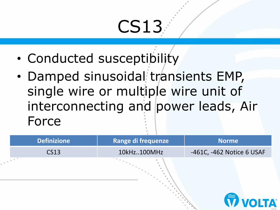
• Conducted susceptibility
• Damped sinusoidal transients EMP, single wire or multiple wire unit of interconnecting and power leads, Air Force
CS13
Definizione Range di frequenze Norme
CS13 10kHz..100MHz -461C, -462 Notice 6 USAF

• Conducted susceptibility
• Bulk Cable Injection
• Pulse modulation: 1kHz 50% duty cycle
CS114
Definizione Range di frequenze Norme
CS114 10kHz..400MHz -461D
CS114 10kHz..200MHz -461E
CS114 (4/)10kHz..200MHz -461F, -461G

Applicazioni MIL-STD-461G CS114
Surface ships A
Submarines A
Aircraft, Army, Including Flight Line A
Aircraft, Navy A
Aircraft, Air Force A
Space systems, Including Launch Vehicles A
Ground, Army A
Ground, Navy A
Ground, Air Force A
Le applicazioni
A: Applicable L: Limited as specified in the individual sections of the standard S: Procuring activity must specify in procurement documentation

• MIL-STD-461G 5.12.1
– This requirement is applicable from 10 kHz to 200 MHz for all interconnecting cables, including power cables. For EUTs intended to be installed on ships or submarines, an additional common mode limit of 77 dBμA is applicable from 4 kHz to 1 MHz on complete power cables (highs and returns - common mode test).
CS114 applicability

• CS114 vs.
– IEC 61000-4-6: Electromagnetic compatibility (EMC) - Part 4-6: Testing and measurement techniques - Immunity to conducted disturbances, induced by radio-frequency fields
MIL-STD-461E-EPS
MIL-STD-461E-EPS:2001

• 6.6.1.1 Frequency Coverage – IEC 61000-4-6 covers the frequency range
from 150kHz to 80MHz. CS114 covers from 10kHz to 200MHz.
– The radiated immunity testing of IEC 61000-4-3 is used above 80MHz to assess performance. MIL-STD-461E recognizes an overlap region between the CS114 conducted susceptibility requirements and the RS103 radiated susceptibility requirements.
MIL-STD-461E-EPS:2001

• 6.6.1.4 Conclusion – IEC 61000-4-6 requirements cover the
most important part of the CS114 frequency range. Differences in test methodology introduce some uncertainty in comparisons. Level 2 of IEC 61000-4-6 is acceptable for Curve 1 of CS114. Level 3 of IEC 61000-4-6 is acceptable for Curve 2 of CS114 and marginally acceptable for Curve 3. Unless a special IEC level is stipulated, no IEC 61000-4-6 certified equipment meets the requirements of Curves 4 and 5 of CS114.
MIL-STD-461E-EPS:2001

• 6.6.2.4 Conclusion
– Section 20 can be substituted for CS114 provided equipment is certified to appropriate limits. Table 6.6-2 shows acceptability of the Section 20 categories as compared to CS114 limit curves.
MIL-STD-461E-EPS:2001

• 5.12.3.2: Test equipment – Measurement receivers – Current injection probes – Current probes – Calibration fixture – Directional couplers – Signal generators – Plotter – Attenuators, 50 – Coaxial load, 50 – Power amplifiers – LISNs
MIL-STD-461G

• 5.12.3.4.b
– Inserire segnale non modulato a 10kHz
– Incrementare il segnale fino al livello di corrente specificato
– Registrare la forward power
– Procedere nella scansione da 10kHz a 200MHz
Integrity check

• 5.12.3.4.c
– Inserire segnale non modulato a 10kHz
– Applicare il livello di forward power definito in 5.12.3.4.b(4) sul range
– Verificare che la foward power segua la calibrazione e che la corrente sia a ±3dB di tolleranza dal limite
Integrity check
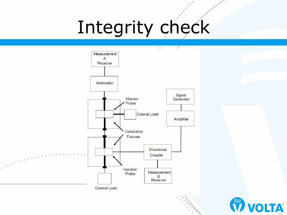
Integrity check

• 5.12.3.4.d
– Azionare l’EUT e lasciarlo stabilizzare
– Regolare il generatore di segnale a 10kHz con 1kHz pulse e 50% duty cycle e verificare i parametri
– Applicare il livello di forward power definito in 5.12.3.4.b(4) alla sonda e controllare la corrente indotta
EUT testing

• 5.7.3.4.c
– Scansire la banda mantenendo il livello di foward power al livello definito in 5.12.3.4.b(4) o il livello massimo di corrente per il limite applicato, quello più stringente dei due
– Per EUT con cablaggio ridondante di sicurezza, usare multi-cable injection technique simultaneamente
EUT testing

EUT testing

• Conducted susceptibility
• Bulk cable injection, impulse excitation
CS115
Definizione Range di frequenze Norme
CS115 Pulse -461D, -461E, -461F, -461G

Applicazioni MIL-STD-461G CS115
Surface ships S
Submarines S
Aircraft, Army, Including Flight Line A
Aircraft, Navy A
Aircraft, Air Force A
Space systems, Including Launch Vehicles A
Ground, Army A
Ground, Navy A
Ground, Air Force A
Le applicazioni
A: Applicable L: Limited as specified in the individual sections of the standard S: Procuring activity must specify in procurement documentation

• MIL-STD-461G 5.13.1
– This requirement is applicable to all aircraft, space, and ground system interconnecting cables, including power cables. The requirement is also applicable for surface ship and submarine subsystems and equipment when specified by the procuring activity.
CS115 applicability
• CS115 vs.
– IEC 61000-4-4: Electromagnetic compatibility (EMC) - Part 4-4: Testing and measurement techniques - Electrical fast transient/burst immunity test
MIL-STD-461E-EPS

MIL-STD-461E-EPS:2001

• 6.7.1.4 Conclusion – While the requirement definitions and test
methodologies for the two requirements are substantially different, similar levels of equipment immunity can be obtained with some confidence by ensuring that equipment is certified to IEC 61000-4-4 at an appropriate level. A comparison that takes into account some limited laboratory experimentation suggests that military equipment normally expected to meet CS115 should be qualified to at least Level 3 of IEC 61000-4-4 to provide reasonable confidence that similar immunity is ensured. The voltage level corresponds to an estimated current of 5.6A compared to the 5.0A of CS115.
MIL-STD-461E-EPS:2001

• 5.13.3.2: Test equipment – Pulse generator, 50, charged line (coaxial) – Current injection probe – Drive cable, 50, 2m, 0.5dB or less
insertion loss 500MHz – Current probe – Calibration fixture – Oscilloscope, 50 input impedance – Attenuators, 50 – Coaxial loads, 50 – LISNs
MIL-STD-461G

• 5.13.3.4.b
– Avviare il generatore di impulsi e incrementare il livello fino alla verifica del livello di corrente necessario attraverso la fixture
– Verificare rise time, fall time e durata dell’impulso
Integrity check

Integrity check
• 5.7.3.4.c
– Azionare l’EUT e lasciarlo stabilizzare
– Applicare il segnale come da verifica con repetition rate e durata da specifiche
– Ripetere per ogni cable bundle che si interfaccia con ogni connettore all’EUT e per i cavi di potenza come da indicazioni
EUT testing

EUT testing

• Conducted susceptibility
• Bulk cable injection, damped sinusoidal transients
CS116
Definizione Range di frequenze Norme
CS116 10kHz..100MHz -461D, -461E, -461F, -461G

Applicazioni MIL-STD-461G CS116
Surface ships A
Submarines L
Aircraft, Army, Including Flight Line A
Aircraft, Navy A
Aircraft, Air Force A
Space systems, Including Launch Vehicles A
Ground, Army A
Ground, Navy A
Ground, Air Force A
Le applicazioni
A: Applicable L: Limited as specified in the individual sections of the standard S: Procuring activity must specify in procurement documentation
• MIL-STD-461G 5.14.1
– This requirement is applicable from 10 kHz to 100 MHz for all interconnecting cables, including power cables, and individual high side power leads. Power returns and neutrals need not be tested individually. For submarine applications, this requirement is applicable only to cables and leads external to or that exit the pressure hull.
CS116 applicability

• CS116 vs. – IEC 61000-4-12: Electromagnetic
compatibility (EMC) - Part 4-12: Testing and measurement techniques - Ring wave immunity test
– IEC 61000-4-25: Electromagnetic compatibility (EMC) - Part 4-25: Testing and measurement techniques - HEMP immunity test methods for equipment and systems
MIL-STD-461E-EPS

MIL-STD-461E-EPS:2001

• 6.8.1.4 Conclusion – Although the test methods are different,
current injection (military) vs voltage injection (commercial), and commercial tests are made at fewer frequencies than the military, the commercial test levels can be more severe than the military. Actual commercial test levels are set by a specification in the individual product, or by a generic, specification. IEC 61000-4-25 provides for very high test levels to evaluate protection against HEMP.
MIL-STD-461E-EPS:2001

• 5.14.3.2: Test equipment – Damped sinusoid transient generator, 100,
charged line (coaxial) – Current injection probe – Drive cable, 50 – Current probe – Calibration fixture – Waveform recording device – Attenuators, 50 – Measurement receivers – Coaxial loads, 50 – LISNs
MIL-STD-461G
• 5.14.3.4.b
– Avviare il generatore a 10kHz e incrementare il livello fino alla verifica del livello di corrente necessario attraverso la fixture
– Verificare rise time, fall time e durata dell’impulso
– Ripetere per ogni frequenza definita dalla norma
Integrity check

Integrity check

• 5.7.3.4.c
– Azionare l’EUT e lasciarlo stabilizzare
– Applicare il segnale a frequenza specificata su ogni cavo
– Ripetere sulle diverse frequenze
EUT testing

EUT testing

• Conducted susceptibility
• Lightning induced transients
• Cable and power leads
CS117
Definizione Range di frequenze Norme
CS117 Pulse -461G

Applicazioni MIL-STD-461G CS117
Surface ships L
Submarines S
Aircraft, Army, Including Flight Line L
Aircraft, Navy L
Aircraft, Air Force L
Space systems, Including Launch Vehicles L
Ground, Army S
Ground, Navy S
Ground, Air Force
Le applicazioni
A: Applicable L: Limited as specified in the individual sections of the standard S: Procuring activity must specify in procurement documentation
• MIL-STD-461G 5.15.1 – This requirement is applicable to all safety-
critical equipment interconnecting cables, including complete power cables, and individual high side power leads. It is also applicable to non-safety critical equipment with interconnecting cables/electrical interfaces that are part of or connected to equipment performing safety critical functions. It may be applicable to equipment performing non-safety critical functions when specified by the procuring activity. This requirement also has limited applicability to surface ship equipment which have cables routed above deck.
CS117 applicability
• 5.15.3.2: Test equipment – Lightning transient generator – Injection transformers – Oscilloscope – Current monitor probes – Attenuators, 50 – Voltage monitor probes, high impedance – Monitor loop, low impedance wire loop – Calibration loop, low impedance wire loop – Capacitor ≥28000F for DC power inputs
– LISNs
MIL-STD-461G

• 5.15.3.4.b – Connettere il generatore all’ingresso
primario del trasformatore di iniezione
– Per ogni forma d’onda ed ogni livello, verificare tensione con anello aperto e corrente con anello in corto e verificare la correttezza dell’impulso
– Per Multiple Stroke e Multiple Burst, verificare anche i tempi e la forma dei treni di impulsi
– Invertire la polarità e ripetere l’operazione
Integrity check

Integrity check

• 5.15.3.4.c – Azionare l’EUT e lasciarlo stabilizzare
– Applicare i transienti fino al livello desiderato e verificare la congruenza
– Per Multiple Stroke, applicare minimo 10 impulsi a distanza non maggiore di 5 minuti uno dall’altro
– Per Multiple Burst, applicare ogni 3 secondi continuativamente per almeno 5 minuti
EUT testing

EUT testing

EUT testing

EUT testing
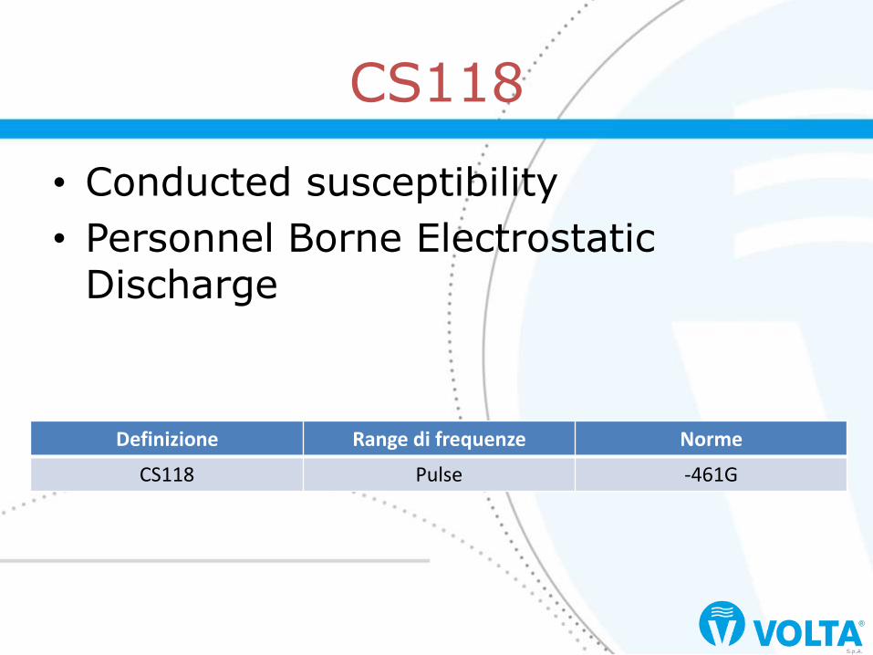
• Conducted susceptibility
• Personnel Borne Electrostatic Discharge
CS118
Definizione Range di frequenze Norme
CS118 Pulse -461G

Applicazioni MIL-STD-461G CS118
Surface ships S
Submarines S
Aircraft, Army, Including Flight Line A
Aircraft, Navy A
Aircraft, Air Force A
Space systems, Including Launch Vehicles
Ground, Army A
Ground, Navy A
Ground, Air Force A
Le applicazioni
A: Applicable L: Limited as specified in the individual sections of the standard S: Procuring activity must specify in procurement documentation

• MIL-STD-461G 5.16.1
– This requirement is applicable to electrical, electronic, and electromechanical subsystems and equipment that have a man-machine interface. It is not applicable to ordnance items.
CS118 applicability

• 5.16.3.2: Test equipment – ESD generator, adjustable from ±2kV to
±15kV – ESD network, 150pF / 330 – Contact and air discharge – Electrostatic voltmeter – Oscilloscope, bandwidth ≥1GHz
– ESD current target – Attenuator 20dB – Coaxial cable, 50 – Metallic ground plane – Ionizer or 1M resistor
MIL-STD-461G

ESD Generator
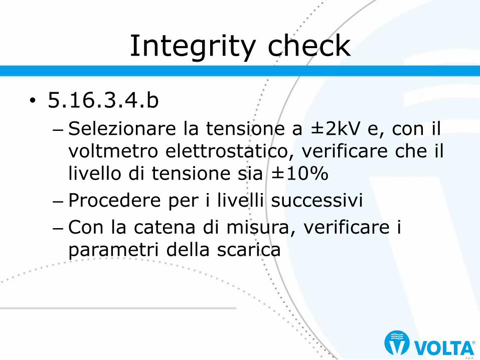
• 5.16.3.4.b
– Selezionare la tensione a ±2kV e, con il voltmetro elettrostatico, verificare che il livello di tensione sia ±10%
– Procedere per i livelli successivi
– Con la catena di misura, verificare i parametri della scarica
Integrity check

Integrity check

Integrity check
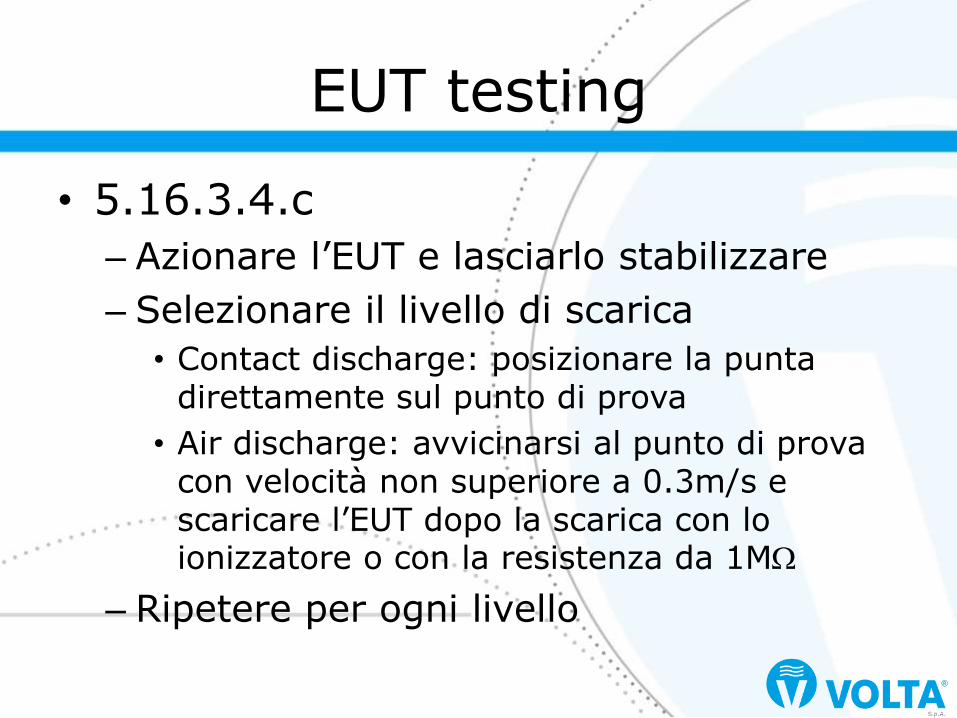
• 5.16.3.4.c
– Azionare l’EUT e lasciarlo stabilizzare
– Selezionare il livello di scarica
• Contact discharge: posizionare la punta direttamente sul punto di prova
• Air discharge: avvicinarsi al punto di prova con velocità non superiore a 0.3m/s e scaricare l’EUT dopo la scarica con lo ionizzatore o con la resistenza da 1M
– Ripetere per ogni livello
EUT testing

EUT Testing

• 5.16.3.3.b – Test Point Selection. The electrostatic
discharges shall be applied to those points and surfaces of the EUT which are accessible to the operator/installer during normal use.
– Test points to be considered shall include the following locations as applicable: any conductive or non-conductive points in the control or keyboard area and any other point of human contact such as switches, knobs, buttons, indicators LEDs, seams slots, grilles, connector shells and other accessible areas. As a minimum, each face shall be included.
EUT testing

EUT Testing