Condition Survey of Assembled Concrete Blocks - · PDF fileCONDITION SURVEY OF ASSEMBLED...
17
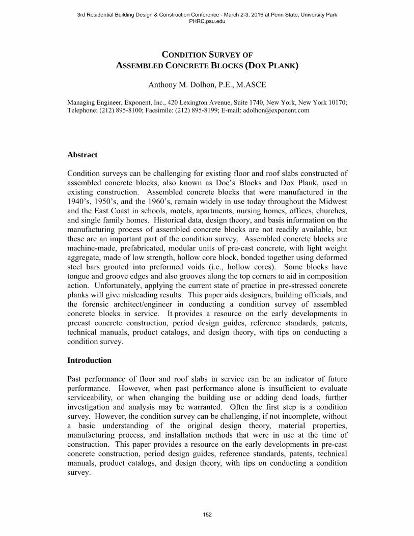
CONDITION SURVEY OF ASSEMBLED CONCRETE BLOCKS (DOX PLANK) Anthony M. Dolhon, P.E., M.ASCE Managing Engineer, Exponent, Inc., 420 Lexington Avenue, Suite 1740, New York, New York 10170; Telephone: (212) 895-8100; Facsimile: (212) 895-8199; E-mail: [email protected] Abstract Condition surveys can be challenging for existing floor and roof slabs constructed of assembled concrete blocks, also known as Doc’s Blocks and Dox Plank, used in existing construction. Assembled concrete blocks that were manufactured in the 1940’s, 1950’s, and the 1960’s, remain widely in use today throughout the Midwest and the East Coast in schools, motels, apartments, nursing homes, offices, churches, and single family homes. Historical data, design theory, and basis information on the manufacturing process of assembled concrete blocks are not readily available, but these are an important part of the condition survey. Assembled concrete blocks are machine-made, prefabricated, modular units of pre-cast concrete, with light weight aggregate, made of low strength, hollow core block, bonded together using deformed steel bars grouted into preformed voids (i.e., hollow cores). Some blocks have tongue and groove edges and also grooves along the top corners to aid in composition action. Unfortunately, applying the current state of practice in pre-stressed concrete planks will give misleading results. This paper aids designers, building officials, and the forensic architect/engineer in conducting a condition survey of assembled concrete blocks in service. It provides a resource on the early developments in precast concrete construction, period design guides, reference standards, patents, technical manuals, product catalogs, and design theory, with tips on conducting a condition survey. Introduction Past performance of floor and roof slabs in service can be an indicator of future performance. However, when past performance alone is insufficient to evaluate serviceability, or when changing the building use or adding dead loads, further investigation and analysis may be warranted. Often the first step is a condition survey. However, the condition survey can be challenging, if not incomplete, without a basic understanding of the original design theory, material properties, manufacturing process, and installation methods that were in use at the time of construction. This paper provides a resource on the early developments in pre-cast concrete construction, period design guides, reference standards, patents, technical manuals, product catalogs, and design theory, with tips on conducting a condition survey. 3rd Residential Building Design & Construction Conference - March 2-3, 2016 at Penn State, University Park PHRC.psu.edu 152
-
Upload
trannguyet -
Category
Documents
-
view
218 -
download
2
Transcript of Condition Survey of Assembled Concrete Blocks - · PDF fileCONDITION SURVEY OF ASSEMBLED...
CONDITION SURVEY OF ASSEMBLED CONCRETE BLOCKS (DOX PLANK)
Anthony M. Dolhon, P.E., M.ASCE
Managing Engineer, Exponent, Inc., 420 Lexington Avenue, Suite 1740, New York, New York 10170; Telephone: (212) 895-8100; Facsimile: (212) 895-8199; E-mail: [email protected]
Abstract
Condition surveys can be challenging for existing floor and roof slabs constructed of assembled concrete blocks, also known as Doc’s Blocks and Dox Plank, used in existing construction. Assembled concrete blocks that were manufactured in the 1940’s, 1950’s, and the 1960’s, remain widely in use today throughout the Midwest and the East Coast in schools, motels, apartments, nursing homes, offices, churches, and single family homes. Historical data, design theory, and basis information on the manufacturing process of assembled concrete blocks are not readily available, but these are an important part of the condition survey. Assembled concrete blocks are machine-made, prefabricated, modular units of pre-cast concrete, with light weight aggregate, made of low strength, hollow core block, bonded together using deformed steel bars grouted into preformed voids (i.e., hollow cores). Some blocks have tongue and groove edges and also grooves along the top corners to aid in composition action. Unfortunately, applying the current state of practice in pre-stressed concrete planks will give misleading results. This paper aids designers, building officials, and the forensic architect/engineer in conducting a condition survey of assembled concrete blocks in service. It provides a resource on the early developments in precast concrete construction, period design guides, reference standards, patents, technical manuals, product catalogs, and design theory, with tips on conducting a condition survey.
Introduction
Past performance of floor and roof slabs in service can be an indicator of future performance. However, when past performance alone is insufficient to evaluate serviceability, or when changing the building use or adding dead loads, further investigation and analysis may be warranted. Often the first step is a condition survey. However, the condition survey can be challenging, if not incomplete, without a basic understanding of the original design theory, material properties, manufacturing process, and installation methods that were in use at the time of construction. This paper provides a resource on the early developments in pre-cast concrete construction, period design guides, reference standards, patents, technical manuals, product catalogs, and design theory, with tips on conducting a condition survey.
3rd Residential Building Design & Construction Conference - March 2-3, 2016 at Penn State, University Park PHRC.psu.edu
152

Background
In the 1920’s, the American Concrete Institute (ACI) formed Committee 711 on the practice and construction methods used in pre-cast concrete joists with superimposed concrete floors and also to make recommendations for minimum standard requirements.
On July 25, 1929, Committee 711 submitted its initial report to ACI. The report was titled, “Precast Joist Concrete Floor Systems.” ACI published its report in January 1940 (ACI 711-1940).
In the 1940’s and 1950’s, assembled concrete blocks gained popularity as an economical alternative to wood and light steel joists for relatively light loads, but were not included in ACI 711 report. Assembled concrete blocks emerged in an effort to eliminate or to minimize the cost of carpentry that was otherwise necessary in formwork used in cast-in-place concrete. They had the advantage of being manufactured in the shop, with greater supervision, quality control, and uniformity than would otherwise be available on the jobsite. They were also well suited for residential and light commercial construction, such as schools, motels, apartments, nursing homes, offices, churches, and single family homes, but were not recommended for roofs or floors with heavy loads or moving machinery due to the potential for impact forces and vibrations.
It wasn’t until November 1952 that Committee 711 introduced standards that were specific to assembled concrete blocks. Manufacturers had already introduced proprietary systems and patents.
By the 1950’s, the subsequent production of high strength steel reinforcement, especially wire strands, and the increased compressive strength of concrete lead to the use of pre-stressed concrete, which improved upon many of the disadvantages of conventionally reinforced concrete. By the late 1960’s, the introduction of pre-cast hollow core, pre-stressed planks captured the market formerly dominated by assembled concrete blocks, which naturally led to their decline and discontinuation.
Plank Description
Assembled concrete blocks are manufactured of lightweight hollow core concrete. They are formed by placing individual blocks end to end in a row to form a plank (Fig. 1). The lightweight aggregate and preformed void space, also known as hollow cores (D), reduced the overall weight of the plank.
Typically, during manufacture the plank is placed upside down on a work table. In some cases, shims (E) may be placed between blocks to form camber within the plank. The blocks within the plank are compressed by an external means using approximately 20,000 pounds of clamping force applied to the ends of the plank. Once the plank is compressed reinforcing steel bars (C) are laid into the aligned
3rd Residential Building Design & Construction Conference - March 2-3, 2016 at Penn State, University Park PHRC.psu.edu
153

channels and grouted into place (B). Once the grout cures, the external means of compression is then removed, thereby forming a minimally pre-stressed plank.
Later variations in the manufacture of planks used tongue and groove edges (A) for shear transfer and longitudinal grooves (F) cast into the upper corners of the blocks to increase composite action, with a thin concrete topping usually up to 2 inches in thickness.
Fig. 1. Typical Assembled Concrete Blocks
Variations in proprietary assembled concrete blocks generally consisted of differences in the external clamping action, grouting process, external tensioning, camber, block shapes, and the manufacturing apparatus. Most of these variations are structurally insignificant and cataloging the variations between proprietary systems is outside of the scope of this paper.
Among the proprietary systems that attracted the most attention was Dox Plank, initially known as “Doc’s Blocks.” It was named for its inventor Mr. Bernard A. “Doc” Vander Heyden, who patented improvements in the planks and
3rd Residential Building Design & Construction Conference - March 2-3, 2016 at Penn State, University Park PHRC.psu.edu
154

in the methods of manufacture in 1954 and 1965. He founded the Dox Plank Manufacturers Association, which licensed approximately 25 manufacturers across the eastern United States in the 1950’s and 1960’s. Although Dox Plank is just one variation on assembled concrete blocks, it came to represent the industry.
Once the planks are delivered to the jobsite, they are able to be hoisted quickly into position and laid side by side to form a floor or roof slab. Once in place the slab served as a working platform. The hollow cores could be used as conduits for utilities or as air ducts. The undersides of the planks formed a flat ceiling which may, or may not, have been plastered.
Standard plank sections were manufactured in 4, 6, 8, and 10 inch depths and 16 inch widths. Planks are designated using a three digit numerical code, followed by a “T” to indicate a topping slab, if present. For example, a standard section 856T indicates an 8 inch deep plank, with 1-No. 5 bar and 1-No. 6 bar and a topping slab.
Patents
On December 14, 1954, Patent No. 2,696,729 was granted to Mr. Vander Heyden for improvements to the manufacture of “pre-stressed” planks using concrete blocks that are supported at their ends (Vander Heyden, 1954). The patent identified 13 claims distinguishing it from other patents using concrete and clay tile block. The patent’s stated objective was,
To provide a strong but light and porous cementitious plank combining great strength with a high thermal and acoustical insulation factor, which together with its light weight, adapts it for making of roofs and floors, and the like.
The patent claims that the manufacturing process provides a means for grinding the face of individual blocks, aligning the channels and also the preformed voids/hollow cores within a row of blocks, using shims between individual blocks to create a camber/arch in the plank, placing reinforcing bars at pre-determined positions in the plank, using reinforcing bars that are not threaded nor do they extend beyond the end blocks, compressing the assembly of blocks, grouting the reinforcing bars while the assembly of blocks remains in compression, grouting the reinforcing bars throughout the length of the plank so as to distribute the compressive stress to individual blocks rather than concentrating it within the end blocks, and transferring compressive stress in the blocks through the bond with the reinforcing bars thereby forming a minimally pre-stressed plank.
On March 9, 1965, Patent No. 3,172,932 was granted to Mr. Vander Heyden for additional improvements to the method of manufacturing a concrete plank. It identified 10 claims pertaining to pre-fabricated or drilled access ports for pressure grouting in special blocks provided at pre-determined intervals along the length of the plank and to provide a step by step process for grouting (Vander Heyden, 1965).
3rd Residential Building Design & Construction Conference - March 2-3, 2016 at Penn State, University Park PHRC.psu.edu
155
Specifications and Design Data
The Dox Plank Manufacturers Association licensed those manufacturers that complied with Patent No. 2,696,729. Each manufacturer produced its own technical manual which included standard specifications, design assumptions, design tables, and installation details (Dox Plank Manufacturers Association, 1960 est.).
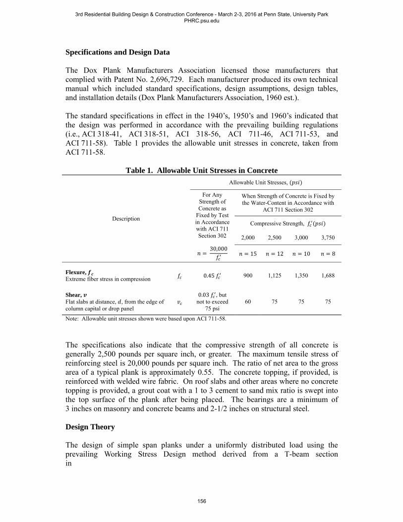
The standard specifications in effect in the 1940’s, 1950’s and 1960’s indicated that the design was performed in accordance with the prevailing building regulations (i.e., ACI 318-41, ACI 318-51, ACI 318-56, ACI 711-46, ACI 711-53, and ACI 711-58). Table 1 provides the allowable unit stresses in concrete, taken from ACI 711-58.
Table 1. Allowable Unit Stresses in Concrete
Description
Allowable Unit Stresses,
For Any Strength of Concrete as
Fixed by Test in Accordance with ACI 711 Section 302
30,000
When Strength of Concrete is Fixed by the Water-Content in Accordance with
ACI 711 Section 302
Compressive Strength,
2,000 2,500 3,000 3,750
15 12 10 8
Flexure, Extreme fiber stress in compression 0.45 900 1,125 1,350 1,688
Shear, Flat slabs at distance, , from the edge of column capital or drop panel
0.03 , but
not to exceed 75 psi
60 75 75 75
Note: Allowable unit stresses shown were based upon ACI 711-58.
The specifications also indicate that the compressive strength of all concrete is generally 2,500 pounds per square inch, or greater. The maximum tensile stress of reinforcing steel is 20,000 pounds per square inch. The ratio of net area to the gross area of a typical plank is approximately 0.55. The concrete topping, if provided, is reinforced with welded wire fabric. On roof slabs and other areas where no concrete topping is provided, a grout coat with a 1 to 3 cement to sand mix ratio is swept into the top surface of the plank after being placed. The bearings are a minimum of 3 inches on masonry and concrete beams and 2-1/2 inches on structural steel.
Design Theory
The design of simple span planks under a uniformly distributed load using the prevailing Working Stress Design method derived from a T-beam section in
3rd Residential Building Design & Construction Conference - March 2-3, 2016 at Penn State, University Park PHRC.psu.edu
156

accordance with the ACI Reinforced Concrete Design Handbook (ACI 317-55) yielded the following standard formula used in the original plank design:
1
1 2
2
3
4
2 15
1.0 23
2 x 6
2 1.0
7
The values of and are illustrated in Fig. 2,
Fig. 2. Stress Diagram
Additional Load Capacity Considerations
Assembled concrete blocks essentially behave as a collection of simply supported beams. The cross section of a typical plank is comparable to a box beam with top and bottom flanges and side web elements.
3rd Residential Building Design & Construction Conference - March 2-3, 2016 at Penn State, University Park PHRC.psu.edu
157

In a plank, the primary flexural compression element (i.e., the bonded concrete topping, if present) and the primary flexural tension element (i.e., the reinforcing bars grouted in the bottom channel openings) are continuous over the entire span length. Thus, the demands sustained by these elements are similar to the demands sustained in a conventional cast-in-place or precast concrete beam, and the flexural capacity of plank can be established using typical flexural design principles. However, plank must be treated differently in shear. This is due to the regular, closely spaced, web discontinuities at the unbonded butt joints between the ends of adjacent planks along the span length. These discontinuities alter the distribution of shear stresses as compared to that which would be sustained in a continuous beam web. Fig. 3 illustrates a free body diagram of a single plank.
Fig. 3. Free Body Diagram
On the cross-section of the plank below Plane A-A' in Fig. 3, the only external forces are the net horizontal force in the reinforcing bar (∆ ) and the small fraction of the total shear taken by the bar at each end (∆ ). Unless the reinforcing bar carries most of the interface shear, which is not realistic, summing the moments about the center of the block will result in significant moment associated with vertical flexural stresses in the web of the plank. If the tensile stress levels are high enough, web failure can compromise plank capacity. In a member with a continuous web, this does not occur.
The presence of significant web tensile stresses of the type shown in Fig. 3 is a characteristic of flexural members with closely spaced web discontinuities. In this manner, the plank is comparable to Sheffield Tile Deck System (Hill, 2003). The magnitude of these tensile stresses relative to the tensile strength of the concrete used to fabricate the plank must be evaluated to establish the true flexural strength of the plank. In some instances, these stress levels will control the ultimate capacity. Although manufacturer load tables given in the Technical Manuals of the Dox Plank catalogs provide guidance regarding the capacity of a plank, their development did not include consideration of the local stress mechanism described above.
3rd Residential Building Design & Construction Conference - March 2-3, 2016 at Penn State, University Park PHRC.psu.edu
158

Therefore, the effect must be evaluated to ensure that the appropriate limiting strength is established.
Use and Application
Assembled concrete blocks were well suited for schools, apartment buildings, nursing homes, offices, churches, and single family homes where load bearing walls are uniformly placed along main corridors and between quest rooms, offices, and classrooms. Figs. 4-7 illustrate typical building construction using planks in the floors and roof systems. At the time of construction, the planks could be quickly placed and serve as cover to the floor below and as a working platform above.
Tips for Conducting a Condition Survey
Based upon the historical data, original design theory, material properties, manufacturing process, and basic installation methods used at the time of manufacture and construction presented above, below are a few tips on conducting a condition survey.
Past surveys of assembled concrete blocks in service reveal that the planks are prone to cracking in the webs (Figs. 8-9); corrosion of embedded steel reinforcing (Figs. 10-11); open joints and the separation between adjacent planks and differential settlement between planks (Figs. 12-13).
Area of Reinforcement: Each plank contains two embedded reinforcing steel bars. These maybe the same diameter or vary by one bar diameter. For example, a single plank may contain 2-No. 5 bars, or 1-No. 5 bar and 1-No. 4 bar, or 1-No. 5 bar and 1-No. 6 bar. These planks are designated 855, 854, or 856, respectively. Therefore, the bar size is not readily known without investigating the size of both bars in each plank.
Conventional Reinforcement: Reinforcement used in assembled concrete blocks is mild steel. The pre-compression forces are of the magnitude of 20,000 pounds with incidental pre-stress force transferred to the reinforcement. Despite the early claims that the assembled concrete blocks are pre-stressed concrete planks, the planks are more accurately conventionally reinforced concrete, with incidental pre-stressing. Applying the current state of practice in pre-stressed concrete planks to assembled concrete blocks will give misleading results.
Simple Span Planks: Assembled concrete blocks were generally intended in simple span construction, with a pair of reinforcing bars at the bottom of the section, and wire mesh in the topping slab. Negative moment bending is contrary to the original design. Therefore, the placement of intermediate partition walls below the planks need to be investigated to determine whether the partition walls engage the planks and provide unintended bearing, which may cause stress reversals.
3rd Residential Building Design & Construction Conference - March 2-3, 2016 at Penn State, University Park PHRC.psu.edu
159

Load Capacity: Original designs of assembled concrete blocks typically used the lightest possible planks to resist the design loads resulting in minimal reserve load capacity. Therefore, subsequent alterations to floors and roofs with assembled concrete blocks need to be investigated to ensure that the planks have sufficient capacity to resist any additional loads.
Lightweight Aggregate: The assembled concrete blocks are made with lightweight aggregate giving the blocks an extremely low modulus of elasticity. Manufacturer’s technical design data indicates that the modulus of elasticity of the block is 1,666,667 pounds per square inch. As with other low modulus concretes, deflection and in particular creep can become problematic. Therefore, the investigation of creep and differential deflection between adjacent planks needs to be investigated.
Water Intrusion: The concrete blocks are touted as being porous in part to improve the acoustical properties of the underside of the plank. However, high porosity is correlated with low resistance to carbonation and low resistance to water penetration. Therefore, the exposure of the concrete blocks to water intrusion from leaks in the roofs, overhangs, and balconies can result in corrosion of the embedded steel reinforcement.
3rd Residential Building Design & Construction Conference - March 2-3, 2016 at Penn State, University Park PHRC.psu.edu
160

Fig. 4. Floors and balconies constructed using assembled concrete blocks.
Fig. 5. Floors of nursing home constructed using assembled concrete blocks.
3rd Residential Building Design & Construction Conference - March 2-3, 2016 at Penn State, University Park PHRC.psu.edu
161

Fig. 6. Floors of offices constructed using assembly concrete blocks.
Fig. 7. Roof of school gymnasium constructed using assembly concrete blocks.
3rd Residential Building Design & Construction Conference - March 2-3, 2016 at Penn State, University Park PHRC.psu.edu
162

Fig. 8. Cracks viewed from within the hollow core.
Fig. 9. Cracks viewed from within the hollow core.
3rd Residential Building Design & Construction Conference - March 2-3, 2016 at Penn State, University Park PHRC.psu.edu
163

Fig. 10. Spalled concrete cover with exposed reinforcement.
Fig. 11. Close-up of corrosion and section loss on exposed reinforcement.
3rd Residential Building Design & Construction Conference - March 2-3, 2016 at Penn State, University Park PHRC.psu.edu
164

Fig. 12. Open joints between adjacent planks (arrow).
Fig. 13. No grout between joints (arrow) and no topping slab.
3rd Residential Building Design & Construction Conference - March 2-3, 2016 at Penn State, University Park PHRC.psu.edu
165

Summary and Concluding Remarks
This paper aids designers, building officials, and the forensic architect/engineer in conducting a condition survey of assembled concrete blocks in service. Notable takeaways include the following:
1. Embedded reinforcing steel bars maybe the same diameter or vary by one bardiameter.
2. Despite the early claims that the assembled concrete blocks are pre-stressedconcrete planks, the planks are more accurately conventionally reinforcedconcrete, with incidental pre-stressing.
3. Assembled concrete blocks were generally intended for simple spanconstruction, and so negative bending over partition walls is generallycontrary to the original design may cause unintended stress reversal andcracking in the negative moment regions.
4. The addition of post-construction topping slabs, flooring, and roof overlays onassembled concrete blocks necessitates the need for an available reservecapacity.
5. Assembled concrete blocks are vulnerable to deflection and creep due to theirlow modulus of elasticity.
6. The condition of an existing topping slab may adversely affect thecomposition action of the plank.
7. The porous nature of assembled concrete blocks make then vulnerable towater intrusion and corrosion of embedded reinforcing steel.
References
American Concrete Institute (1940), Reported by ACI Committee 711. “Precast Joist Concrete Floor Systems.” Proceedings of the American Concrete Institute, Volume 36, Title 36-15, Journal of the American Concrete Institute, January 1940, pp. 297-312.
American Concrete Institute (1945), Reported by ACI Committee 318. ACI Standard, “Building Regulations for Reinforced Concrete (ACI 318-41).” Proceedings of the American Concrete Institute, Volume 41, Title 41-23, Journal of the American Concrete Institute, Volume 16, No. 6, June 1945, pp. 559-619.
3rd Residential Building Design & Construction Conference - March 2-3, 2016 at Penn State, University Park PHRC.psu.edu
166

American Concrete Institute (1946), Reported by ACI Committee 711. ACI Standard, “Minimum Standard Requirements for Precast Concrete Floor Units (ACI 711-46).” Proceedings, American Concrete Institute, Volume 43, Title 43-6, Journal of the American Concrete Institute, Volume 18, No. 2, October 1946, pp. 133-146.
American Concrete Institute (1951), Reported by ACI Committee 318. ACI Standard, “Building Code Requirements for Reinforced Concrete (ACI 318-51).” Proceedings, American Concrete Institute, Volume 47, Title 47-43, Journal of the American Concrete Institute, Volume 22, No. 8, April 1951, pp. 589-652.
American Concrete Institute (1953), Reported by ACI Committee 711. ACI Standard, “Minimum Standard Requirements for Precast Concrete Floor Units (ACI 711-53).” Proceedings, American Concrete Institute, Volume 50, Title 50-1, Journal of the American Concrete Institute, Volume 25, No. 1, September 1953, pp. 1-15.
American Concrete Institute (1955), Reported by ACI Committee 317. Reinforced Concrete Design Handbook, Second Edition 1955.
American Concrete Institute (1956), Reported by ACI Committee 318. ACI Standard, “Building Code Requirements for Reinforced Concrete (ACI 318-56).” Proceedings, American Concrete Institute, Volume 52, Title 52-57, Journal of the American Concrete Institute, Volume 27, No. 9, May 1956, pp. 913-986.
American Concrete Institute (1958), Reported by ACI Committee 711. ACI Standard, “Minimum Standard Requirements for Precast Concrete Floor and Roof Units (ACI 711-58).” Proceedings, American Concrete Institute, Volume 55, Title 55-4, Journal of the American Concrete Institute, Volume 30, No. 1, July 1958, pp. 83-94.
Dox Plank Manufacturers Association (1960), Dox Plank Technical Manual published for Dox Plank of Minnesota, Nabco Plank Company, Baltimore Concrete Plank Corporation, Dox Planks of Northeastern PA, and Dox Block System, 1960 (est.).
Heyden, Bernard A. Vander (1954). “Cementitious Plank and Method of Constructing It.” United States Patent Office, Patent No. 2,696,729, Patented December 14, 1954.
Heyden, Bernard A. Vander (1965). “Method of Manufacturing a Concrete Plank.” United States Patent Office, Patent No. 3,172,932, Patented March 9, 1965.
3rd Residential Building Design & Construction Conference - March 2-3, 2016 at Penn State, University Park PHRC.psu.edu
167

Hill, Howard J. (2003). “Investigation of a Sheffield Structural Tile Floor Failure Indicates a Dangerous Design/Development Oversight.” ASCE Practice Periodical on Structural Design and Construction, Volume 8, Issue 4, November 2003, pp. 190-194.
3rd Residential Building Design & Construction Conference - March 2-3, 2016 at Penn State, University Park PHRC.psu.edu
168