Condensation in Buildings – Tasmanian Designers’ Guide ... · new home designs. However,...
24
Condensation in Buildings – Tasmanian Designers’ Guide - Version 2 Consumer, Building and Occupational Services Department of Justice
Transcript of Condensation in Buildings – Tasmanian Designers’ Guide ... · new home designs. However,...

Condensation in Buildings – Tasmanian Designers’ Guide - Version 2
Consumer, Building and Occupational Services Department of Justice

This Guide is a resource and reference document and is for general information only.
Director of Building Control
Consumer, Building and Occupational Services
April 2019
ISBN 978-0-9954065-8-2
Published April 2019
Consumer, Building and Occupational Services
P 1300 654 499
W www.cbos.tas.gov.au

ContentsIntroduction 5
Scope 5
What causes condensation? 6
Strategies for minimising condensation 8
Roof space 9Main causes of condensation in roof spaces 9
Key ways to minimise condensation in roof spaces 9
Roof reference diagrams 10
Ventilation supply and exhaust 11
Continuous gap 11
Roof vents 11
Pitch 12
Supply vent reference diagrams 13
Exhaust vent reference diagrams 16
Wall 18Key causes of condensation in walls 18
Vapour permeability 18
Limiting air leakage 18
Wall reference diagrams 19
Subfloor 21Causes of condensation 21
Subfloor ventilation 21
Site moisture and drainage 21
Subfloor reference diagrams 21
Acknowledgements 22
Additional information 22
Condensation in Buildings – Tasmanian Designers’ Guide - Version 2 CBOS 4

Condensation in Buildings – Tasmanian Designers’ Guide - Version 2 CBOS 5
Introduction Condensation has emerged as a significant problem in southern Australian homes. Increased energy efficiency requirements have led to the construction of ‘air tight’ buildings. This, combined with a lack of ventilation, traps water vapour in building envelopes. This is a particular problem in cooler climates as the greater difference in internal and external air temperatures causes more water vapour to build up inside homes. Condensation in homes can cause mould growth, structural failure and serious health issues for occupants.
As condensation is a problem in cool climates like Tasmania, CBOS funded research projects on condensation in 2014 and 2017 by the University of Tasmania School of Architecture & Design. The initial research found that condensation is a major issue in Tasmanian buildings, and led to the development of a designers’ guide. The most recent research examined the risk of condensation in wall and roof systems that comply with the National Construction Code. This Guide incorporates the findings of this research, and provides strategies to help minimise the risk. The Guide focuses on principles that can be included in new home designs. However, strategies like roof space ventilation and draft sealing can be implemented in existing homes if necessary.
Scope This Guide must be read in conjunction with the National Construction Code (NCC), which provides the mandatory minimum standards for buildings in Tasmania. The strategies in this Guide exceed the NCC requirements for condensation management, but are strongly recommended to assist in minimising condensation in cool climates like Tasmania.
All example designs in this Guide are diagrammatic only. They are intended to show ventilation, insulation and sarking installation techniques for minimising condensation. Other aspects of the diagrams may not be reflective of all current NCC requirements or construction practices.
Readers are encouraged to review other research reports and guidance documents on minimising condensation, such as the Australian Building Codes Board Handbook on Condensation in Buildings. Links to further reference material are included at the end of this Guide.

Condensation in Buildings – Tasmanian Designers’ Guide - Version 2 CBOS 6
All example designs in this Guide are diagrammatic only.
What causes condensation?All air contains water vapour. The warmer the air, the more water vapour it can hold. Warm air loses water vapour at night as it cools, which can cause fog and condensation on the ground and other surfaces.
For example, when air cools from 21˚C to 13˚C, condensation will form on cooler surfaces. This is why condensation forms on the inside of single glazing and uninsulated bedroom walls.
Why does condensation occur in homes?
There are two main causes of condensation and mould in many homes:
1. thermal bridging
2. too much water vapour in the home.
Thermal bridgingThermal bridges are paths where heat can transfer through walls, ceilings or floors, regardless of insulation. Thermal bridging occurs where a more conductive or poorly insulated material provides a pathway for heat to flow across a thermal barrier.
When the warm air comes into contact with cooler air or cooler surfaces, the loss of energy will cause the water vapour to condense.
When a building is designed or constructed, thermal bridging and air leakage needs to be considered and managed.
Too much water vapour in the homeThe amount of water vapour that accumulates in a building depends on the number of occupants, and the activities they engage in such as dishwashing, showering and cooking. An adult contributes to about 3 litres of water vapour per day being released into the home environment just by breathing.
The main methods to remove water vapour are:
• ventilation
• vapour permeable building fabrics (materials which allow water vapour to pass through them).
Fig. 1. Thermal bridging in roof space
Fig. 2. Thermal bridging in wall space

Condensation in Buildings – Tasmanian Designers’ Guide - Version 2 CBOS 7
All example designs in this Guide are diagrammatic only.
VentilationSome methods of ventilation to manage water vapour in homes include:
• externally vented kitchen rangehood and bathroom extraction fan
• externally ducted flue for gas appliances
• externally ducted exhaust fan for clothes dryer in laundry
• roof space, wall cavity and subfloor ventilation.
Ventilation can assist with removing water vapour from homes. However, it cannot provide all day and year-round water vapour management. Also, ventilation will not remove water vapour trapped within walls. To do this, vapour permeable building fabric is needed.
Vapour permeable building fabricsA vapour permeable building fabric allows water vapour to passively flow into and out of buildings.
Examples of permeable building fabrics:
• plasterboard
• timber
• clay bricks
• some pliable building membranes
Examples of non-permeable building fabrics:
• glass
• aluminium
• steel
• some pliable building membranes
Whilst glass and steel are important building elements, building system choices need to be carefully considered.
Pliable membranes (or building wrap) help seal a building and hold insulation within the wall frame. Vapour permeable building wrap should be used to allow water vapour to escape from wall cavities. Perforated wraps do not have the same permeability properties as breathable wraps.
Fig. 4. Moisture moving into roof space through exhaust fans
Fig. 3. Excess water vapour escaping from a building (plan view)
VentilationVentilation
Exhaustventilation
Supplyventilation
Vapourpermeable
wall
Fig. 5. Moisture moving into walls through openings for services
Around light switch
Underskirting
Between wall and skirting
Around architrave
Under sill
Around ducting for heat pump

Condensation in Buildings – Tasmanian Designers’ Guide - Version 2 CBOS 8
Strategies for minimising condensation
Strategies for owners Strategies for designers and buildersOpen windows during and after showering and when cooking in kitchens
Duct gas appliances, kitchen rangehoods, clothes dryers and bathroom exhaust fans to outside air
Ensure (non-condensing) clothes dryers are ducted to outside air
Consider make up air strategies, for example, undercut doors, install vents
Keep lids on pans during cooking, avoid unnecessary steam production
Control dampness in subfloors and under croft spaces by covering soils with sealed impervious membranes
Don’t store large quantities of fire wood inside the home in unventilated spaces
Use second generation vapour permeable wall wraps (not punched sarkings)
Keep lids on aquariums Consider the use of bonded foil/insulation for roofs, in conjunction with ventilated roof spaces
Dry clothes in rooms that are well ventilated and warm and shut off from the rest of the building
Create air spaces and ventilate cavities where hardboard, cement sheet or other solid materials are used for external wall claddings
Provide increased ventilation to rooms containing spas and saunas and open windows in these rooms more often
Use eaves and soffit vents (with bushfire mesh where required) to vent roof voids
Avoid the use of unflued gas heaters Minimise use of cold surface materials that directly contact with conditioned warm air spaces
Avoid introducing plants or water features into rooms that are not ventilated
Ventilate spaces between cold surface materials and conditioned warm air spaces
Avoid light fittings that allow warm moist air into colder roof spaces by using surface mounted lights or sealed downlights
Habitable rooms under decks will require additional consideration, including ducting gas appliances, kitchen rangehoods, clothes dryers and bathroom exhaust fans to outside air

Condensation in Buildings – Tasmanian Designers’ Guide - Version 2 CBOS 9
Roof space
Main causes of condensation in roof spaces
1. Vapour passing into roof spaces through the ceiling or through exhaust fans which are not externally ducted. This is a particular problem in kitchens and bathrooms.
2. Thermal bridging:
• between roofing and sarking materials
• between sarking and ceiling insulation
• between uninsulated and insulated areas of the ceiling
• from metallic and vented ceiling lamps
3. Lack of ventilation to remove unwanted water vapour
Key ways to minimise condensation in roof spaces• Extraction systems which duct moist air outside the
building
• Installing supply and exhaust ventilation to remove water vapour from roof space
• Moving sarking to underneath battens to minimise thermal bridging
• Ventilating the sarking space
• Using vapour permeable sarking
These methods are demonstrated in the diagrams on the following pages.
Fig. 6.Thermal bridging between roofing and sarking
Fig. 8.Thermal bridging due to lack of insulation around downlight
Fig. 7.Thermal bridging around downlight

Condensation in Buildings – Tasmanian Designers’ Guide - Version 2 CBOS 10
All example designs in this Guide are diagrammatic only.
Thermal bridgingat batten and when sarking touches roof
Roofing and sarkingat the same temperature- cold surfaces at night
Roofing is a cold surface at night. Condensation forms on this surface.
Roofing is a cold surface at night. With ventilation, less condensation forms on this surface and is carried away by sarking.
Condensation formson cold surfaces
Water drips andpools on insulation and interior
Sarking is vapour permeable. Sarking is isolated and less cold than roofing, and with ventilation, minimal condensation forms on this surface.
Ventilated sarking zone reduces condensation on roofing
Ventilated roof space
Fig. 9. Typical roof
Fig. 10. Sarking under battens
Fig. 11. Sarking under battens and ventilation
Moist air is trapped in roof space
Sarking space not vented, but sarking is isolated so less condensation forms
Typical roofNo ventilation. Sarking in contact with roofing causing condensation on cold surfaces.
Sarking under battensInstall sarking underneath battens to minimise thermal bridging
Sarking under battens and ventilationInstall sarking underneath battens to minimise thermal bridging. Ensure ventilation in both sarking zone and roof space. These steps combined will minimise condensation in the roof space.

Condensation in Buildings – Tasmanian Designers’ Guide - Version 2 CBOS 11
Ventilation supply and exhaustThere are three methods to add supply ventilation and exhaust ventilation to roof spaces:
1. continuous gaps
2. regularly spaced vents
3. mechanical ventilation systems
• Use continuous gaps in the eaves or roof vents to provide adequate roof ventilation
• Ensure the defined minimum air space height is maintained along the path between supply and exhaust (see below)
Continuous gapSupply Exhaust
Continuous gap at eaves is: 25mm for <16˚ pitch 10mm for >16˚ pitch
Continuous gap at ridge is at least 5mm for all roof pitches
Roof ventsThe minimum vent area should be:
a) Ceiling area/150 for <16˚ pitch, or
b) Ceiling area/300 for >16˚ pitch
Supply Exhaust
75% of ventilation should be supply
25% of ventilation should be exhaust
Vent at gable should be within 900mm of ridge.
Fig. 12. Continuous eave vent
Fig. 13. Continuous gap in sarking along ridge
Fig. 14. Regularly spaced eave vent
Fig. 15. Regularly spaced gable or parapet vents
Condensation in Buildings – Tasmanian Designers’ Guide - Version 2 CBOS 12
All example designs in this Guide are diagrammatic only.
Lowpitchroof<5˚
Mediumpitchroof>5˚to<16˚
Highpitchroof>16˚
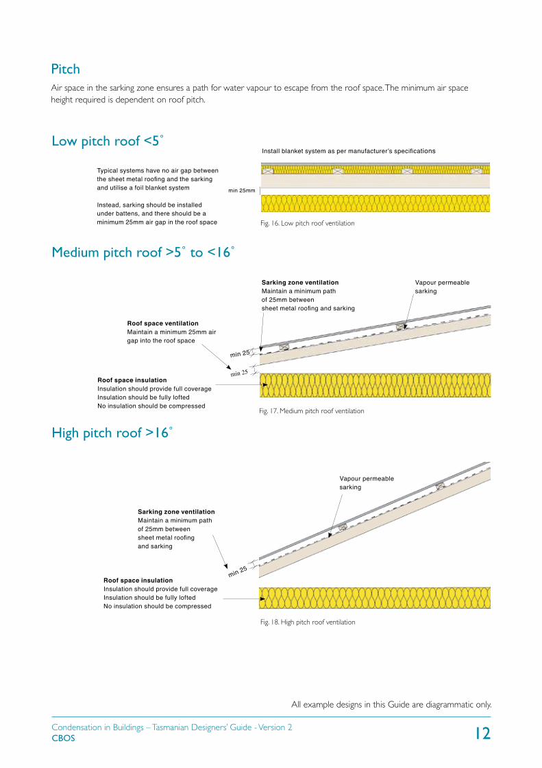
Install blanket system as per manufacturer’s specifications
Vapour permeable sarking
Roof space ventilationMaintain a minimum 25mm air gap into the roof space
min 25
Sarking zone ventilationMaintain a minimum path of 25mm betweensheet metal roofing and sarking
min 25
min 25
Sarking zone ventilationMaintain a minimum path of 25mm betweensheet metal roofing and sarking
Vapour permeable sarking
Fig. 17. Medium pitch roof ventilation
Fig. 18. High pitch roof ventilation
Typical systems have no air gap between the sheet metal roofing and the sarking and utilise a foil blanket system
Instead, sarking should be installed under battens, and there should be a minimum 25mm air gap in the roof space
Roof space insulationInsulation should provide full coverageInsulation should be fully loftedNo insulation should be compressed
Roof space insulationInsulation should provide full coverageInsulation should be fully loftedNo insulation should be compressed
Fig. 16. Low pitch roof ventilation
PitchAir space in the sarking zone ensures a path for water vapour to escape from the roof space. The minimum air space height required is dependent on roof pitch.
min 25mm

Condensation in Buildings – Tasmanian Designers’ Guide - Version 2 CBOS 13
All example designs in this Guide are diagrammatic only.
• For all diagrams, the amount of ventilation required depends on roof pitch (see pages 11 and 12).
• In bushfire-prone areas, ventilation will need to comply with Australian Standard AS 3959:2018 Construction of buildings in bushfire-prone areas. Some of the requirements in this standard for ventilation are shown on diagrams where indicated.
• All example designs in this Guide are diagrammatic only. They are intended to show ventilation, insulation and sarking installation techniques for minimising condensation. Other aspects of the diagrams may not be reflective of all current NCC requirements or construction practices.
Roof insulation
Wall insulationsoffit lining
Maintain requiredair gap distancethroughout the roof cavityRefer to table page 11
Soffit lining
Mesh
Ember resistant steel meshRefer to AS3959
Non combustible compressiblematerialRefer to AS3959
Fig. 19.Typical eaved roof
Fig. 20. Eaved roof with some bushfire considerations shown
Fig. 21. Typical cathedral roof
Sheet metal roofing
Batten
Sarking
Roof structure
Sheet metal roofing
Batten
Sarking
Anti-ponding board
Roof structure
Mesh
Supply vent reference diagrams

Condensation in Buildings – Tasmanian Designers’ Guide - Version 2 CBOS 14
All example designs in this Guide are diagrammatic only.
Ember resistant steel meshRefer to AS3959
Non combustible compressiblematerialRefer to AS3959
Fig. 22. Cathedral roof with some bushfire considerations shown
Eave vent
Fig. 23. Eaved roof with eave vent
Maintain required air gap distancethroughout the roof cavity
Roof insulation extends to cover top plate
Wall insulation
Sheet metal roofingBatten
Sarking
Anti-ponding boardRoof structure
Soffit lining
Ember resistant eave vent Refer to AS3959
Non combustible compressiblematerialRefer to AS3959
Fig. 24. Eaved roof with eave vent with some bushfire considerations shown

Condensation in Buildings – Tasmanian Designers’ Guide - Version 2 CBOS 15
All example designs in this Guide are diagrammatic only.
Non combustible compressiblematerialRefer to AS3959
Fig. 25. Eave vent
Fig. 26. Eave vent with some bushfire considerations shown
Sheet metal
BattenPonding plank and sarking
Roof structure
Parapet cap/flashing
Internal gutter
Vent must be above insulation
Ember resistant vent Refer to AS3959

Condensation in Buildings – Tasmanian Designers’ Guide - Version 2 CBOS 16
Exhaust vent reference diagrams
Vent must be within 900mm from ridge cap
Non combustible compressiblematerialRefer to AS3959
Ember resistant gable vent Refer to AS3959
Ember resistant steel meshRefer to AS3959
Non combustible compressiblematerialRefer to AS3959
Fig. 27. Ridge cap continuous gap
Fig. 28. Ridge cap continuous gap with some bushfire considerations shown
Fig. 29. Gable vent
Fig. 30. Gable vent with some bushfire considerations shown
Ridge cap
Sheet metal roofing
Batten
Roof structure
Sarking
Ridge cap
Sheet metal roofing
Batten
Roof structure
Sarking
Gable vent
• For all diagrams, the amount of ventilation required depends on roof pitch (see pages 11 and 12).
• In bushfire-prone areas, ventilation will need to comply with AS3959. Some of the requirements in this standard for ventilation are shown on diagrams where indicated.
All example designs in this Guide are diagrammatic only.

Condensation in Buildings – Tasmanian Designers’ Guide - Version 2 CBOS 17
All example designs in this Guide are diagrammatic only.
Vent must be within 900mm from top edge
Vent must be within 900mm from top edge
Ember resistant vent Refer to AS3959
Non combustible compressiblematerial Refer to AS3959
Ember resistant eave vent Refer to AS3959
Non combustible compressiblematerial Refer to AS3959
Fig. 31.Typical cathedral vent
Fig. 32. Cathedral vent with some bushfire considerations shown
Fig. 33. Parapet vent
Fig. 34. Parapet vent with some bushfire considerations shown
Sheet metal roofingBatten
Sarking
Roof structure
Eave vent
Soffit lining
Vent must be above insulation
Flashing
Sheet metal roofing
SarkingC section batten

Condensation in Buildings – Tasmanian Designers’ Guide - Version 2 CBOS 18
Walls
Key causes of condensation in wallsThe key causes of condensation in walls are:
• vapour impermeable pliable wall membranes (building wrap), paints or wall coverings
• thermal bridging
• air leakage.
Vapour impermeable wall elements trap moisture inside the wall cavity, which causes moisture to build up when temperatures cool.
Thermal bridging occurs where a more conductive or poorly insulated material provides a pathway for heat to flow across a thermal barrier such as steel penetrations through insulation.
Air leakage can occur at the top and bottom of pliable wall membranes, in service penetrations and at the edges of walls and in corners where a building envelope is poorly constructed.
Vapour permeabilityTo ensure that water vapour can freely and passively leave the building, all materials which are combined to make an external wall should be vapour permeable.
This includes internal finishes, internal linings, wall insulation and pliable wall membranes.
If a cladding system is in direct contact with the pliable wall building membrane, condensation and subsequent mould growth may occur inside the wall. To avoid this, a vented vapour cavity should be designed and constructed between the vapour permeable pliable building membrane and the external cladding.
Limiting air leakageTo limit air leakage, pliable building membranes should be installed in a way which ensures there is no path for air to escape at the top and bottom of walls.
All joins in the pliable membrane and all penetrations for services, doors and windows, should be sealed to limit air leakage. One way this can be achieved is by taping them with a durable tape.
In new buildings, a pressurisation test can be completed when the doors, windows and membrane is installed to ensure there is no unwanted air leakage.
Fig. 35. Vapour impermeable building wrap traps water vapour in walls
Fig. 36. Mould and rot in wall structure caused by air leakage

Condensation in Buildings – Tasmanian Designers’ Guide - Version 2 CBOS 19
All example designs in this Guide are diagrammatic only.
Minimum vapour cavity width 10mmInsulated wallVapour permeable pliable wall membraneCladding (ensure airflow with spacers to battens)Insulated subfloor structure
Subfloor cladding BattenFor BAL:Fire retardant compressible material (refer to AS3959)Ember resistant steel mesh(refer to AS3959)
Minimum vapour cavity width 10mm Insulated wallVapour permeable pliablewall membraneCladdingInsulated subfloor structure
Subfloor claddingFor BAL:Fire retardant compressible material (refer to AS3959)
Ember resistant steel mesh (refer to AS3959)
Minimum vapour cavity width 10mmInsulated wall Rigid insulationVapour permeable pliable wall membraneCladdingInsulated subfloor structure
Batten For BAL: Fire retardant compressible material (refer to AS3959)
Ember resistant steel mesh (refer to AS3959)
Fig. 37. Suspended timber floor with horizontal battens
Fig. 38. Suspended timber floor with vertical battens
Fig. 39. Suspended timber floor horizontal battens and rigid insulation
• In bushfire-prone areas, ventilation will need to comply with AS3959. Some of the requirements in this standard for ventilation are shown on diagrams where indicated.

Condensation in Buildings – Tasmanian Designers’ Guide - Version 2 CBOS 20
All example designs in this Guide are diagrammatic only.
Minimum vapour cavity width 10mm Insulated stud wall
Vapour permeable pliablewall membraneCladding
BattenFor BAL:Fire retardant compressible material (refer to AS3959)Ember resistant steel mesh (refer to AS3959)
Concrete slab floor
Minimum vapour cavity width 10mm
Insulated stud wall
Vapour permeable pliablewall membraneCladding
For BAL:Fire retardant compressible material (refer to AS3959)Ember resistant steel mesh (refer to AS3959)
Minimum vapour cavity width 10mm Insulated stud wallRigid insulationVapour permeable pliable wall membraneCladding
For BAL:Fire retardant compressible material (refer to AS3959)Ember resistant steel mesh (refer to AS3959)
Fig. 40. Concrete floor horizontal battens
Fig. 41. Concrete floor with vertical battens
Fig. 42. Concrete floor with horizontal battens with rigid insulation
Concrete slab floorFibre cement sheet
Concrete slab floorFibre cement sheet

Condensation in Buildings – Tasmanian Designers’ Guide - Version 2 CBOS 21
All example designs in this Guide are diagrammatic only.
Subfloor
Fig. 44. Subfloor vents in clad wall
Fig. 43. Evenly spaced subfloor vents in masonry wall
Subfloor cladding Footing
Subfloor structure
Subfloor ventFor BAL: Ember resistant subfloor vent (refer to AS3959)
Causes of condensationThere are three main causes of excessive moisture and mould growth in subfloors:
1. non-compliant subfloor ventilation
2. excessive ground moisture from a lack of site drainage
3. excessive ground moisture from water table.
SubfloorventilationThe National Construction Code (NCC) prescribes minimum subfloor ventilation rates for housing with a platform floor. This required ventilation must be applied to all enclosed perimeter platform floored buildings.
Some urban locations may have limited access to ground level cross ventilation. In these cases, the NCC ventilation requirement should be exceeded.
When extending a building, consideration should be given to whether additional subfloor vents are needed. Additional subfloor vents may also be needed where new external paving could affect existing subfloor ventilation.
Site moisture and drainageSite planning and site drainage are critical components of the design and construction of new buildings. The NCC and Australian Standard AS 2870:2011 Residential slabs and footings describe how site drainage should be designed and constructed for new housing. The same principles apply to non-residential buildings.
If a home has excessive subfloor moisture, more appropriate site drainage should be the first action. If subfloor moisture persists, the ground can be covered with a layer of sand.
Fig. 45. Subfloor vents

Condensation in Buildings – Tasmanian Designers’ Guide - Version 2 CBOS 22
AcknowledgementsThe content of this Guide was prepared by Dr Mark Dewsbury with the assistance of Abdel Soudan, Freya Su, Dr Detlev Geard, Anna Cooper, Dr Tim Law, School of Architecture & Design, University of Tasmania.
Additional informationCondensation risk mitigation for Tasmanian housing http://ecite.utas.edu.au/126292
Renovating a pre-1980s weatherboard home: what about condensation? http://ecite.utas.edu.au/122563
Temperate climates, warmer houses and built fabric challenges http://ecite.utas.edu.au/124706
Recent increases in the occurrence of condensation and mould within new Tasmanian housing http://ecite.utas.edu.au/112429
Investigation of destructive condensation in Australian cool-temperate buildings http://ecite.utas.edu.au/108742
Condensation scoping study completed for the Australian Building Codes Board https://www.abcb.gov.au/Resources/Publications/Research/Scoping-Study-of-Condensation-in-Residential-Buildings
Condensation in buildings non-mandatory handbook published by the Australian Building Codes Board https://www.abcb.gov.au/Resources/Publications/Education-Training/Condensation-in-Buildings