
Concrete Pavement Preservation: Lessons Learned …...2019/10/25 · 17 a summary of lessons...
21
Concrete Pavement Preservation: Lessons Learned from 11 Case Studies Prashant Ram, P.E*. (corresponding author) Pavement Engineer Applied Pavement Technology, Inc. (APTech) 115 W. Main St. Suite 400, Urbana, IL 61801, USA [email protected] Jeff Stempihar, Ph.D., P.E. Senior Engineer NCE 14988 N. 78 th Way, Suite 100, Scottsdale, AZ 85260, USA Tom Van Dam, Ph.D., P.E. Principal NCE 1500 E. Tropicana Ave, Suite 178, Las Vegas, NV 89119 Mark B. Snyder President and Manager Pavement Engineering and Research Consultants, LLC (PERC) 7085 Highland Creek Drive, Bridgeville, PA 15017 Kurt D. Smith, P.E. Program Director Applied Pavement Technology, Inc. (APTech) 115 W. Main St. Suite 400, Urbana, IL 61801, USA Tom Yu Program Manager, Pavement Design Federal Highway Administration, Office of Preconstruction, Construction, and Pavements 1200 New Jersey Ave, SE, Washington, DC 20590 KEYWORDS: concrete pavement, concrete pavement restoration, preservation, long-life concrete pavement, maintenance and rehabilitation Conflict of Interest: None Number of figures: 5 x 250 = 1250 words; Number of tables: 3 x 250 = 750; Text: 4950 words. Total Word Count = 6,950 words
Transcript of Concrete Pavement Preservation: Lessons Learned …...2019/10/25 · 17 a summary of lessons...
Concrete Pavement Preservation: Lessons Learned from 11 Case Studies
Prashant Ram, P.E*. (corresponding author) Pavement Engineer Applied Pavement Technology, Inc. (APTech) 115 W. Main St. Suite 400, Urbana, IL 61801, USA [email protected]
Jeff Stempihar, Ph.D., P.E. Senior Engineer NCE 14988 N. 78th Way, Suite 100, Scottsdale, AZ 85260, USA
Tom Van Dam, Ph.D., P.E. Principal NCE 1500 E. Tropicana Ave, Suite 178, Las Vegas, NV 89119
Mark B. Snyder President and Manager Pavement Engineering and Research Consultants, LLC (PERC) 7085 Highland Creek Drive, Bridgeville, PA 15017
Kurt D. Smith, P.E. Program Director Applied Pavement Technology, Inc. (APTech) 115 W. Main St. Suite 400, Urbana, IL 61801, USA
Tom Yu Program Manager, Pavement Design Federal Highway Administration, Office of Preconstruction, Construction, and Pavements 1200 New Jersey Ave, SE, Washington, DC 20590
KEYWORDS: concrete pavement, concrete pavement restoration, preservation, long-life concrete pavement, maintenance and rehabilitation
Conflict of Interest: None
Number of figures: 5 x 250 = 1250 words; Number of tables: 3 x 250 = 750; Text: 4950 words. Total Word Count = 6,950 words
1
1. ABSTRACT 1 2 An ongoing FHWA project is redefining concrete pavement preservation as “preserving the 3 existing concrete pavement structure to extend its service life for as long as possible, by 4 arresting, greatly diminishing, or avoiding the pavement deterioration process.” This can be 5 achieved through three fundamental approaches: (a) designing and constructing pavements that 6 remain structurally adequate and relatively distress-free throughout their service lives (i.e., using 7 long-life concrete pavement), (b) using asphalt or concrete overlays as preservation treatments to 8 maintain the functional performance of the pavement, and (c) maintaining the serviceability of 9 the pavement using concrete pavement restoration (CPR) treatments. 10
One of the tasks under the project was to document 11 concrete pavement projects around the 11 U.S. that have successfully demonstrated the application of the three fundamental preservation 12 approaches mentioned above. This includes information on the following: (a) original pavement 13 design, materials, and construction, (b) traffic and service conditions, (c) maintenance and 14 rehabilitation history, (d) present day condition [based on site visits in 2018], and (e) economic 15 analysis. This paper highlights key information for 11 different case study projects and presents 16 a summary of lessons learned from each project. The information gleaned from these success 17 stories are being used in the development of guidelines for long-term concrete pavement 18 preservation strategies. 19
20
Abstract Word Count: 206 words. 21
22
2
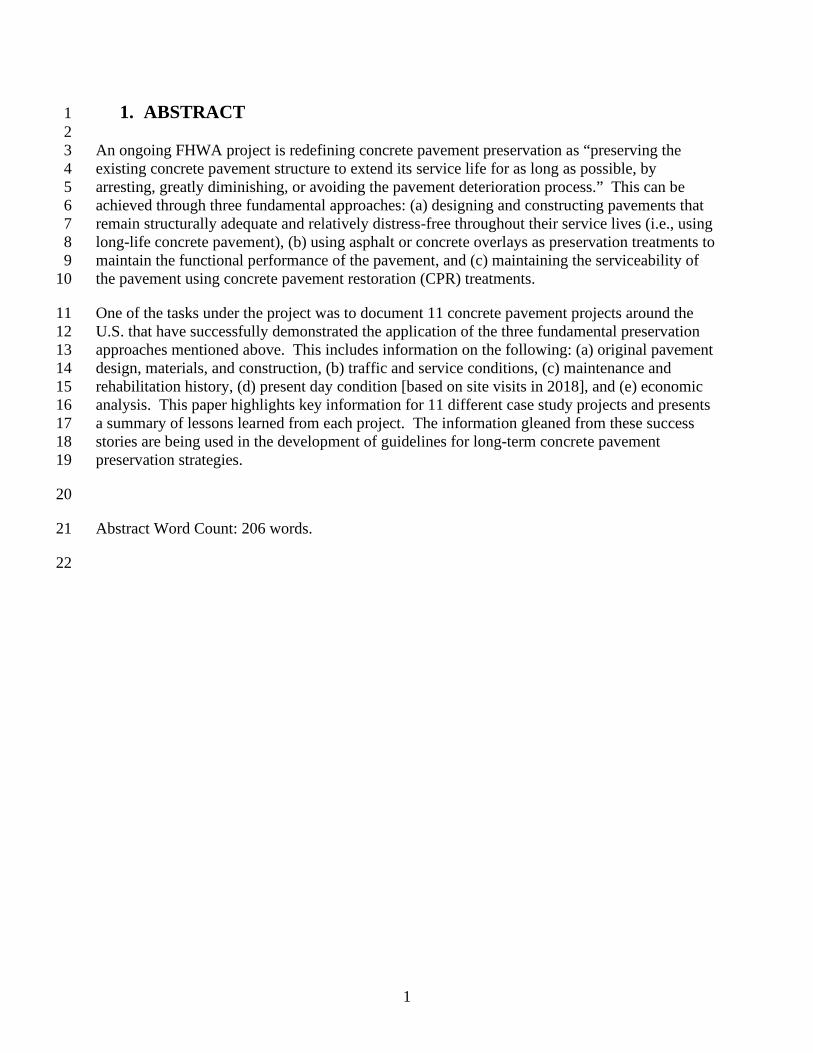
2. INTRODUCTION 1 2 Pavement preservation is a recognized strategy to cost-effectively maintain the serviceability of a 3 pavement and extend its life. According to the Federal Highway Administration (FHWA) 4 Pavement Preservation Expert Task Group (ETG), and as defined in the Moving Ahead for 5 Progress in the 21st Century Act (MAP-21), pavement preservation employs a network-level, 6 long-term strategy that enhances pavement performance by using an integrated, cost-effective set 7 of practices (Geiger 2005). As shown in figure 1, this can be accomplished through preventive 8 maintenance and minor rehabilitation activities that are designed to restore pavement 9 functionality and extend pavement life without necessarily increasing structural capacity (Smith 10 et al. 2014). However, it is recognized that the application of these preventive maintenance and 11 minor rehabilitation treatments to pavements undergoing structural deterioration or materials 12 degradation is, at best, a stop-gap measure that is merely delaying their ultimate failure. It is 13 more desirable to apply preventive maintenance and preservation treatments to pavements that 14 are (and are expected to remain) structurally adequate and durable (Van Dam et al. 2019). 15
16 Figure 1. Pavement preservation activities and pavement condition (Smith et al. 2014) 17
Long service life is a hallmark of concrete pavements, and it is not uncommon for them to 18 provide outstanding performance for 40 or more years. Such extended performance periods are 19 easily achievable by concrete pavements when they employ durable materials and are properly 20 designed and constructed. Throughout their service lives, these pavements will not require any 21 significant rehabilitation other than the timely application of appropriate preservation treatments 22 to maintain their functionality (e.g., smoothness, friction, quietness). When applied to the right 23 concrete pavement at the right time, appropriate preservation strategies can be extremely 24 successful at cost-effectively maintaining functionality and extending service life for 50 years or 25 more (Van Dam et al. 2019). 26
3
The common approach today is to design concrete pavements with the expectation that they will 1 develop structural distress (e.g., slab cracking and joint faulting) within a relatively short time 2 frame (e.g., 20 years), triggering the need for full-depth repairs, diamond grinding, slab 3 stabilization, and other treatments to maintain their serviceability. Thus, the application of 4 maintenance treatments and minor rehabilitation are not used to “preserve” the pavement 5 structure, but instead are applied to concrete pavements that are already suffering structural 6 distresses and other deficiencies to extend the service life for a relatively short amount of time. 7 Although such treatments restore functionality in the short-term, they often do not address the 8 underlying causes of the problems, so the performance of the pavement continues a downward 9 spiral toward inevitable major rehabilitation or reconstruction (Van Dam et al. 2019). 10
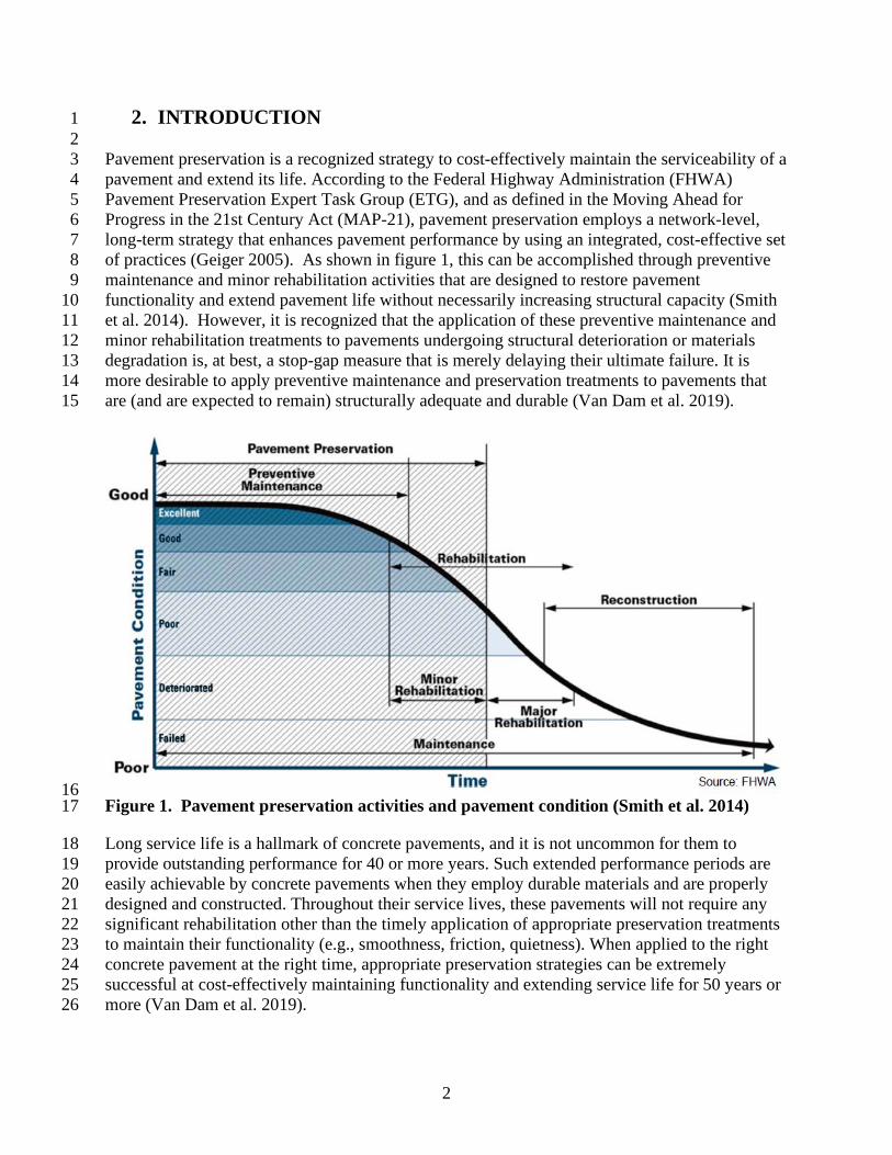
An ongoing FHWA project is redefining concrete pavement preservation as “preserving the 11 existing concrete pavement structure to extend its service life for as long as possible, by 12 arresting, greatly diminishing, or avoiding the pavement deterioration process.” This can be 13 achieved through three fundamental approaches: (a) designing and constructing pavements that 14 remain structurally adequate and relatively distress-free throughout their service lives (i.e., using 15 long-life concrete pavement), (b) using asphalt or concrete overlays as preservation treatments to 16 maintain the functional performance of the pavement, and (c) maintaining the serviceability of 17 the pavement using CPR treatments (Van Dam et al., 2019). Eleven concrete pavement projects 18 around the U.S. (see figure 2) that have successfully demonstrated the application of the three 19 fundamental preservation approaches mentioned above are described in the next section, 20 presented by preservation approach. 21
22
Figure 2. Field project locations. 23
4
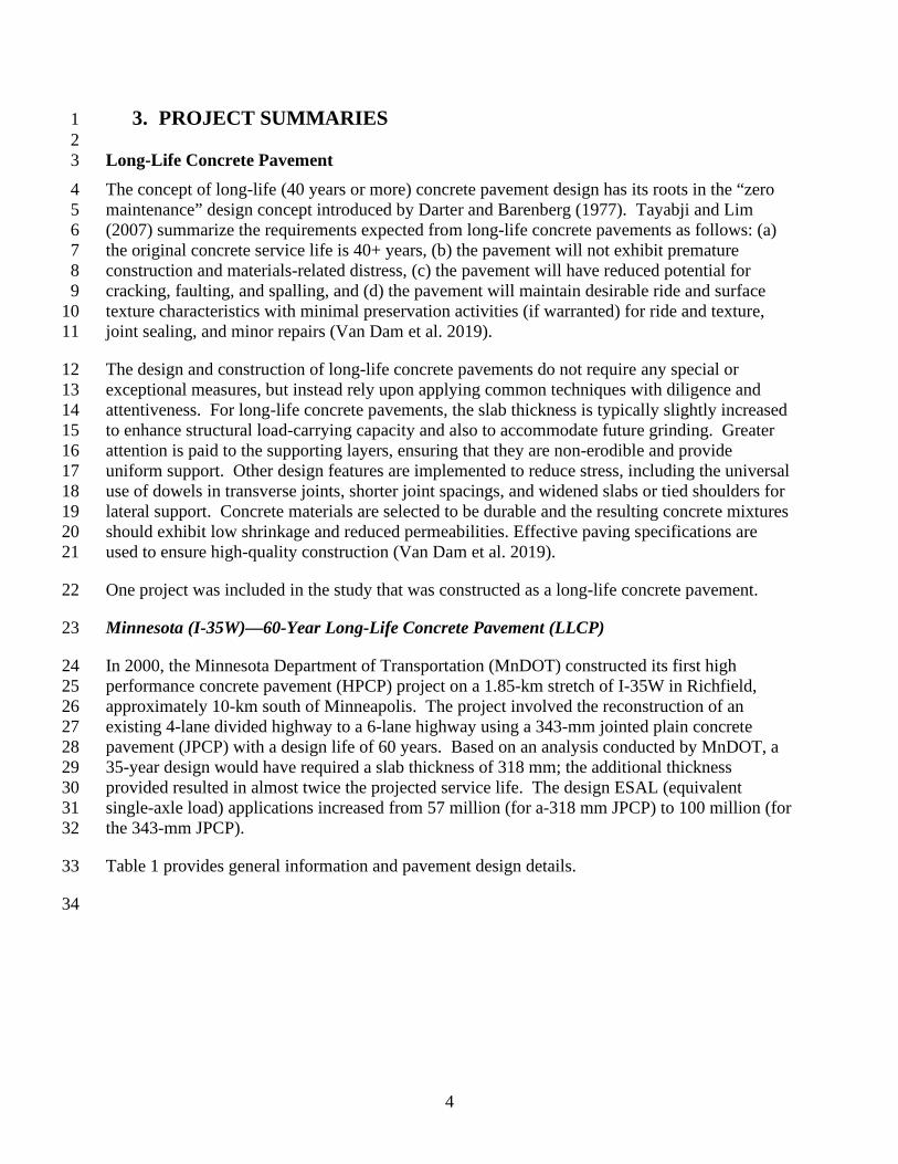
3. PROJECT SUMMARIES 1 2 Long-Life Concrete Pavement 3 The concept of long-life (40 years or more) concrete pavement design has its roots in the “zero 4 maintenance” design concept introduced by Darter and Barenberg (1977). Tayabji and Lim 5 (2007) summarize the requirements expected from long-life concrete pavements as follows: (a) 6 the original concrete service life is 40+ years, (b) the pavement will not exhibit premature 7 construction and materials-related distress, (c) the pavement will have reduced potential for 8 cracking, faulting, and spalling, and (d) the pavement will maintain desirable ride and surface 9 texture characteristics with minimal preservation activities (if warranted) for ride and texture, 10 joint sealing, and minor repairs (Van Dam et al. 2019). 11
The design and construction of long-life concrete pavements do not require any special or 12 exceptional measures, but instead rely upon applying common techniques with diligence and 13 attentiveness. For long-life concrete pavements, the slab thickness is typically slightly increased 14 to enhance structural load-carrying capacity and also to accommodate future grinding. Greater 15 attention is paid to the supporting layers, ensuring that they are non-erodible and provide 16 uniform support. Other design features are implemented to reduce stress, including the universal 17 use of dowels in transverse joints, shorter joint spacings, and widened slabs or tied shoulders for 18 lateral support. Concrete materials are selected to be durable and the resulting concrete mixtures 19 should exhibit low shrinkage and reduced permeabilities. Effective paving specifications are 20 used to ensure high-quality construction (Van Dam et al. 2019). 21
One project was included in the study that was constructed as a long-life concrete pavement. 22
Minnesota (I-35W)––60-Year Long-Life Concrete Pavement (LLCP) 23
In 2000, the Minnesota Department of Transportation (MnDOT) constructed its first high 24 performance concrete pavement (HPCP) project on a 1.85-km stretch of I-35W in Richfield, 25 approximately 10-km south of Minneapolis. The project involved the reconstruction of an 26 existing 4-lane divided highway to a 6-lane highway using a 343-mm jointed plain concrete 27 pavement (JPCP) with a design life of 60 years. Based on an analysis conducted by MnDOT, a 28 35-year design would have required a slab thickness of 318 mm; the additional thickness 29 provided resulted in almost twice the projected service life. The design ESAL (equivalent 30 single-axle load) applications increased from 57 million (for a-318 mm JPCP) to 100 million (for 31 the 343-mm JPCP). 32
Table 1 provides general information and pavement design details. 33
34
5
Table 1. I-35W project details. 1
Key Information Data
Project Location I-35W NB/SB, Richfield, MN; Milepost 9.127 to 10.276; 6-lane divided freeway
Climatic Region Wet-freeze
Initial Construction Year 2000
Rehabilitation Types, Years, and Details
No contracted maintenance or rehabilitation since construction. Minor CPR: Diamond grinding and joint repair is planned for 2020.
Traffic Data (Design) • 1999: AWDT (Average Weekday Daily Traffic): 118,800 • 2019 AWDT: 156,240 (predicted)
Slab Design Details
• 343 mm JPCP • 4.6-m transverse joint spacing • Dowels used on mainline pavement:
- 38 mm diameter, 457 mm long solid stainless steel - 45 mm diameter, 457 mm long stainless steel clad - 38 mm diameter, 457 mm long stainless steel clad
Base/Subbase 102 mm dense-graded granular base 305 mm select granular subbase
Subgrade Existing sandy base course, several feet thick
Subdrainage No open-graded base or edge drains included in design
Shoulder Type and Design
343 mm JPCP 4.6-m transverse joint spacing; Variable width Dowels: 38 mm diameter, 457 mm long plastic-coated
2
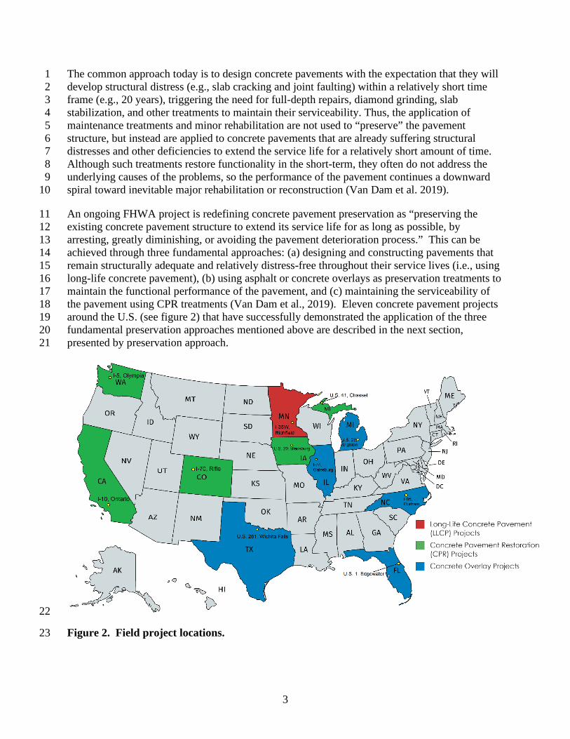
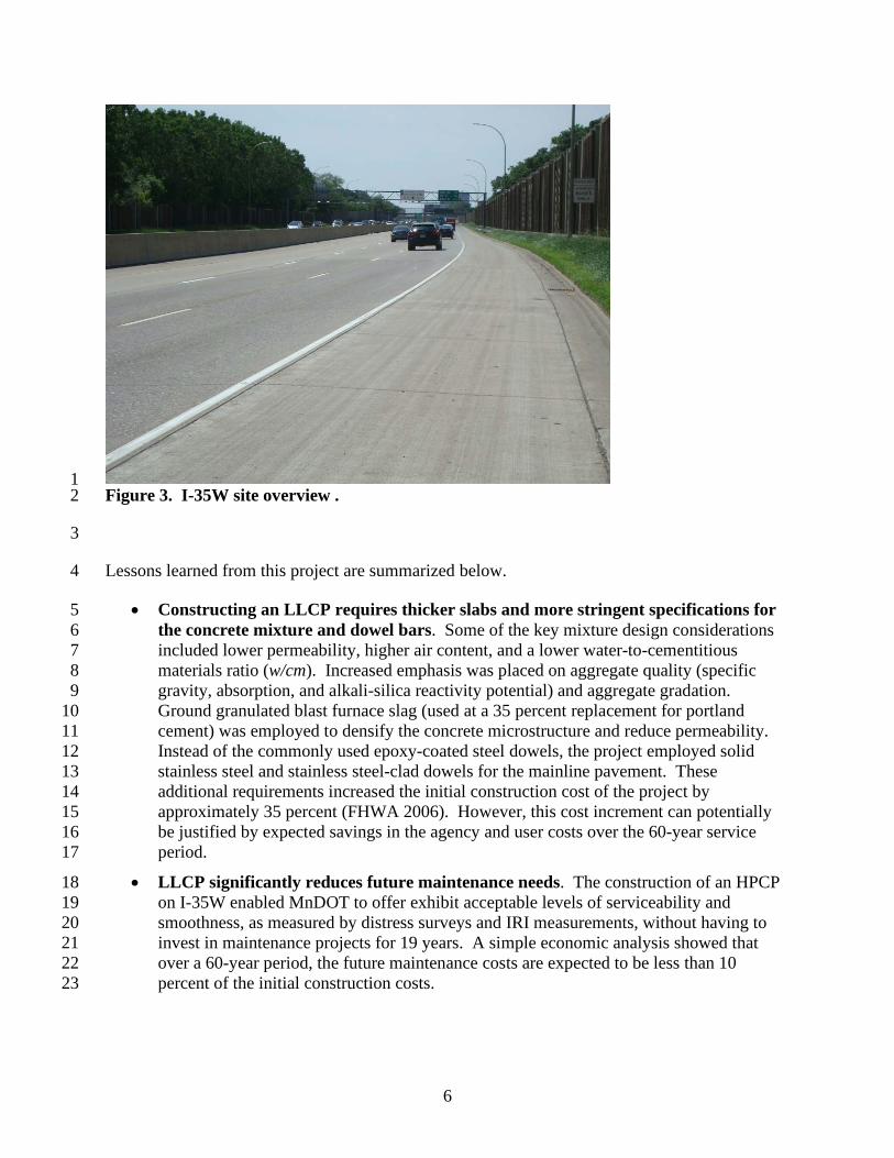
A field visit during the summer of 2018 revealed that the entire section is still in generally good 3 condition, with sporadic presence of joint and corner deterioration, with temporary patching to 4 address some of these distresses. The joint sealant appeared to be missing or damaged at a few 5 locations. Figure 3 shows presents some photographs of the I-35W project. 6
7
6
1 Figure 3. I-35W site overview . 2
3
Lessons learned from this project are summarized below. 4
• Constructing an LLCP requires thicker slabs and more stringent specifications for 5 the concrete mixture and dowel bars. Some of the key mixture design considerations 6 included lower permeability, higher air content, and a lower water-to-cementitious 7 materials ratio (w/cm). Increased emphasis was placed on aggregate quality (specific 8 gravity, absorption, and alkali-silica reactivity potential) and aggregate gradation. 9 Ground granulated blast furnace slag (used at a 35 percent replacement for portland 10 cement) was employed to densify the concrete microstructure and reduce permeability. 11 Instead of the commonly used epoxy-coated steel dowels, the project employed solid 12 stainless steel and stainless steel-clad dowels for the mainline pavement. These 13 additional requirements increased the initial construction cost of the project by 14 approximately 35 percent (FHWA 2006). However, this cost increment can potentially 15 be justified by expected savings in the agency and user costs over the 60-year service 16 period. 17
• LLCP significantly reduces future maintenance needs. The construction of an HPCP 18 on I-35W enabled MnDOT to offer exhibit acceptable levels of serviceability and 19 smoothness, as measured by distress surveys and IRI measurements, without having to 20 invest in maintenance projects for 19 years. A simple economic analysis showed that 21 over a 60-year period, the future maintenance costs are expected to be less than 10 22 percent of the initial construction costs. 23
7
Concrete Pavement Restoration 1
Over the last 40 years or so, CPR has been used to effectively improve the performance and 2 extend the service life of concrete pavements. CPR refers to a host of concrete pavement 3 treatments that are combined, as needed, to improve the performance of an existing concrete 4 roadway (Smith 2005, Smith et al. 2014). Examples of common CPR treatments include joint 5 resealing, slab stabilization, partial-depth repairs, full-depth repairs, dowel bar retrofit, and 6 diamond grinding and grooving. 7 CPR is considered a more cost-effective option in areas with localized distress that would benefit 8 from targeted improvements rather than receiving an overlay over the entire project (ACPA 9 1997). CPR can be used to address the underlying mechanisms of the distress (and not just the 10 symptoms), thus providing for improved performance. And when diamond grinding is performed 11 as part of the CPR operation, the functional service of the pavement can be quickly and 12 effectively restored. 13 CPR can be the most economical solution for long-term concrete pavement preservation if the 14 existing pavement is in sound structural condition and free of materials-related distresses 15 (MRD), such as D-cracking or alkali-silica reactivity (ASR). If this is the case, non-invasive 16 CPR preservation strategies can often be employed with minimal disruption to traffic to maintain 17 pavement functionality for 50 years or more from the time of original construction. 18
However, when a concrete pavement is undergoing structural deterioration that cannot be 19 slowed, CPR may not be the best strategy; a global treatment (such as a structural overlay or 20 reconstruction) may provide the most cost-effective, long-term preservation approach. In such 21 cases, the use of CPR may be appropriate as a “stop-gap” measure to temporarily maintain 22 serviceability until the long-term strategy can be developed and implemented. 23
A total of five CPR projects were evaluated in the study, as described in the following sections. 24 Table 2 provides a general summary of those five CPR projects and figure 4 presents some 25 photographs from each of the projects. 26
27
8
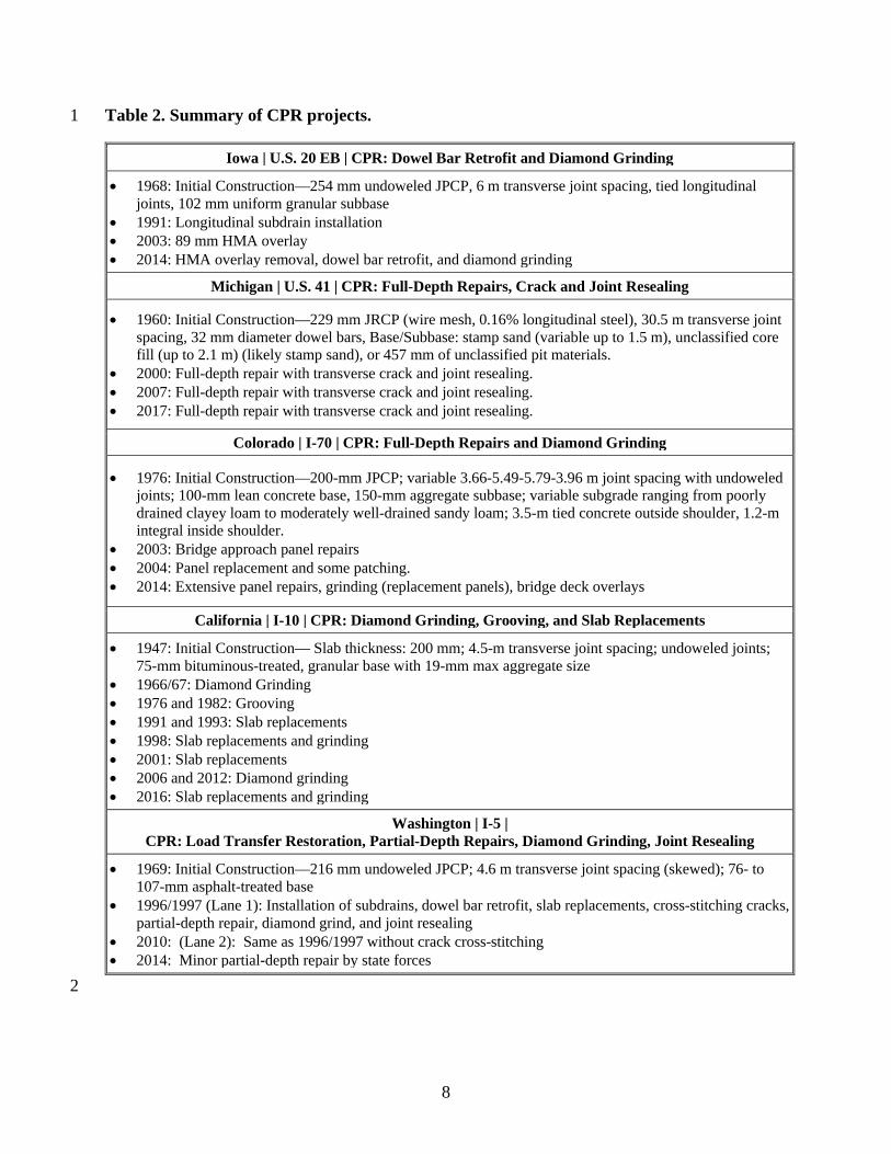
Table 2. Summary of CPR projects. 1
2
Iowa | U.S. 20 EB | CPR: Dowel Bar Retrofit and Diamond Grinding
• 1968: Initial Construction––254 mm undoweled JPCP, 6 m transverse joint spacing, tied longitudinal joints, 102 mm uniform granular subbase
• 1991: Longitudinal subdrain installation • 2003: 89 mm HMA overlay • 2014: HMA overlay removal, dowel bar retrofit, and diamond grinding
Michigan | U.S. 41 | CPR: Full-Depth Repairs, Crack and Joint Resealing
• 1960: Initial Construction––229 mm JRCP (wire mesh, 0.16% longitudinal steel), 30.5 m transverse joint spacing, 32 mm diameter dowel bars, Base/Subbase: stamp sand (variable up to 1.5 m), unclassified core fill (up to 2.1 m) (likely stamp sand), or 457 mm of unclassified pit materials.
• 2000: Full-depth repair with transverse crack and joint resealing. • 2007: Full-depth repair with transverse crack and joint resealing. • 2017: Full-depth repair with transverse crack and joint resealing.
Colorado | I-70 | CPR: Full-Depth Repairs and Diamond Grinding
• 1976: Initial Construction––200-mm JPCP; variable 3.66-5.49-5.79-3.96 m joint spacing with undoweled joints; 100-mm lean concrete base, 150-mm aggregate subbase; variable subgrade ranging from poorly drained clayey loam to moderately well-drained sandy loam; 3.5-m tied concrete outside shoulder, 1.2-m integral inside shoulder.
• 2003: Bridge approach panel repairs • 2004: Panel replacement and some patching. • 2014: Extensive panel repairs, grinding (replacement panels), bridge deck overlays
California | I-10 | CPR: Diamond Grinding, Grooving, and Slab Replacements
• 1947: Initial Construction–– Slab thickness: 200 mm; 4.5-m transverse joint spacing; undoweled joints; 75-mm bituminous-treated, granular base with 19-mm max aggregate size
• 1966/67: Diamond Grinding • 1976 and 1982: Grooving • 1991 and 1993: Slab replacements • 1998: Slab replacements and grinding • 2001: Slab replacements • 2006 and 2012: Diamond grinding • 2016: Slab replacements and grinding
Washington | I-5 | CPR: Load Transfer Restoration, Partial-Depth Repairs, Diamond Grinding, Joint Resealing
• 1969: Initial Construction––216 mm undoweled JPCP; 4.6 m transverse joint spacing (skewed); 76- to 107-mm asphalt-treated base
• 1996/1997 (Lane 1): Installation of subdrains, dowel bar retrofit, slab replacements, cross-stitching cracks, partial-depth repair, diamond grind, and joint resealing
• 2010: (Lane 2): Same as 1996/1997 without crack cross-stitching • 2014: Minor partial-depth repair by state forces
9
1
2
3
4
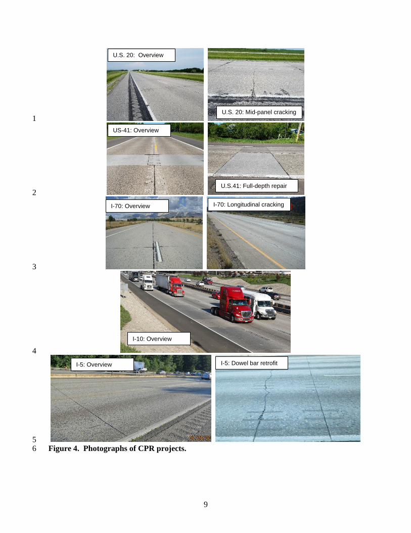
5 Figure 4. Photographs of CPR projects. 6
U.S. 20: Overview
U.S. 20: Mid-panel cracking
US-41: Overview
U.S.41: Full-depth repair
I-70: Overview
I-10: Overview
I-5: Overview
I-70: Longitudinal cracking
I-5: Dowel bar retrofit
10
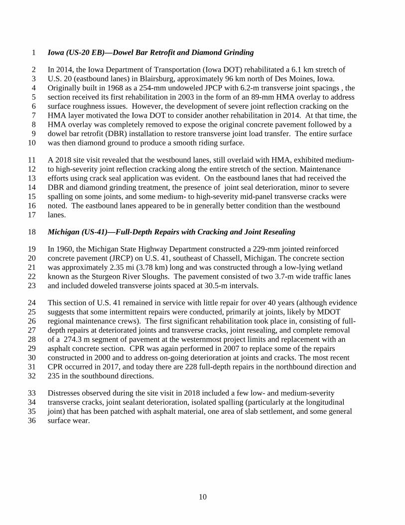
Iowa (US-20 EB)––Dowel Bar Retrofit and Diamond Grinding 1
In 2014, the Iowa Department of Transportation (Iowa DOT) rehabilitated a 6.1 km stretch of 2 U.S. 20 (eastbound lanes) in Blairsburg, approximately 96 km north of Des Moines, Iowa. 3 Originally built in 1968 as a 254-mm undoweled JPCP with 6.2-m transverse joint spacings , the 4 section received its first rehabilitation in 2003 in the form of an 89-mm HMA overlay to address 5 surface roughness issues. However, the development of severe joint reflection cracking on the 6 HMA layer motivated the Iowa DOT to consider another rehabilitation in 2014. At that time, the 7 HMA overlay was completely removed to expose the original concrete pavement followed by a 8 dowel bar retrofit (DBR) installation to restore transverse joint load transfer. The entire surface 9 was then diamond ground to produce a smooth riding surface. 10
A 2018 site visit revealed that the westbound lanes, still overlaid with HMA, exhibited medium- 11 to high-severity joint reflection cracking along the entire stretch of the section. Maintenance 12 efforts using crack seal application was evident. On the eastbound lanes that had received the 13 DBR and diamond grinding treatment, the presence of joint seal deterioration, minor to severe 14 spalling on some joints, and some medium- to high-severity mid-panel transverse cracks were 15 noted. The eastbound lanes appeared to be in generally better condition than the westbound 16 lanes. 17
Michigan (US-41)––Full-Depth Repairs with Cracking and Joint Resealing 18
In 1960, the Michigan State Highway Department constructed a 229-mm jointed reinforced 19 concrete pavement (JRCP) on U.S. 41, southeast of Chassell, Michigan. The concrete section 20 was approximately 2.35 mi (3.78 km) long and was constructed through a low-lying wetland 21 known as the Sturgeon River Sloughs. The pavement consisted of two 3.7-m wide traffic lanes 22 and included doweled transverse joints spaced at 30.5-m intervals. 23
This section of U.S. 41 remained in service with little repair for over 40 years (although evidence 24 suggests that some intermittent repairs were conducted, primarily at joints, likely by MDOT 25 regional maintenance crews). The first significant rehabilitation took place in, consisting of full-26 depth repairs at deteriorated joints and transverse cracks, joint resealing, and complete removal 27 of a 274.3 m segment of pavement at the westernmost project limits and replacement with an 28 asphalt concrete section. CPR was again performed in 2007 to replace some of the repairs 29 constructed in 2000 and to address on-going deterioration at joints and cracks. The most recent 30 CPR occurred in 2017, and today there are 228 full-depth repairs in the northbound direction and 31 235 in the southbound directions. 32
Distresses observed during the site visit in 2018 included a few low- and medium-severity 33 transverse cracks, joint sealant deterioration, isolated spalling (particularly at the longitudinal 34 joint) that has been patched with asphalt material, one area of slab settlement, and some general 35 surface wear. 36
11
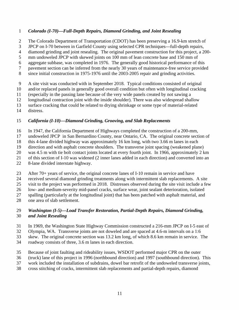
Colorado (I-70)––Full-Depth Repairs, Diamond Grinding, and Joint Resealing 1
The Colorado Department of Transportation (CDOT) has been preserving a 16.9-km stretch of 2 JPCP on I-70 between in Garfield County using selected CPR techniques––full-depth repairs, 3 diamond grinding and joint resealing. The original pavement construction for this project, a 200-4 mm undoweled JPCP with skewed joints on 100 mm of lean concrete base and 150 mm of 5 aggregate subbase, was completed in 1976. The generally good historical performance of this 6 pavement section can be inferred from the nearly 30 years of maintenance-free service provided 7 since initial construction in 1975-1976 until the 2003-2005 repair and grinding activities. 8
A site visit was conducted with in September 2018. Typical conditions consisted of original 9 and/or replaced panels in generally good overall condition but often with longitudinal cracking 10 (especially in the passing lane because of the very wide panels created by not sawing a 11 longitudinal contraction joint with the inside shoulder). There was also widespread shallow 12 surface cracking that could be related to drying shrinkage or some type of material-related 13 distress. 14
California (I-10)––Diamond Grinding, Grooving, and Slab Replacements 15
In 1947, the California Department of Highways completed the construction of a 200-mm, 16 undoweled JPCP in San Bernardino County, near Ontario, CA. The original concrete section of 17 this 4-lane divided highway was approximately 16 km long, with two 3.66 m lanes in each 18 direction and with asphalt concrete shoulders. The transverse joint spacing (weakened plane) 19 was 4.5 m with tie bolt contact joints located at every fourth joint. In 1966, approximately 2 km 20 of this section of I-10 was widened (2 inner lanes added in each direction) and converted into an 21 8-lane divided interstate highway. 22
After 70+ years of service, the original concrete lanes of I-10 remain in service and have 23 received several diamond grinding treatments along with intermittent slab replacements. A site 24 visit to the project was performed in 2018. Distresses observed during the site visit include a few 25 low- and medium-severity mid-panel cracks, surface wear, joint sealant deterioration, isolated 26 spalling (particularly at the longitudinal joint) that has been patched with asphalt material, and 27 one area of slab settlement. 28
Washington (I-5)––Load Transfer Restoration, Partial-Depth Repairs, Diamond Grinding, 29 and Joint Resealing 30
In 1969, the Washington State Highway Commission constructed a 216-mm JPCP on I-5 east of 31 Olympia, WA. Transverse joints are not doweled and are spaced at 4.6-m intervals on a 1:6 32 skew. The original concrete section was 13.2 km long, of which 8.6 km remain in service. The 33 roadway consists of three, 3.6 m lanes in each direction. 34
Because of joint faulting and rideability issues, WSDOT performed major CPR on the outer 35 (truck) lane of this project in 1996 (northbound direction) and 1997 (southbound direction). This 36 work included the installation of subdrains, dowel bar retrofit of the undoweled transverse joints, 37 cross stitching of cracks, intermittent slab replacements and partial-depth repairs, diamond 38
12
grinding, and joint resealing. A similar CPR project consisting of DBR and diamond grinding 1 was done in 2010 in the center lane (both directions). 2
This concrete section has been in service for nearly 50 years exhibiting satisfactory performance. 3 Distresses observed during the 2018 site visit included low- and medium-severity mid-panel 4 cracks, surface wear, isolated joint and crack spalling, and severe wheel path wear (from studded 5 tires) in some panels replaced during the previous CPR projects. 6
Lessons Learned from CPR Projects 7
The lessons learned from the five CPR projects are summarized below. 8
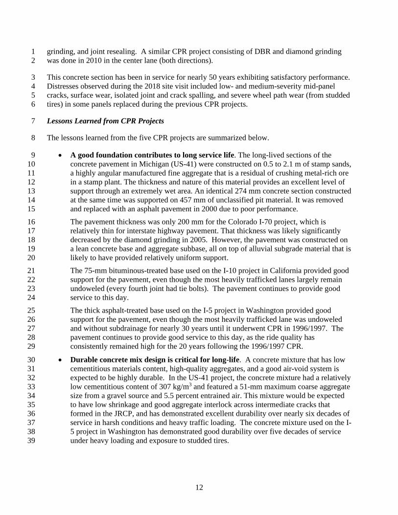
• A good foundation contributes to long service life. The long-lived sections of the 9 concrete pavement in Michigan (US-41) were constructed on 0.5 to 2.1 m of stamp sands, 10 a highly angular manufactured fine aggregate that is a residual of crushing metal-rich ore 11 in a stamp plant. The thickness and nature of this material provides an excellent level of 12 support through an extremely wet area. An identical 274 mm concrete section constructed 13 at the same time was supported on 457 mm of unclassified pit material. It was removed 14 and replaced with an asphalt pavement in 2000 due to poor performance. 15 The pavement thickness was only 200 mm for the Colorado I-70 project, which is 16 relatively thin for interstate highway pavement. That thickness was likely significantly 17 decreased by the diamond grinding in 2005. However, the pavement was constructed on 18 a lean concrete base and aggregate subbase, all on top of alluvial subgrade material that is 19 likely to have provided relatively uniform support. 20 The 75-mm bituminous-treated base used on the I-10 project in California provided good 21 support for the pavement, even though the most heavily trafficked lanes largely remain 22 undoweled (every fourth joint had tie bolts). The pavement continues to provide good 23 service to this day. 24 The thick asphalt-treated base used on the I-5 project in Washington provided good 25 support for the pavement, even though the most heavily trafficked lane was undoweled 26 and without subdrainage for nearly 30 years until it underwent CPR in 1996/1997. The 27 pavement continues to provide good service to this day, as the ride quality has 28 consistently remained high for the 20 years following the 1996/1997 CPR. 29
• Durable concrete mix design is critical for long-life. A concrete mixture that has low 30 cementitious materials content, high-quality aggregates, and a good air-void system is 31 expected to be highly durable. In the US-41 project, the concrete mixture had a relatively 32 low cementitious content of 307 kg/m3 and featured a 51-mm maximum coarse aggregate 33 size from a gravel source and 5.5 percent entrained air. This mixture would be expected 34 to have low shrinkage and good aggregate interlock across intermediate cracks that 35 formed in the JRCP, and has demonstrated excellent durability over nearly six decades of 36 service in harsh conditions and heavy traffic loading. The concrete mixture used on the I-37 5 project in Washington has demonstrated good durability over five decades of service 38 under heavy loading and exposure to studded tires. 39
13
• Proper and timely CPR activities can extend the service life of concrete pavement 1 significantly at fraction of the original construction cost. By restoring the load 2 transfer capacity of the concrete pavement and correcting the surface roughness, adequate 3 levels of serviceability can be achieved and maintained after 50 or more years of service. 4 A simple economic analysis showed that by spending approximately 20 to 35 percent of 5 the original construction costs for future maintenance and rehabilitation activities, the 6 service life of the original concrete pavement can be extended by 30 years or more. 7
• Retrofitting dowel bars and diamond grinding are key for long service life. By 8 restoring the load transfer capacity of the concrete pavement and correcting the surface 9 roughness, adequate levels of serviceability can be achieved and maintained after 50 10 years of service as seen from the U.S. 20 project in Iowa and the I-70 project in Colorado. 11
Diamond grinding is a very effective way to maintain pavement smoothness. For the 12 Colorado I-70 project, blanket diamond grinding in 2005 has certainly contributed to 13 pavement serviceability, and repair grinding in 2014 has helped to maintain good IRI 14 levels. After 70+ years of service and through four major diamond grinding projects on 15 the I-10 section in California, the pavement has been maintained with good ride quality 16 proving the efficacy of this method. 17
• HMA overlay on undoweled JPCP is not a long-term solution. An asphalt overlay of 18 a jointed concrete pavement can improve the serviceability and pavement surface 19 characteristics (friction and IRI). However, in the long run, reflective cracking becomes 20 a major distress affecting the rideability of the pavement as evident from the westbound 21 lanes of the U.S. 20 section in Iowa. 22
Concrete Overlays 23
Many state highway agencies use concrete overlays as a rehabilitation treatment for pavements 24 that are structurally deficient or degraded. Concrete overlays can be either bonded or unbonded. 25 These overlay types provide a number of benefits, including: (a) overall cost effectiveness, (b) 26 rapid and convenient construction, (c) minimal maintenance requirements, and (d) improved 27 surface characteristics (Harrington and Fick 2014). 28
Unbonded Concrete Overlays 29
Unbonded concrete overlays (UBCOL)of concrete are almost exclusively used to rehabilitate 30 concrete pavements that are in relatively poor condition (Harrington and Fick 2014). In these 31 cases, the existing concrete is treated like a stiff base course and the new concrete is separated 32 from it through either a separation layer (e.g., asphalt interlayer) or a thick geosynthetic fabric. 33 The purpose of the separation is to permit the new concrete surface to act independently from the 34 underlying pavement. Unbonded concrete overlays can range in thickness from about 152 mm to 35 254 mm or more depending on the traffic loadings and design conditions. 36
14
Bonded Concrete Overlays 1
Bonded concrete overlays (BCOL) of concrete should be applied only to existing concrete 2 pavements in good condition. These overlays are intended to structurally enhance the existing 3 pavement or to correct a functional deficiency that cannot be addressed by another means 4 (Harrington and Fick 2014). A bonded concrete overlay relies largely on the original pavement 5 and sublayers for structural support with the overlay primarily serving as an improved riding 6 surface. As such, a critical element in the performance of the overlay is the achievement of an 7 effective bond to the existing pavement. 8
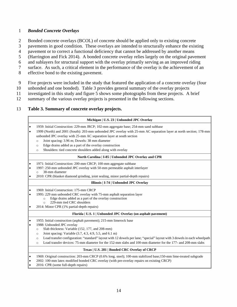
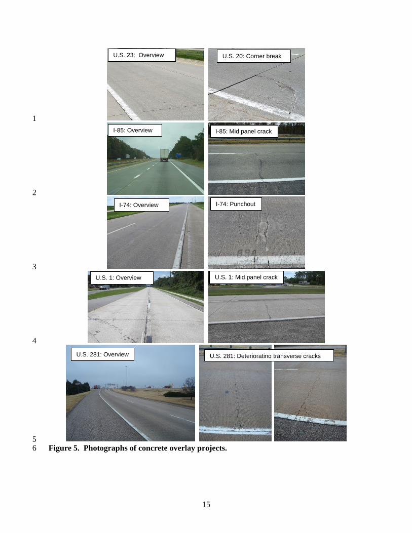
Five projects were included in the study that featured the application of a concrete overlay (four 9 unbonded and one bonded). Table 3 provides general summary of the overlay projects 10 investigated in this study and figure 5 shows some photographs from these projects. A brief 11 summary of the various overlay projects is presented in the following sections. 12
Table 3. Summary of concrete overlay projects. 13
Michigan | U.S. 23 | Unbonded JPC Overlay
• 1959: Initial Construction: 229-mm JRCP; 102-mm aggregate base; 254-mm sand subbase • 1999 (North) and 2001 (South): 203-mm unbonded JPC overlay with 25-mm AC separation layer at north section; 178-mm
unbonded JPC overlay with 25-mm AC separation layer at south section o Joint spacing: 3.96 m; Dowels: 38 mm diameter o Edge drains added as a part of the overlay construction o Shoulders: tied concrete shoulders added along with overlay
North Carolina | I-85 | Unbonded JPC Overlay and CPR
• 1971: Initial Construction: 200-mm CRCP; 100-mm aggregate subbase • 1997: 250-mm unbonded JPC overlay with 50-mm permeable asphalt interlayer
o 38-mm diameter • 2010: CPR (blanket diamond grinding, joint sealing, minor partial-depth repairs)
Illinois | I-74 | Unbonded JPC Overlay
• 1969: Initial Construction: 175-mm CRCP • 1995: 229 mm unbonded CRC overlay with 75-mm asphalt separation layer
o Edge drains added as a part of the overlay construction o 229-mm tied CRC shoulders
• 2014: Minor CPR (1% partial-depth repairs)
Florida | U.S. 1 | Unbonded JPC Overlay (on asphalt pavement)
• 1955: Initial construction (asphalt pavement); 215-mm limerock base • 1988: Unbonded JPC overlay
o Slab thickness: Variable (152, 177, and 208-mm) o Joint spacing: Variable (3.7, 4.3, 4.9, 5.5, and 6.1 m) o Load transfer configuration: “standard” layout with 12 dowels per lane; “special” layout with 3 dowels in each wheelpath o Load transfer devices: 75-mm diameter for the 152-mm slabs and 100-mm diameter for the 177- and 208-mm slabs
Texas | U.S. 281 | Bonded CRC Overlay of CRCP
• 1969: Original construction: 203-mm CRCP (0.6% long. steel); 100-mm stabilized base;150-mm lime-treated subgrade • 2002: 100-mm latex modified bonded CRC overlay (with pre-overlay repairs on existing CRCP) • 2016: CPR (some full-depth repairs)
15
1
2
3
4
5 Figure 5. Photographs of concrete overlay projects. 6
U.S. 23: Overview U.S. 20: Corner break
I-85: Overview I-85: Mid panel crack
I-74: Overview
U.S. 1: Overview
U.S. 281: Overview
I-74: Punchout
U.S. 281: Deteriorating transverse cracks
U.S. 1: Mid panel crack
16
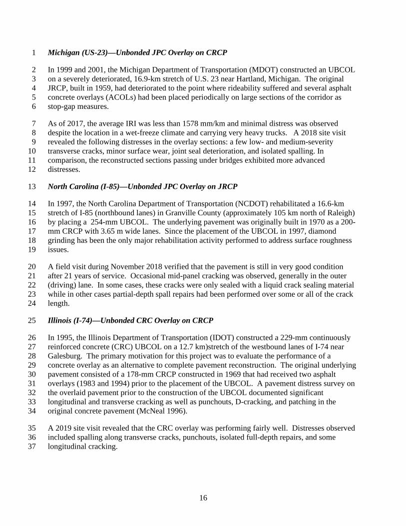
Michigan (US-23)––Unbonded JPC Overlay on CRCP 1
In 1999 and 2001, the Michigan Department of Transportation (MDOT) constructed an UBCOL 2 on a severely deteriorated, 16.9-km stretch of U.S. 23 near Hartland, Michigan. The original 3 JRCP, built in 1959, had deteriorated to the point where rideability suffered and several asphalt 4 concrete overlays (ACOLs) had been placed periodically on large sections of the corridor as 5 stop-gap measures. 6
As of 2017, the average IRI was less than 1578 mm/km and minimal distress was observed 7 despite the location in a wet-freeze climate and carrying very heavy trucks. A 2018 site visit 8 revealed the following distresses in the overlay sections: a few low- and medium-severity 9 transverse cracks, minor surface wear, joint seal deterioration, and isolated spalling. In 10 comparison, the reconstructed sections passing under bridges exhibited more advanced 11 distresses. 12
North Carolina (I-85)––Unbonded JPC Overlay on JRCP 13
In 1997, the North Carolina Department of Transportation (NCDOT) rehabilitated a 16.6-km 14 stretch of I-85 (northbound lanes) in Granville County (approximately 105 km north of Raleigh) 15 by placing a 254-mm UBCOL. The underlying pavement was originally built in 1970 as a 200-16 mm CRCP with 3.65 m wide lanes. Since the placement of the UBCOL in 1997, diamond 17 grinding has been the only major rehabilitation activity performed to address surface roughness 18 issues. 19
A field visit during November 2018 verified that the pavement is still in very good condition 20 after 21 years of service. Occasional mid-panel cracking was observed, generally in the outer 21 (driving) lane. In some cases, these cracks were only sealed with a liquid crack sealing material 22 while in other cases partial-depth spall repairs had been performed over some or all of the crack 23 length. 24
Illinois (I-74)––Unbonded CRC Overlay on CRCP 25
In 1995, the Illinois Department of Transportation (IDOT) constructed a 229-mm continuously 26 reinforced concrete (CRC) UBCOL on a 12.7 km)stretch of the westbound lanes of I-74 near 27 Galesburg. The primary motivation for this project was to evaluate the performance of a 28 concrete overlay as an alternative to complete pavement reconstruction. The original underlying 29 pavement consisted of a 178-mm CRCP constructed in 1969 that had received two asphalt 30 overlays (1983 and 1994) prior to the placement of the UBCOL. A pavement distress survey on 31 the overlaid pavement prior to the construction of the UBCOL documented significant 32 longitudinal and transverse cracking as well as punchouts, D-cracking, and patching in the 33 original concrete pavement (McNeal 1996). 34
A 2019 site visit revealed that the CRC overlay was performing fairly well. Distresses observed 35 included spalling along transverse cracks, punchouts, isolated full-depth repairs, and some 36 longitudinal cracking. 37
17
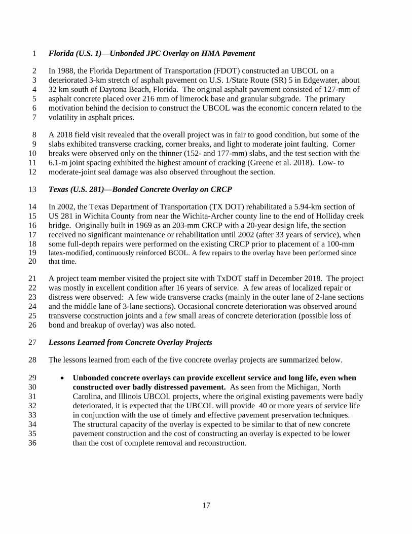
Florida (U.S. 1)––Unbonded JPC Overlay on HMA Pavement 1
In 1988, the Florida Department of Transportation (FDOT) constructed an UBCOL on a 2 deteriorated 3-km stretch of asphalt pavement on U.S. 1/State Route (SR) 5 in Edgewater, about 3 32 km south of Daytona Beach, Florida. The original asphalt pavement consisted of 127-mm of 4 asphalt concrete placed over 216 mm of limerock base and granular subgrade. The primary 5 motivation behind the decision to construct the UBCOL was the economic concern related to the 6 volatility in asphalt prices. 7
A 2018 field visit revealed that the overall project was in fair to good condition, but some of the 8 slabs exhibited transverse cracking, corner breaks, and light to moderate joint faulting. Corner 9 breaks were observed only on the thinner (152- and 177-mm) slabs, and the test section with the 10 6.1-m joint spacing exhibited the highest amount of cracking (Greene et al. 2018). Low- to 11 moderate-joint seal damage was also observed throughout the section. 12
Texas (U.S. 281)––Bonded Concrete Overlay on CRCP 13
In 2002, the Texas Department of Transportation (TX DOT) rehabilitated a 5.94-km section of 14 US 281 in Wichita County from near the Wichita-Archer county line to the end of Holliday creek 15 bridge. Originally built in 1969 as an 203-mm CRCP with a 20-year design life, the section 16 received no significant maintenance or rehabilitation until 2002 (after 33 years of service), when 17 some full-depth repairs were performed on the existing CRCP prior to placement of a 100-mm 18 latex-modified, continuously reinforced BCOL. A few repairs to the overlay have been performed since 19 that time. 20
A project team member visited the project site with TxDOT staff in December 2018. The project 21 was mostly in excellent condition after 16 years of service. A few areas of localized repair or 22 distress were observed: A few wide transverse cracks (mainly in the outer lane of 2-lane sections 23 and the middle lane of 3-lane sections). Occasional concrete deterioration was observed around 24 transverse construction joints and a few small areas of concrete deterioration (possible loss of 25 bond and breakup of overlay) was also noted. 26
Lessons Learned from Concrete Overlay Projects 27
The lessons learned from each of the five concrete overlay projects are summarized below. 28
• Unbonded concrete overlays can provide excellent service and long life, even when 29 constructed over badly distressed pavement. As seen from the Michigan, North 30 Carolina, and Illinois UBCOL projects, where the original existing pavements were badly 31 deteriorated, it is expected that the UBCOL will provide 40 or more years of service life 32 in conjunction with the use of timely and effective pavement preservation techniques. 33 The structural capacity of the overlay is expected to be similar to that of new concrete 34 pavement construction and the cost of constructing an overlay is expected to be lower 35 than the cost of complete removal and reconstruction. 36
18
• A good drainage system is essential to a well-performing UBCOL. On the Michigan 1 U.S. 23 overlay project, some isolated areas of slab cracking and pumping were linked to 2 poor drainage. 3
• Use of a separator layer improves UBCOL performance. The use of an asphalt 4 concrete separator layer (≥25 mm thickness) prior to the construction of the UBCOL 5 appears to be an effective method to minimize reflective cracking. 6
• If properly designed and constructed, unbonded concrete overlays of existing 7 asphalt pavements can provide long service lives. After 28 years of service, only a 8 small fraction of the slabs (5 percent; 33 out of the total 612 slabs) in the experimental 9 section on U.S. 1 exhibited some form of cracking in the in 2015; most of these occurred 10 on the segments with the longer joint spacings (6.1 m). 11
• Bonded concrete overlay (with pre-overlay repairs) can successfully and greatly 12 extended the life of the original pavement, providing excellent ride quality with 13 minimal maintenance. Bonded concrete overlays of concrete pavement offer the 14 potential for a significant increase in pavement structural capacity for relatively little 15 cost. The U.S. 281 project in Texas demonstrated that additional pavement concrete 16 pavement life can be obtained using bonded concrete overlays at relatively low unit costs. 17 An innovative 24-hour rolling, lane-at-a-time closure approach used in the construction 18 of this project also demonstrated that concrete overlays can be constructed quickly and 19 with relatively little impact to the traveling public. 20
• Loss of bond can result in rapid deterioration of a bonded concrete overlay. As 21 observed in a few small localized areas of the U.S. 281 project in Texas, if bond between 22 the overlay and original pavement is lost, the overlay can deteriorate quickly. 23
24
4. CONCLUDING REMARKS 25 26 Three broad preservation strategies, working in concert, can be used to help ensure the longevity 27 of concrete pavements. The first is to design and construct concrete pavements for long-life, 28 which requires the selection of volumetrically stable and durable materials, the selection of 29 design features that reduce load- and environmentally induced stresses, and the construction of a 30 high-quality pavement. The design and construction of long-life concrete pavements do not 31 require any special or exceptional measures, but instead rely upon applying common techniques 32 with diligence and attentiveness. For long-life concrete pavements, the slab thickness is 33 typically increased slightly to enhance structural load-carrying capacity and to accommodate 34 future grinding. Greater attention is paid to the supporting layers, ensuring that they are provide 35 uniform support, are non-erodible, and facilitate good drainage. Other design features are 36 implemented to reduce stress, including the use of relatively short joint spacing, the inclusion of 37 dowels at transverse joints, and the addition of widened slabs or tied shoulders to provide edge 38 support. Concrete mixtures are proportioned to be durable, should exhibit good volume stability 39 under temperature and moisture variations, and possess reduced permeability. 40
19
The second strategy involves the application of CPR techniques as a means to maintain a high 1 level of serviceability. CPR can be the most economical solution for long-term concrete 2 pavement preservation if the existing pavement is in sound structural condition and free of 3 materials-related distresses (MRD), such as D-cracking or ASR. If this is the case, non-invasive 4 CPR preservation strategies can often be employed with minimal disruption to traffic to maintain 5 pavement functionality for many years beyond the original design life. 6
The third strategy involves the use of concrete overlays as a way to extend pavement life. With 7 regards to unbonded concrete overlays of concrete, most have been used to restore structural 8 capacity to highly distressed concrete pavements, but there is no reason that they could not be 9 used as a preservation strategy on a concrete pavement that is currently in good condition. The 10 use of thin bonded concrete overlays of concrete have also demonstrated good success in 11 correcting surface or structural deficiencies but achieving a strong and effective bond is essential 12 to the long-term performance of these structures. 13
14
5. ACKNOWLEDGMENTS 15 16 The authors would like to thank the various State Departments of Transportation (Minnesota, 17 Iowa, Michigan, Colorado, California, Washington, North Carolina, Illinois, Florida, and Texas) 18 for helping with the site visit and providing all the project data included in this paper. This 19 project was sponsored by the Federal Highway Administration. 20
21
6. DISCLAIMER 22 23 The U.S. Department of Transportation assumes no liability for the use of the information 24 contained in this document. This paper does not constitute a standard, specification, or 25 regulation. 26
27
7. REFERENCES 28 29 American Concrete Pavement Association (ACPA). 1997. The Concrete Pavement Restoration 30 Guide. TB020P. American Concrete Pavement Association, Skokie, IL. 31
Darter, M. I., and E. J. Barenberg. 1977. Design of a Zero-Maintenance Plain Jointed Concrete 32 Pavement, Volume I-Development of Design Procedures. FHWA-RD-77-111. Federal Highway 33 Administration, McLean, VA. 34
Federal Highway Administration (FHWA). 2006. High Performance Concrete Pavements: 35 Project Summary. Federal Highway Administration, Washington, DC. 36
20
Geiger, D. R. 2005. Pavement Preservation Definitions. Technical Memorandum. Federal 1 Highway Administration, Washington, DC. 2
Greene, J., O. Kwon, A. Nazef, and B. Choubane. 2018. “A Long-Term Performance 3 Evaluation of an Experimental Concrete Overlay.” Transportation Research Record, 4 Transportation Research Board, Washington, DC. 5
Harrington, D., and G. Fick. 2014. Guide to Concrete Overlays: Sustainable Solutions for 6 Resurfacing and Rehabilitating Existing Pavements. 3rd Edition. TB021.03P. American Concrete 7 Pavement Association, Washington, DC. 8
McNeal, A. F. 1996. Planning, Design and Construction of an Unbonded Concrete Overlay. 9 Physical Research Report No. 122. Illinois Department of Transportation, Springfield, IL. 10
Smith, K. 2005. Concrete Pavement Rehabilitation and Preservation Treatments. FHWA-IF-06-11 005. Federal Highway Administration, Washington, DC. 12 Smith, K. D., D. Harrington, L. Pierce, P. Ram, and K. L. Smith. 2014. Concrete Pavement 13 Preservation Guide – Second Edition. FHWA-HIF-14-014. Federal Highway Administration, 14 Washington, DC. 15
Tayabji, S. and S. Lim. 2007. Long-Life Concrete Pavements: Best Practices and Directions from the 16 States. FHWA-HIF-07-030. Federal Highway Administration. Washington, DC. 17
Van Dam, T., K. Smith, M. Snyder, P. Ram, and N. Dufalla. 2019. Strategies for Concrete 18 Pavement Preservation: Interim Report. FHWA-HIF-18-025. Federal Highway Administration, 19 Washington, DC. 20
21