Concrete Forming Accessories Handbook
107
FORMING ACCESSORIES HANDBOOK CONCRETE CONSTRUCTION PRODUCTS BUILDING STRENGTH ™
-
Upload
hoangthuan -
Category
Documents
-
view
237 -
download
0
Transcript of Concrete Forming Accessories Handbook

FORMING ACCESSORIES HANDBOOK
CONCRETE
CONSTRUCTION PRODUCTS
BUILDING STRENGTH™

12/15
Mis
cella
neou
sFl
at S
lab
Form
ing
Pro
duct
sM
ediu
m/H
eavy
For
min
g P
rodu
cts
Ligh
t For
min
g P
rodu
cts
Gen
eral
and
Tec
hnic
al In
form
atio
nTable of Contents
General and Technical Information.............. 1Definitions ....................................................................... 1Safety Notes and Product Application ........................ 1Dayton Superior Technical Services ......................... 1Usage Affecting a Product’s Safe Working Load .............2Induced Tension Loads ................................................. 6Induced Shear Loads .................................................... 6Combined Shear and Tension Loads .......................... 6Forming Accessories Selection...................................7Load Carrying Capacity Classifications: .....................7Method of Use Classifications: ....................................7Lumber and Form Tie Analysis ....................................7Calculations for Formwork Costs ............................... 8Determining Required Quantities of Form Ties ......... 8Typical Formwork Designs for Wall Forms............... 9Vertical Formwork Design Loads ..............................10Slab Formwork Design Loads .....................................11Technical Data–Plywood .............................................12Technical Data–Lumber ............................................... 13
Light Forming ............................................. 19A2 Plastic Cones .......................................................... 19A3 Standard Snap Tie ................................................. 19A3 Heavy Snap Tie......................................................20A4H Hex Head Snap Tie ............................................20How to Break Back A4 Snap Ties .............................21A5 Threaded PullOut Tie .............................................21A6 Spandrel Point Tie .................................................21A7 Spandrel Hook Tie.................................................22A7A Spandrel Plate Tie ..............................................22A9 / A9H Tip-To-Tip Tie, Standard and Heavy .........22A10 Plate Tie ................................................................ 23A13 Metal Strapping .................................................... 23A16 Omni Wedge.......................................................... 23A16SB Snap Bracket................................................... 23A18 Panel Bolt .............................................................. 23A19 Corner Washer ..................................................... 24A21 Strap Ties And Accessories .............................. 24A21X Flat Tie ................................................................ 25A22 Spreader Cleats ................................................. 26A27 and A27-M Turnbuckle Form Aligners ........... 27A28 Adjustable Kicker ................................................ 27A29 Snap Tie Wrench ................................................. 28A31 Wrench Head Snap Tie Socket .......................... 28A40 Cone Removal Wrench ....................................... 28A43 Footing Tie ........................................................... 28A44 Stainless Steel Snap Tie ................................... 29A45 Base Tie ............................................................... 29A46 Loop Panel Tie, Standard and Heavy ............... 29A48 Gang Loop Tie, Standard and Heavy ............... 30A51 Wedge Bolt ............................................................ 30A52 Z Tie Holder and A53 Waler Tie ....................... 30A54 Snaplug® ...............................................................31A55 Sure-Lock Tie, A56 Sure-Lock Bracket, .........31A57 Sure-Lock Strongback Bracket, .......................31A63 Strongback Loop Tie .......................................... 32A81 Jahn® “A” Bracket ............................................... 32A82 Jahn® “C” Bracket .............................................. 33A83 Jahn® Cornerlock ............................................... 33A89 Jahn® Scaffold Jack ........................................... 34How to Use the Jahn® Forming System ................. 35Using Single Vertical Wales for Curved Walls ........42Column and Pilaster Forming Suggestions ............42A90 Scaffold Bracket Jack ........................................ 43A93C Sure Guard® Rail Post System ....................... 44A97 4x4 Post Shore Clamp ....................................... 44A100 Speed Step® Bracket ........................................ 45A110 Dayton Superior Metal Rib ............................... 45
Medium/Heavy Forming ............................47B1 Two Strut Coil Tie and B2 Four Strut Coil Tie ......... 47B1B3 and B2B3 Screw-On Coil Tie .......................... 48Coils ............................................................................... 49B6 Welding Coil Tie ..................................................... 49B7 and B22 Inserts (Crimp) ...................................... 49B11 Flat Washers ..........................................................50B12 Coil Rod .................................................................50B12A D/R Thread Bar ..................................................51B13 Coil Nut and B25 Heavy Coil Nut ...................... 52B14 Coil Bolts ............................................................... 52B14A Adjustable Coil Bolt .......................................... 53B14W Wale Bolt Assembly ......................................... 54B15 Plastic Cone Removal Wrench ........................... 54B16 Coil Loop Insert Straight .................................... 54B17 Double Flared Coil Loop Insert .......................... 55B18 Single Flared Coil Insert ..................................... 55B20 Wale Holder .......................................................... 56B21 Plylag ..................................................................... 56B27 and D6 Nut Washer ............................................. 57B29 Loose Plastic Cone ............................................. 57B30 Screw-On Plastic Cones ................................... 58B31 Rock Anchor ......................................................... 58B32 Handle Coil Nut ................................................... 59B33 Double Flared Criss Cross Coil Loop Insert .........59B37 Toggle Tie .............................................................60B39 Wing Nut ...............................................................60B40 Plastic Setback Plug ...........................................61B42 and D22 Batter Washer .......................................61B43 Triple Flared Coil Loop Insert ............................61D1 and D18 Inside Tie Rods ........................................ 62D1-J, D1LA and D1L Hook Bolts ................................ 63D1S Anchor Bolt Sleeve ............................................. 63D2 and D30 She-Bolts ............................................... 64D4 Hex Coupling Nut .................................................. 65D9 Taper Ties ............................................................... 65D9A D/R Thread Bar Taper Tie ................................. 66D12 Rod Clamps ........................................................... 66D12A Pencil Rod .......................................................... 67D12F Form Clamp ........................................................ 67D14 Tightening Wrench .............................................. 67D21 Rebar Clip and Form Spreader .......................... 68D24 Weld Angle Bracket ............................................ 68D25 Fitting Up Bolt and D26 Fitting Up Nut ........... 69D27 Lag Bolt ................................................................. 69D30A D/R Thread Bar She-Bolt ............................... 70D32 Closed Coupler .................................................... 70D33 Water Resistant Washer ..................................... 70D40 He-Bolts ................................................................ 71Typical He-Bolt Anchors ............................................ 72Special He-Bolt Inserts .............................................. 72D42 Bag Ties ............................................................... 72PC110 Impalement Safety Cap ....................................73D46 Tie Wire .................................................................73D48 Sure-Guard Rebar Protective Cap ....................73A58 Sure Plug ..............................................................74A59 Insertion Tool ........................................................74F1 Screw Anchor and F2 Screw Anchor Bolt ........ 75
General Slabwork .......................................77C1B and C1C Wedge Hangers .....................................77C2 Coil Hanger Saddle Type ...................................... 78C3 Coil Half Hanger .................................................... 79C13 Plate Saddle Hanger ............................................ 79C13A All-Wire Saddle Hanger ...................................80C14 Channel Hanger.....................................................81Methods of Screeding ................................................ 82G1 Pipe Holder ............................................................. 83G1U Special U-Shaped Cradle Head ........................ 83G2 Screed Chair Bases .............................................. 83G2J Joist Type Adjustable Screed Base ................. 83G2S Special Height Screed Base ............................. 84G3 Screed Chair Base With Sand Plate ................... 84G4 and G4A Screed Bases, Drive Type ................... 84G5 Screed Bases, Free Fit Type ............................... 85G7 Screed Chair Base for Steel Deck ...................... 85G8 Form Bracket ......................................................... 85G11 Screed Stake for Pipe ......................................... 86G14 Heavy Duty Screed Holders ............................... 86G15 Heavy Duty Screed Support .............................. 86G16 Heavy Duty Screed Chair Base ......................... 87G27 Round Stake ......................................................... 87G28 and G29 Screed Bracket .................................... 87G33 Screed Key Joint ................................................. 88G34 Load Key Joint ..................................................... 88G35 Plastic Cap Strip ................................................. 88G37 Stake ..................................................................... 88How to Use Screed Key Joint ................................... 89Proper Method for Installing Load Key Joint ...........91G60 Curb Smart .......................................................... 93Curb Smart Installation .............................................. 94Supports for Rebar and Wire Mesh .......................... 95
Miscellaneous .............................................99Formliner Materials .................................................... 99F56, F57, F58, F59, F60, F61 Expanded Coil
Inserts ........................................................... 100F42 Loop Ferrule Insert ........................................... 100F44 Thin Slab Ferrule Insert ................................... 100F7, F7L Shelf Angle Insert ....................................... 100F54 Ductile Embed.................................................... 100F54C Nylon Rail Track Insert .................................. 100
Index..........................................................102
12/15
Miscellaneous
Flat Slab Form
ing Products
Medium
/Heavy Form
ing Products
Light Forming P
roductsG
eneral and Technical Information
About Dayton Superior
Dayton Superior’s reputation as the industry leader in the design, manufacturing and distribution of specialized concrete construction products is the result of innovation backed by more than 100 years of experience. Proven concrete solutions that span a wide breadth of industry disciplines and the most comprehensive product offering in concrete construc-tion makes Dayton Superior the preferred partner for distributors, contractors, architects and engineers.
Dayton Superior’s products are found on virtually every major construction site in North America including:
• Local roadways, national highways, runways and bridges
• High-profile urban high-rises and suburban mixed-use structures
• Water treatment and government service facilities, education and healthcare institutions
• Entertainment venues, retail and restaurant projects
With an unwavering commitment to continuous improve-ment, Dayton Superior employs creativity and discipline to develop timely and innovative solutions that add value for customers and distributors through:
• The largest, most experienced engineering and sales team in the industry
• Access to a wealth of detailed technical information via the Dayton Superior website coupled with a highly skilled team of technical service professionals
• A team of 70+ customer service advisors providing responsive customer care along with Dayton Access®, a 24/7 web-based tool providing order status information
• A nationwide distribution network of over 2,700 dealer distributor locations and 14 strategically located, company-owned distribution centers
• An unmatched track record of product innovation and industry leadership
In the concrete construction industry, Dayton Superior’s reputation for quality, service and support is unequalled.
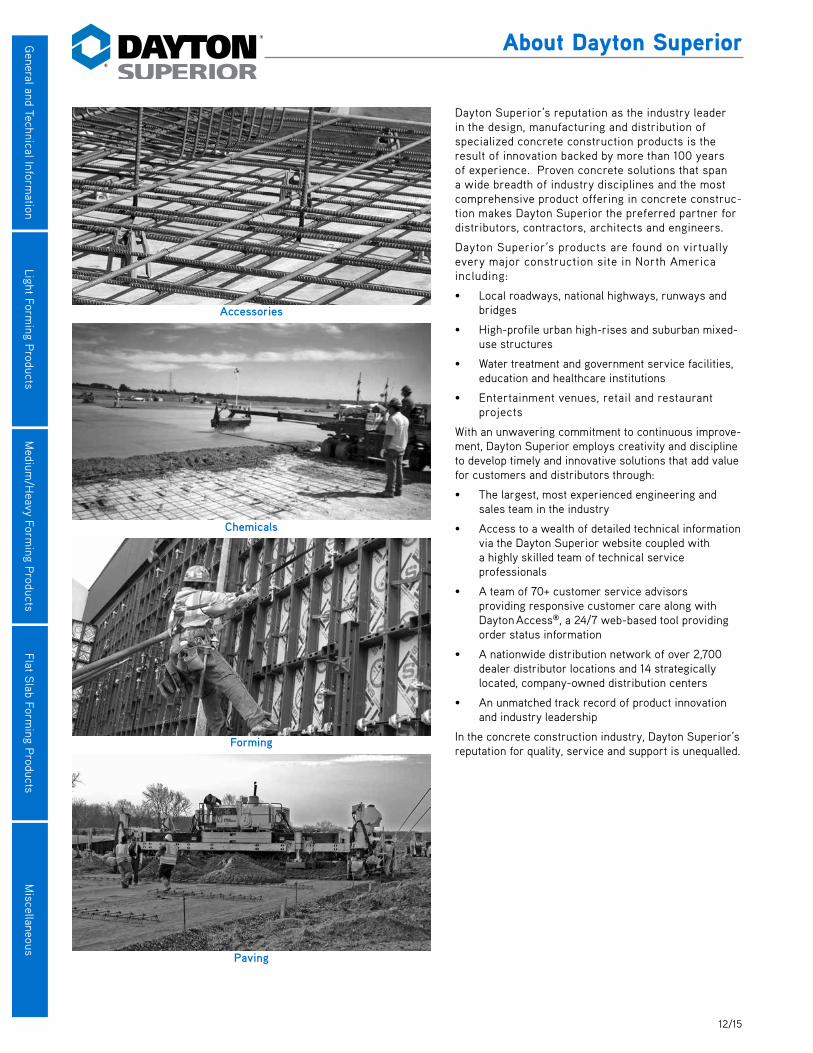
Accessories
Chemicals
Forming
Paving

112/15
Gen
eral
and
Tec
hnic
al In
form
atio
nGeneral and Technical Information
Definitions Safe Working Load — The maximum working load that should be applied to any forming product.
Ultimate Load — The load at which a product fails or will no longer support or carry a load.
Safety Factor — The theoretical reserve capability defined by dividing the ultimate load of the product by its safe working load. This is expressed as a ratio, such as 2:1 or 2 to 1 (ultimate to safe working load).
Concrete Form Pressure — The lateral pressure applied per square foot of form contact.
Slab Formwork Dead Load — The weight of fresh concrete and reinforcement bars plus the weight of the formwork.
Slab Formwork Live Load — Any additional loads imposed during the construction process, such as materials, workmen, equipment, including lateral forces.
Slab Formwork Design Load — Dead load plus live load per square foot of contact.
Formwork Impact Load — Loads caused by dumping concrete or the starting/stopping of construction related equipment.
Safety Notes and Product ApplicationDayton Superior ensures that all products meet or exceed appropriate safety requirements. However, the performance of a product can be greatly affected by the manner in which it is used. It is imperative that the user properly installs and uses the products dis-played in this publication.
Production runs are constantly tested to assure a high standard of quality. Safe working loads listed in this publication were deter-mined from independent testing and results of the Company quality assurance/quality control program.
Safety factors may be dependent on the application of a particular product. Job site conditions can often affect the safety factor of a product. Concentrated loads, such as, unsymmetrical loading, uplift, impact and lateral forces are examples of job site conditions that may affect the safety factor. The user must adjust safety factors accordingly to accommodate these various conditions.
Dayton Superior publishes the minimum safe working loads and the associated safety factors of its products and strongly advises that the minimum safety factors displayed in the table below not be compromised. When there are unusual job conditions such as mentioned above, the minimum safety factors must be increased by the user. Refer to the provisions of the American National Standards Institute (ANSI A 10.9), the Occupational Safety and Health Administration (OSHA) Act, Part 1910 and the American Concrete Institute (ACI) Recommended Practice for Concrete Formwork (ACI 347-94) when considering product safety factors.
Minimum Safety Factors of Formwork AccessoriesAccessory Safety Factor Type of Construction
Form Tie 2.0 to 1 All applications.
Form Anchor 2.0 to 1 Formwork supporting form weight and concrete pressures only.
Form Anchor 3.0 to 1 Formwork supporting form weight, concrete, construction live loads and impact.
Form Hangers 2.0 to 1 All applications.
Anchoring Inserts (Used as Form Ties) 2.0 to 1 Precast concrete panels when used as formwork.
Dayton Superior Technical ServicesDayton Superior maintains three strategically located technical departments that are well staffed with trained personnel to service inquiries concerning Dayton Superior products and/or methods.
2 12/15
General and Technical Inform
ation
General and Technical Information
Usage Affecting a Product’s Safe Working LoadForming accessories may be subjected to excessive wear, field modification/bending and straightening. Any product so noted must be discarded. Do not try to straighten bent forming accessories; discard and replace them. Also discard any reusable device that has experienced excessive loading, 70% or more, of ultimate load. Such items may have become brittle.
Every user must establish a control program that replaces reusable forming products after a predetermined time period or number of uses, regardless of product appearance. All reusable forming accessories shown in this publication are subject to wear, misuse, overloading, corrosion, deformation, intentional alteration and other factors which may affect the product’s safe working load. Therefore, it is mandatory that the user inspect all reusable accessories to determine their condition. The frequency of inspection is dependent on factors such as frequency of use, period of use, environment, etc., and is best determined by the user consistent with good construction practices.
When in doubt about the proper use or installation of Dayton Superior forming accessories, contact Dayton Superior for clarifica-tion. Failure to do so may result in exposure of workers to safety hazards, resulting in possible injury and/or death.
All safe working loads shown in this publication contain an approximate minimum safety factor. The safe working loads were established with the following factors in mind:
1. All safe working loads are based on the accessory being in new or in “as new” condition. The safe working load is considered to be the maximum load that should be applied to a product.
2. The safe working load of Dayton Superior Snap Ties and related products can only be developed when used in conjunction with A16 Omni Wedges, A81 Jahn A Brackets or A82 Jahn C Brackets.
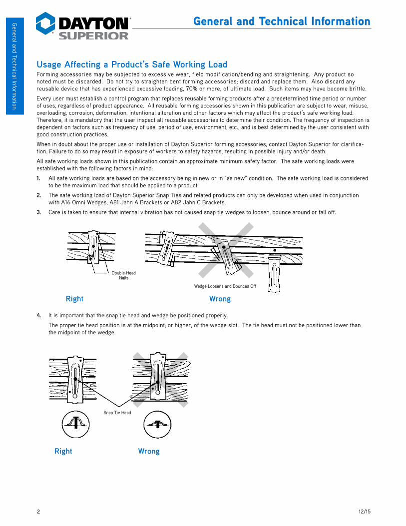
3. Care is taken to ensure that internal vibration has not caused snap tie wedges to loosen, bounce around or fall off.
4. It is important that the snap tie head and wedge be positioned properly.
The proper tie head position is at the midpoint, or higher, of the wedge slot. The tie head must not be positioned lower than the midpoint of the wedge.
Double�Head�Nails
Wedge Loosens and Bounces Off
Right Wrong
Snap Tie Head
Right Wrong
Wedge Loosens and Bounces Off
Snap Tie Head
Double Head Nails

312/15
Gen
eral
and
Tec
hnic
al In
form
atio
nGeneral and Technical Information
5. When using snap ties, correct spacing between double wales is 5/8" to 3/4".
Too much space allowed between the wales may cause crushing of the wales and/or the bending of the wedge allowing the form to bulge outward. This results in incorrect wall thickness and causes the tie spreader washers or cones to become embedded and trapped in the concrete. Trapped tie washers or cones will cause difficulties during the tie breakback operation.
6. The plastic tie cones and metal washers are designed to act as form spreaders only.
Do not attempt to draw-up warped wales with the wedge. Do not over tighten the wedge in any manner. Over tightening will cause metal spreader washers to bend out of shape or will break plastic cones resulting in incorrect wall thickness.
7. Care must be taken to be sure that all form ties are installed and used properly.
Failure to install all of the required ties or their required mating hardware will cause excessive loads to be transferred to adja-cent ties and may result in form failure.
Correct Spacing is 5/8" to 3/4" Crushing of�Wales
Spreader Washer�or Cone Embedded�in Concrete
Break Back
Right Wrong
Metal Washer�Bands
Plastic Cone�Will Shatter
Midpoint of�Wedge
Right Wrong
Tie Has�Been Left�Out
Right Wrong
Correct Spacing is 5/8" to 3/4"
Breakback
Crushing of Wales
Metal Washer Bends
Midpoint of Wedge
Tie Has Been Left Out
Plastic Washer Will Shatter
Spreader Washer or Cone Embedded in
Concrete
4 12/15
General and Technical Inform
ation
General and Technical Information
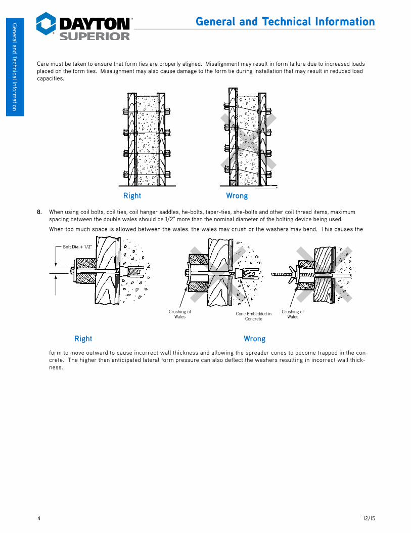
Care must be taken to ensure that form ties are properly aligned. Misalignment may result in form failure due to increased loads placed on the form ties. Misalignment may also cause damage to the form tie during installation that may result in reduced load capacities.
8. When using coil bolts, coil ties, coil hanger saddles, he-bolts, taper-ties, she-bolts and other coil thread items, maximum spacing between the double wales should be 1/2" more than the nominal diameter of the bolting device being used.
When too much space is allowed between the wales, the wales may crush or the washers may bend. This causes the
form to move outward to cause incorrect wall thickness and allowing the spreader cones to become trapped in the con-crete. The higher than anticipated lateral form pressure can also deflect the washers resulting in incorrect wall thick-ness.
Right Wrong
Crushing �of Wales
Cone Embedded�in Concrete
Bolt Dia. + 1/2"
Crushing �of Wales
Right Wrong
Crushing of Wales
Crushing of Wales
Cone Embedded in Concrete

512/15
Gen
eral
and
Tec
hnic
al In
form
atio
nGeneral and Technical Information
9. Coil bolts, coil rod and other coil thread products must have proper coil penetration. A bolting device with proper coil penetra-tion will extend past the coil a minimum of one diameter of the bolting device. For example, a properly penetrating 1/2" diam-eter coil bolt will extend past the coil a minimum of 1/2". Incorrect penetration of threaded items may result in form failure.
Failure to obtain proper penetration will cause excessive wear on the first few threads of the bolt, but more importantly it
places the entire bolt load on a smaller portion of the coil welds. The increased loading can cause the coil welds to fail and result in form failure.
10. Do not beat on the end of loop ties to force them into position. This may damage the tie and result in form failure.
11. Use only correct length form ties. Incorrect length ties, when mixed with correct ones, will cause a transfer of lateral pressure to adjacent ties and may result in form failure.
12. Do not climb on form ties.
13. Do not use impact wrenches to tighten form-tying devices.
14. Do not over-vibrate the concrete. Excessive vibration will cause concrete at the bottom of the form to remain in a liquid state longer than expected. This will result in higher than anticipated lateral form pressure and may result in a form failure. Depth of vibration should be limited to within four (4) feet of the top of the fresh concrete.
Liquid Concrete
Liquid Concrete�Full Height of�the Form
Concrete has�Stiffened Sufficiently�so Lateral Pressure�is Reduced
Right Wrong
Bolt Diameter
See Chart for�
Minimum Coil�Penetration
Insufficient�
Coil Penetration Form Failure
Right
Wrong
Bolt Diameter Minimum Coil Penetration
1/2" 2"
3/4" 2-1/4"
1" 2-1/2"
1-1/4" 2-1/2"
1-1/2" 3"
Liquid Concrete
Liquid Concrete Full Height of the
Form
See Table for
Minimum Coil Penetration
Bolt Diameter
Concrete has Stiffened
Sufficiently to Reduce Lateral
Pressure
6 12/15
General and Technical Inform
ation
General and Technical Information
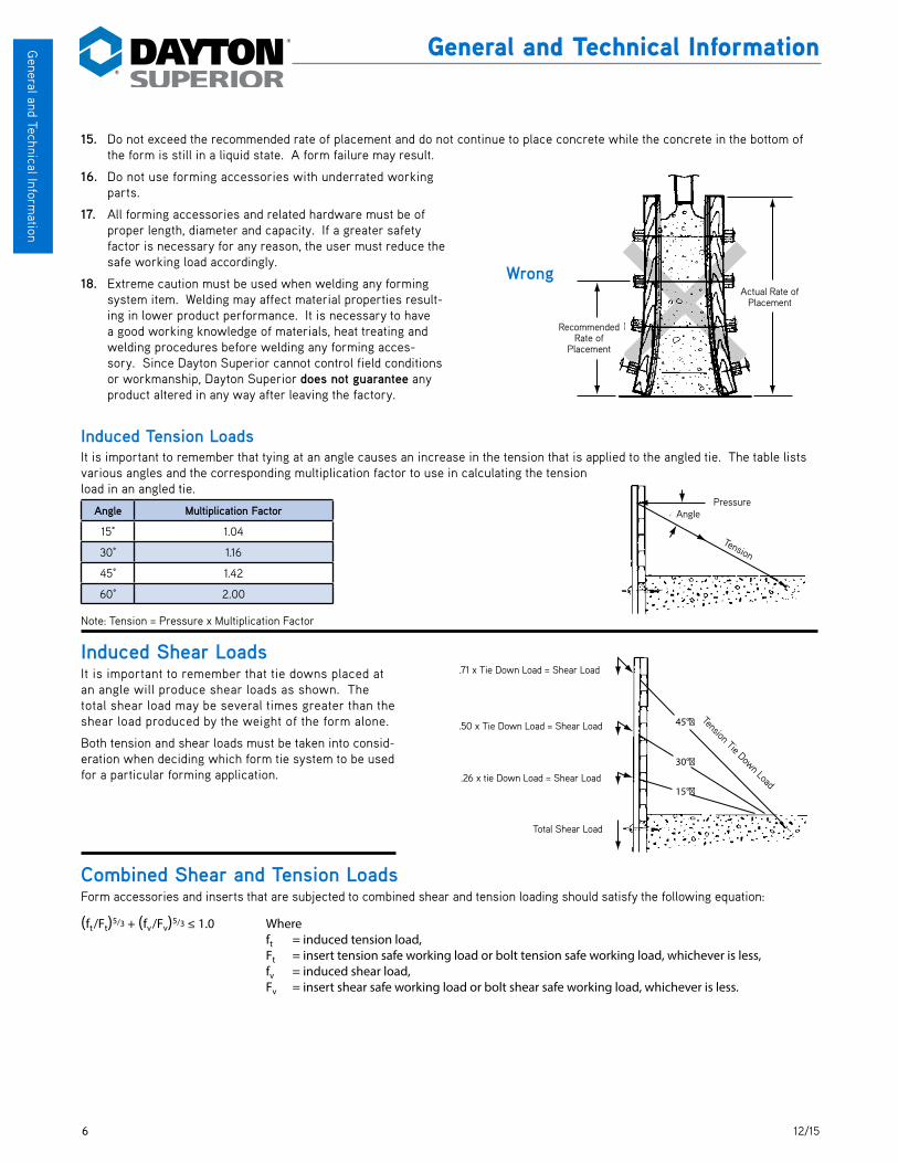
15. Do not exceed the recommended rate of placement and do not continue to place concrete while the concrete in the bottom of the form is still in a liquid state. A form failure may result.
16. Do not use forming accessories with underrated working parts.
17. All forming accessories and related hardware must be of proper length, diameter and capacity. If a greater safety factor is necessary for any reason, the user must reduce the safe working load accordingly.
18. Extreme caution must be used when welding any forming system item. Welding may affect material properties result-ing in lower product performance. It is necessary to have a good working knowledge of materials, heat treating and welding procedures before welding any forming acces-sory. Since Dayton Superior cannot control field conditions or workmanship, Dayton Superior does not guarantee any product altered in any way after leaving the factory.
Induced Tension LoadsIt is important to remember that tying at an angle causes an increase in the tension that is applied to the angled tie. The table lists various angles and the corresponding multiplication factor to use in calculating the tension load in an angled tie.
Angle Multiplication Factor
15° 1.04
30° 1.16
45° 1.42
60° 2.00
Note: Tension = Pressure x Multiplication Factor
Induced Shear LoadsIt is important to remember that tie downs placed at an angle will produce shear loads as shown. The total shear load may be several times greater than the shear load produced by the weight of the form alone.
Both tension and shear loads must be taken into consid-eration when deciding which form tie system to be used for a particular forming application.
Combined Shear and Tension LoadsForm accessories and inserts that are subjected to combined shear and tension loading should satisfy the following equation:
(ft /Ft)5/3 + (fv /Fv)5/3 ≤ 1.0 Where ft = induced tension load, Ft = insert tension safe working load or bolt tension safe working load, whichever is less, fv = induced shear load, Fv = insert shear safe working load or bolt shear safe working load, whichever is less.
Actual Rate�of Placement
Recommended�Rate of �Placement
Wrong
Pressure
Tension
AnglePressure
Tension
Angle
45°�
.71 x Tie Down Load = Shear Load
.50 x Tie Down Load = Shear Load
.26 x Tie Down Load = Shear Load
Total Shear Load
Tension Tie Down Load30°�
15°�
Tension Tie Down Load
Total Shear Load
.26 x tie Down Load = Shear Load
.50 x Tie Down Load = Shear Load
.71 x Tie Down Load = Shear Load
Recommended Rate of
Placement
Actual Rate of Placement

712/15
Gen
eral
and
Tec
hnic
al In
form
atio
nGeneral and Technical Information
Forming Accessories SelectionDayton Superior Concrete Accessories manufactures and supplies a large variety of form tying devices for concrete formwork. Form tying devices can generally be classified in two ways, by load carrying capacity and by method of use.
Load Carrying Capacity Classifications: Light Forming — Light forming form ties have safe working load values of 3,750 pounds or less. Typical light
duty ties include Snap Ties, Loop Ties and Pencil Rod.
Medium/Heavy Forming — Medium/heavy form ties have safe working load values over 3,750 pounds. Typical medium/heavy form ties include Coil Ties, She-Bolts, Taper Ties, etc.
Method of Use Classifications: Through Ties — This type of tie extends through the wall thickness and through both sides of the formwork.
Dayton Superior manufactures four types of through ties to satisfy most forming application requirements. Snap Ties, Loop Ties, Taper Ties and Pencil Rod are all quality through tie systems.
Coil Ties — The Coil Tie System consists of two Coil Bolts, two Flat Washers, optional Tie Cones and a Coil Tie. The optional Tie Cones act as an internal spreader and assures proper set-back of the tie. Continuous Threaded Coil Rod can be used in place of the Coil Bolts in emergency conditions or in applications requiring varying bolt lengths.
She-Bolts — A She-Bolt has external threads on the large end and internal threads on the tapered end. The external threads provide adjustment for varying form thickness. The internal threads provide attachment for the Inside Rod that ties the two She-Bolt sections together. Various working parts and form anchorages, are available for use with the She-Bolt System.
Lumber and Form Tie AnalysisAssume a project contains 100,000 square feet of form contact area. 12" thick walls x 14'-0" high and that 10,000 square feet of form will be constructed. Schedule will be six months with form reuse based on three uses per month.
Assume that the working parts are purchased. Experience has shown that Example A working parts have a life of 10 uses and Example B working parts have a life of 50 uses. Form lumber in Example A has a salvage value of 25% while Example B has a salvage value of 60%.
For this analysis the cost of nails, band iron, connecting bolts, lifting devices, etc., have been omitted. Both examples were calcu-lated in the same manner with the exception of the number of uses of the working parts and the difference in salvage value as noted.
The two examples present average costs for lumber and form ties. The examples are only displayed to give the reader an outline to prepare similar cost analyses for specific formwork designs. Note that labor costs must be added to the material costs. Example A has 12,500 ties that must be installed and removed and 25,000 tie holes to be patched. Example B has 9,375 ties to install and remove and 18,750 tie holes to patch.
These comparative figures illustrate the advantage of “bal-anced” formwork designs; proper capacity form ties matched with appropriate lumber size and strength results in an effi-cient, economical form design. Also evident is the small mate-rial cost difference in building a heavy form compared to a light
duty form. Users must account for the significant labor cost difference of installing, removing and patching the additional form ties.
Note also that the placement rate for Example B is 4-1/2 times greater than Example A. The placing crew cost savings must be considered to arrive at the total in-place cost per unit of measure.
Example A Example B
3/4" Plywood 3/4" Plywood
2"x4" Studs @ 12" o.c. 2"x4" Studs @ 6" o.c.
2–2"x4" Wales @ 24" o.c. 2–3"x6" Wales @ 24" o.c.
A3, A4 or A44 Standard B1 Heavy Coil Ties @ 32" o.c.
Snap Ties @ 24" o.c. D1 or D18 Inside Rod with She-Bolts @ 32" o.c.
Rate of Placement: Rate of Placement:
50° F. = 2-1/4 ft./hr. 50° F. = 10 ft./hr.
70° F. = 3-1/4 ft./hr. 70° F. = 10 ft./hr.
Note: Refer to “Typical Formwork Designs for Wall Forms” footnotes for data regarding allow-able stresses for plywood and lumber, concrete temperature and short term loading conditions.

8 12/15
General and Technical Inform
ation
General and Technical Information
Calculations for Formwork CostsDescription Example A Example B
a) Form Contact Area Per Tie = Wale Center (in.) x Tie Centers (in.) x 2 12 12 8 sq. ft. 10.67 sq. ft.
b) Unit Cost of Tie $0.93 $3.02
c) Tie Cost per sq. ft. of Form Contact Area = (b ÷ a) $0.12 $0.28
d) Working Part Cost/Tie $3.38 $29.96
e) Working Part Cost/Tie per sq. ft. of Form Contact Area per Use $0.042 $0.056
f) Total Tie Cost per sq. ft. of Form Contact Area per Use = (c + e) $0.162 $0.336
g) Board Feet of Lumber per sq. ft. of Form, Excluding Plywood. See note below. 1.43 2.76
h) Material Cost of Lumber per sq. ft. of Form. See note below. $1.99 $2.91
i) Lumber cost per sq. ft. of Form Contact Area = (10,000 sq. ft.) ( h )
100,000 sq. ft. of Form Contact Area$0.20 $0.29
j) Salvage Value per sq. ft. of Form Contact Area = (i x .25) or (i x .60) = $0.05 $0.17
k) Net Lumber Cost per sq. ft. of Form Contact Area = (i -– j) = $0.15 $0.12
l) Total Form Tie and Lumber Cost per sq. ft. of Form Contact Area = (f + k) = $0.31 $0.456
m) Total Number of Ties Required 12,500 pcs. 9,375 pcs.
Check (Example A):Total Tie Cost = (0.162)(100,000) = $ 16,200Total Lumber Cost = (1.99)(10,000)(.75) = 14,925 TOTAL COST = $ 31,125Cost per sq. ft. of Form Contact Area =$31,125 = $0.31 Note: Depending upon local prices, the plywood and structural lumber costs in Example A may be separated as follows: 3/4" Plyform Class 1, Grade B-B = $ 1.00/sq. ft. 1.43 bd. ft. @ $630/M = 0.90 Bracing Lumber @ 10% = 0.09 Total Lumber Cost/sq. ft. $ 1.99/sq. ft.
Determining Required Quantities of Form TiesForm Tie Calculator Based on 10,000 sq. ft. of Wall Area
or 20,000 sq. ft. of Form Contact AreaForm Tie Spacing Form Ties Required
16" x 16" = 1.77 sq. ft. 5,650
24" x 24" = 4.0 sq. ft. 2,500
24" X 32" = 5.33 sq. ft. 1,877
32" x 32" = 7.11 sq. ft. 1,407
32" x 48" = 10.67 sq. ft. 938
48" x 48" = 16 sq. ft. 625
60" X 60" = 25 sq. ft. 400
912/15
Gen
eral
and
Tec
hnic
al In
form
atio
nGeneral and Technical Information
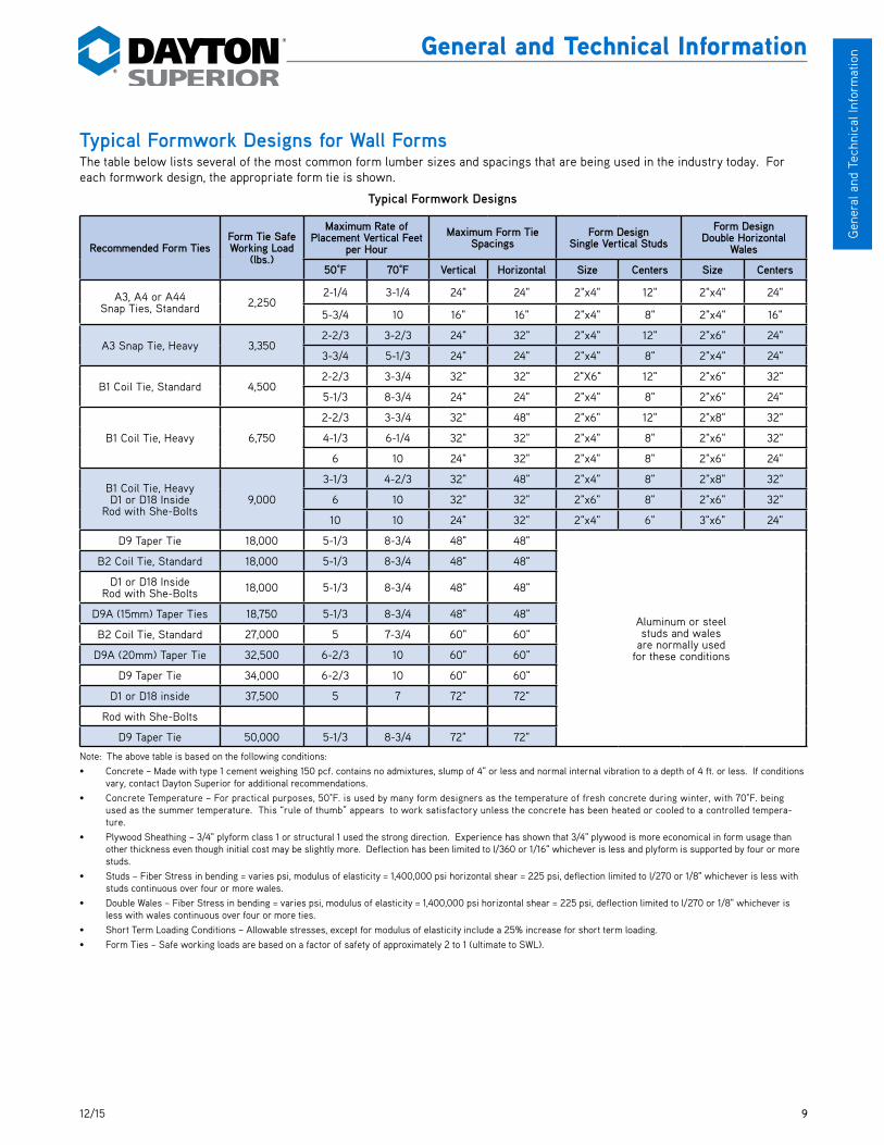
Typical Formwork Designs for Wall FormsThe table below lists several of the most common form lumber sizes and spacings that are being used in the industry today. For each formwork design, the appropriate form tie is shown.
Typical Formwork Designs
Recommended Form TiesForm Tie Safe Working Load
(lbs.)
Maximum Rate of Placement Vertical Feet
per HourMaximum Form Tie
SpacingsForm Design
Single Vertical StudsForm Design
Double Horizontal Wales
50°F 70°F Vertical Horizontal Size Centers Size Centers
A3, A4 or A44Snap Ties, Standard 2,250
2-1/4 3-1/4 24" 24" 2"x4" 12" 2"x4" 24"
5-3/4 10 16" 16" 2"x4" 8" 2"x4" 16"
A3 Snap Tie, Heavy 3,350 2-2/3 3-2/3 24" 32" 2"x4" 12" 2"x6" 24"
3-3/4 5-1/3 24" 24" 2"x4" 8" 2"x4" 24"
B1 Coil Tie, Standard 4,500 2-2/3 3-3/4 32" 32" 2"X6" 12" 2"x6" 32"
5-1/3 8-3/4 24" 24" 2"x4" 8" 2"x6" 24"
B1 Coil Tie, Heavy 6,750
2-2/3 3-3/4 32" 48" 2"x6" 12" 2"x8" 32"
4-1/3 6-1/4 32" 32" 2"x4" 8" 2"x6" 32"
6 10 24" 32" 2"x4" 8" 2"x6" 24"
B1 Coil Tie, HeavyD1 or D18 Inside
Rod with She-Bolts9,000
3-1/3 4-2/3 32" 48" 2"x4" 8" 2"x8" 32"
6 10 32" 32" 2"x6" 8" 2"x6" 32"
10 10 24" 32" 2"x4" 6" 3"x6" 24"
D9 Taper Tie 18,000 5-1/3 8-3/4 48" 48"
Aluminum or steel studs and wales
are normally used for these conditions
B2 Coil Tie, Standard 18,000 5-1/3 8-3/4 48" 48"
D1 or D18 InsideRod with She-Bolts 18,000 5-1/3 8-3/4 48" 48"
D9A (15mm) Taper Ties 18,750 5-1/3 8-3/4 48" 48"
B2 Coil Tie, Standard 27,000 5 7-3/4 60" 60"
D9A (20mm) Taper Tie 32,500 6-2/3 10 60" 60"
D9 Taper Tie 34,000 6-2/3 10 60" 60"
D1 or D18 inside 37,500 5 7 72" 72"
Rod with She-Bolts
D9 Taper Tie 50,000 5-1/3 8-3/4 72" 72"
Note: The above table is based on the following conditions:• Concrete – Made with type 1 cement weighing 150 pcf. contains no admixtures, slump of 4" or less and normal internal vibration to a depth of 4 ft. or less. If conditions
vary, contact Dayton Superior for additional recommendations.• Concrete Temperature – For practical purposes, 50°F. is used by many form designers as the temperature of fresh concrete during winter, with 70°F. being
used as the summer temperature. This “rule of thumb” appears to work satisfactory unless the concrete has been heated or cooled to a controlled tempera-ture.
• Plywood Sheathing – 3/4" plyform class 1 or structural 1 used the strong direction. Experience has shown that 3/4" plywood is more economical in form usage than other thickness even though initial cost may be slightly more. Deflection has been limited to l/360 or 1/16" whichever is less and plyform is supported by four or more studs.
• Studs – Fiber Stress in bending = varies psi, modulus of elasticity = 1,400,000 psi horizontal shear = 225 psi, deflection limited to l/270 or 1/8" whichever is less with studs continuous over four or more wales.
• Double Wales – Fiber Stress in bending = varies psi, modulus of elasticity = 1,400,000 psi horizontal shear = 225 psi, deflection limited to l/270 or 1/8" whichever is less with wales continuous over four or more ties.
• Short Term Loading Conditions – Allowable stresses, except for modulus of elasticity include a 25% increase for short term loading.• Form Ties – Safe working loads are based on a factor of safety of approximately 2 to 1 (ultimate to SWL).

10 12/15
General and Technical Inform
ation
General and Technical Information
Vertical Formwork Design LoadsThe selection of the proper sheathing, studs and/or wales for concrete formwork requires knowledge of maximum lateral pressure which will be exerted by the concrete. Dayton Superior is in agreement with the Lateral Pressure Design Formulas contained in the American Concrete Institute’s “Guide to Formwork for Concrete”, (ACI 347 latest revision). Designers of formwork for concrete walls or columns find the following information useful:
• For general purpose conditions and unless the special conditions listed below are met, all formwork should be designed for the lateral pressure of the newly placed concrete using the formula of:
P = W x H
Where P = lateral pressure, lbs/sq ft;
W = unit weight of fresh concrete, lbs per cu ft or 150 pcf for normal weight concrete;
H = depth of fluid or plastic concrete in feet. (Normally height of wall or column form.)
Please note that the maximum and minimum values given for the formulas under the special conditions do not apply to the above lateral pressure formula.
• Special Condition No. 1 — For concrete made with type 1 cement, weighing 150 lbs per cu ft, containing no pozzolans or admixtures, having a slump of 4" or less and normal internal vibration to a depth of 4 ft. or less. Then the formwork may be designed for a lateral pressure as follows:
For columns:
P = 150 + 9,000 x R
T
with a maximum of 3,000 lbs per sq ft, a minimum of 600 lbs per sq ft, but in no case greater than W x H.
For walls with a rate of placement less than 7 ft. per hour:
P = 150 + 9,000 x R
T
with a maximum of 2,000 lbs per sq ft, a minimum of 600 lbs per sq ft, but in no case greater than W x H.
For walls with a rate of placement of over 7 ft. / hour but less than 10 ft. / hour:
P = 150 + 43,400 + 2800 x R
T T
with a maximum of 2,000 lbs per sq ft, a minimum of 600 lbs per sq ft, but in no case greater that W x H.
Where P = lateral pressure, lbs per sq ft;
R = rate of placement, feet per hour, and
T = temperature of concrete in the form, degree fahrenheit. For practical purposes, 50°F. is used by many form designers as the temperature of fresh concrete during the winter, with 70°F. being used as the summer temperature. This “rule of thumb” appears to work satisfactorily unless the concrete has been heated or cooled to a controlled temperature.
• Special Condition No. 2 — If concrete is to be pumped from the base of the form, the form should be designed for a full hydro-static head of concrete (W x H) plus a minimum allowance of 25% for pump surge pressure. In certain instances pressures may be as high as the face pressure of the pump piston.
• Special Condition No. 3 — Caution must be taken when using external vibration or concrete made with shrinkage compensat-ing or expansive cements. Pressure in excess of equivalent hydrostatic may occur.
Wall forms must meet wind load requirements of American National Standards Institute A-58.1 (Reference to section 2-6) or of the local building code, whichever is more stringent. The minimum wind design load must be 15 lbs per sq ft. Bracing for wall forms must also be designed for a horizontal load of at least 100 lbs per lineal ft of wall applied at the top of the form.
Lateral Pressure of Concrete for General Purpose Conditions
Depth of Fluid or Plastic Concrete
Pounds Per Square Foot in Feet
4 6005 7506 9007 1,0508 1,2009 1,35010 1,50012 1,80014 2,10016 2,40018 2,70020 3,000
Lateral Pressure of Concrete for Special Condition No. 1 – WallsRate of
Placement Feet Per
Hour
Pounds per Square Foot for Indicated Temperature
50° 70°2 600 6003 690 6004 870 6645 1,050 7936 1,230 9217 1,410 1,0508 1,466 1,0909 1,522 1,13010 1,578 1,170
Note: Do not use lateral pressures in excess of 150 x height of fluid or plastic concrete in forms.

1112/15
Gen
eral
and
Tec
hnic
al In
form
atio
nGeneral and Technical Information
Points to Remember
Slab Formwork Design LoadsThe loadings used in the designs of slab formwork consists of a dead load and a live load. The weight of the formwork plus the concrete is considered dead load while the live load is made up of the weight of workers, equipment, material storage and other like items which is supported by the formwork. The tables below tabulate design loads based on the concrete weight for the thicknesses indicated, and includes 10 pounds per square foot for the weight of forms and a live load of 50 or 75 pounds per square foot as indi-cated. A live load of 75 pounds per square foot is generally used when motorized carts are used to transport concrete during the placing operation.
Slab Formwork Design Load for Uniform Slab Thickness(Includes 50 psf Live Load)
Pounds per Square Foot for Indicated Thickness2" 4" 6" 8" 10" 12" 14" 16" 18" 20"
100 110 135 160 185 210 235 260 285 310
(Includes 75 psf Live Load) Pounds per Square Foot for Indicated Thickness
2" 4" 6" 8" 10" 12" 14" 16" 18" 20"
125* 135 160 185 210 235 260 285 310 335
Note: Chart is based on a concrete weight of 150 pounds per cubic foot.* ACI 347 recommends a minimum 100 psf for form design or 125 psf if motorized carts are used.
For a complete explanation of general objectives in formwork design, planning, materials and accessories, loads and pressures, design tables and much more, it is recommended that a copy of ACI publication SP-4 “Formwork for Concrete” be obtained. The current edition is available from American Concrete Institute, P.O. Box 9094, Farmington Hills, MI 48333. Website: www.concrete.org.
6" 12" 24"
150 lbs. 150 lbs. 150 lbs.
FT87654321
150 lbs.
300
450
600
750
900
1050
1200
150 lbs.
300
450
600
150 lbs.
300
450
600
150 lbs.
300
450
750
FT.54321
With all concretein fluid or
plastic state
As bottomfoot sets up
As second foot oconcrete hard
13/4 HR. 1 HR.
70°�40°� FT.�8�7�6�5�4�3�2�1
Fluid or plastic concrete exerts the same side pressure on forms regard-less of their width.
As you add more fluid or plastic concrete to forms, the pressure will build up toward the bottom at about the rate of 150 pounds per foot of depth. This will be true as long as all con-crete remains in a plastic state.
Example: Eight feet of fluid or plastic concrete bears on the bottom foot of forms with a pres-sure of 8 x 150 pounds or 1200 pounds per square foot.
As concrete hardens, lateral pressure on forms decreases.
Concrete sets up or hardens faster with an increase in temperature.
Example: At 70°F. con-crete sets in approxi-mately 1 hour. At 40°F concrete will set up in about 1-3/4 hours.
With all concrete in fluid or
plastic state
As second foot of conrete hardens
As bottom foot sets up

12 12/15
General and Technical Inform
ation
General and Technical Information
Technical Data–PlywoodData is based on information supplied by the American Plywood Association (APA). The recommended spacings listed in the fol-lowing table are for Plyform Class 1 or STRUCTURAL 1 Plyform. Plyform is a special exterior type of plywood designed by APA for use in formwork for concrete construction.
Though not manufactured specifically for concrete forming, grades other than Plyform have been used in formwork. The spacings shown in the table give a good estimate of performance for sanded grades such as APA A-C Exterior, APA B-C Exterior and unsanded grades such as APA RATED SHEATHING Exterior and Exposure 1 (CDX) (marked PSI), provided the plywood is used in the same direc-tion only.
For additional information on APA Plyform, please contact the American Plywood Association, P.O. Box 11700, Tacoma, WA 98411.
Plywood Used Strong Way Face Grain Across Supports
Plywood Used Weak Way Face Grain Along Supports
Curved Forms: Plyform can be used for building curved forms. However, the following radii have been found to be appropriate minimums for mill run panels of the thicknesses shown, when bent dry. An occasional panel may develop localized failure at these radii.
Joists or Studs
Joist orStud
Spacing
Plywood
Joist orStud
Spacing
Joist orStud
Spacing
Joist or Stud Spacing Supports
Joist or Stud Spacing Supports
Safe Spacing in inches of Support for Plyform Sheathing Continuous Over Four or More Supports
Design Load of Concrete Pounds Per
Sq. Ft.
Fb = 1,930 psi; Rolling Shear = 72 psi E = 1,500,000 psi
Plyform Used Weak Way Plyform Used Strong Way
19/32" 5/8" 23/32" 3/4" 19/32" 5/8" 23/32" 3/4"
100 13" 14" 17" 19" 20" 21" 23" 24"
125 12" 13" 16" 17" 19" 19" 22" 22"
150 11" 12" 15" 16" 17" 18" 20" 21"
175 10" 11" 14" 15" 17" 17" 19" 20"
200 10" 11" 14" 15" 16" 17" 18" 19"
225 10" 10" 13" 14" 15" 16" 18" 18"
250 9" 10" 13" 14" 15" 15" 17" 18"
275 9" 10" 12" 13" 14" 15" 17" 17"
300 9" 9" 12" 13" 14" 14" 16" 17"
350 8" 9" 11" 12" 13" 14" 15" 16"
400 8" 9" 11" 12" 13" 13" 15" 15"
500 7" 8" 10" 11" 12" 12" 14" 14"
600 7" 7" 9" 10" 11" 11" 13" 13"
700 6" 7" 9" 10" 10" 11" 12" 12"
800 6" 7" 8" 9" 10" 10" 11" 11"
900 6" 6" 7" 8" 9" 9" 10" 11"
1,000 5" 6" 7" 7" 9" 9" 10" 10"
1,200 5" 5" 6" 6" 8" 8" 9" 9"
1,400 4" 4" 5" 5" 7" 7" 8" 8"
1,600 4" 4" 5" 5" 6" 6" 8" 8"
1,800 4" 4" 4" 5" 6" 6" 7" 7"
2,000 3" 3" 4" 4" 5" 5" 6" 6"
Support spacings are governed by bending, shear or deflection. Maximum deflection ℓ/360 of spacing, but not more than 1/16". Contact Dayton Superior for safe spacing of supports when plyform is used over two or three supports.
Plywood Data
Plywood ThicknessApproximate Weight, lbs. Min. Bending Radii, ft.
4 x 8 Sheet Sq. Ft. Across Grain Parallel to Grain
1/4" 26 .8 2 5
5/16" 32 1.0 2 6
11/32" or 3/8" 35 1.1 3 8
15/32" or 1/2" 48 1.5 6 12
19/32" or 5/8" 58 1.8 8 16
23/32" or 3/4" 70 2.2 12 20
Joists or Studs Plywood
Supports
Supports
Joist or Stud Spacing
Joist or Stud Spacing
Joist or Stud Spacing
Joist or Stud Spacing
Joist or Stud Spacing

1312/15
Gen
eral
and
Tec
hnic
al In
form
atio
nGeneral and Technical Information
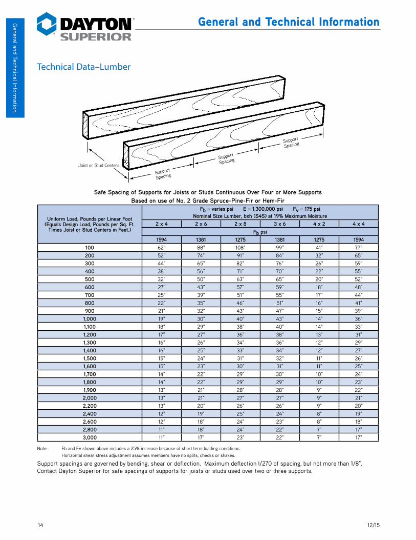
Technical Data–Lumber
Safe Spacing of Supports for Joists or Studs Continuous Over Four or More SupportsBased on use of No. 2 Grade Southern Pine or Douglas Fir-Larch
Uniform Load, Pounds per Linear Foot (Equals Design Load, Pounds per Sq. Ft. Times Joist or Stud Centers
in Feet.)
Fb = varies psi E = 1,400,000 psi Fv = 225 psiNominal Size Lumber, bxh (S4S) at 19% Maximum Moisture
2 x 4 2 x 6 2 x 8 3 x 6 4 x 2 4 x 4Fb psi
1625 1438 1313 1438 1438 1625100 64" 89" 110" 101" 42" 79"200 53" 75" 92" 85" 34" 66"300 45" 66" 83" 77" 27" 60"400 39" 57" 72" 72" 24" 56"500 35" 51" 64" 66" 21" 53"600 32" 47" 59" 60" 19" 48"700 29" 43" 54" 56" 18" 45"800 27" 40" 51" 52" 17" 42"900 25" 38" 48" 49" 16" 39"
1,000 23" 36" 45" 47" 15" 37"1,100 21" 34" 43" 44" 14" 36"1,200 20" 32" 42" 43" 14" 34"1,300 19" 30" 40" 41" 13" 33"1,400 18" 29" 38" 39" 13" 32"1,500 18" 28" 36" 38" 12" 30"1,600 17" 26" 35" 37" 12" 29"1,700 16" 26" 34" 35" 12" 29"1,800 16" 25" 33" 34" 11" 27"1,900 15" 24" 32" 33" 11" 26"2,000 15" 23" 31" 32" 11" 25"2,200 14" 22" 29" 30" 10" 24"2,400 14" 21" 28" 28" 10" 22"2,600 13" 21" 27" 27" 9" 21"2,800 13" 20" 26" 26" 9" 20"
3,000 12" 19" 25" 25" 8" 19"
Note: Fb and Fv shown above includes a 25% increase because of short term loading conditions. Horizontal shear stress adjustment assumes members have no splits, checks or shakes.
Support spacings are governed by bending, shear or deflection. Maximum deflection l/270 of spacing, but not more than 1/8". Contact Dayton Superior for safe spacings of supports for joists or studs used over two or three supports.
Joist or Stud Centers
Support�
Spacing
Support�
Spacing
Support�
Spacing
Support
Spacing
Support
Spacing
Support
Spacing
Joist or Stud Centers
14 12/15
General and Technical Inform
ation
General and Technical Information
Technical Data–Lumber
Safe Spacing of Supports for Joists or Studs Continuous Over Four or More SupportsBased on use of No. 2 Grade Spruce-Pine-Fir or Hem-Fir
Uniform Load, Pounds per Linear Foot (Equals Design Load, Pounds per Sq. Ft.
Times Joist or Stud Centers in Feet.)
Fb = varies psi E = 1,300,000 psi Fv = 175 psiNominal Size Lumber, bxh (S4S) at 19% Maximum Moisture
2 x 4 2 x 6 2 x 8 3 x 6 4 x 2 4 x 4Fb psi
1594 1381 1275 1381 1275 1594100 62" 88" 108" 99" 41" 77"200 52" 74" 91" 84" 32" 65"300 44" 65" 82" 76" 26" 59"400 38" 56" 71" 70" 22" 55"500 32" 50" 63" 65" 20" 52"600 27" 43" 57" 59" 18" 48"700 25" 39" 51" 55" 17" 44"800 22" 35" 46" 51" 16" 41"900 21" 32" 43" 47" 15" 39"
1,000 19" 30" 40" 43" 14" 36"1,100 18" 29" 38" 40" 14" 33"1,200 17" 27" 36" 38" 13" 31"1,300 16" 26" 34" 36" 12" 29"1,400 16" 25" 33" 34" 12" 27"1,500 15" 24" 31" 32" 11" 26"1,600 15" 23" 30" 31" 11" 25"1,700 14" 22" 29" 30" 10" 24"1,800 14" 22" 29" 29" 10" 23"1,900 13" 21" 28" 28" 9" 22"2,000 13" 21" 27" 27" 9" 21"2,200 13" 20" 26" 26" 9" 20"2,400 12" 19" 25" 24" 8" 19"2,600 12" 18" 24" 23" 8" 18"2,800 11" 18" 24" 22" 7" 17"3,000 11" 17" 23" 22" 7" 17"
Note: Fb and Fv shown above includes a 25% increase because of short term loading conditions. Horizontal shear stress adjustment assumes members have no splits, checks or shakes.
Support spacings are governed by bending, shear or deflection. Maximum deflection l/270 of spacing, but not more than 1/8". Contact Dayton Superior for safe spacings of supports for joists or studs used over two or three supports.
Joist or Stud Centers
Support�
Spacing
Support�
Spacing
Support�
Spacing
Support
Spacing
Support
Spacing
Support
Spacing
Joist or Stud Centers

1512/15
Gen
eral
and
Tec
hnic
al In
form
atio
nGeneral and Technical Information
Technical Data–Lumber
Safe Spacing of Supports for Double Ledgers or Wales Continuous Over Four or More Supports Based on use of No. 2 Grade Southern Pine or Douglas Fir-Larch
Uniform Load, Pounds per Linear Foot (Equals Design Load, Pounds per Sq. Ft. Times Ledger or Wale Centers in Feet.)
Fb = varies psi E = 1,400,000 psi Fv = 225 psiNominal Size Lumber, bxh (S4S) at 19% Maximum Moisture
Double 2 x 4
Double 2 x 6
Double 2 x 8
Double 3 x 6
Double 3 x 8
Fb psi 1625 1438 1313 1438 1313
1,000 35" 51" 64" 66" 83" 1,100 33" 49" 61" 63" 79" 1,200 32" 47" 59" 60" 76" 1,300 30" 45" 56" 58" 73" 1,400 29" 43" 54" 56" 70" 1,500 28" 42" 53" 54" 68" 1,600 27" 40" 51" 52" 66" 1,700 26" 39" 49" 51" 64" 1,800 25" 38" 48" 49" 62" 1,900 24" 37" 47" 48" 60" 2,000 23" 36" 45" 47" 59" 2,200 21" 34" 43" 44" 56" 2,400 20" 32" 42" 43" 54" 2,600 19" 30" 40" 41" 51" 2,800 18" 29" 38" 39" 50" 3,000 18" 28" 36" 38" 48" 3,200 17" 26" 35" 37" 46" 3,400 16" 26" 34" 35" 45" 3,600 16" 25" 33" 34" 44" 3,800 15" 24" 32" 33" 43" 4,000 15" 23" 31" 32" 42"
Note: Fb and Fv shown above includes a 25% increase because of short term loading conditions. Horizontal shear stress adjustment assumes members have no splits, checks or shakes.
Support spacings are governed by bending, shear or deflection. Maximum deflection ℓ/270 of spacing, but not more than 1/8". Contact Dayton Superior for safe spacings of supports for joists or studs used over two or three supports.
Wale or Ledger Centers
Support�
Spacing
Support�
Spacing
Support�
Spacing
Support
Spacing
Support
Spacing
Support
Spacing
Wale or Ledger Centers

16 12/15
General and Technical Inform
ation
General and Technical Information
Technical Data–Lumber
Safe Spacing of Supports for Double Ledgers or Wales Continuous Over Four or More Supports Based on use of No. 2 Grade Spruce-Pine-Fir or Hem-Fir
Uniform Load, Pounds per Linear Foot (Equals Design Load, Pounds per Sq. Ft. Times Ledger or Wale Centers in Feet.)
Fb = varies psi E = 1,300,000 psi Fv = 175 psiNominal Size Lumber, bxh (S4S) at 19% Maximum Moisture
Double 2 x 4
Double 2 x 6
Double 2 x 8
Double 3 x 6
Double 3 x 8
Fb psi 1594 1381 1275 1381 1275
1,000 32" 50" 63" 65" 82" 1,100 29" 46" 60" 62" 78" 1,200 27" 43" 57" 59" 75" 1,300 26" 41" 54" 57" 72" 1,400 25" 39" 51" 55" 69" 1,500 23" 37" 48" 53" 67" 1,600 22" 35" 46" 51" 65" 1,700 21" 34" 44" 49" 63" 1,800 21" 32" 43" 47" 61" 1,900 20" 31" 41" 45" 59" 2,000 19" 30" 40" 43" 57" 2,200 18" 29" 38" 40" 53" 2,400 17" 27" 36" 38" 50" 2,600 16" 26" 34" 36" 47" 2,800 16" 25" 33" 34" 45" 3,000 15" 24" 31" 32" 43" 3,200 15" 23" 30" 31" 41" 3,400 14" 22" 29" 30" 39" 3,600 14" 22" 29" 29" 38" 3,800 13" 21" 28" 28" 37" 4,000 13" 21" 27" 27" 36"
Note: Fb and Fv shown above includes a 25% increase because of short term loading conditions. Horizontal shear stress adjustment assumes members have no splits, checks or shakes.
Support spacings are governed by bending, shear or deflection. Maximum deflection l/270 of spacing, but not more than 1/8". Contact Dayton Superior for safe spacings of supports for joists or studs used over two or three supports.
Wale or Ledger Centers
Support�
Spacing
Support�
Spacing
Support�
Spacing
Support
Spacing
Support
Spacing
Support
Spacing
Wale or Ledger Centers
1712/15
Gen
eral
and
Tec
hnic
al In
form
atio
nGeneral and Technical Information
Technical Data–Lumber
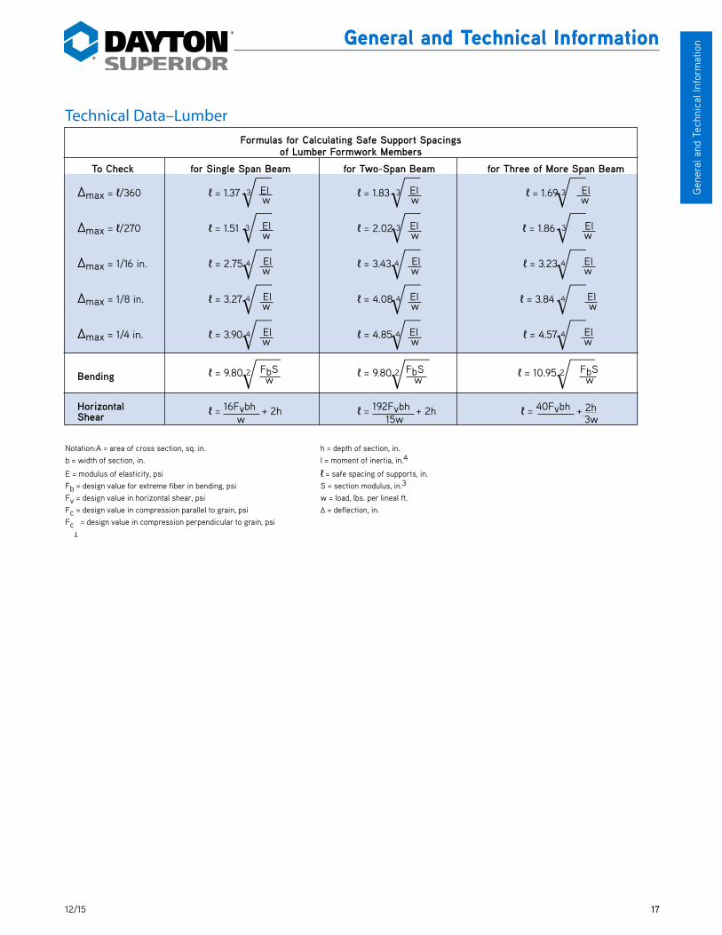
Notation:A = area of cross section, sq. in. h = depth of section, in. b = width of section, in. l = moment of inertia, in.4
E = modulus of elasticity, psi ℓ = safe spacing of supports, in. Fb = design value for extreme fiber in bending, psi S = section modulus, in.3 Fv = design value in horizontal shear, psi w = load, lbs. per lineal ft. Fc = design value in compression parallel to grain, psi ∆ = deflection, in. Fc = design value in compression perpendicular to grain, psi
Formulas for Calculating Safe Support Spacings of Lumber Formwork Members
To Check for Single Span Beam for Two-Span Beam for Three of More Span Beam
∆max = ℓ/360 ℓ = 1.37 3 El ℓ = 1.83 3 El ℓ = 1.69 3 El w w w
∆max = ℓ/270 ℓ = 1.51 3 El ℓ = 2.02 3 El ℓ = 1.86 3 El w w w
∆max = 1/16 in. ℓ = 2.75 4 El ℓ = 3.43 4 El ℓ = 3.23 4 El w w w
∆max = 1/8 in. ℓ = 3.27 4 El ℓ = 4.08 4 El ℓ = 3.84 4 El w w w
∆max = 1/4 in. ℓ = 3.90 4 El ℓ = 4.85 4 El ℓ = 4.57 4 El w w w
Bending ℓ = 9.80 2 FbS ℓ = 9.80 2 FbS ℓ = 10.95 2 FbS w w w
Horizontal ℓ = 16Fvbh + 2h ℓ = 192Fvbh + 2h ℓ = 40Fvbh + 2h Shear w 15w 3w
T

18 12/15
General and Technical Inform
ation
General and Technical Information
Technical Data–Lumber
*Rough dry sizes are 1/8 in. larger, both dimensions.Properties and weights of American Standard Board, Dimension and Timber sizes commonly used for formwork construction are based on data supplied by the National Forest Products Association.Approximate weights listed are based on lumber weighing 35 lbs. per cubic foot.
Properties of Structural Lumber
Nominal Size in Inches,
bxh
American Standard Sizes in
Inches, bxh S4S*
19% Maximum Moisture
Area of section A = bh, sq. in.
Moment of Inertia, in.4 l = bh3 12
Section Modulus, in.3
S = bh2 6
Board Feet per Lineal Foot of Piece
Approx. Weight
per Lineal Foot (lbs.) of SAS Lumber
Rough S4S Rough S4S Rough S4S Rough S4S4x1 3-1/2 x 3/4 3.17 2.62 0.20 0.12 0.46 0.33 1/3 .76x1 5-1/2 x 3/4 4.92 4.12 0.31 0.19 0.72 0.52 1/2 1.08x1 7-1/4 x 3/4 6.45 5.44 0.41 0.25 0.94 0.68 2/3 1.410x1 9-1/4 x 3/4 8.20 6.94 0.52 0.32 1.20 0.87 5/6 1.712x1 11-1/4 x 3/4 9.95 8.44 0.63 0.39 1.45 1.05 1 2.14x2 3-1/2 x 1-1/2 5.89 5.25 1.30 0.98 1.60 1.31 2/3 1.36x2 5-1/2 x 1-1/2 9.14 8.25 2.01 1.55 2.48 2.06 1 2.08x2 7-1/4 x 1-1/2 11.98 10.87 2.64 2.04 3.25 2.72 1-1/3 2.710x2 9-1/4 x 1-1/2 15.23 13.87 3.35 2.60 4.13 3.47 1-2/3 3.412x2 11-1/4 x 1-1/2 18.48 16.87 4.07 3.16 5.01 4.21 2 4.12x4 1-1/2 x 3-1/2 5.89 5.25 6.45 5.36 3.56 3.06 2/3 1.32x6 1-1/2 x 5-1/2 9.14 8.25 24.10 20.80 8.57 7.56 1 2.0 2x8 1-1/2 x 7-1/4 11.98 10.87 54.32 47.63 14.73 13.14 1-1/3 2.72x10 1-1/2 x 9-1/4 15.23 13.87 111.58 98.93 23.80 21.39 1-2/3 3.42x12 1-1/2 x 11-1/4 18.48 16.87 199.31 177.97 35.04 31.64 2 4.1 3x4 2-1/2 x 3-1/2 9.52 8.75 10.42 8.93 5.75 5.10 1 2.23x6 2-1/2 x 5-1/2 14.77 13.75 38.93 34.66 13.84 12.60 1-1/2 3.43x8 2-1/2 x 7-1/4 19.36 18.12 87.74 79.39 23.80 21.90 2 4.43x10 2-1/2 x 9-1/4 24.61 23.12 180.24 164.89 38.45 35.65 2-1/2 5.73x12 2-1/2 x 11-1/4 29.86 28.12 321.96 296.63 56.61 52.73 3 6.94x4 3-1/2 x 3-1/2 13.14 12.25 14.39 12.50 7.94 7.15 1-1/3 3.04x6 3-1/2 x 5-1/2 20.39 19.26 53.76 48.53 19.12 17.65 2 4.74x8 3-1/2 x 7-1/4 26.73 25.38 121.17 111.15 32.86 30.66 2-2/3 6.24x10 3-1/2 x 9-1/4 33.98 32.38 248.91 230.84 53.10 49.91 3-1/3 7.96x3 5-1/2 x 2-1/2 14.77 13.75 8.48 7.16 6.46 5.73 1-1/2 3.46x4 5-1/2 x 3-1/2 20.39 19.25 22.33 19.65 12.32 11.23 2 4.76x6 5-1/2 x 5-1/2 31.64 30.25 83.43 76.26 29.66 27.73 3 7.46x8 5-1/2 x 7-1/2 42.89 41.25 207.81 193.36 54.51 51.56 4 10.08x8 7-1/2 x 7-1/2 58.14 56.25 281.69 263.67 73.89 70.31 5-1/3 13.7
Xh
b
X
X–X Neutral Axis
b
b
X X Xh X h
X–X Neutral Axis

1912/15
Ligh
t For
min
g P
rodu
cts
Light Forming
A2 Plastic ConesDayton Superior A2 Plastic Cones can be added to A3, A4 and A44 Snap Ties and A46 and A48 Loop Ties. The cones act as inter-nal spreaders, reduce grout leakage and aid in the breakback operation.
A2 Plastic Cones are recommended when specifications require a nominal 1", 1-1/2", 2" or greater breakback. Breakback is approxi-mately 3/16" less than the cone length.
Note: Plastic Cones are designed to act as internal form spreaders only. They are not intended to support loads applied by personal fail arrest systems and/or scaffold brackets.
A3 Standard Snap TieDayton Superior A3 Standard Snap Ties are manufactured with either hot or cold forged integral heads. A3 snap ties have a nominal 1" breakback with 1/4" and 1/2" breakbacks available on special order. Breakbacks over 1" can be provided on special order, but due to the increased concrete bond, Dayton Superior cannot guarantee that the ties will consistently provide proper breakback. Coating the tie ends with wax will aid in breakback operation.
Each A3 snap tie is fabricated with flats or crimps to prevent the snap tie from turning in the con-crete during breakback operations. A3 Snap Ties are available with fixed metal spreader washers.
All snap ties can be manufactured with a tight fitting neoprene washer located near the center of the tie. The water resistant snap tie is designed to help eliminate water seepage along the tie by breaking the surface continuity of the wire.
Drill holes in plywood 1/8" larger than the Snap Tie head. Normally, a 5/8" drill bit is sufficient.
A2 Plastic Cone Selection ChartDiameter Length
3/4" 1", 1-1/2"
1" 1", 1-1/2" 2"
1-1/4" 1-1/2"
Lumber�and�
Wedge
Break Back
Wall�Thickness
Lumber�and�
Wedge
2,250 lbs.Safe Working Load
A3 Snap Ties
To Order:Specify: (1) quantity, (2) name, (3) wall thickness, (4) lumber and wedge dimension (allow 1/2" for wedge take up), (5) break back.
Example:3,00 pcs. A3 Standard Snap Tie, 18" wall, 8-1/4" L&W, 1" break back.
SWL provides a factor of safety of approximately 2 to 1.
5/8" O.D. x 1/8" ThickNeoprene Water Resistant Washer
A2 Plastic Cone
Maximum �Diameter
LengthLength
Maximum Diameter
Wall Thickness
Lumber and
Wedge
Lumber and
Wedge
Breakback
Breakback15/16" Diameter Metal Spreader Washer
15/16" Diameter Metal Spreader Washer
Bead Locates Spreader Washer
Bead Locates Spreader Washer
Cold Formed Head on Stock Sizes
Hot Formed Head on Stock Sizes
Anti-Turn Feature (Flat or Crimp)
Anti-Turn Feature (Flat or Crimp)
Breakback

20 12/15
Light Forming P
roducts
Light Forming
A3 Heavy Snap TieDayton Superior A3 Heavy Snap Ties are used when a higher safe working load is required. The A3 snap tie is manufactured with cold forged integral heads and is equipped with flats or crimps to prevent turning.
See A3 Snap Tie for additional pertinent information on breakback and fixed metal washers.
A3 Stayform TieA3 Stayform Ties are manufactured with a standard forged head on one end and nut and plate on another end. They are used for connecting site-built wood forms to vertical rebar for blind-side wall applications. For use with the A110 Metal Rib.
• Low cost solution for blindside wall application
• A3 Stayform Ties are made with standard 1" breakback
• Ultimate load is 3,750 lbs.
• The largest rebar diameter for A3 Stayform Ties is #8
• Available with plastic cone
• Available in any length from 6" to 48"
A3B1 Combination TieA3B1 Combination Ties are manufactured with a standard forged head on one end and 1/2" coil tie on another. A3B1 Combination Ties are used for connecting site-built wood forms to coil rod for blind-side wall application.
• Low cost solution for blindside wall application
• Available in any length from 7" to 36"
• Ultimate load is 4,500 lbs.
• Available with plastic cone or loose washer
3,350 lbs.Safe Working Load
Bead Locates Spreader�Washer
Cold Formed Head
Anti-Turn Feature�(Flat or Crimp)
Break Back 15/16" Diameter Metal Spreader Washer
A3 Heavy Snap Tie
To Order:Specify: (1) quantity, (2) name, (3) wall thickness, (4) lumber and wedge dimension (allow 1/2" for wedge take up), (5) break back.
Example:3,00 pcs. A3 Heavy Snap Tie, 18" wall, 8-1/4" L&W, 1" break back
SWL provides a factor of safety of approximately 2 to 1.
15/16" Diameter Metal Spreader Washer
Bead Locates Spreader Washer Cold Formed Head
Anti-Turn Feature (Flat or Crimp) Breakback
2112/15
Ligh
t For
min
g P
rodu
cts
Light Forming
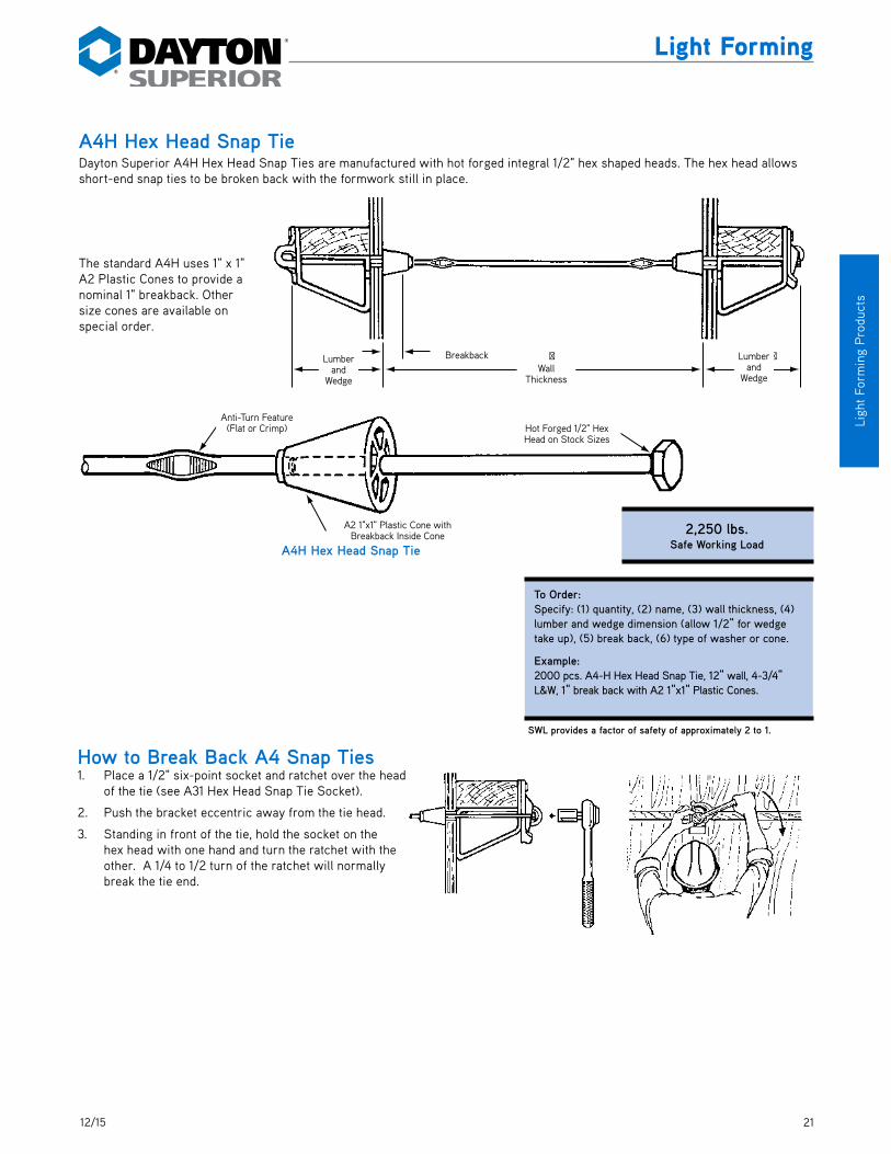
A4H Hex Head Snap TieDayton Superior A4H Hex Head Snap Ties are manufactured with hot forged integral 1/2" hex shaped heads. The hex head allows short-end snap ties to be broken back with the formwork still in place.
The standard A4H uses 1" x 1" A2 Plastic Cones to provide a nominal 1" breakback. Other size cones are available on special order.
Lumber�and�
Wedge
�Wall�
Thickness
Break Back Lumber�and�
Wedge
To Order:Specify: (1) quantity, (2) name, (3) wall thickness, (4) lumber and wedge dimension (allow 1/2" for wedge take up), (5) break back, (6) type of washer or cone.
Example:2000 pcs. A4-H Hex Head Snap Tie, 12" wall, 4-3/4" L&W, 1" break back with A2 1"x1" Plastic Cones.
SWL provides a factor of safety of approximately 2 to 1.
Wall Thickness
Lumber and
Wedge
Lumber and
Wedge
Breakback
How to Break Back A4 Snap Ties1. Place a 1/2" six-point socket and ratchet over the head
of the tie (see A31 Hex Head Snap Tie Socket).
2. Push the bracket eccentric away from the tie head.
3. Standing in front of the tie, hold the socket on the hex head with one hand and turn the ratchet with the other. A 1/4 to 1/2 turn of the ratchet will normally break the tie end.
Hot Forged 1/2" Hex �Head on Stock Sizes
Anti-Turn Feature�(Flat or Crimp)
A-2 1" x 1" Plastic Cone�with Break Back Inside Cone
A4H Hex Head Snap Tie
A2 1"x1" Plastic Cone with Breakback Inside Cone
Hot Forged 1/2" Hex Head on Stock Sizes
Anti-Turn Feature (Flat or Crimp)
2,250 lbs.Safe Working Load

22 12/15
Light Forming P
roducts
Light Forming
A5 Threaded PullOut TieDayton Superior A5 Threaded PullOut Tie is manufactured with a standard forged head on one end and 2" of 1/4" - 28 UNF-2A thread on the opposite end. Washers and nut are supplied loose and are placed on the tie after the tie has been installed through the form plywood.
Note: The A5 Threaded PullOut Tie needs to be coated with a form release agent or a water resistant grease, before the concrete is placed, to facilitate tie removal.
To remove the A5 tie from the set concrete, one end of the tie must be cut off between the plywood and the wales and then extracted by pulling on the oppo-site end.
A6 Spandrel Point Tie
Dayton Superior A6 Spandrel Point Tie is available for tying light outside spandrel beam forms. One end is fabricated with a standard end with any style plastic cone or spreader washer. The opposite end is bent 90˚ with a chisel point that is driven into the deck formwork. Breakback dimension is the same as standard snap ties.
Dayton Superior recommends placing a 1-1/4" fence staple over the tie within 1" of the bend.
W aleand
W edge
Dimension Inside to Inside of W ales(Equals W all Thickness 2 TimesStud Width + 2 Times Plywood Thickness)
W asher is Supplied Loosis to be Placed onto thTieAfter the Tie has been InstThrough the Plywood.
W ale+
1-1/2"
To Order:Specify: (1) quantity, (2) name, (3) fixed end = wale and wedge dimension (allow 1/2" for wedge take up), (4) dimension inside to inside of wales, (5) threaded end = wale + 1-1/2", (6) with or without spreader washers.
Example:2100 pcs. A5 Threaded PullOut Tie, 4" fixed end dimension, 20-1/2" inside to inside of wales, 5" threaded end, with spreader washers.
SWL provides a factor of safety of approximately 2 to 1.
Lumber�and�
Wedge
Beam�Width
Break Back
Fence Staple
Standard�3"
250 lbs.Safe Working Load
1,875 lbs.Safe Working Load
To Order:Specify: (1) quantity, (2) name, (3) beam thickness, (4) lumber and wedge (5) type of form spreaders and break back.
Example:400 pcs. A6 Spandrel Point Tie, 12" beam thickness, 8-1/4" L&W, (3" automatically added to beam thickness) with A2 1"x1" Plastic Cones and 1" break back.
SWL provides a factor of safety of approximately 2 to 1. Safe Working Load is controlled by wood spreader.
Beam Width Standard 3"
Lumber and
Wedge
Breakback
Fence Staple
Washer is Supplied Loose and is Placed on the Tie After the Tie has been Installed Through the
Plywood
Wale and
Wedge
Wale and
Wedge
Dimension Inside to Inside of Wales (Equals Wall Thickness 2 times Stud Width
+ 2 Times Plywood Thickness
2312/15
Ligh
t For
min
g P
rodu
cts
Light Forming
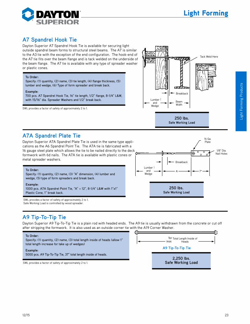
A7 Spandrel Hook TieDayton Superior A7 Spandrel Hook Tie is available for securing light outside spandrel beam forms to structural steel beams. The A7 is similar to the A3 tie with the exception of the end configuration. The hook-end of the A7 tie fits over the beam flange and is tack welded on the underside of the beam flange. The A7 tie is available with any type of spreader washer or plastic cones.
A7A Spandrel Plate TieDayton Superior A7A Spandrel Plate Tie is used in the same type appli-cations as the A6 Spandrel Point Tie. The A7A tie is fabricated with a 16 gauge steel plate which allows the tie to be nailed directly to the deck formwork with 6d nails. The A7A tie is available with plastic cones or metal spreader washers.
A9 Tip-To-Tip TieDayton Superior A9 Tip-To-Tip Tie is a plain rod with headed ends. The A9 tie is usually withdrawn from the concrete or cut off after stripping the formwork. It is also used as an outside corner tie with the A19 Corner Washer.
To Order:Specify: (1) quantity, (2) name, (3) tie length, (4) flange thickness, (5) lumber and wedge, (6) Type of form spreader and break back.
Example:700 pcs. A7 Spandrel Hook Tie, 16" tie length, 1/2" flange, 8-1/4" L&W, with 15/16" dia. Spreader Washers and 1/2" break back.
250 lbs.Safe Working Load
Lumber�and�
Wedge
Tack Weld Here
Beam�Width
Break �Back
Lumber�and�
WedgeA
Break �Back
1/8" Dia.�Nail Holes
16 Ga.�Plate
7"
250 lbs.Safe Working Load
SWL provides a factor of safety of approximately 2 to 1.
To Order:Specify: (1) quantity, (2) name, (3) “A” dimension, (4) lumber and wedge, (5) type of form spreaders and break back.
Example:1000 pcs. A7A Spandrel Point Tie, “A” = 12", 8-1/4" L&W with 1"x1" Plastic Cone, 1" break back.
SWL provides a factor of safety of approximately 2 to 1. Safe Working Load is controlled by wood spreader.
Total Length�inside of heads
To Order:Specify: (1) quantity, (2) name, (3) total length inside of heads (allow 1" total length increase for take up of wedges)
Example:5000 pcs. A9 Tip-To-Tip Tie, 37" total length inside of heads.
2,250 lbs. Safe Working Load
A9 Tip-To-Tip Tie
SWL provides a factor of safety of approximately 2 to 1.
Beam Width
Lumber and
Wedge
Breakback
Tack Weld Here
Lumber and
Wedge
Breakback
Total Length Inside of Heads
16 Ga. Plate
1/8" Dia. Nail Holes
24 12/15
Light Forming P
roducts
Light Forming
A10 Plate TieDayton Superior A10 Plate Tie is a plain rod with headed ends and square washers.
A13 Metal StrappingDayton Superior A13 Metal Stapping is used to fabricate and reinforce unusual forming requirements on the job site. The 300' roll is 3/4" wide 25 gauge steel.
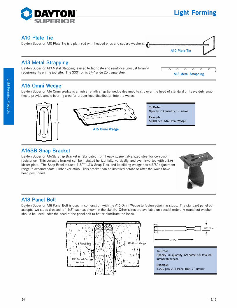
A16 Omni WedgeDayton Superior A16 Omni Wedge is a high strength snap tie wedge designed to slip over the head of standard or heavy duty snap ties to provide ample bearing area for proper load distribution into the wales.
A16SB Snap BracketDayton Superior A16SB Snap Bracket is fabricated from heavy guage galvanized steel for corrosion resistance. This versatile bracket can be installed horizontally, vertically, and even inverted with a 2x4 kicker plate. The Snap Bracket uses 4-3/4" L&W Snap Ties, and its sliding wedge has a 5/8" adjustment range to accommodate lumber variation. This bracket can be installed before or after the wales have been positioned.
A18 Panel BoltDayton Superior A18 Panel Bolt is used in conjunction with the A16 Omni Wedge to fasten adjoining studs. The standard panel bolt accepts two studs dressed to 1-1/2" each as shown in the sketch. Other sizes are available on special order. A round cut washer should be used under the head of the panel bolt to better distribute the loads.
6-1/8"
A16 Omni Wedge
To Order:Specify: (1) quantity, (2) name.
Example:5,000 pcs. A16 Omni Wedge.
A16 Omni W edgeA18 Panel Bolt
1/2" RoundCut W asher
3-1/2"
1/2" Nom.
To Order:Specify: (1) quantity, (2) name, (3) total net lumber thickness.
Example:5,000 pcs. A18 Panel Bolt, 3" lumber.
A13 Metal Strapping
A10 Plate Tie
A18 Panel Bolt
1/2" Round Cut Washer
A16 Omni Wedge

2512/15
Ligh
t For
min
g P
rodu
cts
Light Forming
A19 Corner WasherDayton Superior A19 Corner Washer is fabricated from 3/16" x 3" flat stock bent to form a wedge block. The ample bearing flanges are drilled for nailing to the wales. The A19 Corner Washer accommodates an A9 Tip-To-Tip Tie or a 1/2" B12 Coil Rod.
A21 Strap Ties And Accessories(For Steel Frame Form Panels)A21U Strap Tie
Dayton Superior A21U Strap Tie is used to align, tie and secure steel frame form panels. Ties are available for wall thickness of 6" through 24" in 1/2" increments. Standard breakback for A21U ties is 1/2".
A21K Tie Key
Dayton Superior A21K Tie Key is used to secure the tie to the form. The A21K key is 4" long and tapers from 3/8" to 1/8". Each tie requires four (4) Tie Keys.
A21C Clamp
Dayton Superior A21C Clamp is used to connect forms.
W all Thickness
Breakback
A21U Strap Tie
A21C Clamp 4"
A21K Tie Key
2,250 lbs.Strap Tie Safe Working Load
To Order A21U:Specify: (1) quantity, (2) name, (3) wall thickness.
To Order A21C:Specify: (1) quantity, (2) name.
To Order A21K:Note: Available in Full Cartons Only. Each Carton is 50 lbs or approximately 1,000 tie keys
Specify: (1) quantity, (2) name.
Example:2,500 pcs. A21U Strap Tie, 6" wall
Example:2,000 pcs. A21C clamp
Example:3 cartons. A21K Tie Key.
A19 Corner W asherA16 Omni W edge
A9 Tip-to-Tip Tie
To Order:Specify: (1) quantity, (2) name.
Example:350 pcs. A19 Corner Washer.
A19 Corner Washer
SWL provides a factor of safety of approximately 2 to 1.
Wall Thickness
Breakback

26 12/15
Light Forming P
roducts
Light Forming
A21F Flat Tie Dayton Superior A21F Flat Tie is used to tie steel frame form panels together. A21K Tie Keys are inserted through adjoining panels and the tie key slot. A21C Panel Clamps are required at each tie location to prevent lateral form movement. A21F Flat Ties are avail-able from 6" through 24" in 1/2" increments. Standard breakback is 1/2".
A21X Flat TieDayton Superior A21X Flat Tie is used with the A51 Wedge Bolt to secure and space modular forms. A21X ties are available in 6" up to 84" in 1/2" increments. Standard breakback is 1/4".
To Order:Specify: (1) quantity, (2) name, (3) wall thickness.
Example:1,000 pcs. A21F Flat Tie, 16" wall.
2,250 lbs.Safe Working Load
Wall Thickness
Breakback
A21F Flat TieSWL provides a factor of safety of approximately 2 to 1.
To Order:Specify: (1) quantity, (2) name, (3) wall thickness.
Example:2,500 pcs. A21X Standard Flat Tie, 12" wall.
3,500 lbs. Heavy3,000 lbs. Standard
Safe Working Load
Wall Thickness
1/4" Breakback1-5/8"�Typ.
A51 W edge Bolts
Modular Type Form
A21X Flat Tie
A21X Flat TieSWL provides a factor of safety of approximately 2 to 1.
Wall Thickness
Wall Thickness
1-5/8" Typ.
Modular Type Form
A51 Wedge Bolts
A21X Flat Tie
Breakback
1/4" Breakback

2712/15
Ligh
t For
min
g P
rodu
cts
Light Forming
A22 Spreader Cleats Dayton Superior A22 Spreader Cleats are used to form footers or grade beams up to 32" high. On panels up to 24" high the cleats are spaced at 32" maximum center to center spacing. For panels over 24", and up to 32", the cleats should be spaced at 24" maximum center to center spacing. Two versions of the spreader cleat are available. The stamped metal cleat is available for 5-5/8", 6", 7-5/8", 8", 10" and 12" wall thicknesses with 3/4" or 1-1/8" lumber ends. The other spreader cleat version utilizes two lumber ends attached with a wire strut. This version is available for wall thicknesses over 5" with 3/4", 1-1/8", 1-5/8" and 2-1/4" lumber ends.
Wall �Thickness
Lumber
Lumber
Wall �Thickness
Nail Hole
Nail Hole
Lumber
Lumber
Spreader Cleat
Plywood Panel
Nail Cleats to�Green Footing
Spreader Cleat
Wall �Thickness
Lumber
Lumber
Wall �Thickness
Nail Hole
Nail Hole
Lumber
Lumber A22 Spreader Cleat-Stamped Metal A22 Spreader Cleat with Wire Strut
750 lbs.Safe Working Load
To Order:Specify: (1) quantity, (2) name, (3) end dimension, (4) wall thickness.
Example:500 pcs. A22 Spreader Cleat with wire strut, 2-1/4" end & 18" wall thickness.
SWL provides a factor of safety of approximately 2 to 1.
Wall Thickness
Wall Thickness
Lumber Lumber
Lumber Lumber
Nail Hole
Plywood Panel
Nail Cleats to Green Flooring
Spreader Cleat
Spreader Cleat
Nail Hole
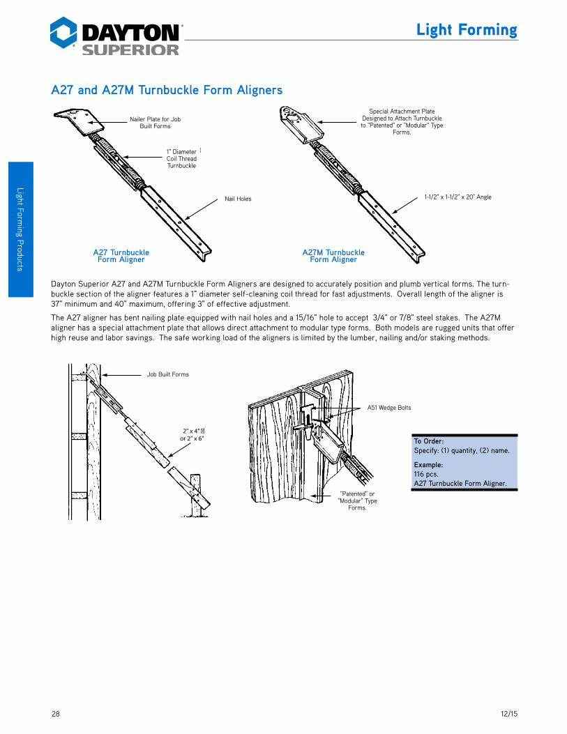
28 12/15
Light Forming P
roducts
Light Forming
A27 and A27M Turnbuckle Form Aligners
Dayton Superior A27 and A27M Turnbuckle Form Aligners are designed to accurately position and plumb vertical forms. The turn-buckle section of the aligner features a 1" diameter self-cleaning coil thread for fast adjustments. Overall length of the aligner is 37" minimum and 40" maximum, offering 3" of effective adjustment.
The A27 aligner has bent nailing plate equipped with nail holes and a 15/16" hole to accept 3/4" or 7/8" steel stakes. The A27M aligner has a special attachment plate that allows direct attachment to modular type forms. Both models are rugged units that offer high reuse and labor savings. The safe working load of the aligners is limited by the lumber, nailing and/or staking methods.
Nailer Plate for�Job Built Forms
1" Diameter�Coil Thread�Turnbuckle
Nail Holes
Special Attachment Plate�Designed to Attach Turnbuckle�to “Patented” or “Modular”�Type Forms.
1-1/2" x 1-1/2" x 20˚ Angle
A27 Turnbuckle Form Aligner
A27M Turnbuckle Form Aligner
Job Built Forms
2" x 4" �or 2" x 6"
A-51 Wedge Bolts
“Patented” or �“Modular” Form
To Order:Specify: (1) quantity, (2) name.
Example:116 pcs. A27 Turnbuckle Form Aligner.
Nail Holes 1-1/2" x 1-1/2" x 20° Angle
1" Diameter Coil Thread Turnbuckle
Special Attachment Plate Designed to Attach Turnbuckle to "Patented" or "Modular" Type
Forms.
"Patented" or "Modular" Type
Forms.
Nailer Plate for Job Built Forms
Job Built Forms
A51 Wedge Bolts

2912/15
Ligh
t For
min
g P
rodu
cts
Light Forming
A29 Snap Tie WrenchDayton Superior A29 Snap Tie Wrench is designed to facilitate snap
tie breakback.
Using the A29 Snap Tie Wrench:1. After the form has been removed slide the wrench up the tie until the front of the wrench
contacts the concrete.
2. Keep the wrench tight against the concrete and push the handle towards the concrete, thus bending the tie nearly 90˚. Next, rotate the wrench around the centerline of the tie. 1/4 to 1/2 turn is usually sufficient to snap off the tie end.
A31 Wrench Head Snap Tie SocketA31 is designed to facilitate A4-H Hex Head Snap Tie breakback.
A40 Cone Removal WrenchDayton Superior A40 Cone Removal Wrench is designed to facilitate plastic cone removal.
A43 Footing TieThe A43 Footing Tie is used to form footers or grade beams up to 42" wide. Footing Ties provide an economical way to support concrete forms from bowing or collapsing while con-crete is being poured. The Safe Working Load is limited to lumber and/or nailing.
A46 Stayform TieA46 Stayform Ties are manufactured with a standard loop on one end and nut and keeper on another end. For use with A110 Metal Rib.
A46B1 Combination TieA46B1 Combination Ties are manufactured with a standard loop on one end and 1/2" coil tie on another. They are used for connecting Steel-Ply forms to coil rod for blind-side wall application.
A46B1 (Special) Combination TieA46B1 (Special) Combination Ties are manufactured with a standard loop on one end and 1/2" coil tie on another. They are used for connecting Steel-Ply forms to coil rod for blind-side wall application.
A29 Snap Tie Wrench
A31 Wrench Head Snap Tie Socket
A43 Footing Tie

30 12/15
Light Forming P
roducts
Light Forming
A44 Stainless Steel Snap Tie
Dayton Superior A44 Stainless Steel Snap Ties are available for applications that require ties resistant to rusting or other similar corrosion. The A44 tie is available with button style head. Hex head or penta head not available. It has either 15/16" diameter metal spreader washers or standard plastic cones. The tie holes left after breakback may be left open and ungrouted to give an archi-tectural design in the concrete.Note: Due to the ductility of the type 304 stainless steel wire, Dayton Superior can not guarantee that these ties will consistently provide proper breakback. SWL provides a factor of safety of ap-proximately 2 to 1.
A45 Base TieDayton Superior A45 Base Ties are used at the base and/or top of modular type formwork. Standard base ties are furnished without cones or breakback.
A46 Loop Panel Tie, Standard and HeavyDayton Superior A46 Loop Panel Ties are designed for securing and spacing modular type forms. Standard units are fabricated with 2-1/8" ends and 1" breakback. Other breakbacks are available on special order.
A46 Loop Panel Ties are available with plastic cones and water-resis-tant washer. The water-resistant washer is designed to help eliminate water seeping along the tie by breaking the surface continuity of the wire.
When erecting modular type forms, the A46 ties are placed in the slots between the form panels. An A51 Wedge Bolt is placed through the adjoining form and into the loop of each tie. A second Wedge Bolt is then placed through the slot of the first Wedge Bolt to secure the tie and form together.
A46 Stainless Steel Loop Ties are available for applications that require ties resistant to rusting or other similar corrosion. A46 Stainless Steel Loop Ties are available with plastic cone and water resistant washer.Note: Due to the ductility of the type 304 stainless steel wire, Dayton Superior can not guarantee that these ties will consistently provide proper breakback. SWL provides a factor of safety of approximately 2 to 1.
Shown with 1" x 1"�Plastic Cones
A44 Stainless Steel Snap Tie
To Order A25:Specify: (1) quantity, (2) name, (3) wall thickness (4) lumber and wedge dimension (allow 1/2" for wedge take up) (5) cone size or with washers (break back).
Example:2,500 pcs. A44 Stainless Steel Snap Ties, 12" wall, 8-1/4" L&W, 1"x1" Plastic Cone.
2,150 lbs.Safe Working Load
Wall Thickness 1-5/32"1-5/32"
A45 Base Tie
To Order:Specify: (1) quantity, (2) name, (3) wall dimension.Example:500 pcs. A45 Base Tie for 8" Wall.
To Order:Specify: (1) quantity, (2) name, (3) standard or heavy, (4) wall thickness, (5) special features desired.
Example:5,000 pcs., A46 Loop Panel Tie, Standard for 12" wall with 1"x1" Plastic Cones.
2,250 lbs. for Standard Ties2,500 lbs. for Stainless Steel Ties
3,000 lbs. for Heavy TiesSafe Working Loads
SWL provides a factor of safety of approximately 2 to 1.
Shown with 1" x 1" Plastic Cones
Wall Thickness
A-46 Loop Panel Tie
A-51 Wedge Bolts
Modular Type Form
A51 Wedge Bolts
A46 Loop Panel Tie
Modular Type Forms
A46 Loop Panel Tie
2-1/8"Wall Thickness
Breakback
Anti-Turn Feature: (Crimp or Flat)
Rev. 10/17

3112/15
Ligh
t For
min
g P
rodu
cts
Light Forming
A48 Gang Loop Tie, Standard and Heavy
Dayton Superior A48 Gang Loop Tie is similar to the A46 tie, but has end dimensions extended to 4-15/16". The longer length allows the tie to be used with gang form bolts (supplied by others) and to be broken back before the form has been stripped. 1" breakback is standard. Other breakbacks, plastic cones and/or water resistant washers are available on special order.
A51 Wedge BoltDayton Superior A51 Wedge Bolt is used with A46 Loop Panel Ties, B21 Plylags, etc., to secure modular type forms.
A52 Z Tie Holder and A53 Waler TieDayton Superior A52 Z Tie Holder is used in conjunction with the A53 Waler Tie to secure double 2x lumber wales to modular type forms. The A53 Waler Tie is available in two sizes to accommodate 2 x 4 and 2 x 6 lumber.
Modular Type Form
Gang Form BoltBy Others
A48 GangLoop Tie
A51 W edge Bolts
4-15/16"Wall Thickness
Break Back
Anti-turn Feature:�(Crimp or Flat)
A48 Gang Loop Tie
2,250 lbs. for Standard Ties3,000 lbs. for Heavy Ties
Safe Working Loads
To Order:Specify: (1) quantity, (2) name, (3) standard or heavy, (4) wall thickness, (5) special features desired.
Example:5,000 pcs. A48 Gang Loop Tie, Standard for 12" wall with 1"x1" Plastic Cones.
SWL provides a factor of safety of approximately 2 to 1.
3,750 lbs.Safe Working Load
A51 Wedge Bolt
To Order A25:Specify: (1) quantity, (2) name.
Example:5,000 pcs. A51 Wedge Bolt.
SWL provides a factor of safety of approximately 2 to 1.
A52 Z Tie Holder
A53 W aler Tie
A52 Z Tie Holder
A53 Waler Tie
To Order A52 Z: Example:Specify: (1) quantity, 500 pcs. A52 Z Tie Holder. (2) name.
To Order A53: Example:Specify: (1) quantity, 500 pcs. A53 Waler Tie,(2) name, (3) length. 6-3/16" long.
Wall Thickness
A51 Wedge Bolts
A53 Waler Tie
A52 Z Tie Holder
A48 Gang Loop Tie
Gang Form Bolt by Others
Modular Type Forms
Breakback
Anti-Turn Feature: (Crimp or Flat)
A53 Selection ChartTie Type Overall Length Designed to Fit
A53 6-3/16" Double 2x4 Wales
A53 8-1/32" Double 2x6 Wales
For attaching strongbacks see A63 Strongback Tie

32 12/15
Light Forming P
roducts
Light Forming
A54 Snaplug® Dayton Superior Snaplugs patch plastic cone tie holes. The Snaplug is easily installed using Snaplug® Bonder. The plug is designed to fit the hole of a 1" x 1" plastic cone and comes in a concrete gray color. Other colors are available on special order. Two styles are available: Flush (PC 304121) and 1/4" Reveal/Setback (PC 304122).
A55 Sure-Lock Tie, A56 Sure-Lock Bracket, A57 Sure-Lock Strongback BracketDayton Superior Sure-Lock Forming System consists of the A55 Sure-Lock Tie, A56 Sure-Lock Bracket and the A57 Sure-Lock Strongback Bracket. This system is an economical single waler forming method based on 2 x 4 lumber and 3/4" plywood. A series of 7/8" diameter holes are required in plywood for A55 loop to pass through.
The A55 Sure-Lock Tie is manufactured with self-centering 1" x 1" plastic cones that provide a nominal 1" breakback. Other break-backs and water resistant washers are available for the A55 tie on special order.
The A56 Sure-Lock Bracket is a sturdy bracket designed with a rotating arm that captures the loop of the A55 tie and firmly secures the tie and waler to the form.
The A57 Sure-Lock Strongback Bracket attaches to the back of the A56 bracket and holds a 2x4 strongback firmly to the form.
To Order :Specify: (1) quantity, (2) name.
Example:5,000 pcs. A54 Snaplugs.
Snaplug
24'
24'
24'
To Order A55 Sure-Lock Tie:Specify: (1) quantity, (2) name, (3) wall thickness,(4) special features desired.
To Order A56 Sure-Lock Bracket:Specify: (1) quantity, (2) name
To Order A57 Sure-Lock Strong Back Clamp:Specify: (1) quantity, (2) name.
Example:5,000 pcs. A55 Sure-Lock Ties, 10" wall with waterseal washers.
Example:500 pcs. A56 Sure-Lock Brackets.
Example:200 pcs. A57 Sure-Lock Strong Back Clamps.
2,250 lbs.Safe Working Load
SWL provides a factor of safety of approxi-mately 2 to 1.
A55 Sure-Lock Tie
A56 Sure-Lock Bracket
A57 Sure-Lock Strong Back
Clamp
Empty Cone Hole
1"
1"
5/8"
1/4" Setback

3312/15
Ligh
t For
min
g P
rodu
cts
Light Forming
A63 Strongback Loop TieDayton Superior A63 Strongback Loop Tie is a long-ended loop tie used in conjunction with the A52 Z Tie Holder to securely attach wales and strongbacks to modular forms. A63 ties are available in three sizes to fit various lumber combinations. See chart below.
A81 Jahn® “A” BracketDayton Superior A81 Jahn “A” Bracket is fabricated from high strength steel with a cad plated eccentric and painted body. The 5/8" take-up of the eccentric compensates for minor lumber variations in thickness. The A81 bracket can be utilized to hold a single horizontal wale or a single vertical stud with any type of wall form; round, curved, battered, beam and/or columns
The A81 bracket can be installed before or after the wales have been positioned. The slots in the bracket allow it to slip over the snap tie end without laborious threading through holes. When properly installed, the A81 bracket will not loosen from internal
vibration of the concrete. Pressure from the bracket is against the 2 x 4 instead of the plywood.
The A81 bracket uses 4-3/4" L&W snap ties, is easy to install and strip, requires no nailing and is very fast. See preparation steps after A89 for bracket spacing and concrete placement rates.
A-51 Wedge Bolts
A-63 �Strongback �Tie
A63 Strongback Loop Tie
To Order:Specify: (1) quantity, (2) name.
Example:2,000 pcs. A81 Jahn “A” Bracket.
A81 Jahn “A” Bracket
To Order:Specify: (1) quantity, (2) name, (3) length.
Example:500 pcs. A63 Strongback Loop Tie, 9-3/4" long.
A63 Strongback Loop Tie Selection ChartTie Type Overall Length Designed to Fit
A63 9-3/4" 2x4 Wales and Double 2x4 Strongbacks
A63 11-5/8" 2x4 Wales and Double 2x6 Strongbacks
A63 13-1/2" 2x6 Wales and Double 2x6 Strongbacks
A51 Wedge Bolts
A63 Strongback Tie

34 12/15
Light Forming P
roducts
Light Forming
A82 Jahn® “C” BracketDayton Superior A82 Jahn “C” Bracket is designed for use with single 2 x 4 studs, double 2 x 4 wales and 8-1/4" L&W snap ties to attach vertical strongbacks to the form. The bracket eccentric compensates for lumber size imperfections. The A82 bracket can also be used with double wales to support a horizontal plywood joint. See preparation steps after A89 for bracket spacing and con-crete placement rates.
A83 Jahn® CornerlockDayton Superior A83 Jahn Cornerlock is used at outside corners to secure the 2 x 4 walers. Nail holes are provided for secure attachment and grips on the underside provide a positive non-slip action. The cam action of the locking handle draws the wales together. No special tools are required for installation or stripping.
To Order:Specify: (1) quantity, (2) name.
Example:4,950 pcs. A82 Jahn “C” Bracket.
A82 Jahn “C” Bracket
To Order:Specify: (1) quantity, (2) name.
Example:100 pcs. A83 Jahn Cornerlock.
A83 Jahn Cornerlock

3512/15
Ligh
t For
min
g P
rodu
cts
Light Forming
A89 Jahn® Scaffold JackDayton Superior A89 Jahn Scaffold Jack is an all steel unit designed to fit 24" x 24" and 16" x 24" tie and wale spacing. This jack is equipped with a built-in guard rail receptacle and is designed to hold two 2 x 10 planks for a comfortable work platform.
The scaffold jack attaches to two “A” brackets with the horizontal rod and is equipped with nailing holes top and bottom to secure it in place. Maximum spacing for the A89 jack is 8'-0".
The horizontal rod slides easily through the body of the “A” bracket for support, with the long end being installed first. Nail holes are provided for securing the jack to both the top and bottom support walers.
Warning: A89 Jahn Scaffold Bracket is designed to support 25 psf walkway loads only, after both sides of the formwork have been installed. Heavy loads placed on a scaffold jack may cause metal snap tie washers to bend or plastic snap tie cones to crush result-ing in incorrect wall thickness.
To Order:Specify: (1) quantity, (2) name.
Example:50 pcs. A89 Jahn Scaffold Jack.
Jack Adjusted for 16" Spacing of Wales
Jack Adjusted for 24" Spacing of Wales

36 12/15
Light Forming P
roducts
Light Forming
How to Use the Jahn® Forming System1. PreparationGang drilling the plywood is the only preparation required. Holes need to be drilled 1/8" larger than the snap tie head. Normally, a 5/8" diameter drill bit will be required.
The 5/8" take-up of the eccentric on the Jahn “A” Bracket allows a snap tie with a L&W dimension of 4-3/4" to be used with 5/8" or 3/4" plywood. The 5/8" take-up on the “C” bracket allows it and 8-1/4" snap ties to be used on 5/8" and 3/4" plywood.
2. Snap Tie Spacing and Rate of PlacementThe most common snap tie spacings being used with the Jahn Forming System are shown below. For different rates of pour and/or other tie spacing, contact a Dayton Superior Technical Services Department. Refer to the web site for addresses and phone numbers.
12" vertical x 24" horizontal 16" vertical x 24" horizontal 12" vertical x 12" horizontal Snap Tie Spacing. Snap Tie spacing. Snap Tie spacing. Recommended rate of Recommended rate of Recommended rate of placement 4.5 ft./hr. at 70°. placement 2.0 ft./hr. at 70°. placement 4.5 ft./hr. at 70°.
Plywood Used Strong Way (Face Grain Parallel to Spacing)
Notes: The above recommendations are based on the use of 3/4" Plyform Class I, and 2x4 S4S studs (Douglas Fir-Larch, Southern Pine or equal having a minimum allowable fibre stress of 1,200 psi).Design is based on all formwork members being continuous over four or more supports.For multi-lift forming, see 12 Joint Cover Details.
Gang Drilling�of Plywood
6"
6"
12"
12"
12"
12"
12"
12"
12"
12"24"
4'-0"
8'-0"
12"
8"
16"
16"
16"
16"
8"
16"
12"24"
4'-0"
8'-0"
12"
12"
12"
12"
12"
12"
12"
12"
12"
12"12"12"
4'-0"
8'-0"
12"
Gang Drilling of Plywood
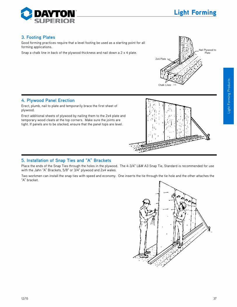
3712/15
Ligh
t For
min
g P
rodu
cts
Light Forming
3. Footing PlatesGood forming practices require that a level footing be used as a starting point for all forming applications.
Snap a chalk line in back of the plywood thickness and nail down a 2 x 4 plate.
4. Plywood Panel ErectionErect, plumb, nail to plate and temporarily brace the first sheet of plywood.
Erect additional sheets of plywood by nailing them to the 2x4 plate and temporary wood cleats at the top corners. Make sure the joints are tight. If panels are to be stacked, ensure that the panel tops are level.
5. Installation of Snap Ties and “A” BracketsPlace the ends of the Snap Ties through the holes in the plywood. The 4-3/4" L&W A3 Snap Tie, Standard is recommended for use with the Jahn “A” Brackets, 5/8" or 3/4" plywood and 2x4 wales.
Two workmen can install the snap ties with speed and economy. One inserts the tie through the tie hole and the other attaches the “A” bracket.
2x4 Plate
Chalk Lines
Nail PlywoTo Plate
2x4 Plate
Nail Plywood to Plate
Chalk Lines

38 12/15
Light Forming P
roducts
Light Forming
Proper “A” Bracket Installation
Without Waler In Place:
With Waler In Place:
6. Installation of WalesInstall the walers into the brackets working from top to bottom of the panel and tightening the eccentric as you go. Waler joints should occur at a bracket or a scab should be utilized to reinforce the joint (see sketch).
7. Inside Wall Panel ErectionThe inside panel sequence is the same as the outside panel described above except for the placement of the plywood panels over the tie ends. This can be accomplished by two workmen by starting at the bottom and moving the panel from side to side and up and down to align the snap ties with the holes in the plywood.
5A. Place The “A” bracket on the tie end by slipping the tie end into the slots in the bracket body.
5B. Rotate the eccentric loosely over the tie end.
5C. Drop 2x4 waler in place. Seat 2x4 with hammer, if necessary.
5D. Slip the back slot in the bracket body over the tie directly behind the head.
5F. Push the bracket toward the plywood until the tie head emerges through the front of the bracket.
5G. Rotate the eccentric over the tie head and tighten.
Placing Waler
Tightening Waler
Scabbed Joint and�“C” Brackets
Wale Joint �at “A” BracketWale Joint at “A” Brackets
Scabbed Joint and “C” Brackets

3912/15
Ligh
t For
min
g P
rodu
cts
Light Forming
8. Inside Corner FormingNo special treatment is required for inside corners other than the alternating of the wales as shown in the sketch. It is advantageous to start the inside corners with full size plywood panels to facilitate forming the outside corners.
9. Outside Corner FormingInstall the first outside panel in line with the first inside panel. Filler panels, the same thickness as the wall plus the plywood thickness, are then used to fill out the exterior corner.
10. Installation of A83 Jahn CornerlockThe A83 cornerlock eliminates costly overlapping and blocking of the wales. Its cam action draws the wales securely together. Place one wale flush at the corner and let the other extend past the flush one. Slip the cornerlock into place with the handle perpendicular to the wale. Nail the cornerlock in place and rotate the handle 90˚ toward the wale. A snug, tight outside corner is accomplished.
11. Installation of StrongbacksStrongbacks are used to aid in form alignment and to tie stacked panels together. Loose 2x4’s are used in conjunc-tion with A82 Jahn “C” Brackets and 8-1/4" L&W snap ties or 4-3/4" L&W snap ties with the A86 Jahn Tie Extenders to strongback the forms. Normal strongback spacing is 8'-0" on center.
Handle
4'-0"Filler Panels
8'-0"�Typical
Filler Panels
Handle
8'-0" Typical
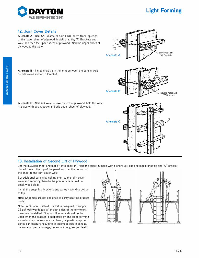
40 12/15
Light Forming P
roducts
Light Forming
12. Joint Cover DetailsAlternate A - Drill 5/8" diameter hole 1-1/8" down from top edge of the lower sheet of plywood. Install snap tie, “A” Brackets and wale and then the upper sheet of plywood. Nail the upper sheet of plywood to the wale.
Alternate B - Install snap tie in the joint between the panels. Add double wales and a “C” Bracket.
Alternate C - Nail 4x4 wale to lower sheet of plywood, hold the wale in place with strongbacks and add upper sheet of plywood.
13. Installation of Second Lift of PlywoodLift the plywood sheet and place it into position. Hold the sheet in place with a short 2x4 spacing block, snap tie and “C” Bracket placed toward the top of the panel and nail the bottom of the sheet to the joint cover wale.
Set additional panels by nailing them to the joint cover wale and securing them to the previous panel with a small wood cleat.
Install the snap ties, brackets and wales - working bottom to top.
Note: Snap ties are not designed to carry scaffold bracket loads.
Note: A89 Jahn Scaffold Bracket is designed to support 25 psf walkway loads, after both sides of the formwork have been installed. Scaffold Brackets should not be used when the bracket is supported by one sided forming, as metal snap tie washers can bend, or plastic snap tie cones can fracture resulting in incorrect wall thickness, personal property damage, personal injury, and/or death.
Single Wale and�“A” Brackets
1-1/8"
Alternate A
Double Wales and�“C” Brackets
Alternate B
4x4Alternate C
Single Wale and “A” Brackets
Double Wales and “C” Brackets

4112/15
Ligh
t For
min
g P
rodu
cts
Light Forming
14. Haunch or Corbel Forming A low wall with a light corbel or For heavy corbels or haunches haunch can be formed using forming use vertical strongbacks, the method illustrated below. T shores and “A” and “C” Brackets.
15. Step FormingUse of Jahn “C” Brackets and Jahn Tie Extenders to attach strongbacks allows 2x4 wales to run free and holes do not have to line up at stepdowns.
When tie alignment is fairly close, “C” Brackets can be used as shown in the sketch.
Filler
Banding �Optional
Filler as�Required
“A” Brackets1" x 4" Scab
“C” Brackets
Filler
“T” Shore
Strongbacks
“A” Brackets
Strongback
“A” Brackets
“C” Brackets
Stepdown Footer
“A” Brackets
Stepdown Footer
“A” Brackets
Filler
1"x4" Scab
Strongbacks
Strongback
Banding Optional
Filler as Required
Filler
“A” Brackets“T” Shore
“C” Brackets
“C” Brackets

42 12/15
Light Forming P
roducts
Light Forming
16. Brick Ledge FormingBrick ledges can be quickly formed with 2x4s placed either verti-cally or horizontally. By adding shims of required thickness to a 2x4, ledges of varying thickness can be formed.
17. 3-Way Wall Forming3-way walls can be formed using “A” and “C” Brackets with single and double wales, as shown in the sketches.
Variable
LedgeBrick
“A” Brackets
“C” Brackets
Strongbacks at 8'-0" craters“C” Brackets
“A” Brackets
Double Wales
All “A” Brackets All “A” Brackets
“A” Brackets
Variable
LedgeBrick
“A” Brackets
All “A” Brackets
Double Wales
Stongbacks at 8'-0" Centers
All “A” Brackets
“C” Brackets
“C” Brackets
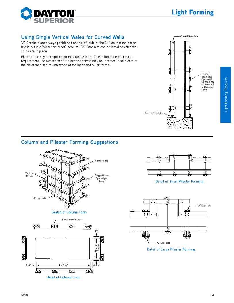
4312/15
Ligh
t For
min
g P
rodu
cts
Light Forming
Using Single Vertical Wales for Curved Walls“A” Brackets are always positioned on the left side of the 2x4 so that the eccen-tric is set in a “vibration-proof” posture. “A” Brackets can be installed after the studs are in place.
Filler strips may be required on the outside face. To eliminate the filler strip requirement, the two sides of the interior panels may be trimmed to take care of the difference in circumference of the inner and outer forms.
Column and Pilaster Forming Suggestions
Curved Template
1"x4"�Banding�Optional�Depending�on Amount�of Bracing�Used.
Curved Template
Cornerlocks
Single Wales�Spaced per�Design
Vertical �Studs
“A” Brackets
Sketch of Column Form
Detail of Small Pilaster Forming
Detail of Large Pilaster Forming
“A” Brackets
“C” Brackets
Studs per Design
L + 3/4"
W �+ �
3/4"
3/4"
3/4"3/4"
Detail of Column Form
“A” Brackets
“A” Brackets
Cornerlocks
Single Wales Spaced per
Design
Vertical Studs
“C” Brackets

44 12/15
Light Forming P
roducts
Light Forming
A90 Scaffold Bracket Jack
Dayton Superior A90 Scaffold Bracket Jack meets state building codes and OSHA minimum requirements and supports scaffold-ing on nearly any type of formwork. By changing the position of the pins in the vertical and horizontal members the bracket can be quickly adjusted to fit 2x4, 2x6 or 2x8 wales or positioned flush against a wall.
Attachment can be made to a concrete wall by attaching the bracket to an exposed coil tie, insert or other appropriate device. The bracket has a 1" diameter pipe coupling welded to the vertical leg which can be used in conjunction with a six inch long pipe nipple to attach the bracket to an exposed she-bolt inside rod.
The A90 Scaffold Bracket Jack folds for easy storage and convenient shipping.
Replacement parts for the A90 bracket are available on special order. Contact a Dayton Superior Service Center for cost and avail-ability.
Built-in Receptaclefor 2"x4" Handrail Post
8'-0"Maximum Centers
A90 Scaffold Jack
32"
40"
To Order:Specify: (1) quantity, (2) name.
Example:250 pcs. A90 Scaffold Bracket Jack.
8'-0" Maximum Centers
A90 Scaffold Jack
Built-in Receptacle for 2x4 Handrail
Post
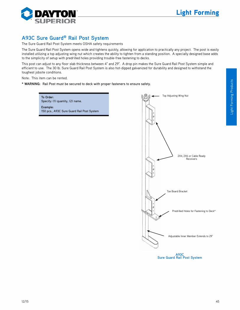
4512/15
Ligh
t For
min
g P
rodu
cts
Light Forming
A93C Sure Guard® Rail Post SystemThe Sure Guard Rail Post System meets OSHA safety requirements
The Sure Guard Rail Post System opens wide and tightens quickly, allowing for application to practically any project. The post is easily installed utilizing a top adjusting wing nut which creates the ability to tighten from a standing position. A specially designed base adds to the simplicity of setup with predrilled holes providing trouble-free fastening to decks.
This post can adjust to any floor slab thickness between 4" and 29". A drop pin makes the Sure Guard Rail Post System simple and efficient to use. The 30 lb. Sure Guard Rail Post System is also hot-dipped galvanized for durability and designed to withstand the toughest jobsite conditions.
Note: This item can be rented.
* WARNING: Rail Post must be secured to deck with proper fasteners to ensure safety.
To Order:Specify: (1) quantity, (2) name.
Example:150 pcs., A93C Sure Guard Rail Post System
A93CSure Guard Rail Post System
Top Adjusting Wing Nut
2X4, 2X6 or Cable Ready Receivers
Toe Board Bracket
Predrilled Holes for Fastening to Deck*
Adjustable Inner Member Extends to 29"

46 12/15
Light Forming P
roducts
Light Forming
A100 Speed Step® BracketDayton Superior Speed Step Bracket (A100) is a reusable, high grade composite resin forming bracket designed to simplify layout, set-up and stripping of concrete stair forming. The brackets are nailed to 2 x 4 stringers and adjusted for a 4" to 8" riser and 10" to 20" tread. One size fits all standard stairs.
Step 1 S P E E D S T E P
Step 2
To Order:Specify: (1) quantity, (2) name.
Example:150, A100 Speed Step Brackets
Straight Riser Battered Riser
Step 3
6D Duplex Nail Holes
Indicator Marks
Pivot Point Nail Hole
Knee Board LedgeNosing Corner
Legend
A110 Dayton Superior Metal RibDayton Superior Metal Rib is the formwork solution for tough forming situations. It can be cut in the field with tin snips, and be bent to form curves. Dayton Superior Metal Rib is versatile enough for any type or size structure.
Features:• Lightweight sheets are easily cut and installed in the field,
reducing labor costs
• Formwork is left in place, so no stripping of forms required —simply remove bracing
• Easily locate any penetrations in formwork
• Enables the pour to be visually monitored
• No need to clean, reface or oil formwork
• Can be used in applications ranging from pile caps and foot-ings, to blind side walls and tunnels
• Concrete pours in 3 to 4 foot lifts are preferable with this forming system
• Can be used with Symons Steel-Ply (A46 Stayform) or job-built forms (A3 Stayform Tie)
Metal Rib PropertiesProduct Code 139700
Sheet Size 27" x 97"Surface/sheet 18 sq.ftPallet/Ordering 250 sheets/4500 sq.ft
Rib Space 3.80"Sheet Thickness 26 GaWeight per piece 11.90 lb
FIRST: Attach Stringer and Brackets to Check Wall
FIRST: Snap Chalk Line on Center of 2x4
FIRST: Align and Mark Pivot Points at Mark on Chalk Line
Hold Square Tight to Underside of Knee
Board Edge
NOTE: Chalk Line Should Line Up with
Same Indicator Marks on All Brackets.
ADDITIONAL BRACKETS: DO NOT Use Framing Square. Simply Nail Pivot Point on Chalk Line Marks. They
Count Indicator Marks and Nail. Layout is the Same for All Brackets.
THIRD: Rotate Brackets Simultaneously Holding
Square Tight on Run Length on First Bracket Nosing Corner until Rise
Height is Aligned on Second Bracket Nosing
Corner.
SECOND: Nail on Riser Form
Finishing Knee Board
6d Spacer Nail
2x4 Stringer
Equal
Rise
Rise
Run
Run
Equal EqualSECOND: Use
Framing Square to Mark Rise and Run
on Chalk Line
SECOND: Align Run Length at Bracket Nosing Corner
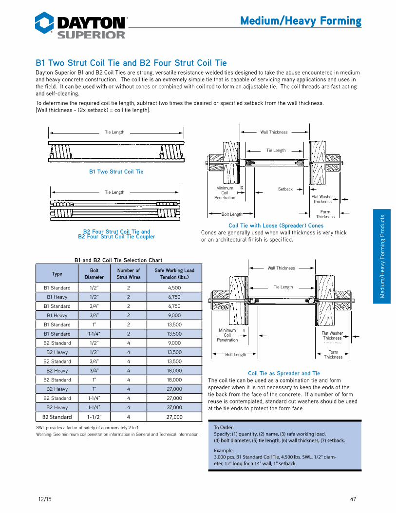
4712/15
Med
ium
/Hea
vy F
orm
ing
Pro
duct
s
Medium/Heavy Forming
B1 Two Strut Coil Tie and B2 Four Strut Coil TieDayton Superior B1 and B2 Coil Ties are strong, versatile resistance welded ties designed to take the abuse encountered in medium and heavy concrete construction. The coil tie is an extremely simple tie that is capable of servicing many applications and uses in the field. It can be used with or without cones or combined with coil rod to form an adjustable tie. The coil threads are fast acting and self-cleaning.
To determine the required coil tie length, subtract two times the desired or specified setback from the wall thickness. [Wall thickness - (2x setback) = coil tie length].
B1 Two Strut Coil Tie
Tie Length
B2 Four Strut Coil Tie andB2 Four Strut Coil Tie Coupler
Tie Length
Bolt �Length
Tie Length
Wall Thickness
Minimum�Coil �
Penetration
Form �Thickness
SetbackFlat �
Washer �Thickness
To Order:Specify: (1) quantity, (2) name, (3) safe working load, (4) bolt diameter, (5) tie length, (6) wall thickness, (7) setback.
Example:3,000 pcs. B1 Standard Coil Tie, 4,500 lbs. SWL, 1/2" diam-eter, 12" long for a 14" wall, 1" setback.
SWL provides a factor of safety of approximately 2 to 1.Warning: See minimum coil penetration information in General and Technical Information.
B1 and B2 Coil Tie Selection Chart
TypeBolt
DiameterNumber of Strut Wires
Safe Working Load Tension (lbs.)
B1 Standard 1/2" 2 4,500
B1 Heavy 1/2" 2 6,750
B1 Standard 3/4" 2 6,750
B1 Heavy 3/4" 2 9,000
B1 Standard 1" 2 13,500
B1 Standard 1-1/4" 2 13,500
B2 Standard 1/2" 4 9,000
B2 Heavy 1/2" 4 13,500
B2 Standard 3/4" 4 13,500
B2 Heavy 3/4" 4 18,000
B2 Standard 1" 4 18,000
B2 Heavy 1" 4 27,000
B2 Standard 1-1/4" 4 27,000
B2 Heavy 1-1/4" 4 37,000
B2 Standard 1-1/2" 4 27,000
Coil Tie with Loose (Spreader) ConesCones are generally used when wall thickness is very thick or an architectural finish is specified.
Bolt �Length
Tie Length
Wall Thickness
Minimum�Coil �
Penetration
Form �Thickness
Flat �Washer �
Thickness
Coil Tie as Spreader and TieThe coil tie can be used as a combination tie and form spreader when it is not necessary to keep the ends of the tie back from the face of the concrete. If a number of form reuse is contemplated, standard cut washers should be used at the tie ends to protect the form face.
Tie Length
Tie Length
Tie Length
Setback
Bolt Length Form Thickness
Flat Washer Thickness
Minimum Coil
Penetration
Wall Thickness
Tie Length
Bolt Length Form Thickness
Flat Washer Thickness
Minimum Coil
Penetration
Wall Thickness
Medium/Heavy Forming

48 12/15
Medium
/Heavy Form
ing Products
Medium/Heavy Forming
B1B3 and B2B3 Screw-On Coil TieDayton Superior Screw-On Coil Tie is designed with longer coils that extend beyond the end of the struts. Plastic cones screw onto the projections to provide a positive setback and act as a fixed internal form spreader.
To determine proper screw-on coil tie length, subtract the required total setback (both sides) from the wall thickness.
Tie LengthSetback
B30 Screw-On Plastic Cone
Setback
B1B3 Screw-On Coil Tie
7/16" for 1/2" and 3/4" Dia. Coils1/2" for 1" and 1-1/4" Dia. Coils
W all Thickness
Bolt �Length
Tie Length SetbackSetback
Wall Thickness
Minimum�Coil �
Penetration
Form �Thickness
Cone�Length
Flat �Washer �
Thickness
Form Panel Showing B3 Coil Ties in PlPrior to Installation ofReinforcing Steeland Closure Form .
To Order:Specify: (1) quantity, (2) name, (3) safe working load, (4) bolt diameter, (5) tie length, (6) wall thickness, (7) setback.
Example:1,500 pcs. B1B3 Screw-On Coil Tie, 6,750 lbs. SWL, 1/2" diameter, 22 long for a 24" wall, 1" setback.
B1B3 and B2B3 Screw-On Coil Tie Selection Chart
Type Bolt Diameter
Number of Strut Wires
Safe Working Load Tension (lbs.)
B1B3 Standard 1/2" 2 4,500
B1B3 Heavy 1/2" 2 6,750
B1B3 Extra Heavy 1/2" 2 9,000
B1B3 Standard 3/4" 2 6,750
B1B3 Heavy 3/4" 2 9,000
B1B3 Standard 1" 2 13,500
B2B3 Standard 1/2" 4 9,000
B2B3 Standard 3/4" 4 13,500
B2B3 Heavy 3/4" 4 18,000
B2B3 Standard 1" 4 18,000
B2B3 Heavy 1" 4 27,000
B2B3 Heavy 1-1/4" 4 27,000
B2B3 36K 1-1/4" 4 37,000
SWL provides a factor of safety of approximately 2 to 1.Warning: See minimum coil penetration information in General and Technical Information.
Tie Length
Tie Length
SetbackSetback
SetbackSetback
Bolt Length
Cone Length
Form Thickness
B30 Screw-On Plastic Cone
7/16" for 1/2" and 3/4" Dia. Coils1/2" for 1" and 1-1/4" Dia. Coils
B1B3 Screw-On Coil Tie
Flat Washer
Thickness
Form panel showing B3 Coil Ties in place prior to installation of reinforcing steel and
closure form.
Minimum Coil
Penetration
Wall Thickness
Wall Thickness
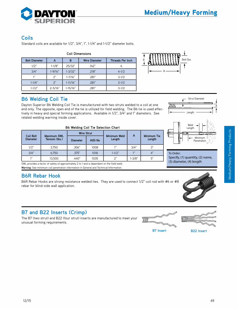
4912/15
Med
ium
/Hea
vy F
orm
ing
Pro
duct
s
Medium/Heavy Forming
CoilsStandard coils are available for 1/2", 3/4", 1", 1-1/4" and 1-1/2" diameter bolts.
Coil Dimensions
Bolt Diameter A B Wire Diameter Threads Per Inch
1/2" 1-1/8" 25/32" .162" 6
3/4" 1-9/16" 1-3/32" .218" 4-1/2
1" 2" 1-7/16" .281" 3-1/2
1-1/4" 2" 1-11/16" .281" 3-1/2
1-1/2" 2-5/16" 1-15/16" .281" 3-1/2
B6 Welding Coil TieDayton Superior B6 Welding Coil Tie is manufactured with two struts welded to a coil at one end only. The opposite, open end of the tie is utilized for field welding. The B6 tie is used effec-tively in heavy and special forming applications. Available in 1/2", 3/4" and 1" diameters. See related welding warning inside cover.
B6 Welding Coil Tie Selection Chart
Coil Bolt Diameter
Maximum SWL Tension (lbs.)
Wire StrutMinimum Weld
LengthA
Minimum Tie LengthDiameter AISI No
1/2" 3,750 .306" 1008 1" 3/4" 3"
3/4" 6,750 .375" 1018 1-1/2" 1" 4"
1" 13,500 .440" 1035 2" 1-3/8" 5"
SWL provides a factor of safety of approximately 2 to 1 and is dependent on the field weld.Warning: See minimum coil penetration information in General and Technical Information.
B6R Rebar HookB6R Rebar Hooks are strong resistance welded ties. They are used to connect 1/2" coil rod with #6 or #8 rebar for blind-side wall application.
B7 and B22 Inserts (Crimp)The B7 (two strut) and B22 (four strut) inserts are manufactured to meet your unusual forming requirements.
To Order:Specify, (1) quantity, (2) name, (3) diameter, (4) length
A
B Bolt�Dia.
Length
A
Strut Diameter
Minimum�Coil Penetration
Weld�Length
B22 InsertB7 Insert
Bolt Dia.
Strut Diameter
B
Length
Weld Length
Minimum Penetration

50 12/15
Medium
/Heavy Form
ing Products
Medium/Heavy Forming
B11 Flat WashersDayton Superior B11 Flat Washers are made from flat steel plate and are available in the sizes shown in the accompanying chart. For best results, the space spanned by the washer should not exceed the bolt diameter plus 1/4".
B11 Flat Washer Selection Chart
Bolt Diameter Type Safe Working Load (lbs.) Size
1/2" Standard 6,750 3" x 4" x 1/4"
1/2" Heavy 8,750 4" x 5" x 1/4"
3/4" Standard 6,750 4" x 5" x 1/4"
3/4" Heavy 14,000 5" x 5" x 3/8"
1" Standard 18,500 5" x 5" x 1/2"
1" Heavy 38,000 7" x 7" x 3/4"
1-1/4" Standard 22,750 5" x 5" x 1/2"
1-1/4" Heavy 50,750 7" x 7" x 3/4"
1-1/2" Standard 26,250 5" x 5" x 3/4"
1-1/2" Heavy 41,500 7" x 7" x 3/4"
SWL provides a factor of safety of approximately 2 to 1.
B12 Coil RodDayton Superior B12 Coil Rod is available in 1/2" to 1-1/2" diameters in 12' lengths. Field cutting can be accomplished with bolt cutters or car-borundum blades.
B12 threaded rod can be used with Coil Ties in many forming com-binations to tie formwork, for adjustable ties, for concrete embed-ments and/or emergency ties.
B12 Coil Rod Selection Chart
Coil Rod Diameter
Safe Working Loads MinimumRoot Area (sq. in.)
TensileStress (psi.)
YieldStress (psi.)
MinimumCoil
Penetration
Thread per inchTension
(lbs.)Shear (lbs.)
1/2" 9,000 6,000 .1385 130,000 110,000 2" 6
5/8" 12,000 8,000 .2124 113,000 96,000 2-1/4" 5
3/4" 18,000 12,000 .3079 117,000 100,000 2-1/4" 4.5
7/8" 24,000 16,000 .4477 117,000 100,000 2-1/2" 4.5
1" 38,000 25,300 .5410 140,000 120,000 2-1/2" 3.5
1-1/8" 46,000 30,000 .7163 126,600 105,000 2-1/2" 3.5
1-1/4" 56,000 37,500 .9161 123,000 105,000 2-1/2" 3.5
1-1/2" 68,000 45,300 1.3892 98,000 85,000 3" 3.5
SWL provides a factor of safety of approximately 2 to 1.Warning: See working load info in General and Technical Information before using B12 Coil Rod.
B39Wing Nut
30 Dia.
B11 Flat Washer
To Order:Specify: (1) quantity, (2) name, (3) bolt diameter.
Example:1,200 pcs. B11 Standard, 1/2" bolt.
To Order:Specify: (1) quantity, (2) name, (3) diameter, (4) length.
Example:500 pcs. B12 Coil Rod, 1" diameter x 12'-0" long.
B12 Coil Rod
MinimumCoil Penetration
W all Thickness
Setback
B12 Coil Rod
B1 Coil Tie
Wall Thickness
Setback
B12 Coil Rod
B39 Wing Nut
B1 Coil Tie
30 Dia.
Minimum Coil Penetration

5112/15
Med
ium
/Hea
vy F
orm
ing
Pro
duct
s
Medium/Heavy Forming
B12A D/R Thread BarDayton Superior’s D/R Thread Bar is a high strength, 15mm and 20mm ductile steel with a full length, cold-rolled contour thread. The bar’s 2-1/2 threads per inch offers fast installation and stripping. D/R Thread Bar is available in 20'-0" standard lengths and can be cut to specific project requirements. Field cutting, with Carborundum blades, is easily accomplished without thread damage.
B12AD D/R Euro Thread BarThe D/R Euro Thread Bar is a hot-rolled high strength steel with two flat sides in the thread pattern. This bar has been used in Europe on all types of projects for years. The flat sides provide self-cleaning and allow a gripping surface for turning the bar. Euro Thread Bar is available in both 15mm and 20mm diameters and is standard in 19'-1" lengths. Euro Thread Bar is bendable. For water resistant washer, see D23.
B12ACN Cast Hex Nut and B12ASN D/R Steel Hex Nut15mm and 20mm hex nuts, in cast and steel versions, are available with 2-1/2 threads per inch to be used in conjunction with the appropriate Euro or D/R Thread Bar. 15mm B12ACN - 21,900 lbs. Safe Working Load 20mm B12ACN - 39,200 lbs. Safe Working Load 15mm B12ASN - 20,130 lbs. Safe Working Load 20mm B12ASN - 26,380 lbs. Safe Working Load
Double nuts are required to meet D/R Thread Bar capacity.
B12AW D/R Wing Nut and B12ASW D/R Swivel Wing Nut15mm and 20mm Wing Nut is a high strength malleable steel nut with 2-1/2 threads per inch for use with the Euro or D/R Thread Bar. For added versatility, the Swivel Wing Nut features a heavy duty, ribbed washer base, reducing the number of loose working parts required. 15mm B12AW - 21,900 lbs. Safe Working Load 20mm B12AW - 39,200 lbs. Safe Working Load 15mm B12ASW - 21,900 lbs. Safe Working Load 20mm B12ASW - 39,200 lbs. Safe Working Load
B12AC D/R Hex Coupler15mm and 20mm Hex Couplers are available to couple two Euro or D/R Thread Bars. The Hex Coupler is supplied with 2-1/2 threads per inch and a positive stop.
15mm B12AC - 21,900 lbs. Safe Working Load 20mm B12AC - 38,700 lbs. Safe Working Load
B12ANF D/R Welding FlangeWelding flange can be used with both the Euro and D/R thread bar. The welding flange is designed to be used in one-sided forming applications by welding to a soldier beam or piling to attach the form tie. Welding flange is available in 15mm size only.
B12AWN Cast Nut Washer15mm and 20mm cast nut washers are made of malleable iron with 2-1/2 threads per inch for use with the Euro and D/R thread bar. It is designed to distribute the applied loads over the form members, combining the special advantages of a washer and nut into one piece. 15mm B12AWN 21,900 lbs Safe Working Load 20mm B12AWN 39,200 lbs Safe Working Load
Other Accessories B12AHC Heavy Cones - Available in 15mm and 20mm B12AB D/R Bolt - Available in 15mm Euro Cone - Available in 15mm D30AS Setting She Bolt Cone - Available in 15mm
B12A D/R Thread Bar
B12ACNCast Hex Nut
B12ASNSteel Hex Nut
To Order B12A:Specify: (1) quantity, (2) name, (3) length.
To Order D/R Thread Bar Working Parts:Specify: (1) quantity, (2) name.
Example:500 pcs. B12A D/R Thread Bar, 20'-0" long.
Example:200 pcs. B12ASW D/R Swivel Wing Nuts.
15mm — 20,000 lbs. 20mm — 32,000 lbs.
Maximum Safe Working Load
SWL provides a factor of safety of ap-proximately 2 to 1.
B12AW Wing Nut
B12ASWSwivel Wing Nut
B12AC Hex Coupler
B12AD D/R Euro Thread Bar
15 mm — 21,300 lbs. 20 mm — 38,800 lbs.
Maximum Safe Working Load
SWL provides a factor of safety of approxi-mately 2 to 1.
B12ANF B12AWN
Rev. 03/18

52 12/15
Medium
/Heavy Form
ing Products
Medium/Heavy Forming
B13 Coil Nut and B25 Heavy Coil NutDayton Superior B13 Coil Nuts and B25 Heavy Coil Nuts are available with coil threads in 1/2", 3/4", 1", 1-1/4" and 1-1/2" diameters. These nuts are available with right hand or left hand threads.
B13 Coil Nut and B25 Heavy Coil Nut Selection Chart
Coil Nut Type Dia. Approx. Height Width Across Flats A
Safe Working Load Tension (lbs.)
Using One B13 Nut
Using Two B13 Nuts or One
B25 Heavy Nut
B13 1/2" 7/16" 7/8" 6,000 9,000
B25 1/2" 1-3/16" 1-1/8" — 9,000
B13 3/4" 5/8" 1-1/8" 9,000 18,000
B25 3/4" 1-3/16" 1-1/8" — 18,000
B13 1" 1" 1-5/8" 24,000 38,000
B25 1" 2" 1-5/8" — 38,000
B13 1-1/4" 1-1/4" 2" 36,000 56,000
B25 1-1/4" 2-1/2" 2" — 56,000
B13 1-1/2" 1-1/2" 2-3/8" 47,500 68,000
B25 1-1/2" 3-3/8" 2-3/8" — 68,000
SWL provides a factor of safety of approximately 2 to 1.
Canadian B13 Coil Nut Selection Chart
Coil Nut Type Dia. Approx. Height Width Across Flats A
Safe Working Load Tension (lbs.)
Using One B13 Nut
Using Two B13 Nuts
B13 1/2" 39/64" 7/8" 9,000 18,000
B13 3/4" 55/64" 1-1/4" 18,000 36,000
B14 Coil BoltsDayton Superior B14 Coil Bolts are designed for ease of use and durability. Coil bolts have fast acting, self-cleaning coil threads.
Coil bolts are designed to be reusable, but they do wear and must be continuously inspected and replaced when wear or damage is noted. A waterproof grease should be applied to the portion of bolt that will be embedded in the concrete. This will facilitate bolt removal from the set concrete.
Minimum Coil Penetration InformationWhen determining the minimum required overall length of coil bolts, you must consider the fol-lowing items:
• Formwork grip (including washer thickness).
• Setback of the form tie or insert.
• Minimum coil penetration (applies to all coil products).
See B14 Coil Bolt Selection and Minimum Coil Penetration Chart.
To Order:Specify: (1) quantity, (2) name, (3) bolt diameter.
Example:200 pcs. B13 Coil Nut, 3/4".
To Order:Specify: (1) quantity, (2) name, (3) bolt diameter, (4) length of bolt.
Example:500 pcs. B14 Coil Bolt, 3/4" diameter, 12" long.
A
Approx.�Height
B13 Standard Coil Nut
A
Approx.�Height
B25 Heavy Coil Nut
B14 Coil Bolt
Approx. Height
Approx. Height
Formwork�Grip
Minimum�Coil�
PenetrationCoil
Setback
Bolt Length
Minimum�Thread Length
Minimum Coil
Penetration
Minimum Thread Length
Bolt Length
Setback
Coil
Formwork Grip
Rev. 03/17

5312/15
Med
ium
/Hea
vy F
orm
ing
Pro
duct
s
Medium/Heavy Forming
B14A Adjustable Coil BoltDayton Superior B14A Adjustable Coil Bolt consists of a length of B12 Coil Rod with a B13 Coil Nut welded on one end and a free-running B13 Coil Nut on the other end. The B14A allows form-work adjustments to be made with the free-running nut and can accommodate various form thickness as with one size adjustable bolt. This is especially useful in forming battered walls.
B14A Adjustable Coil Bolts are designed to be reusable, but they do wear and must be continuously inspected and replaced when wear or damage is noted. A waterproof grease should be applied to the portion of bolt that will be embedded in the concrete. This will facilitate bolt removal from the set concrete.
The safe working load of the B14A bolt is limited by the safe working load of the welded coil nut head.
B14A Adjustable Coil Bolt Selection Chart
DiameterSafe Working Load Tension
(lbs.)
Safe Working Load Shear
(lbs.)
Minimum Area
(sq. in.)Minimum Coil Penetration
1/2" 6,000 4,500 .1385 2"
3/4" 9,000 6,000 .3079 2-1/4"
SWL provides a factor of safety of approximately 2 to 1.Warning: See working load info in General and Technical Information before using B12 Coil Rod.
To Order:Specify: (1) quantity, (2) name, (3) diameter, (4) length.
Example:400 pcs. B14A Adjustable Coil Bolt, 1/2" diameter, 18" length.
Length
Free Running B13 Hex Nut
B14A Adjustable Coil Bolt
B14 Coil Bolt Selection and Minimum Coil Penetration Chart
1/2" Dia. Forged Hex Head Safe Work Load
3/4" Dia. Forged Hex Head Safe Work Load
1" Dia. Forged Hex Head Safe Work Load
1-1/4" Dia. Forged Hex Head Safe Work Load
1-1/2" Dia Forged Hex Head Safe Work Load
Tension Shear Tension Shear Tension Shear Tension Shear Tension Shear
9,000 lbs. 6,000 lbs. 20,050 lbs. 13,360 lbs. 36,350 lbs. 24,200 lbs. 50,850 lbs. 33,900 lbs. 73,750 lbs. 49,150 lbs.
Minimum Coil Penetration 2" Minimum Root Area
.1385 Sq. In.
Minimum Coil Penetration 2-1/4"
Minimum Root Area .3079 Sq. In
Minimum Coil Penetration 2-1/2" Minimum Root Area
.5410 Sq. In.
Minimum Coil Penetration 2-1/2" Minimum Root Area
.9161 Sq. In
Minimum Coil Penetration 3" Minimum Root Area
1.3890 Sq. In.
Threads per inch 6
Threads per inch 4-1/2
Threads per inch 3-1/2
Threads per inch 3-1/2
Threads per inch 3-1/2
Bolt LengthMinimum Thread Length
Bolt LengthMinimum Thread Length
Bolt LengthMinimum Thread Length
Bolt LengthMinimum Thread Length
Bolt LengthMinimum Thread Length
3" 2-1/4" 3" 2-1/4" 3" 2" 3" 2" – –
4" 3-1/4" 4" 3-1/4" 4" 3" 4" 3" 4" 3"
5" 4-1/4" 5" 4-1/4" 5" 4" 5" 4" 5" 4"
6" 5" 6" 5" 6" 5" 6" 5" 6" 5"
Over 6" 5" Over 6" 5" Over 6" 5" Over 6" 5" Over 6" 5"
SWL provides a factor of safety of approximately 2 to 1.
Warning: See working load info in General and Technical Information before using B12 Coil Rod.
Length
Free Running B13 Hex Nut

54 12/15
Medium
/Heavy Form
ing Products
Medium/Heavy Forming
B14W Wale Bolt AssemblyDayton Superior B14W Wale Bolt Assembly consists of a 1/2" “L” Bolt, a round cut washer, a B11 Flat Washer and two 1/2" B13 Coil Nuts. The B14W assembly is used to fasten wales to crane-handled gang forms. One size assembly will secure wales up to 10" thick. The bolt has 8" of coil thread on the long end and 1-1/2" of coil thread on the short end.
The short end of the bolt is inserted through a 9/16" hole drilled through the center of the stud. The cut washer and 1/2" nut fastens the bolt to the stud. The long end of the bolt extends between the wales and allows the wales to be drawn tightly against the stud using a flat washer and the second 1/2" nut.
Wale Bolt Assemblies are normally spaced at four feet intervals along the wales. The safe working load of the assembly is dependent on the wale members being used.
B15 Plastic Cone Removal WrenchDayton Superior B15 Plastic Cone Removal Wrench is designed to remove the plastic cones from Screw-On Coil Ties. Available for 1/2", 3/4", 1" and 1-1/4" diameter cones.
B16 Coil Loop Insert StraightDayton Superior B16 Coil Loop Insert Straight is made of a single looped wire strut welded to a helix coil. B16 inserts are available in 1/2", 3/4" and 1" nominal diameter standard or screw-on coil and in various standard lengths. The B16 is also available in other than standard lengths and with a nailing washer face on special order.
B16 Coil Loop Insert, Straight Selection Chart
Bolt Diameter
Insert Length
Wire Strut Diameter
Safe Working Load Tension
(lbs.)
Minimum Concrete Strength
(psi)
1/2" 3" .223 4,500 2,000
1/2" 4" .223 4,500 2,000
1/2" 6" .306 7,500 2,000
3/4" 4" .306 4,500 2,000
3/4" 6" .306 7,500 2,000
3/4" 6" .375 9,000 2,000
3/4" 9" .375 9,000 2,000
1" 6" .306 7,500 2,000
1" 8" .306 7,500 2,000
SWL provides a factor of safety of approximately 2 to 1.SWL may vary with concrete weight and strength, as well as with insert setback and edge distance. Contact the Dayton Superior Technical Service Department for variables.
To Order:Specify: (1) quantity, (2) name.
Example:300 pcs. B14W Wale Bolt Assembly, complete with nuts and washers.
12"
3"1 1/2"
8" Coil Thread
B14W Wale Bolt Assembly
2-Piece B15 Hex Head - Smooth Round Handle for
3/4", 1", 1-1/4" Cones
W asher
B16 Coil Loop Insert
B16 Coil Loop Insert
To Order:
Specify: (1) quantity, (2) name, (3) diameter, (4) insert length
B13 Coil Nut
B16 Coil Loop Insert
Washer
1/2" “L” Bolt
1-Piece B15 Hex - Bent for 1/2" Cones
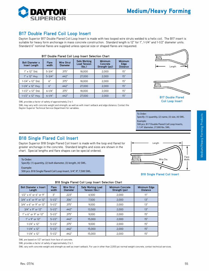
5512/15
Med
ium
/Hea
vy F
orm
ing
Pro
duct
s
Medium/Heavy Forming
B17 Double Flared Coil Loop InsertDayton Superior B17 Double Flared Coil Loop Insert is made with two looped wire struts welded to a helix coil. The B17 insert is suitable for heavy form anchorage in mass concrete construction. Standard length is 12" for 1", 1-1/4" and 1-1/2" diameter units. Standard 6" nominal flares are supplied unless special size or shaped flares are requested.
B17 Double Flared Coil Loop Insert Selection Chart
Bolt Diameter x Insert Length
Flare width
Wire Strut Diameter
Safe Working Load Tension
(lbs.)
Minimum Concrete
Strength (psi)
Minimum Edge
Distance
1" x 12" Std. 5-3/4" .375" 18,000 2,000 15"
1" x 12" Hvy. 5-3/4" .442" 27,000 2,000 15"
1-1/4" x 12" Std. 6" .375" 18,000 2,000 15"
1-1/4" x 12" Hvy. 6" .442" 27,000 2,000 15"
1-1/2" x 12" Std. 6-1/4" .375" 18,000 2,000 15"
1-1/2" x 12" Hvy. 6-1/4" .442" 27,000 2,000 15"
SWL provides a factor of safety of approximately 2 to 1.SWL may vary with concrete weight and strength, as well as with insert setback and edge distance. Contact the Dayton Superior Technical Service Department for variables.
B18 Single Flared Coil InsertDayton Superior B18 Single Flared Coil Insert is made with the loop end flared for greater anchorage in the concrete. Standard lengths and sizes are shown in the chart. Special lengths and flare shapes can be special ordered.
B18 Single Flared Coil Loop Insert Selection Chart
Bolt Diameter x Insert Length
Flare width
Wire Strut Diameter
Safe Working Load Tension (lbs.)
Minimum Concrete Strength (psi)
Minimum Edge Distance
1/2" x 4" or 6" or 9" 3" .223" 4,500 2,000 11"
3/4" x 6" or 9" or 12" 5-1/2" .306" 7,500 2,000 13"
3/4" x 6" or 9" or 12" 5-1/2" .375" 9,000 2,000 13"
3/4" x 9" or 12" 5-1/2" .442" 13,500 2,000 13"
1" x 6" or 9" or 12" 5-1/2" .375" 9,000 2,000 15"
1" x 9" or 12" 5-1/2" .442" 15,000 2,000 15"
1-1/4" x 12" 5-1/2" .375" 9,000 2,000 15"
1-1/4" x 12" 5-1/2" .442" 15,000 2,000 15"
1-1/4" x 12" 5-1/2" .442" 15,000 2,000 15"
SWL are based on 1/2" set back from face of concrete.SWL provides a factor of safety of approximately 2 to 1.SWL vary with concrete weight and strength as well as insert setback. For use in other than 2,000 psi normal weight concrete, contact technical services.
To Order:Specify: (1) quantity, (2) bolt diameter, (3) length, (4) SWL.
Example:500 pcs. B18 Single Flared Coil Loop Insert, 3/4", 9", 7,500 SWL.
Length
Flare�WidthWire Dia.
B18 Single Flared Coil Insert
To Order: Specify: (1) quantity, (2) name, (3) size, (4) SWL.
Example:500 pcs. B17 Double Flared Coil Loop Inserts, 1-1/4" diameter, 27,000 lbs. SWL.
B17 Double Flared Coil Loop Insert
Length
Length
Wire Dia.Flare Width
Rev. 07/16
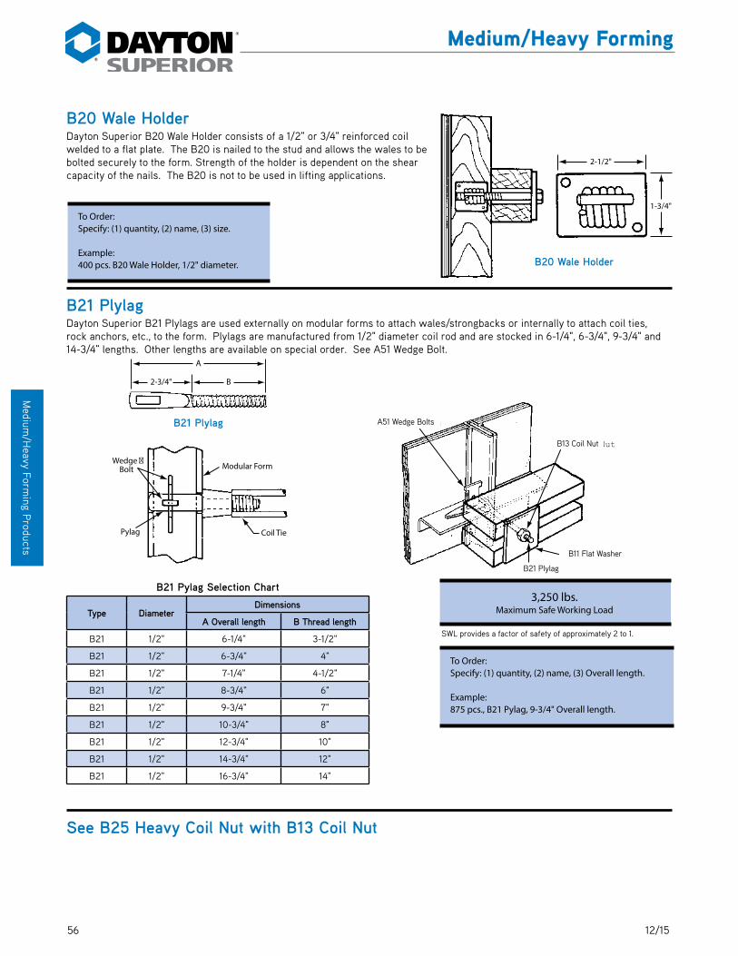
56 12/15
Medium
/Heavy Form
ing Products
Medium/Heavy Forming
B20 Wale HolderDayton Superior B20 Wale Holder consists of a 1/2" or 3/4" reinforced coil welded to a flat plate. The B20 is nailed to the stud and allows the wales to be bolted securely to the form. Strength of the holder is dependent on the shear capacity of the nails. The B20 is not to be used in lifting applications.
B21 PlylagDayton Superior B21 Plylags are used externally on modular forms to attach wales/strongbacks or internally to attach coil ties, rock anchors, etc., to the form. Plylags are manufactured from 1/2" diameter coil rod and are stocked in 6-1/4", 6-3/4", 9-3/4" and 14-3/4" lengths. Other lengths are available on special order. See A51 Wedge Bolt.
B21 Pylag Selection Chart
Type DiameterDimensions
A Overall length B Thread length
B21 1/2" 6-1/4" 3-1/2"
B21 1/2" 6-3/4" 4"
B21 1/2" 7-1/4" 4-1/2"
B21 1/2" 8-3/4" 6"
B21 1/2" 9-3/4" 7"
B21 1/2" 10-3/4" 8"
B21 1/2" 12-3/4" 10"
B21 1/2" 14-3/4" 12"
B21 1/2" 16-3/4" 14"
See B25 Heavy Coil Nut with B13 Coil Nut
2-1/2"
1-3/4"
B20 Wale Holder
To Order:Specify: (1) quantity, (2) name, (3) size.
Example:400 pcs. B20 Wale Holder, 1/2" diameter.
3,250 lbs.Maximum Safe Working Load
To Order:Specify: (1) quantity, (2) name, (3) Overall length.
Example:875 pcs., B21 Pylag, 9-3/4" Overall length.
SWL provides a factor of safety of approximately 2 to 1.
Wedge �Bolt
Pylag
Modular Form
Coil Tie
A
2-3/4" B
B21 Plylag
B21Plytag
B11 Flat W asher
B13 Coil Nut
A51 W edge Bolts
B21 Plylag
B13 Coil Nut
B11 Flat Washer
A51 Wedge Bolts

5712/15
Med
ium
/Hea
vy F
orm
ing
Pro
duct
s
Medium/Heavy Forming
B27 and D6 Nut WasherDayton Superior B27 and D6 Nut Washers combine the advantages of a washer and nut into a one-piece ductile iron unit. The nut washer is equipped with nailing holes to secure them to the formwork and are designed to spread the forming loads over the wood forming members. The B27 Nut Washer has coil thread in the sizes displayed in the chart and can be used with all appropriate coil threaded devices. The D6 Nut Washer is equipped with Acme thread and is normally used with the D2 She-Bolt.
B27 and D6 Nut Washer Selection Chart
TypeThread Safe Working
Load Tension (lbs.)
DDiameter Type
B27 1/2" Coil 4,500 4"
B27 3/4" Coil 9,000 4"
B27 7/8" Coil 12,000 5"
B27 1" Coil 18,000 5"
D6 3/4" Acme 9,000 4"
SWL provides a factor of safety of approximately 2 to 1.
B29 Loose Plastic ConeDayton Superior B29 Loose Plastic Cones are used with B1 and B2 Coil Ties. They are placed on the coil bolts after the coil bolts have been inserted through the form face but prior to threading the bolt into the coil tie. The large end of the cone provides suf-ficient bearing surface to prevent crushing of the plywood around the bolt hole. B29 plastic cones are removed from the concrete with a B15 Cone Removal Wrench and can be reused.
B29 Loose Cone Selection Chart
BoltDiameter
Setback(Cone Length)
AB C
1/2" 1" 1-1/4" 1"
1/2" 1-1/2" 1-1/4" 1"
1/2" 2" 1-1/4" 1"
3/4" 1" 1-5/8" 1-7/16"
3/4" 1-1/2" 1-5/8" 1-7/16"
3/4" 2" 1-5/8" 1-7/16"
1" 2-1/2" 2-1/8" 1-3/4"
1-1/4" 2-1/2" 2-3/8" 2-1/8"
SWL provides a factor of safety of approximately 2 to 1.
Warning: Cones are to be used for spreader action only and are not designed for scaffold bracket or other accessory loads.
To Order:Specify: (1) quantity, (2) name, (3) diameter, (4) thread type.
Example:100 pcs., B27 Nut Washer, 1/2" coil thread.
A
A Setback
B1 or BCoil Tie
B C
Setback =Cone Length
3/4" 1 5/8"
D
B27 Nut Washer
B29 Plastic Cone
To Order:Specify: (1) quantity, (2) name, (3) bolt diameter, (4) setback.
Example:2,000 pcs. B29 Loose Plastic Cone, 1/2", 2" setback.
Setback = Cone Length
B1 or B2 Coil Tie
Setback

58 12/15
Medium
/Heavy Form
ing Products
Medium/Heavy Forming
B30 Screw-On Plastic ConesDayton Superior Screw-On Plastic Cones are designed to thread onto the protruding coil of a B3 Screw-On Coil Tie. Use a B15 Cone Removal Wrench to back the cone off the tie and out of the concrete. B30 plastic cones are normally reusable.
B30 Screw-On Selection Chart
Bolt Dia. Setback A B C
1/2" 1" 1-3/8" 1-1/4" 1"
1/2" 1-1/2" 1-7/8" 1-1/4" 1"
1/2" 2" 2-3/8" 1-1/4" 1"
3/4" 1" 1-1/2" 1-5/8" 1-7/16"
3/4" 1-1/2" 2" 1-5/8" 1-7/16"
3/4" 2" 2-1/2" 1-3/4" 1-7/16"
3/4" 3" 3-1/2" 1-7/8" 1-7/16"
1" 1" 1-1/2" 2-1/8" 1-13/16"
1" 2" 2-1/2" 2-1/8" 1-13/16"
1-1/4" 2" 2-1/2" 2-3/8" 2-1/8"
Warning: Cones are to be used for spreader action only and are not designed for scaffold bracket or other accessory loads.
B31 Rock AnchorDayton Superior B31 Rock Anchor is a preassembled unit tapped with 1/2", 3/4" or 1" diameter coil thread. NC thread is available on special order. Rock anchors used in sound rock or concrete allows one-sided forming of walls or similar applications to be completed quickly and economically.
The rock anchor is threaded onto the coil rod until the rod hits the backstop of the anchor. The plastic retaining sleeve is removed and the rock anchor/coil rod assembly is placed into the bore hole. The assembly is installed so that the anchor backstop “bottoms” in the bore hole. Tightening the coil rod will draw the anchor wedges forward to expand the anchor’s shell. Care should be taken to not overtighten the anchor.
B31 Rock Anchor Selection Chart
Coil Rod Diameter
Minimum Hole Depth “L” *
Required Hole Diameter
“D”
Safe Working Load Tension
(lbs.) **
1/2" 6" 1-3/8" 4,500
3/4" 8" 1-5/8" 9,000
1" 10" 1-3/4" 18,000
SWL provides a factor of safety of approximately 2 to 1 in 3,500 psi concrete.
*NOTE: It is extremely important to drill the proper size bore hole for the appropriate rock anchor. Avoid “dog leg” or “rifled” holes, they will hinder anchor installation. It is also important to avoid letting the drill dwell at the bottom of the hole. This can cause an enlargement at the bottom of the hole and result in a loss of anchorage strength.
The bore hole for the rock anchor must be drilled perpendicular to the exposed bearing surface. The load carrying capacity of the rock anchor is greatly reduced when there is an angle between the nut on the coil rod and the bearing surface.
The B31 Rock Anchor is not a reusable device. After the rock anchor has been set and the forming completed, do not attempt to reuse the rock anchor.
**WARNING: For safe construction practice, the most critical factor to consider is the actual anchorage capacity provided by the rock strata or concrete in which the rock anchor is to be installed. Correct hole depth and actual rock anchor capacity must always be determined by field tests before placing rock anchors into general use on a project.
MinimumCoil Penetration
Coil Tie
B12Coil Rod
Rock Anchor
L
D
Back Sto
Wedge
Plastic Retainer �Sleeve (remove)
Shell
B31 Rock Anchor
To Order:Specify: (1) quantity, (2) name, (3) coil rod diameter.
Example:600 pcs. B31 Rock Anchor, 1/2" coil thread.
A
Setback
B3 Coil Tie
B C
B30 Screw-On Plastic Cone
B3 Coil Tie
Setback
Rock AnchorMinimum Coil Penetration
Plastic Retainer Sleeve (remove)
Coil Tie
Shell
Wedge
Back Stop
B 12 Coil Rod
07/16

5912/15
Med
ium
/Hea
vy F
orm
ing
Pro
duct
s
Medium/Heavy Forming
B32 Handle Coil NutDayton Superior B32 Handle Coil Nut is a B13 Hex Coil Nut which has a wire loop handle welded to it. It is designed for use in situ-ations which require quick application or removal of a nut. It speeds up installation and stripping of formwork.
B32 Handle Coil Nut Selection Chart
Diameter Safe Work LoadTension (lbs.)
1/2" 4,500
3/4" 9,000
1" 18,000
1-1/4" 27,000
SWL provides a factor of safety of approximately 2 to 1.
B33 Double Flared Criss Cross Coil Loop InsertDayton Superior B33 Double Flared Criss Cross Coil Loop Insert consists of two flared wire loops welded to a helix coil. B33 inserts are available in 1", 1-1/4" and 1-1/2" diameters and are used in conjunction with the D40 He-Bolt for form anchorage.
B33 Double Flared Criss Cross Coil Loop Insert Selection Chart
Bolt Dia. x
Insert Length
Safe Working Load Tension
(lbs)
Concrete Strength
(psi)
Minimum Edge
Distance
Dimensions
A B C D E F
1" x 12-3/8" 18,000 2,000 15" 12-3/8" 2-1/16" 2-1/16" .375" 5-9/16" 5-9/16"
1" x 12-1/2" 27,000 2,000 15" 12-1/2" 2 1/4" 2-1/16" .442" 5-3/4" 5-3/4"
1-1/4" x 12-3/8" 18,000 2,000 15" 12-3/8" 2 5/16" 2-1/16" .375" 5-9/16" 5-9/16"
1-1/4" x 12-1/2" 27,000 2,000 15" 12-1/2" 2 1/2" 2-1/16" .442" 5-3/4" 5-3/4"
1-1/2" x 12-3/8" 18,000 2,000 15" 12-3/8" 2 9/16" 2-3/8" .375" 5-9/16" 5-9/16"
1-1/2" x 12-1/2" 27,000 2,000 15" 12-1/2" 2 3/4" 2-3/8" .442" 5-3/4" 5-3/4"
SWL are based on 1/2" setback from face of concrete.SWL provides a factor of safety of approximately 2 to 1.SWL vary with concrete weight and strength as well as insert setback. For use in other than 2,000 psi normal weight concrete, contact our technical service department.
A
EFB
C D
To Order:Specify: (1) quantity, (2) name, (3) diameter.
Example:600 pcs. B32 Handle Coil Nut, 1/2” coil thread.
2"
5 1/4"35"
B32 Handle Coil Nut
To Order:Specify: (1) quantity, (2) name, (3) bolt dia. (4) length, (5) safe working load, (6) plain or Electroplated.
Example:450 pcs. B33 Double Flared Criss Cross Coil Loop Insert, 1" x 12-3/8" long, 18,000 lbs. SWL, plain.

60 12/15
Medium
/Heavy Form
ing Products
Medium/Heavy Forming
B37 Toggle TieDayton Superior B37 Toggle Tie is used to tie one-sided formwork to steel sheet pilings. The tie requires a 1-3/8" hole in the sheathing to permit entry of the tie. The toggle tie can also be welded to the sheathing. Refer to safety information on the inside front cover concerning welding operations.
The B37 Toggle Coil Tie is available in 1/2" diameter only.
B39 Wing NutDayton Superior B39 Wing Nut is made of ductile iron and can be used for any application requiring quick removal and application of a nut.
B39 Wing Nut Selection Chart
Coil Rod Diameter
Safe Working Load Tension (lbs.) A B C D
1/2" 9,000 5" 1-1/4" 2-3/8" 1-3/8"
3/4" 18,000 5-7/8" 1-1/4" 2-1/2" 1-3/4"
7/8" 18,000 6" 1-5/8" 2-3/4" 1-3/4"
1" 38,000 6" 1-5/8" 3" 2"
1-1/4" 52,000 5-5/8" 1-5/8" 2-3/4" 2-1/4"
1-1/2" 80,000 6-3/4" 1-7/8" 2-3/4" 2-7/8"
SWL are based on 1/2" setback from face of concrete.Note: Wing nuts may vary slightly in configuration from that shown.
To Order:Specify, (1) quantity, (2) name, (3) diameter
A
D
Coil�Rod�Dia.
C
B
Minimum Coil�Penetration
Weld �Both Sides
Steel�Sheet�Piling
Length 1"
1" x 1/2" x 1/8"�Steel Channel
1-1/2"
4"
3,750 lbs.Maximum Safe Working Load
To Order:Specify: (1) quantity, (2) name, (3) length.
Example:700 pcs. B37 Toggle Tie, 18-1/2" length.
Length
1" x 1/2" x 1/8" Steel Channel
Minimum Coil Penetration
Weld Both Sides
Steel Sheet Piling
Coil Rod Dia.

6112/15
Med
ium
/Hea
vy F
orm
ing
Pro
duct
s
Medium/Heavy Forming
B40 Plastic Setback PlugDayton Superior B40 Plastic Setback Plugs seal the hole left when Screw-On Cones are removed from the concrete. Plugs are available for use with 1/2" diameter coil ties setback 1" or 1-1/2" from the concrete face, and are stocked in light and dark grey to blend with the natural color of the concrete. Contrasting colors are available on special order.
B42 and D22 Batter WasherDayton Superior Batter Washers are used when the wales are at an angle to the ties. Permits any angle from 90˚ to 45˚. For use with B39 Wing Nut.
Nail holes are provided for securing to wood form members.
B42 and D22 Batter Washer Selection Chart
TypeBolt
DiameterHole
DiameterA B C
B42 1/2" 9/16" 3-9/16" 3" 1"
B42 3/4" 7/8" 4-3/4" 4-1/4" 1-9/16"
D22 1" 1-1/16" 6-3/4" 5-1/4" 1-3/4"
D22 1-1/4"-1-3/8" 1-5/8" 6" 7" 1-7/8"
D22 1-1/2"-1-5/8" 1-3/4" 6-1/2" 7-3/4" 2-1/8"
B43 Triple Flared Coil Loop InsertDayton Superior B43 Triple Flared Coil Loop Insert consists of three flared wire loops welded to a helix coil. B43 inserts are avail-able in 1-1/4" diameter and are used in conjunction with a D40 He-Bolt in form anchorage applications.
B43 Triple Flared Loop Insert Selection Chart
TypeBolt Dia.
xInsert Length
Safe WorkingLoad Tension
(lbs.)
ConcreteStrength
(psi)
Dimensions
A B C D E F
B43 1-1/4" x 12"/15" 34,000 2,000 15" 2-1/2" 2-1/16" .440" 5-3/4" 5-3/4"
SWL are based on 6" setback from face of concrete and 32" minimum edge distance.
SWL provides a factor of safety of approximately 2 to 1 in normal weight concrete.
SWL vary with concrete weight and strength as well as insert setback and minimum edge distance. For use in other than 2,000 psi concrete, contact our technical service department.
To Order:Specify: (1) quantity, (2) name, (3) bolt size.
Example:200 pcs. B42 Batter Washer, 3/4" bolts.
To Order:Specify: (1) quantity, (2) name, (3) length.
Example:500 pcs. B43 Triple Flared Coil Loop Insert, 12" long.
A
EFB
C
D
To Order:Specify: (1) quantity, (2) name, (3) color.
Example:2,000 pcs. B40 Plastic Setback Plugs, light gray.
1/2" for 1" Setback�3/4" for 1-1/2" Setback
B-3 Coil Tie
Plastic�Setback�
PlugB40 Plastic Setback Plug
B42 Batter Washer
Hole Diameter
B3 Coil Tie
1/2" for 1" Setback 3/4" for 1-1/2" Setback
D22 Batter Washer
C
A B

62 12/15
Medium
/Heavy Form
ing Products
Medium/Heavy Forming
D1 and D18 Inside Tie RodsInside tie rods are used with she-bolts to provide a highly adapt-able forming system. The inside tie rods are made from high carbon steel with coil threads. National coarse threads can be provided on special order.
The correct inside tie rod length is determined by subtracting the total required setback (both sides) from the wall thickness. Flats are available to prevent turning of the inside tie rods in the con-crete and are recommended for wall thickness of 24" or less.
D1 or D18Inside Tie Rod
Inside RodLength
Setback Setback
W all Thickness
To Order:Specify: (1) quantity, (2) name, (3) diameter (4) O.A. length, (5) with flat or crimp.
Example:800 pcs. D1 Inside Tie Rod with Coil Threads, 3/4" diameter, 22" long, with flat.
Flat-Location May Vary
Thread Length
Inside Rod Length
D1 Inside Tie Rod
Inside Rod Length�Thread Length
D18 Inside Tie Rod
D1 and D18 Inside Tie Rod Selection Chart
TypeSafe Working Load Tension
(lbs)
Inside Tie Rod Dimensions
Thread Diameter Thread Type Thread
LengthMinimum Length
Maximum Length
D1 9,000 1/2" N.C. or Coil 1-1/4" 5", 6" with flat 20'-0"
D18 9,000 1/2" Coil Continuous 5" 20'-0"
D1 12,000 5/8" N.C. or Coil 1-3/4" 5", 6" with flat 12'-0"
D18 12,000 5/8" Coil Continuous 5" 20'-0"
D1 18,000 3/4" N.C. or Coil 1-3/4" 5", 6" with flat 12'-0"
D18 18,000 3/4" Coil Continuous 5" 20'-0"
D1 38,000 1" N.C. or Coil 2-1/4" 5", 6" with flat
D18 38,000 1" Coil Continuous 5"
SWL provides a factor of safety of approximately 2 to 1.7/8", 1-1/8", 1-1/4" and 1-1/2" and D18 Inside Rods are available on special order.See D33 for water resistant washer for D1 Inside Tie Rods.
Inside Rod Length
Inside Rod Length
Thread Length
Thread Length
Flat Location May Vary
SetbackSetback
Wall Thickness
Inside Rod Length
D1 or D18 Inside Tie Rod

6312/15
Med
ium
/Hea
vy F
orm
ing
Pro
duct
s
Medium/Heavy Forming
D1J, D1LA and D1L Hook BoltsHook Bolts are used with She-Bolts in concrete forming applications. The standard hook wraps around rebar or other steel to allow for blind wall forming.
Hook Bolt Selection Chart
D Coil Thread Diameter
NC Thread Diameter Minimum T Minimum AISI
Number (Ref.)
1/2" 1/2" 1" 1018
3/4" 3/4" 1-1/2" 1018
D1S Anchor Bolt SleeveDayton Superior D1S Anchor Bolt Sleeve allows one size sleeve to accommodate two or more anchor bolt diameters. The unique high-density polyethylene plastic design provides flexibility and reduces inventory requirements. If sizing is required, simply cut the sleeve at the gage line as shown.
Anchor Bolt Sleeves provide a grout pocket around the anchor bolt to allow the bolt to be positioned exactly. They provide a quick, easy way to make final adjustments and a clean pocket for grouting at lower cost than other methods.
D1S Anchor Bolt Sleeve Sizes and Color Code
Color Code Shell Size (in.) Bolt Diameter
Yellow 2 x 5 1/2", 3/4"
White 2 x 7 5/8", 3/4", 7/8"
Green 3 x 10 1", 1-1/4"
Red 4 x 15 1-1/2", 1-3/4"
Blue 4 x 18 2", 2-1/4"
Brown 6 x 24 2-1/2", 3"
Black 6 x 24 4”, 5"
To Order:Specify: (1) quantity, (2) name, (3) shell size.
Example:100 pcs. D1S Anchor Bolt Sleeve, 2" x 7" shell size.
To Order:Specify: (1) quantity, (2) name, (3) thread type, (4) then dimensions of the bent bolt in the order indicated by the dimension letters in brackets below each illustration.
Example:500 pcs. D1J Hook Bolt, Round Bend 1/2" coil thread, L = 12", C = 1-1/2", A = 3", T = 1", and R = 3/4".
L
A
TC
D
D1J Hook Bolt, Round Bend(L, C, A, T)
Available with 1/2", 5/8", 3/4", or 7/8" Coil or NC threads
L
TC
D
R+
D1L, Hook BoltRight Angle Bend
(L, C, T, R)
L
TC B
D
R+
D1LA Hook Bolt, Special(L, C, A, R, B)
B expressed in degrees
06/16

64 12/15
Medium
/Heavy Form
ing Products
Medium/Heavy Forming
D2 and D30 She-BoltsDayton Superior D2 and D30 She-Bolts are heavy duty, reusable form ties for medium and heavy concrete construction. The D2 She-Bolt has a 3/4" diameter and is equipped with Acme thread. The D30 She-Bolt has coil thread and is available in 3/4" through 1-5/8" diameters in 1/8" increments. She-Bolts are used in conjunction with D1 or D18 Inside Rods to form tie a wide range of formwork thickness.
D2 and D30 She-Bolt Selection Chart
Type
SafeWorking
LoadTension
(lbs)
She-Bolt External Thread Inside Tie Rod
A B C D E LExternal
Hardware RequiredDiameter Type Thread
Diameter Type
D2 9,000 3/4" Acme 1/2" NC 5/8" 1/2" 1-1/4" 3/4" 3" 20" 3/4" Dia. D6
D30 9,000 7/8" Coil 1/2" Coil 1" 1/2" 1-1/2" 7/8" 2-3/4" 18" 20" 24" 7/8" Dia B27 or B39
D30 12,000 7/8" Coil 5/8" Coil 1" 1/2" 1-1/2" 7/8" 2-3/4" 18" 20" 24" 7/8" Dia. B39
D30 18,000 1-1/4" Coil 3/4" Coil 1" 3/4" 2" 1-1/4" 4" 20" 24" 30" 35" 1-1/4" Dia B39.
D30 37,500 1-1/2" Coil 1" Coil 1" 3/4" 2" 1-1/2" 4" 20" 24" 30" 35" 1-1/2" Dia B39
D30 56,000 1-1/2" Coil 1 1/4" Coil 1" 3/4" 2-3/4" 1-3/4" 4" 20" 24" 30" 35" 1-1/2" Dia B39
Note: She-Bolts are meant to be reused, but they do wear, so they must be continually inspected. When wear or damage is noted, they must be replaced. SWL provides a factor of safety of approximately 2 to 1.A water proof grease should be applied to the embedded portion of the she-bolt to facilitate removal.Standard sizes are listed in the chart, other than standard sizes are available on special order.Caution: The pitch (threads/inch) of the 3/4" diameter Acme thread varies in certain geographical areas of the United States, please check before ordering.
D1 or D18Inside Tie Rod
Inside RodLength
Setback Setback
She-Bolt
B11Flat W asher
Nut W asher
B39Wing Nut
W all Thickness
To Order:Specify: (1) quantity, (2) name, (3) diameter, (4) length, (5) tapped for diam-eter of inside coil or NC threaded rods.
Example:200 pcs. D2 She-Bolt, 3/4" diameter, 20", O.A. length, tapped for 1/2" inside rods with coil threads.
L�Standard Lengths
A
ETapered�
Nose10"
C
B
D
D2, D30 She-Bolt
L�Standard Lengths
A
ETapered�
Nose10"
C
B
DA
30˚�
D30 High Strength She-Bolt
Standard Length Standard Length
Tapered Nose
Tapered Nose
Setback
She-Bolt
Setback
Wall Thickness
Nut Washer
Inside Rod Length
D1 or D18 Inside Tie Rod
B11 Flat Washer
B39 Wing Nut

6512/15
Med
ium
/Hea
vy F
orm
ing
Pro
duct
s
Medium/Heavy Forming
D4 Hex Coupling NutDayton Superior D4 Hex Coupling Nuts are used to splice D1 Inside Tie Rods. Threads are right hand national course and will accept standard machine bolts. In order to develop the rated load you must make certain that you have equal engagement of the inside threaded rods or bolts. Hex coupling nut is not provided with a center stop.
See D6 Nut Washer information with B27
D9 Taper TiesDayton Superior D9 Taper Ties are used where spec-ifications require or permit complete removal of the form tie from the concrete. Standard taper ties are supplied with coil thread in the diameters and lengths shown in the chart. Other lengths are available on special order.
A complete taper tie assembly consists of one taper tie, two flat washers and two appropriate nut devices. Standard taper ties are manufactured with a taper up to 30" in length. Longer tapers are available on special order.
For wrench turning purposes, taper ties are manufactured with a square end. On the opposite end (smaller end) is designed with a protruding nose to prevent thread damage during the removal operation. Coating the taper tie with waterproof grease will facilitate taper tie removal.
Note: Taper ties will wear and get damaged. They must be continually inspected and replaced if wear or damage is noted.
D9 Taper Ties Selection Chart
Safe Working Load Tension (lbs.)
Large End of Tie Small End of TieStandard Tie
LengthsTapered Body
DiameterCoil Thread Diameter
Length of Thread
Coil Thread Diameter
Length of Thread
7,500 3/4" 10" 1/2" 2" 34", 43", 52" .670" to .500"
18,000 1" 10" 3/4" 6"30", 36", 42", 48",
54", 60", 72"
.884" to .750"
34,000 1-1/4" 10" 1" 6" 1.113" to 1.00"
50,000 1-1/2" 10" 1-1/4" 6" 1-1/2" to 1-1/4"
75,000 H.S. 1-3/4" 10" 1-1/2" 6" 36", 48", 60", 72" 1-3/4" to 1-1/2"
SWL provides a factor of safety of approximately 2 to 1.
Studs
W all Thickness
B11Flat W asher
B39Wing Nut
B39Wing Nut
W ales
D4 Hex Coupling Nut Selection Chart
National Course
Thread Dia.A B C
Safe Working Load Tension
(lbs.)
3/8" 1-3/4" 5/8" 11/16" 3,750
1/2" 1-3/4" 11/16" 3/4" 9,000
5/8" 2-1/8" 13/16" 1-5/16" 12,000
3/4" 2-1/4" 1" 1-1/8" 18,000
1" 2-3/4" 1-3/8" 1-9/16" 36,000
SWL provides a factor of safety of approximately 2 to 1.
To Order:Specify: (1) quantity, (2) name, (3) thread diameter.
Example:2,000 pcs. D4 Hex Coupling Nuts, 1/2" thread.
To Order:Specify: (1) quantity, (2) name, (3) diameter, large and small, (4) O.A. length.
Example:250 pcs. D9 Taper Ties, 1-1/4" dia. to 1" dia., 54" O.A. length.
A
C
B
D4 Hex Coupling Nut
Wales
Studs
Wall Thickness
B11 Flat Washer
B39 Wing NutB39 Wing Nut

66 12/15
Medium
/Heavy Form
ing Products
Medium/Heavy Forming
Allow 9" forTighteningWrench and Clamp
Rod Clamp
D14TighteningWrench
Allow 4"Past W ale,Bend Rodat 90˚
D12 Rod Clamp
D9A D/R Thread Bar Taper TieDayton Superior D/R Thread Bar Taper Ties (D9A) are used when specifications require or permit complete removal of the form tie from the concrete. The D9A features the D/R Thread Bar’s 2-1/2 threads per inch for rapid installation and stripping. Standard 5/8" and 7/8" diameter taper ties are available in the sizes shown in the chart. See B12A D/R Thread Bar.
D12 Rod ClampsDayton Superior D12 Rod Clamps are cast malleable iron clamps used with smooth or deformed 1/4", 3/8" and 1/2" rod to tie forms. The rod is clamped securely by a bolt or nut/bolt combination. Nail holes are provided to affix the clamp to the wales. For an addi-tional safety measure, Dayton Superior recommends bending the rod approximately 90˚ behind the clamp (See application sketch)
D9A 5/8" Taper Tie
Taper L1 L2 L3** L4** Safe Working Load
1" to 5/8"
42" 16"
11-1/2" 11-1/2" 18,750 lbs.50" 24"
58" 32"
*Safe Working Load based on approximate 2 to 1 safety factor** Standard thread length shown, other lengths available on request.
D9A 7/8" Taper Tie
Taper L1 L2 L3** L4** Safe Working Load
1-1/4"
to 7/8"
42" 16"
11-1/2" 11-1/2" 32,500 lbs.50" 24"
58" 32"
66" 40"
*Safe Working Load based on approximate 2 to 1 safety factor** Standard thread length shown, other lengths available on request.
L1 Overall Length
L2L3 L4 1" Typ.
D9A D/R Thread Bar Taper Tie
To Order:Specify: (1) quantity, (2) name, (3) diameter, (4) overall length, (5) L3 and/or L4 lengths, if other than standard.
Example:250, D9A D/R Thread Bar Taper Ties, 7/8" dia. X 66" overall length.
D12 Rod Clamp Selection Chart
TypeRod
DiameterSafe Working Load
Tension (lbs.)
D12 1/4" 1,125
D12 3/8" 2,250
D12 1/2" 3,750
SWL provides a factor of safety of approximately 2 to 1.
To Order:Specify: (1) quantity, (2) name, (3) size.
Example:500 pcs. D12 Rod Clamp, 1/4".
Allow 4" Past Wale,
Bend Rod at 90°
Rod Clamp
Allow 9" for Tightening Wrench and
Clamp
D14 Tightening
Wrench
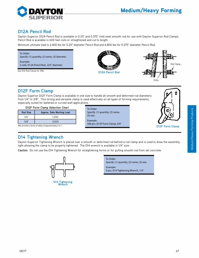
6712/15
Med
ium
/Hea
vy F
orm
ing
Pro
duct
s
Medium/Heavy Forming
D12A Pencil RodDayton Superior D12A Pencil Rod is available in 0.25" and 0.375" mild steel smooth rod for use with Dayton Superior Rod Clamps. Pencil Rod is available in 600 feet coils or straightened and cut to length.
Minimum ultimate load is 2,400 lbs for 0.25" diameter Pencil Rod and 6,800 lbs for 0.375" diameter Pencil Rod.
D12F Form ClampDayton Superior D12F Form Clamp is available in one size to handle all smooth and deformed rod diameters from 1/4" to 3/8". This strong and versatile clamp is used effectively on all types of forming requirements, especially suited for battered or curved wall applications.
D12F Form Clamp Selection Chart
Rod Size Approx. Safe Working Load
1/4" 1,250
3/8" 3,000SWL provides a factor of safety of approximately 2 to 1.
D14 Tightening WrenchDayton Superior Tightening Wrench is placed over a smooth or deformed rod behind a rod clamp and is used to draw the assembly tight allowing the clamp to be properly tightened. The D14 wrench is available in 1/4" size.
Caution: Do not use the D14 Tightening Wrench for straightening forms or for pulling smooth rod from set concrete.
D14 TighteningWrench
To Order:Specify: (1) quantity, (2) name, (3) size.
Example:5 pcs. D14 Tightening Wrench, 1/4".
D12F Form Clamp
To Order:Specify: (1) quantity, (2) name, (3) size.
Example:500 pcs. D12F Form Clamp, 3/8"
See D12 Rod Clamp for SWL
To Order:Specify: (1) quantity, (2) name, (3) diameter.
Example:2 coils, D12A Pencil Rod, .225" diameter.
D12A Pencil Rod
D12A
Rod ClampRod Clamp
D12A
08/17

68 12/15
Medium
/Heavy Form
ing Products
Medium/Heavy Forming
See D18 Inside Tie Rod with D1 info
D21 Rebar Clip and Form SpreaderDayton Superior D21 Rebar Clip and Form Spreader was developed to serve as a combination form spreader and rebar spacer when the forming does not provide internal spreading action. The D21 spreader is available for any wall thickness and rebar cover. It will assure walls of proper thickness and will increase the speed of placing the rebar. The ends of the spreader are plastic protected to resist corrosion and to prevent marring of the form face.
See D22 Batter Washer with B42
D24 Weld Angle BracketDayton Superior D24 Weld Angle Bracket is designed to tie one sided forming to steel piles, metal beams, weld plates, etc. The pivot pin is furnished with coil or D/R thread, NC thread is available on special order.
The D24 allows the form tie a pivot range of 110˚ (55˚ each direction) and exceeds the tensile capacity of the form tie when properly installed by a certified welder. See safety note concerning welding inside back cover.
Warning: To insure proper thread engagement the form tie must penetrate beyond the pivot bar a minimum of one diameter (the diameter of the form tie being used). An easy way to accomplish this is to position the form tie perpendicular to the piling and thread it through the pivot bar until it contacts the piling.
To Order:Specify: (1) quantity, (2) name, (3) rebar diameter, (4) wall thickness, (5) distance between centerline of rebar and face of concrete.
Example:200 pcs. D21 Rebar Clip and Form Spreader for #4 Rebars, A=16" wall, C = 2-1/4".
A
C
B
110˚ Maximum�Adjustment
H
110° Maximum Adjustment
Wall Thickness
CCCL CL
D21 Rebar Clip and Form Spreader Typical Application
Wall Thickness
45˚� 30˚� 15˚� 0˚� 15˚�
.70
x SW
L
.86
x SW
L
.96
x SW
L
1.0
x SW
L
.96
x SW
L
.86
x SW
L
.70
x SW
L
30˚� 45˚�
D24 Weld Angle Bracket Selection ChartCoil Thread Diameter
Maximum Safe Working Load Tension (lbs.)* A B C H
1/2" 9,000 6" 2-1/4" 4" .250"5/8" 10,500 6" 2-1/4" 4" .250"3/4" 18,000 6" 2-1/4" 4" .250"7/8" 25,000 6" 2-1/4" 4" .250"1" 31,500 6" 3-1/16" 5" .375
1-1/8" 42,500 6" 3-1/16" 5" .375"5/8" D/R 22,400 6" 2-1/4" 4" .250"7/8" D/R 39,200 6" 3-1/16" 5" .250
*Actual SWL depends on the strength of the field weld, coil rod used and angle between the coil rod and the weld plate.
To Order:Specify: (1) quantity, (2) name, (3) diameter.Example:200 pcs. D24 Weld Angle Bracket, 1" diameter.
Inside Tie Rod
W ood Lagging
Double W alesSized per LoadRequirements
Batter W asher
She Bolt
B39Wing Nut
Structural Steel
Batter Washer
Wood Lagging
Inside Tie Rod
She-Bolt
Structural Steel
B39 Wing Nuts
Double Wales Sized per Load Requirements
Rev. 08/17

6912/15
Med
ium
/Hea
vy F
orm
ing
Pro
duct
s
Medium/Heavy Forming
D25 Fitting Up Bolt and D26 Fitting Up NutDayton Superior Special Fitting Up Bolts and Nuts are used for securing steel form panels together–available in 3/4" diameter x 2" long. The tapered nose of the bolt acts as a draft pin and helps align the forms. The thread design and clearances between the nut and bolt permits quick assembly and dismantling of the forms. The open thread design permits concrete to be easily knocked out of the threads.
D25 Fitting Up Bolt and D26 Fitting Up Nut
Item Diameter Length Grade Packaging
D25 Bolt 3/4" 2" SAE Grade 5 Sold only in setsof 400 pcs.D26 Nut 3/4" – ASTM A194 Grade 2H
D27 Lag BoltD27 Lag Bolt is designed to provide a temporary means of attaching formwork to wood timbers. Typical application is one-sided blind forming against steel soldier piles with wood lagging. Safe Working Load is approximately 1,700 lbs. (treated wood) and 2,500 lbs. (untreated wood) with 2:1 safety factor. SWL depends on quality of lumber. Lag bolts should have full thread engagement to carry the required load.
Product Code Diameter Length Thread Weight
143551 3/4" 5" LONG 1/2" NC Thread 0.51 LB
D25Fitting Up Bolt
D26 Fitting Up Nut
D27 Lag Bolt
Typical Application
To Order:Specify: (1) quantity, (2) name.Example:800 pcs. D25 Fitting Up Bolts and D26 Fitting Up Nuts.

70 12/15
Medium
/Heavy Form
ing Products
Medium/Heavy Forming
D30A D/R Thread Bar She-BoltDayton Superior D/R Thread Bar She-Bolts (D30A) are heavy duty, reusable form ties for medium and heavy concrete construction. The D30A features the D/R Thread Bar's 2-1/2 threads per inch for rapid installation and stripping. Two She-Bolts are used with a length of B12A D/R Thread Bar to tie formwork for any wall thickness. D30A She-Bolts are available in the sizes and lengths shown in the chart. Other sizes available on request.
D30A 5/8" and 7/8" She-Bolts
Nom. Size Overall Length D L1 L2 Taper Safe Working
Load
5/8" 18" or 24" 3/4" 7-3/4" 4" 1" to 7/8"22.400
5/8" 18" or 24" 1-1/4" 7-3/4" 4" 1-1/4" to 1-1/8"
7/8" 18" or 24" 1-1/2" 7-3/4" 4" 1-1/2" to 1-3/8" 39,200
*SWL provides a factor of safety of approximately 2 to 1.
D32 Closed CouplerDayton Superior D32 Closed Coupler is available with coil threads for use with D1 and D18 Inside Tie Rods or B12 Coil Rod. The coil threads have been tapped from each end of the coupler providing a positive stop at the center of the coupler. In order to develop the rated load, the inside tie rods or coil rods must be threaded into the coupler until they reach the stop. Other sizes are available on special order.
Unique ApplicationA D32 Closed Coupler for 3/4" diameter inside tie rod will engage a tie rod in the cavity left by a she-bolt. Can be used for anchorage or to form a second pour.
D33 Water Resistant WasherDayton Superior D33 Water Resistant Washers are neoprene washers used on D1 Inside Rods to break the continuity of the tie to help eliminate water seepage along the tie.
Generally specified when she-bolts are used to form water containment structures.
D32 ClosedCoupler 3/
B
A
D32 Closed Coupler
To Order:(1) quantity, (2) name, (3) diameter, (4) nominal size, (5) overall length, (6) taper.Example:200, D30A D/R Thread Bar She-Bolts, 5/8" nom. size with 1-1/4" to 1-1/8" taper.
D32 Closed Coupler Selection Chart
Coil Thread Diameter
LengthA
Dia.B
Safe Working Load Tension (lbs.)
1/2" 2-3/4" 3/4" 9,000
5/8" 3-1/4" 1" 12,000
3/4" 3-1/4" 1-1/8" 18,000
7/8" 4-1/4" 1-3/8" 31,000
1" 4-1/2" 1-1/2" 37,500
1-1/8" 5-1/4" 1-3/4" 45,000
1-1/4" 5-3/4" 1-7/8" 56,000
1-1/2" 7" 2-1/8" 67,500
SWL provides a factor of safety of approximately 2 to 1.
1/4"
A
W asher LocationM ay Vary
D
D33 Water Resistant Washer
D33 Water Resistant Washer Selection ChartInside Tie Rod Diameter “A” “D”
1/2" Coil 0.397" 1"5/8" Coil 0.5 1.25"
5/8" Euro Bar 0.5 1.25"5/8" D/R Bar 0.563 1.5"
3/4" Coil 0.625" 1.5"7/8" Coil 0.75 1.5"
7/8" D/R Bar 0.75 1.5"1" Coil 0.84" 1.5"
1-1/4" Coil 1.085 1.75
Washer Location May Vary
D30A D/R Thread She-Bolt
07/16

7112/15
Med
ium
/Hea
vy F
orm
ing
Pro
duct
s
Medium/Heavy Forming
D40 He-BoltsDayton Superior D40 He-Bolts provide an economical and flexible anchor-ing system for use with cantilevered forms in mass concrete construction. Lifts of 5 to 10 ft. can be economically anchored without changing hard-ware. He-Bolts are produced with a taper to permit easy removal.
He-Bolts are designed to be reused – however they will wear and must be continually inspected and replaced when wear or damage is noted. A waterproof grease should be applied to that portion of the bolt which will be embedded into the concrete to facilitate removal.
Length As Required
T As Required
B
A
E
D HG
F
D40 He-Bolts
To Order:Specify: (1) quantity, (2) name, (3) diameter, (4) O.A. length, (5) required T dimension.
Example:500 pcs. D40 He-Bolts, 1-1/4" diameter, 28" long, T=10".
D40 He-Bolt Selection Chart
Size Maximum Safe Working Load Tension (lbs.)
Maximum H Diameter Safe Working Load Shear (lbs.) A B D E F Coil Thread
Diameter GCoil Thread Diameter H
1-1/4" 34,000 22,600 1" 3/4" 1-1/4" 5" 3-1/2" 1-1/4" 1"
1-1/2" 50,000 33,300 1" 1" 1-1/2" 5" 3-1/2" 1-1/2" 1-1/4"
SWL provides a factor of safety of approximately 2 to 1.
Insert MinimumEdge Distan
InsertSetback
CantileverForm Panel
ConstructionJoint
B11Flat
W asher
B39WingNut
D40He-Bolt
MassConcrete
T as Required
D40 He-Bolt
Length as Required
Mass Concrete
B39 Wing Nut
Cantilever Form Panel
Insert Minimum Edge Distance
Construction Joint
Insert Setback
B1 Flat Washer

72 12/15
Medium
/Heavy Form
ing Products
Medium/Heavy Forming
Typical He-Bolt AnchorsThese Dayton Superior anchors are effectively used in conjunction with the D40 He-Bolt to anchor cantilever forms. The B18 Single Flared Coil Loop Insert is recommended for 5' lifts, the B33 Double Flared Coil Loop Insert is recommended for 5' to 7-1/2' lifts and the B43 Triple Flared Coil Loop Insert is recommended for 7-1/2' to 10' lifts.
• See B18 Single Flared Coil Loop Insert.
• See B33 Double Flared Coil Loop Insert.
• See B43 Triple Flared Coil Loop Insert.
Special He-Bolt InsertsSpecial inserts can be manufactured to meet your unusual forming requirements. Please contact a Dayton Superior Technical Service Department with your requirements. Several special inserts that have been developed are shown below.
D42 Bag TiesDayton Superior Bag Ties (D42) are 16 gauge, annealed loop-ended wire ties used for tying rebar and other non-construction applications, such as bags and carpet rolls. D42 Bag Ties are avail-able in 4", 5", 6", 7", 8", 10" and 12" lengths. Other lengths and gauges are available on special order. D42 Bag Ties are sold by the bag or pallet only. 4" through 8" lengths are packaged in coils of 1,000 pieces, five coils per bag (5,000 pcs.). 10" and 12" lengths are packaged 2,500 pieces per bag.
B18 Single Flared Coil Loop Insert
B7 Two StrutB22 Four Strut
B34-4Four Strut
Four StrutDraped Insert
B33 Double Flared Coil Loop Insert B43 Triple Flared Coil Loop Insert
To Order:Specify: (1) quantity, (2) name, (3) bolt diameter, (4) length, (5) safe working load, (6) finish (plain or Electroplated).Example:450 pcs. B18 Single Flared Coil Loop, 1" x 9" long, 9,500 lbs. SWL, plain.
D42 Bag TiesTo Order:Specify: (1) quantity, (2) name.
Example:5 bags (25,000 pcs.), D42 Bag Ties.

7312/15
Med
ium
/Hea
vy F
orm
ing
Pro
duct
s
Medium/Heavy Forming
PC110 Impalement Safety Cap• Protects workers from protruding rebar
• Impalement protection
• One size fits #4 — #9 rebar
• Safety orange color
• Fully tested and approved (CAL-OSHA #C-1716AG)
• Meets Cal OSHA max. drop test requirements
• Complies with Cal OSHA, Section 1712
D46 Tie WireDayton Superior Tie Wire (D46) is 16 gauge black, annealed wire used for tying rebar or similar applications. D46 Tie Wire is
packaged twenty (20) 3-1/2 pound coils per carton (approx. 385 feet per coil). Available only in full cartons or in 48 carton pallets.
D48 Sure-Guard Rebar Protective CapThe Dayton Superior D48 Sure-Guard Rebar Protective Caps have been developed to protect workmen from the hazards of pro-truding rebar. The D48 cap is available in all rebar sizes, and packaged in bags of 50.
D46 Tie Wire
To Order:Specify: (1) quantity (sold by carton and/or skid only), (2) name.
Example:5 cartons, D46 Tie Wire
To Order:Specify: (1) quantity, (2) name, (3) bar size.
Example:600, D48 Sure-Guard Rebar Protective Caps for #6 rebar.
D48 Sure-Guard Rebar Protector
PC110 Impalement Safety Cap

74 12/15
Medium
/Heavy Form
ing Products
Medium/Heavy Forming
A58 Sure PlugThe Sure Plug is easily pushed into a hole the specified depth by using the A59 Insertion Tool. The A58 Sure Plug should be installed ONLY with the A59 Insertion Tool. Pushing against the bottom of the blind center hole of the plug forces the plug’s oversize body to elongate as it enters the hole. When the pushing force is stopped, the plug elastically returns towards its original diameter creating a high radial pressure against the walls of the hole. When properly installed, the A58 Sure Plug will withstand a hydrostatic pressure equal to approximately a 277 ft. liquid head of water. Test report is available on request.
As the plug is gray colored to blend with concrete, it may be positioned flush with the concrete face, or recessed, depending on the architectural effect desired. Depending on how the A59 insertion tool is adjusted, it will install the plug either flush to the surface or approximately a 1-1/2" maximum depth.
When recessed, the Sure Plugs may also serve as backing for flush or recessed grouting. Ribs inside the plug are designed to anchor the grout.
A58 Sure Plug is not intended to be installed to the center of a wall and attempts to do so can in most cases rupture the plug.
A59 Insertion ToolUsed to insert A58 Sure Plugs flush with face of concrete or recessed to various depths.
Note: Please specify plug size when ordering insertion tool.
A59 Insertion Tool
To Order:Specify: (1) quantity, (2) name, (3) plug size.
Example:20 pcs. A59 Insertion Tool, size 14.
A58 Sure Plug
To Order:Specify: (1) quantity, (2) name, (3) plug size.
Example:500 pcs. A58 Sure Plug, size 11.
A58 Sure Plug Selection Chart
Plug Size
Nominal Hole Diameter Plug Length
11 11/16" 1"
14 7/8" 1-1/8"
16 1" 1-1/4"
18 1-1/8" 1-3/8"
20 1-1/4" 1-3/8"
22 1-3/8" 1-1/2"
24 1-1/2" 1-1/2"
28 1-3/4" 1-5/8"
29 1-7/8" 1-5/8"

7512/15
Med
ium
/Hea
vy F
orm
ing
Pro
duct
s
Medium/Heavy Forming
F1 Screw Anchor and F2 Screw Anchor BoltF1 Screw Anchors are excellent for re-anchor of forms and have been used for years. The flat wire of the anchor, in full contact with the bolt threads, transfers the load into the surrounding concrete. The screw anchor must be threaded onto the bolt and locked against the skein threads of the bolt by a hard twist. The screw anchor is the most economical insert to use when depth of embedment is available.
The safe working loads shown can only be developed when the assembled bolt and anchor is embedded at least ten times the bolt diameter. If the screw anchor is inserted after the concrete is placed, the concrete must be thoroughly vibrated in order to develop the safe working loads.
CAUTION: The Screw Anchor Bolt is not interchangeable with either a Coil Bolt or National Course Bolts.
For ease of bolt removal, coat screw anchor bolts with a water resistant grease. It is important that the bond between the bolt and concrete be broken by twisting the bolt at least one turn as soon as the concrete has reached a compressive strength of 1,000 to 1,500 psi.
F1 Screw Anchor Selection Chart
Bolt Dia. ASTM A307 with Skein
Threads
Safe WorkingLoad (lbs.) Concrete Strength
(psi)
Minimum Edge
Distance
Dimensions
Tension Shear A B C
3/4" 8,200 5,400 3,000 9" 4" 3-1/2" 1-1/4"
1" 15,400 10,200 3,000 11" 6" 4" 1-1/2"
1-1/4" 23,000 15,300 3,000 13" 7" 5-1/2" 2"
1-1/2" 35,000 23,200 3,000 17" 8" 7" 2-1/4"
1-3/4" and 2" F1 and F2 are available on special order.SWL provides a factor of safety of approximately 2 to 1.
F2 Screw Anchor Bolt
Bolt Length
Set 1/2" dia. deeper�for final tightening
Grip of Object�to be BoltedBA
C
Assembled Bolt and Anchor(A&B Must Equal Ten Times Bolt Dia.)
F1 Screw Anchor
To Order:Specify: (1) quantity, (2) name, (3) size, (4) finish (Plain or Electroplated).
Example:1,000 pcs. F1 Screw Anchors, 3/4" diameter, Electroplated.
To Order:Specify: (1) quantity, (2) name, (3) diameter of bolt, (4) length of bolt, (5) finish (Plain or Electroplated).
Example:50 pcs. F2 Screw Anchor Bolts, 3/4" diameter, 8" long, Electroplated.
Grip of Object to be Bolted
Bolt Length
Set 1/2" dia. deeper for final tightening

76 12/15
Medium
/Heavy Form
ing Products
Medium/Heavy FormingNotes and Sketches
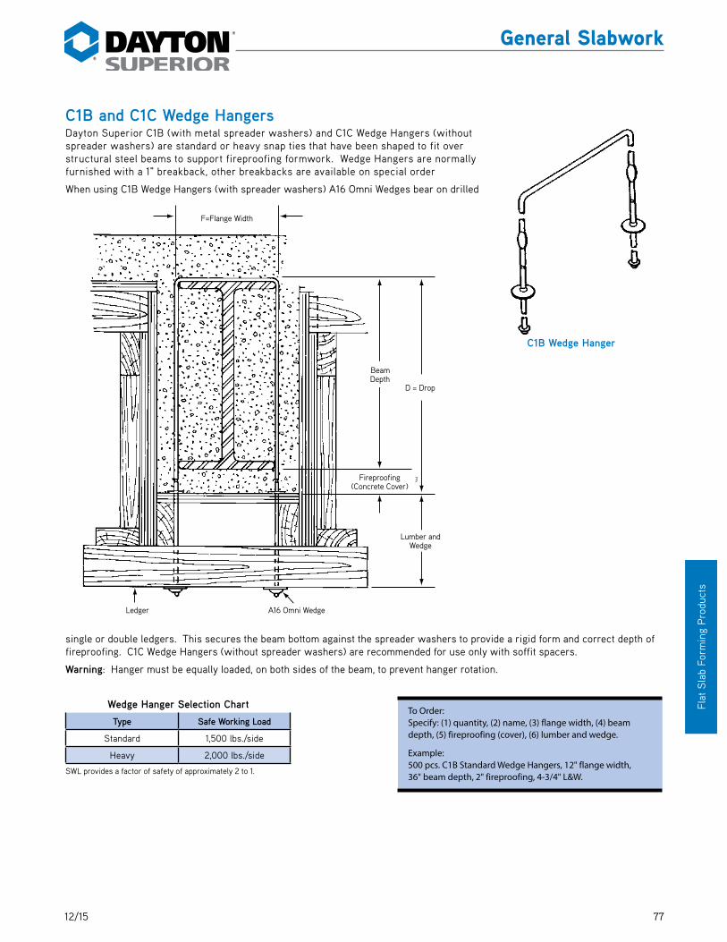
7712/15
Flat
Sla
b Fo
rmin
g P
rodu
cts
General Slabwork
C1B and C1C Wedge HangersDayton Superior C1B (with metal spreader washers) and C1C Wedge Hangers (without spreader washers) are standard or heavy snap ties that have been shaped to fit over structural steel beams to support fireproofing formwork. Wedge Hangers are normally furnished with a 1" breakback, other breakbacks are available on special order
When using C1B Wedge Hangers (with spreader washers) A16 Omni Wedges bear on drilled
single or double ledgers. This secures the beam bottom against the spreader washers to provide a rigid form and correct depth of fireproofing. C1C Wedge Hangers (without spreader washers) are recommended for use only with soffit spacers.
Warning: Hanger must be equally loaded, on both sides of the beam, to prevent hanger rotation.
Wedge Hanger Selection Chart
Type Safe Working Load
Standard 1,500 lbs./side
Heavy 2,000 lbs./side
SWL provides a factor of safety of approximately 2 to 1.
C1B Wedge Hanger
To Order:Specify: (1) quantity, (2) name, (3) flange width, (4) beam depth, (5) fireproofing (cover), (6) lumber and wedge.
Example:500 pcs. C1B Standard Wedge Hangers, 12" flange width, 36" beam depth, 2" fireproofing, 4-3/4" L&W.
F = Flange Width
Ledger A16 Omni W edge
Lumberand W edge
D
BeamDepth
Fireproofing(Concrete Cover)
F=Flange Width
Fireproofing (Concrete Cover)
A16 Omni WedgeLedger
Lumber and Wedge
Beam Depth
D = Drop
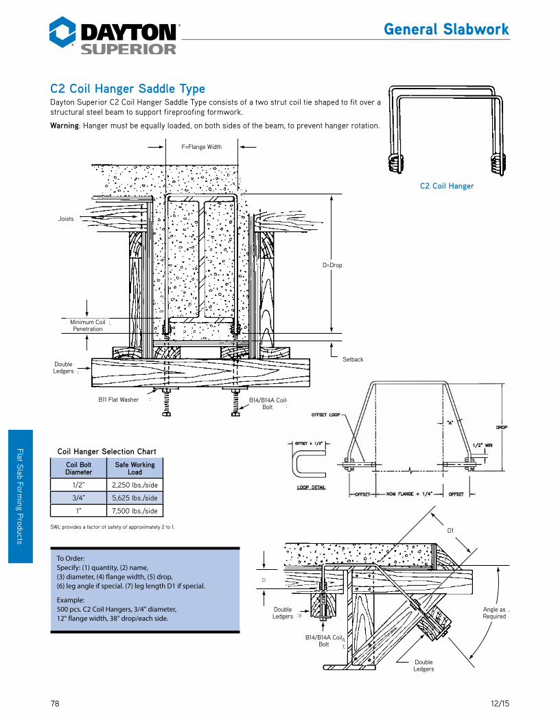
78 12/15
Flat Slab Form
ing Products
General Slabwork
C2 Coil Hanger Saddle TypeDayton Superior C2 Coil Hanger Saddle Type consists of a two strut coil tie shaped to fit over a structural steel beam to support fireproofing formwork.
Warning: Hanger must be equally loaded, on both sides of the beam, to prevent hanger rotation.
Coil Hanger Selection Chart
Coil Bolt Diameter
Safe Working Load
1/2" 2,250 lbs./side
3/4" 5,625 lbs./side
1" 7,500 lbs./side
SWL provides a factor of safety of approximately 2 to 1.
C2 Coil Hanger
To Order:Specify: (1) quantity, (2) name, (3) diameter, (4) flange width, (5) drop, (6) leg angle if special. (7) leg length D1 if special.
Example:500 pcs. C2 Coil Hangers, 3/4" diameter, 12" flange width, 38" drop/each side.
B14 / B14ACoil Bolt
DoubleLedgers
Angle AsRequired
D1
DoubleLedgers
D
D1
B14/B14A Coil Bolt
Double Ledgers
Double Ledgers
Angle as Required
F = Flange Width
B14 / B14ACoil Bolt
Setback
B11 Flat W asher
D = Drop
DoubleLedgers
Minimum CoilPenetration
Joists
F=Flange Width
D=Drop
B11 Flat Washer
Setback
B14/B14A Coil Bolt
Joists
Double Ledgers
Minimum Coil Penetration

7912/15
Flat
Sla
b Fo
rmin
g P
rodu
cts
General Slabwork
C3 Coil Half HangerDayton Superior C3 Coil Half Hangers are two strut coil hangers used on exterior structural steel beams. The free end is designed to be welded to the beam flange, or if welding is not permitted, can be bent around and back under the beam flange for a distance of approximately 2".
See safety note on inside of cover pertaining to welding.
C3 Coil Half Hangers are designed for light duty loads only. Safe working load is dependent on the strength of bend or field weld. Tests should be conducted in the field to determine actual safe working loads before implementation.
Double�Ledgers
Edge Angle
Joists
Weld to�Beam Flange
D = Drop
Minimum Coil Penetration
�
F = As Specified
C3 Coil Half Hanger
To Order:Specify: (1) quantity, (2) name, (3) diameter, (4) F dimension, (5) drop.
Example:500 pcs. C3 Half Hangers, 1/2" dia., 12" F dimension, 6" drop.
F=Flange Width
D=Drop
Joists
Edge Angle
Weld to Beam Flange
Double Ledgers
Minimum Coil Penetration

80 12/15
Flat Slab Form
ing Products
General Slabwork
C13 Plate Saddle HangerDayton Superior C13 Plate Saddle Hanger is primarily used with steel beam construction but can be used effectively on precast beams and concrete block walls. No working parts or adjustments are required. Just hang the hanger over a beam, insert the joists over the plates and lay plywood. The bearing plates are 1/2" wide and are fixed in position by swaging the wire. Standard plates are available for 2x4 and 4x4 SAS dressed lumber. C13 hangers are available with any drop dimension and any beam width over 2" and with heavy duty 4 gauge wire. C13 hangers are recommended for use with lumber joists only and should not be utilized to support metal joists.
Joist lumber should extend past the hanger bearing support a minimum of 2".
Warning: Hanger must be equally loaded on both sides to prevent unequal loading and resulting rotation of the hanger.
Special Application: This application requires care to ensure adequate lumber bearing on the hanger. Use duplex head nail behind the hanger plate to prevent the joist from slipping off of the hanger plate. Continuous inspec-tion, before and during concrete placement, is required.
Plywood
Minimum 2"
Steel Beam�Type
Joist To Order:Specify: (1) quantity, (2) name, (3) flange width, (4) drop, (5) joist lumber.
Example:1,200 pcs. C13 Plate Saddle Hanger, standard 12" flange width, 8-1/4" drop, 2x lumber.
1,500 lbs. for C13Safe Working Loads
SWL provides a factor of safety of approximately 2 to 1.
Recommended for use with lumber joists only.
Total�Drop
Joist
Beam Width
C13 Plate Saddle Hanger
Total Drop
Joist
Beam Width
Joist
Plywood
Minimum 2"
Steel Beam Type
Plywood
Minimum 1-1/2"
NOTE: Duplex Head Nail� Behind Plate
Joist
Special Application
Joist
Plywood
Minimum 1-1/2"
NOTE: Duplex Head Nail Behind Plate

8112/15
Flat
Sla
b Fo
rmin
g P
rodu
cts
General Slabwork
C13A All-Wire Saddle HangerDayton Superior C13A All-Wire Saddle Hanger is formed from a single wire and butt-welded over the flange area. Wire sizes, working loads and applications are similar to the C13 hanger, above. The C13A hanger is recommended for lumber joists only. Do not utilize for metals joists. See warning note below.
Warning: Soft wood joists will crush in the area of the wire, even under light loads. Tests show that the wood will crush approximately 1/8" at 300 pounds per side; approximately 1/4" at 500 pounds each side and up to 3/4" at 1,000 pounds each side.
Warning: Hangers must be equally loaded, on both sides of the beam, to prevent rotation of the hanger.
C14 Channel HangerDayton Superior C14 Channel Hanger is similar to the C13 hanger with the exception of channels instead of plates to support the wood joists. The chan-nels increase the safe working load on the hanger and help reduce crushing of the wood. Soft wood joists may crush up to 3/16" at safe working loads.
Warning: Hanger must be equally loaded, on both sides of the beam, to prevent hanger rotation.
Special Application: This application requires care to ensure adequate lumber bearing on the hanger. Use duplex head nail behind the hanger plate to prevent the joist from slipping off of the hanger plate. Continuous inspection, before and during concrete placement, is required..
Plywood
Minimum 1-1/2"
NOTE: Duplex Head Nail� Behind Plate
Joist
Special Application
Joist
Minimum 1-1/2"
NOTE: Duplex Head Nail Behind Plate
Plywood
Minimum 2"
Steel Beam�Type
Joist
To Order:Specify: (1) quantity, (2) name, (3) wire size, (4) width, (5) drop, (6) joist lumber.
Example:800 pcs. C13A All-Wire Saddle Hanger, 4 ga., 12" width, 8-1/4" drop, for 4" x 8" joist. Recommended for use with lumber joists only.
To Order:Specify: (1) quantity, (2) name, (3) width, (4) drop, (5) joist lumber.
Example:800 pcs. C14A All-Wire Saddle Hanger, 12" width, 8-1/4" drop, for 4" x 8" joist.
2,250 lbs. per sideSafe Working Loads
SWL provides a factor of safety of approximately 2 to 1.
Joist
Minimum 2"
Steel Beam Type
Total�Drop
Joist
Beam Width
C14 Channel Hanger
Joist
Total Drop
Beam Width
Total�Drop Weld
Joist
Beam Width
C13A All-Wire Saddle Hanger
Total Drop
Beam Width
Joist
Weld

82 12/15
Flat Slab Form
ing Products
General Slabwork
PAS Aztec® Screed ChairFor elevated slabs and slabs on grade.
• Fits 2x4 lumber or 1-1/2" diameter pipe screeds
• Includes a base, adjustable ring and a screed receiver
• Designed to allow up to ±1" in height adjustment
• 1" O.D. PVC pipe (not included) can be cut to any height
• 300 lb. safe working load compression
Methods of Screeding
Chair Size Chart
Screed ChairDimensions Cradle Head
Adjust. Length in
Slab-1" Pipe Slab-1-1/2" Pipe Suggested Working Load less than 1/10"
Def. lbs.Height in. Width in. Min. in. Max. in. Min. in. Max. in.
G2
1"* 2-3/4" 1"* 2-1/4" 2-3/4" 2-1/4" 2-3/4" 900
1-1/2" 2-3/4" 1-1/2" 3" 3-1/2" 3-1/2" 4" 900
1-1/2" 2-3/4" 2-1/2" 3-3/4" 4-1/2" 4-1/4" 5" 900
G2
2-1/2" 3-1/2" 3" 4-1/2" 6" 5" 6-1/2" 800
3-1/2" 4-1/2" 4” 5-1/2" 8" 6" 8-1/2" 900
4-1/2" 4-1/2" 4" 6-1/2" 9" 7" 9-1/2" 850
5-1/2" 4-1/2" 6" 7-1/2" 12" 8" 12-1/2" 800
7-1/2" 7-1/2" 8" 9-1/2" 16" 10" 16-1/2" 600
10" 7-1/2" 12" 13-1/2" 22-1/2" 14" 23" 500
*1" Cradle Head accepts 3/4" screed pipe, only.
Spacing Chart
Screed Pipe or Bar
Spacing*
Hand Screeding Using 1/2"Diameter Screed Bases
Machine Screeding Using 3/4"Diameter Screed Bases
Screed Length Base Spacing Screed Length Base Spacing
3/4" I.D. Pipe 8'-0" to 10'-0" 3'-0" to 4'-0" – –
1" I.D. Pipe 8'-0" to 10'-0" 4'-0" to 5'-0" 10'-0" to 12'-0" 2'-0" to 2'-6"
1-1/4" or 1-1/2" I.D. Pipe 10'-0" to 12'-0" 4'-0" to 6'-0" 12'-0" to 15'-0" 2'-6" to 4'-0"
1/2" x 1-1/2" Flat Bar 8'-0" to 10'-0" 3'-0" to 4'-0" – –
1-1/4" x 1-1/4" x 3/16" T-Bar 8'-0" to 10'-0" 4'-0" to 5'-0" – –
2" x 2" x 1/4" T-Bar 10'-0" to 12'-0" 4'-0" to 6'-0" 12'-0" to 15'-0" 2'-6" to 4'-0"
* Spacings are approximate. Judgement of field conditions, weight of screeds, etc., will control.
Screed Pipe�in Slab
Typical Screed Detail
1.
Adjusting to Grade1. Turn base for final adjustment.2. Turn coil nut for final adjustment on “free-fit” type bases.
2.
Screed Pipe in Slab
PRODUCT CODE QTY/BOX WT. LBS.
PER BOX
123568 100 17

8312/15
Flat
Sla
b Fo
rmin
g P
rodu
cts
General Slabwork
G1 Pipe HolderDayton Superior G1 Pipe Holder is designed to be used with 1/2" or 3/4" screed chairs to support pipe screed bars. Standard lengths and adjustment ranges are shown in the accompanying table on previous page.
G1U Special U-Shaped Cradle HeadDayton Superior G1U Special U-Shaped Cradle Head is designed for use with a flat screed bar or other similar shapes. G1U holders are available in the same lengths as the G1 holder, above.
G2 Screed Chair BasesDayton Superior G2 Screed Chair Bases are available in two styles in 1/2" and 3/4" nominal diameters. Refer to the chart on previ-ous page for pertinent dimensions. G2 bases are used in conjunction with G1 or G1U cradle heads to support screed pipes or bars.
G2J Joist Type Adjustable Screed BaseDayton Superior G2J Joist Type Adjustable Screed Base is used with bar joist and rib lath construc-tion. Two of the legs are bent down to penetrate the lath on both sides of the joist while the other two legs rest flat on top of the lath. Standard heights are 1" and 1-1/2". Special heights are available on special order.
To Order:Specify: (1) quantity, (2) name, (3) diameter, (4) length.
Example:800 pcs. G1 Pipe Holder, 1/2" diameter, 4" long
To Order:Specify: (1) quantity, (2) name, (3) diameter (4) height.
Example:2,000 pcs. G2 Screed Chair Bases, 1/2" diameter, 1-1/2" height.
To Order:Specify: (1) quantity, (2) name, (3) diameter, (4) length.
Example:1500 pcs. G1U Special U-Shaped Cradle Head, 1/2", 6" long.
Length
Any base
G1 Pipe Hold
G1 Pipe Holder
For 1" & 1-1/2"�Heights Only
G2 Screed Chair Bases
Length
G1U Special U-Shaped Cradle Head
To Order:Specify: (1) quantity, (2) name, (3) diameter, (4) height.
Example:1500 pcs. G2J Joist Type Adjustable Screed Base, 1/2", 1-1/2" height.
G2J Joist Type Adjustable Screed Base
Length
Length
Any Base
G1 Pipe Holder
For 1" and 1-1/2" Heights Only

84 12/15
Flat Slab Form
ing Products
General Slabwork
G2S Special Height Screed BaseDayton Superior G2S Special Height Screed Base can be fabricated to any desired height over 7". The G2S base is fabricated with substantial wire legs laced together with wire cross-braces. Lacing height (dimension “L”) is 2" on bases up to 9" in height and 4" on bases over 10".
G3 Screed Chair Base With Sand PlateDayton Superior G3 Screed Chair Base with Sand Plate is designed for use on fill dirt over vapor barriers or on special materials that are not to be penetrated.
G4 and G4A Screed Bases, Drive TypeDayton Superior G4 and G4A Screed Bases, Drive Type are recommended for use on fill where greater bearing is required. The G4 base offers increased stabi l i ty with its extended legs which are driven into the fill. G4 bases are available in standard 2-1/2", 3-1/2", and 5-1/2" heights with taller bases available on special order.
The G4A base is fabricated with heavier wire that allows it to be driven into most sub-grades. The G4A is available in standard 1-1/2", 2-1/2", 3-1/2" and 5-1/2" heights with taller bases available on special order.
To Order:Specify: (1) quantity, (2) name, (3) diameter, (4) height.
Example:1500 pcs. G2S Special Height Screed Base, 1/2", 9" height.
To Order:Specify: (1) quantity, (2) name, (3) diameter, (4) height.
Example:1500 pcs. G4 Screed Chair Base Drive Type, 1/2", 3-1/2" height.
To Order:Specify: (1) quantity, (2) name, (3) diameter, (4) height.
Example:1500 pcs. G3 Screed Chair Base with Sand Plate, 1/2", 6" height.
3-3/8"
G-4 Screed�Chair Base�Drive Type
Height
Type G4 Screed Base
8" Minimum
4"
G-4-A Screed�Chair Base�Drive Type
Height
Type G4A Screed Base
“L”�
G2S Special Height Screed Base
G3 Screed Chair Base with Sand Plate
1"
Height
Height
8" Minimum
3-3/8"
G4A Screed Chair Base Drive Type

8512/15
Flat
Sla
b Fo
rmin
g P
rodu
cts
General Slabwork
G5 Screed Bases, Free Fit TypeG5 Screed Bases, Free Fit Type can be furnished with an oversize, slip-fit ferrule. This arrange-ment allows for adjustment without turning the base or the cradle head. Adjustment is obtained by turning the jam nut.
G7 Screed Chair Base for Steel DeckDayton Superior G7 Screed Chair Base for Steel Deck is a 1" high screed base designed with wide bearing struts to ade-quately span the corrugations of metal decking. The G7 base is available in two versions; one spans flush with the lands of the decking while the other sets down into the valley.
G8 Form BracketDayton Superior Form Bracket (G8) consists of a 1/2" or 3/4" coil thread nut welded to a steel plate.
The bracket can be nailed or welded to a joist to support a screed bolt extending through the decking or used with a form bolt to support and position a curb form.
To Order:Specify: (1) quantity, (2) name, (3) style.
Example:400 pcs. G7 Screed Chair Base for Steel Deck, flush style.
To Order:Specify: 1) quantity, (2) name, (3) diameter.
Example:150, G8 Form Brackets, 1/2" diameter.
Valley Style
G-7 Screed�Chair Base�
for Steel Deck
Flush Style
G7 Screed Chair Base Application
Form Bolt
Form Bracket
G8 Form Bracket
G5 Screed Base, Free Fit Type
G7 Screed Chair Base For
Steel Deck
16 Ga. Tie (by others)
G6 Screed Chair Base
Free Fite Type
Flush StyleWelby Style

86 12/15
Flat Slab Form
ing Products
General Slabwork
G11 Screed Stake for PipeDayton Superior G11 Screed Stake for Pipe is designed to be driven into the subgrade to support 1" screed pipe. G11 stakes are available in 15" and 18" lengths.
G14 Heavy Duty Screed HoldersDayton Superior G14 Heavy Duty Screed Holders consist of a rolled steel plate welded to a length of 1" diameter coil rod. The G14 screed holder is used with a free-fit screed base to support screed pipe of various sizes.
The “open style” is fabricated from grade 11 gauge steel and is limited to 2" O.D., or smaller, pipe. The “closed style” is fabricated from 1/4" steel and is fitted with two 3/8" diameter set screws. The closed style holder can accommodate screed pipe up to 3" O.D. Both styles are available in 4-1/4", 6-3/4" and 9-3/4" lengths with one Coil Nut included with each holder.
G15 Heavy Duty Screed SupportDayton Superior G15 Heavy Duty Screed Support is available in 1" and 1-1/4" diameters in 3", 4" and 6" heights. G15 screed supports are welded to a steel beam to provide a receptacle for a cradle head to support the screed pipe. Adjustment is accomplished by turning the jam nut on the cradle head.
To Order:Specify: (1) quantity, (2) name, (3) length.
Example:200 pcs. G11 Screed Stakes, 18" long.
To Order:Specify: (1) quantity, (2) name, (3) style, (4) length.
Example:200 pcs. G14 Heavy Duty Screed Holders, closed style, 9-1/4" long.
Bias Cut End
Length
G11 Screed Stake
1" Dia. �Standard
11 Ga.
2" O.D. Pipe�(maximum)
1" Dia. �Standard
1/4" Thick
G14 Heavy Duty Screed Holders
To Order:Specify: (1) quantity, (2) name, (3) length.
Example:200 pcs. G15 Heavy Duty Screed Support, 6" long.
Cradle Head
Screed�Support
Jam Nut
Weld to �Beam
G15Heavy Duty Screed
Support
Length
1/4" Thick
11 Ga.
2" O.D. Pipe Minimum
1" Dia. Standard
1" Dia. Standard
Screed Support
Weld to beam
Jam NutCradle Head
Bias Cut End

8712/15
Flat
Sla
b Fo
rmin
g P
rodu
cts
General Slabwork
G16 Heavy Duty Screed Chair BaseDayton Superior G16 Heavy Duty Screed Chair Base is a rigid support designed for heavy vibratory screed applications. G16 bases are available with standard 1" and 1-1/4" coils or free-fit ferrules. Standard heights for the G16 base are 4-1/2", 5-1/2", 7-1/2" and 10".
G27 Round StakeDayton Superior G27 Round Stakes are manufactured from high quality steel with a sharp point to minimize rock deflection. G27 stakes are available in 3/4" and 7/8" diameters and in standard lengths of 12", 18", 24", 30", 36", 42" and 48". The G27 stake is available with spiral-patterned nail holes or without holes for use as form pins.
Dayton Superior G26 Stake Puller is available for easy removal of the G27 Round Stakes. Contact a Dayton Superior Service Center or dealer for price and availability.
G28 and G29 Screed BracketDayton Superior G28 and G29 Screed Brackets clamp to the top of a nail stake and hold screed bar parallel to the form during flatword finishing. Screed brackets are available for 1/2"x2" flat bar and 2x4s. G28 is used with 3/4" round nail stakes and G29 is used with 3/4" square nail stakes.
To Order:Specify: (1) quantity, (2) name, (3) diameter, (4) height.
Example:200 pcs. G16 Heavy Duty Screed Chair Base, 1" dia., 7-1/2" height.
To Order:Specify: (1) quantity, (2) name, (3) diameter, (4) length, (5) with or without nail holes.
Example:360 pcs. G27 Round Stakes, 3/4" diameter, 18" long, with nail holes. G27 Round StakeG26 Stake Puller
G28 Screed Bracket G29 Screed Bracket
1-3/4" 1-3/4"
1-3/4" 1-3/4"
G16 Heavy Duty Screed G16 Heavy Duty Screed Chair
Both Available with Coil Thread or Free Fit

88 12/15
Flat Slab Form
ing Products
General Slabwork
G33 Screed Key JointDayton Superior G33 Screed Key Joint is 24 gauge steel available in 10' lengths in heights of 3-1/2", 4-1/2" and 5-1/2" for use in 4", 5" and 6" on-grade concrete floor slabs. G33 meets ASTM A653 G40 Type B mill galvanized requirements. Screed Key produces a smooth, flush surface joint that requires no filling. The use of Screed Key Joint minimizes random cracking and provides proper load transfer from slab to slab.
The use of Screed Key Joint is more economical than bulk-headed forms that must be prepared, installed, stripped, cleaned, repaired or replaced and stored. With Screed Key Joint an entire slab or strips can be poured at one time. Costly and time-consuming checker boarding is eliminated. Install the Screed Key Joint and pour the concrete - finish flush to the joint and the slab is finished.
G34 Load Key JointDayton Superior G34 Load Key Joint is 24 gauge steel available in heights of 7-1/2" and 9-1/2". I t is furnished in 10' lengths for use in 8" and 10" slabs or thickened joints. G34 meets ASTM A653 G40 Type B mill galvanized requirements. G34 Load Key Joint produces a floor that is ready to use without costly filling.
The use of Load Key Joint insures a strong, high quality floor at a low initial cost and with minimum maintenance costs.
G35 Plastic Cap StripDayton Superior G35 Plastic Cap Strip is used on G33 or G34, shown above, when a joint sealant is specified. The 10' G35 strip is easily removed after the concrete hardens leaving a wedge shaped joint that is easily and economically sealed.
G37 StakeDayton Superior G37 Stake is available for use with G33 and G34, above. The G37 Stake is 3/4" wide 16 gauge steel available in 12", 15", 18" and 24" lengths.
Through key stake pockets�on 2' centers allows quick�and accurate installation. �Set a 10' section with only�
two stakes. Remaining stakes�can be installed later.
Flush�Surface�Joint
1-1/8" Knockouts on�6" Centers. Use for�Rebars or Conduit.
Key Eliminates Sharp�Angles Which Produce�Potential Fracture Points.
Stiffening Ribs�Engineered for�Increased Strength�and Rigidity.
Radius Formed �Key Designed �to ACI and PCA�Recommendations�
To Order:Specify: (1) quantity, (2) name, (3) height.
Example:200 pcs. G33 Screed Key Joints, 5-1/2" heights.
To Order:Specify: (1) quantity, (2) name, (3) height.
Example:200 pcs. G34 Load Key Joints, 7-1/2" height.
To Order:Specify: (1) quantity, (2) name.
Example:200 pcs. G35 Plastic Cap Strip.
27/64"
7/16
G35 Plastic Cap Strip
To Order:Specify: (1) quantity, (2) name, (3) length.
Example:200 pcs. G37 Stakes, 18" long.
1-1/8" knockouts are�supplied on 6" centers�
for doweling.
Through key stake pocon 2' centers allows and accurate installaSet a 10' section wit
two stakes. Remaining can be installed la
Square top�minimizes spalling
No special torequired foinstallatio
No special tools required for installation
Square top minimizes spalling
1-1/8" knockouts are supplied on 6" centers for
doweling
Through key stake pockets on 2' centers allows quick and
accurate installation. Set a 10' section with only two stakes.
Remaining stakes can be installed later.
Through key stake pockets on 2' centers allows quick and
accurate installation. Set a 10' section with only two stakes.
Remaining stakes can be installed later.
1-1/8" knockouts on 6" centers for rebar or
conduit
Stiffening Ribs engineered for
increased strength and rigidity
Flush surface
joint
Radius formed key designed
to ACI and PCA recommendations
Key eliminates sharp angles which potentially produce
fracture points
27/64"
7/16"

8912/15
Flat
Sla
b Fo
rmin
g P
rodu
cts
General Slabwork
How to Use Screed Key JointStep 1:Stretch a line over the entire length. Drive stakes are placed on approximately 20'. Set stakes 1/8" below finished floor elevation. Secure the line to the top of the stakes (as shown in the inset). Drive additional stakes to the bottom of the line at the end location of each screed key section.
Step 2:Install Screed Key Joint on the stakes as shown. It is prefer-able to have the key facing the initial concrete placement. Butted joints are aligned over a stake, as shown in the inset.
Step 3:Drive intermediate stakes through the holes provided in the pre-formed key.

90 12/15
Flat Slab Form
ing Products
General Slabwork
Step 5:Tin snips or a metal cutting saw can be used to trim or cut the key, when necessary.
Step 6:Where joints meet at right angles, key joint should be trimmed to fit as shown. Note close proximity of the stakes to the joint.
Step 7:1-1/8" knockouts are supplied, as shown, on 6" centers when doweling is specified. When Screed Key Joint is used as a bulkhead for a construction joint, the knockout would be bent back into the pour at a 45˚ angle, as shown.
Step 8:Entire slabs may be poured at the same time by leaving out 10' sections of Screed Key Joint tempo-rarily until the concrete truck can pull ahead and the section replaced.
Good slab construction practice dictates that slab reinforcement be properly supported by rebar sup-ports after the truck has passed.

9112/15
Flat
Sla
b Fo
rmin
g P
rodu
cts
General Slabwork
Proper Method for Installing Load Key JointStep 1:When a thickened contraction joint is specified, and the shape and/or dimensions are not given, experience and research have shown that the slab thickness should be 2/3 of the joint thickness, with the increase in thickness being obtained by a straight slope in the outer two feet of the slab, as shown in the sketch. Key dimensions should be as shown, with the key centered vertically in the joint.
Note: Joint thickness should be determined by the designer, so that repeated stress does not exceed 50% of the ultimate strength.
Step 2:Stretch a line over the entire length. Drive stakes are placed on approximately 20 foot centers. Set stakes 1/8" below finished floor elevation. Secure the line to the top of the stakes (as shown in the inset). Drive additional stakes to the bottom of the line at the end location of each Load Key section.
Step 3:Stake Driving can be facilitated with the use of the G36 Stake Driving Tool (available on special order). The G36 tool prevents the top of the stake from being flattened, as well as acting as a guide. A 2x4 placed adjacent to the stake will help align the stake vertically.
Step 4:Install Load Key Joint on the stakes as shown. Butt joints are aligned at a stake as shown in the inset.
Step 5:Drive intermediate stakes through holes provided in the formed keyway.
24"
1/3d depth = d2/3d
1/10dGRADE
Groove
GRADE
Groove
1/10d
2/3d
1/3d depth = d
24"

92 12/15
Flat Slab Form
ing Products
General Slabwork
Step 6:When joints meet at right angles, Load Key can be trimmed to fit as shown. Note the stakes are placed in close proximity to the joint.
Step 7:1-1/8" knockouts are supplied, as shown, on 6" centers when doweling is specified. When Load Key Joint is used as a bulk-head for a construction joint, the knockout would be bent back into the pour at a 45˚ angle, as shown. The knockout holes may be used to pass conduit up to 1" O.D. Additional bracing (as shown) will be required for bulkhead pours. Load Key Joint should remain in place when bulkhead bracing is removed.
Step 8:Load Key Joint will only support a manual screed, to strike-off concrete, when concrete is placed simultaneously on both sides of the Load Key before screeding. Failure to place concrete equally on both sides of the joint may cause misalignment or bending of the Load Key.
Step 9:A common and economical method is to pour concrete in strip fashion as shown. When a strip is poured and finished, there are no added steps such as, cutting or stripping. Use temporary bulkhead for support behind each key joint.

9312/15
Flat
Sla
b Fo
rmin
g P
rodu
cts
General Slabwork
G60 Curb SmartDayton Superior G60 Curb Smart Forming System is easily adaptable to many different concrete forming applications. It is well suited for forming sidewalks, driveways, curb and gutters, pavement, footings and industrial slabs. Curb Smart features durable steel construction, precision welded for maximum service life.
G60 Curb Smart Straight FormCurb Smart straight forms are available in 10' lengths with heights ranging from 4" to 24". Each form section has reinforced stake pockets which allows the form to be securely positioned with 3/4" or 7/8" steel stakes. The rounded nose end of the form nests into the box end of the next section for accurate alignment and continuity. G60 straight forms are most often used as edge forms for slabs or for various curb and gutter configurations.
The bottom edge of the form can rest on sub-grade or the form may be positioned at the proper elevation utilizing the steel stakes. Straight forms can be stacked for thicker slab applications.
Curb dimensions will determine the shape of the Division Plates (or Skeleton Plates) which are positioned over the straight forms. The final concrete finish is done after removal of the plates, but before final set.
Form G61 Curb Smart FlexibleCurb Smart Flexible Form is available in 10' lengths with heights ranging from 4" to 24". Each form has seven reinforced stake pockets to secure and position the form during concrete placement. The flexible form’s end connections are accomplished with a simple keybolt and wedge or nut and bolt.
G60 Curb SmartStraight Form
G61 Curb SmartFlexible (7-pocket)
G65 Skeleton PlateG64 Division
Plate
G61 Flexible Form Configuration
Curb and Gutter Configuration
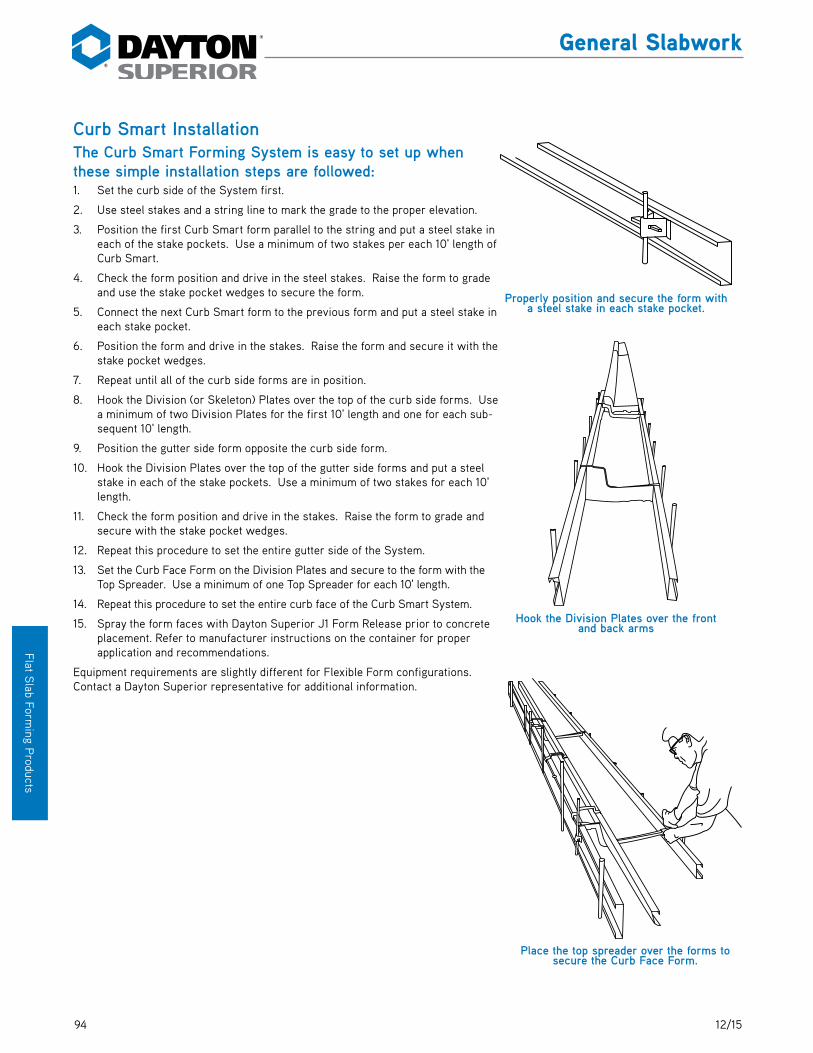
94 12/15
Flat Slab Form
ing Products
General Slabwork
Curb Smart InstallationThe Curb Smart Forming System is easy to set up when these simple installation steps are followed:1. Set the curb side of the System first.
2. Use steel stakes and a string line to mark the grade to the proper elevation.
3. Position the first Curb Smart form parallel to the string and put a steel stake in each of the stake pockets. Use a minimum of two stakes per each 10' length of Curb Smart.
4. Check the form position and drive in the steel stakes. Raise the form to grade and use the stake pocket wedges to secure the form.
5. Connect the next Curb Smart form to the previous form and put a steel stake in each stake pocket.
6. Position the form and drive in the stakes. Raise the form and secure it with the stake pocket wedges.
7. Repeat until all of the curb side forms are in position.
8. Hook the Division (or Skeleton) Plates over the top of the curb side forms. Use a minimum of two Division Plates for the first 10' length and one for each sub-sequent 10' length.
9. Position the gutter side form opposite the curb side form.
10. Hook the Division Plates over the top of the gutter side forms and put a steel stake in each of the stake pockets. Use a minimum of two stakes for each 10' length.
11. Check the form position and drive in the stakes. Raise the form to grade and secure with the stake pocket wedges.
12. Repeat this procedure to set the entire gutter side of the System.
13. Set the Curb Face Form on the Division Plates and secure to the form with the Top Spreader. Use a minimum of one Top Spreader for each 10' length.
14. Repeat this procedure to set the entire curb face of the Curb Smart System.
15. Spray the form faces with Dayton Superior J1 Form Release prior to concrete placement. Refer to manufacturer instructions on the container for proper application and recommendations.
Equipment requirements are slightly different for Flexible Form configurations. Contact a Dayton Superior representative for additional information.
Properly position and secure the form with a steel stake in each stake pocket.
Hook the Division Plates over the front and back arms
Place the top spreader over the forms to secure the Curb Face Form.
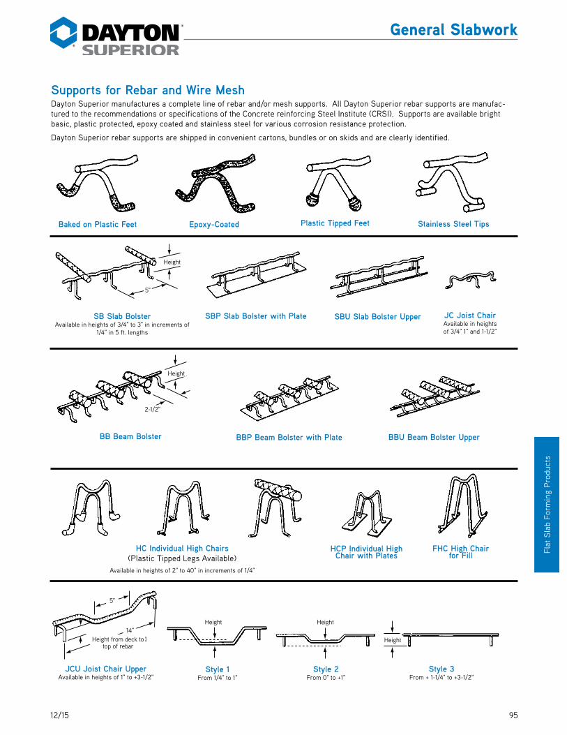
9512/15
Flat
Sla
b Fo
rmin
g P
rodu
cts
General Slabwork
Supports for Rebar and Wire MeshDayton Superior manufactures a complete line of rebar and/or mesh supports. All Dayton Superior rebar supports are manufac-tured to the recommendations or specifications of the Concrete reinforcing Steel Institute (CRSI). Supports are available bright basic, plastic protected, epoxy coated and stainless steel for various corrosion resistance protection.
Dayton Superior rebar supports are shipped in convenient cartons, bundles or on skids and are clearly identified.
14" Height (from deck �
to top of re-bar)
5"
Height Height
Height
5"
Height
2 1/2"
Height
Baked on Plastic Feet
SB Slab BolsterAvailable in heights of 3/4" to 3" in increments of
1/4" in 5 ft. lengths
JCU Joist Chair UpperAvailable in heights of 1" to +3-1/2"
Style 1From 1/4" to 1"
Style 2From 0" to +1"
Style 3From + 1-1/4" to +3-1/2"
BB Beam Bolster
JC Joist ChairAvailable in heights of 3/4" 1" and 1-1/2"
HC Individual High Chairs(Plastic Tipped Legs Available)
Available in heights of 2" to 40" in increments of 1/4"
SBP Slab Bolster with Plate
BBP Beam Bolster with Plate
HCP Individual High Chair with Plates
FHC High Chair for Fill
BBU Beam Bolster Upper
SBU Slab Bolster Upper
Epoxy-Coated Plastic Tipped Feet Stainless Steel Tips
Height
5"
Height
Height
Height
Height
Height from deck to top of rebar
2-1/2"
14"
5"

96 12/15
Flat Slab Form
ing Products
General Slabwork
BC Bar Chair BCP Bar Chair with Plate
Available in heights of 3/4" 1" and 1-1/2"
CHC Continuous High Chairs for Metal DeckingAvailable in heights of 2" to 9" with leg spacing of 4-1/2" to 10"
SLHC Straight Leg High Chair
Available in heights of 2-1/4", 2-1/2" and 2-3/4"
Rebar�CarrierRebars
Drive Rebar Support in Ground and Attach Rebar Carrier
HBC Heavy Bar ChairAvailable in heights of 3/4" 1"
and 1-1/2"
PC Precast Chair. Made from Type 430 Stainless Steel.
CHCP-Cont. High with Plate Manufactured to Order
B
C
AB
C
A
CHC Continuous High Chairs for Metal DeckingAvailable in heights of 2" to 9" with leg spacing of 4-1/2" to 10"
DC Dowel ClipAvailable for 1/2" to 1-5/8" bars
8"
Height
CHC Continuous High Chair CHCU-Cont. High Chair UpperAvailable in heights of 2" to 20" in increments of 1/4" in 5' lengths
Height
7-1/2"

9712/15
Flat
Sla
b Fo
rmin
g P
rodu
cts
General Slabwork
PBC Tower Bar Chair
PEZ E-Z Chair®PCC Castle Chair
PSP Sand Plate
PSB E-Z LOK Slab Bolster
PXC X-Chair
PLW E-Z Lok Wheel PSW Space Wheel
PTC Tower High Chair
PTCSB Tower Chair Sand Plate

98 12/15
Flat Slab Form
ing Products
General SlabworkNotes and Sketches

9912/15
Mis
cella
neou
s
Formliner MaterialsMaterials to match budget and job needs.
SPS Plastic™A polystyrene formliner for single use applications. This inexpensive option is easy to store or attach to forms, and has a quick delivery time.
ABS PlasticAn ABS formliner that provides durability and performance for 5-10 uses. This inexpensive option is easy to store or attach to forms, and has a quick delivery time.
Custom Formliners Available
Formliners

100 12/15
Miscellaneous
F56, F57, F58, F59, F60, F61 Expanded Coil InsertsDayton Superior Expanded Coil Inserts are coil or closed ferrule structural connection inserts available in two, four or six strut versions, in 3/4" through 1-1/2" diameters, with or without nailing washer.
F42 Loop Ferrule InsertDayton Superior F42 Loop Ferrule Insert is a versatile insert suited for structural connections and suspension of equipment, ceilings, piping, etc. Available in 1/4" to 1" diam-eter closed ferrules in 1/8" increments.
F44 Thin Slab Ferrule InsertDayton Superior F44 Thin Slab Ferrule Insert is used where the depth of embedment is limited. The F44 is spe-cially designed to develop good working loads in very thin concrete slabs. Available in 1/4" through 1" diameter, in 1/8" increments, closed ferrules.
F7, F7L Shelf Angle InsertDayton Superior Shelf Angle Insert is a malleable iron casting with a wedge shaped holding face that works in conjunction with a special Askew Head bolt. Available in standard and long configurations.
F54 Ductile EmbedDayton Superior F54 Ductile Embed is a structural embed available in 5/8" through 1-1/4" diameters and is available in several configurations. This is an integrally forged embed with no welds. It is designed to develop pullout and shear loads exceeding A325 bolt capacities.
F54C Nylon Rail Track InsertDayton Superior’s Rail Track Insert is an internally threaded rail track fastener for a 7/8"- 9 UNC threaded bolt. It is manufactured from a Nylon 6/6, 33% glass-filled material. The inserts may either be cast-in-place in a concrete substrate or post placed in a drilled hole using an epoxy adhesive.
Features and Benefits• Non-conductive material• Non-corrosive — will not rust• Over 3-1/2" of thread engagement for a variety of bolt lengths and/or shimming appli-
cations• Exterior wedges allow transfer of loads to adjacent concrete• Special ribs prohibit rotation• Convenient packaging of 200 pieces per box.
F54C Nylon Rail Track Insert
F54
F54 Ductile Embed
F56
Expanded Coil Inserts
F42
F42 Loop Ferrule Insert
F44
F44 Thin Slab Ferrule Insert
F7
Shelf Angle Insert
Inserts

12/15
Index
A2 ................................................................ 19A3 ................................................................. 19A4H ............................................................. 20A5................................................................. 21A6 ............................................................... 22A7 ................................................................ 22A7A ............................................................. 22A9................................................................ 23A9H ............................................................. 23A10 .............................................................. 23A16 .............................................................. 23A18 .............................................................. 23A19 .............................................................. 24A21 .............................................................. 24A21F ........................................................... 25A21X ........................................................... 25A22 ............................................................. 26A27 ............................................................. 27A27M .......................................................... 27A28 ............................................................. 27A29 ............................................................. 28A31 .............................................................. 28A40 ............................................................. 28A43 ............................................................. 28A44 ............................................................. 29A45 ............................................................. 29A46 ............................................................. 29A48 ............................................................. 30A51 .............................................................. 30A52 ............................................................. 30A54 .............................................................. 31A55 .............................................................. 31A56 .............................................................. 31A57 .............................................................. 31A58 ............................................................. 74A59 ............................................................. 74A63 ............................................................. 32A81 .............................................................. 32A82 ............................................................. 33A83 ............................................................. 33A89 ............................................................. 34A90 ............................................................. 43A93C ........................................................... 44A100 ........................................................... 45A110 ............................................................ 45ABS Plastic ............................................... 99Adjustable Coil Bolt ................................. 53Adjustable Kicker ..................................... 27All-Wire Saddle Hanger ........................... 80Anchor Bolt Sleeve .................................. 63Archi-Foam® ............................................. 99B1 ................................................................ 47B1B3 ........................................................... 48B2 ............................................................... 47
B2B3 ........................................................... 48B6 ................................................................ 49B7 ................................................................ 49B11 ............................................................... 50B12 .............................................................. 50B12A ............................................................ 51B12ANF ....................................................... 51B12AWN ...................................................... 51B13 .............................................................. 52B14 .............................................................. 52B14A ........................................................... 53B14W ........................................................... 54B15 .............................................................. 54B16 .............................................................. 54B17 .............................................................. 55B18 .............................................................. 55B20 ............................................................. 56B21 .............................................................. 56B22 ............................................................. 49B25 ...................................................... 52, 56B27 ............................................................. 57B29 ............................................................. 57B30 ............................................................. 58B31 .............................................................. 58B32 ............................................................. 59B33 ............................................................. 59B37 .............................................................. 60B39 ............................................................. 60B40 .............................................................. 61B42 .............................................................. 61B43 .............................................................. 61Bag Ties ..................................................... 72Base Tie ..................................................... 29Batter Washer ..................................... 61, 68C1B .............................................................. 77C1C .............................................................. 77C2 ................................................................ 78C3 ................................................................ 79C13 .............................................................. 79C13A ........................................................... 80C14 ............................................................... 81Cast Nut Washer ........................................ 51Channel Hanger ......................................... 81Closed Coupler ......................................... 70Coil Bolts ................................................... 52Coil Half Hanger ....................................... 79Coil Hanger Saddle Type ......................... 78Coil Loop Insert Straight ......................... 54Coil Nut ...................................................... 52Coil Rod ...................................................... 50Coils ............................................................ 49Column and Pilaster Forming
Suggestions ........................................ 42Cone Removal Wrench ............................. 28
Corner Washer .......................................... 24Curb Smart ................................................ 93Curb Smart Installation ........................... 94D1 ................................................................ 62D1J .............................................................. 63D1L .............................................................. 63D1LA ........................................................... 63D1S .............................................................. 63D2 ............................................................... 64D4 ............................................................... 65D-6 ........................................................ 57, 65D9 ................................................................ 65D9A ............................................................. 66D12 .............................................................. 66D12A ........................................................... 67D12F............................................................ 67D14 .............................................................. 67D18 ....................................................... 62, 68D21 .............................................................. 68D22 ....................................................... 61, 68D24 ............................................................. 69D25 ............................................................. 69D26 ............................................................. 69D30 ............................................................. 64D30A .......................................................... 70D32 ............................................................. 70D33 ............................................................. 70D40 .............................................................. 71D42 ............................................................. 72D46 ............................................................. 73D48 ............................................................. 73Double Flared Coil Loop Insert .............. 55Double Flared Criss Cross Coil Loop
Insert ...................................................... 59D/R® Thread Bar ....................................... 51D/R® Thread Bar She Bolt ...................... 70D/R® Thread Bar Taper Tie .................... 66D/R® Welding Flange ................................ 51Ductile Embed ......................................... 100Dura-Tex Lite® .......................................... 99Elasto-Tex® ................................................ 99Expanded Coil Inserts ............................ 100F1 ................................................................ 75F2 ................................................................ 75F7 .............................................................. 100F7L ............................................................ 100F42 ........................................................... 100F44 ........................................................... 100F54 ............................................................ 100F54C ......................................................... 100F56 ............................................................ 100F57 ............................................................ 100F58 ............................................................ 100F59 ............................................................ 100

12/15
Index
F60 ........................................................... 100F61 ............................................................ 100Fitting Up Bolt ........................................... 69Fitting Up Nut ............................................ 69Flat Tie ....................................................... 25Flat Washers ............................................. 50Footing Tie ................................................ 28Form Bracket ............................................ 85Form Clamp ............................................... 67Formliners ................................................. 99Four Strut Coil Tie ................................... 47G1 ................................................................ 83G1U ............................................................. 83G2 ............................................................... 83G2J ............................................................. 83G2S ............................................................. 84G3 ................................................................ 84G4 ............................................................... 84G4A ............................................................. 84G5 ................................................................ 85G7 ................................................................ 85G8 ................................................................ 85G11 ............................................................... 86G14 .............................................................. 86G15 .............................................................. 86G16 .............................................................. 87G27 ............................................................. 87G28 ............................................................. 87G29 ............................................................. 87G33 ............................................................. 88G34 ............................................................. 88G35 ............................................................. 88G37.............................................................. 88G60 ............................................................. 93Gang Loop Tie ........................................... 30Handle Coil Nut ......................................... 59Heavy Coil Nut ................................... 52, 56Heavy Duty Screed Chair Base .............. 87Heavy Duty Screed Holders ................... 86Heavy Duty Screed Support ................... 86Heavy Snap Tie ......................................... 20He-Bolt Anchors ....................................... 72He-Bolt Inserts ......................................... 72He-Bolts ...................................................... 71Hex Coupling Nut...................................... 65Hex Head Snap Tie .................................. 20Hook Bolts ................................................. 63How to Use Screed Key Joint ................ 89Impalement Safety Cap ........................... 73Insertion Tool ............................................ 74Inserts (Crimp) ......................................... 49Inside Tie Rod ........................................... 68Inside Tie Rods ......................................... 62Jahn® “A” Bracket .................................... 32
Jahn® “C” Bracket .................................... 33Jahn® Cornerlock ..................................... 33Jahn® Forming System ........................... 35Jahn® Scaffold Jack ................................ 34Joist Type Adjustable Screed Base ...... 83Load Key Joint .......................................... 88Loop Ferrule Insert ................................ 100Loop Panel Tie .......................................... 29Loose Plastic Cone .................................. 57Metal Rib .................................................... 45Metal Strapping ......................................... 23Methods of Screeding ............................. 82Nut Washer .......................................... 57, 65Nylon Rail Track Insert .......................... 100Omni Wedge .............................................. 23Panel Bolt .................................................. 23PC110 .......................................................... 73Pencil Rod .................................................. 67Pipe Holder................................................ 83Plastic Cap Strip....................................... 88Plastic Cone Removal Wrench ............... 54Plastic Cones ............................................. 19Plastic Setback Plug ................................. 61Plate Saddle Hanger ................................ 79Plate Tie ..................................................... 23Plylag .......................................................... 56Proper Method for Installing Load Key
Joint ........................................................ 91Rebar Clip and Form Spreader .............. 68Rock Anchor.............................................. 58Rod Clamps ............................................... 66Round Stake .............................................. 87Safety Cap ................................................. 73Scaffold Bracket Jack ............................. 43Screed Bases, Drive Type ...................... 84Screed Bases, Free Fit Type .................. 85Screed Bracket ......................................... 87Screed Chair Base for Steel Deck......... 85Screed Chair Bases ................................. 83Screed Chair Base With Sand Plate ...... 84Screed Key Joint ...................................... 88Screed Stake for Pipe ............................. 86Screw Anchor ........................................... 75Screw Anchor Bolt .................................. 75Screw-On Coil Tie.................................... 48Screw-On Plastic Cones ......................... 58She-Bolts ................................................... 64Shelf Angle Insert .................................. 100Single Flared Coil Insert ......................... 55Snaplug® ..................................................... 31Snap Tie Wrench ...................................... 28Spandrel Hook Tie.................................... 22Spandrel Plate Tie .................................... 22Spandrel Point Tie .................................... 22
Special Height Screed Base ................... 84Special U-Shaped Cradle Head.............. 83Speed Step® Bracket ............................... 45Spreader Cleats ........................................ 26SPS Plastic™ ............................................. 99Stainless Steel Snap Tie ......................... 29Stake .......................................................... 88Standard Snap Tie..................................... 19Strap Ties And Accessories ................... 24Strongback Loop Tie ................................ 32Supports for Rebar and Wire Mesh ....... 95Sure Guard® Rail Post System .............. 44Sure-Guard® Rebar Protective Cap ...... 73Sure-Lock Bracket .................................... 31Sure-Lock Strongback Bracket .............. 31Sure-Lock Tie ............................................ 31Sure Plug ................................................... 74Taper Ties .................................................. 65Thin Slab Ferrule Insert ........................ 100Threaded PullOut Tie ................................ 21Tie Wire ...................................................... 73Tightening Wrench ................................... 67Tip-To-Tip Tie ............................................ 23Toggle Tie .................................................. 60Triple Flared Coil Loop Insert ................. 61Turnbuckle Form Aligners ...................... 27Two Strut Coil Tie .................................... 47Vertical Wales for Curved Walls ............. 42Wale Bolt Assembly ................................. 54Wale Holder ............................................... 56Waler Tie .................................................... 30Water Resistant Washer .......................... 70Wedge Bolt................................................. 30Wedge Hangers ......................................... 77Weld Angle Bracket .................................. 69Welding Coil Tie ........................................ 49Wing Nut .................................................... 60Wrench Head Snap Tie Socket .............. 28Z Tie Holder .............................................. 30

Improper Use of Concrete Accessories Can Cause Severe Injury or Death
Read, understand and follow the information and instructions in this publication before using any of the Dayton Superior concrete accessories displayed herein. When in
doubt about the proper use or installation of any Dayton Superior concrete accessory, immediately contact the nearest Dayton Superior Service Center or Technical Service
Department for clarification. See back cover for your nearest location.
Safety Information
Dayton Superior products are intended for use by trained, qualified and experienced workers only. Misuse or lack of supervision and/or inspection can contribute to serious accidents or deaths. Any application other than those shown in this publication should be carefully tested before use.
The user of Dayton Superior products must evaluate the product application, determine the safe working load and control all field condi-tions to prevent applications of loads in excess of a product’s safe working load. Safety factors shown in this publication are approximate minimum values. The data used to develop safe working loads for products displayed in this publication are a combination of actual testing and/or other industry sources. Recommended safe working loads given for the products in this publication must never be exceeded.
Worn Working PartsFor safety, concrete accessories must be properly used and maintained. Concrete accessories shown in this publication may be subject
to wear, overloading, corrosion, deformation, intentional alteration and other factors that may affect the device’s performance. All reusable accessories must be inspected regularly by the user to determine if they may be used at the rated safe working load or should be removed from service. The frequency of inspections depends upon factors such as (but not limited to) the amount of use, period of service and environment. It is the responsibility of the user to schedule accessory hardware inspections for wear and remove the hard-ware from service when wear is noted.
Design ChangesDayton Superior reserves the right to change product designs, rated loads and product dimensions at any time without prior notice.
Note: See Safety Notes and Safety Factor Information.
Shop or Field ModificationWelding can compromise a product’s safe working load value and cause hazardous situations. Knowledge of materials, heat treating and welding
procedures is necessary for proper welding. Consult a local welding supply dealer for assistance in determining required welding procedures.Since Dayton Superior cannot control workmanship or conditions in which modifications are done, Dayton Superior cannot be responsible for any
product altered in the field.
InterchangeabilityMany concrete accessory products that Dayton Superior manufactures are designed as part of a system. Dayton Superior strongly dis-
courages efforts to interchange products supplied by other manufacturers with components supplied by Dayton Superior. When used properly, and in accordance with published instructions, Dayton Superior products have proven to be among the best designed and safest in the industry. Used improperly or with incompatible components supplied by other manufacturers, Dayton Superior products or systems may be rendered unsafe.
InstallationWARNING1. Dayton Superior Corporatinn products shall be installed and used only as indicated on the Dayton Superior Corporation installation
guidelines and training materials.2. Dayton Superior Corporation products must never be used for a purpose other than the purpose for which they were designed or in a
manner that exceeds specific load ratings.3. All instructions are to be completely followed to ensure proper and safe installation and performance4. Any improper misuse, misapplication, installation, or other failure to follow Dayton Superior Corporation’s instruction may cause prod-
uct malfunction, property damage, serious bodily injury and death.
THE CUSTOMER IS RESPONSIBLE FOR THE FOLLOWING:1. Conformance to all governing codes2. Use of appropriate industry standard hardware3. The integrity of structures to which the products are attached, including their capability to safely accept the loads imposed, as evalu-
ated by a qualified engineer.
SAFETY INSTRUCTIONS:All governing codes and regulations and those required by the job site must be observed. Always use appropriate safety equipment

Copyright © 2015 Dayton Superior Corporation, All Rights Reserved.
DS612/15
1125 Byers Road Miamisburg, OH 45342 937-866-0711888-977-9600
BUILDING STRENGTH™