Concrete Crusher, 48-52 Edward Street, Riverstone ... is understood that the Proposal seeks to...
29
This document has been prepared on behalf of Abode Design by: Northstar Air Quality Pty Ltd, Suite 1504, 275 Alfred Street, North Sydney, NSW 2060 www.northstarairquality.com | Tel: +61 (02) 9071 8600 Concrete Crusher, 48-52 Edward Street, Riverstone Mechanical Ventilation Assessment Addressee(s): Abode Design Report Reference: 18.1031.FR3V1 Date: 12 September 2018
Transcript of Concrete Crusher, 48-52 Edward Street, Riverstone ... is understood that the Proposal seeks to...

This document has been prepared on behalf of Abode Design by:
Northstar Air Quality Pty Ltd,Suite 1504, 275 Alfred Street, North Sydney, NSW 2060
www.northstarairquality.com | Tel: +61 (02) 9071 8600
Concrete Crusher, 48-52 Edward Street, Riverstone
Mechanical Ventilation Assessment
Addressee(s): Abode Design
Report Reference: 18.1031.FR3V1
Date: 12 September 2018

18.1031.FR3V1 Page ii
Quality ControlStudy Status Prepared Checked AuthorisedINTRODUCTION Final Northstar Air Quality GCG, MD FinalTHE PROPOSAL Final Northstar Air Quality GCG, MD FinalLEGISLATION, REGULATION AND GUIDANCE Final Northstar Air Quality GCG, MD FinalVENTILATION REQUIREMENTS Final Northstar Air Quality GCG, MD FinalCONCLUSION Final Northstar Air Quality GCG, MD Final
Report StatusNorthstar References Report Status Report Reference VersionYear Job Number (Draft: Final) (Rx) (Vx)18 1031 F R3 V1Based upon the above, the specific reference for this version of the report is: 18.1031.FR3V1
Final AuthorityThis report must by regarded as draft until the above study components have been each marked as final, and thedocument has been signed and dated below.
G Graham 12th September 2018
© Northstar Air Quality Pty Ltd 2018Copyright in the drawings, information and data recorded in this document (the information) is the property of Northstar Air Quality Pty
Ltd. This report has been prepared with the due care and attention of a suitably qualified consultant. Information is obtained from
sources believed to be reliable, but is in no way guaranteed. No guarantee of any kind is implied or possible where predictions of future
conditions are attempted. This report (including any enclosures and attachments) has been prepared for the exclusive use and benefit
of the addressee(s) and solely for the purpose for which it is provided. Unless we provide express prior written consent, no part of this
report should be reproduced, distributed or communicated to any third party. We do not accept any liability if this report is used for an
alternative purpose from which it is intended, nor to any third party in respect of this report.

18.1031.FR3V1 Page iii
Contents1. INTRODUCTION .................................................................................................................................. 7
1.1. Purpose of the Report ....................................................................................................................... 7
1.2. Scope of the Assessment .................................................................................................................. 8
2. THE PROPOSAL ................................................................................................................................... 9
2.1. Environmental Setting.......................................................................................................................9
2.2. Overview and Purpose..................................................................................................................... 10
2.3. Process Overview ............................................................................................................................... 11
2.4. Identification of Potential Emissions to Atmosphere.............................................................. 12
2.5. Environmental Controls .................................................................................................................. 13
2.5.1. Crusher Engine Emissions ................................................................................................................. 13
2.5.2. Dust Suppression ................................................................................................................................ 13
2.6. Activity Rates ..................................................................................................................................... 15
3. LEGISLATION, REGULATION AND GUIDANCE .......................................................................... 17
3.1. NSW Work Health and Safety Regulation 2017 ........................................................................ 17
3.2. Occupational Exposure Standards................................................................................................ 17
3.3. Standards for Ventilation................................................................................................................ 18
3.3.1. Air Pressure (Section 4.7)................................................................................................................... 18
3.3.2. Make-up of Exhaust Air (Section 4.8) .............................................................................................. 19
3.3.3. Exhaust Air Discharge (Section 4.9) .................................................................................................20
4. VENTILATION REQUIREMENTS.....................................................................................................23
4.1. Emission Rates ...................................................................................................................................23
4.2. Contaminant Concentrations.........................................................................................................25
4.3. Emission Characteristics ..................................................................................................................26
5. CONCLUSION.....................................................................................................................................27
6. REFERENCES.......................................................................................................................................29

18.1031.FR3V1 Page iv
Tables
Table 1 Identified potential sources of air emissions controlled by mechanical ventilation 13Table 2 Safe Work Australia workplace exposure standards for airborne contaminants 18Table 3 Estimated production activity 23Table 4 Calculated emissions of airborne contaminants – hourly maximum 24Table 5 Calculated emissions of airborne contaminants – hourly maximum (minus crusher engine
exhaust) 24Table 6 Emissions source parameters 26
Figures
Figure 1 Proposal site location 9Figure 2 Proposed site layout 10Figure 3 Mobirex components / individual plant configuration 11Figure 4 Dust suppression – misting water spray at product discharge above product stockpile 14Figure 5 Dust suppression – roof-mounted and floor-standing misting water sprays 14Figure 6 Contaminant concentrations by ventilation rate 25
Units Used in the Report
All units presented in the report follow the International System of Units (SI) conventions, unless derived from
references using non-SI units. In this report, units formed by the division of SI and non-SI units are expressedas a negative exponent, and do not use the solidus (/) symbol. For example, 50 micrograms per cubic metreis presented as 50 µg∙m-3 and not 50 µg/m3.

18.1031.FR3V1 Page v
Common AbbreviationsAbbreviation Term
AHD Australian height datum
AQIA air quality impact assessment
CO carbon monoxide
FEL front end loader
LGA Local Government Area
mg∙m-3 milligram per cubic metre of air
µg∙m-3 microgram per cubic metre of air
NO nitric oxide
NOX oxides of nitrogen
NO2 nitrogen dioxide
PM particulate matter
PM10 particulate matter with an aerodynamic diameter of 10 µm or less
PM2.5 particulate matter with an aerodynamic diameter of 2.5 µm or less
STEL short term exposure limit
TSP total suspended particulates
TWA time weighted average
VENM virgin extracted natural material
VKT vehicle kilometres travelled

18.1031.FR3V1 Page vi
Page left intentionally blank

18.1031.FR3V1 INTRODUCTION Page 7
1. INTRODUCTION
Abode Design (Abode) has engaged Northstar Air Quality Pty Ltd (Northstar) to perform a mechanicalventilation assessment for the proposed operation of a sandstone and concrete crusher, located within abuilding at 48-52 Edward Street, Riverstone, NSW (the Proposal site).
This assessment has been commissioned to support the Air Quality Impact Assessment (AQIA) (which in turnsupports an Environmental Impact Statement [EIS]) for the Proposal). The proposed development will (ifapproved, constructed and operated) receive virgin excavated natural material (principally sandstone) and asmaller volume of construction waste concrete, crush the material and export the crushed material for reusesuch as road base. For clarity the process does not include any concrete batching or product grinding /cutting plant.
1.1. Purpose of the Report
This mechanical ventilation assessment quantifies the ventilation rate which would be required to ensure thatthe risks associated with exposure to contaminants within the proposed building are appropriately managed.In turn, the calculated ventilation rate required to mitigate exposure risks within the building is used within theAQIA to determine the emission characteristics of the proposal and the subsequent impacts upon the ambientenvironment.
It is important to note that the mechanical ventilation assessment is based upon the hourly worst-case
operational profile of the proposal. Although the required ventilation rate (and emission rates calculated tooccur within the building) has been calculated based on this hourly profile, emissions calculated as part of theAQIA assume a worst-case 24-hour operational profile. This distinction is made as the occupational air qualitycriteria adopted for the purposes of this assessment can be short-term (15 minutes) and the ambient air qualitycriteria adopted in the AQIA are based on 24-hour and annual averaging periods (in respect to the identifiedpotential emissions).
Comparison of the emission rates estimated as part of this mechanical ventilation assessment with thosepresented within the AQIA should be performed with this distinction in mind.

18.1031.FR3V1 INTRODUCTION Page 8
1.2. Scope of the Assessment
The scope of work presented in this ventilation assessment has been prepared to:
· Provide a specification for the proposed mechanical ventilation system;· Evaluate the requirements for ventilation and emission control, in regard to mandatory extraction rates
and to manage exposure risks within the building;· Evaluate the requirements for ventilation and emission control, in regard to the protection of health in
the community at locations beyond the site boundary;· Provide details of any requirements and specifications for air pollution control techniques or systems;
and,· Provide details of the doors and windows, in regard to environmental mitigation measures.
Please note that this report provides a specification for the mechanical ventilation system based upon theextent of information available at the time of preparation and as presented in this report. Where suchinformation is updated or altered, the requirements for the building ventilation system should be reassessed.This document does not present a design for the specification derived, which is outside the scope of thecommissioned work.

18.1031.FR3V1 THE PROPOSAL Page 9
2. THE PROPOSAL
The following provides a description of the context, location, and scale of the proposal, provides a descriptionof the processes and phasing, and identifies the potential for emissions to air associated with the developmentphases.
2.1. Environmental Setting
The proposal site is located at 48-52 Edward Street, Riverstone, NSW. The proposal site is located within theLocal Government Area (LGA) of Blacktown. A map showing the location of the proposal site is illustrated inFigure 1. Please note that the receptors indicated are used in the air quality assessment (ref: 18.1031.FR1V1).
Figure 1 Proposal site location
Image courtesy of Google Maps
The Proposal site is situated in a semi-rural location and will be located on the corner of Edward Street and
Brisbane Road, Riverstone. The surrounding land use is predominantly industrial. The closest residential areasare approximately 400 meters (m) to the south-east, 250 m to the north-east and 830 m to the north-west ofthe Proposal site.
A full description of the sensitivity of the surrounding land, and the identification of discrete receptor locationsused in the AQIA is provided in the air quality impact assessment report (ref: 18.1031.FR1V1).

18.1031.FR3V1 THE PROPOSAL Page 10
2.2. Overview and Purpose
The Proposal seeks to gain development approval for the operation of a sandstone and concrete crushingprocess and related activities such as delivery, storage and despatch of material, to operate 24 hours a day 7days a week (24/7).
A layout of the proposal site is provided in Figure 2.
Figure 2 Proposed site layout
Source: Abode Design

18.1031.FR3V1 THE PROPOSAL Page 11
2.3. Process Overview
It is understood that the Proposal seeks to operate a concrete crusher housed within a building to be locatedat the Proposal site.
The crusher to be operated as part of the Proposal is nominally a Mobirex Kleeman Evo-Line MR 130 Z EVO,with a maximum potential feed capacity of approximately 450 tonnes per hour (t∙hr-1) of natural stone, orapproximately 240 t∙hr-1 of construction waste concrete (recycled product). The Proposal does not includeany concrete batching or product grinding / cutting.
The crusher is powered by a Tier 3/Stage IIIA diesel-fuelled engine with a maximum output of 410 kilowatts(kW). The Proposal does not include any diesel storage capacity on the Proposal site, and diesel will bedelivered by a re-fuelling truck when needed.
Uncrushed material, principally sandstone (virgin excavated natural material [VENM]) and concrete waste willbe imported to the site by truck which will deposit the material to a stockpile inside the building. The vehiclewill then be filled with crushed material from a product stockpile for export from the site.
The operational components of the crusher are broadly indicated in Figure 3, which is of a generic Mobirex
crusher:
Figure 3 Mobirex components / individual plant configuration
Source: Kleeman (undated) Mobirex Track-mounted impact crushers
The proposed activities on site include (in summary):· Unloading of uncrushed material (principally sandstone) from delivery trucks to a temporary storage
stockpile located on the inside of the building structure;· Using a diesel-fuelled front-end loader, transfer the uncrushed material to the feeding unit (the crusher
hopper);
18.1031.FR3V1 THE PROPOSAL Page 12
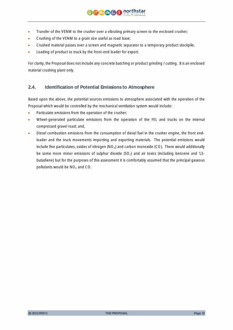
· Transfer of the VENM to the crusher over a vibrating primary screen to the enclosed crusher;· Crushing of the VENM to a grain size useful as road base;· Crushed material passes over a screen and magnetic separator to a temporary product stockpile;· Loading of product to truck by the front-end loader for export.
For clarity, the Proposal does not include any concrete batching or product grinding / cutting. It is an enclosed
material crushing plant only.
2.4. Identification of Potential Emissions to Atmosphere
Based upon the above, the potential sources emissions to atmosphere associated with the operation of theProposal which would be controlled by the mechanical ventilation system would include:· Particulate emissions from the operation of the crusher;· Wheel-generated particulate emissions from the operation of the FEL and trucks on the internal
compressed gravel road; and,· Diesel combustion emissions from the consumption of diesel fuel in the crusher engine, the front end-
loader and the truck movements importing and exporting materials. The potential emissions wouldinclude fine particulates, oxides of nitrogen (NOX) and carbon monoxide (CO). There would additionallybe some more minor emissions of sulphur dioxide (SO2) and air toxics (including benzene and 1,3-butadiene) but for the purposes of this assessment it is comfortably assumed that the principal gaseouspollutants would be NOX and CO.

18.1031.FR3V1 THE PROPOSAL Page 13
Table 1 Identified potential sources of air emissions controlled by mechanical ventilation
Source Particulate Emissions Gaseous Emissions
TSP PM10 PM2.5 NOX CO
Operational Phase
· Fugitive emissions from the crusher ü ü ü
· Wheel generated particulate – FEL ü ü ü
· Wheel generated particulate – trucks ü ü ü
· Exhaust emissions – crusher engine ü(1) ü ü ü
· Exhaust emissions – FEL engine ü(1) ü ü ü
· Exhaust emissions – truck engine ü(1) ü ü ü
Note (1) Particulate emissions from diesel combustion are predominantly less than 1 micrometre (1 μm) in diameter, and aretherefore assessed as PM2.5. As PM2.5 is essentially a subset of PM10, PM10 has been assessed at an equivalent rate to PM2.5
for the relevant sources.
2.5. Environmental Controls
2.5.1. Crusher Engine Emissions
The emissions generated from the generation of power in the crusher’s diesel-fuelled engine will be ducted
from the engine exhaust via a flexible duct to a wall-mounted discharge point, for direct emission toatmosphere. As a stationary source, the ducting removes the potential H&S impact of exposure to emissionsfrom the operation of the crusher engine in the building.
2.5.2. Dust Suppression
The crusher unit is fitted with a dust suppression system in the form of a misting water spray, located at thepoint of discharge to the product stockpile. Additional dust suppression will be provided in the form of roof-mounted misting water sprays and floor-standing directional misting water sprays. Non-Proposal relatedexamples illustrating the components of the dust suppression system are presented in Figure 4 and Figure5.
The building void will have a mechanical air extraction system, drawing the air to a dedicated roof-mounteddischarge point for dispersion to atmosphere.
The crusher will have a local exhaust ventilation extract, drawing the generated dust to a dedicated discharge
point on the building roof as described above. Secondary ventilation extraction will also occur at the crusherhopper and from the roof void.

18.1031.FR3V1 THE PROPOSAL Page 14
The diesel consumption rate at maximum throughput has been assumed to be 35 litres per hour (L∙hr-1)
Figure 4 Dust suppression – misting water spray at product discharge above product stockpile
Figure 5 Dust suppression – roof-mounted and floor-standing misting water sprays

18.1031.FR3V1 THE PROPOSAL Page 15
2.6. Activity Rates
For a full description of the proposed annual, daily and hourly maximum throughputs of the Proposal, pleaserefer to the AQIA report (18.1031.FR1V1). The information relevant to the mechanical ventilation assessment ispresented in Section 4.

18.1031.FR3V1 THE PROPOSAL Page 16
This page has been left intentionally blank

18.1031.FR3V1 LEGISLATION, REGULATION AND GUIDANCE Page 17
3. LEGISLATION, REGULATION AND GUIDANCE
3.1. NSW Work Health and Safety Regulation 2017
Chapter 3, Division 7, Clause 49 and 50 of the NSW Work Health and Safety Regulation 2017 (the Regulation)outlines the management of risks from airborne contaminants in the workplace:
49. Ensuring exposure standards for substances and mixtures not exceeded
A person conducting a business or undertaking at a workplace must ensure that no person at theworkplace is exposed to a substance or mixture in an airborne concentration that exceeds theexposure standard for the substance or mixture.
50. Monitoring airborne contaminant levels
(1) A person conducting a business or undertaking at a workplace must ensure that airmonitoring is carried out to determine the airborne concentration of a substance ormixture at the workplace to which an exposure standard applies if:
(a) the person is not certain on reasonable grounds whether or not the airborneconcentration of the substance or mixture at the workplace exceeds therelevant exposure standard, or
(b) monitoring is necessary to determine whether there is a risk to health.
(2) A person conducting a business or undertaking at a workplace must ensure that theresults of air monitoring carried out under subclause (1) are recorded, and kept for 30years after the date the record is made.
(3) A person conducting a business or undertaking at a workplace must ensure that theresults of air monitoring carried out under subclause (1) are readily accessible topersons at the workplace who may be exposed to the substance or mixture.
Penalties are in force for non-compliance with the above requirements of the Regulation.
Occupational exposure standards adopted in NSW are published in the Safe Work Australia document“Workplace Exposure Standards for Airborne Contaminants” (Safe Work Australia, 2013).
3.2. Occupational Exposure Standards
Safe Work NSW adopts the occupational exposure standards published in the Safe Work Australia document“Workplace Exposure Standards for Airborne Contaminants” (Safe Work Australia, 2013). Of relevance to thisProposal are the standards for nuisance dust (as inhalable dust), nitrogen dioxide (NO2) and carbon monoxide(CO). These standards are presented in Table 2 for both 15-minute short term exposure limits (STEL) and 8-hour time weighted averages (TWA), as appropriate.
As defined within Safe Work Australia (2013), short term exposure limit (STEL) means the time-weightedaverage maximum airborne concentration of a substance calculated over a 15-minute period. The 8-hour

18.1031.FR3V1 LEGISLATION, REGULATION AND GUIDANCE Page 18
time-weighted average (TWA) means the maximum average airborne concentration of a substance whencalculated over an eight-hour working day, for a five-day working week.
Table 2 Safe Work Australia workplace exposure standards for airborne contaminants
Pollutant Exposure limit (mg·m-3) NotesTWA STEL
Nuisance dust 10 -Page 11, Section 3.2 (j) of (Safe Work Australia, 2013)Measured as inhalable dust
Carbon monoxide 34 - Page 18 of (Safe Work Australia, 2013)
Nitrogen dioxide 5.6 9.4 Page 33 of (Safe Work Australia, 2013)
Although the exposure standards presented in Table 2 are required to be met, the Regulation also requiresrisks to health and safety be eliminated so far as is reasonably practicable. If it is not reasonably practicableto eliminate risk, it must be minimised. To comply with this duty under the Regulation, it must be ensuredthat exposure to any substance with an exposure standard is kept as low as reasonably practicable.
3.3. Standards for Ventilation
Section 3.2 outlines the exposure standards for airborne contaminants. This section addresses standardswhich are to be adopted to ensure that those standards are met, through appropriate ventilation of the facility.
Ventilation requirements for the facility are governed by the requirements of Australian Standard (AS) 1668.2-
2012 The use of ventilation and airconditioning in buildings, Part 2: Mechanical ventilation in buildings. As the
facility will be serviced by vehicles with combustion engines (trucks delivering/receiving material, front end
loader and crusher), Section 4 of AS1668.2-2012 (ventilation of enclosures used by vehicles with combustion
engines) is applicable.
Given that the ‘enclosure’ (terminology adopted in AS1668.2-2012) is not adequately described within the
Australian Standard1, compliance with Clauses 4.7, 4.8 and 4.9 is required. These requirements are
reproduced below and where reference is made to further part of the AS, these are also shown.
3.3.1. Air Pressure (Section 4.7)
4.7 Air Pressure
Air pressure in an enclosure ventilated by an exhaust air system shall comply with Clause3.7.2
1 Facility operations not described appropriately through the descriptor of car park, enclosed driveway, loading dock, automotive repairshop, vehicular lift or shaft, used by special purpose vehicles [<45kW], an enclosed queuing area or fixed staff enclosure

18.1031.FR3V1 LEGISLATION, REGULATION AND GUIDANCE Page 19
3.7.2 Air Pressures
The air pressure of enclosures served by a required general exhaust system shall be less thanthat of adjacent enclosures not served by required exhaust systems, during normal operationof the system.
NOTE: This may be evidenced by net airflow from the higher pressure to the lower pressurecombined with no significant transfer of air into the high-pressure area.
C3.7.2 Where it is expected that a negative pressure will exist in an enclosure relative tooutside, it is not recommended that open-flued gas appliances be installed.
3.3.2. Make-up of Exhaust Air (Section 4.8)
4.8 Make-up of Exhaust Air
The make-up of exhaust air shall be in accordance with Clause 3.8. Where a supplyventilation system for make-up air is provided, it shall have a flow rate of not less than 75%and not more than 90% of the exhaust airflow rate.
3.8 Replenishment of Exhaust Air
3.8.1 Source
The air exhausted from enclosures shall be replenished by outdoor air, transfer air or bymake-up air of an acceptable quality from an adjacent enclosure. Make-up air shall not bedrawn from an enclosure ventilated by a required exhaust system or from an adjacent carpark. Make-up air from an enclosure ventilated by a required exhaust system is permittedfor unoccupied enclosures. Where make-up air or transfer air is not available, a supply airventilation system shall be permitted. Where the make-up air is drawn from outside thebuilding, the intake shall comply with Clause 2.3.
2.3 Outdoor Air Intakes
2.3.1 Location
Intakes for outdoor air shall be located and arranged so that under all conditions of normaloperation –
(a) Contamination from air exhausts, cooling tower discharges, gas flues, work processesand other sources of pollution do not reduce the quality of outdoor air entering the intaketo a level significantly below that of outdoor air in the locality, except where outdoor airentering the intake is treated to achieve the same effect; and,
(b) The effects of wind, adjacent structures and other factors do not cause the flow rate ofoutdoor air to be reduced below the minimum requirements of this Section.
2.3.2 Passage of air
Outdoor air shall pass to the air-handling plant directly through a duct, plenum or plantroom connected to the intake.
Enclosures used for storage of equipment, plant or materials likely to contaminate the airshall not be used as plenums. A plant room housing equipment or materials that do notcontaminate the air may act as a plenum.
3.8.2 Amount
Where the enclosure adjacent to the exhaust enclosures (and from which make-up air is beingdrawn) is itself served by supply ventilation systems, the outdoor airflow rate to these supply

18.1031.FR3V1 LEGISLATION, REGULATION AND GUIDANCE Page 20
ventilation systems shall be increased, as necessary, to accommodate the amount of make-up air required for the exhaust ventilation system.
3.8.3 Make-up air for kitchen exhaust hoods
Not relevant
3.8.4 Pressure drop
Openings required in enclosure walls, ceilings or floors to allow passage of make-up airfrom adjacent enclosures or outside the building shall be of adequate size to ensure that thepressure drop between enclosures does not exceed 12 Pa.
C3.8.4 Where it is expected that a negative pressure will exist in an enclosure relative tooutside, it is not recommended that open-flued gas appliances be installed.
3.8.5 Electrical interlocking of exhaust and supply air
When a local exhaust system requires a mechanical supply air system to replenish exhaustair, the system shall be interlocked so that the supply system will always run when the exhaustsystem is operated.
3.3.3. Exhaust Air Discharge (Section 4.9)
4.9 Exhaust Air Discharge
Exhaust air discharge shall be in accordance with Clause 3.10.2
3.10.2 Discharges not deemed objectionable
Air discharges that are not deemed to contain objectionable effluent shall be in accordancewith the following:
(a) The discharge shall be located and arranged so that the effects of wind, adjacentstructures or other factors do not cause the airflow rates to be reduced below theminimum requirement of this Standard.
(b) The discharge shall be not less than the distances given in Table 3.4 from any outdoorair intake opening, natural ventilation device or opening.
(c) The discharge shall be emitted to the outside at velocities and in a direction that willensure, to the extent practicable, no danger to health or prevent a nuisance fromoccurring.
(d) The discharge shall not be less than the distance given in Table 3.4 from the propertyboundary, except that where the dimensions of the property make this impossible, thenthe greatest possible distance shall apply. Discharge shall be permitted on anyboundary to a public street that is wider than relevant requirements of Table 3.4,provided that the distance required by Table 3.4 from an adjacent property boundary isalso met.

18.1031.FR3V1 LEGISLATION, REGULATION AND GUIDANCE Page 21
Table 3.4 Minimum separation distances from discharges to intakes, boundary or naturalventilation device
Airflow rate within the minimum distanceL/s
Minimum distancem
<200 1 (see Note<400 2<600 3<800 4<1000 5≥1000 6
Note: For airflow rates of less than 200L/s, separation of discharge from natural ventilation openingswithin the same sole occupancy do not apply

18.1031.FR3V1 LEGISLATION, REGULATION AND GUIDANCE Page 22
This page has been left intentionally blank

18.1031.FR3V1 VENTILATION REQUIREMENTS Page 23
4. VENTILATION REQUIREMENTS
The requirements for mechanical ventilation of the Proposal site have been calculated through the assessmentof the:
· emissions anticipated to be generated by the Proposal activities; and,· ventilation rate required to ensure that those concentrations remain below the relevant criteria.
These are described further below.
4.1. Emission Rates
To meet the requirements of the mechanical ventilation assessment, the hourly worst-case emissions profileof the Proposal has been considered. In relation to the 8-hour TWA exposure limits (inhalable dust, CO andNO2), this represents a worst-case assessment as it is highly unlikely that the Proposal would operate at thosehourly maximum activity rates for a period of 8-hours. However, it represents a scenario with which tocompare against the 15-minute STEL (for NO2) which is entirely appropriate.
Presented in Table 2 are the activity rates for the Proposal adopted in the AQIA (ref 18.1031.FR1V1) and withinthis assessment.
Table 3 Estimated production activity
Activity Units Annual Daily Hourly
Crusher tonnes 90,000 10,800
(max daily capacity)
450
(max hourly capacity)
hour 8,760
(operating continuously)
24
(operating continuously)
1
(operating continuously)
FEL hour 8,760
(operating continuously)
24
(operating continuously)
1
(operating continuously)
Trucks number 2,572
(required for 90,000 tonnes)
25
(max daily delivery rate)
5
(max hourly delivery rate)
VKT 231 2.3 0.5
18.1031.FR3V1 VENTILATION REQUIREMENTS Page 24
The emissions estimation techniques used in this assessment are identical to those adopted within the AQIA.The critical assumptions of relevance to this assessment of mechanical ventilation are presented below.
· The Proposal is operational for 24 hours a day, 7 days a week;· The crusher is assumed to be operational at maximum capacity of 450 tonnes per hour over the hours
of operation (load factor of 12) consuming 35 L·hr-1 of diesel at this maximum load profile;· The front-end loader is assumed to be 100% utilised over the hours of operation (load factor of 1),
consuming 8.9 L·hr-1 of diesel at this maximum load profile;· A maximum of five trucks would visit the Proposal site per hour, delivering and receiving 175 tonnes of
material per hour over the hours of operation, each consuming 4 L·hr-1 of diesel at this load profile;· Unloading of trucks, management of the uncrushed material stockpile and loading of trucks is assumed
to operate at the activity rate of 175 tph (limited by the maximum number of vehicles per hour [five]);· Loading of the crusher, crushing, screening and loading of crushed material to the stockpile is assumed
to operate at the activity rate of 450 tph (limited by the nameplate capacity of the crusher [450 tph]);and,
· Emissions of oxides of nitrogen (NOX) are assumed to contain 10% primary NO2.
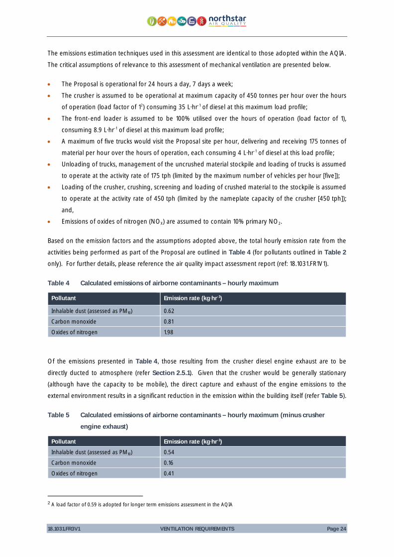
Based on the emission factors and the assumptions adopted above, the total hourly emission rate from theactivities being performed as part of the Proposal are outlined in Table 4 (for pollutants outlined in Table 2only). For further details, please reference the air quality impact assessment report (ref: 18.1031.FR1V1).
Table 4 Calculated emissions of airborne contaminants – hourly maximum
Pollutant Emission rate (kg·hr-1)
Inhalable dust (assessed as PM10) 0.62
Carbon monoxide 0.81
Oxides of nitrogen 1.98
Of the emissions presented in Table 4, those resulting from the crusher diesel engine exhaust are to be
directly ducted to atmosphere (refer Section 2.5.1). Given that the crusher would be generally stationary(although have the capacity to be mobile), the direct capture and exhaust of the engine emissions to theexternal environment results in a significant reduction in the emission within the building itself (refer Table 5).
Table 5 Calculated emissions of airborne contaminants – hourly maximum (minus crusherengine exhaust)
Pollutant Emission rate (kg·hr-1)Inhalable dust (assessed as PM10) 0.54
Carbon monoxide 0.16
Oxides of nitrogen 0.41
2 A load factor of 0.59 is adopted for longer term emissions assessment in the AQIA
18.1031.FR3V1 VENTILATION REQUIREMENTS Page 25
4.2. Contaminant Concentrations
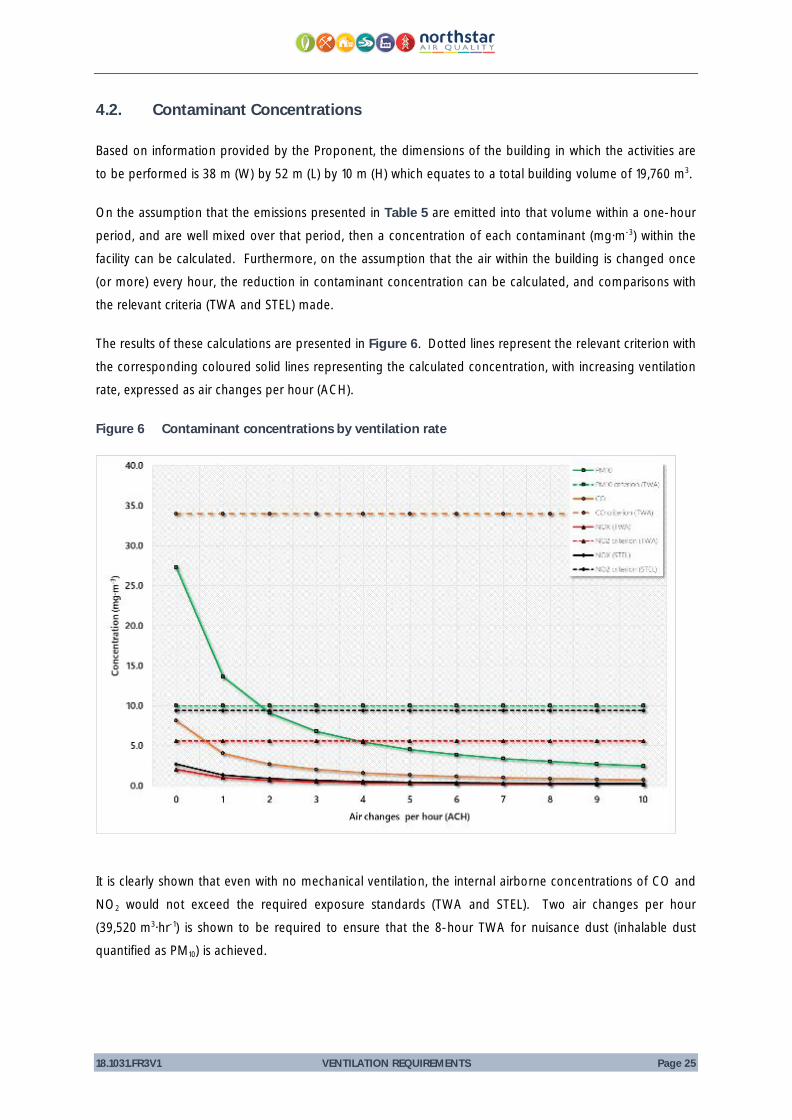
Based on information provided by the Proponent, the dimensions of the building in which the activities areto be performed is 38 m (W) by 52 m (L) by 10 m (H) which equates to a total building volume of 19,760 m3.
On the assumption that the emissions presented in Table 5 are emitted into that volume within a one-hourperiod, and are well mixed over that period, then a concentration of each contaminant (mg·m-3) within thefacility can be calculated. Furthermore, on the assumption that the air within the building is changed once(or more) every hour, the reduction in contaminant concentration can be calculated, and comparisons withthe relevant criteria (TWA and STEL) made.
The results of these calculations are presented in Figure 6. Dotted lines represent the relevant criterion withthe corresponding coloured solid lines representing the calculated concentration, with increasing ventilationrate, expressed as air changes per hour (ACH).
Figure 6 Contaminant concentrations by ventilation rate
It is clearly shown that even with no mechanical ventilation, the internal airborne concentrations of CO andNO2 would not exceed the required exposure standards (TWA and STEL). Two air changes per hour(39,520 m3·hr-1) is shown to be required to ensure that the 8-hour TWA for nuisance dust (inhalable dustquantified as PM10) is achieved.
18.1031.FR3V1 VENTILATION REQUIREMENTS Page 26
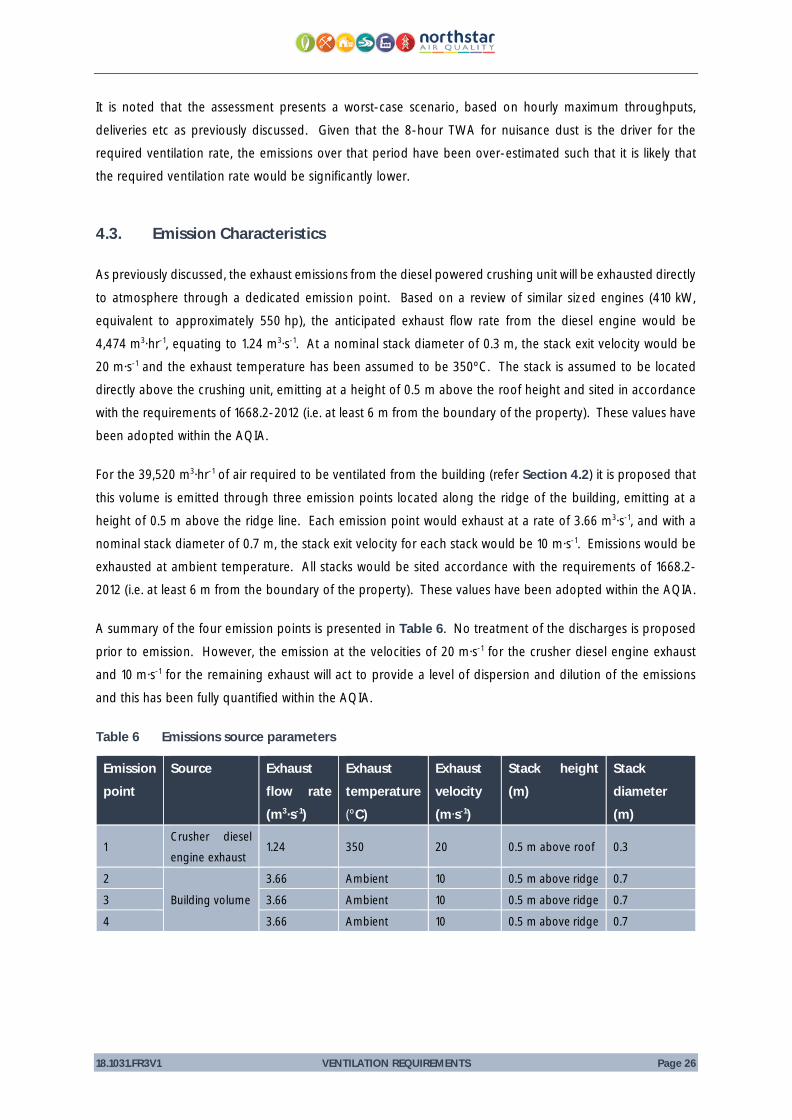
It is noted that the assessment presents a worst-case scenario, based on hourly maximum throughputs,deliveries etc as previously discussed. Given that the 8-hour TWA for nuisance dust is the driver for therequired ventilation rate, the emissions over that period have been over-estimated such that it is likely thatthe required ventilation rate would be significantly lower.
4.3. Emission Characteristics
As previously discussed, the exhaust emissions from the diesel powered crushing unit will be exhausted directly
to atmosphere through a dedicated emission point. Based on a review of similar sized engines (410 kW,equivalent to approximately 550 hp), the anticipated exhaust flow rate from the diesel engine would be4,474 m3·hr-1, equating to 1.24 m3·s-1. At a nominal stack diameter of 0.3 m, the stack exit velocity would be20 m·s-1 and the exhaust temperature has been assumed to be 350ºC. The stack is assumed to be locateddirectly above the crushing unit, emitting at a height of 0.5 m above the roof height and sited in accordancewith the requirements of 1668.2-2012 (i.e. at least 6 m from the boundary of the property). These values havebeen adopted within the AQIA.
For the 39,520 m3·hr-1 of air required to be ventilated from the building (refer Section 4.2) it is proposed that
this volume is emitted through three emission points located along the ridge of the building, emitting at aheight of 0.5 m above the ridge line. Each emission point would exhaust at a rate of 3.66 m3·s-1, and with anominal stack diameter of 0.7 m, the stack exit velocity for each stack would be 10 m·s-1. Emissions would beexhausted at ambient temperature. All stacks would be sited accordance with the requirements of 1668.2-2012 (i.e. at least 6 m from the boundary of the property). These values have been adopted within the AQIA.
A summary of the four emission points is presented in Table 6. No treatment of the discharges is proposedprior to emission. However, the emission at the velocities of 20 m·s-1 for the crusher diesel engine exhaustand 10 m·s-1 for the remaining exhaust will act to provide a level of dispersion and dilution of the emissionsand this has been fully quantified within the AQIA.
Table 6 Emissions source parameters
Emissionpoint
Source Exhaustflow rate(m3·s-1)
Exhausttemperature(ºC)
Exhaustvelocity(m·s-1)
Stack height(m)
Stackdiameter(m)
1Crusher dieselengine exhaust
1.24 350 20 0.5 m above roof 0.3
2
Building volume
3.66 Ambient 10 0.5 m above ridge 0.7
3 3.66 Ambient 10 0.5 m above ridge 0.7
4 3.66 Ambient 10 0.5 m above ridge 0.7

18.1031.FR3V1 CONCLUSION Page 27
5. CONCLUSION
For the purposes of the Proposal, ventilation control through a pressure differential will be maintained throughthe use of exhaust ventilation which would act to ensure net airflow into the building. Although a negativepressure environment is not proposed (and not considered to be required, given the level of activities beingperformed, and the dust suppression being proposed), roller doors would be closed at all times when novehicles are entering or leaving the facility.
Air exhausted from the facility will be replenished by outdoor air. The intakes for outdoor air will be located
away from sources of emissions and pollutant-generating sources as far as practicable and away fromstructures which would reduce the flow rate of air into the facility. The intakes would be appropriately sizedto ensure that the pressure drop between the internal and external environment does not exceed 12 pascals(Pa).
Outdoor air would be drawn into the building, and extracted through the ductwork installed as local exhaustventilation and through a number of stacks on the roof of the facility.
The air discharges from the facility will be designed in accordance with the standard, and will be located atleast 6 m from the boundary of the property, outdoor air intakes or natural ventilation devices or openings.
As outlined in Section 4.3, the calculated flow rate required to meet occupational exposure standards is39,520 m3∙hr-1, equivalent to two air changes per hour (2 ACH). This is proposed to be split between threedischarge points. An additional discharge point is proposed which would service only the exhaust from thecrusher diesel engine.

18.1031.FR3V1 CONCLUSION Page 28
This page has been left intentionally blank

18.1031.FR3V1 REFERENCES Page 29
6. REFERENCES
NSW Government. (2017). Work Health and Safety Regulation 2017.
Safe Work Australia. (2013). Workplace Exposure Standards for Airborne Contaminants.
Standards Australia. (2012). AS 1668.2-2012 The use of ventilation and airconditioning in building,
Part 2: mechanical ventilation in buildings.
![LOESCHE Selective comminution of concrete waste … comminution of concrete waste ... the jaw crusher process [11] ... cess technology and mechanical equipment that is](https://static.fdocuments.us/doc/165x107/5ae056b17f8b9afd1a8dd243/loesche-selective-comminution-of-concrete-waste-comminution-of-concrete-waste.jpg)