Conclusions of phase 1 & transition to phase 2 of MultiPinch Franco Alladio Luca Boncagni, Andrea...
25
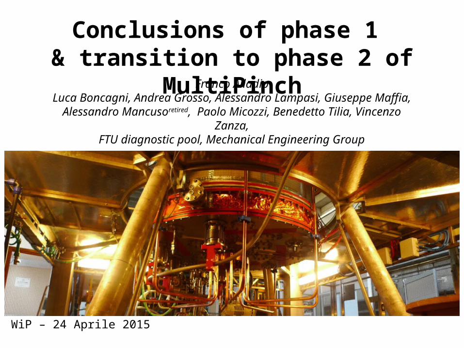
Conclusions of phase 1 & transition to phase 2 of MultiPinch Franco Alladio Luca Boncagni, Andrea Grosso, Alessandro Lampasi, Giuseppe Maffia, Alessandro Mancuso retired , Paolo Micozzi, Benedetto Tilia, Vincenzo Zanza, FTU diagnostic pool, Mechanical Engineering Group WiP – 24 Aprile 2015
-
Upload
christian-knight -
Category
Documents
-
view
215 -
download
0
Transcript of Conclusions of phase 1 & transition to phase 2 of MultiPinch Franco Alladio Luca Boncagni, Andrea...
Conclusions of phase 1 & transition to phase 2 of MultiPinch
Franco AlladioLuca Boncagni, Andrea Grosso, Alessandro Lampasi, Giuseppe Maffia,
Alessandro Mancusoretired, Paolo Micozzi, Benedetto Tilia, Vincenzo Zanza,FTU diagnostic pool, Mechanical Engineering Group
WiP – 24 Aprile 2015

PROTO-SPHERA immediate aimA spherical tokamak where the metal centerpost is replaced by a plasma centerpost:
will the plasma centerpost be able to produce and drive the plasma ring?
anode and cathode needed for setting up the configuration
Introduction

A simply connected configuration particularly suitable for magnetic fusion space propulsion:charged fusion products would emerge in jets through triple X-point: high efficiency for thrust
Sidney ICPP 2001orbits of promptly lost
charged fusion products
Possible far-future aim…Introduction
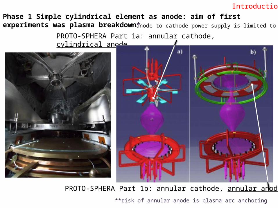
PROTO-SPHERA Part 1b: annular cathode, annular anode**
PROTO-SPHERA Part 1a: annular cathode, cylindrical anode
Phase 1 Simple cylindrical element as anode: aim of first experiments was plasma breakdown*
**risk of annular anode is plasma arc anchoring
Introduction
* anode to cathode power supply is limited to 350 V
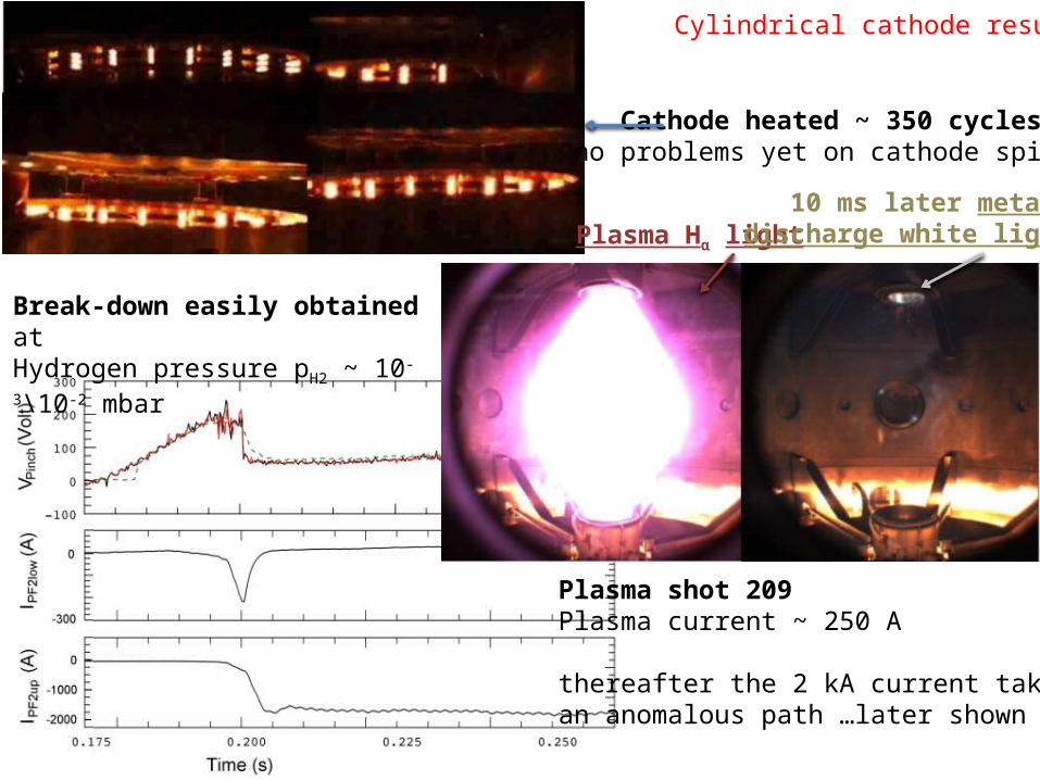
Cathode heated ~ 350 cycles:no problems yet on cathode spirals
Plasma shot 209 Plasma current ~ 250 A
thereafter the 2 kA current takes an anomalous path …later shown
Plasma Hα light10 ms later metal
discharge white light
Cylindrical cathode results
Break-down easily obtained at Hydrogen pressure pH2 ~ 10-3\10-2 mbar

First problem caused by cylindrical anode:improper back discharge from the cylindrical anodedue to field configuration in upper part of the machine:
the plasma searches the not-yet-in place annular anode
Plasma shot 170, anode camera
Cylindrical cathode results

magnetic field configuration was modified in the upper part of the machine…
…but discharges could appear from cylindricalanode to busbar entrances on top of machine
Plasma shot 216, anode camera
Second problem caused by cylindrical anode:
Cylindrical cathode results
Busbarentrance

Vanode ~ +100 V
Vcathode ~ -100 V
VPF4low ~ -50 V
VPF2-3low ~ 0 V
VPF4up ~ +70 V
VPF2-3up ~ +30 V
Vvessel = 0 V (ground)
Plasma shot 170, voltages of floating PF coils casings (plasma double layers)
Conducting vessel at ground, PF coil casings insulated from vessel, anode and cathode…a gradual increase of the floating voltages from cathode to anode along the height
Cylindrical cathode results

Vanode ~ +100 V
Vcathode ~ -100 V
VPF4low ~ -50 V
VPF2-3low ~ +50V
VPF4up ~ +30 V
VPF2-3up ~ +70 V
Vvessel =0 V (ground)
Plasma shot 228, use of lower PF2-3 as a “triode grid”
Lower PF2-3 coils casing connected with 10 Ω to the anode (Vincenzo Zanza proposal)…sharper increase of the floating voltages from cathode to anode near the cathode
Cylindrical cathode results

Plasma shot 228
Plasma breakdown 10 ms later, 500 A 20 ms later, 1500 A
Anode camera
Plasma camera
Cathode camera
Cylindrical cathode results
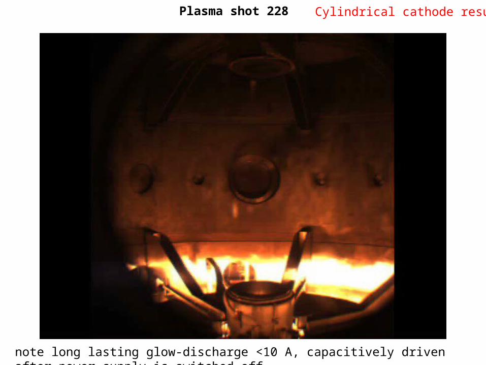
Plasma shot 228 Cylindrical cathode results
note long lasting glow-discharge <10 A, capacitively driven after power supply is switched-off

Third problem caused by cylindrical anode:
Plasma starts on its proper path,through both PF2 throttles
then a metal dischargeappears between thecylindrical anode and itscontaining PF2 upper coil casing
The cylindrical gap between the throttle of the PF2 upper coil casing and the cylindrical anode is very small (~ 5 mm): at any machine closing the upper lid had to be finely aligned in order to avoid a short circuit between the two
PF2
Anode
Cylindrical cathode results
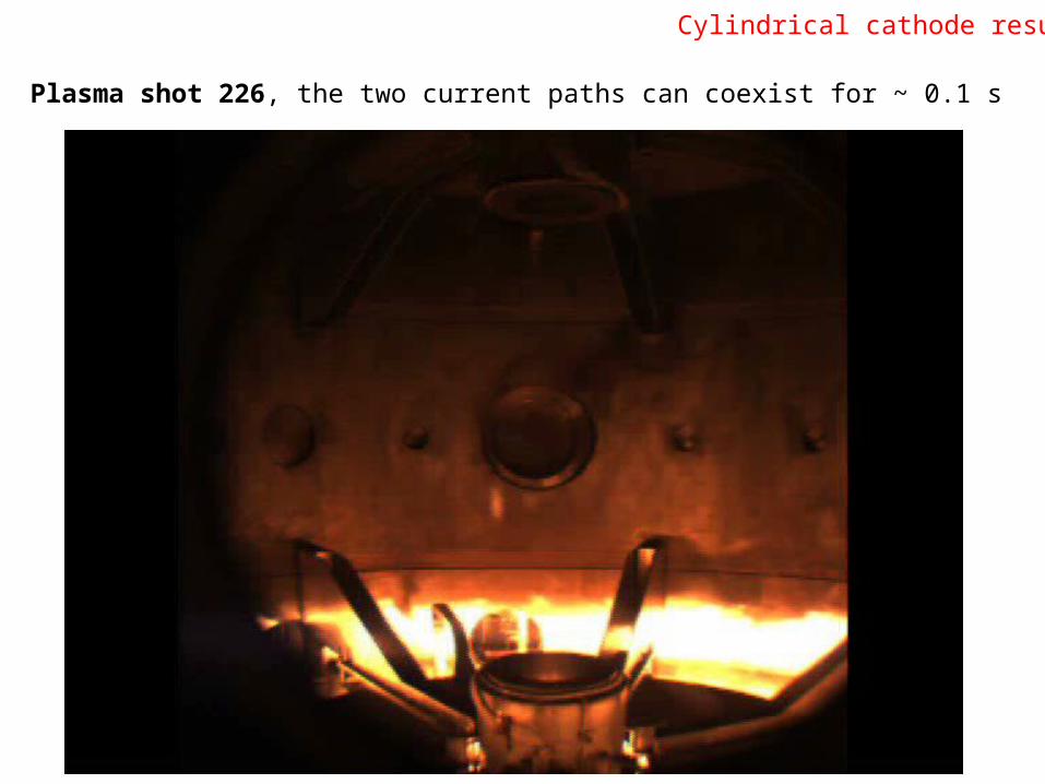
Plasma shot 226, the two current paths can coexist for ~ 0.1 s
Cylindrical cathode results

Anomalous current path from 1) cylindrical anode to PF22) PF2 to the 6 vessel supports3) along vessel4) vessel to back of cathode
plasma discharge from front of cathode is replaced by plasma discharge from back of cathode
1
2
3
4
2

Problems with electrical power supply:
No major problem up to now, controls of normal and anomalous situations (protections)work smoothly
Only a plastic lever broke with no reason (poor plastic quality) in an ABB disconnecting switch, a few €cents car fuse and the clever hand of Giuseppe Maffia cured it…
Minor problems after a protection intervention …the next shot (only) starts at wrong time
…but it is not conceivable to carry on working without a maintenance contract withEEI producer, any problem would result in 6-12 month delay to experiments…
…Cost of contract ~ 15 k€
A reasonable management of the machine would require this contract in operation6 month from now (autumn 2015)
Cylindrical cathode results

Damages to anode busbars
damages to anode busbars have been cured
top lid of the machine routinely removed, supports for top lid built by Mech.Eng. Group
Cylindrical cathode results

…but damages to cathode busbars
…however damages to cathode busbars cannot be cured, the tools for opening the lower lid of the machine have been designed but not yet built
A reasonable management of the machine would require these tools to be ready 6 month from now (autumn 2015)
Phase-2 restart will have to operate with grounded cathode, as the resistance between cathode and vessel has dropped at the end of phase-1 at a few tens of Ω…
Cathode filaments look brand new…
Cylindrical cathode results

Conclusions of cylindrical anode operation:1) Plasma breakdown has been achieved at ~ 170-200 V (maximum available voltage 350 V)2) Successive problems (plasma current & duration) arise from cylindrical provisional cathode
Decisions:3) Install final annular anode2) Allow connections of vessel to PF coils casings down to “0 Ω resistance”
Fight with real problems relevant to PROTO-SPHERA and not with provisional problems…
Annular anode as pre-mounted in ASG (Genua)
Aim of MultiPinch with annular anode:
Plasma discharges up to 8.5 kA
lasting a few 100s ms
Annular anode restart

Tools for opening the lower lid of the machinedesigned by Alessandro Mancusoand Paolo Rossi
Annular anode restart

Vanode ~ +200 V
Vcathode ~ 0 V (ground)
VPF4low +50 V
VPF2-3low ~ +70V
VPF4up ~ +100 V
VPF2-3up ~ +100 V
Vvessel =0 V (ground)
Plasma shot 209 (with cathode common set to ground)
Luckily enough the operation with the cathode set to ground has been as successfulas the operation with the cathode floating, so the phase-2 restart will have grounded cathode
1) Grounded cathode operationFurther possible problems and their cure

Plasma shot 228
X-point
2) Detrimental X-point effect?Further possible problems and their cure

the external PF coils would also eliminate the detrimental X-point effect
4 additional external PF coils(Paolo Micozzi proposal)
If in presence of the annular anode, the lines of force have to be removed from the cylindricalpart of the conducting vessel & to be concentrated on the lids, which will have to be insulated:
it would be simple to add 4 external PF coils (home-made from spare connection cables)…and to feed them in series with the internal PF coils
(PF coils power supply is more than sufficient)

3) Parasitic plasma path, outside PF2 throttles
Plasma shot 148, An earlier discharge showing parasitic plasma path on the outside, along vacuum vessel
Proposed cure for parasitic current path:build & install divertor supports … only after assessment of potentials has been obtained!
Inox divertor supports
Further possible problems and their cure
Plasma Hα light

Plasma shot 221, occurrences of anchoring: …but rotating cathode field rotates hotspots
Resolution of present camera (10 ms per frame) not sufficientin future we shall have to borrow FTU fast camera when operating
4) Arc anchoringFurther possible problems and their cure

Conclusions:
Cylindrical anode results:• Break-down obtained at Hydrogen pressure pH2 ~ 10-3\10-2 mbar, 170-200 V required• Plasma starts on proper path –through PF2 throttles• Reasonable distribution of double layer potentials on floating PF coil cases• Problems specific of cylindrical anode limit plasma current to 1.5 kA & duration to 20 ms
•• Improper back discharges from cylindrical anode if magnetic field was unmodified•• Anode busbar discharges if magnetic field was modified•• Proper plasma discharge terminated by discharge from anode to PF2 (5 mm gap!)
• Preliminary control of double layer potentials on floating PF coil casing quite helpful• No major problem on power supply (work properly in normal and protection cases)• Anode busbar damages can be cured (top lid of machine removed, supports in place)• Cathode busbar damages cannot be cured, as tools for bottom lid removal not yet built
Fight with real problems relevant to PROTO-SPHERA and not with provisional problems…Annular anode is being installed for restart of experiments, aim 8.5 kA, duration 100’s ms:• Allow control of double layer potentials on floating PF coil casings down to “0 Ω resistance”• Maintenance contract with power supply producer (EEI)• Build tools for bottom lid removal• Grounded cathode operation is mandatory, til bottom lid removal tools allow busbar cure• Detrimental X-point effect\Shaping of magnetic field could require 4 external PF coils• Parasitic plasma path (outside PF2 throttles) could require Inox divertor supports