
Conceptual Modeling (CM) for Military Modeling and Simulation (M&S)

1 Yourfilename.ppt
Date: 10/22/07
Presented by:Charles Derrick
Aviation and Missile Research, Development and Engineering Center
A View of Simulation Conceptual ModelingA View of Simulation Conceptual Modeling
Approved for public release; distribution is unlimited
2 Yourfilename.ppt
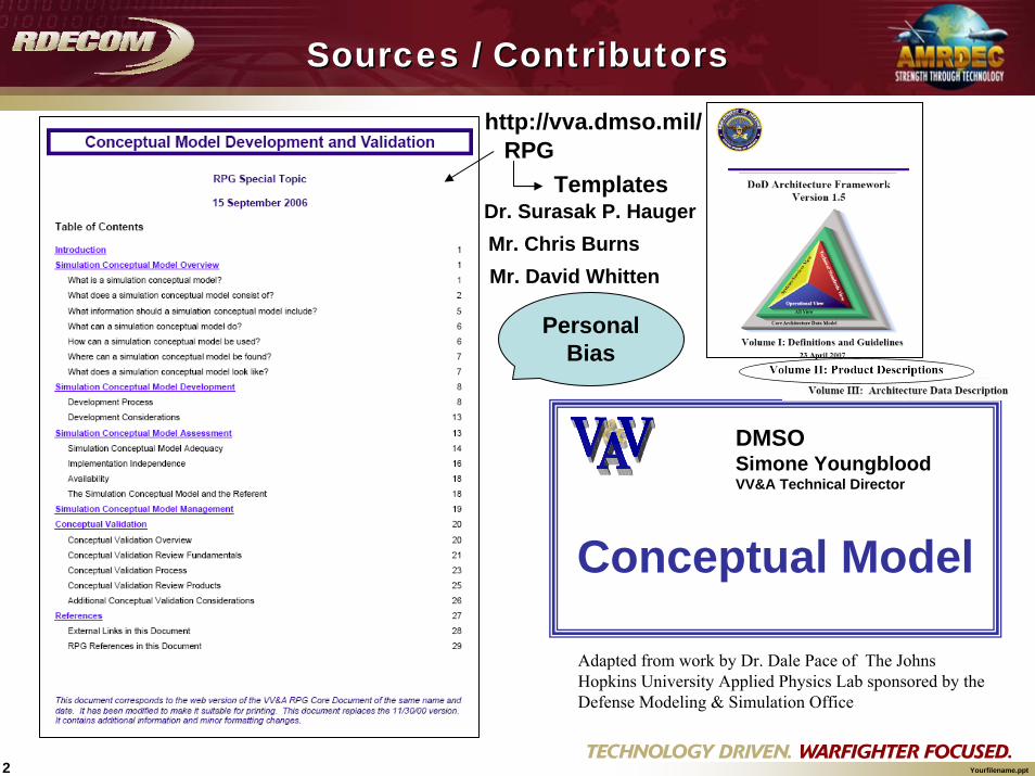
Conceptual Model
Adapted from work by Dr. Dale Pace of The Johns Hopkins University Applied Physics Lab sponsored by the Defense Modeling & Simulation Office
Personal Bias
DMSOSimone YoungbloodVV&A Technical Director
Sources / ContributorsSources / Contributors
http://vva.dmso.mil/
TemplatesRPG
Dr. Surasak P. HaugerMr. Chris BurnsMr. David Whitten
3 Yourfilename.ppt
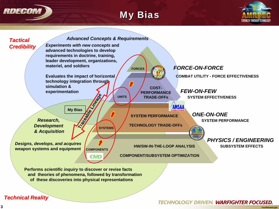
Experiments with new concepts and advanced technologies to develop requirements in doctrine, training, leader development, organizations, materiel, and soldiers
Evaluates the impact of horizontal technology integration through simulation & experimentation
Designs, develops, and acquiresweapon systems and equipment
Performs scientific inquiry to discover or revise facts and theories of phenomena, followed by transformation of these discoveries into physical representations
Research, Development & Acquisition
Advanced Concepts & Requirements
COMPONENTS
SYSTEM PERFORMANCE
SUBSYSTEM EFFECTS
COST-PERFORMANCE
TRADE-OFFs
SYSTEM PERFORMANCETECHNOLOGY TRADE-OFFs
COMPONENT/SUBSYSTEM OPTIMIZATION
HW/SW-IN-THE-LOOP ANALYSISPHYSICS / ENGINEERING
ONE-ON-ONE
FEW-ON-FEW
FORCE-ON-FORCE
SYSTEMS
UNITS
FORCES
SYSTEM EFFECTIVENESS
COMBAT UTILITY - FORCE EFFECTIVENESSTr
acea
ble
Line
age
Tactical Tactical CredibilityCredibility
Technical RealityTechnical Reality
My Bias
My BiasMy Bias

4 Yourfilename.ppt
IDEEAS Analysis ProcessIDEEAS Analysis Process
Model Development and Analysis:Acts as subject matter experts to create appropriate representations of systems and analyze results.
Software Development:
Modify current parameters used in models & develop new code when needed.
Operations Research:Design experiments, determines vignettes, and statistically analyzes results.
Customer:Provides input to teams and reviews prototypes to assure problem representations and study output are correct.
STUDY
Operationally Relevant? Achievable? Comparable? Measurable? Document.

5 Yourfilename.ppt
Definition used by Simone Youngblood in her class at UAH
Definition used by Simone Youngblood in her class at UAH
“The conceptual model is a simulation developer’s way of translating modeling requirements into a detailed design framework, from which the software, hardware, networks, and systems/equipment that will make up the simulation can be built, modified, or assembled.”
from SIW Paper 00F-SIW-019, “Simulation Conceptual ModelDevelopment Issues and Implications for Reuse of Simulation Components” by Dr. Dale Pace
6 Yourfilename.ppt
Online M&S Glossary(DoD 5000.59-M)
Online M&S Glossary(DoD 5000.59-M)
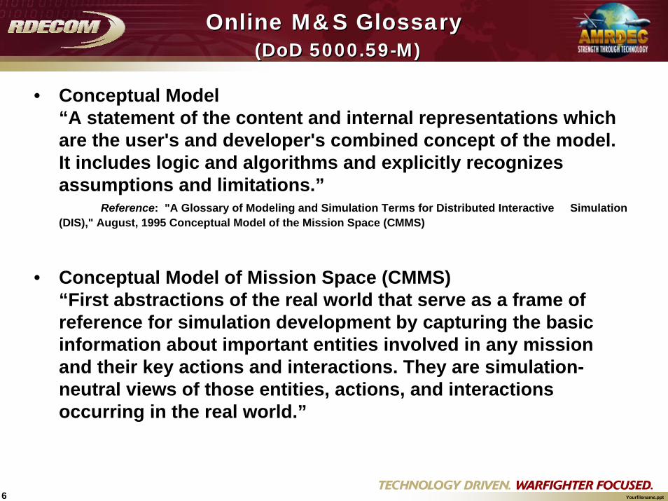
• Conceptual Model“A statement of the content and internal representations which are the user's and developer's combined concept of the model. It includes logic and algorithms and explicitly recognizes assumptions and limitations.”
Reference: "A Glossary of Modeling and Simulation Terms for Distributed Interactive Simulation (DIS)," August, 1995 Conceptual Model of the Mission Space (CMMS)
• Conceptual Model of Mission Space (CMMS)“First abstractions of the real world that serve as a frame of reference for simulation development by capturing the basic information about important entities involved in any mission and their key actions and interactions. They are simulation-neutral views of those entities, actions, and interactions occurring in the real world.”

7 Yourfilename.ppt
From: Conceptual Model Development and ValidationRPG Special Topic15 September 2006
8 Yourfilename.ppt
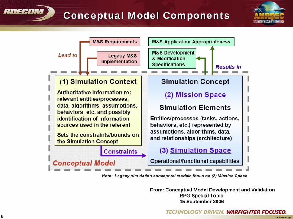
Conceptual Model ComponentsConceptual Model Components
From: Conceptual Model Development and ValidationRPG Special Topic15 September 2006

9 Yourfilename.ppt
Steps in ConceptualDevelopment
Steps in ConceptualDevelopment
Step 1: collect authoritative simulation context info
Step 2: identify entities and processes for representation
Step 3: develop simulation elements
Step 4: address relationships among simulation elements
I t e
r a t e
Adapted from work by Dr. Dale Pace, sponsored by DMSOand briefed by Simone Youngblood in her UAH Class

10 Yourfilename.ppt
• Conceptual Model Portion Identification• Principal Simulation Developer POCs• Requirements and Purpose• Overview• General Assumptions• Identification of Possible States, Tasks, Actions, and
Behaviors, Relationships and Interactions, Events, and Parameters and Factors for Entities and Processes being described
• Identification of Algorithms• Simulation Development Plans• Summary and Synopsis
Conceptual ModelDocumentation
Conceptual ModelDocumentation
Adapted from work by Dr. Dale Pace, sponsored by DMSOand briefed by Simone Youngblood in her UAH Class

11 Yourfilename.ppt
• I hope the following facilitates discussion on the application of conceptual modeling.
• These slides represent some “real-life” examples of our view in our application of conceptual modeling.
• Comments between the audience is encouraged.• Non-attribution.
Examples?Examples?

12 Yourfilename.ppt
A Specific View of Conceptual Modeling
A Specific View of Conceptual Modeling
The three simple questions asked by Chris Burns to our team at the beginning of each effort:
“What are we modeling?”“What is the purpose of the conceptual model?”“Who is the target audience?”
Chris Burns is the lead computer scientist for IDEEAS –an engagement level constructive simulation

13 Yourfilename.ppt
Our use of Conceptual Models?Our use of Conceptual Models?
• The type of model created is driven by what you are modeling– More information is required when complex specifics are involved– Software models are not sufficiently able to convey engineering details that are
not directly related to the software design.• Our Team uses:
– System Architecture Conceptual Models• Domain description, components, and the communication flow• Purpose: Define the components involved and their
intercommunication • Audience: Integrators, Network Engineers, Developers, Users
– Physics/Engineering Conceptual Models• Inputs, outputs, algorithms• Purpose: Defines the mathematical representation of a system,
including the inputs, algorithms, and outputs • Audience: Physicists, Engineers to Software Developers
– Software Conceptual Models• Software centric design representation of the system• Purpose: Representation of the system from a software centric
view, to convey operation, assumptions, and limitations• Audience: Software Developers to Physicists, Engineers

14 Yourfilename.ppt
Radar Modeling for Analysis Radar Modeling for Analysis Utilizing IDEEASUtilizing IDEEAS
Surasak P. Hauger, Ph.D.
Science Applications International Corporation (SAIC)Huntsville, AL 35805, USA
An ExampleAn Example

15 Yourfilename.ppt
Presenting the process of radar modeling for analysis by utilizing the Interactive Distributed Engineering Evaluation and Analysis Simulation (IDEEAS).
Batteries
LCMR
TPQ-37

16 Yourfilename.ppt
RADAR RAdio Detection and Ranging
Transmitter
Receiver
Target detection and information extraction
Transmitted signal
Target
Antenna
Echo signal
Basic Principle of Radar
Image derived from “Introduction to Radar Systems” by M. I. Skolnik.
Range to target
17 Yourfilename.ppt
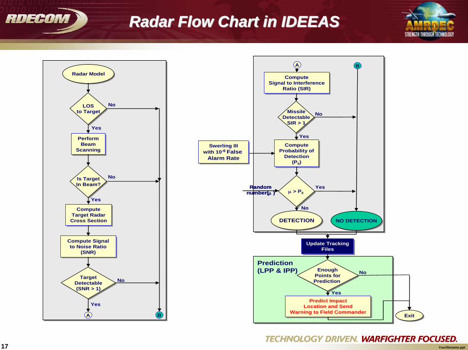
Radar Flow Chart in IDEEASRadar Flow Chart in IDEEAS
Radar ModelRadar Model
LOSto Target
LOSto Target
Is TargetIn Beam?Is TargetIn Beam?
TargetDetectable(SNR > 1)
TargetDetectable(SNR > 1)
PerformBeam
Scanning
PerformBeam
Scanning
ComputeTarget RadarCross Section
ComputeTarget RadarCross Section
Compute Signal to Noise Ratio
(SNR)
Compute Signal to Noise Ratio
(SNR)
A B
No
No
No
Yes
Yes
Yes
MissileDetectable
SIR > 1
MissileDetectable
SIR > 1
DETECTIONDETECTION
ComputeProbability of
Detection(P0)
ComputeProbability of
Detection(P0)
Update TrackingFiles
Update TrackingFiles
ExitExit
A B
ComputeSignal to Interference
Ratio (SIR)
ComputeSignal to Interference
Ratio (SIR)
μ > P0μ > P0Random
number(μ )Random
number(μ )
NO DETECTIONNO DETECTION
EnoughPoints forPrediction
EnoughPoints forPrediction
Predict ImpactLocation and Send
Warning to Field Commander
Predict ImpactLocation and Send
Warning to Field Commander
No
Yes
Yes
No
Prediction(LPP & IPP) No
Yes
Swerling IIIwith 10-6 False
Alarm Rate
Swerling IIIwith 10-6 False
Alarm Rate

18 Yourfilename.ppt
Phased Array Radar with fixed antenna panel where beams are moved electronically in any direction within a scanning limit
Mechanical Scanning Radar with rotating antenna panel
Beam ScanningBeam Scanning
19 Yourfilename.ppt
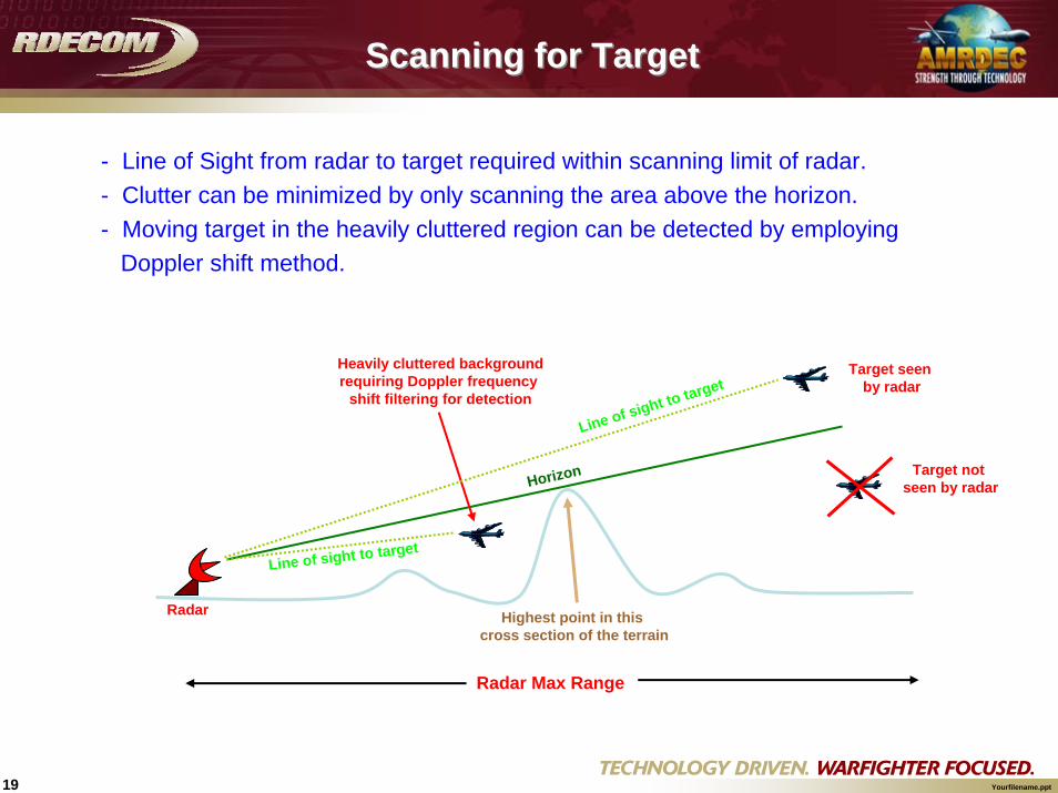
Scanning for TargetScanning for Target
- Line of Sight from radar to target required within scanning limit of radar. - Clutter can be minimized by only scanning the area above the horizon.- Moving target in the heavily cluttered region can be detected by employing
Doppler shift method.
Radar Max Range
Highest point in this cross section of the terrain
Target not seen by radar
Target seen by radar
Heavily cluttered backgroundrequiring Doppler frequency
shift filtering for detection
Horizon
Radar
Line of sight to target
Line of sight to target

20 Yourfilename.ppt
- Radar Cross Section (RCS) is the property of a scattering object that represents the magnitude of the echo signal returned to the radar by the target
- Unit of RCS is m2 or dBsm
- Even though its unit is m2, the RCS may or may not correlate with the physical size or effective area of the object
Radar Cross Section
21 Yourfilename.ppt
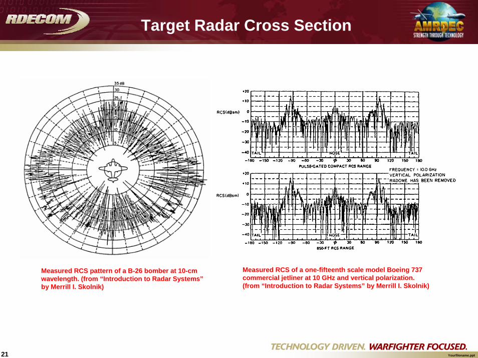
Target Radar Cross Section
Measured RCS of a one-fifteenth scale model Boeing 737 commercial jetliner at 10 GHz and vertical polarization. (from “Introduction to Radar Systems” by Merrill I. Skolnik)
Measured RCS pattern of a B-26 bomber at 10-cm wavelength. (from “Introduction to Radar Systems”by Merrill I. Skolnik)
22 Yourfilename.ppt
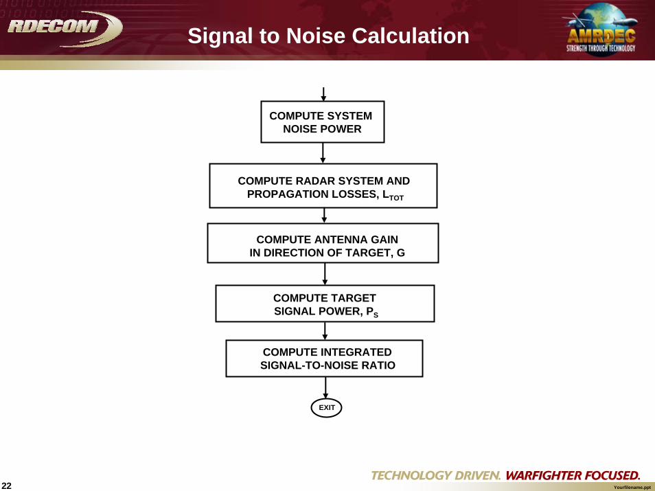
COMPUTE SYSTEM NOISE POWER
COMPUTE RADAR SYSTEM AND PROPAGATION LOSSES, LTOT
COMPUTE ANTENNA GAIN IN DIRECTION OF TARGET, G
COMPUTE TARGET SIGNAL POWER, PS
COMPUTE INTEGRATED SIGNAL-TO-NOISE RATIO
EXIT
Signal to Noise Calculation

23 Yourfilename.ppt
τFo
nNkTP =
Pn = Radar System noise powerk = Boltzmann's constantTo = System reference noise temperature (°K)NF = Receiver noise figureτ = Radar pulse width
Noise Signal Level
24 Yourfilename.ppt
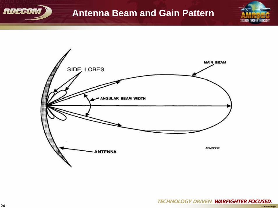
Antenna Beam and Gain Pattern

25 Yourfilename.ppt
Example of 3-D Antenna Pattern(from “Radar Handbook” edited by Merrill I. Skolnik)

26 Yourfilename.ppt
Antenna Gain in the Direction of TargetAntenna Gain in the Direction of Target
Beam Boresight (Look Angle)
Antenna Gain Pattern
TargetTarget Antenna Gain Target angle
Antenna gain representation within IDEEAS (note pattern characteristic is configurable
through input)
27 Yourfilename.ppt
43
22
)4( LRGPP T
s πσλ
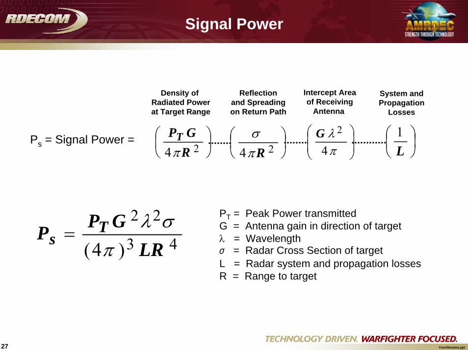
=PT = Peak Power transmittedG = Antenna gain in direction of targetλ = Wavelengthσ = Radar Cross Section of targetL = Radar system and propagation lossesR = Range to target
Ps = Signal Power = ⎟⎠⎞
⎜⎝⎛
24 RGPT
π⎟⎠⎞
⎜⎝⎛
24 Rπσ
⎟⎟⎠
⎞⎜⎜⎝
⎛
πλ
4
2G⎟⎠⎞
⎜⎝⎛
L1
Density of Radiated Powerat Target Range
Intercept Areaof Receiving
Antenna
Reflection and Spreading on Return Path
System andPropagation
Losses
Signal Power

28 Yourfilename.ppt
⎟⎟⎠
⎞⎜⎜⎝
⎛=
N
S
PP
GINTSNR
Compute Integration GainCompute Integration Gain
Dwell – The time on target, and time it takes to scan the antenna beam over a beamwidth or some fraction of a beamwidth
Duty Cycle – A measure of the fraction of the time a radar is transmitting
Number of pulses during dwell time = Dwell×PRF Integration Gain
Leading to:

29 Yourfilename.ppt
4 3
2
)4(
LRNkT
GGPSNR
F
rpwtpk
O
pulsesNπ
λστ=
Signal to Noise Ratio
43
2
)()4(
SNRLNkT
GGPR
F
rpwtpk
O
pulsesNπ
λστ=
Radar Range Equation

30 Yourfilename.ppt
Pulse Compression Simplified Concept
Image from Radar Pulse Compression by Chris Allen, June 17, 2004.
31 Yourfilename.ppt
Puls
e C
ompr
essi
onDwell
Pulse #1 Pulse #N Pulse #N+1
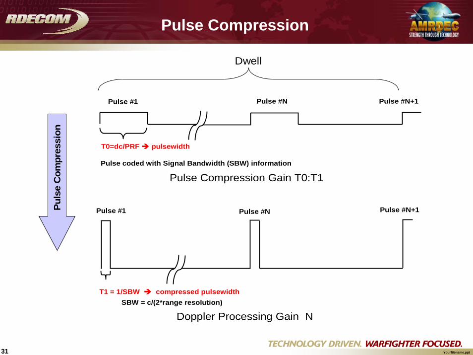
Pulse Compression Gain T0:T1
T0=dc/PRF pulsewidth
Pulse coded with Signal Bandwidth (SBW) information
Pulse #1 Pulse #N Pulse #N+1
T1 = 1/SBW compressed pulsewidthSBW = c/(2*range resolution)
Doppler Processing Gain N
Pulse Compression

32 Yourfilename.ppt
Signal Bandwidth (SBW) = c/(2.0*range resolution)
Compressed Pulsewidth = 1/SBW
Pulse Compression (PC) = Pulse Compression Gain = Pulse Compression Ratio = Pulsewidth * SBW
Number of Pulses (NP) = Integration Gain = integer(dwell*PRF)
Processing Gain = 10.0*log(PC*NP)
Gain Calculation Through Pulse CompressionGain Calculation Through Pulse Compression
33 Yourfilename.ppt
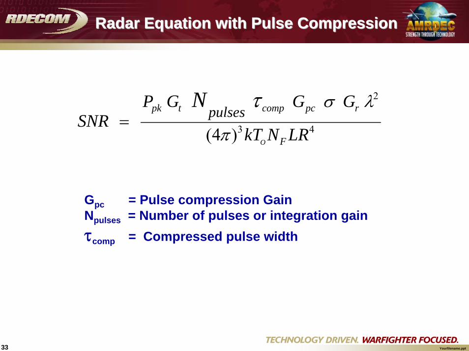
43
2
)4(
LRNkT
GGGPSNR
F
rpccomptpk
O
pulsesN
π
λστ=
Gpc = Pulse compression GainNpulses = Number of pulses or integration gainτcomp = Compressed pulse width
Radar Equation with Pulse CompressionRadar Equation with Pulse Compression
34 Yourfilename.ppt
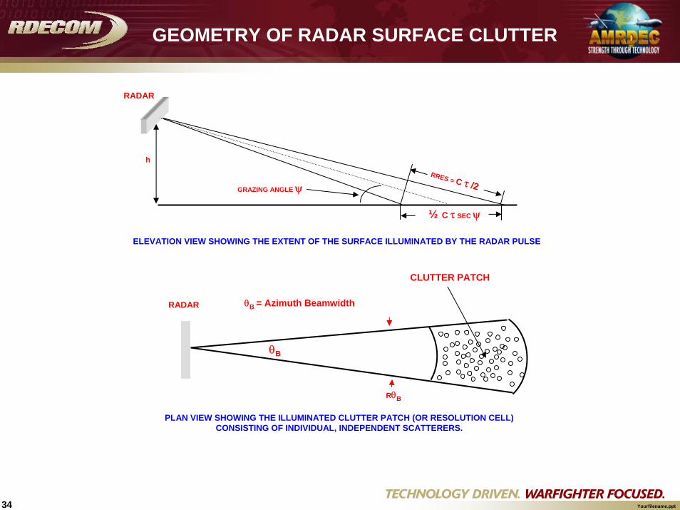
h
RRES = C τ /2GRAZING ANGLE ψ
RADAR
½ C τ SEC ψ
RADAR
CLUTTER PATCH
θB
RθB
PLAN VIEW SHOWING THE ILLUMINATED CLUTTER PATCH (OR RESOLUTION CELL)CONSISTING OF INDIVIDUAL, INDEPENDENT SCATTERERS.
ELEVATION VIEW SHOWING THE EXTENT OF THE SURFACE ILLUMINATED BY THE RADAR PULSE
θB = Azimuth Beamwidth
GEOMETRY OF RADAR SURFACE CLUTTER

35 Yourfilename.ppt
43
22
)4( ii
iiTc RL
GPP
i π
σλ=
Ground Clutter Signal LevelGround Clutter Signal Level
∑=i
cc iPP
GROUND RETURN WITHIN TARGET RANGE GATE (Pc)
RADAR RECEIVED POWER FROM TERRAIN CELL ( )
icP
⎟⎟⎠
⎞⎜⎜⎝
⎛=
n
cINT P
PGCNR
Clutter to Noise Ratio
36 Yourfilename.ppt
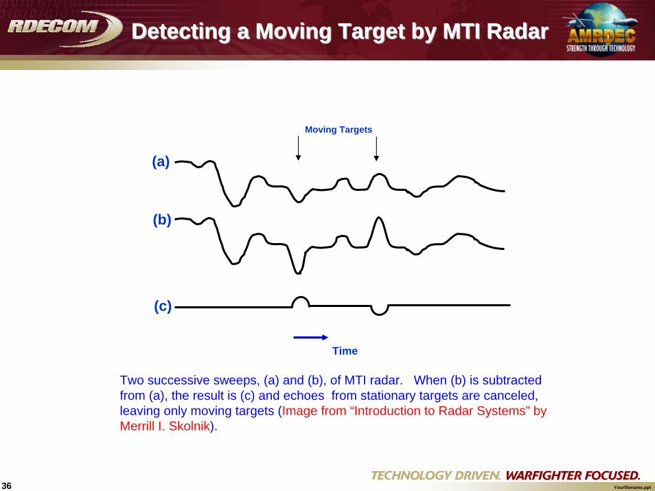
Time
Moving Targets
(a)
(b)
(c)
Detecting a Moving Target by MTI RadarDetecting a Moving Target by MTI Radar
Two successive sweeps, (a) and (b), of MTI radar. When (b) is subtracted from (a), the result is (c) and echoes from stationary targets are canceled, leaving only moving targets (Image from “Introduction to Radar Systems” by Merrill I. Skolnik).

37 Yourfilename.ppt
Moving Target Indicator ( MTI )
COMPUTE MAGNITUDE OF RAM'S DOPPLER VELOCITY
RELATIVE TO RADAR
EXIT
MTI
COMPUTE TOTAL CLUTTER SPECTRAL SPREAD VARIANCE
SELECT MTI FILTER TYPE
SINGLE-LOOP MTI CLUTTER CANCELLER
DOUBLE-LOOP MTI CLUTTER CANCELLER
N-POINT FFT WITHOUT CANCELLER
LOOP(S)
SINGLE CANCELLER
LOOP + N-POINT FFT
DOUBLE CANCELLER
LOOP + N-POINT FFT
COMPUTE SIR AT OUTPUT OF MTI FILTER
38 Yourfilename.ppt
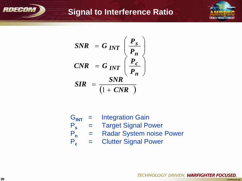
( )CNRSNRSIR
PPGCNR
PPGSNR
n
cINT
n
sINT
+=
⎟⎟⎠
⎞⎜⎜⎝
⎛=
⎟⎟⎠
⎞⎜⎜⎝
⎛=
1
GINT = Integration GainPs = Target Signal Power Pn = Radar System noise PowerPc = Clutter Signal Power
Signal to Interference Ratio
39 Yourfilename.ppt
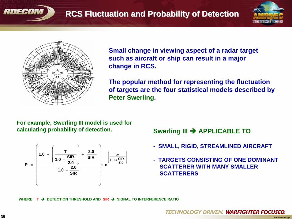
RCS Fluctuation and Probability of DetectionRCS Fluctuation and Probability of Detection
Small change in viewing aspect of a radar target such as aircraft or ship can result in a major change in RCS.
The popular method for representing the fluctuation of targets are the four statistical models described by Peter Swerling.
⎟⎟⎟⎟⎟⎟⎟
⎠
⎞
⎜⎜⎜⎜⎜⎜⎜
⎝
⎛
+×
⎟⎟⎟⎟⎟⎟⎟⎟⎟
⎠
⎞
⎜⎜⎜⎜⎜⎜⎜⎜⎜
⎝
⎛
+
+⎟⎟⎟⎟
⎠
⎞
⎜⎜⎜⎜
⎝
⎛
++
=2.0SIR1.0
T-
e
SIR2.01.0
SIR2.0
2.0SIR1.0
T 1.0
P
For example, Swerling III model is used for calculating probability of detection. Swerling III APPLICABLE TO
- SMALL, RIGID, STREAMLINED AIRCRAFT
- TARGETS CONSISTING OF ONE DOMINANT SCATTERER WITH MANY SMALLER SCATTERERS
WHERE: T DETECTION THRESHOLD AND SIR SIGNAL TO INTERFERENCE RATIO
40 Yourfilename.ppt
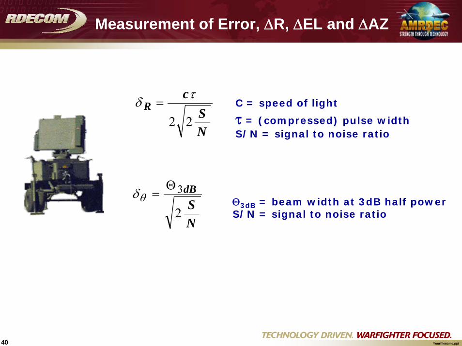
Measurement of Error, ΔR, ΔEL and ΔAZ
NS
cR
22
τδ =
NS
dB
2
3Θ=θδ
C = speed of light
τ = (compressed) pulse widthS/N = signal to noise ratio
Θ3dB = beam width at 3dB half power S/N = signal to noise ratio

41 Yourfilename.ppt
NSD2
λ
πδθ = λ = Wavelength
D = Distance between antennas S/N = signal to noise ratio
Measurement of Error ΔEL and ΔAZ Interferometer Base Radar
D
DTransmitter
Receiver Receiver
Receiver

42 Yourfilename.ppt
Random Sample in Modeling Radar Detection
TargetDetectable
SIR > 1
TargetDetectable
SIR > 1
DETECTIONDETECTION
ComputeProbability of
Detection(P0)
ComputeProbability of
Detection(P0)
μ > P0μ > P0Random
number(μ )
NO DETECTIONNO DETECTION
No
Yes
Yes
No
Swerling IIIwith 10-6 False
Alarm Rate
Swerling IIIwith 10-6 False
Alarm Rate
DETECTIONDETECTION
Normal Random Number where
σθ = δθσR = δR
Compute PerceivedTarget Location
by the Radar
Perceived Target Location (Range, Azimuth, Elevation )
ComputeSignal to Interference
Ratio (SIR)
ComputeSignal to Interference
Ratio (SIR)
REJECTION METHOD*
*The rejection method of generating random numbers drawn from particular distribution by rejecting those that fall outside the geometrical limits of the specific distribution.
σ
SIMULATED DETECTION BASED ON SIR
SIMULATED PERCEIVED LOCATION AS SEEN BY RADAR

43 Yourfilename.ppt
- Kalman filter is an estimation technique that utilizes measurement information to predict the best estimate of the true state at each measurement point.
- It is a recursive procedure which processes one measurement at a time until all measurements have been processed.
- This “best” estimate is a mix of predicted state estimate and a measured state estimate.
Extended Kalman Filter
- Generally Kalman Filter estimation techniques require that there is a mathematically linear relationship between the system states and measurement.
- When Kalman filter is applied to a nonlinear estimation problem, such as the calculation for IPP and LPP, as applied to radar tracking of ballistic projectiles, it is called Extended Kalman Filter.
Kalman Filter for Impact and Launch Point Prediction
44 Yourfilename.ppt
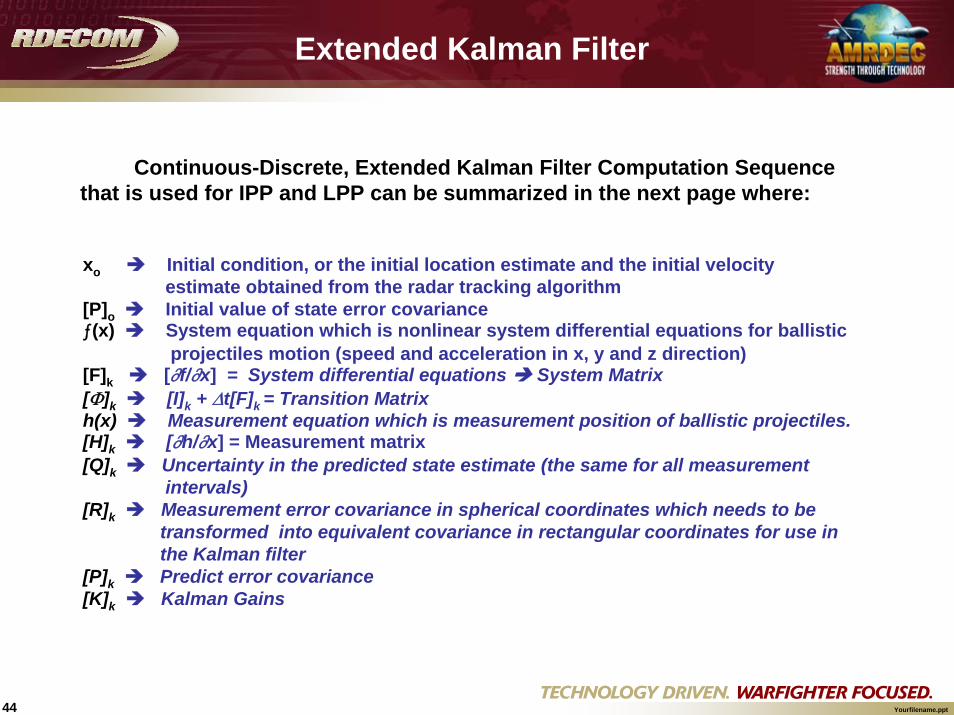
Continuous-Discrete, Extended Kalman Filter Computation Sequence that is used for IPP and LPP can be summarized in the next page where:
xo Initial condition, or the initial location estimate and the initial velocity estimate obtained from the radar tracking algorithm
[P]o Initial value of state error covarianceƒ(x) System equation which is nonlinear system differential equations for ballistic
projectiles motion (speed and acceleration in x, y and z direction)[F]k [∂f/∂x] = System differential equations System Matrix[Φ]k [I]k + Δt[F]k = Transition Matrixh(x) Measurement equation which is measurement position of ballistic projectiles. [H]k [∂h/∂x] = Measurement matrix[Q]k Uncertainty in the predicted state estimate (the same for all measurement
intervals)[R]k Measurement error covariance in spherical coordinates which needs to be
transformed into equivalent covariance in rectangular coordinates for use in the Kalman filter
[P]k Predict error covariance[K]k Kalman Gains
Extended Kalman Filter

45 Yourfilename.ppt
↓→→1Correct state estimate using current measurement and Kalman gains
9
↓
↓
↓
↓
↓
↓
↓
↓←←9
↓
FLOWEQUATIONS
Correct error covariance using gains
8
Compute Kalman Gains7
Predict error covariance6
Compute error covariance transition matrix
5
Compute measurement matrix4
Compute system matrix3
Predict state (example uses Euler integration)
2
Inputs at each iteration1
Initial Conditions0
DESCRIPTIONSTEP
[ ]oo Px ;ˆ
[ ] [ ]kk RQ ;txfxx kkk Δ+= −− )~(~~
11
[ ]kxx
k xxf
Fˆ
)(
=⎥⎦
⎤⎢⎣
⎡∂
∂=
[ ]kxx
k xxhH
~
)(
=⎥⎦⎤
⎢⎣⎡
∂∂
=
[ ] [ ] [ ]kk FtI Δ+=Φ
[ ] [ ] [ ] [ ] [ ]kTkkkk QPP +ΦΦ= −1
~
[ ] [ ] [ ] [ ] [ ] [ ] [ ][ ] 1~~ −+= k
Tkkk
Tkkk RHPHHPK
[ ] [ ] [ ] [ ][ ][ ]kkkk PHKIP ~−=
[ ] ))~((~ˆ kkkkk xhzKxx −+=
Extended Kalman Filter Computation Sequence

46 Yourfilename.ppt
Radar Flow Chart in IDEEASRadar Flow Chart in IDEEAS
Radar ModelRadar Model
LOSto Target
LOSto Target
Is TargetIn Beam?Is TargetIn Beam?
TargetDetectable(SNR > 1)
TargetDetectable(SNR > 1)
PerformBeam
Scanning
PerformBeam
Scanning
ComputeTarget RadarCross Section
ComputeTarget RadarCross Section
Compute Signal to Noise Ratio
(SNR)
Compute Signal to Noise Ratio
(SNR)
A B
No
No
No
Yes
Yes
Yes
MissileDetectable
SIR > 1
MissileDetectable
SIR > 1
DETECTIONDETECTION
ComputeProbability of
Detection(P0)
ComputeProbability of
Detection(P0)
Update TrackingFiles
Update TrackingFiles
ExitExit
A B
ComputeSignal to Interference
Ratio (SIR)
ComputeSignal to Interference
Ratio (SIR)
μ > P0μ > P0Random
number(μ )Random
number(μ )
NO DETECTIONNO DETECTION
EnoughPoints forPrediction
EnoughPoints forPrediction
Predict ImpactLocation and Send
Warning to Field Commander
Predict ImpactLocation and Send
Warning to Field Commander
No
Yes
Yes
No
Prediction(LPP & IPP) No
Yes
Swerling IIIwith 10-6 False
Alarm Rate
Swerling IIIwith 10-6 False
Alarm Rate

47 Yourfilename.ppt
Radar ModelRadar Model
Conceptual software design document for our radar model.
Description:
CR Created: <this single CR that lead to the creation of the model >
CRs Related: <this is a list, to be constantly amended, for all CRs after the
initial creation that touched this particular model in any way>

48 Yourfilename.ppt
Class DiagramClass Diagram
Sensor<<interface>>
HiFidelityRadar
SensorType
<<interface>>
HiFidelityRadarType
<<interface>>
Antenna

49 Yourfilename.ppt
Class Diagram(more detailed)Class Diagram(more detailed)
Sensor
<<interface>>
HiFidelityRadar
EapsCmcbSensor
SensorType
<<interface>>
HiFidelityRadarType
EapsCmcbSensorType<<interface>>
Antenna
PhasedArrayAntenna

50 Yourfilename.ppt
Sequence DiagramSequence Diagram
EapsCmcbSensor : Sensor Antenna
boolean scanTarget()
detect()
double getAntennaGain()
updateTrackFile()

51 Yourfilename.ppt
Conclusion Conclusion
DMSO - RPGSimone Youngblood’s Brief
DoDAFOur team uses three “types” of Conceptual
Models to communicate in a iterative, recursive manner from the “developer to user”.
In preparing for this brief, I found few people with a common definition of conceptual modeling; however, everyone possessed a common understanding of tailoring products and processes in order to achieve effective communication.