Conceptual development of a ‘finger’ style pushing trap ...Conceptual development of a...
33
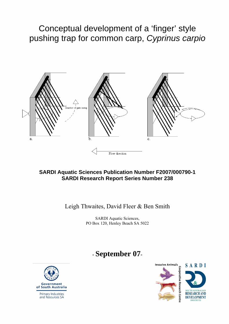
Conceptual development of a ‘finger’ style pushing trap for common carp, Cyprinus carpio SARDI Aquatic Sciences Publication Number F2007/000790-1 SARDI Research Report Series Number 238 Leigh Thwaites, David Fleer & Ben Smith SARDI Aquatic Sciences, PO Box 120, Henley Beach SA 5022 - September 07-
Transcript of Conceptual development of a ‘finger’ style pushing trap ...Conceptual development of a...
Conceptual development of a ‘finger’ style pushing trap for common carp, Cyprinus carpio
SARDI Aquatic Sciences Publication Number F2007/000790-1 SARDI Research Report Series Number 238
Leigh Thwaites, David Fleer & Ben Smith
SARDI Aquatic Sciences, PO Box 120, Henley Beach SA 5022
- September 07-

..
This publication should be cited as: Thwaites, L., Fleer, D., Smith, B. (2007). Conceptual development of a ‘finger’ style pushing trap for common carp. SARDI Aquatic Sciences Publication Number F2007/000790-1. SARDI Research Report Series Number 238. Prepared by the South Australian Research and Development Institute (Aquatic Sciences), Adelaide. 33 pp.
South Australian Research and Development Institute SARDI Aquatic Sciences, PO Box 120, HENLEY BEACH, SA 5022. Telephone: 8207 5400 Facsimile: 8207 5481 DISCLAIMER The authors warrant that they have taken all reasonable care in producing this report. The report has been
through the SARDI Aquatic Sciences internal review process, and has been formally approved for release by the
Chief Scientist. The recommendations given in this report are based on the best available information at the time
of writing. The South Australian Research and Development Institute (SARDI) makes no warranty of any kind,
expressed or implied, concerning the use of the information mentioned in this report.
© 2007 SARDI AQUATIC SCIENCES.
This work is copyright. Except as permitted under the Copyright Act 1968, no part of this report may be
reproduced by any process, electronic or otherwise, without specific written permission of the author. Neither
may information be stored electronically in any form whatsoever without such permission. All photographs and
drawings remain the property of the authors.
Author(s): Drs Leigh Thwaites and Ben Smith, and David Fleer Reviewers: Dr Michael Steer and Chris Bice Approved by: Dr Qifeng Ye
Signed:
Date: 13 September 2007 Distribution: SARDI Aquatic Sciences and the Invasive Animals CRC Circulation: Unrestricted
.

..
TABLE OF CONTENTS
EXECUTIVE SUMMARY............................................................................................................................................... 4
BACKGROUND ............................................................................................................................................................... 5
SECTION 1: CONCEPTUAL DEVELOPMENT OF THE ‘FINGER’ STYLE PUSHING TRAP ........................ 7
SECTION 2: USING CARP MORPHOMETRIC DATA TO DEFINE THE STRUCTUAL DIMENSIONS OF THE ‘FINGER’ STYLE PUSH TRAP ................................................................................................. 11
2.1 INTRODUCTION....................................................................................................................................................... 11 2.2 METHODS ............................................................................................................................................................... 11 2.3 RESULTS & DISCUSSION......................................................................................................................................... 12
SECTION 3: THE PUSHING POWER OF CARP ..................................................................................................... 13
3.1 INTRODUCTION....................................................................................................................................................... 13 3.2 METHODS ............................................................................................................................................................... 13
3.2.1 Site ................................................................................................................................................................... 13 3.2.2 Fishing Rig and Bait ........................................................................................................................................ 14 3.2.3 Fishing Method................................................................................................................................................ 14
3.3 RESULTS & DISCUSSION......................................................................................................................................... 15
SECTION 4: MATCHING FINGER WEIGHTS TO CARP PUSHING CAPACITY ............................................ 17
4.1 INTRODUCTION....................................................................................................................................................... 17 4.2 MATERIALS & METHODS ....................................................................................................................................... 17 4.3 RESULTS & DISCUSSION......................................................................................................................................... 20
SYNTHESIS .................................................................................................................................................................. 23
PROSPECTUS FOR FUTURE RESEARCH .............................................................................................................. 27
ACKNOWLEDGEMENTS............................................................................................................................................ 28
REFERENCES................................................................................................................................................................ 29
APPENDIX A: VALIDATION OF CARP PULLING POWER ESTIMATES ........................................................ 31
3.

..
4.
EXECUTIVE SUMMARY
Common carp (Cyprinus carpio) make annually predictable migrations between habitats for
over-wintering (deep river channels) and summer spawning (shallow wetlands). Their movements
result in localised accumulations at migration barriers (weirs, carp exclusion screens), which may
persist for several months. Accumulated carp are aggressive in their attempts to push underneath
barriers to their migration. Thus, we have conceptually developed a novel ‘pushing trap’, with
design specifications that are tailored to the pushing abilities and morphology of a targeted size
range of carp (>250 mm Total Length). The final ‘finger style’ push trap design was selected in
preference to four others. It can be constructed from readily available materials, retrofitted to
existing carp separation cages and carp exclusion screens, or adapted into mobile ‘rapid response’
cages. This new technology promises a unique opportunity for targeted removal programs, and may
be applicable to other vertebrate pests that experience population bottlenecks at times when
migratory pathways become spatially constrained.

..
BACKGROUND
In temperate lowland rivers, common carp (Cyprinus carpio) appear allied with two broad habitats:
marsh-like habitats, preferably in off steam wetlands during late spring / early autumn, and deep
water habitats in the main river channel during winter (Diggle et al. 2004; Smith 2005). The
shallow habitat enables spawning and the replenishment of populations via recruitment. The deep
habitat is thought to provide refuge from flow and maintain stable temperatures in comparison with
surface waters. Movement between these two habitats is annually predictable, as is evidenced
(particularly during spring) by localised accumulations of carp at migration barriers (see below).
Spawning movements and accumulations are vulnerable to targeted removal programs and allow
focussed carp management efforts. In this way, William’s Carp Separation Cages (CSC) are now
being retrofitted to existing fishways along the River Murray to capture migrating carp by
exploiting their innate jumping abilities (see, Stuart et al. 2006).
The idea of a pushing trap for common carp was first conceived following observations of carp
trying to push underneath barriers in laboratory flumes (Dooland et al. 2000). Similar observations
are made annually (mid-August to mid-November) within the main stem of the River Murray and at
the inlets to off-stream wetlands; wherever the longitudinal and lateral migration of carp is blocked
either by weirs or by carp exclusion screens, respectively. Typically, the fish are undeterred by the
actions of bystanders and wounds on their heads emphasize their persistent attempts to
jump over and/or push underneath such barriers. This pushing behaviour is continuous during the
day and night, and has been observed to be most frantic when water is out-flowing from wetlands
(BS, Pers. Obs.). Wetland water is speculated to comprise physical (current-flow),
physiological (temperature) and chemical (dissolved organic and inorganic chemical compounds)
properties that might act independently, or in a synergistic manner, as carp sensory attractants
(Smith and Thwaites 2007). Effectively, this ‘soup’ of attractants appears to create a directional cue
(a gradient from the wetland to the main channel) that carp detect and pursue.
Persistent, intense pushing behaviour appears unique to common carp; to our knowledge,
large-bodied native fishes do not associate with large aggregations of carp and have not been
observed pushing against in-situ barriers (BS, Pers. Obs.). Thus, pushing traps show considerable
potential as an Achilles’ heel control option, which exploit the species’ (apparently) unique pushing
abilities.
5.

..
Pushing traps for common carp are now being investigated as part of a 3-year research project
entitled ‘Spawning migrations and attractant flows: Achilles’ heel exploitation of innate carp
behaviours’ (Project 4.F.12). This project is led by the South Australian Research and Development
Institute (SARDI Aquatic Sciences) in collaboration with The University of Adelaide, and with
financial support from the Invasive Animals Cooperative Research Centre (IA CRC). The aims are
threefold:
1) Evaluate the potential application of existing Carp Separation Cage (CSC) technology for
trapping and removing carp at wetland inlets i.e. develop wetland CSCs.
2) Modify the existing CSC design for wetlands to incorporate a ‘pushing trap component’, and
compare the virtues of traditional jumping traps with those of novel pushing traps.
3) Assess the potential for using sensory attractants to optimise the uptake of carp into traps.
This report addresses the second aim. It documents the scope of research that has led to the
development and design of a pushing trap for common carp, which is ready for preliminary field
testing. Specifically, we:
1) Evaluated five conceptual configurations for a carp pushing trap and elected to pursue the
‘finger’ style configuration.
2) Established the size range of carp that should be targeted.
3) Calculated finger apertures, according to body morphometrics data, to capture fish of the
targeted size range.
4) Indirectly estimated the pushing power of carp from in-field measurements.
5) Matched the weight of the fingers to the known pushing capacity of carp.
Each research component is explained in a separate section of this report, aside from components
2 & 3, which are presented together in Section 2. Key results are drawn together in the synthesis
where the final ‘finger’ style pushing trap design is also presented. The report concludes with a
Prospectus for Future Research.
6.
..
SECTION 1: CONCEPTUAL DEVELOPMENT OF THE
‘FINGER’ STYLE PUSHING TRAP
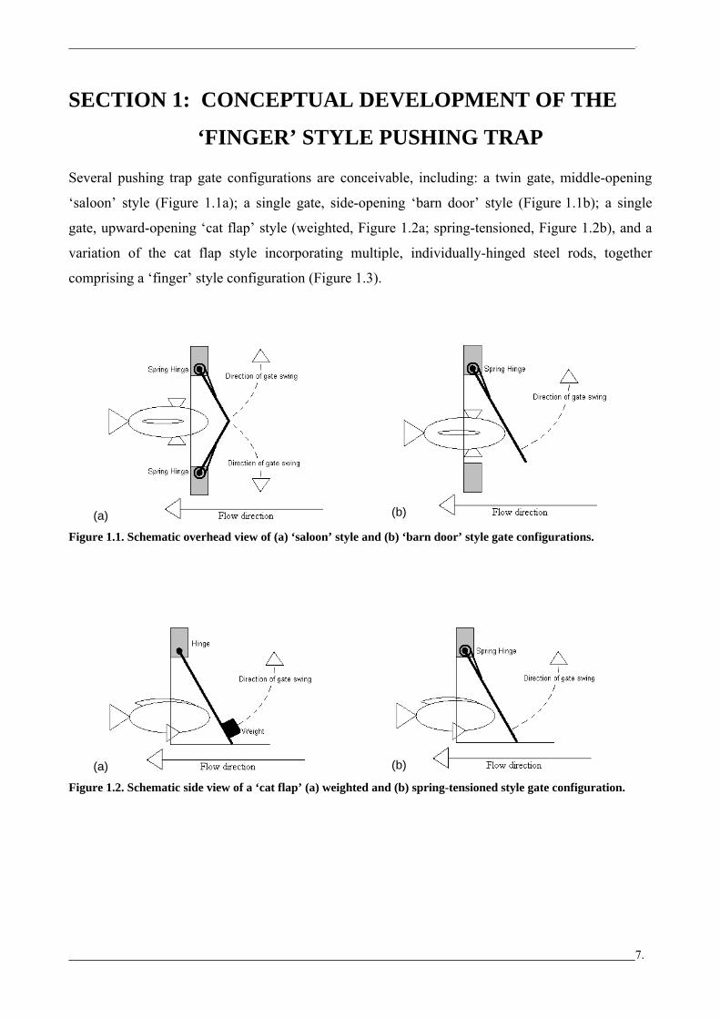
Several pushing trap gate configurations are conceivable, including: a twin gate, middle-opening
‘saloon’ style (Figure 1.1a); a single gate, side-opening ‘barn door’ style (Figure 1.1b); a single
gate, upward-opening ‘cat flap’ style (weighted, Figure 1.2a; spring-tensioned, Figure 1.2b), and a
variation of the cat flap style incorporating multiple, individually-hinged steel rods, together
comprising a ‘finger’ style configuration (Figure 1.3).
7.
(a) (b)
Figure 1.1. Schematic overhead view of (a) ‘saloon’ style and (b) ‘barn door’ style gate configurations.
(a) (b) Figure 1.2. Schematic side view of a ‘cat flap’ (a) weighted and (b) spring-tensioned style gate configuration.

..
8.
Figure 1.3. Schematic 3-D side view of the ‘finger’ style variation of the ‘cat flap’ configuration - a) carp
approach the trap, b) force their way through single or multiple fingers, depending on their body size, and c) the
finger(s) close, entrapping the carp.
Preliminary considerations highlighted that both the ‘saloon’ and ‘barn door’ style configurations
would be complex to construct and maintain, as they would require the development of hinging
points tensioned by spring mechanisms (weighting will not work on these styles1); both
components are delicate and susceptible to corrosion. A second and potentially more serious
limitation is that the lower edges of the gates would be subject to fouling from the accumulation of
sediments and debris, which would compromise their operation. A ‘cat flap’ style configuration, on
the other hand, has several advantages over the ‘saloon’ and ‘barn door’ style configurations:
1) It exploits the preference of carp to push their way underneath (not through) barriers.
2) The gate mechanism may be either spring-tensioned or weighted.
3) If there is sediment accumulation, the gate will still have substantial closing capacity as the
hinging mechanism is well off the ground and, in the worst case scenario, the gate will rest
heavily on the sediments. Continuous opening of the flap, combined with the forceful
swimming action of carp as they pass underneath it, may even be sufficient to prevent
sediment and debris build-up.
1 The use of weights is particularly appealing, since they are technically simple and the potential for operational failures associated with them is virtually zero.

..
4) The closed weight of the flap and the instantaneous force required to lift it can be increased
by setting the flap at an angle (i.e. 22.5o). It is conceivable that this inclination in the barrier
might even encourage the onset of investigative carp pushing behaviours.
The ‘finger’ style variation of the ‘cat flap’ configuration has three advantages. First, it only
requires carp to force past one or more fingers (depending on body size), instead of an entire gate.
This should minimize the trapping of non-target species, which may be inherently reluctant to force
their way underneath a barrier but which simply follow carp as they push open the flap. Second, by
varying the weight and dimensions of the fingers, and the apertures between them, the ‘finger’ style
trap can be tailored to target specific size-classes of carp. Third, the finger apertures will minimise
the potential for ‘clogging’ by allowing the passage of up-current debris. Thus, the ‘finger’ style
pushing trap was considered the most appropriate for further development.
9.


..
11.
SECTION 2: USING CARP MORPHOMETRIC DATA TO
DEFINE THE STRUCTUAL DIMENSIONS
OF THE ‘FINGER’ STYLE PUSH TRAP
2.1 INTRODUCTION
To design a ‘finger’ style pushing trap for carp, it is essential to consider the morphometrics
(body dimensions) of the targeted size-range. To be effective, the spacing between the fingers
(the aperture) should be slightly less than the mean width of the smallest targeted individuals, and
the trap depth must permit the passage of the largest targeted individuals (allowing 10% body
compression, see below). In this study, we nominate a targeted size range of carp of 250-770 mm
total length (TL). The minimum size of 250 mm TL is well below the estimated 350 mm TL at
which the majority of carp are sexually mature (Sivakumaran et al. 2003; Smith and Walker 2004)
and ecologically most destructive (Smith 2005). The maximum size class of 770 mm TL is the size
of the longest carp for which we have morphometrics data, but it still rivals the longest carp ever
recorded from scientific sampling, which is 760 mm fork length (FL, ~790 mm TL; Stuart and
Jones 2002).
2.2 METHODS
Morphometrics data from 113 carp captured during mid-August to mid-November 2006 at six
wetlands downstream of Weir 1 on the River Murray, South Australia (SARDI Aquatic Sciences
and The University of Adelaide, Unpub. Data) was analysed to identify the body dimensions
(width and depth) of the targeted size range of carp (250-770 mm TL). These values were
subsequently reduced by 10%, to compensate for the estimated (unquantified) body compression of
carp attempting to force their way through/underneath barriers.

..
2.3 RESULTS & DISCUSSION
There were strong linear relationships between body width and length and body depth and length
with length explaining 93 and 94% of the variation, respectively (Fig. 2.1). The mean width of a
250 mm (TL) carp was calculated to be 34.6 mm and the mean depth of a 770 mm (TL) carp was
182.7 mm. Thus, allowing for 10% body compression, the aperture that the fingers need to be
separated by to capture carp ≥ 250 mm is 31.2 mm, and the depth of the pushing trap should be at
least 164.4 mm to enable the unimpeded passage of the largest carp.
Total length (TL, mm)
0 100 200 300 400 500 600 700 800
Bod
y w
idth
/ de
pth
(mm
)
0
25
50
75
100
125
150
175
200 Body width versus length
width = 0.16.length - 5.38, r2 = 0.93, n = 113)Body depth versus length
depth = 0.22.length + 13.29, r2 = 0.94, n = 113)
Figure 2.1. Linear regression of the body dimensions (width/depth versus length) of 113 carp captured during
mid-August to mid-November 2006, from six wetlands in the lower River Murray.
12.
..
13.
SECTION 3: THE PUSHING POWER OF CARP 3.1 INTRODUCTION
Morphometrics data can inform the calculation of suitable finger dimensions and apertures
but knowledge of the pushing capacity of carp is required to identify appropriate finger weights.
Whilst in-situ measurements of carp pushing power had not previously been explored, Mitsugi and
Inuoe (1985) measured the ex-situ pulling force of small carp (body weight ≈ 16 to 100 g) in the
laboratory, using a strain meter in conjunction with disparate fishing rods and hooking
methods. Briefly, their results from flexible fishing rods may have underestimated the actual pulling
forces (due to potential energy loss associated with rod movement and flex) but those from iron
fishing rods would be most accurate, and suggested that carp pulled with a force of ~1-2 times their
body weight.
Whilst the above information is informative, the study did not include individuals of the desired
size-range for trapping (250-770 mm TL), and as with all laboratory studies, the application of the
data to field situations may be questioned, as the laboratory (ex-situ) conditions may have affected
the volitional response of fish (Dooland et al. 2000; Mallen-Cooper 1996). Thus, in this study, we
sought to indirectly estimate the in-situ pushing power of carp via pulling measurements obtained
from line-hooked individuals2.
3.2 METHODS
3.2.1 Site
Sampling occurred during late summer and early autumn 2007 within the main lake of the Torrens
River (GPS co-ordinates, 280923E, 6133338N) and within the ‘duck pond’ of the Adelaide
Botanical Gardens (281561E, 6133232N). Both sites had negligible (zero) current-flow at the times
of sampling.
2 Although carp pulling and pushing power are directly related (see Appendix A), it is noted that measurements taken
from line-hooked fish may still underestimate the true pushing power of carp. Underestimates would arise when
mouth-hooked fish fail to swim or fight directly against the anchoring point, thereby resulting in potential losses in the
applied force.

..
3.2.2 Fishing Rig and Bait
The fishing rig consisted of non-stretch braided-line, attached via a swivel to two short lengths of
monofilament line, weighted with a small running-sinker placed above the swivel. The swivel and
each of the fishing lines had a breaking strain of 30 kg. Size 2, 4, 6 and 8 hooks were interchanged
according to the predominant size of carp present. This rig was attached to a Pesola 10 kg
(100 g increments) spring scale, fitted with a maximum weigh indicator. The Pesola scale was
secured to the bank using a steel star picket and supported in the horizontal plane using a standard
fishing rod holder (Figure 3.1). This rig ensured a direct transfer of energy (force) to the scale by
minimising potential energy losses associated with flexible fishing rods and high-stretch
light-monofilament lines.
Figure 3.1. Schematic of the rig used to measure the in-situ pulling (= pushing) power of carp.
Several baits were used interchangeably including tiger worms, corn kernels, and a breadcrumb and
water mixture. Vanilla essence was incorporated into the breadcrumb mixture and poured over the
corn kernels as a carp sensory attractant. The mixture of bread crumbs and vanilla essence was
found to be most effective.
3.2.3 Fishing Method
At each location, the fishing rig was secured to the bank using a steel star picket. Approximately 3
m of line was attached to the Pesola scales using several half-hitch knots. The baited rig was cast
and adjusted to achieve a slightly slack line. Each rig was constantly attended. Although bites could
be felt though a tight line, more hook-ups were achieved by allowing the fish to take the bait over a
short distance (~30 cm) before striking. Once a fish was hooked, the line was dropped and the fish
was allowed to run/fight. To ensure the spring-scale pointed directly at the fish, it was removed
14.

..
from its support during the hooking process; in most instances the force of the initial strike was
sufficient to achieve this. Hooked carp were only landed once the fighting response had ceased,
although the maximum pull was typically registered on the initial run. Once landed, fish length
(mm) was recorded using a standard measuring board, fish weight (g) was recorded using electronic
scales (A&D CO. Ltd. Max 5000 g, d=1 g), and pulling power was recorded from the Pesola scales.
For descriptive and modelling purposes pulling (= pushing) power is related to fish weight.
3.3 RESULTS & DISCUSSION Fifty-seven carp were captured but only 44 registered a measurable pulling response (mean length
403 mm, range 155-635 mm TL; mean weight 1526 g, range 58-4434 g). Figures 3.2 and 3.3
illustrate the weight-length and pulling power-weight relationships for those 44 carp, respectively.
y = 28.406e0.008x
R2 = 0.9762
0500
100015002000250030003500400045005000
0 100 200 300 400 500 600 700
Length (mm)
Wei
ght (
g)
Figure 3.2. Weight-length relationship of carp registering a measurable pulling response (n = 44).
y = 2.0482xR2 = 0.8375
0100020003000400050006000700080009000
10000
0 1000 2000 3000 4000 5000
Carp Weight (g)
Pul
ling
Pow
er (g
)
Figure 3.3. Carp pulling power exhibits a strong linear relationship with fish weight (R2=0.85, n=44, figure 4)
with carp typically pulling (pushing) approximately twice their body weight.
15.
..
Regression analyses of carp pulling (=pushing) power versus body weight, collated from in-situ
pulling measurements obtained from line-hooked individuals, indicate that carp can pull (push)
approximately twice their body weight (pulling force = 2.0482 x body weight, r2=0.84, n = 44,
Figure 3.3). These results support the laboratory estimates for smaller carp presented by
Mitsugi and Inoue (1985), and allow suitable weightings for the ‘fingers’ to be calculated. Those
weightings must relate to the weight and pulling (pushing) power of the targeted size range of carp.
Thus, pushing trap ‘fingers’ that require an approximate pushing force of 430 g to lift should allow
the passage of all carp ≥ 250mm (mean body weight, ~210 g; Figure 3.2), whilst ensuring that the
finger is of sufficient weight to quickly drop once the fish have entered the trap.
As a ‘finger’ style gate has a pendulum-based movement, the force required to lift each finger
increases as it is lifted from the resting position (Figure 4.3). This should not pose any significant
problems, as the amount that the finger is required to be lifted will co-vary with fish size i.e. smaller
fish will only need to force the finger a small distance before they can enter the trap. Larger carp
will easily be able to enter the trap, as even a 360 mm fish has a pushing capacity of >1000 g; the
greatest pushing force registered in this study was 8400 g by an in individual of 610 mm TL and
3.56 kg body weight. Based on the body morphometrics data from Section 1 and the dimensions of
the proposed pushing trap element (Synthesis, Figure 5.1), all carp <610 mm will need to push
past/underneath at least one finger, whilst carp >610 mm will need to push past/underneath at least
2 fingers.
16.

..
17.
SECTION 4: MATCHING FINGER WEIGHTS TO CARP
PUSHING CAPACITY 4.1 INTRODUCTION A pushing trap ‘gate’ should be spring-tensioned or weighted in a way that allows the passage of
the targeted size range of carp yet still be sufficiently weighted to ‘snap shut’ once an individual has
passed the gate and entered the trap. The previous investigation indicated that a 250 mm TL carp
(minimum targeted size class) can push approximately 430 g. Thus, to permit the passage of all carp
equal to or greater than this size class, the push trap fingers must be designed and weighted so that
the force required to lift one finger does not exceed 430 g. Consequently, the aims of the present
study were to:
1) Design and manufacture disparate finger configurations.
2) Evaluate the force required to lift each configuration.
3) Identify the most suitable configuration for preliminary field trials.
4.2 MATERIALS & METHODS
The conceptual design of the ‘finger’ style pushing trap (Fig. 1.3), shows a barrier of fingers hinged
from a supporting shaft that runs the width of the trap. This configuration allows any number of
fingers to be added to the shaft depending on the required span of the pushing trap. To determine
the most suitable finger configuration, several materials were tested. Fingers consisted of solid mild
steel or galvanized tubular steel. These fingers were arc-wielded to tubular galvanized or tubular
stainless steel sleeves (Fig 4.1). The four ‘finger’ configurations tested are given in table 4.1. For
this study, 19 mm (diameter) stainless steel was used for the supporting shaft. Stainless steel was
chosen to avoid problems associated with corrosion.

..
Figure 4.1. Schematic front view of finger configuration
Table 4.1. Summary of the four different configurations of construction material for the fingers and their sleeves
that were trialled to evaluate the force required to lift each configuration.
Finger type & Component Material Length (mm)
Diameter* (mm)
Total weight (g) Comment
34 (out)
27 (int)
Finger Mild steel 210 25.4
25 (out)
21 (int)
Finger Mild steel 220 25.4
21 (out)
19.5 (int)
Finger Mild steel 225 24
25 (out)
21 (int)
27 (out)
21 (int)
* The sleeves from all finger types were fitted to a solid stainless-steel shaft measuring 19 mm diameter.
210
837.3Stainless steel sleeves with reduced
internal dimensions were used to test a tighter fit on the supporting shaft
SGT
Sleeve Stainless steel 64
401Stainless steel sleeves were used to avoid fouling from rust. Galvanized tube was
used to evaluate a lighter materialFinger Galvanised tubular steel
SM2Sleeve Stainless steel
These materials were used as they were readily available in the SARDI Aquatic
Sciences work-shop
SM1Sleeve Stainless steel 63
942.4
A stainless steel sleeve with a relatively large internal dimension was selected to avoid fouling from rust and other debirs.
Mild steel was used for its weight.
GMSleeve Galvanized tubular steel 65
63
989
The force required to lift each finger(s) to various heights (angular degrees) was measured using a
Pesola Medio-Line spring scale (2500 g max, 20 g increments) with a maximum weigh indicator,
and a protractor style board. The protractor consisted of a sheet of heavy cardboard with increments
marked every 11.25°, from 0-90°. A circular hole was made at the right angle of the protractor to fit
the 19 mm stainless steel supporting rod. This rod was secured and levelled in a bench-vice before
the protractor board (also levelled) and experimental fingers were fitted (Figure 4.2).
18.
..
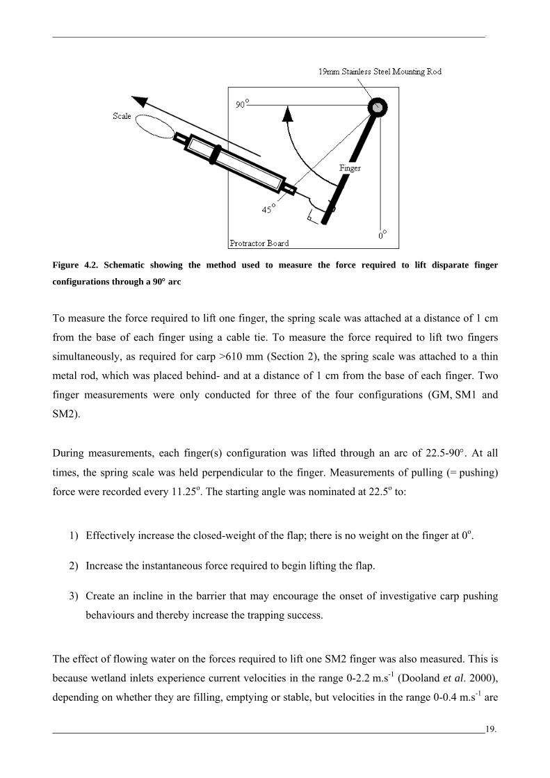
Figure 4.2. Schematic showing the method used to measure the force required to lift disparate finger
configurations through a 90° arc
To measure the force required to lift one finger, the spring scale was attached at a distance of 1 cm
from the base of each finger using a cable tie. To measure the force required to lift two fingers
simultaneously, as required for carp >610 mm (Section 2), the spring scale was attached to a thin
metal rod, which was placed behind- and at a distance of 1 cm from the base of each finger. Two
finger measurements were only conducted for three of the four configurations (GM, SM1 and
SM2).
During measurements, each finger(s) configuration was lifted through an arc of 22.5-90°. At all
times, the spring scale was held perpendicular to the finger. Measurements of pulling (= pushing)
force were recorded every 11.25o. The starting angle was nominated at 22.5o to:
1) Effectively increase the closed-weight of the flap; there is no weight on the finger at 0o.
2) Increase the instantaneous force required to begin lifting the flap.
3) Create an incline in the barrier that may encourage the onset of investigative carp pushing
behaviours and thereby increase the trapping success.
The effect of flowing water on the forces required to lift one SM2 finger was also measured. This is
because wetland inlets experience current velocities in the range 0-2.2 m.s-1 (Dooland et al. 2000),
depending on whether they are filling, emptying or stable, but velocities in the range 0-0.4 m.s-1 are
19.
..
most common (Smith et al., Unpub. Data). Trials were conducted in the University of Adelaide’s
Department of Civil and Environmental Engineering flume tanks. During measurements, the
supporting shaft and fingers were supported in a frame constructed from heavy gauge ‘angle’ iron.
The frame was submerged in water flowing (approximately 1 m.s-1) against the direction of
finger-lift and the force required to lift one finger to 22.5o, 45o and 90o was measured.
To compare recorded force with carp morphometric data, finger height measurements relative to
each incremental (11.25o) increase in the angular degree of the fingers were also taken. The zero
reference point for these measurements was taken from a horizontal line extending from the base of
the finger when held at 22.5o.
4.3 RESULTS & DISCUSSION
Of the four ‘finger + sleeve’ configurations tested, only the SM2 configuration was considered
suitable for further evaluation. This was due to the following three factors:
1) The GM, SM1 and SGT configurations had high levels of ‘free play’ associated with their
larger sleeve dimensions. Free play is undesirable as it alters the effective aperture between
fingers and this would affect the predicted size range of carp captured (or let through).
2) The force required to lift GM and SM1 did not differ greatly from SM2
3) The SGT configuration was considered too light to effectively ‘snap shut’ (Table 4.1).
The force required to lift one and two SM2 fingers to 90o is approximately 410 g and 860 g,
respectively (Figure 4.3). The closed weight (equal to the instantaneous lifting force) of one and
two fingers at 22.5o was 120 g and 300 g, respectively. With regard for the body morphometrics and
pushing power of carp, the maximum height and force required to lift one or two fingers can be
estimated. For example, for a 250 mm TL carp to pass directly underneath a finger, it would need to
lift that finger by a height of ~61.5 mm (allowing 10% body compression), which would require a
force of ~220 g (dashed line, figure 4.3). While we have calculated the force required to lift one or
two fingers to the height of a 250 mm carp’s body depth, it is realistic to assume that carp will slip
between the finger being lifted and an adjacent finger before this height is reached; thus, the actual
force required may be much reduced (see Figure 4.3).
20.

..
Flowing water was found to have a minimal additive effect on the pulling (= pushing) forces
required to lift one finger, and this effect decreased with the height that the finger was lifted
(Figure 4.3). In this case, the instantaneous lifting force for one finger in flowing water (1 m.s-1)
increased from 120 to 200 g, which is well within the pushing abilities (430 g) of the smallest size
class (250 mm TL) of carp targeted, and should aid in effectively closing the finger.
0
100
200
300
400
500
600
700
800
900
1000
22.5 33.75 45 56.25 67.5 78.75 90
Degrees
Push
ing
Forc
e (g
)
0
50
100
150
200
250
Fing
er H
eigh
t (m
m)
SM22 SM2SM2 - Flowing waterHeight data
Figure 4.3: Force required to lift the various finger configurations (primary y-axis), and the height of the base of
the fingers (secondary y-axis), in relation to the angular degrees (from 22.5 - 90°). The dashed line represents the
maximum height that a 250 mm TL carp is required to lift one finger.
21.

..
23.
SYNTHESIS
The ‘finger’ style pushing trap for common carp, which is described herein and 1) exploits the
innate pushing abilities of an invasive vertebrate pest and 2) promises species-specificity by
matching design elements to ecological and morphometric information, is a novel one. In fact, to
our knowledge, we believe this is the first of its kind - even though other traps that operate on a
similar premise exist. For example, pushing traps for redfin perch (Perca fluviatilis), which utilise
simple plastic tree tags to successfully deter (not prevent) escapement from traditional
‘Windermere’ traps, have been tested in English lakes (Fisher and Herrod 1986). Species-specificity
was not mentioned but would seem unlikely due to the flimsy nature of the pushing trap element
(the plastic tags). Other pushing traps for capturing broods of Richardson’s ground squirrels
(Spermophilus richardsoni, Wobeser and Leighton 1979) and burrowing owls
(Athene cunicularia, Winchell 1999) are conceptually similar, but their designs are akin to a
‘cat flap’ configuration (see Section 1) and therefore have operational differences.
The ‘finger’ style pushing trap for common carp was selected over four other potential designs due
to mechanical and design advantages, plus an ability to tailor the depth, weight and aperture of the
fingers to match the pushing abilities and body dimensions of the targeted size class of carp
(Table 5.1).
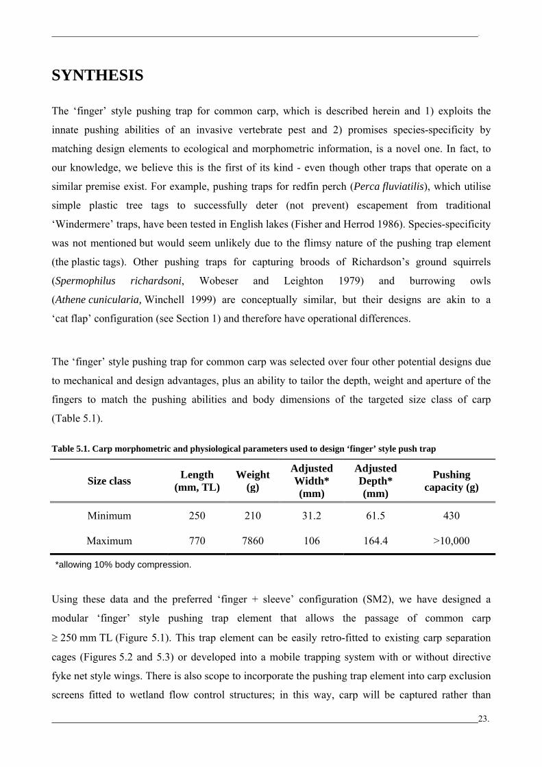
Table 5.1. Carp morphometric and physiological parameters used to design ‘finger’ style push trap
Size class Length (mm, TL)
Weight (g)
Adjusted Width* (mm)
Adjusted Depth* (mm)
Pushing capacity (g)
Minimum 250 210 31.2 61.5 430
Maximum 770 7860 106 164.4 >10,000
*allowing 10% body compression.
Using these data and the preferred ‘finger + sleeve’ configuration (SM2), we have designed a
modular ‘finger’ style pushing trap element that allows the passage of common carp
≥ 250 mm TL (Figure 5.1). This trap element can be easily retro-fitted to existing carp separation
cages (Figures 5.2 and 5.3) or developed into a mobile trapping system with or without directive
fyke net style wings. There is also scope to incorporate the pushing trap element into carp exclusion
screens fitted to wetland flow control structures; in this way, carp will be captured rather than

..
24.
allowed to simply move to the nearest adjacent wetland without a carp exclusion screen.
Importantly, this design is simple and cheap to fabricate as the materials are readily available.
Figure 5.1. Design of ‘finger’ style carp push trap. A) Finger and shaft dimension, B) Side view showing angle of
finger in relation to frame and C) Front view of 24 finger push trap.
Figure 5.2. Conceptual drawing of a Carp Separation Cage fitted with a ‘finger’ style push trap3 (left). The
pushing trap element is fitted in the section of trap that is intended for the passage of native fish. A prototype
cage has been constructed and is now ready for field testing (right).
3 To fit the finger style push trap, holes are drilled in both sides of the existing CSC frame. The supporting shaft is placed through one hole before the fingers are slid onto the shaft and the shaft is placed through the second hole on the opposite side of the trap. The shaft is held in place with split-pins. All fingers rest on the cage floor at an angle of 22.5°. This configuration will allow quick and easy changes of fingers (heavier or lighter) if required. Trapped carp are accessed by removing the false floor of the jumping cage.

..
Preliminary field trials of the ‘finger’ style pushing trap for common carp will be conducted during
spring 2007. The trap element will be fitted to two wetland carp separation cages that are currently
being constructed for evaluation (as part of IA CRC Project 4.F.12) at the inlet and outlet to
Banrock Station wetland (bypasses Weir & Lock 3 on the River Murray near Overland Corner).
There will be two key differences between our experimental wetland CSCs and the existing fishway
CSCs. First, there will initially be no provision for the passage of large-bodied native fish
(designs to permit the passage of native fish are currently being developed), as the pushing trap
element is being fitted into the portion of the trap that is designed for this. Essentially, all fish that
enter both the ‘pushing’ and ‘jumping’ trap components will be captured to facilitate direct
comparisons of their relative efficacies. Second, the downstream (outlet) cage will be bi-directional,
with trap components catching fish moving into and out of the wetland.
In conclusion, the ‘finger’ style pushing trap presented herein has been matched to the biology and
ecology of common carp and promises great success as a novel control option that can be integrated
into catchment-scale control efforts (pending the outcome of upcoming field trials). The greatest
ongoing influence will surely be at carp recruitment ‘hot spots’, where they will serve to
significantly reduce the biomass and reproductive output from sexually mature fish.
The ‘finger’ style pushing trap also has potential for broader applications. For example, pushing
traps could be used in the control of other large-bodied migratory invasive fishes within the
Murray-Darling basin such as brown trout (Salmo trutta) and rainbow trout (Oncorhynchus mykiss),
or in capture fisheries for migratory trout (Oncorhynchuss spp.), Pacific salmon (Oncorhynchuss
spp.) and char (Salvelinus) in North America. Indeed, any fish (or other) species that experiences
population bottlenecks at times when migratory pathways become spatially constrained would be
susceptible to a pushing trap of this kind.
25.


..
27.
PROSPECTUS FOR FUTURE RESEARCH
To further evaluate and refine the current conceptual design of the finger style pushing trap for
common carp, we suggest the following laboratory and field-based research:
6.1 Laboratory
• Feasibility trials in flume tanks using common carp and native fishes of varying body sizes,
under flow regimes representative of conditions in wetland inlets.
• Evaluate the use of carp sensory attractants (Smith and Thwaites, 2007) to increase the
uptake of fish into traps.
6.2 Field
• Install and evaluate ‘finger’ style pushing traps within:
a) Wetland CSCs (such as those being constructed for installation at Banrock Station wetland).
b) Carp exclusion screens fitted to flow control structures.
c) Fishway CSCs.
d) Mobile trapping systems for use in temporary streams or sites with no permanent structures.
• Evaluate the use of carp sensory attractants (Smith and Thwaites, 2007) to increase the
uptake of fish into traps
For all field trials any by-catch of native fishes and other freshwater fauna such as turtles, should be
recorded to begin to consider appropriate design modifications and management options. The
relative performance of traditional ‘jumping’ traps versus ‘pushing’ traps within fishway- and
wetland CSCs also needs to be compared.

..
ACKNOWLEDGEMENTS
The authors thank Dr Michael Steer and Chris Bice (SARDI Aquatic Sciences) and Dr Michael
Coates (Senior Physics Lecturer, Deakin University) for commenting on the original manuscript
and for providing technical advice. Karl Hillyard and Anthony Conallin (The University of
Adelaide) were involved with field sampling and data collation. The Invasive Animals Cooperative
Research Centre Funded this work.
28.

..
29.
REFERENCES
Diggle J, Day J, Bax N (2004) 'Eradicating European carp from Tasmania and implications for
national European carp eradication.' Inland Fisheries Service, Hobart, Tasmania.
Dooland S, Giesecke J, Murchland D, Scott K (2000) Excluding carp from riverine wetlands
(Stage I). Honours Thesis, Department of Civil and Environmental Engineering. The University of
Adelaide.
Fisher KAM, Herrod RG (1986) Use of a modified fish trap on an English reservoir. Aquaculture
and Fisheries Management 17, 327-29.
Mallen-Cooper M (1996) Fishways and freshwater fish migration in south-eastern Australia.
Unpublished PhD Thesis, University of Technology, Sydney. 377 pages.
Mitsugi S, Inuoe Y (1985) The pulling force of fish caught by fish hook. Bulletin of National
Research Institute of Fisheries Engineering 6, 323-29.
Sivakumaran KP, Brown P, Stoessel D, Giles A (2003) Maturation and reproductive biology of
female wild carp, Cyprinus carpio, in Victoria, Australia. Environmental Biology of Fishes 68,
321-32.
Smith B, Thwaites L (2007) 'Carp spawning migrations and identification of possible sensory
attractants: a scoping report for the Invasive Animals Cooperative Research centre. SARDI Aquatic
Sciences Publication Number F2007/00712-1. SARDI Research Report Series No. 226.' Primary
Industries and Resources SA, SARDI Aquatic Sciences, Adelaide.
Smith BB (2005) 'The state of the art: a synopsis of information on common carp in Australia.'
Primary Industries and Resources South Australia, South Australian Research and Development
Institute. SARDI Publication number RDO4/0064-2, Research Report Series Number 77. 68 pages

..
Smith BB, Walker KF (2004) Reproduction of common carp in South Australia, shown by young-
of-the-year samples, gonadosomatic index and the histological staging of ovaries. Transactions of
the Royal Society of South Australia. 128, 249-57.
Stuart I, Jones M (2002) 'Ecology and management of common carp in the Barmah-Millewa forest.
Final report of the point source management of carp project to Agriculture Fisheries and Forestry
Australia.' Arthur Rylah Institute for Environmental Research, Heidelberg, Victoria.
Stuart I, Williams A, McKenzie J, Holt T (2006) 'The William's cage: a key tool for carp
management in Murray-Darling Basin fishways.' Arthur Rylah Institute for Environmental Research
(Project R3018SPD), Department of Susutainability and Environment, Heidelberg, Victoria.
Winchell CS (1999) An efficient technique to capture complete broods of burrowing owls.
Wildlife Society Bulletin 27, 193-6.
Wobeser GA, Leighton FA (1979) A simple burrow entrance live trap for ground squirrels.
Journal of Wildlife Management 43, 571-2.
30.

..
APPENDIX A: VALIDATION OF CARP PULLING POWER
ESTIMATES
Whether a fish is pulling or pushing, the mechanism with which the force is applied does not
change i.e. the swimming action of the fish. If a mouth-hooked fish swims directly against an
anchoring point (in this case, a fishing rig consisting of 30 kg breaking strain fishing line attached to
a pivot-mounted spring scale) and there is negligible flow, then it is reasonable to assume that
pulling and pushing force are directly related (Figure 7.1a). If the hooked fish swims at any angle
>0o to the fishing rig (in this example 45o, Figure 7.1b), the exact same swimming action will apply
less force to the fishing rig resulting in an underestimation of the maximum pulling/pushing power
of the line hooked fish.
Although a fish can move through three dimensions underwater (x y and z), to illustrate the
potential to underestimate the maximum pulling/pushing power, only two dimensions are
considered.
Any vector lying in the XY plane can be represented by two vectors, one lying along the X-axis and
one lying along the Y-axis. If a fishing rig is pivot mounted it will always point towards the fish.
This is defined as the X-axis. The angle of concern in considering the potential to underestimate
maximum pulling/pushing power is the angle of the fish in relation to this axis. If a mouth-hooked
fish swims directly against a fishing rig, it is swimming along the X-axis at 0o and 100% of the force
is represented by the X-axis. If the fish deviates from this vector (i.e. swims at an angle greater than
0o to the fishing rig, Figure 7.1b) this will result in a loss in the measured force represented by the
X-axis (i.e. the force along the Y-axis increases). Thus, a fish swimming at any angle greater than 0o
to the fishing rig will result in a loss of force represented by the X-axis and a proportional increase
in the force represented the Y-axis.
31.
..
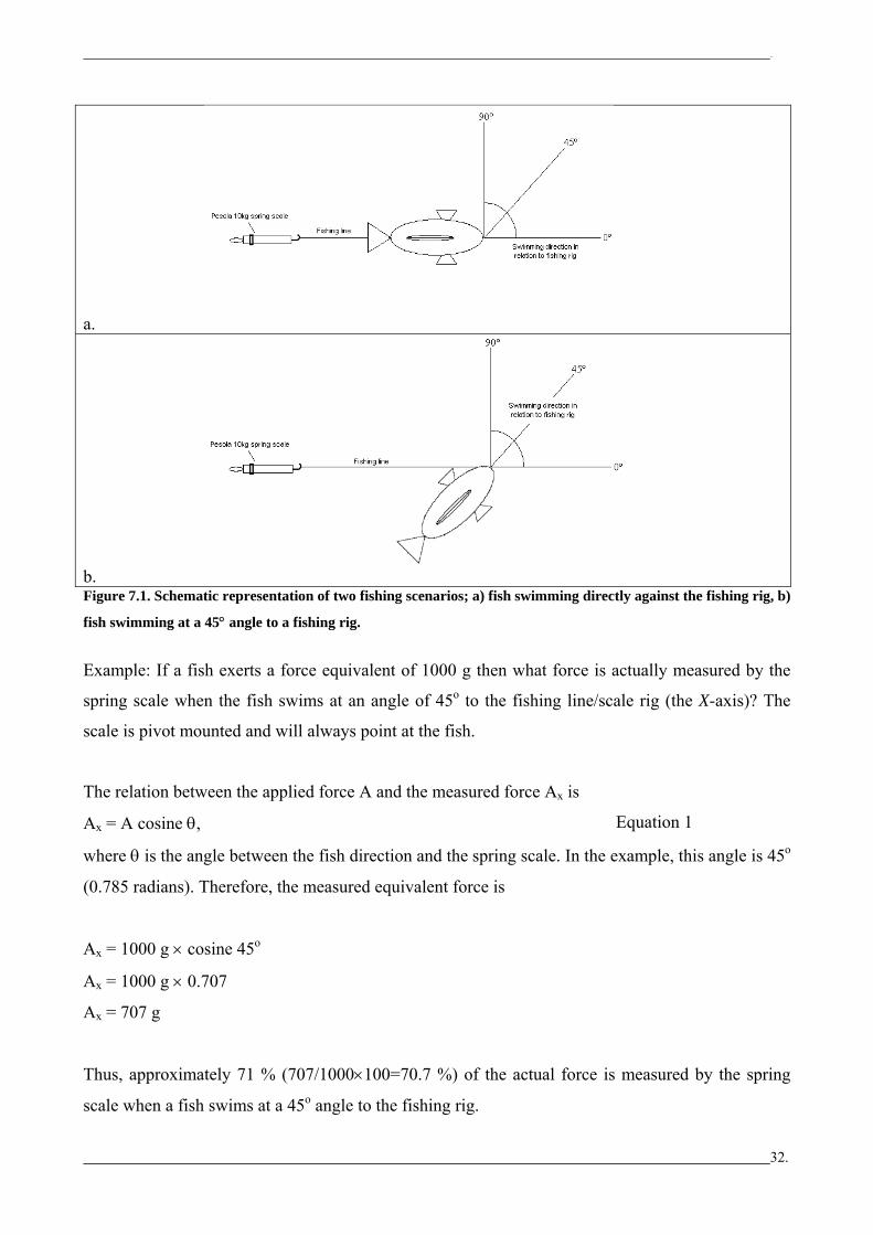
a.
b. Figure 7.1. Schematic representation of two fishing scenarios; a) fish swimming directly against the fishing rig, b)
fish swimming at a 45° angle to a fishing rig.
Example: If a fish exerts a force equivalent of 1000 g then what force is actually measured by the
spring scale when the fish swims at an angle of 45o to the fishing line/scale rig (the X-axis)? The
scale is pivot mounted and will always point at the fish.
The relation between the applied force A and the measured force Ax is
Ax = A cosine θ, Equation 1
where θ is the angle between the fish direction and the spring scale. In the example, this angle is 45o
(0.785 radians). Therefore, the measured equivalent force is
Ax = 1000 g × cosine 45o
Ax = 1000 g × 0.707
Ax = 707 g
Thus, approximately 71 % (707/1000×100=70.7 %) of the actual force is measured by the spring
scale when a fish swims at a 45o angle to the fishing rig.
32.

..
An alternative example is what force is actually applied by a fish swimming at an angle of 45o when
a force equivalent of 1000 g is measured by the spring scale? In general we solve this by
rearranging equation (1) to solve for A, giving
A = Ax /cosine θ Equation 2
In the example, Ax=1000g and θ = 45o and so solving for A gives
A = 1000g / cosine 45o
A = 1000g / 0.707
A = 1414g
A force equivalent of 1000g applied at 45o would equal an applied force of 1414 g. Thus, if a fish
swims at any angle other than 0o the measured force will be less than the applied force. Figure 8
shows the measured force as a percentage of the applied force as the angle of a swimming fish
(in relation to the fishing line/scale rig, the X-axis) increases from 0o. (This is just the cosine
function.)
0
10
20
30
40
50
60
70
80
90
100
0 10 20 30 40 50 60 70 80 90
Fish swimming angle in relation to the fishing line/scale rig (the x-axis)
% o
f for
ce re
pres
ente
d by
the
x-ax
is
Figure 8. The measured force as a percentage of the applied force as the angle of a swimming fish, in relation to
the fishing rig (the X-axis), increases from 0o
While this is a simplification of what would happen when a fish is mouth hooked and displays flight
behaviour, this example shows that we may have underestimated the maximum pushing power of
carp. If our trap gates are designed using the minimum weight (estimated from this study) that is
required to allow the force passage of the targeted size range, it is highly likely that all fish at and
above the range will be able to pass into the trap.
33.