CONCEPTUAL DESIGN OF FLIGHT VEHICLES - IARE
67
LECTURE NOTES ON CONCEPTUAL DESIGN OF FLIGHT VEHICLES Prepared by Ms. M Snigdha Assistant Professor Ms. G Swathi Assistant Professor Department of Aeronautical Engineering INSTITUTE OF AERONAUTICAL ENGINEERING (AUTONOMOUS) Dundigal, Hyderabad - 500 043
Transcript of CONCEPTUAL DESIGN OF FLIGHT VEHICLES - IARE
LECTURE NOTES
ON
CONCEPTUAL DESIGN OF FLIGHT
VEHICLES
Prepared by
Ms. M Snigdha
Assistant Professor
Ms. G Swathi
Assistant Professor
Department of Aeronautical Engineering
INSTITUTE OF AERONAUTICAL ENGINEERING (AUTONOMOUS)
Dundigal, Hyderabad - 500 043

UNIT 1
OVERVIEW OF THE DESIGN PROCESS, SIZING FROM A CONCEPTUAL SKETCH
AIRFOIL GEOMETRY SELECTION, THRUST TO WEIGHT RATIO, WING LOADING
1.1 DESIGN:
Design is a creation of plan or convention for the construction of an object or a system as in
architectural blueprints, engineering drawings, business processes, circuit diagrams and sewing
patterns.
Fig 1.1 Design Wheel
1.2 DESIGN OVERVIEW:
The aircraft is essentially a payload compartment with wings. This focus was derived from early
scoring analysis which identified system weight and aircraft loading time as the two key design
parameters. Since the aircraft must be capable of carrying a variety of payload sizes and weights,
the structure required to achieve that objective is potentially the heaviest element of the aircraft. As
the design of the payload system also has a direct impact on loading time, preliminary design
focused on the development of a fast and light weight payload system capable of meeting restraint
requirements with the minimum aerodynamic features needed to complete lap requirements for the
flight mission.
The design takes advantage of a high tensile strength fabric for the primary payload system
structure. Individual fabric pockets are attached to a central carbon-fiber spar, eliminating the need
for a structural payload bay floor. This innovative fabric payload system is enclosed by a sixty nine
inch span, twin tractor, low wing monoplane with tricycle landing gear. The aircraft sits diagonally
within the 4 ft x 5 ft plan form limits, maximizing aspect ratio and providing additional length for
the fuselage fairing, thus maximizing aerodynamic efficiency.

The aircraft utilizes mold less, foam/fiberglass/carbon-fiber composite construction for the wing,
tail and fuselage internal structure. As the external fuselage takes no structural loads, significant
weight savings were achieved by vacuum-forming a thin, foam shell designed only for
aerodynamic loads. The foam fuselage fairing has a full-length top hatch which, combined with a
low-wing, and allows rapid access to the payload. This payload-focused configuration minimizes
the key parameters of system weight and loading time through its structural efficiency and access
to payloads, while providing sufficient aerodynamic performance and propulsive power density.
1.3 DESIGN OF AN AIRCRAFT STARTS OUT IN THREE PHASES:
1.3.1 CONCEPTUAL DESIGN PHASE:
The design step involves sketching a variety of possible aircraft configurations that meet the
required design specifications. By drawing a set of configurations, designers seek to reach the
design configuration that satisfactorily meets all requirements as well as go hand in hand with
factors such as aerodynamics, propulsion, flight performance, structural and control systems.
This is called design optimization. Fundamental aspects such as fuselage shape, wing
configuration and location, engine size and type are all determined at this stage. Constraints to
design like those mentioned above are all taken into account at this stage as well. The final
product is a conceptual layout of the aircraft configuration on paper or computer screen, to be
reviewed by engineers and other designers.
Fig 1.2 Conceptual Sketch
1.3.2 PRELIMINARY DESIGN PHASE:
The design configuration arrived at in the conceptual design phase is then tweaked and
remodeled to fit into the design parameters. In this phase, wind tunnel testing and
computational fluid dynamic calculations of the flow field around the aircraft are done. Major
structural and control analysis is also carried out in this phase. Aerodynamic flaws and
structural instabilities if any are corrected and the final design is drawn and finalized. Then
after the finalization of the design lies the key decision with the manufacturer or individual
designing it whether to actually go ahead with the production of the aircraft. At this point
several designs, though perfectly capable of flight and performance, might have been opted out
of production due to their being economically nonviable.

1.3.3 DETAILED DESIGN PHASE:
This phase simply deals with the fabrication aspect of the aircraft to be manufactured. It
determines the number, design and location of ribs, spars, sections and other structural
elements. All aerodynamic, structural, propulsion, control and performance aspects have
already been covered in the preliminary design phase and only the manufacturing remains.
Flight simulators for aircraft are also developed at this stage.
Fig 1.3 Three phases of aircraft design
1.4 CONCEPTUAL DESIGN:
1.4.1 MISSION REQUIREMENTS:
As a requirement, each participating team has to simulate the delivery of an emergency
package (payload) to stranded crew of an Antarctic expedition on a blended wing/body radio
controlled transport vehicle. The aircraft can be of any configuration of a blended wing/body
and the wing aspect ratio must be greater than or equal to 2.0. The payloads to be used are four
400-gram Dick Smith’s Chicken Gravy packets each with dimension 180mm x 130mm x
40mm.The ultimate aim is to achieve highest wing loading with best payload weight-to- take-
off weight ratio.
1.4.2 TIME CONSIDERATION:
A total time allowance of 30 minutes is given to perform 3 flights, which does not include
refueling. As soon as the payloads are given, timer starts. Within 30 minutes, the team needs to

install the given payload, start the engine and complete an allocated circuit (approx. 600m per
circuit) before landing and such process is to be repeated twice more.
In order to complete the mission as quickly as possible, the following points are taken into
consideration:
1) Ease of payload accessibility
2) Height lift coefficient
3) Short take off and landing
4) Capability of rapid turn
1.5 PRELIMINARY DESIGN:
A careful look at the commercial transport jets in use, points out many common features amongst
them. Some of these are:
1) Medium bypass turbofan
This choice regarding the type of engine is due to the following reasons. 10 In the flight regime
of Mach number between 0.6-0.85, turbofans give the best efficiency and moreover reduction
in thrust output with speed is not rapid. Also, the noise generated by a medium bypass turbofan
engine is considerably low. Following this trend a medium bypass turbofan is chosen as the
power plant.
2) Wing mounted engines
Though not a rule, wing mounted engines dominate the designs of top aircraft companies like
Boeing and Airbus. Alternative designs could be adopted. But, given the experience gained
with the wing mounted engines and the large data available a configuration with two wing
mounted engines is adopted. Swept back wings and a conventional tail configuration is chosen.
Again, this choice is dictated by the fact that a large amount of data (is available) for such
configurations.
1.6 DESIGN PROJECT:
After the preliminary design has been approved by the manufacture / customer, the detailed design
studies are carried out. These include the following.
1) Wind tunnel and structural testing on models based on the preliminary design. These test serve
as a check on the correctness of the estimated characteristics and assessment of new concepts
proposed in the design.
2) Mock-up: This is a full scale model of the airplane or its important sections.
This helps in
a) Efficient lay-out of structural components and equipments.
b) Checking the clearances, firing angles of guns, visibility etc. Currently this stage can be
avoided by the use of CAD packages.
3) Complete wind tunnel testing of the approved configuration.
Currently CFD (Computational Fluid Dynamics) plays an important role in reducing the
number of test to be carried out.
4) Preparation of detailed drawings.
5) Final selection of power plant, c.g. calculations, performance & stability calculations.

6) Fabrication of prototypes. Generally six prototypes are constructed. Some of them are used for
verifying structural integrity and functioning of various systems. Others are used for flight
testing to evaluate performance and stability.
7) Pre-production manufacture and flight testing to ensure that the defects in the prototype (s)
have been corrected.
8) Series production and flight testing to meet specified operational and airworthiness
requirements.
1.7 CLASSIFICATION OF AIRPLANES:
Before discussing further about airplane design, it is helpful to know about different types of
airplane. These are classified according to
a) Purpose
b) Configuration
1.7.1 CLASSIFICATION OF AIRPLANE ACCORDING TO PURPOSE:
There are two main types of airplanes viz. civil and military.
The category of civil airplanes includes passenger, cargo, agricultural, sports and ambulance. The
category of military airplanes includes fighter, bomber, interceptor, reconnaissance, and aircraft
for logistic support like troop-carriers and rescue aircraft. Military aircraft are often designed to
cater to more than one role e.g. fighter bomber or interceptor fighter. The purpose of an airplane
dictates its specifications. For example a passenger airplane should have,
a) High level of safety
b) High payload carrying capacity
c) Economy in operation
d) Comforts
e) Ability to fly in any weather and
f) Ability to use aerodromes of respective classes
A bomber should have,
a) Long range
b) High load carrying capacity
c) High speed
d) High endurance
e) High ceiling and
f) Adequate fire protection
An interceptor should have,
a) High rate of climb
b) High ceiling (3 to 4 km above contemporary bombers)
c) High speed
d) High maneuverability
e) Ability to fly in any weather and
f) Appropriate armament
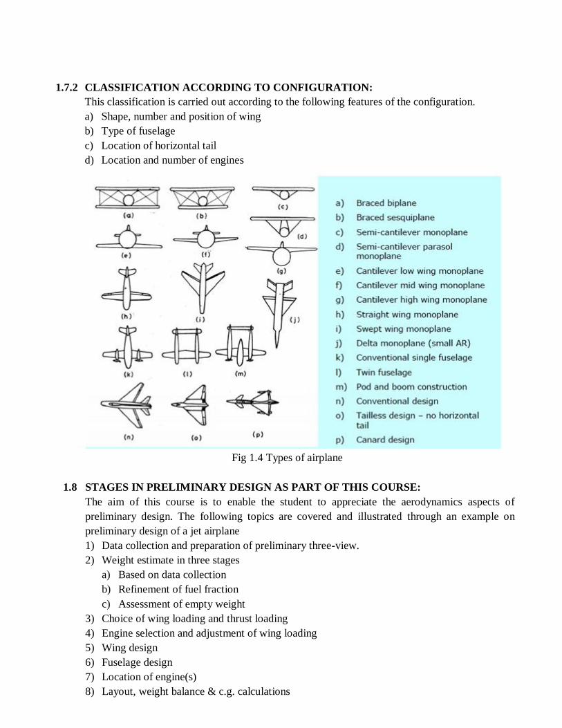
1.7.2 CLASSIFICATION ACCORDING TO CONFIGURATION:
This classification is carried out according to the following features of the configuration.
a) Shape, number and position of wing
b) Type of fuselage
c) Location of horizontal tail
d) Location and number of engines
Fig 1.4 Types of airplane
1.8 STAGES IN PRELIMINARY DESIGN AS PART OF THIS COURSE:
The aim of this course is to enable the student to appreciate the aerodynamics aspects of
preliminary design. The following topics are covered and illustrated through an example on
preliminary design of a jet airplane
1) Data collection and preparation of preliminary three-view.
2) Weight estimate in three stages
a) Based on data collection
b) Refinement of fuel fraction
c) Assessment of empty weight
3) Choice of wing loading and thrust loading
4) Engine selection and adjustment of wing loading
5) Wing design
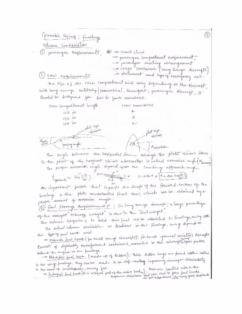
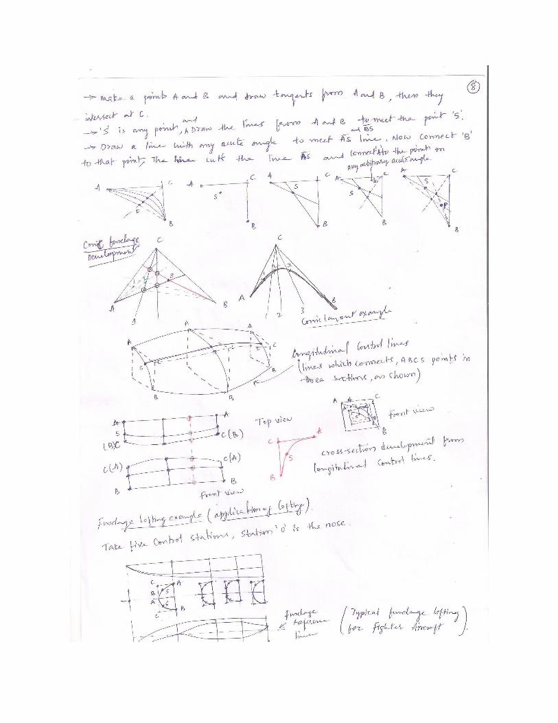
6) Fuselage design
7) Location of engine(s)
8) Layout, weight balance & c.g. calculations
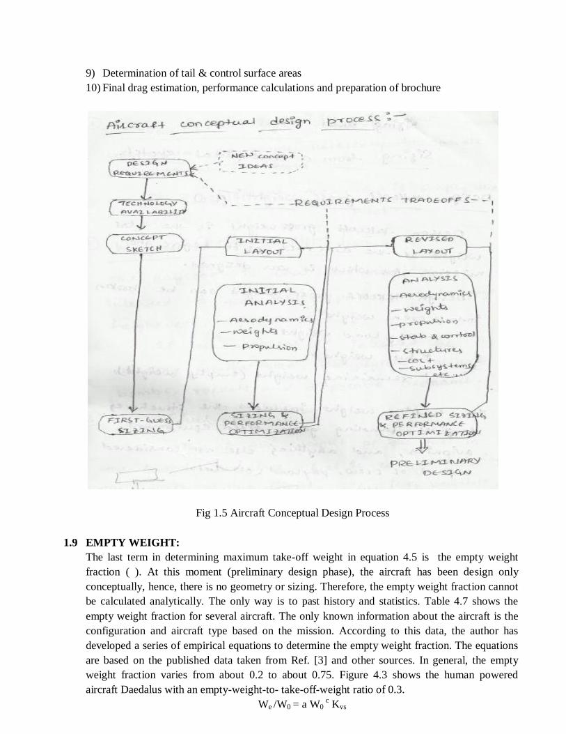
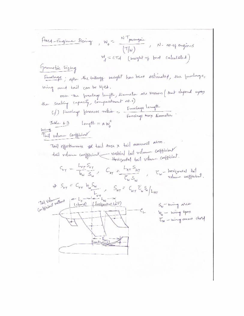
9) Determination of tail & control surface areas
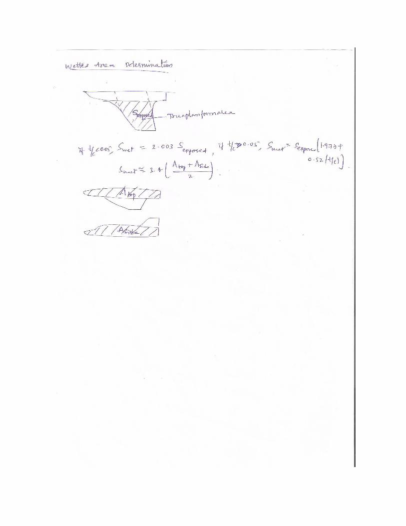
10) Final drag estimation, performance calculations and preparation of brochure
Fig 1.5 Aircraft Conceptual Design Process
1.9 EMPTY WEIGHT:
The last term in determining maximum take-off weight in equation 4.5 is the empty weight
fraction ( ). At this moment (preliminary design phase), the aircraft has been design only
conceptually, hence, there is no geometry or sizing. Therefore, the empty weight fraction cannot
be calculated analytically. The only way is to past history and statistics. Table 4.7 shows the
empty weight fraction for several aircraft. The only known information about the aircraft is the
configuration and aircraft type based on the mission. According to this data, the author has
developed a series of empirical equations to determine the empty weight fraction. The equations
are based on the published data taken from Ref. [3] and other sources. In general, the empty
weight fraction varies from about 0.2 to about 0.75. Figure 4.3 shows the human powered
aircraft Daedalus with an empty-weight-to- take-off-weight ratio of 0.3.
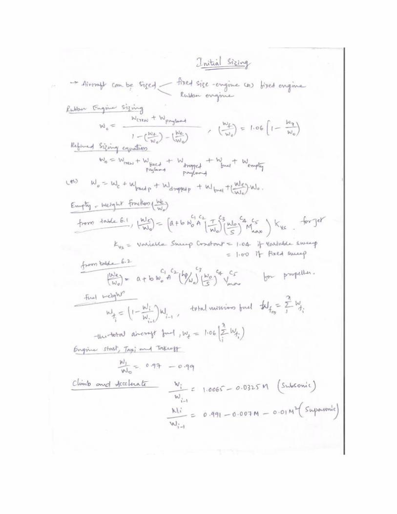
We /W0 = a W0 c Kvs
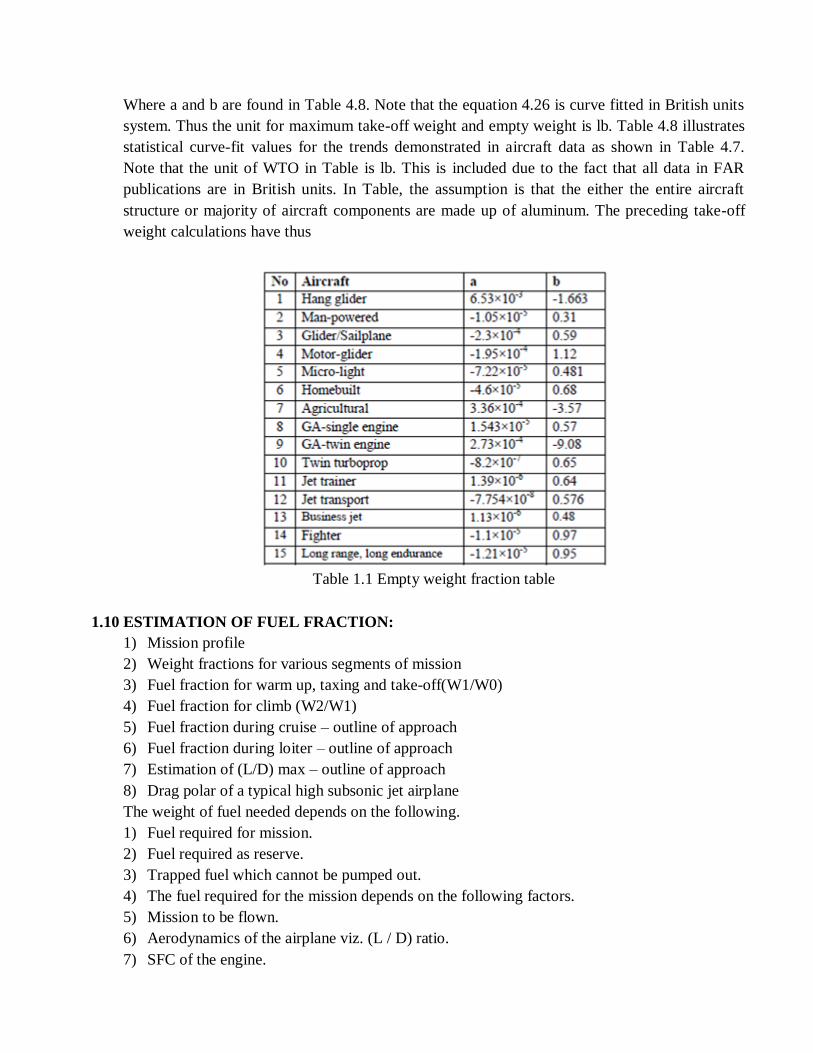
Where a and b are found in Table 4.8. Note that the equation 4.26 is curve fitted in British units
system. Thus the unit for maximum take-off weight and empty weight is lb. Table 4.8 illustrates
statistical curve-fit values for the trends demonstrated in aircraft data as shown in Table 4.7.
Note that the unit of WTO in Table is lb. This is included due to the fact that all data in FAR
publications are in British units. In Table, the assumption is that the either the entire aircraft
structure or majority of aircraft components are made up of aluminum. The preceding take-off
weight calculations have thus
Table 1.1 Empty weight fraction table
1.10 ESTIMATION OF FUEL FRACTION:
1) Mission profile
2) Weight fractions for various segments of mission
3) Fuel fraction for warm up, taxing and take-off(W1/W0)
4) Fuel fraction for climb (W2/W1)
5) Fuel fraction during cruise – outline of approach
6) Fuel fraction during loiter – outline of approach
7) Estimation of (L/D) max – outline of approach
8) Drag polar of a typical high subsonic jet airplane
The weight of fuel needed depends on the following.
1) Fuel required for mission.
2) Fuel required as reserve.
3) Trapped fuel which cannot be pumped out.
4) The fuel required for the mission depends on the following factors.
5) Mission to be flown.
6) Aerodynamics of the airplane viz. (L / D) ratio.
7) SFC of the engine.
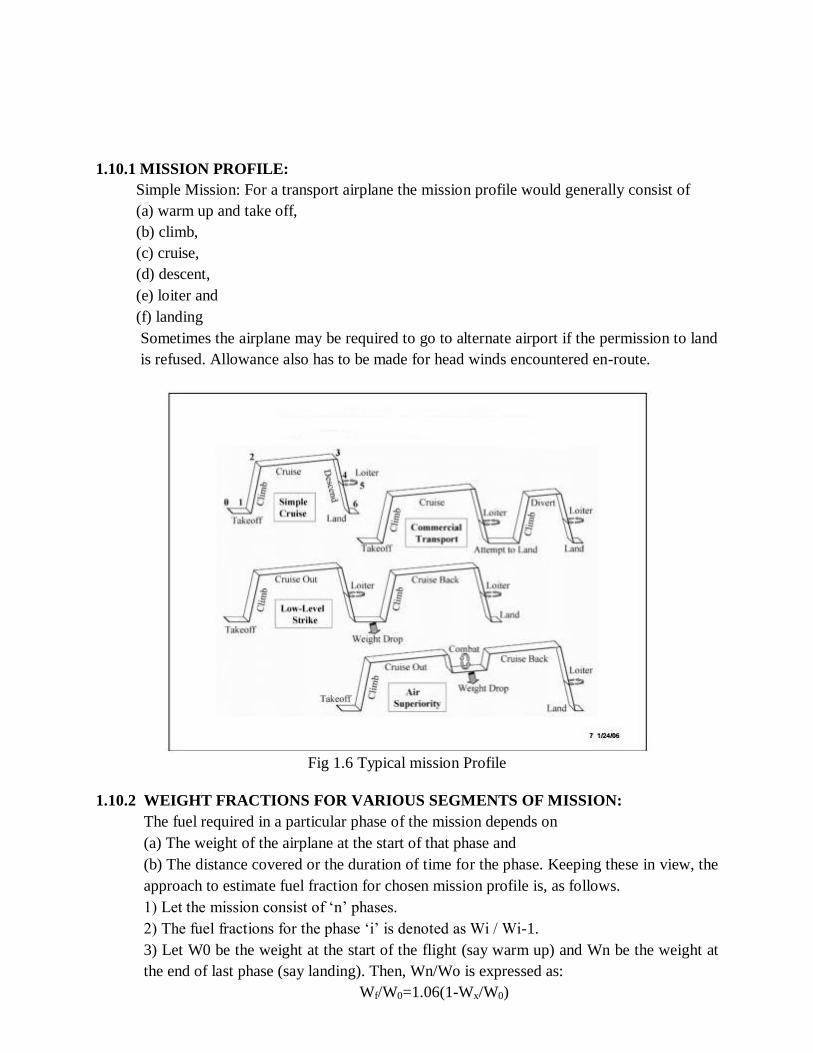
1.10.1 MISSION PROFILE:
Simple Mission: For a transport airplane the mission profile would generally consist of
(a) warm up and take off,
(b) climb,
(c) cruise,
(d) descent,
(e) loiter and
(f) landing
Sometimes the airplane may be required to go to alternate airport if the permission to land
is refused. Allowance also has to be made for head winds encountered en-route.
Fig 1.6 Typical mission Profile
1.10.2 WEIGHT FRACTIONS FOR VARIOUS SEGMENTS OF MISSION:
The fuel required in a particular phase of the mission depends on
(a) The weight of the airplane at the start of that phase and
(b) The distance covered or the duration of time for the phase. Keeping these in view, the
approach to estimate fuel fraction for chosen mission profile is, as follows.
1) Let the mission consist of ‘n’ phases.
2) The fuel fractions for the phase ‘i’ is denoted as Wi / Wi-1.
3) Let W0 be the weight at the start of the flight (say warm up) and Wn be the weight at
the end of last phase (say landing). Then, Wn/Wo is expressed as:
Wf/W0=1.06(1-Wx/W0)

1.11 FUEL FRACTION FOR WARM UP, TAXING AND TAKE-OFF (W1 / W0):
Based on the data, the rough guidelines are as follows.
For home built and single engine piston airplanes W1/W0 is 0.99. For twin engine turboprops,
jet transports (both civil and military), flying boats and supersonic airplanes W1/W0 is 0.98. For
military trainers and fighters W1/W0 is 0.97.
1.12 FUEL FRACTION FOR CLIMB (W2 / W1)
The following guidelines are given based on the data. The low speed airplanes including the
twin-engine airplanes and flying boat cruise at moderate altitude (say 4 to 6 km) and hence
W2/W1 is taken as 0.99.
The military and civil transport jets cruise around 11 km altitude and W2/W1 is taken as 0.98.
The fighter airplanes have very powerful engines and attain supersonic Mach number at the end
of the climb. In this case, W2/W1 is between 0.9-0.96. Similarly, the supersonic transport
airplanes which cruise at high altitudes (15 to 18 km), W2/W1 is around 0.9. Reference 1.15,
chapter 7 gives more elaborate procedure to estimate W2/W1 and is followed for fighter and
supersonic cruise airplanes.
1.13 FUEL FRACTION DURING CRUISE – OUTLINE OF APPROACH:
Equations (3.8) and (3.10) present the Breguet formulae for range of airplanes with engine-
propeller combination and with jet engine respectively. Consult books on performance analysis
(e.g. section 7.4.2 of Ref.3.3) for the derivation of these equations. However, it may be pointed
out that while deriving these formulae it is assumed that the following quantities remain constant
during the flight.
a) Lift coefficient.
b) Specific fuel consumption (BSFC or TSFC)
c) Propeller efficiency for airplanes with engine-propeller combination and
d) Flight altitude
Equations for range can also be derived when the flight velocity remains constant instead of the
lift coefficient.
The derivation is as follows.
In a flight at velocity V (in m/s), the distance dR (in km) covered when a quantity of fuel dWf
(in N) is consumed in time dt, is given as :
dR = dWf x (km / N of fuel) (3.27)
Now, in a time interval dt, the distance covered in km is 3.6 V dt, where V is the flight speed in
m/s; the factor 3.6 is to convert velocity to kmph. Note dt is in hrs.
Further, for jet engined airplanes the fuel consumed, dWf, in the time interval ‘dt‘ is :
dWf = TSFC x T x dt
Where T is in N, TSFC is N/N-hr or hr-1 and dt is in hrs.


UNIT 2
INTIAL SIZING, CONFIGURATION LAYOUT, CREW STATION, PASSENGERS
AND PAYLOAD
2.1 INTRODUCTION:
In the conceptual phase, it shall be estimated the trust-to-weight ratio and the wing loading
two fundamental parameters in aircraft design. This section presents and provides an interactive
methodology to estimate the best suited
1) Takeoff mass, operating empty mass, fuel mass
2) Takeoff thrust
3) Wing area and wing loading
The following parts of Loftin's method will be presented:
a) landing field length
b) takeoff field length
c) climb gradient in the 2 segment
d) climb gradient during missed approach
e) Cruise speed.
Fig 2.1 Loftin Method
2.2 SIZING METHODOLOGY:
The aim of the sizing exercise is to determine to within some limits the size and weight of the
aircraft that will meet the mission objectives and to determine overall design parameters such as
wing loading, disk loading, power required, rotor tip speed, wing aspect ratio, etc. At this stage,
details of the construction are not known so that heavy reliance is placed on statistical formulas
for component weights. Relatively simple analysis techniques are used to determine aerodynamic
characteristics such as aircraft drag, maximum lift coefficient and lift-curve slope of wings
and/or rotor blades, and stability and trim parameters. Often actual engine data (termed an engine
deck) is not available since the engine selection has not yet taken place. In such cases, data for
similar engine types is scaled to provide estimates of power or thrust available and fuel
consumption as functions of altitude, velocity and throttle settingThe overall size and shape of
the fuselage is determined by the payload. In the case of the Civil Transport Rotorcraft, the
fuselage must hold 12 (or 19) passengers and their luggage along with two flight crew. A flight
attendant is also required since the aircraft must be certified under FAR Part 25. Standards for
aisle width, seat width and pitch and pilot seat size are available and can be used to estimate the
interior dimensions of the fuselage. Decisions such as whether to place passengers two-abreast,
three-abreast or in some other arrangement need also be made. Because of the nature of the
current mission and payload, the fuselage will likely more or less resemble that of a typical
commuter aircraft rather than that of the conventional helicopter or large transport. As an
example, consider a 30‖ seat pitch and 18‖ seat width in a three-abreast configuration. The total
aisle width is 20‖. The minimum fuselage inner diameter to accomodate this interior comes out to
about 6 1 2 feet. According to Raymer, at least 2—8 inches are needed for insulation and other
space between inner wall and outer skin so that an outer diameter of 7‘ is realistic. For the 12-
passenger configuration, four rows of seats are necessary. These four rows plus additional space
for an entry door, a small galley and, perhaps, a lavatory result in 13-foot-long cabin section. The
luggage compartment will be located behind the passengers. That, enough space for the cockpit,
and tapered sections at the tail and nose will result in a fuselage length of 41 ft. The fineness
ratio (length/average diameter) of this configuration comes out to approximately 5.86, within the
range for reasonable tradeoff between pressure drag and skin-friction drag. Some guidelines for
the fuselage design include:
1) The overall fineness ratio should be at least 4.
2) The fineness ratio of the aft fuselage (converging section) should be approximately 3
with maximum upsweep angle less than 14◦.
3) The optimal fineness ratio of the nose section depends on the aircraft design Mach
number. The fineness ratio should be at least 1 regardless of Mach number. For design
Mach numbers between 0.76 and 0.9
The ideal nose fineness ratio can be obtained from:= 74.7714 M2 − 113.0765M + 43.7671
As long as the above guidelines are met, the fineness ratio should be minimized if low drag is the
only goal. Of additional primary concern is the moment arm from aircraft center of gravity to the
horizontal and vertical tail surfaces. Short moment arms lead to large tail areas in order to meet
stability and control-power requirements. Normally the minimum fineness ratio should be about
6 to ensure reasonably sized tails and control surfaces. For the 19-passenger version of the
aircraft, a fuselage ―plug‖ of about 5 ft. can be added which extends the fineness ratio to a value
of 6.57. The ―basic‖ fuselage would then have an equivalent flat-plate drag area of about 2.4 ft2
while the extended fuselage would have f ≈ 2.8 ft2. Note that these estimates are based on a
standard drag build-up method outlined in Chapter 1. Very little else about the aircraft is known
at this point. Even the fuselage weight cannot yet be determined since the loads experienced by
the fuselage structure (and therefore the weight of that structure) depend on the maximum weight
of the aircraft. Consequently, the usual next step consists of guessing–experience will often be
invoked at this time in order to guess values within reason. The objective of the succeeding
sizing exercise is to refine the design to optimal values of the parameters, originally guessed, but
now selected with conviction. The first guess to be made is of the aircraft design gross weight
(GW).


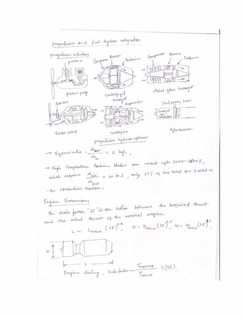
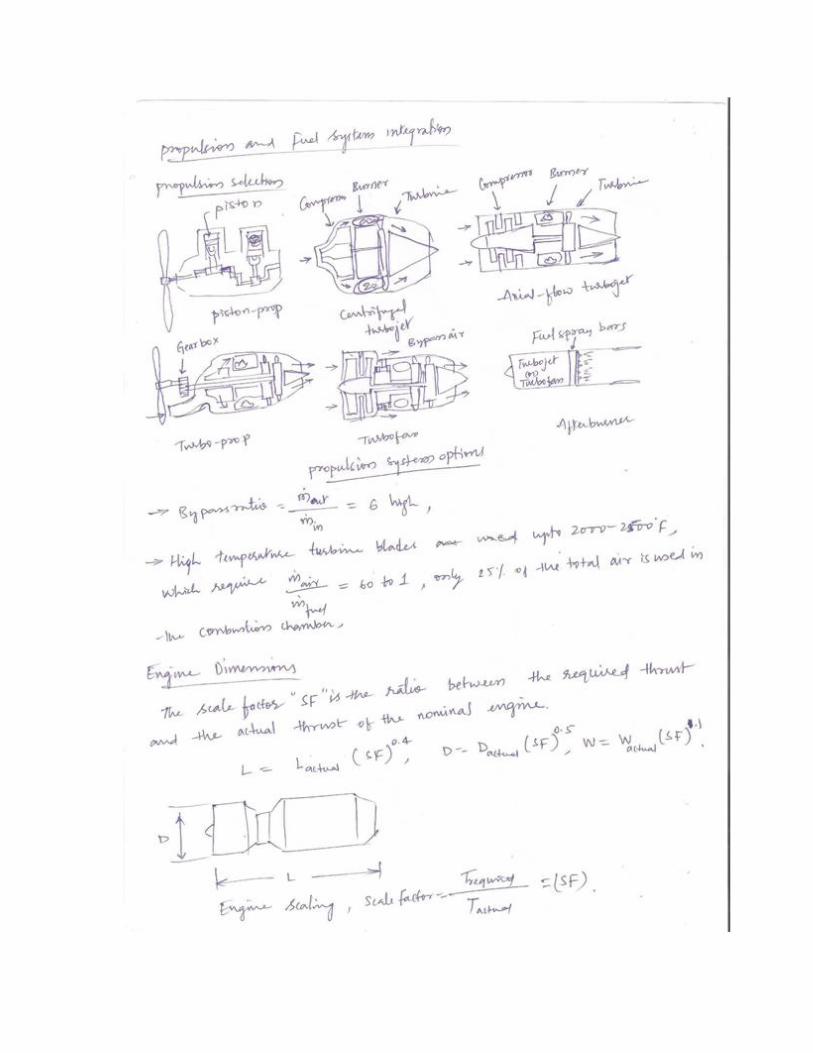
UNIT 3
PROPULSION AND FUEL SYSTEM INTEGRATION, LANDING GEAR AND
SUBSYSTEMS
3.1 ENGINE PERFORMANCE:
As a rule, engine performance (thrust or power and fuel flow vs altitude and Mach number)
should be determined using engine decks provided by the engine manufacturer. If these are not
available, calculations based on thermodynamic and gas-dynamic analysis can be used. The
guidelines given in Chapter 5 are limited, but can be used if other information is not available.
One new type of engine which has been tested but which has never been in production is the
convertible‖ engine. This power plant can act as both turbo-shaft and turbofan. The conversion
between them is enacted through a series of clutches and shutters. As a rule of thumb, the thrust
available under a set of atmospheric and operating conditions is approximately 1.2 times the
available horsepower (i.e., T (lbs) = 1.2 (lb/hp) × hp). Thus the thrust-specific fuel consumption
becomes the power-specific fuel consumption divided by 1.2. (Thrust-specific fuel consumption
has units of lbs fuel/ lb-hr.)
The landing gear in aviation is the structure that supports an aircraft on the ground and allows it
to taxi, takeoff and to land. It is a complex structure capable of reaching the largest local loads on
the aircraft. In one brief moment, the landing gear must make the best of returning the aircraft
from its natural environment to hostile environment-the earth.
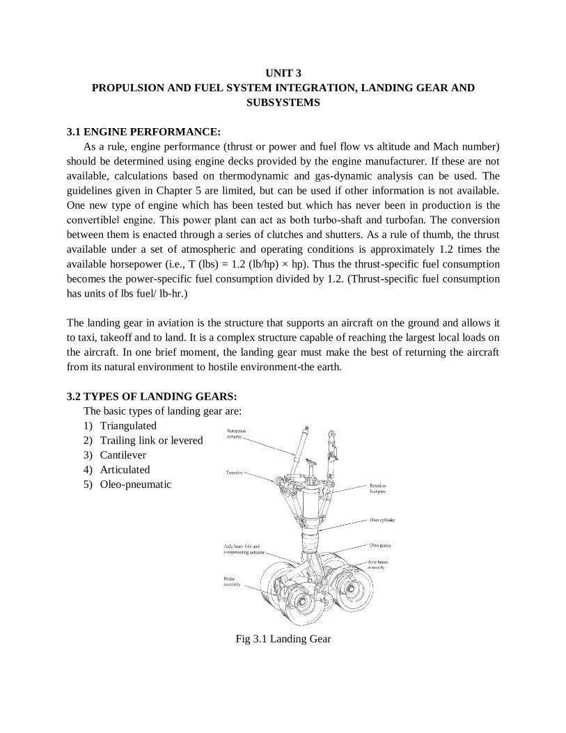
3.2 TYPES OF LANDING GEARS:
The basic types of landing gear are:
1) Triangulated
2) Trailing link or levered
3) Cantilever
4) Articulated
5) Oleo-pneumatic
Fig 3.1 Landing Gear
3.3 PURPOSE:
The purpose of landing gear is
1) To provide smooth ride and steering the aircraft on taxiing
2) To absorb kinetic shocks during landing touchdown
3) To stop the aircraft with wheel brakes during runway operation
4) Provide adequate tail down angle for takeoff rotation &
5) To provide the stable support while ground parking
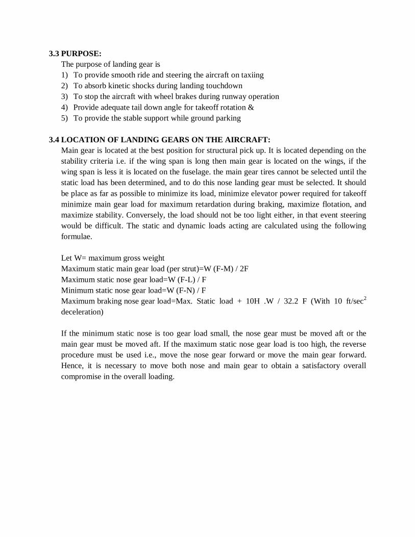
3.4 LOCATION OF LANDING GEARS ON THE AIRCRAFT:
Main gear is located at the best position for structural pick up. It is located depending on the
stability criteria i.e. if the wing span is long then main gear is located on the wings, if the
wing span is less it is located on the fuselage. the main gear tires cannot be selected until the
static load has been determined, and to do this nose landing gear must be selected. It should
be place as far as possible to minimize its load, minimize elevator power required for takeoff
minimize main gear load for maximum retardation during braking, maximize flotation, and
maximize stability. Conversely, the load should not be too light either, in that event steering
would be difficult. The static and dynamic loads acting are calculated using the following
formulae.
Let W= maximum gross weight
Maximum static main gear load (per strut)=W (F-M) / 2F
Maximum static nose gear load=W (F-L) / F
Minimum static nose gear load=W (F-N) / F
Maximum braking nose gear load=Max. Static load + 10H .W / 32.2 F (With 10 ft/sec2
deceleration)
If the minimum static nose is too gear load small, the nose gear must be moved aft or the
main gear must be moved aft. If the maximum static nose gear load is too high, the reverse
procedure must be used i.e., move the nose gear forward or move the main gear forward.
Hence, it is necessary to move both nose and main gear to obtain a satisfactory overall
compromise in the overall loading.


UNIT 4
BASELINE DESIGN- AERODYNAMICS AND PROPULSION, STRUCTURES,
WEIGHT AND BALANCES
4.1 LIFT TO DRAG RATIO:
There are several parameters that are fundamental to understanding performance. These
parameters do not necessarily improve our understanding of how or why airplanes fly but are
a useful aid to understand airplane performance. The most important aerodynamic parameter
is the lift-to-drag ratio, often referred to as L over D and written L/D. Anyone interested in
airplanes has likely heard these words at one time or another. The L/D combines lift and drag
into a single number that can be thought of as the airplane’s efficiency for flight. Since lift
and drag are both forces, L/D has no dimensions. A higher value of L/D means that the
airplane is producing lift more efficiently.
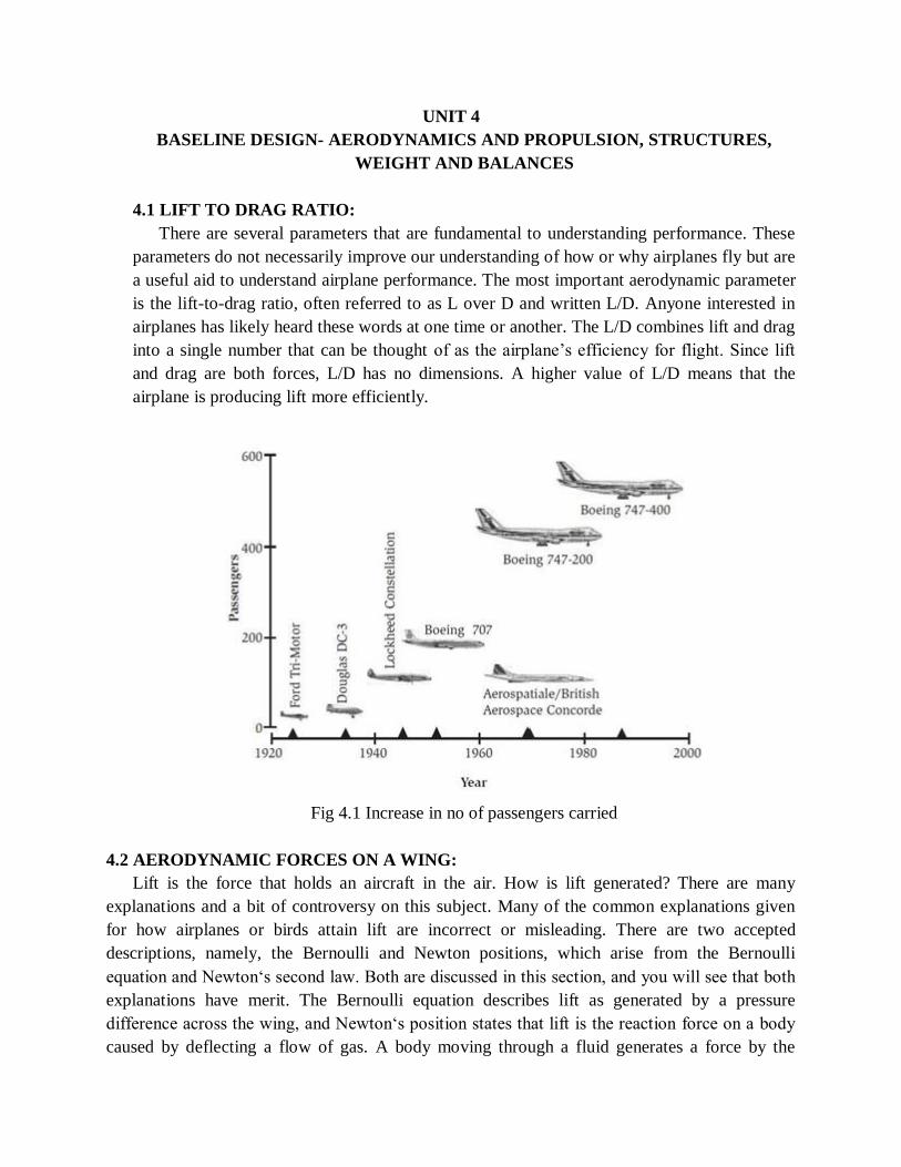
Fig 4.1 Increase in no of passengers carried
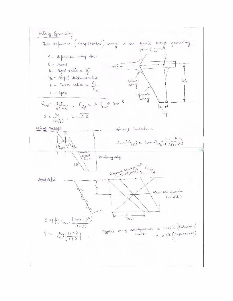
4.2 AERODYNAMIC FORCES ON A WING:
Lift is the force that holds an aircraft in the air. How is lift generated? There are many
explanations and a bit of controversy on this subject. Many of the common explanations given
for how airplanes or birds attain lift are incorrect or misleading. There are two accepted
descriptions, namely, the Bernoulli and Newton positions, which arise from the Bernoulli
equation and Newton‘s second law. Both are discussed in this section, and you will see that both
explanations have merit. The Bernoulli equation describes lift as generated by a pressure
difference across the wing, and Newton‘s position states that lift is the reaction force on a body
caused by deflecting a flow of gas. A body moving through a fluid generates a force by the
pressure variation around the body. Turning a moving fluid also generates a force on a solid
body, although you must be careful to consider the flow turning on both surfaces of an airfoil, for
otherwise an incorrect theory results.
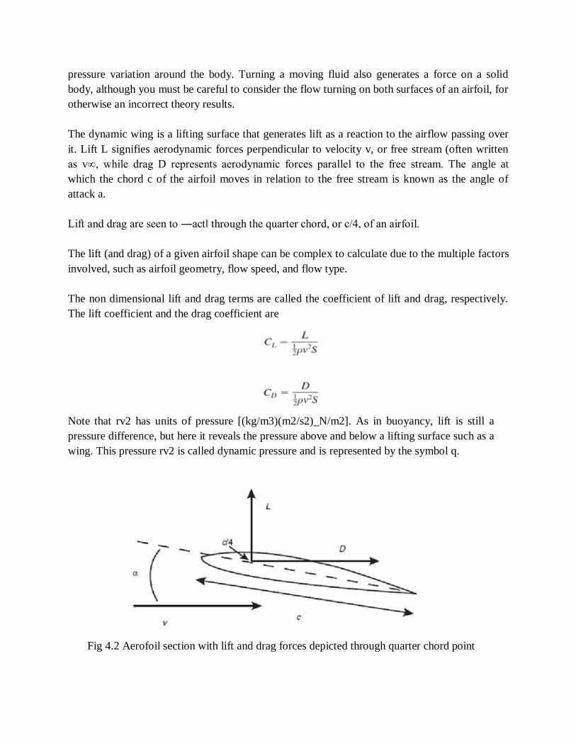
The dynamic wing is a lifting surface that generates lift as a reaction to the airflow passing over
it. Lift L signifies aerodynamic forces perpendicular to velocity v, or free stream (often written
as v∞, while drag D represents aerodynamic forces parallel to the free stream. The angle at
which the chord c of the airfoil moves in relation to the free stream is known as the angle of
attack a.
Lift and drag are seen to ―act‖ through the quarter chord, or c/4, of an airfoil.
The lift (and drag) of a given airfoil shape can be complex to calculate due to the multiple factors
involved, such as airfoil geometry, flow speed, and flow type.
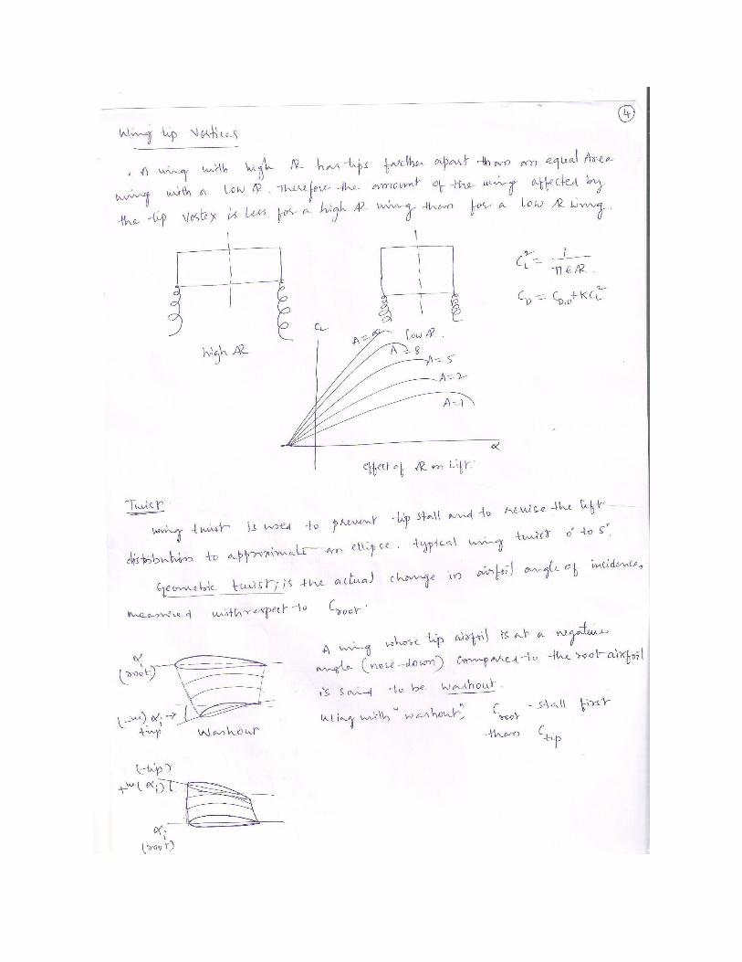
The non dimensional lift and drag terms are called the coefficient of lift and drag, respectively.
The lift coefficient and the drag coefficient are
Note that rv2 has units of pressure [(kg/m3)(m2/s2)_N/m2]. As in buoyancy, lift is still a
pressure difference, but here it reveals the pressure above and below a lifting surface such as a
wing. This pressure rv2 is called dynamic pressure and is represented by the symbol q.
Fig 4.2 Aerofoil section with lift and drag forces depicted through quarter chord point

4.3 V-n DIAGRAM:
Fig 4.3 V-n Diagram
4.4 MANEUVER DIAGRAM:
This diagram illustrates the variation in load factor with airspeed for maneuvers. At low
speeds the maximum load factor is constrained by aircraft maximum CL. At higher speeds the
maneuver load factor may be restricted as specified by FAR Part 25.
The maximum maneuver load factor is usually +2.5 . If the airplane weighs less than 50,000 lbs.,
however, the load factor must be given by: n= 2.1 + 24,000 / (W+10,000) n need not be greater
than 3.8. This is the required maneuver load factor at all speeds up to Vc, unless the maximum
achievable load factor is limited by stall.
The negative value of n is -1.0 at speeds up to Vc decreasing linearly to 0 at VD. Maximum
elevator deflection at VA and pitch rates from VA to VD must also be considered.
4.5 GUST DIAGRAM:
Loads associated with vertical gusts must also be evaluated over the range of speeds.
The FAR's describe the calculation of these loads in some detail. Here is a summary of the
method for constructing the V-n diagram. Because some of the speeds (e.g. VB) are determined
by the gust loads, the process may be iterative. Be careful to consider the alternative
specifications for speeds such as VB.

The gust load may be computed from the expression given in FAR Part 25. This formula is
the result of considering a vertical gust of specified speed and computing the resulting change
in lift. The associated incremental load factor is then multiplied by a load alleviation factor
that accounts primarily for the aircraft dynamics in a gust.
4.6 MATERIAL SELECTION:
The basic question is how do we go about selecting a material for a given part? This may seem
like a very complicated process until we realize than we are often restrained by choices we have
already made. For example, if different parts have to interact then material choice becomes
limited. When we talk about choosing materials for a component, we take into account many
different factors. These factors can be broken down into the following areas.
1) Material Properties
a) The expected level of performance from the material
2) Material Cost and Availability.
a) Material must be priced appropriately (not cheap but right)
b) Material must be available (better to have multiple sources)
3) Processing
a) Must consider how to make the part,
b) for example: Casting, Machining, Welding
4) Environment
a) The effect that the service environment has on the part
b) The effect the part has on the environment
c) The effect that processing has on the environment
5) Kinds of Materials.
a) Iron
b) Aluminum
c) Copper
d) Magnesium
e) Composites
f) Ceramics
g) Glass
h) Semi-conductors
i) Structural ceramics (SiN, SiC)
j) Refractory Composites
k) Polymers
l) Rubber
m) Plastics

UNIT 5
BASELINE DESIGN- STABILITY AND CONTROL, PERFORMANCE AND
CONSTRAINY ANALYSIS
5.1 INTRODUCTION:
The final design of horizontal and vertical tails requires calculation of the dynamic stability
and response of the airplane in cases like:
(a) Different flight conditions
(b) Different weights and c.g. locations and
(c) Possible variations in configuration.
The topics dealt with in this chapter are based on the following two observations.
1) For conventional subsonic airplanes, if the airplane has adequate level of static stability,
then it would have reasonable dynamic stability.
2) If the areas of the control surfaces are adequate to trim the airplane (i.e. bring the
moments about the three airplane axes to zero) in certain critical conditions, then the
airplane would have reasonable level of controllability.
5.2 NEUTRAL POINT:
It is known that the c.g. of the airplane moves during the flight. Further, the contribution of
wing to Cmα depends sensitively on the location of the c.g. When the c.g. moves aft, xcg
increases and the wing contribution becomes less and less negative or more and more positive.
There is a c.g. location at which (Cmα)stick-fixed becomes zero. This location of c.g. is called
the stick-fixed neutral point. In this case, the airplane is neutrally stable. The location of the
neutral point can be obtained by putting Cmα = 0.
It is noted that the contribution of tail to (Cmα) changes when the stick is fixed or free. It may be
recalled, from course on stability analysis, that in stick-free case, the elevator is free to move
about its hinge.
5.3: PERFORMANCE ESTIMATION:
After carrying out the stability analysis, the major dimensions of the airplane have been
arrived at. This will enable preparation of the revised three view drawing. Using this drawing
and the flight conditions, a drag polar of the airplane can be estimated.
The performance analysis includes the following:
1) The variation of stalling speed (Vs) at various altitudes
2) Variations with altitude of maximum speed (Vmax) and minimum speed from power
output consideration (Vmin) power. The minimum speed of the airplane at an altitude

will be the higher of Vs and (Vmin) power. The maximum speed and minimum speed
will decide the flight envelope.
3) Variations with altitude of the maximum rate of climb ((R/C)max) and maximum angle
of climb (γmax) ; the flight being treated as steady climb. Variations with altitude of
V(R/C)max and Vγmax. To arrive at these quantities choose a set of altitudes and at
each of these altitudes, obtain the R/C and γ at different flight velocities. From the plot
of (R/C)max vs. h, the values of absolute ceiling and service ceiling can be obtained. At
absolute ceiling (R/C)max is zero and at service ceiling (R/C)max is 30 m/min. For
multi-engined airplanes, the rate of climb with one engine inoperative must satisfy the
airworthiness regulations.
4) To arrive at the cruising speed and altitude, choose a range of altitudes around the
cruising altitude mentioned in the specifications. At each of these altitudes obtain the
range in constant velocity flights choosing different velocities. The information on
appropriate values of specific fuel consumption (SFC) can be obtained from the engine
charts. The values of range obtained at different speeds and altitudes be plotted as range
vs velocity curves with altitude as parameter. Draw an envelope of this curves.The
altitude and velocity at which the range is maximum can be considered as the cruising
speed (Vcruise) and cruising altitude (hcruise). These curves also give information
about the range of flight speeds and altitudes around Vcruise and hcruise at which near
optimum performance is obtained.
5) The maximum rate of turn (max ψ ) and the minimum radius of turn (rmin) in steady
level turn depend on the thrust available,CLmax and the permissible load factor (nmax).
The value of CLmax used here is that without the flaps. For high speed airplanes the
value of C Lmax depends also on Mach number. The value of nmax depends on the
weight and the type of airplane. Choose a set of altitudes and at each of these altitudes
obtain the values of Vψ max and Vrmin. From plots of these quantities obtain
variations, with altitude, of rmin, and Vrmin.
6) Take - off run and take - off distance: During take-off an airplane accelerates on the
ground. For an airplane with nose wheel type of landing gear, around a speed of 85% of
the take-off speed, the pilot pulls the stick back. Then, the airplane attains the angle of
attack corresponding to take-off and the airplane leaves the ground. The point at which
the main wheels leave the ground is called the unstick point and the distance from the
start of take-off point to the unstick point is called the ground run. After the unstick, the
airplane goes along a curved path as lift is more than the weight. This phase of take-off
is called transition at the end of which the airplane climbs along a straight line. The
take-off phase is said to be over when the airplane attains screen height which is
generally 15 m above the ground. The horizontal distance from the start of the take off
to the where the airplane attains screen height is called take off distance (Fig.3.4). The
take off run and the take-off distance can be estimated by writing down equations of
motion in different phases.

7) Landing Distance: The landing flight begins when the airplane is at the screen height at a
velocity called the approach speed. During the approach phase the airplane descends
along a flight path of about 3 degrees. Subsequently the flight path becomes horizontal in
the phase called ‗flare‘. In this phase the pilot also tries to touch the ground gently. The
point where the main wheels touch the ground is called touchdown point. Subsequent to
touch down, the airplane rolls along the ground for about 3 seconds during which the
nose wheel touches the ground. This phase is called free roll. After this phase the brakes
are applied and the airplane comes to halt. In some airplanes, thrust in the reverse
direction is produced by changing the direction of jet exhaust or by reversible pitch
propeller. In some airplanes, the drag is increased by speed brakes, spoilers or parachutes.
For airplanes which land on the deck of the ship, an arresting gear is employed to reduce
the landing distance. The horizontal distance from the start of approach at screen height
till the airplane comes to rest is called landing distance.
5.4 BALANCED FIELD LENGTH:
It is the length of the run way required from, consideration of safety in the event of engine
failure. If the engine fails soon after the aircraft begins to roll, the pilot can stop the airplane
without difficulty. If the engine fails when the airplane is near the unstick point, then he should
not have difficulty in completing the take-off. The speed of the airplane, during take-off, at
which the distance to stop after an engine failure equals the distance to continue the takeoff on
the remaining engine (s) is called a decision speed. The balanced field length is the take-off
distance to clear the screen height when one engine fails at the decision speed. Subsection 4.8.1
can be referred to for estimating the balance field length.
Remarks:
1) The landing distance is considerably affected by piloting techniques. To take into
account the uncertainty, the landing distance is multiplied by 1.67 to get the
FAR/EASA(European Air Safety Agency) landing distance.
2) Take-off and landing distance calculations are repeated assuming different altitudes of
air fields and different atmospheric conditions e.g. A + 200 C i.e. the sea level
temperature is 350 C instead of 150 C in the standard atmosphere.
5.5 GENERAL REMARKS ON PERFORMANCE ESTIMATION:
5.5.1 OPERATING ENVELOPE:
The maximum speed and minimum speed can be calculated from the level flight analysis.
However, the attainment of maximum speed may be limited by other considerations. The
operating envelope for an airplane is the range of flight speeds permissible at different altitudes.
5.5.2 ENERGY HEIGHT TECHNIQUE FOR CLIMB PERFORMANCE:
The analysis of a steady climb shows that the velocity corresponding to maximum rate of
climb (V(R/C) max) increases with altitude. Consequently, climb with (R/C) max involves

acceleration and the rate of climb will actually be lower than that given by the steady climb
analysis. This is because a part of the engine output would be used to increase the kinetic
energy.
Secondly, the aim of the climb is to start from velocity near Vtake-off and at htake-off and
attain a velocity near Vcruise at hcruise.
5.5.3 RANGE PERFORMANCE:
For commercial airplanes the range performance is of paramount importance. Hence,
range performance with different amounts of payload and fuel on board the airplane, needs to
be worked out. In this context the following three limitations should to be considered.
a) MAXIMUM PAYLOAD:
The number of seats and the size of the cargo compartment are limited. Hence maximum
payload capacity is limited.
b) MAXIMUM FUEL:
The size of the fuel tanks depends on the space in the wing and the fuselage to store the
fuel. Hence, there is limit on the maximum amount of fuel that can be carried by the
airplane.
c) MAXIMUM TAKE-OFF WEIGHT:
The airplane structure is designed for a certain load factor and maximum takeoff weight.

5.6 CASE STUDIES AND DESIGN OF UNIQUE AIRCRAFT CONCEPTS:
5.6.1 DC 1:
Development of the DC-1 can be traced back to the 1931 crash of TWA Flight 599, which
was caused by a Fokker F.10 Trimotor airliner suffering a structural failure of one of its wings,
probably due to water which had over time seeped between the layers of the wood laminate and
dissolved the glue holding the layers together. Following the accident, the Aeronautics Branch of
the U.S. Department of Commerce placed stringent restrictions on the use of wooden wings on
passenger airliners. Boeing developed an answer, the 247, a twin-engined all-metal monoplane
with a retractable undercarriage, but their production capacity was reserved to meet the needs of
United Airlines, part of United Aircraft and Transport Corporation which also owned Boeing.
TWA needed a similar aircraft to respond to competition from the Boeing 247 and they asked
five manufacturers to bid for construction of a three-engined, 12-seat aircraft of all-metal
construction, capable of flying 1,080 mi (1,740 km) at 150 mph (242 km/h). The most
demanding part of the specification was that the airliner would have to be capable of safely
taking off from any airport on TWA's main routes (and in particular Albuquerque, at high
altitude and with severe summer temperatures) with one engine non-functioning.
Fig 5.1 DC 1
Donald Douglas was initially reluctant to participate in the invitation from TWA. He doubted
that there would be a market for 100 aircraft, the number of sales necessary to cover
development costs. Nevertheless, he submitted a design consisting of an all-metal, low-wing,
twin-engined aircraft seating 12 passengers, a crew of two and a flight attendant. The aircraft
exceeded the specifications of TWA even with two engines. It was insulated against noise,
heated, and fully capable of both flying and performing a controlled takeoff or landing on one
engine.

Don Douglas stated in a 1935 article on the DC-2 that the first DC-1 cost $325,000 to design and
build.
5.6.2 DC 2:
In the early 1930s, fears about the safety of wooden aircraft structures (responsible for the
crash of a Fokker Trimotor) compelled the American aviation industry to develop all-metal
types. The United Aircraft and Transport Corporation had a monopoly on the Boeing 247; rival
Transcontinental and Western Air issued a specification for an all-metal trimotor.
The Douglas response was more radical. When it flew on July 1, 1933, the prototype DC-1 had a
robust tapered wing, retractable landing gear, and two 690 hp (515 kW) Wright radial engines
driving variable-pitch propellers. It seated 12 passengers.
Fig 5.2 DC 2
TWA accepted the basic design and ordered twenty DC-2s having more powerful engines and a
bit more length, to carry 14 passengers in a 66-inch-wide cabin. The design impressed American
and European airlines and further orders followed. Those for European customers KLM, LOT,
Swissair, CLS and LAPE were assembled by Fokker in the Netherlands after that company
bought a licence from Douglas.Airspeed Ltd. took a similar licence for DC-2s to be delivered in
Britain and assigned the company designation Airspeed AS.23, but although a registration for
one aircraft was reserved none were actually delivered. Another licence was taken by the
Nakajima Aircraft Company in Japan; unlike Fokker and Airspeed, Nakajima built five aircraft
as well as assembling at least one Douglas-built aircraft. A total of 130 civil DC-2s were built
with another 62 for the United States military. In 1935 Don Douglas stated in an article that the
DC-2 cost about $80,000 per aircraft if mass-produced.
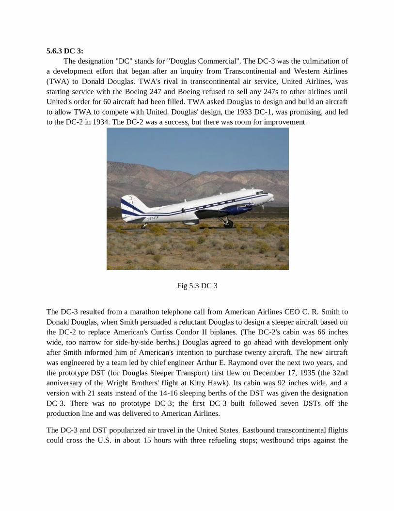
5.6.3 DC 3:
The designation "DC" stands for "Douglas Commercial". The DC-3 was the culmination of
a development effort that began after an inquiry from Transcontinental and Western Airlines
(TWA) to Donald Douglas. TWA's rival in transcontinental air service, United Airlines, was
starting service with the Boeing 247 and Boeing refused to sell any 247s to other airlines until
United's order for 60 aircraft had been filled. TWA asked Douglas to design and build an aircraft
to allow TWA to compete with United. Douglas' design, the 1933 DC-1, was promising, and led
to the DC-2 in 1934. The DC-2 was a success, but there was room for improvement.
Fig 5.3 DC 3
The DC-3 resulted from a marathon telephone call from American Airlines CEO C. R. Smith to
Donald Douglas, when Smith persuaded a reluctant Douglas to design a sleeper aircraft based on
the DC-2 to replace American's Curtiss Condor II biplanes. (The DC-2's cabin was 66 inches
wide, too narrow for side-by-side berths.) Douglas agreed to go ahead with development only
after Smith informed him of American's intention to purchase twenty aircraft. The new aircraft
was engineered by a team led by chief engineer Arthur E. Raymond over the next two years, and
the prototype DST (for Douglas Sleeper Transport) first flew on December 17, 1935 (the 32nd
anniversary of the Wright Brothers' flight at Kitty Hawk). Its cabin was 92 inches wide, and a
version with 21 seats instead of the 14-16 sleeping berths of the DST was given the designation
DC-3. There was no prototype DC-3; the first DC-3 built followed seven DSTs off the
production line and was delivered to American Airlines.
The DC-3 and DST popularized air travel in the United States. Eastbound transcontinental flights
could cross the U.S. in about 15 hours with three refueling stops; westbound trips against the

wind took 171⁄2 hours. A few years earlier such a trip entailed short hops in slower and shorter-
range aircraft during the day, coupled with train travel overnight
A variety of radial engines were available for the DC-3. Early-production civilian aircraft used
Wright R-1820 Cyclone 9s, but later aircraft (and most military versions) used the Pratt &
Whitney R-1830 Twin Wasp which gave better high-altitude and single engine performance.
Three DC-3S Super DC-3s with Pratt & Whitney R-2000 Twin Wasps were built in the late
1940s.
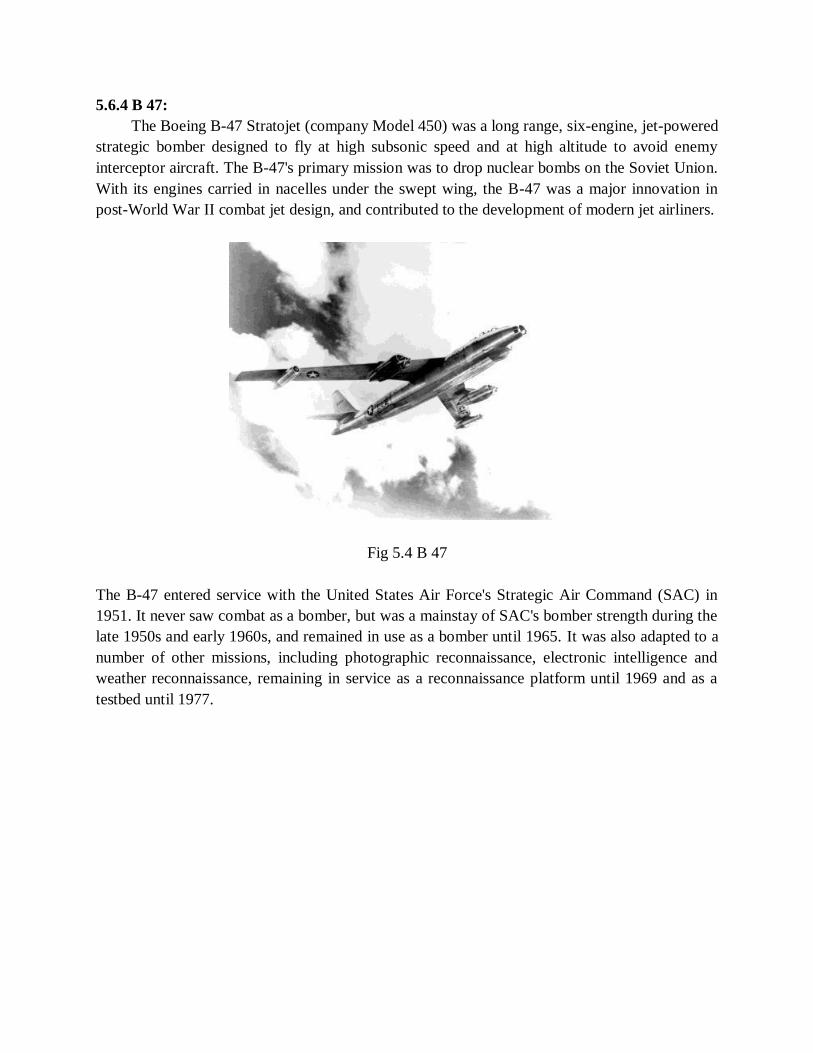
5.6.4 B 47:
The Boeing B-47 Stratojet (company Model 450) was a long range, six-engine, jet-powered
strategic bomber designed to fly at high subsonic speed and at high altitude to avoid enemy
interceptor aircraft. The B-47's primary mission was to drop nuclear bombs on the Soviet Union.
With its engines carried in nacelles under the swept wing, the B-47 was a major innovation in
post-World War II combat jet design, and contributed to the development of modern jet airliners.
Fig 5.4 B 47
The B-47 entered service with the United States Air Force's Strategic Air Command (SAC) in
1951. It never saw combat as a bomber, but was a mainstay of SAC's bomber strength during the
late 1950s and early 1960s, and remained in use as a bomber until 1965. It was also adapted to a
number of other missions, including photographic reconnaissance, electronic intelligence and
weather reconnaissance, remaining in service as a reconnaissance platform until 1969 and as a
testbed until 1977.
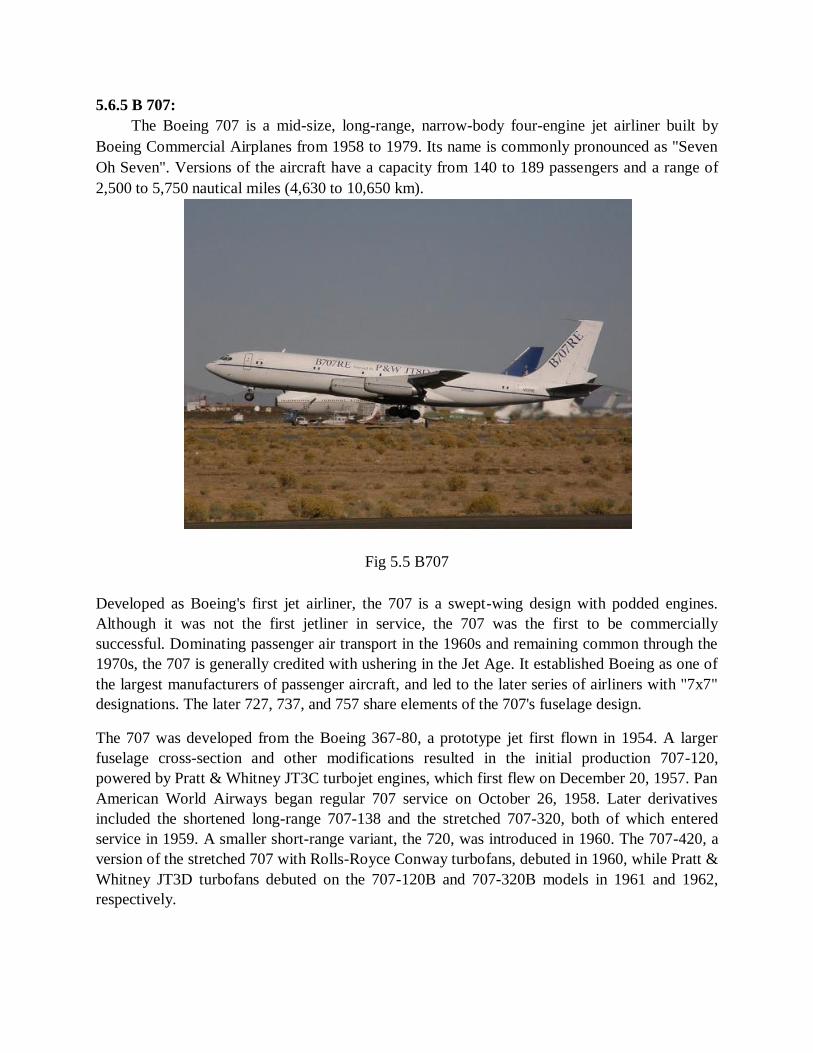
5.6.5 B 707:
The Boeing 707 is a mid-size, long-range, narrow-body four-engine jet airliner built by
Boeing Commercial Airplanes from 1958 to 1979. Its name is commonly pronounced as "Seven
Oh Seven". Versions of the aircraft have a capacity from 140 to 189 passengers and a range of
2,500 to 5,750 nautical miles (4,630 to 10,650 km).
Fig 5.5 B707
Developed as Boeing's first jet airliner, the 707 is a swept-wing design with podded engines.
Although it was not the first jetliner in service, the 707 was the first to be commercially
successful. Dominating passenger air transport in the 1960s and remaining common through the
1970s, the 707 is generally credited with ushering in the Jet Age. It established Boeing as one of
the largest manufacturers of passenger aircraft, and led to the later series of airliners with "7x7"
designations. The later 727, 737, and 757 share elements of the 707's fuselage design.
The 707 was developed from the Boeing 367-80, a prototype jet first flown in 1954. A larger
fuselage cross-section and other modifications resulted in the initial production 707-120,
powered by Pratt & Whitney JT3C turbojet engines, which first flew on December 20, 1957. Pan
American World Airways began regular 707 service on October 26, 1958. Later derivatives
included the shortened long-range 707-138 and the stretched 707-320, both of which entered
service in 1959. A smaller short-range variant, the 720, was introduced in 1960. The 707-420, a
version of the stretched 707 with Rolls-Royce Conway turbofans, debuted in 1960, while Pratt &
Whitney JT3D turbofans debuted on the 707-120B and 707-320B models in 1961 and 1962,
respectively.
The 707 has been used on domestic, transcontinental and transatlantic flights, and for cargo and
military applications. A convertible passenger-freighter model, the 707-320C, entered service in
1963, and passenger 707s have been modified to freighter configurations. Military derivatives
include the E-3 Sentry airborne reconnaissance aircraft and the C-137 Stratoliner VIP transports.
Boeing produced and delivered 1,011 airliners including the smaller 720 series; over 800 military
versions were also produced. There were 10 Boeing 707s in commercial service in July 2013.
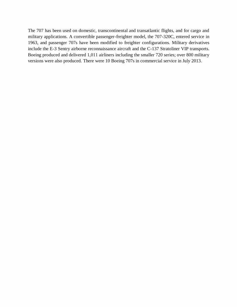
5.6.6 GENERAL DYNAMICS F 16:
The General Dynamics (now Lockheed Martin) F-16 Fighting Falcon is a single-engine
multirole fighter aircraft originally developed by General Dynamics for the United States Air
Force (USAF). Designed as an air superiority day fighter, it evolved into a successful all-weather
multirole aircraft. Over 4,500 aircraft have been built since production was approved in 1976.
Although no longer being purchased by the U.S. Air Force, improved versions are still being
built for export customers. In 1993, General Dynamics sold its aircraft manufacturing business to
the Lockheed Corporation, which in turn became part of Lockheed Martin after a 1995 merger
with Martin Marietta.
Fig 5.6 F 16
The Fighting Falcon has key features including a frameless bubble canopy for better visibility,
side-mounted control stick to ease control while maneuvering, a seat reclined 30 degrees to
reduce the effect of g-forces on the pilot, and the first use of a relaxed static stability/fly-by-wire
flight control system helps to make it a nimble aircraft. The F-16 has an internal M61 Vulcan
cannon and 11 locations for mounting weapons and other mission equipment. The F-16's official
name is "Fighting Falcon", but "Viper" is commonly used by its pilots, due to a perceived
resemblance to a viper snake as well as the Battlestar Galactica Colonial Viper starfighter.
In addition to active duty U.S. Air Force, Air Force Reserve Command, and Air National Guard
units, the aircraft is also used by the USAF aerial demonstration team, the U.S. Air Force
Thunderbirds, and as an adversary/aggressor aircraft by the United States Navy. The F-16 has
also been procured to serve in the air forces of 25 other nations.

5.6.7 SR 71 BLACK BIRD:
The Lockheed SR-71 "Blackbird" is a long-range, Mach 3+ strategic reconnaissance
aircraft that was operated by the United States Air Force. It was developed as a black project
from the Lockheed A-12 reconnaissance aircraft in the 1960s by Lockheed and its Skunk Works
division. Renowned American aerospace engineer Clarence "Kelly" Johnson was responsible for
many of the design's innovative concepts. During reconnaissance missions, the SR-71 operated
at high speeds and altitudes to allow it to outrace threats. If a surface-to-air missile launch was
detected, the standard evasive action was simply to accelerate and outfly the missile. The SR-71
was designed to have basic stealth characteristics and served as a precursor to future stealth
aircraft.
Fig 5.7 SR 71 BLACK BIRD
The SR-71 served with the U.S. Air Force from 1964 to 1998. A total of 32 aircraft were built;
12 were lost in accidents, but none lost to enemy action. The SR-71 has been given several
nicknames, including Blackbird and Habu. Since 1976, it has held the world record for the fastest
air-breathing manned aircraft, a record previously held by the YF-12.
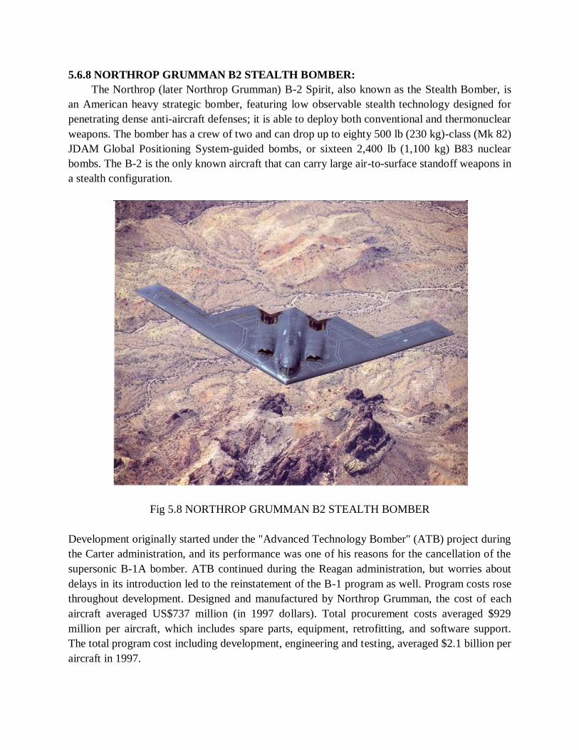
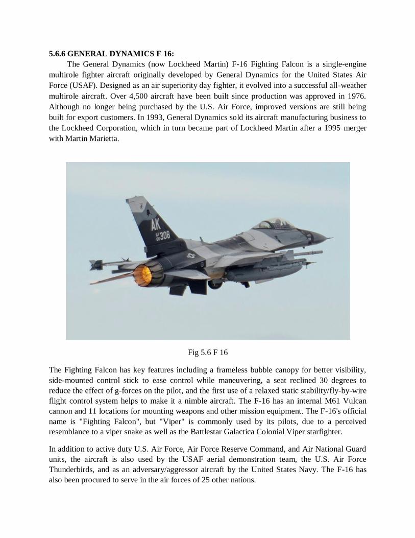
5.6.8 NORTHROP GRUMMAN B2 STEALTH BOMBER:
The Northrop (later Northrop Grumman) B-2 Spirit, also known as the Stealth Bomber, is
an American heavy strategic bomber, featuring low observable stealth technology designed for
penetrating dense anti-aircraft defenses; it is able to deploy both conventional and thermonuclear
weapons. The bomber has a crew of two and can drop up to eighty 500 lb (230 kg)-class (Mk 82)
JDAM Global Positioning System-guided bombs, or sixteen 2,400 lb (1,100 kg) B83 nuclear
bombs. The B-2 is the only known aircraft that can carry large air-to-surface standoff weapons in
a stealth configuration.
Fig 5.8 NORTHROP GRUMMAN B2 STEALTH BOMBER
Development originally started under the "Advanced Technology Bomber" (ATB) project during
the Carter administration, and its performance was one of his reasons for the cancellation of the
supersonic B-1A bomber. ATB continued during the Reagan administration, but worries about
delays in its introduction led to the reinstatement of the B-1 program as well. Program costs rose
throughout development. Designed and manufactured by Northrop Grumman, the cost of each
aircraft averaged US$737 million (in 1997 dollars). Total procurement costs averaged $929
million per aircraft, which includes spare parts, equipment, retrofitting, and software support.
The total program cost including development, engineering and testing, averaged $2.1 billion per
aircraft in 1997.
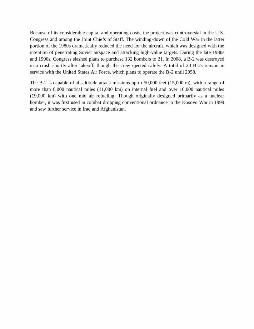
Because of its considerable capital and operating costs, the project was controversial in the U.S.
Congress and among the Joint Chiefs of Staff. The winding-down of the Cold War in the latter
portion of the 1980s dramatically reduced the need for the aircraft, which was designed with the
intention of penetrating Soviet airspace and attacking high-value targets. During the late 1980s
and 1990s, Congress slashed plans to purchase 132 bombers to 21. In 2008, a B-2 was destroyed
in a crash shortly after takeoff, though the crew ejected safely. A total of 20 B-2s remain in
service with the United States Air Force, which plans to operate the B-2 until 2058.
The B-2 is capable of all-altitude attack missions up to 50,000 feet (15,000 m), with a range of
more than 6,000 nautical miles (11,000 km) on internal fuel and over 10,000 nautical miles
(19,000 km) with one mid air refueling. Though originally designed primarily as a nuclear
bomber, it was first used in combat dropping conventional ordnance in the Kosovo War in 1999
and saw further service in Iraq and Afghanistan.