Concepts and Principles of Compositional Safety Case Construction
45
COMSA/2001/1/1 Concepts and Principles of Compositional Safety Case Construction Cover + iv + 41 pages May 2001 Dr T P Kelly COMSA/2001/1/1
Transcript of Concepts and Principles of Compositional Safety Case Construction

COMSA/2001/1/1
Concepts and Principles of
Compositional Safety Case
Construction
Cover + iv + 41 pages
May 2001
Dr T P Kelly
COMSA/2001/1/1

COMSA/2001/1/1
Page ii of iv
Executive summary
Whilst the move towards Integrated Modular Avionics (IMA) offers potential benefits of improved flexibility in function allocation, reduced development costs and improved maintainability, it poses significant problems in certification. The traditional approach to certification relies heavily upon a system being statically defined as a complete entity and the corresponding (bespoke) system safety case being constructed. However, a principal motivation behind IMA is that there is through-life (and potentially run-time) flexibility in the system configuration. An IMA system can support many possible mappings of the functionality required to the underlying computing platform.
Traditional approaches to certification of avionics systems as a statically defined configuration of components could significantly reduce the benefits of IMA by associating a large certification overhead with any module update or addition. A more promising approach is to attempt to establish a modular, compositional, approach to constructing safety cases that has a correspondence with the modular structure of the underlying architecture. As with systems architecture it would need to be possible to establish interfaces between the modular elements of the safety justification such that safety case elements may be safely composed, removed and replaced. Similarly, as with systems architecture, it will be necessary to establish the safety argument infrastructure required in order to support such modular reasoning (e.g. an infrastructure argument regarding partitioning being required in order to enable independent reasoning concerning the safety of two system elements).
By adopting a modular, compositional, approach to safety case construction it may be possible to:
• Justifiably limit the extent of safety case modification and revalidation required following anticipated system changes
• Support (and justify) extensions and modifications to a ‘baseline’ safety case
• Establish a family of safety case variants to justify the safety of a system in different configurations.
This report establishes the mechanisms for managing and representing safety cases as a composition of safety case modules. Having defined the concept of a modularised safety case, the report also examines how modularised safety case architectures can be defined, including principles for their definition and evaluation. An example generic modular safety case architecture for Integrated Modular Avionics (IMA) based systems is presented as a means of illustrating the concepts defined.
Acknowledgement This report was funded under the MOD Corporate Research Programme "Enabling the certification of novel systems"

COMSA/2001/1/1
Page iii of iv
Contents
Executive summary ii
Contents iii
List of Figures iv
1 Introduction 1
2 Safety Case Modules 1
3 Safety Case Module Composition 3
4 Representing Safety Case Modules 4
5 Interface Definition with GSN Safety Case Modules 9
6 Module Composition with GSN Modules 10
7 Safety Case Module ‘Contracts’ 13
8 Safety Case Architecture 14
9 Managing Changes to a Modular Safety Case 16
10 Evaluation of Safety Case Architecture 18
11 Modularised Generic IMA Safety Argument 22
Configuration Dependent Argument Modules 23
12 Implications for Certification Processes 29
13 Summary 30
14 References 30
Appendix B: Goal to Module Mapping 32

COMSA/2001/1/1
Page iv of iv
List of Figures
Figure 1 – Required Elements of a Safety Case Module Interface 2
Figure 2 – Principal Elements of the Goal Structuring Notation 4
Figure 3 – GSN Elements Introduced to Handle Modularity 5
Figure 4 – Use of 'Away Goals' as Argument Support 5
Figure 5 – Use of 'Away' Goals to replace Justification 6
Figure 6 – Use of 'Away' Goals as Argument Backing 6
Figure 7 – Representing Safety Case Modules and Module References in GSN 7
Figure 8 – Example Safety Argument Module View 8
Figure 9 – Use of 'Away' Context and 'Away' Solutions 8
Figure 10 – Required Elements of a Safety Case Module Interface 9
Figure 11 – The Published Interface of a GSN Safety Case Module 10
Figure 12 – The Steps Involved in Safety Case Module Composition 11
Figure 13 – Format of Contract Between Safety Case Modules 13
Figure 14 – Safety Case Architecture employing an abstraction layer 15
Figure 15 – Illustration of argument structure of DAL to SIL ‘Abstraction’ Layer Module 15
Figure 16 – A Process for Safety Case Change Management 17
Figure 17 – Activities in a SAAM Analysis 19
Figure 18 – A Simple Safety Case Architecture 20
Figure 19 – Illustration of Local Change 21
Figure 20 – Illustration of Non-Local Change 21
Figure 21 – Illustration of Architectural Change 21
Figure 22 – Safety Case Architecture of Modularised IMA Safety Argument 24
Figure 23 – Illustration of Safety Case Partitioning 25
Figure 24 – Influences affecting the independence of items (from ENV 50129) 27

COMSA/2001/1/1 Page 1 of 41
1 Introduction
Whilst the move towards Integrated Modular Avionics (IMA) offers potential benefits of improved flexibility in function allocation, reduced development costs and improved maintainability, it poses significant problems in certification. The traditional approach to certification relies heavily upon a system being statically defined as a complete entity and the corresponding (bespoke) system safety case being constructed. However, a principal motivation behind IMA is that there is through-life (and potentially run-time) flexibility in the system configuration. An IMA system can support many possible mappings of the functionality required to the underlying computing platform.
In constructing a safety case for IMA an attempt could be made to enumerate and justify all possible configurations within the architecture. However, this approach is infeasibly expensive for all but a small number of processing units and functions. Another approach is to establish the safety case for a specific configuration within the architecture. However, this nullifies the benefit of flexibility in using an IMA solution and will necessitate the development of completely new safety cases for future modifications or additions to the architecture.
A more promising approach is to attempt to establish a modular, compositional, approach to constructing safety cases that has a correspondence with the modular structure of the underlying architecture. As with systems architecture it would need to be possible to establish interfaces between the modular elements of the safety justification such that safety case elements may be safely composed, removed and replaced. Similarly, as with systems architecture, it will be necessary to establish the safety argument infrastructure required in order to support such modular reasoning (e.g. an infrastructure argument regarding partitioning being required in order to enable independent reasoning concerning the safety of two system elements).
By adopting a modular, compositional, approach to safety case construction it may be possible to:
• Justifiably limit the extent of safety case modification and revalidation required following anticipated system changes
• Support (and justify) extensions and modifications to a ‘baseline’ safety case
• Establish a family of safety case variants to justify the safety of a system in different configurations.
2 Safety Case Modules
A conventional safety case can be considered as consisting of the following four elements:
• Objectives – the safety requirements that must be addressed to assure safety
• Argument – showing how the evidence indicates compliance with the requirements
• Evidence – information from study, analysis and test of the system in question
• Context – identifying the basis of the argument presented
Defining a safety case ‘module’ involves defining the objectives, evidence, argument and context associated with one aspect of the safety case. Assuming a top-down progression of objectives-argument-evidence, safety cases can be partitioned into modules both horizontally and vertically:

Page 2 of 41 COMSA/2001/1/1
• Vertical (Hierarchical) Partitioning - The claims of one safety argument can be thought of as objectives for another. For example, the claims regarding software safety made within a system safety case can serve as the objectives of the software safety case.
• Horizontal Partitioning - One argument can provide the assumed context of another. For example, the argument that “All system hazards have been identified” can be the assumed context of an argument that “All identified system hazards have been sufficiently mitigated”.
In defining a safety case module it is essential to identify the ways in which the safety case module depends upon the arguments, evidence or assumed context of other modules. A safety case module, should therefore be defined by the following interface:
1. Objectives addressed by the module
2. Evidence presented within the module
3. Context defined within the module
4. Arguments requiring support from other modules
Inter-module dependencies:
5. Reliance on objectives addressed elsewhere
6. Reliance on evidence presented elsewhere
7. Reliance on context defined elsewhere
Figure 1 – Required Elements of a Safety Case Module Interface
Principally, the interface must specify the safety argument objectives being addressed by a module. For example, the interface for a safety argument module for a specific piece of functionality must describe clearly the safety claims that are supported for the functionality. It is crucial that the interface also exposes items 2 and 3 of the interface shown above in order to ensure that when modules are composed together they form a consistent whole. Firstly, the module must define the pieces of supporting evidence that are used in support of the module argument. When modules are composed with others, it is necessary to check that this evidence is consistent with that used in the other modules (e.g. that the models and assumptions embedded in a piece of safety analysis are not contradicted by the models and assumptions of another piece of safety analysis). Context defines the bounds and limitations of the argument presented within the module. Context could be defined at any number of points during the safety argument within a module, e.g. to define the assumed operational context, interface with other systems, assumed duration and frequency of operation or acceptability / tolerability criteria. All such context must be exposed at the boundary interface of the module in order to ensure that in composition of modules the collective context is consistent.
The argument within a safety case may not fully address all of the objectives (safety claims) of the module. There may remain claims requiring support from other modules (as yet unknown). For example, part of a software safety argument may rest upon a claim regarding the reliability of input sensors. As this is a hardware systems issue it should fall to another module to support such a claim. Under Item 4 of the interface proposed above, all argument claims remaining to be supported are required to be defined.

COMSA/2001/1/1 Page 3 of 41
Items 5-7 of the interface definition recognise that there will be times within a specific safety case module when the argument may depend upon the claims, evidence or context defined within another (known) module. For example, within a software safety argument the justification of developing the software to a specific level of integrity may depend upon the existence (claim) of an effective hardware interlock – addressed as part of the hardware argument presented in another module. Where such explicit cross-references exist they should be highlighted within the definition of the safety case module interface. This is strongly analogous to declaring the ‘use’ relationships that exist between software modules where one module is known to require the services of another module.
The principal need for having such well-defined interfaces for each safety case module arises from being able to ensure that modules are being used consistently and correctly in their target application context (i.e. when composed with other modules). This topic is addressed in the following section.
3 Safety Case Module Composition
Safety case modules can be usefully composed if their objectives and arguments complement each other – i.e. one or more of the objectives supported by a module match one or more of the arguments requiring support in the other. For example, the software safety argument is usefully composed with the system safety argument if the software argument supports one or more of objectives set by the system argument. At the same time, an important side-condition it that the evidence and assumed context of one module is consistent with that presented in the other. For example, the operational usage context assumed within the software safety argument must be consistent with that put forward within the system level argument.
The definition of safety case module interfaces and satisfaction of conditions across interfaces upon composition is analogous to the long established rely-guarantee approach to specifying the behaviour of software modules. Jones in [1] talks of ‘rely’ conditions that express the assumptions that can be made about the interrelations (interference) between operations and ‘guarantee’ conditions that constrain the end-effect assuming that the ‘rely’ conditions are satisfied. For a safety case module, the rely conditions can be thought of items 4 to 7 of the interface introduced in the previous section whilst item 1 (objectives addressed) define the guarantee conditions. Items 2 (evidence presented) and 3 (context defined) must continue to hold (i.e. not be contradicted by inconsistent evidence or context) during composition of modules.
Later in the report section 7 returns to the topic of module composition and defines the concrete steps involved in combining modules expressed in terms of the representations introduced in the following two sections.

Page 4 of 41 COMSA/2001/1/1
4 Representing Safety Case Modules
The Goal Structuring Notation (GSN) [2] - a graphical argumentation notation - explicitly represents the individual elements of any safety argument (requirements, claims, evidence and context) and (perhaps more significantly) the relationships that exist between these elements (i.e. how individual requirements are supported by specific claims, how claims are supported by evidence and the assumed context that is defined for the argument). The principal symbols of the notation are shown in Figure 2 (with example instances of each concept).
System cantolerate single
componentfailures
Sub-systemsare independent
Argument byelimination of all
hazards
Fault Treefor Hazard
H1A/J
Goal Solution StrategyAssumption /Justification
All IdentifiedSystem Hazards
Context
Undeveloped Goal(to be developed)
Developed Goal
ChildGoal
Child Goal
ParentGoal
ChoiceUninstantiated Context
Figure 2 – Principal Elements of the Goal Structuring Notation
The principal purpose of a goal structure is to show how goals (claims about the system) are successively broken down into sub-goals until a point is reached where claims can be supported by direct reference to available evidence (solutions). As part of this decomposition, using the GSN it is also possible to make clear the argument strategies adopted (e.g. adopting a quantitative or qualitative approach), the rationale for the approach (assumptions, justifications) and the context in which goals are stated (e.g. the system scope or the assumed operational role). For further details on GSN see [2]
GSN has been widely adopted by safety-critical industries for the presentation of safety arguments within safety cases. However, to date GSN has largely been used for arguments that can be defined in one place as a single artefact rather than as a series of modularised interconnected arguments. The following subsections describe how GSN can be extended to explicitly represent interrelated modules of safety case argument.
4.1 Module and ‘Away Goal’ GSN Extensions
The first extension the GSN to represent modular safety cases is a representation of modules themselves. This is required, for example, in order to be able to represent a module as providing the solution for a goal. For this purpose, the package notation from the Unified Modelling Language (UML) standard has been adopted. The new GSN symbol for safety case module is shown in Figure 3 (Right Hand Side). The Module Identifier should be a unique identifier for the module (e.g. ‘NonInterferenceArg’). The Module Description should be a succinct Noun-Phrase description of the module (e.g. “Application Non Interference Argument Module”).

COMSA/2001/1/1 Page 5 of 41
As has already discussed, in presenting a modularised argument it is necessary to be able to refer to goals (claims) satisfied within other modules. Figure 1 (left hand side) introduces a new element to the GSN for this purpose – the “Away Goal”. An away goal is a goal that is not supported within the module where it is presented but is instead supported in another module. The Module Identifier (shown at the bottom of the away goal next to the module symbol) should show the unique reference to the module where support for the goal can be found. As for ‘normal’ goals, Goal Identifier should provide a unique identifier for the goal (e.g. ‘AppAccSafe’), Goal Statement should form a Noun-Phrase Verb-Phrase prepositional statement (e.g. ‘The application is acceptably safe’).
<Module Identifier>
<Goal Statement>
<Goal Identifier>
<Module Description>
<Module Identifier>
Figure 3 – GSN Elements Introduced to Handle Modularity
Away goals can be used to provide support for the argument within a module, e.g. supporting a goal (as shown in Figure 4 left-hand side) or supporting an argument strategy (as shown in Figure 4 right-hand side). However, support for an away goal should not be shown for any module other that referred to be the away goal module reference.
<Goal Identifier><Goal Statement>
<Module Identifier>
<Goal Statement>
<Goal Identifier>
<Module Identifier>
<Goal Statement>
<Goal Identifier>
<StrategyStatement>
<Strategy
Figure 4 – Use of 'Away Goals' as Argument Support
Away Goals can also be used as a more expressive form of the existing GSN element – justification. GSN justifications are used whenever there is need to justify the nature of the safety argument being presented (e.g. justify the use of a specific failure rate figure within a goal or justify the use of a certain argument strategy). Figure 5 (left hand side) shows an example use of the existing GSN Justification symbol to provide backing for the use of a read-across approach within a component reliability argument. The drawback of this approach is that often the justification statement can be worthy of an argument in its own right yet there is no means of expressing that, although it is not a topic to be expanded at the point of citation, the argument is addressed within another part (module) of the argument. Figure 5 (right hand side) illustrates how an away goal can be used as context for the strategy to make to provide the same support but allowing reference to the module ‘ReadAcrossArgs’ where a supporting argument for this statement can be found.
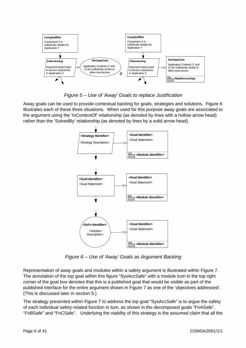
Page 6 of 41 COMSA/2001/1/1
CompSuffRel
Component X issufficiently reliable forApplication Y
Argument based uponin-service experiencein Application Z
InServiceArg
J
SimAppCtxts
Application Contexts (Y andZ) are sufficiently similar to
allow read-across
CompSuffRel
Component X issufficiently reliable forApplication Y
Argument based uponin-service experiencein Application Z
InServiceArg
ReadAcrossArgs
Application Contexts (Y andZ) are sufficiently similar toallow read-across
SimAppCtxts
Figure 5 – Use of 'Away' Goals to replace Justification
Away goals can be used to provide contextual backing for goals, strategies and solutions. Figure 6 illustrates each of these three situations. When used for this purpose away goals are associated to the argument using the ‘InContextOf’ relationship (as denoted by lines with a hollow arrow head) rather than the ‘SolvedBy’ relationship (as denoted by lines by a solid arrow head).
<Module Identifier>
<Goal Statement>
<Goal Identifier>
<Strategy Description>
<Strategy Identifier>
<Goal Identifier>
<Goal Statement>
<Module Identifier>
<Goal Statement>
<Goal Identifier>
<Module Identifier>
<Goal Statement>
<Goal Identifier>
<SolutionDescription>
<Sol'n Identifier>
Figure 6 – Use of 'Away' Goals as Argument Backing
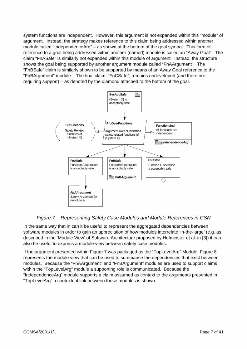
Representation of away goals and modules within a safety argument is illustrated within Figure 7. The annotation of the top goal within this figure “SysAccSafe” with a module icon in the top right corner of the goal box denotes that this is a published goal that would be visible as part of the published interface for the entire argument shown in Figure 7 as one of the ‘objectives addressed’. (This is discussed later in section 5.)
The strategy presented within Figure 7 to address the top goal “SysAccSafe” is to argue the safety of each individual safety-related function in turn, as shown in the decomposed goals “FnASafe”, “FnBSafe” and “FnCSafe”. Underlying the viability of this strategy is the assumed claim that all the
COMSA/2001/1/1 Page 7 of 41
system functions are independent. However, this argument is not expanded within this “module” of argument. Instead, the strategy makes reference to this claim being addressed within another module called “IndependenceArg” – as shown at the bottom of the goal symbol. This form of reference to a goal being addressed within another (named) module is called an “Away Goal”. The claim “FnASafe” is similarly not expanded within this module of argument. Instead, the structure shows the goal being supported by another argument module called “FnAArgument”. The “FnBSafe” claim is similarly shown to be supported by means of an Away Goal reference to the “FnBArgument” module. The final claim, “FnCSafe”, remains undeveloped (and therefore requiring support) – as denoted by the diamond attached to the bottom of the goal.
Argument over all identifiedsafety related functions of{System X}
ArgOverFunctions
IndependenceArg
All functions areindependent
FunctionsInd
FnASafeFunction A operationis acceptably safe
FnBArgument
Function B operationis acceptably safe
FnBSafe
Safety Argument forFunction A
FnAArgument
Function C operationis acceptably safe
FnCSafe
Safety Relatedfunctions of {System X}
SRFunctions
SysAccSafe
{System X} isacceptably safe
Figure 7 – Representing Safety Case Modules and Module References in GSN
In the same way that in can it be useful to represent the aggregated dependencies between software modules in order to gain an appreciation of how modules interrelate ‘in-the-large’ (e.g. as described in the ‘Module View’ of Software Architecture proposed by Hofmeister et al. in [3]) it can also be useful to express a module view between safety case modules.
If the argument presented within Figure 7 was packaged as the “TopLevelArg” Module, Figure 8 represents the module view that can be used to summarise the dependencies that exist between modules. Because the “FnAArgument” and “FnBArgument” modules are used to support claims within the “TopLevelArg” module a supporting role is communicated. Because the “IndependenceArg” module supports a claim assumed as context to the arguments presented in “TopLevelArg” a contextual link between these modules is shown.

Page 8 of 41 COMSA/2001/1/1
Top Level System XSafety Argument
TopLevelArg
FunctionalIndependenceArgument
IndependenceArg
Function A SafetyArgument
FnAArgumentFunction B SafetyArgument
FnBArgument
Figure 8 – Example Safety Argument Module View
In a safety case module view, such as that illustrated in Figure 8, it is important to recognise that the presence of a ‘SolvedBy’ relationship between modules A & B implies that there exists at least goal within module A that is supported by an argument within module B. Similarly, the existence of an ‘InContextOf’ relationship between modules A & B implies that there exists at least one contextual reference within module A to an element of the argument within module B.
4.2 ‘Away Context’ and ‘Away Solution’ GSN Extensions
Although perhaps less obviously required, there will be times in the construction of modular safety cases where it become necessary to be able to make reference from the argument of one safety case module to defined context and evidence that exists within the boundary of another. For this purpose, in a similar vein to the ‘away goal’ concept, there must additionally be ‘away’ contexts and ‘away’ solutions within the notation. Figure 9 illustrates the use of these two extensions.
SysAccSafe (Top){System X} isacceptably safe
Risk argument overall identified hazards
ArgOverIdHazards
ProcessArgs
{System X} hazardshave beenexhaustively identifed
HazExhaustIdent
All identified hazardsfor {System X}
IdentHazards
HazARiskAccRisk associated withHazard A is acceptable
HazBRiskAccRisk associated withHazard B is acceptable
OperationalEvidence for Haz A
Occurence Rate
OpEvidence
OpArgs
Accident Sequencefor Hazard A
HazAAccSeq
AccSeqs
Figure 9 – Use of 'Away' Context and 'Away' Solutions
As with away goals, away contexts (e.g. ‘IdentHazards’ in the figure) and away solutions (e.g.’OpEvidence’ in the figure) are augmented with references to the safety case modules where

COMSA/2001/1/1 Page 9 of 41
these items can be located (shown at the bottom of the context or solution symbol next to the module icon). In all other respects their use within goal structures is as for conventional context and solution references.
5 Interface Definition with GSN Safety Case Modules
The safety case module interface introduced in section 2 can be re-stated in the following manner for modules represented using the extended GSN:
1. Goals addressed by the module
2. Solution presented within the module
3. Context defined within the module
4. Goals requiring support from other modules
Inter-module dependencies:
5. Away Goal references
6. Away Solution references
7. Away Context references
Figure 10 – Required Elements of a Safety Case Module Interface
Using this definition of a safety case interface the argument represented in Figure 7 packaged as a safety case module would have a module interface as defined in the following table (Table 1)
Argument Module: TopLevelArg
Identifier Summary Module
Goals Addressed SysAccSafe {System X} is acceptably safe
Solutions Presented None
Context defined SRFunctions {System X} Safety Related Functions
Goals requiring Support FnCSafe Function C is acceptably safe
FunctionsInd All functions are independent IndepdenceArgument
FnASafe Function A is acceptably safe FnAArg
Goals
FnBSafe Function B is acceptably safe FnBArg
Solutions None
Inter-module dependencies
Context None
Table 1 – Interface for Safety Case Module “TopLevelArg”
Page 10 of 41 COMSA/2001/1/1
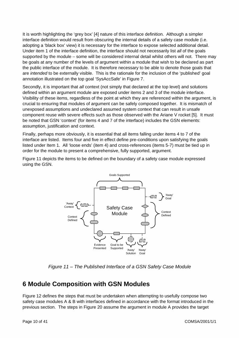
It is worth highlighting the ‘grey box’ [4] nature of this interface definition. Although a simpler interface definition would result from obscuring the internal details of a safety case module (i.e. adopting a ‘black box’ view) it is necessary for the interface to expose selected additional detail. Under item 1 of the interface definition, the interface should not necessarily list all of the goals supported by the module – some will be considered internal detail whilst others will not. There may be goals at any number of the levels of argument within a module that wish to be declared as part the public interface of the module. It is therefore necessary to be able to denote those goals that are intended to be externally visible. This is the rationale for the inclusion of the ‘published’ goal annotation illustrated on the top goal ‘SysAccSafe’ in Figure 7.
Secondly, it is important that all context (not simply that declared at the top level) and solutions defined within an argument module are exposed under items 2 and 3 of the module interface. Visibility of these items, regardless of the point at which they are referenced within the argument, is crucial to ensuring that modules of argument can be safely composed together. It is mismatch of unexposed assumptions and undeclared assumed system context that can result in unsafe component reuse with severe effects such as those observed with the Ariane V rocket [5]. It must be noted that GSN ‘context’ (for items 4 and 7 of the interface) includes the GSN elements: assumption, justification and context.
Finally, perhaps more obviously, it is essential that all items falling under items 4 to 7 of the interface are listed. Items four and five in effect define pre-conditions upon satisfying the goals listed under Item 1. All ‘loose ends’ (item 4) and cross-references (items 5-7) must be tied up in order for the module to present a comprehensive, fully supported, argument.
Figure 11 depicts the items to be defined on the boundary of a safety case module expressed using the GSN.
Safety CaseModule Context
Defined
'Away'Goal
'Away'Context
Goals Supported
Goal to beSupported
EvidencePresented
'Away'Solution
'Away'Goal
ContextDefined
Figure 11 – The Published Interface of a GSN Safety Case Module
6 Module Composition with GSN Modules
Figure 12 defines the steps that must be undertaken when attempting to usefully compose two safety case modules A & B with interfaces defined in accordance with the format introduced in the previous section. The steps in Figure 20 assume the argument in module A provides the target

COMSA/2001/1/1 Page 11 of 41
context for B (i.e. module A is expected to be at a higher level in the overall safety case argument and therefore sets objectives to be satisfied by subsidiary modules such as B).
Step 1 – Goal Matching a, Assess whether any of the goals requiring support in Module A (i.e. those listed under item 4 of the declared interface for Module A) match the goals addressed by Module B (i.e. those listed under item 1 of the interface for Module B).
b, Conversely, assess whether any of the goals requiring support in Module B (i.e. those listed under item 4 of the declared interface for Module B) match the goals addressed by Module A (i.e. those listed under item 1 of the interface for Module A).
Step 2 – Consistency Checks If matched goals are found as a result of Step 1, assess whether the context and solutions defined by Module B (i.e. those listed under items 2 and 3 of the declared interface for Module B) are consistent with the context and solutions defined by Module A (i.e. those listed under items 2 and 3 of the declared interface for Module A).
Step 3 – Handling Cross-References a, Where cross-references are made by Module A to Module B (i.e. Away Goal, Context and Solution references listed under items 5-7 of the declared interface for Module A) check that the entities referenced do indeed exist within Module B.
b, Conversely, Where cross-references are made by Module B to Module A (i.e. Away Goal, Context and Solution references listed under items 5-7 of the declared interface for Module B) check that the entities referenced do indeed exist within Module A.
Figure 12 – The Steps Involved in Safety Case Module Composition
It should be recognised that partial goal matching is acceptable within Step 1 – i.e. where a module is partially supported by another. A number of modules may need to be composed together in order to fully support outstanding goals. Where a number of modules are to be composed together

Page 12 of 41 COMSA/2001/1/1
pairs of modules can successively composed together. For example, to compose modules A, B and C together, a pair of modules is first composed together then the resulting composition is composed with the remaining module. Order of composition is not important as composition is commutative.
It may seem strange to include both steps 1a and 1b – i.e. admitting the possibility that whilst Module B supports Module A, Module A may also support Module B. However, circularity of ‘SupportedBy’ relationships between modules does not automatically imply circularity of argument (cross-references may be to separate legs of the argument within a module).
Consistency between modules is a symmetric relation (i.e. Module A is consistent with B implies Module B is consistent with A). Step 2 (Consistency Checks) is easily stated but in reality hard to satisfy given the many varied nature of the evidence and context defined within any safety case argument. For example, within Step 2 lies the challenge of determining whether the safety analysis presented within one module (e.g. component level Failure Modes and Effects Analyses) is consistent with that presented in other (e.g. a Fault Tree Analysis). Although these two different techniques have distinct roles as pieces of evidence they also potentially overlap in their model of the system behaviour, e.g. a component level failure mode within the FMEA may also appear as a basic event at the bottom of the fault tree. Where such overlap occurs lies the problem of potential inconsistency. Identifying and managing consistency between safety analysis evidence is sufficiently challenging that it has warranted discussion as a problem in its own right, see Wilson et al in [6].
The defined context of one module may also conflict with the evidence presented in another. For example, implicit within a piece of evidence within one module may be the simplifying assumption of independence between two system elements. This assumption may be contradicted by the model of the system (clearly identifying dependency between these two system elements) defined as context in another module. There may also simply be a problem of consistency between the system models (defined in GSN as context) defined within multiple modules. For example, assuming a conventional system safety argument / software safety argument decomposition (as defined by U.K. Defence Standards 00-56 [7] and 00-55 [8]) the consistency between the state machine model of the software (which, in addition to modelling the internal state changes of the software will almost inevitably model the external – system – triggers to state changes) and the system level view of the external stimuli. As with checking the consistency of safety analyses, the problem of checking the consistency of multiple, diversely represented, models is also a significant challenge in its own right.
It is not expected that in a safety case architecture where modules are defined to correspond with a modular system structure that a complete, comprehensive and defensible argument can be achieved by merely composing the arguments of safety for individual system modules. Combination of effects and emergent behaviour must be additionally addressed within the overall safety case architecture. It is a misconception that adopting a modular safety case approach will not (or cannot) address holistic system behaviour. This is merely an issue of defining safety case architecture appropriately such that, in addition to addressing arguments of safety on a system module by system module basis, combinations and interactions are also examined (in their own modules of the safety case)1. This issue discussed further in section 8.
1 The degree to which system modules may be reasoned about independently (in separate safety case modules) is heavily dependent on the extent of independence and partitioning that can be assured of the system implementation.

COMSA/2001/1/1 Page 13 of 41
7 Safety Case Module ‘Contracts’
Where a successful match (composition) can be made of two or more modules, a contract should be recorded of the agreed relationship between the modules. This contract aids in assessing whether the relationship continues to hold and the (combined) argument continues to be sustained if at a later stage one of the argument modules is modified or a replacement module substituted. This is a commonplace approach in component based software engineering where contracts are drawn up of the services a software component requires of, and provides to, its peer components, e.g. as in Meyer’s Smalltalk contracts [9] and contracts in object-oriented reuse [10].
In software component contracts, if a component continues to fulfil its side of the contract with its peer components (regardless of internal component implementation detail or change) the overall system functionality is expected to be maintained. Similarly, contracts between safety case modules allow the overall argument to be sustained whilst the internal details of module arguments (including use of evidence) are changed or entirely substituted for alternative arguments provided that the guarantees of the module contract continue to be upheld.
A contract between safety case modules must record the participants of the contract and an account of the match achieved between the goals addressed by and required by each module. In addition the contract must record the collective context and evidence agreed as consistent between the participant modules. Finally, away goal context and solution references that have been resolved amongst the participants of the contract should be declared. A proposed format for contracts between composed safety case modules that covers each of these aspects is illustrated in Figure 13.
Safety Case Module Contract
Participant Modules
(e.g. Module A, Module B and Module C)
Goals Matched Between Participant Modules
Goal Required by Addressed by Goal
(e.g. Goal G1) (e.g. Module A) (e.g. Module B) (e.g. Goal G2)
… … … …
… … … …
Collective Context and Evidence (Solutions) of Participant Modules held to be consistent
Context Evidence
(e.g. Context C9, Assumption A2, Model M4) (e.g. Solutions Sn3, Sn8)
Resolved Away Goal, Context and Solution References between Participant Modules
Cross Referenced Item Source Module Sink Module
(e.g. Away Goal AG3) (e.g. Module B) (e.g. Module C)
Figure 13 – Format of Contract Between Safety Case Modules

Page 14 of 41 COMSA/2001/1/1
8 Safety Case Architecture
In this report safety case architecture is defined as the high level organisation of the safety case into modules of argument and the interdependencies that exist between them. In deciding upon the partitioning of the safety case, many of the same principles apply as for system architecture definition, for example:
• High Cohesion / Low Coupling – each safety case module should address a logically cohesive set of objectives and (to improve maintainability) should minimise the amount of cross-referencing to, and dependency on, other modules.
• Supporting Work Division & Contractual Boundaries – module boundaries should be defined to correspond with the division of labour and organisational / contractual boundaries such that interfaces and responsibilities are clearly identified and documented.
• Supporting Future Expansion – module boundaries should be drawn and interfaces described in order to define explicit ‘connect’ points for future additions to the overall safety case argument (e.g. additional safety arguments for added functionality).
• Isolating Change – arguments that are expected to change (e.g. when making anticipated additions to system functionality) should ideally be located in modules separate from those modules where change to the argument is less likely (e.g. safety arguments concerning operating system integrity).
The principal aim in attempting to adopt a modular safety case architecture for IMA-based systems is for the modular structure of the safety case to correspond as far as is possible with the modular partitioning of the hardware and software of the actual system. Arguments of functional (application) safety would ideally be contained in modules separate from those for the underlying infrastructure (e.g. for specific processing nodes of the architecture). Additionally, cross-references from application arguments to claims regarding the underlying infrastructure need to be expressed in non-vendor (non-solution) specific terms as far as is possible. For example, part of the argument with the safety case module for an application may depend upon the provision of a specific property (e.g. memory partitioning) by the underlying infrastructure. It is desirable that the cross-reference is made to the claim of the property being achieved rather than how the property has been achieved. In line with the principles of module interfaces and contracts as defined in the previous two sections, this allows alternative solutions to achieving this property to be substituted without undermining the application level argument. From this example, it is possible to see that in addition to thoughtful division of the safety case into modules, care must be taken as to the nature of the cross-references made between modules.
8.1 Patterns in Safety Case Architecture?
Well-understood architectural patterns in systems and software architecture (such as the use of indirection and abstraction layers) can be seen to have immediate analogues in safety case architecture. Figure 14 illustrates this point with a simple three-tier ‘layered’ safety case architecture. The top tier (the Top System Level Argument module) sets out objectives in a form (e.g. Defence Standard 00-55 [8] System Integrity Level requirements) that cannot immediately be satisfied by the objectives supported (e.g. Civil Aerospace Guidance DO178B [11] Development Assurance Level claims) in the bottom tier (the Software Safety Argument module). To solve this problem, an indirection layer (the DAL to SIL Mapping Argument module) is inserted between the top and bottom tiers. This module makes the read-across argument from the DAL regime to the
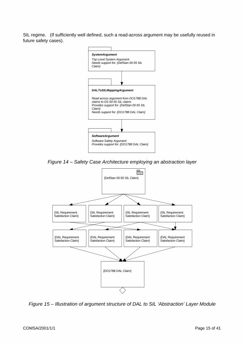
COMSA/2001/1/1 Page 15 of 41
SIL regime. (If sufficiently well defined, such a read-across argument may be usefully reused in future safety cases).
Top Level System Argument Needs support for: {DefStan 00-55 SILClaim}
SystemArgument
Software Safety Argument Provides support for: {DO178B DAL Claim}
SoftwareArgument
Read across argument from DO178B DALclaims to DS 00-55 SIL claims Provides support for: {DefStan 00-55 SILClaim} Needs support for: {DO178B DAL Claim}
DALToSILMappingArgument
Figure 14 – Safety Case Architecture employing an abstraction layer
{DefStan 00-55 SIL Claim}
{SIL RequirementSatisfaction Claim}
{SIL RequirementSatisfaction Claim}
{SIL RequirementSatisfaction Claim}
{SIL RequirementSatisfaction Claim}
{DAL RequirementSatisfaction Claim}
{DAL RequirementSatisfaction Claim}
{DAL RequirementSatisfaction Claim}
{DAL RequirementSatisfaction Claim}
{DO178B DAL Claim}
Figure 15 – Illustration of argument structure of DAL to SIL ‘Abstraction’ Layer Module

Page 16 of 41 COMSA/2001/1/1
Figure 15 illustrates the possible internal structure of the read-across argument contained within the middle tier of the safety case architecture shown in Figure 14. The published goal of the read-across argument is the claim expressed in the form required by the target application context (i.e. in this case in terms of a Defence Standard 00-55 SIL Claim). This claim is then decomposed into the specific claims regarding the key process and product requirements required (according to 00-55) in order to satisfy the SIL requirement (e.g. testing claims, claims regarding coding standards, language choice etc.). At the bottom of the argument shown in Figure 15 is an (undeveloped) goal regarding compliance to a Development Assurance Level that is known to be supportable from the available evidence (i.e. from the bottom tier of the architecture shown in Figure 14). Working bottom-up, the read-across argument then infers that in order to support this DAL claim the individual requirements dictated by DO178B for this DAL must also have been satisfied. The argument therefore draws out (above the DAL claim) these individual implicated sub-claims. The challenge in creating the read-across argument now lies in relating the specific claims required in order to support the SIL claim to the specific claims required in order to support the DAL claim. This approach attempts to read-across from one claim to another by deconstructing each claim in to its constituent parts and then relating these parts. It should be noted that the interrelation of SIL and DAL subclaims depicted in Figure 15 (where claims of one type are shown to be directly supportable by claims of the other) is a simplification. In reality, more complex chains of argument should be expected between the claims of each type.
9 Managing Changes to a Modular Safety Case
Maintainability is one of the principle objectives in attempting to partition a safety case into separate modules. When change occurs that impacts traditional safety cases (defined as total entities for a specific configuration of system elements) reassessment of the ‘whole’ case is often necessary in order to have confidence in a continuing argument of safety. In such situations it will often be the case that for certain forms of change large parts of the safety required no reassessment. However, without having formally partitioned these parts of the case behind well-defined interfaces and guarantees defined by contracts it is difficult to justify non re-examination of their arguments.
When changes occur that impact a modular safety case it is desirable that these changes can be isolated (as far as is possible) to a specific set of modules whilst leaving others undisturbed. The definition of interfaces and the agreement of contracts mean that the impact path of change can be halted at these boundaries (providing interfaces are sustained and contracts continue to be upheld).
Figure 16 illustrates the principle steps involved in maintaining a conventional GSN-based safety case argument, taken from [12]. The principal strength of modular safety cases will be observed when carrying out Step 3 (Identifying Impact) through being able to state with confidence that the effects of change do not propagate outside of a safety case module boundary providing that the interface is preserved. The interfaces defined for modular safety cases will also help in carrying out Step 4 (Deciding upon a recovery action to fix a ‘broken’ argument) in showing clearly the ‘non-negiotiable’ safety properties that must be upheld through any change suggested to the safety argument in order to re-establish the argument.

COMSA/2001/1/1 Page 17 of 41
Damage Phase
Use GSNto Identify
Impact
Step 3
Decide uponRecovery
Action
Step 4
RecoverIdentifiedDamagedArgument
Step 5
ExpressChallenge inGSN Terms
Step 2
RecogniseChallenge toSafety Case
Step 1
Safety CaseChallenge
GSNChallenge
GSNImpact
RecoveryAction
Recovery Phase
Figure 16 – A Process for Safety Case Change Management
In extremis for an IMA system it is desirable that when entire modules of the system are replaced, applications removed or added, or when the hardware of part of the system is substituted for that of a different vendor correspondingly entire modules of the safety case can be removed and replaced for those that continue to sustain the same safety properties. However, in order to achieve this flexibility, the following considerations need to be made for both the definition of context and the nature of cross-references made between modules:
• Avoid unnecessary restriction of context – It was highlighted in section 6 that the significant ‘side-condition’ of composing two or more modules together is that their collective context must be consistent. Often, the more specialised or restricted context is defined the harder it becomes to satisfy this condition (through incompatibility between defined contexts being more likely). For example, one module of the safety case may assume for the purposes of its argument that the temperature operating range is 10-20°C (i.e. the safety argument holds assuming the operating temperature is no less than 10°C and not greater than 20°C) whilst another modules may assume that the operating temperature is 20-30°C. Both ranges would form part of the defined context for each module and would create an inconsistency upon composition of the modules.
There will be specific occasions when it is necessary to restrict the assumed context of an module in order for the module argument argument to hold. However, narrowing of context should be avoided as far as is possible. An analogy can be made with the operating range of a conventional mains power adaptor. If the adaptor is qualified over the entire operating range 110-250 volts then it may be used in wider number of situations (e.g. for both 110-120V main supply and 230-240V mains supply). If the adaptor is qualified to a narrower operating range then obviously its scope of applicability is more restricted.
• Goals to be supported within modules should state limits rather than objectives – Borrowing terminology from the ALARP (As Low as Reasonably Practicable) framework [13], ‘limits’ refer to the boundary between tolerable and intolerable risks, whilst ‘objectives’ refer to the boundary between tolerable and negligible risks. In order to permit the widest range of possible solutions of combinations with other modules, unsupported goals within a module (i.e. goals that will have to be supported through composition of this module with another) should define acceptability criteria rather than ‘desirability criteria’. (More informally, this means stating “what you will accept” vs. “what you want”). It is easier to for another module to exceed (i.e. improve upon) a limit than it is to fail to meet an objective that was too harshly defined. Wherever possible boundary goals should ideally
Page 18 of 41 COMSA/2001/1/1
communicate both of limit and objective aspects of any requirement (by means of defining clearly the acceptance context of any undeveloped goal).
• Goals to be supported within modules and ‘Away’ Goals should refer to ‘ends’ rather than ‘means’ – This issue has already been briefly discussed in Section 8. In a similar vein to the previous observation, if goals on the boundary of modules or cross-references to goals between modules refer to claims regarding outcomes (e.g. a claim of memory partitioning) rather than means of achieving these outcomes (e.g. the specific mechanisms that ensure memory partitioning) then this leaves flexibility as to how solutions (supporting arguments) are provided – i.e. many possible alternative argument modules may be composed with this reference rather than just one specific form of argument.
A true assessment of the modifiability of any proposed safety case architecture can only be achieved through consideration of realistic change scenarios and examination of their impact on the module structure of the architecture. This form of evaluation is discussed further in the following section.
10 Evaluation of Safety Case Architecture
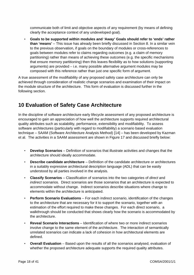
In the discipline of software architecture early lifecycle assessment of any proposed architecture is encouraged to gain an appreciation of how well the architecture supports required architectural quality attributes such as scalability, performance, extensibility and modifiability. To assess software architectures (particularly with regard to modifiability) a scenario based evaluation technique – SAAM (Software Architecture Analysis Method) [14] – has been developed by Kazman et al. The activities in a SAAM assessment are shown in Figure 17 and discussed briefly below:
• Develop Scenarios – Definition of scenarios that illustrate activities and changes that the architecture should ideally accommodate.
• Describe candidate architecture – Definition of the candidate architecture or architectures in a suitably expressive architectural description language (ADL) that can be easily understood by all parties involved in the analysis.
• Classify Scenarios – Classification of scenarios into the two categories of direct and indirect scenarios. Direct scenarios are those scenarios that an architecture is expected to accommodate without change. Indirect scenarios describe situations where change to elements within the architecture is anticipated.
• Perform Scenario Evaluations – For each indirect scenario, identification of the changes to the architecture that are necessary for it to support the scenario, together with an estimation of the effort required to make these changes. For each direct scenario, a walkthrough should be conducted that shows clearly how the scenario is accommodated by the architecture.
• Reveal Scenario Interactions – Identification of where two or more indirect scenarios involve change to the same element of the architecture. The interaction of semantically unrelated scenarios can indicate a lack of cohesion in how architectural elements are defined.
• Overall Evaluation – Based upon the results of all the scenarios analysed, evaluation of whether the proposed architecture adequate supports the required quality attributes.

COMSA/2001/1/1 Page 19 of 41
Stage 1Scenariodevelopment
Stage 2Architecturedescription
Stage 3Classificationof scenarios
Stage 4Individualevaluation ofscenarios
Stage 5Assessmentof scenariointeraction
Stage 6Overallevaluation
Figure 17 – Activities in a SAAM Analysis
With little modification, this method of architecture evaluation can be read-across to the domain of safety case architecture. One of the overriding aims in defining a modular safety case architecture is improve maintainability and (as a subtype of maintainability) extensibility. However, it is difficult to determine a priori whether a proposed safety case architecture (such as that presented in section 11) will be maintainable. Adopting a similar approach to SAAM but for safety case architectures would suggest that a number of change ‘scenarios’ should be identified. These scenarios should attempt to anticipate all credible changes that could impact the safety case over its lifetime (e.g. a change of hardware manufacturer, addition of functionality). For each of these change scenarios (NB – by definition these scenarios would be classified as indirect in the SAAM methodology), a walkthrough should be conducted to assess the likely impact of the change upon the individual modules of the proposed safety case architecture.
In the SAAM method, the effects of indirect scenarios are classified according to the following three classes of change:
• Local Change – change isolated within a single module of the architecture.
• Non-Local Change – change forced to a number of modules within the architecture.
• Architectural Change – widespread change forced to a large proportion of modules within the architecture.
These ideas can also be usefully applied to the safety case architecture domain. Ideally, for a modular safety partitioned and carefully cross referenced in accordance with the principles stated in this report the effects of all credible scenarios would fall within the first of the categories listed above. To illustrate how the categories of change read-across to the concept of a modular safety case architecture consider a simple safety case architecture as shown in Figure 18 containing the following four modules:
SysArg Safety case module containing the top level safety arguments for the overall system identifying top level claims for each application run as part of the system and a top level claim regarding the safety of the interactions between applications.
AppAArg Safety case module containing the arguments of safety for Application A.
AppBArg Safety case module containing the arguments of safety for Application B.
InteractionArg Safety case module containing the arguments of safety for the interactions between Applications A and B.

Page 20 of 41 COMSA/2001/1/1
SysArg
AppBArg
AppAArg InteractionArg
Figure 18 – A Simple Safety Case Architecture
The ‘SysArg’ module is supported by the ‘AppAArg’, ‘AppBArg’ and ‘InteractionArg’ modules. The ‘AppAArg’ module relies upon guarantees of safe interaction with Application B as defined by the claims contained within the ‘InteractionArg’ module (hence ‘AppAArg’ is shown making a contextual reference to ‘InteractionArg’). Similarly, the safety argument for Application B (‘AppBArg’) relies upon guarantees of safe interaction with Application A as defined in the ‘InteractionArg’ module. The following are three possible change scenarios that could have an impact on the outlined safety case architecture
Scenario #1 Application A is rewritten (perhaps including some additional functionality) but still preserves the safety obligations as defined in the contract between AppAArg, SysArg and InteractionArg.
Scenario #2 Application A is rewritten and interacts with Application B differently from before.
Scenario #3 Change is made to the system memory management model that enables new means of possible (unintentional) interaction between applications.
The effect of scenario #1 would be that the safety argument for Application A (‘AppAArg’) would need revision to reflect the new implementation. However, provided that the safety obligations of the module to the other modules (as defined by the contracts between the module safety case interfaces) continue to be upheld no further change to other modules would be necessary. Figure 19 depicts the effects of this scenario (a cross over a module indicates that the module is ‘challenged’ by the change and revision is necessary). The effects of this scenario could be regarded as a local change.
The effect of scenario #2 would be that not only must the safety argument for Application A (‘AppAArg’) be revised but in addition the safety argument for the interaction between modules (contained in ‘InteractionArg’) would need to be rexamined in light of the altered interaction between applications A and B. If, however, the revised ‘InteractionArg’ could continue to support the same assurances to the Application B argument of the safety of interactions with Application A then the Application B safety arguments (contained in ‘AppBArg’) would be unaffected. Figure 20 depicts the effects of this scenario. The effects of this scenario could be regarded as a non-local change (owing to the fact that the change impact has spread across a number of modules).

COMSA/2001/1/1 Page 21 of 41
SysArg
AppBArg
AppAArg InteractionArg
Figure 19 – Illustration of Local Change
SysArg
AppBArg
AppAArg InteractionArg
Figure 20 – Illustration of Non-Local Change
SysArg
AppBArg
AppAArg InteractionArg
Figure 21 – Illustration of Architectural Change

Page 22 of 41 COMSA/2001/1/1
The effect of scenario #3 is that it changes the nature of possible interactions between all applications. As such, the safety argument for the interaction between modules (contained in ‘InteractionArg’) would obviously need to be revised. It is likely that the nature of the assurances given by interaction argument to the safety arguments for applications A and B (as defined by the contracts between ‘InteractionArg’ and ‘AppAArg’, and between ‘InteractionArg’ and ‘AppBArg’) could be altered. Consequently both of these modules could be impacted. The change to the memory management model may even such that it alters the nature of the top level claim that needs to be made in the ‘SysArg’ module regarding the safety of application interactions (i.e. the ‘SysArg’ module may also be affected. Figure 21 depicts the effects of this scenario. The effects of this scenario could be regarded as architectural (owing to the fact that the change can potentially impact many modules). This is perhaps to be expected as this scenario describes modifying a fundamental services provided as part of the system infrastructure.
11 Modularised Generic IMA Safety Argument
The principles of modularising and evaluating safety case architecture have been applied in reworking a “Generic Avionics Safety Argument” developed by Pygott and presented in Appendix A. The resultant safety case architecture is shown in Figure 22. (Note – for clarity not all of the dependencies between modules have been shown on this diagram). The role of each of the modules of the safety case architecture shown in Figure 22 is as follows:
ApplnAArg Specific argument for the safety of Application A (one required for each application within the configuration)
CompilationArg Argument of the correctness of the compilation process. Ideally established once-for-all.
HardwareArg Argument for the correct execution of software on target hardware. Ideally abstract argument established once-for-all leading to support from SpecificHardwareArg modules for particular hardware choices.
ResourcingArg Overall argument concerning the sufficiency of access to, and integrity of, resources (including time, memory, and communications)
ApplnInteractionArg Argument addressing the interactions between applications, split into two legs: one concerning intentional interactions, the second concerning non-intentional interactions (leading to the NonInterfArg Module)
InteractionIntArg Argument addressing the integrity of mechanism used for intentional interaction between applications. Supporting module for ApplnInteractionArg. Ideally defined once-for-all.
NonInterfArg Argument addressing non-intentional interactions (e.g. corruption of shared memory) between applications. Supporting module for ApplnteractionArg. Ideally defined once-for-all
PlatFaultMgtArg Argument concerning the platform fault management strategy (e.g. addressing the general mechanisms of detecting value and timing faults, locking out faulty resources). Ideally established once-for-all. (NB Platform fault management can be augmented by additional management at the application level).

COMSA/2001/1/1 Page 23 of 41
ModeChangeArg Argument concerning the ability of the platform to dynamically reconfigure applications (e.g. move application from one processing unit to another) either due to a mode change or as requested as part of the platform fault management strategy. This argument will address state preservation and recovery.
SpecificConfigArg Module arguing the safety of the specific configuration of applications running on the platform. Module supported by once-for-all argument concerning the safety of configuration rules and specific modules addressing application safety.
TopLevelArg The top level (once-for-all) argument of the safety of the platform (in any of its possible configurations) that defines the top level safety case architecture (use of other modules as defined above).
ConfigurationRulesArg Module arguing the safety of a defined set of rules governing the possible combinations and configurations of applications on the platform. Ideally defined once-for-all.
TransientArg Module arguing the safety of the platform during transient phases (e.g. start-up and shut-down). Ideally generic arguments should be defined once-for-all that can then be augmented with arguments specifically addressing transient behaviour of applications.
An important distinction is drawn between those arguments that ideally can be established as ‘once-for-all’ arguments that hold regardless of the specific applications placed on the architecture (and should therefore be unaffected by application change) and those that are configuration dependent. Examples of application configuration specific modules include the ‘ApplnAArg’, ‘ApplnBArg’ and ‘ApplnInteractionsArg’ modules. Examples of the argument models established ‘once for all’ include the ‘NonInterfArg’ and ‘InteractionIntArg’ modules. Table 2 summarises the modules falling under each category.
Argument Modules Established ‘Once-for-all’ Configuration Dependent Argument Modules
ApplnAArg CompilationArg HardwareArg ResourcingArg InteractionIntArg NonInterfArg PlatFaultMgtArg ModeChangeArg TopLevelArg ConfigurationRulesArg TransientArg
ApplnAArg ApplnInteractionArg SpecificConfigArg
Table 2 – Categorisation of Safety Case Architecture Modules

Page 24 of 41 COMSA/2001/1/1
Top Level System Argument for theplatform + configured applications
TopLevelArg
Specific safetyargumentsconcerning thefunctionality ofApplication A
ApplnAArg
Specific safetyargumentsconcerning thefunctionality ofApplication B
ApplnBArg
Argument for thesafety of interactionsbetween applications
ApplnInteractionArg
Arguments of theabsence ofnon-intentionalinterference betweenapplications
NonInterfArg
Arguments of theintegrity of thecompilation path
CompilationArg (As Example)
Argumentsconcerning theintegrity of intentionalmechanisms forapplication interaction
InteractionIntArg
Safety argument for thespecific configuration ofthe system
SpecificConfigArg
Arguments of thecorrect execution ofsoftware on targethardware
Hardware Arg
Safety argumentbased upon anallowable set ofconfigurations
ConfigRulesArgArguments concerning theintegrity of the generalpurpose platform
PlatformArg
Arguments of the safetyof the platform duringtransient phases
TransientArg
Argument concerningthe platform faultmanagement strategy
PlatFaultMgtArgArguments concerningthe sufficiency ofaccess to, and integrityof, resources
ResourcingArg
Figure 22 – Safety Case Architecture of Modularised IMA Safety Argument
In the same way as there is an infrastructure and backbone to the IMA system itself the safety case modules that are established once for all possible application configurations form the infrastructure of this particular safety case architecture. These modules (e.g. NonInterfArg) establish core safety claims such as non-interference between applications by appeal to properties of the underlying system infrastructures. These properties can then be relied upon by the application level arguments.
Appendix B provides an indication of the claims present within the modules of the architecture shown by presenting the mapping of the original claims of the argument presented in Appendix A to modules shown in Figure 22. Where Appendix A indicates a goal being to be mapped to two modules this implies that the goal lies on the boundary between two modules – i.e. the first module will set the goal as an objective remaining to supported and the second module provides the supporting argument. Figure 23 illustrates this situation by showing example threads of arguments contained within each module and those spanning the module boundaries shown in Figure 22. The dotted lines denote module boundaries. Module ‘connect’ points (where the objectives of one module are satisfied by another) are shown by the double ball-ended lines connecting goals. (Note, not all of the arguments within each module can be shown in Figure 23 due to space limitations).

COMSA/2001/1/1 Page 25 of 41
<Overall Safety Goal>
System 'acceptable' System Definition
System acceptable under(physical) fault-free /fault-stable conditions
<Stable (fault) conditions>
System remains acceptable inthe presences/at the occuranceof physical faults
<Physical failure conditions>
<Stable (fault) conditions>
System acceptable under(physical) fault-free /fault-stable conditions
<Application correctness>
Each application's individualbehaviour is acceptable
Argument overapplications in currentconfiguration
ArgOverConfig
Current configurationof applications
Configuration
Application A'sindividual behaviouris acceptable
AppACorrect
AppACorrectApplication A'sindividual behaviour isacceptable
ApplnInteractionArg
ApplnB does not interferewith Appln A'scorrect operation
<Physical failure conditions>
System remains acceptable inthe presences/at the occuranceof physical faults
Spe
cific
Con
figA
rg
Pla
tFau
ltMgt
Arg
App
lnA
Arg
App
lnIn
ter-
actio
nArg
Top
Leve
lArg
Figure 23 – Illustration of Safety Case Partitioning
11.1 Reasoning about partitioning and independence
One of the main impediments to reasoning separately about individual applications running on an IMA based architecture separately is the degree to which applications interact or interfere with one another. DO178B [11], in discussing partitioning between software elements developed to differing Development Assurance Levels identifies that there are a number of possible routes through which interference is possible:

Page 26 of 41 COMSA/2001/1/1
• Hardware Resources – processors, memory, Input Output devices, timers etc.
• Control Coupling – vulnerability to external access
• Data Coupling – shared data, including processor stacks and registers.
• Hardware Failure Modes
For example, partitioning must be provided to ensure that one process cannot overwrite the memory space of another process. Similarly, a process should not be unintentionally allowed to overrun its allotted schedule such that it deprives another process of processor time.
The European railways safety standard CENELEC ENV 50129 [15] makes an interesting distinction between those interactions between system components that are intentional (e.g. component X is meant to communicate with component Y) are those that are unintentional (e.g. the impact of electromagnetic interference generated by one component on another).
Figure 24, taken from ENV 50129, depicts the influences affecting the independence between system elements. Unintentional interacts are typically the result of an error (whether random or systematic). For example, the unintentional interaction of one process overwriting the memory space of another is a fault condition. A further observation made in ENV 50129 is that there are a class of interactions that are non-intentional but created through intentional connections. An example of this form of interaction is the influence of a failed processing node that is ‘babbling’ and interfering with another node through the intentional connection of a shared databus.
The safety case architecture promotes (in the “NonInterfArg” module) the ideal that ‘once-for-all’ arguments are established by appeal to the properties of the IMA infrastructure to address unintentional interactions. For example, a “non interference through shared memory space” argument could be established by appeal to the segregation offered by a Memory Management Unit (MMU). An argument of “non-interference through shared scheduler” could be established by appeal to the priority-based scheduling scheme offered by the scheduler. Although the particular forms of interference between applications will need to be drawn out (within the “ApplnInteractionArg” module) it is expected that these specific arguments can be addressed through the general infrastructure arguments provided by the “NonInterfArg” module.
It is not possible to provide “once-for-all” arguments for the intentional interactions between components – as these can only be determined for a given configuration of components. However, it is desirable to separate those arguments addressing the logical intent of the interaction from those addressing the integrity of the medium of interaction. For example, if application A passes a data value to application B across a data bus it would be desirable to partition those arguments that address the possibility of A sending to wrong value to B from the arguments that address the possible corruption of the data value on the data bus. Both issues must be clearly identified and reasoned about (within the “ApplnInteractionArg” module). However, the supporting arguments concerning the integrity of the medium of interaction can be established “once-for-all” within the “InteractionIntArg” module.

COMSA/2001/1/1 Page 27 of 41
ITEM X
A
ITEM Y
B A
C2 D
C3
C1
C3 D C3 D
OUTPUT
"AND" condition for the non-restrictive state of the output
Legend: = INTENTIONAL CONNECTION
= NON-INTENTIONAL CONNECTION (possibly cause by a fault)
= INDEPENDENCE (if specified measures are met to avoid non-intentional influences and connections)
= FRONT CONTACT (normally-open contact)
= TWO FRONT CONTACTS (used symbolically as an AND for two independent non-restrictive activities)
A PHYSICAL INTERNAL INFLUENCE
B FUNCTIONAL INTERNAL INFLUENCE
C1 EXTERNAL ENVIRONMENTAL INFLUENCE (EMI, ---)(non-intentional)
C2 EXTERNAL INFLUENCE BY POWER SUPPLY(non-intentional using intentional connection)
C3EXTERNAL INFLUENCE ACROSS INPUT / OUTPUT
(non-intentional using intentional connection)(PROCESS WORKING VOLTAGES, EMI - INDUCED VOLTAGES)
D FUNCTIONAL EXTERNAL INFLUENCE(non-intentional using external connection)
Figure 24 – Influences affecting the independence of items (from ENV 50129)
Page 28 of 41 COMSA/2001/1/1
11.2 Minimising the Impact of Change
The intention of the partitioning of the safety case, such as in the approach described in the example above, is to maximise the number of arguments (modules) that are stable in the presence of change. As explained in section 10 in order to evaluate the success of the argument in this respect it is necessary to identify a number of credible change scenarios for the IMA-based system. Credible scenarios could include:
• Hardware Vendor Change
• Addition of a single application
• Removal of a single application
• Modification of existing application
• Addition of extra processing nodes
• Remove of processing nodes
• Change of Databus
Some of these scenarios may be accommodated easily by the proposed safety case architecture. For example, if the applications in a configuration change, although individual application arguments (e.g. “ApplnAArg” module) and application interaction arguments (i.e. those within the “ApplnInteractionArg” module) must be updated, argument of interaction integrity and non-interference (the “InteractionIntArg” and “NonInterfArg” modules) may well be able to stay unaltered. Other scenarios, such as change of hardware vendor may have a wider impact across the modules of the safety case (e.g. impacting compilation arguments as well as the more obvious hardware arguments).
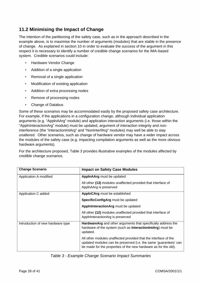
For the architecture proposed, Table 3 provides illustrative examples of the modules affected by credible change scenarios.
Change Scenario Impact on Safety Case Modules
Application A modified ApplnAArg must be updated
All other (13) modules unaffected provided that interface of ApplnAArg is preserved
Application C added ApplnCArg must be established
SpecificConfigArg must be updated
ApplnInteractionArg must be updated
All other (12) modules unaffected provided that interface of ApplnInteractionArg is preserved
Introduction of new hardware type HardwareArg and other arguments that specifically address the hardware of the system (such as InteractionIntArg) must be updated.
All other modules unaffected provided that the interface of the updated modules can be preserved (i.e. the same ‘guarantees’ can be made for the properties of the new hardware as for the old).
Table 3 - Example Change Scenario Impact Summaries

COMSA/2001/1/1 Page 29 of 41
It is through the ability to leave many of the modules of the safety case undisturbed in the presence of change (as illustrated in Table 3) that the benefits of IMA can be carried through to the certification process.
12 Implications for Certification Processes
A modular approach to safety case construction has implications on the acceptance process. Whereas, traditionally certification has involved accepting, at a single point in time, a single monolithic safety case for an entire system for the benefits of a modular safety case approach to be realised requires a certification process that acknowledges the structure of a partitioned safety case that can be extended and modified without instantly requiring re-evaluation of the entire case. The guidance document ARINC 651 [16] recognises this fact for suggests that for IMA-based systems the certification tasks are comprised of the following three distinct efforts:
• Confirmation of the general environment provided by the cabinet
• Confirmation of the operational behaviour of each function (application) intended to reside within a cabinet
• Confirmation of the resultant composite of the functions
ARINC 651 also recognises that conventional safety standards (such as DO178B [11]) may need to be updated to reflect these new distinct tasks. These observations can be clearly related to the example IMA safety case architecture presented within this report. Confirmation of the “general environment” involves qualification of both the hardware and software infrastructure (e.g. operating system) and relates to those modules shown within the proposed architecture that should ideally be established once for all possible application configurations (e.g. the ‘HardwareArg’ module). Confirmation of the operational behaviour of each function relates to the specific application argument modules (e.g. the ‘ApplnAArg’ module) shown within the proposed architecture. Confirmation of the composite operation of functions relates to those arguments, specific to a configuration of applications, that address the interaction of applications (e.g. the ‘ApplnInteractionArg’ and ‘SpecificConfigArg’ modules).
ARINC 651 talks explicitly of the need for “building block qualification” whereby it is possible to “separately quality certain building blocks of an IMA architecture in order to reduce the certification effort required for any particular IMA-hosted function”. Example building blocks listed include specific arguments relating to the (ARINC 629) global data bus, the ARINC 659 backplane bus, the robust partitioning environment and the cabinet hardware / software environment. Again, it is easy to see a correspondance with the IMA safety case architecture proposed within this report (e.g. the ‘NonInterfArg’ module addressing robust partitioning and the ‘InteractionIntArg’ module addressing the integrity of bus communication). However, no detail regarding how these building block arguments are to be represented and managed is presented within ARINC 651.
In order to design and validate the various building blocks involved in IMA, ARINC 651 identifies the need for “rules which govern how the building blocks work together”. It additionally describes that, “a feature of these rules of application is that they can be used to limit the work associated with certifying and re-certifying an IMA function to proof of compliance with the rules, and qualification of the function itself. Regulatory agency discussion is encouraged to establish how certification credit may be granted for adherence to these rules”. This concept of defining rules between building blocks relates strongly to the principles of establishing well-defined module interfaces and contracts between safety case modules put forward within this report. As the quote
Page 30 of 41 COMSA/2001/1/1
above clearly highlights, a necessary part of a new certification process based upon modular safety cases is to clearly give credit (i.e. limit the required re-certification) where contracts between safety case modules are upheld in the light of change to, or reconfiguration of, modules within the overall safety case.
13 Summary
In order to reap the potential benefits of modular construction of safety critical and safety related systems (e.g. ease of later addition or replacement of functionality, or through-life flexibility of hardware vendors) a modular approach to safety case construction and acceptance is also required. This report has explained some of the key concepts and principles of a modular safety case approach, including safety case module interface definition, cross-referencing between safety case modules and the steps involved in composition of one or more safety case modules. Specifically, the report has described how the Goal Structuring Notation (GSN) may be extended to include and support these concepts. Use of these extensions has been illustrated by means of an example modular safety case architecture for IMA-based systems.
Through defining the concept of modular safety case construction a new discipline of safety case architecture can be seen to emerge. This report has attempted to illustrate how concepts well established in the field of software architecture – such as scenario-based evaluation and architectural patterns - can now be seen to have obvious analogues in the safety case architecture domain. However, in this respect it is certain that the report only begins to explore the possible areas of study.
14 References
[1] C. Jones, "Specification and design (parallel) programs.," presented at IFIP Information Processing 83, 1983.
[2] T. P. Kelly, "A Six-Step Method for the Development of Goal Structures," York Software Engineering, Flixborough, U.K. 1997.
[3] C. Hofmeister, R. Nord, and D. Soni, Applied Software Architecture: Addison-Wesley, 1999.
[4] M. Buechi and W. Weck, "The Greybox Approach: When Black Specifications Hide Too Much," Turku Center for Computer Science ISBN 952-12-0508-3, August 1999.
[5] J. Lions, "ARIANE 5 Flight 501 Failure: Report by the Enquiry Board," European Space Agency, Paris 19 July 1996.
[6] S. Wilson and J. A. McDermid, "Integrated Analysis of Complex Safety Critical Systems," The Computer Journal, vol. 38, pp. 765-776, 1995.
[7] MoD, "00-56 Safety Management Requirements for Defence Systems," Ministry of Defence, Defence Standard December 1996.
[8] MoD, "00-55 Requirements of Safety Related Software in Defence Equipment," Ministry of Defence, Defence Standard August 1997.
[9] B. Meyer, "Applying Design by Contract," IEEE Computer, vol. 25, pp. 40-52, 1992.
[10] R. Helm, I. M. Holland, and D. Gangopadhyay, "Contracts: Specifying Behavioural Compositions in Object-Oriented Systems," presented at OOPSLA / ECOOP '90, 1990.

COMSA/2001/1/1 Page 31 of 41
[11] RTCA, "Software Considerations in Airborne Systems and Equipment Certification," RTCA, Washington D.C. DO-178B, December 1 1992.
[12] T. P. Kelly and J. A. McDermid, "A Systematic Approach to Safety Case Maintenance," Reliability Engineering and System Safety, vol. 71, pp. 271, 2001.
[13] HSE, "Reducing Risk, Protecting People," Health and Safety Executive, Discussion Document 1999.
[14] R. Kazman, G. Abowd, L. Bass, and P. Clements, "Scenario-based analysis of software architecture," IEEE Software, vol. 13, pp. 47-55, 1996.
[15] CENELEC, "Safety-related electronic systems for signalling," European Committee for Electrotechnical Standardisation, Brussels ENV 50129, June 1997.
[16] ARINC, "Design Guidance for Integrated Modular Avionics," Aeronautical Radio, Inc., Annapolis, Maryland Report 651, November 9 1991.
[17] Littlewood, Popov, Strigini and Shryane, “Modelling the effects of combining diverse software fault removal techniques”, Esprit long term research project 20072, DeVa (Design for Validation), Dec 1998
[18] C H Pygott, “Certification Analysis Techniques for an IMA Architecture”, DERA report DERA/CIS/CIS3/CR990865, Dec 1999
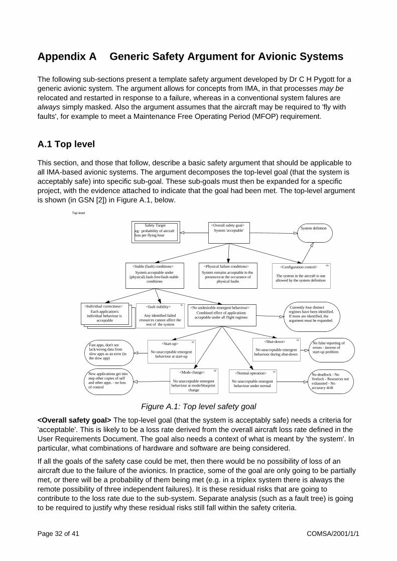
Page 32 of 41 COMSA/2001/1/1
Appendix A Generic Safety Argument for Avionic Systems
The following sub-sections present a template safety argument developed by Dr C H Pygott for a generic avionic system. The argument allows for concepts from IMA, in that processes may be relocated and restarted in response to a failure, whereas in a conventional system falures are always simply masked. Also the argument assumes that the aircraft may be required to 'fly with faults', for example to meet a Maintenance Free Operating Period (MFOP) requirement.
A.1 Top level
This section, and those that follow, describe a basic safety argument that should be applicable to all IMA-based avionic systems. The argument decomposes the top-level goal (that the system is acceptably safe) into specific sub-goal. These sub-goals must then be expanded for a specific project, with the evidence attached to indicate that the goal had been met. The top-level argument is shown (in GSN [2]) in Figure A.1, below.
Figure A.1: Top level safety goal
<Overall safety goal> The top-level goal (that the system is acceptably safe) needs a criteria for 'acceptable'. This is likely to be a loss rate derived from the overall aircraft loss rate defined in the User Requirements Document. The goal also needs a context of what is meant by 'the system'. In particular, what combinations of hardware and software are being considered.
If all the goals of the safety case could be met, then there would be no possibility of loss of an aircraft due to the failure of the avionics. In practice, some of the goal are only going to be partially met, or there will be a probability of them being met (e.g. in a triplex system there is always the remote possibility of three independent failures). It is these residual risks that are going to contribute to the loss rate due to the sub-system. Separate analysis (such as a fault tree) is going to be required to justify why these residual risks still fall within the safety criteria.
Top level
<Overall safety goal>System 'acceptable'
<Stable (fault) conditions>
System acceptable under(physical) fault-free/fault-stable
conditions
<Physical failure conditions>
System remains acceptable in thepresences/at the occurance of
physical faults
<Individual correctness>Each application's
individual behaviour isacceptable
<No undesirable emergent behaviour>Combined effect of applications
acceptable under all flight regimes
<Start-up>
No unacceptable emergentbehaviour at start-up
<Mode change>
No unacceptable emergentbehaviour at mode/blueprint
change
<Normal operation>
No unacceptable emergentbehaviour under normal
<Shut-down>
No unacceptable emergentbehaviour during shut-down
Safety Targeteg: probability of aircraftloss per flying hour
Currently four distinctregimes have been identified.If more are identified, theargument must be expanded.
New applications get intostep other copies of selfand other apps. - no lossof control
Fast apps, don't seelack/wrong data fromslow apps as an error (inthe slow app)
No false reporting oferrors - inverse ofstart-up problem
No deadlock - Nolivelock - Resources notexhausted - Noaccuracy drift
<fault stability>
Any identified failedresources cannot affect the
rest of the system
<Configuration control>
The system in the aircraft is oneallowed by the system definition
System defintion

COMSA/2001/1/1 Page 33 of 41
<Stable (fault) conditions> <Physical failure conditions> The top-level goal is sub-divided into two main sub-goals: that the system is acceptable under stable fault condition and when faults occur. These are considering physical faults only (not design or software errors - these will be considered later). Normally the system should either have no faults or a set of known faults that are being avoided (e.g. a processor has failed and processes have been allocated to use the other processing sites in the system, or the failed processor's results are being masked out in a voting system). This is the 'fault stable' situation, where the prime concern is that the applications work correctly2 (individually and/or collectively). The system must also remain acceptable when a fault occurs, and whilst the system recovers to (a different) fault-stable state. This is considered in section A.4.
<Configuration control> However, there is a third element to the top goal, there must be evidence that the system in the aircraft corresponds to the one3 being justified by the safety case. This brings in issues of configuration management, 'run-time' version checking etc.
The 'fault-stable' goal is addressed by three sub-goals: that the applications work correctly individually and together, and that any known faults are unable to affect the safe operation of the system. Individual application behaviour will be considered in section A.2.
<Fault stability> There needs to be evidence that faults that are being avoided really cannot affect the behaviour of the system. So if for example a system is configured to avoid a processor with a known failure, there should be evidence that this processor cannot affect the rest of the system, by for example the processor being held permanently inactive by having its reset continually asserted or by having all its off-card interfaces (busses, communications links etc) disabled. A corollary is that the existence of these mechanisms to disable a processor must be demonstrably incapable of being inadvertently activated.
<No undesirable emergent behaviour> There also needs to be evidence that the system is not going to exhibit any unacceptable 'emergent' behaviour caused by interactions between applications. This probably needs to be demonstrated for a number of separate flight regimes. It is suggested:
• <Start up>: what evidence is there that hazards cannot be generated, say by one application starting more rapidly than another with which it normally communicates?
• <Shut down>: essentially the reverse of the start-up. Could for example an application that feeds data into the engine manager close down 'early', leaving the engine manager to run up uncontrollably?
• <Normal operation>: under normal operation is the system free from issues such as deadlock (two or more processes each waiting for the other to complete some activity before it can advance), livelock (two or more processes involved in an endless cycle of unproductive activity, e.g. each acknowledging the acknowledgements from the other), exhaustion of resources, accuracy drift;
• <Mode change>: it is expected that future avionic systems will need to be reconfigured for different phases of flight, i.e. different sets of applications will need to be supported.
2 "correctly" and "acceptably" are going to be used interchangeably to mean 'so as to respect the safety
criteria' 3 or in general, the justification may be for a set of configurations, and it must be shown that the equipment
in the aircraft corresponds to a member of that set

Page 34 of 41 COMSA/2001/1/1
Evidence will have to be provided that the safety criteria can still be met whilst these reconfigurations take place.
Issues such as start-up take on a new significance with systems such as IMA that are expected to have a degree of fault-detection and reconfiguration built-in. Such fault recovery strategies depend upon a processor being identified as failed, possibly by its peers. There is a possibility that for example, a process that starts-up quickly reports a slower process it normally communicates with as failed, simply because it has not yet started communicating. Particularly if this effect is probabilistic (i.e. does not occur every time), then this may lead to much of the system's spare capacity being consumed before any real errors have occurred. This is certainly going to have reliability and mission effectiveness implications, and may have safety implications as well.
A.2 Applications
Whilst the top-level argument took the system level view, this sub-goal is essentially looking at the correctness of an individual application (although this has to be seen in the context of applications with which it interacts).
Figure A.2: Applications 'individually correct' goal
<Individual correctness> 'Correct' again means 'satisfies safety requirements'. So for an application this means that: the safety requirements must be identified, the application must be specified so as to respect these safety requirements, and must be implemented and executed to satisfy the safety requirements.
<Identify safety requirements> is likely to involve the analysis of some model(s) of the system, where the applications are the components of the model. Two main classes of requirement are likely to emerge: <continuous control> requirements - where at all times the application is required to maintain some output behaviour (dependant upon the corresponding inputs), and <safety properties> - where at all times the application's outputs are required to have some
Applications
<Individual correctness>Each application's individual
behaviour is acceptable
<Specification>
Specification meets safetyrequirements, and
expectations of otherapplications
<Implementation and execution>
Specification correctlyimplemented and executed with
respect to safety properties
<Establish Safe Behaviour>
This application has required safetyproperties - based on assumedbehaviour of other applications,
<Meets expectations>
Assumptions made by otherapplications about this
application are met
<Other applications>
Other applicationsbehaviour (datavalues, temporal)
A
<Continuous control>
Identify where the applicationmust maintain correct I/P -> O/P behaviour
<Safety properties>
Identify the safety propertiesthe application must maintain.That is: 'at all times ...', or '...
can never happen'
<Identify safety requirements>Safety requirements for this
application identified

COMSA/2001/1/1 Page 35 of 41
properties (e.g. 'never negative') but the actual values of the outputs (other than insofar as they satisfy the safety properties) are not important.
<Specification> It should then be shown that the specification for the application reflects these safety properties.
<Establish safe behaviour> It is likely that, in order to show that the safety properties are respected, the application's specification is going to have to make assumptions about other applications: such as the accuracy of the data they supply as inputs to this application, or when such input data is available.
<Meets expectations> Conversely, other applications are also likely to have made assumptions about this one. So, it is also necessary to show that this application's specification reflects those assumptions. In effect, the assumptions made by other applications (in order to achieve their safety objectives) become derived safety requirements on this application.
<Implementation and execution> Once it has been established that the safety requirements of an application are known and respected by its specification, it needs to be shown that the specification has been correctly implemented and can be correctly executed. This is covered in the next section (A.3).
A.3 Implementation and execution
Given that the application's safety requirements are known, it must be shown that the implementation will respect them, and that they are also respected during execution.
Figure A.3: Applications 'correctly implemented and executed' goal
Implementation and execution
<Implementation and execution>Specification correctly implemented and
executed with respect to safetyproperties
<code level>
Examine source orobject code
<Correct object code>
Object code respectssafety requirements
<Correct source+compiler>Both source code and
compiler shown to be correct
<Correct source code>
Source code respectssafety requirements
<Correct compilation>
Source correctly compiledto executable
<Run-time>Resources available to
this application
<Resources available>
Sufficient systemresources available
<Resource allocation>Resources available
when required <Resources needed>
Resource requirementsof all applicationsknown
A
<Implementation>Correct implementation of
safety properties
<Correct hardware execution>
The target hardware will correctlyexecute the implemented code
<Non-interference>
This application will not becorrupted by activities/failure of
another
<Allocation of time>
Each application gets thetime it needs to execute
<Allocation of memory>
Each application get thememory it needs to execute
<Allocation of communications>
Each application can communicatewhen required
<Exception Free Operation>
Execution of the applicationcannot generate run-time
exceptions with any legal inputs

Page 36 of 41 COMSA/2001/1/1
The principal requirements are that the implementation of the safety properties is correct and that the implemented code will be executed correctly. In addition, it is necessary to show that the behaviour of this application will not be significantly affected by the behaviour (or misbehaviour) of others.
<Implementation> Showing the implementation is correct requires either analysis (manual or mechanical examination of the code to be executed) or dynamic testing (execution of the code with appropriate test cases). For all but the simplest of applications, dynamic testing cannot give the level of confidence needed for critical systems. It has been shown [17] that for complex software, to demonstrate that it has a failure rate better than 10-n failures/hour needs 10n hours of dynamic testing. For high integrity applications, where N is likely to be around 9, this means dynamic testing is an impractical means of showing compliance, as any realistic testing is only going to sample a minuscule fraction of the input space.
If the application is sufficiently simple that dynamic testing can be used to show compliance, then if the dynamic testing can be performed on the target hardware, then this demonstrates not only that the software is correct (with respect to its safety properties) but also that it will be executed correctly.
However, nearly all applications are too complex to use this approach, so implementation correctness and correct execution have to be inferred by other means. Essentially this means analysing the code and arguing that the target hardware will correctly execute it.
<Correct object code> Analysis may occur on the compiled object code, based on some model of the semantics of the object code instructions. In such a case, how the object code was generated is essentially irrelevant.
<Correct source + compiler> Alternatively, <Correct source code> analysis may be performed at the source code level (based on the semantics of the source language), combined with an argument that the compiler will correctly transform source code to object code. <Correct compilation> In the past, for non-optimising compilers, a demonstration that all (legal) pair-wise combinations of language features are correctly compiled has been accepted as sufficiently strong evidence that the compiler will work as required.
<Correct hardware execution> In the absence of a formally developed processor for high-integrity applications, evidence that the hardware will correctly execute the object code is based on 'track record' for the processor4.
<Exception free operation> It would be expected that, if the program is implemented correctly, it should be free of run-time exceptions (divide-by-zero, type-violations etc). However, as an additional check on the implementation and as a check that the specification does not allow exceptional behaviour, there should be evidence that the code is free of run-time exceptions.
<Non-interference> For an application to be correctly executed, it must also be free of interference from other applications. Such interference might come in two ways: direct corruption or 'resource hogging'.
The resources an application needs are essentially: memory, communications and time. Direct corruption really only affects memory. It ought to be possible to show that one application cannot
4 The processor is seen as the most critical element of the hardware, because it has the most complex
and least regular structure, so is most like software insofar as dynamic testing is a poor indicator of design correctness. In systems with other complex hardware components (such as memory management units), similar evidence is required of their suitability (see also 5.2.4).

COMSA/2001/1/1 Page 37 of 41
interfere with the memory of another: either because their memory spaces are physically disjoint, or because some hardware protection is provided to stop an application addressing outside some allowed memory space, or because analysis has shown that the application's memory spaces are logically disjoint. In the later case, the question must also be addressed, 'what happens if a hardware fault causes an application to address outside its expected range'. That is, whilst logically two applications may be using different memory spaces, a hardware fault could cause them to overlap. In a system with multiple copies of applications, this may not be a problem, provided the failure is detected and a fault management strategy triggered (see next section).
<Run-time> For all three resources it must be demonstrated that the resources are available and allocateable when required. That is, the system has sufficient resources to meet all applications (simultaneous) needs and the these resources can be allocated when required and are not 'hogged' by another application. This might lead to fixed memory, time or communication slot allocation, but more complex strategies could be used, provided that it can be shown that no permitted or fault-induced behaviour in one application can cause another application to violate its safety properties.
A.4 Fault management
The previous sections have considered applications running under 'normal' conditions. This section will consider the effect of hardware failures.
Figure A .4: Management of physical failures
Essentially, for each (critical) application, there are two alternatives: mask a failure or remove it.
Fault conditions
<Physical failure conditions>System remains acceptable in the
presences/at the occurance ofphysical faults
Each application: faultmasked or removed?
<Faults masked>Multiple copies + voting
<Fault removal>Failed task relocated
to spare resource
<Fault detected>Task failures are reliably
detected<Move process>
Process can be restared on anew processing site
<Resynchronisation>
Safety requirements are maintainedwhilst relocated task is made fully
operational (data brought up to dateand included in voting groups)
<Multiple failures>
Probability of multipleor common-causefailures defeating voting
<Voting margins>
For non-exact voting, accuracyof comparison doesn't introduce
unacceptable inaccuracy
<Fault detection coverage>
What is the probability of afault going undetected?
<Effect of false alarms>
Erroneous fault reporting iseither eliminated or cannot
<Relocation>Successful process
'move'
<Silence failed processor>
A failed processor can besilenced, but this mechanism
cannot destroy a workingprocess
<Safety maintained>
During the fault removalprocess, safety requirements
are maintained
<Multiple failures during removal>What is the effect of a furtherfailure during fault removal?
<No spare capacity >Effect of sparecapacity exhausted

Page 38 of 41 COMSA/2001/1/1
<Faults masked> Currently, avionic systems tend to involve triplex or quadruplex systems for critical outputs, where the three or four results are 'voted' upon to generate a consensus. In effect, a faulty result is simply ignored (or masked).
<Voting margins> It is rare that the mechanism uses exact voting, there is usually some 'fuzzy' margin of error. This represents the level of divergence that can remain in the system after voting. Evidence is required that this divergence cannot cause safety problems. With any such system there is always a residual risk that multiple independent failures or some common cause error will cause an erroneous output to be generated.
<Fault removal> By contrast, in IMA systems it is possible that the effect of a failure will be to cause the faulty process5 to be moved to a spare processor and restarted. The advantage of this scheme is that the system can tolerate more failures before a complete system failure occurs. This either: increases the probability of a system meeting its MFOP targets, or allows a triplex system to replace a quadruplex without reducing system reliability [18] - it probably cannot be used to do both simultaneously.
If fault removal is required, then four separate aspects need consideration and justification: fault detection, process relocation, resynchronisation and maintenance of safety requirements during the relocation process.
<Fault detected> Before a fault can be removed, it must be detected. Two important issues are: what proportion of failures are detected and what is the consequence of incorrectly diagnosing a process as failed, particularly if there is possibility of a common-mode error causing multiple copies of a process all to be (incorrectly) identified as faulty. If faults are detected by voting, then as in the fault masking case, there is the question of the effect of inexact voting.
<Relocation> Whilst conceptually it is possible to talk of 'moving a failed process to spare capacity', in practice the failed process must be closed down and a new copy started elsewhere. What is more, not only the process identified as failed must be 'moved', but all those that were running on the same processing site (and which were presumably exposed to the same hardware failure).
<Silence failed processor> The ability to close the failed processor down is important, as once a processor has been identified as failed, nothing about its behaviour can be guaranteed. In particular there is the possibility of it corrupting the memory space of other processes, or hogging some resource (memory, communications or time), and thus preventing another process from running correctly.
However, the ability of the system to 'shutdown' a processor6 may itself be open to abuse, and it must be shown that the system cannot erroneous shutdown processors without good cause, particularly if there is the possibility of the same processes being affected in multiple lanes due to a common-mode failure.
<Move process> The system also needs to be able to find a spare processing site (assuming one is available), load the required code, restart the process and re-establish communication links with other processes etc., without disturbing those processes that are essential for safety (it might be for example that during fault removal, an entire lane is regarded as failed and ignored. If so this has implications for the effect of a second failure. If the 'fault containment' unit is smaller, then there is
5 i.e. all the processes running on a processor that has failed 6 by, for example; disabling all its output drivers, removing power from it, permanently holding it reset or by
removing its clock.

COMSA/2001/1/1 Page 39 of 41
less likelihood of a subsequent failure leading to a safety violation, but the mechanisms to ensure segregation are likely to be more complex and hence harder to verify).
<Resynchronise> Whilst the 'process move' activity has moved the 'failed' process to a new working site, the new process still needs to 'get in step' with the other copies running in other lanes. The process may be storing two types of data: that which is refreshed on a regular basis and that which records external 'events'. For example, multiple copies of an N-stage digital filter will be synchronised after N steps7, no matter what their initial starting conditions are. If all the data stored by a program is like this, then it only needs to wait a finite time to get back into step. Conversely, if a program's state depends individual external event, such as pilot actions, then some active mechanism must be provided to acquire this historic data from somewhere. Two possibilities are:
a. maintain the data locally (in the same lane as the process that uses it) in such a way that the process can be relocated, but still get access to the data. This may require multiple copies in different memories on separate cards to the processor using the data.
b. acquire the data from the equivalent process in a different lane. It must then be shown that this cross-lane activity doesn’t lead to failures in the lane supplying the data (by, for example, the additional work load causing it to miss a deadline), and that this cannot be a source of common-mode failure between lanes (a wrong data value copied to another lane).
Whilst all the above is happening, it must be demonstrated that the system maintains the required safety properties.
7 given the same inputs.

Page 40 of 41 COMSA/2001/1/1
Appendix B: Goal to Module Mapping
This appendix contains the mapping of the goals contained with the “Generic Avionics Safety Argument” presented in Appendix A to the reworked modularised safety case architecture presented within section 11 of this report (shown in Figure 22)
Goal from Appendix A Attributed Module
<Overall safety goal> TopLevelArg
<Stable (fault) condition> TopLevelArg
PlatFaultMgtArg
<fault stability> PlatFaultMgtArg
ResourcingArg
<Physical failure condition>
+ supporting arguments
PlatFaultMgtArg
<Relocation> PlatFaultMgtArg
ModeChangeArg
<Configuration Control> TopLevelArg
ConfigurationRulesArg
<No undesirable emergent behaviour> TransientArg
ApplnInteractArg
<Start-up> TransientArg
<Shut-down> TransientArg
<Mode Change> TransientArg
ModeChangeArg
<Individual applications safe>
(<Individual Correctness>)
TopLevelArg
SpecificConfigArg
<Application A safe> SpecificConfigArg
ApplnAArg
<Safety Properties> ApplnAArg
<Implementation and Execution> ApplnAArg
<Correct source+compiler> ApplnAArg
CompilationArg
<Correct Hardware Execution> ApplnAArg
HardwareArg

COMSA/2001/1/1 Page 41 of 41
<Run-time> ApplnAArg
ResourcingArg
<Safe App Interaction> ApplnAArg
ApplnInteractionArg
<Critical Dependencies Safe> ApplnInteractionArg
<Non-interference> ApplnInterationArg
<Interaction Integrity> ApplnInteractionArg
InteractionIntArg
<Exception Free Operation> ApplnAArg
Note - Where the above table indicates a goal being to be mapped to two modules this implies that the goal lies on the boundary between two modules – i.e. the first module will set the goal as an objective remaining to supported and the second module provides the supporting argument.