Concept and Parameters for Ground Improvement illustrated ...
122
1 ISSMGE PERM – MASTER CLASS – November 16th, 2010 Concept and Parameters for Ground Improvement illustrated by case histories by СЕРГЕЙ ВАРАКСЙН Serge VARAKSIN Chairman T.C. Ground Improvement (TC 211)
Transcript of Concept and Parameters for Ground Improvement illustrated ...

1
ISSMGE
PERM – MASTER CLASS – November 16th, 2010
Concept and Parameters for Ground Improvement illustrated by case
histories
by
СЕРГЕЙ ВАРАКСЙНSerge VARAKSIN
Chairman T.C. Ground Improvement (TC 211)
PERM – MASTER CLASS – NOV 2010
PARAMETERS RELATED TO GROUND IMPROVEMENT FROM PARAMETERS RELATED TO GROUND IMPROVEMENT FROM IN SITU TESTSIN SITU TESTS

PERM – MASTER CLASS – NOV 2010
Menard Pressumeter (PMT)Static Cone Penetration (CPT)Dynamic Penetration (SPT)Vane Test (VT)Some correlations
Parameters related to ground improvement from in situ tests

PERM – MASTER CLASS – NOV 2010
Vane test(VT)
Static ConePenetrationTest (CPT)
DynamicPenetrationTest (SPT)
Pressuremeter(PMT)
Parameters related to ground improvement : Differents types of in situ tests
PERM – MASTER CLASS – NOV 2010
THE MENARD PRESSUREMETERTHE MENARD PRESSUREMETER
PERM – MASTER CLASS – NOV 2010
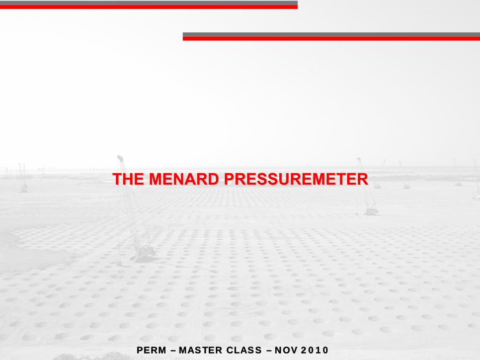
Typical load tests conducted on foundations : (i) PBT; and (ii) PMT (not CPT or SPT)
PBT – vertical load test
PMT – shear loading test
The Menard Pressuremeter : Typical loading tests
PERM – MASTER CLASS – NOV 2010
EP
PL
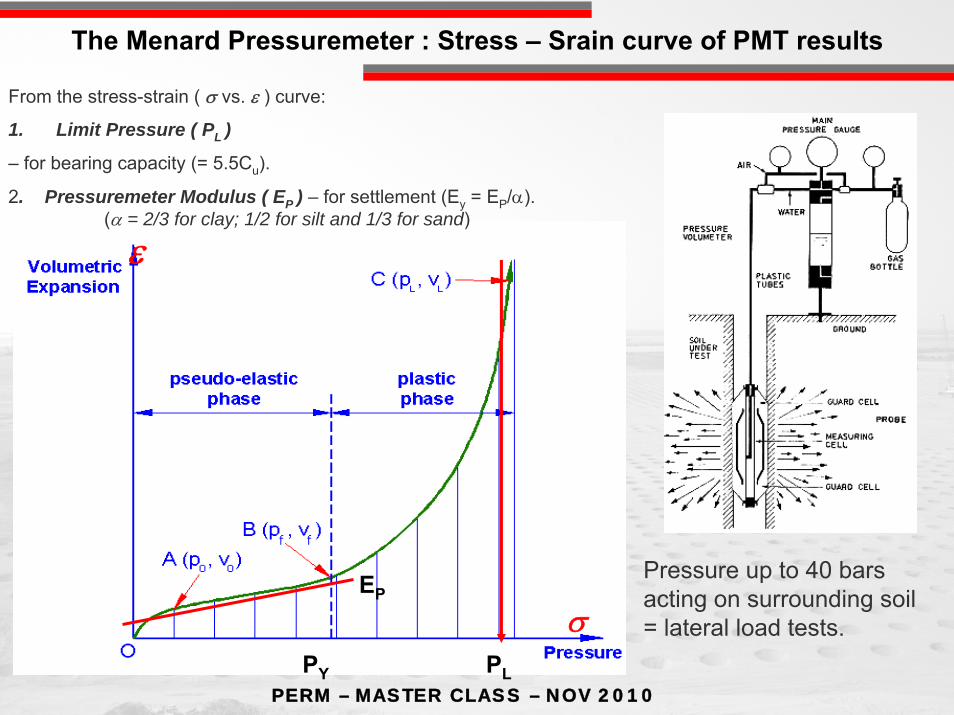
From the stress-strain ( σ vs. ε ) curve:
1. Limit Pressure ( PL )
– for bearing capacity (= 5.5Cu).
2. Pressuremeter Modulus ( EP ) – for settlement (Ey = EP/α). (α = 2/3 for clay; 1/2 for silt and 1/3 for sand)
Pressure up to 40 bars acting on surrounding soil = lateral load tests.σ
ε
PY
The Menard Pressuremeter : Stress – Srain curve of PMT results
PERM – MASTER CLASS – NOV 2010
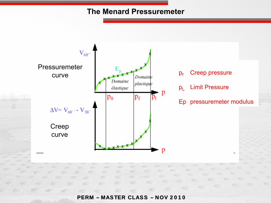
pf Creep pressure
pL Limit Pressure
Ep pressuremeter modulus
Creepcurve
Pressuremetercurve
The Menard Pressuremeter
PERM – MASTER CLASS – NOV 2010
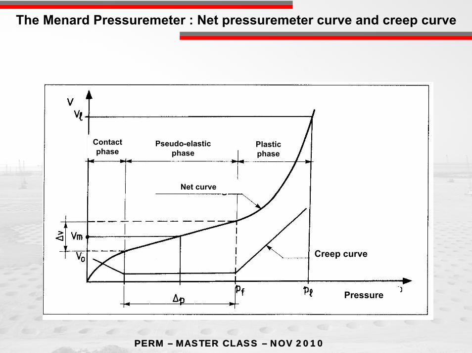
Creep curve
Pressure
Plasticphase
Pseudo-elasticphase
Contactphase
Net curve
The Menard Pressuremeter : Net pressuremeter curve and creep curve
PERM – MASTER CLASS – NOV 2010
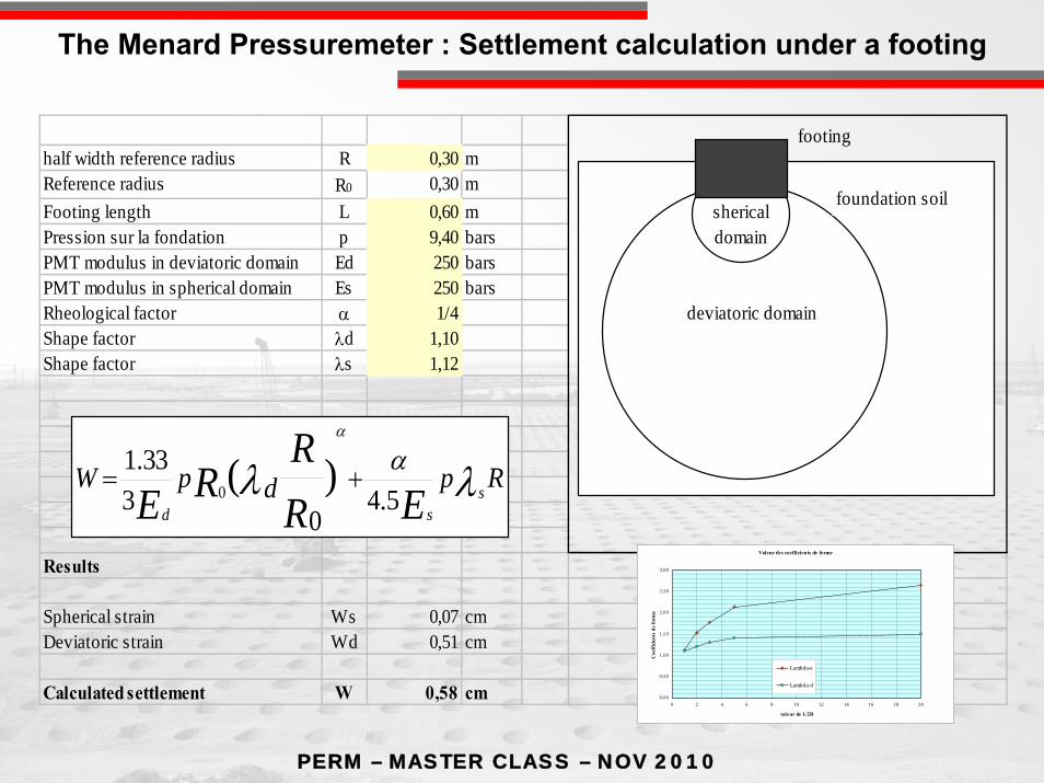
half width reference radius R 0,30 mReference radius R0 0,30 mFooting length L 0,60 mPression sur la fondation p 9,40 barsPMT modulus in deviatoric domain Ed 250 barsPMT modulus in spherical domain Es 250 barsRheological factor α 1/4Shape factor λd 1,10Shape factor λs 1,12
Results
Spherical strain Ws 0,07 cmDeviatoric strain Wd 0,51 cm
Calculated settlement W 0,58 cm
RpdpW ssd ER
RRE λλ α
α
5.40
333.1 )(0 +=
deviatoric domain
shericaldomain
footing
foundation soil
Valeur des coefficients de forme
0,00
0,50
1,00
1,50
2,00
2,50
3,00
0 2 4 6 8 10 12 14 16 18 20
valeur de L/2R
Coe
ffic
ient
s de
form
e
Lambda-s
Lambda-d
The Menard Pressuremeter : Settlement calculation under a footing
PERM – MASTER CLASS – NOV 2010
STATIC PENETRATION TEST (C.P.T.)STATIC PENETRATION TEST (C.P.T.)

PERM – MASTER CLASS – NOV 2010
Static Penetration Test (C.P.T.)

PERM – MASTER CLASS – NOV 2010
Static Penetration Test : Typical CPT Test
PERM – MASTER CLASS – NOV 2010
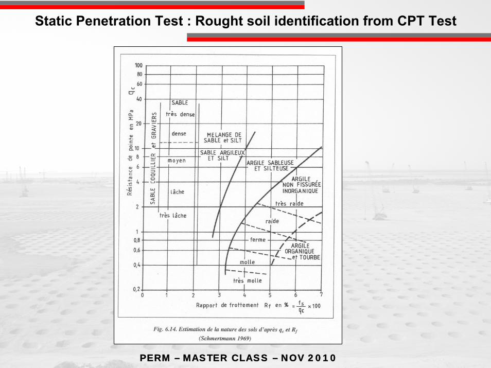
Static Penetration Test : Rought soil identification from CPT Test

PERM – MASTER CLASS – NOV 2010
DYNAMIC PENETRATION TEST (SPT, DPT)DYNAMIC PENETRATION TEST (SPT, DPT)

PERM – MASTER CLASS – NOV 2010
Von Moos DPT
Driving conical pond
anvil
Hamer(P=Weight)
Dynamic Penetration Test

PERM – MASTER CLASS – NOV 2010
Dynamic Penetration Test
PERM – MASTER CLASS – NOV 2010
VANE TESTVANE TEST((onlyonly in soft in soft homogeneoushomogeneous clayclay))
PERM – MASTER CLASS – NOV 2010
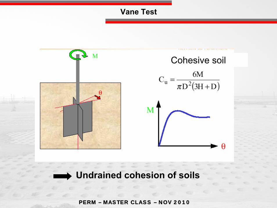
Undrained cohesion of soils
Cohesive soil
Vane Test
PERM – MASTER CLASS – NOV 2010
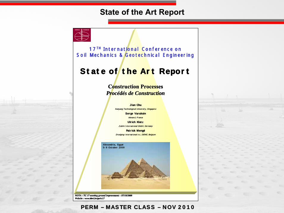
Construction ProcessesProcédés de Construction
17TH International Conference onSoil Mechanics & Geotechnical Engineering
Jian ChuNanyang Technological University, Singapore
Serge VaraksinMenard, France
Ulrich KlotzZublin International GmbH, Germany
Patrick MengéDredging International n.v., DEME, Belgium
State of the Art Report
NOTA : TC 17 meeting ground improvement – 07/10/2009Website : www.bbri.be/go/tc17
Alexandria, Egypt5-9 October 2009
State of the Art Report
PERM – MASTER CLASS – NOV 2010
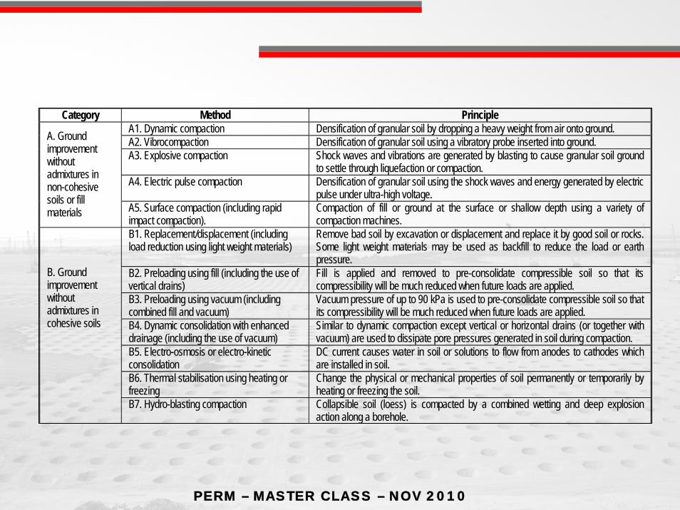
Category Method Principle A1. Dynamic compaction Densification of granular soil by dropping a heavy weight from air onto ground. A2. Vibrocompaction Densification of granular soil using a vibratory probe inserted into ground. A3. Explosive compaction Shock waves and vibrations are generated by blasting to cause granular soil ground
to settle through liquefaction or compaction. A4. Electric pulse compaction Densification of granular soil using the shock waves and energy generated by electric
pulse under ultra-high voltage.
A. Ground improvement without admixtures in non-cohesive soils or fill materials A5. Surface compaction (including rapid
impact compaction). Compaction of fill or ground at the surface or shallow depth using a variety of compaction machines.
B1. Replacement/displacement (including load reduction using light weight materials)
Remove bad soil by excavation or displacement and replace it by good soil or rocks. Some light weight materials may be used as backfill to reduce the load or earth pressure.
B2. Preloading using fill (including the use of vertical drains)
Fill is applied and removed to pre-consolidate compressible soil so that its compressibility will be much reduced when future loads are applied.
B3. Preloading using vacuum (including combined fill and vacuum)
Vacuum pressure of up to 90 kPa is used to pre-consolidate compressible soil so that its compressibility will be much reduced when future loads are applied.
B4. Dynamic consolidation with enhanced drainage (including the use of vacuum)
Similar to dynamic compaction except vertical or horizontal drains (or together with vacuum) are used to dissipate pore pressures generated in soil during compaction.
B5. Electro-osmosis or electro-kinetic consolidation
DC current causes water in soil or solutions to flow from anodes to cathodes which are installed in soil.
B6. Thermal stabilisation using heating or freezing
Change the physical or mechanical properties of soil permanently or temporarily by heating or freezing the soil.
B. Ground improvement without admixtures in cohesive soils
B7. Hydro-blasting compaction Collapsible soil (loess) is compacted by a combined wetting and deep explosion action along a borehole.

PERM – MASTER CLASS – NOV 2010
C1. Vibro replacement or stone columns Hole jetted into soft, fine-grained soil and back filled with densely compacted gravel or sand to form columns.
C2. Dynamic replacement Aggregates are driven into soil by high energy dynamic impact to form columns. The backfill can be either sand, gravel, stones or demolition debris.
C3. Sand compaction piles Sand is fed into ground through a casing pipe and compacted by either vibration, dynamic impact, or static excitation to form columns.
C4. Geotextile confined columns Sand is fed into a closed bottom geotextile lined cylindrical hole to form a column. C5. Rigid inclusions (or composite foundation, also see Table 5)
Use of piles, rigid or semi-rigid bodies or columns which are either premade or formed in-situ to strengthen soft ground.
C6. Geosynthetic reinforced column or pile supported embankment
Use of piles, rigid or semi-rigid columns/inclusions and geosynthetic girds to enhance the stability and reduce the settlement of embankments.
C7. Microbial methods Use of microbial materials to modify soil to increase its strength or reduce its permeability.
C. Ground improvement with admixtures or inclusions
C8 Other methods Unconventional methods, such as formation of sand piles using blasting and the use of bamboo, timber and other natural products.
PERM – MASTER CLASS – NOV 2010
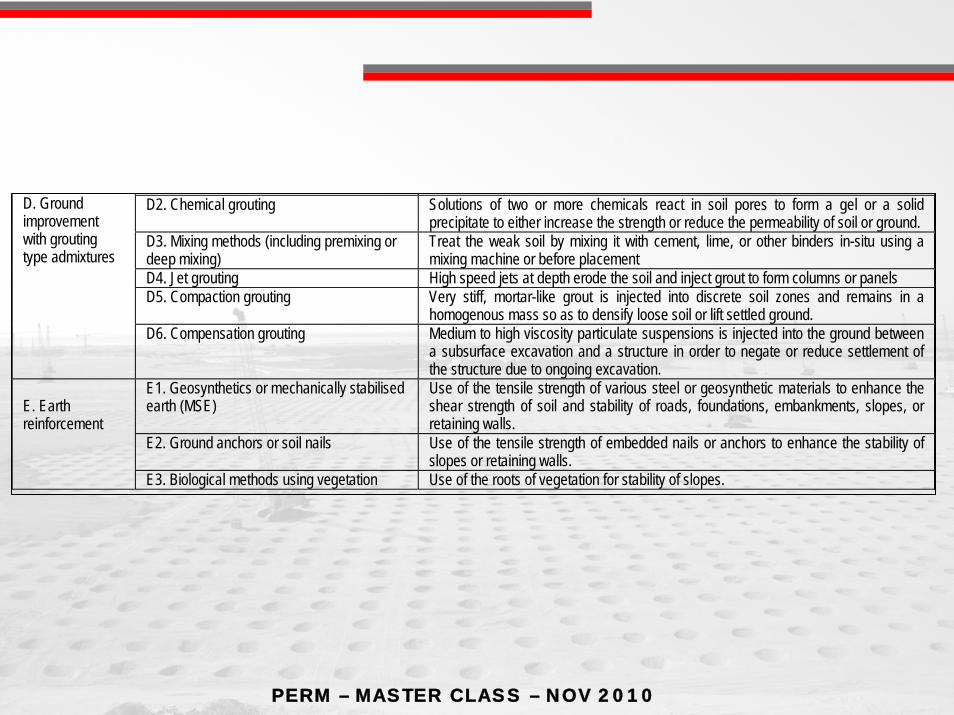
gD2. Chemical grouting Solutions of two or more chemicals react in soil pores to form a gel or a solid
precipitate to either increase the strength or reduce the permeability of soil or ground. D3. Mixing methods (including premixing or deep mixing)
Treat the weak soil by mixing it with cement, lime, or other binders in-situ using a mixing machine or before placement
D4. Jet grouting High speed jets at depth erode the soil and inject grout to form columns or panels D5. Compaction grouting Very stiff, mortar-like grout is injected into discrete soil zones and remains in a
homogenous mass so as to densify loose soil or lift settled ground.
D. Ground improvement with grouting type admixtures
D6. Compensation grouting Medium to high viscosity particulate suspensions is injected into the ground between a subsurface excavation and a structure in order to negate or reduce settlement of the structure due to ongoing excavation.
E1. Geosynthetics or mechanically stabilised earth (MSE)
Use of the tensile strength of various steel or geosynthetic materials to enhance the shear strength of soil and stability of roads, foundations, embankments, slopes, or retaining walls.
E2. Ground anchors or soil nails Use of the tensile strength of embedded nails or anchors to enhance the stability of slopes or retaining walls.
E. Earth reinforcement
E3. Biological methods using vegetation Use of the roots of vegetation for stability of slopes.

PERM – MASTER CLASS – NOV 2010
Why Soil improvement ?
•To increase bearing capacity and stability (avoid failure)
•To reduce post construction settlements
• To reduce liquefaction risk (sismic area)
• avoid deep foundation (price reduction also on structure work like slabon pile)
• avoid soil replacement
• save time
•Avoid to change site
•Save money !
Advantages / classical solutions
Laboratory Engineering Properties

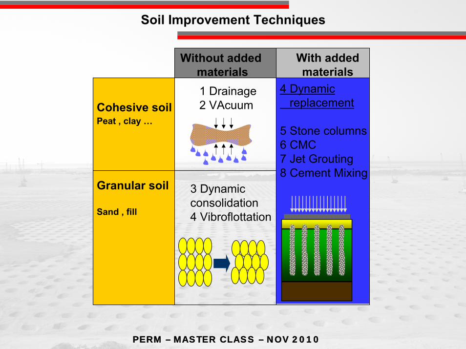
PERM – MASTER CLASS – NOV 2010
Cohesive soilPeat , clay …
Soil withfriction
Sand , fill
Without addedmaterials
With addedmaterials
1 Drainage 2 VAcuum
3 Dynamicconsolidation4 Vibroflottation
4 Dynamicreplacement
5 Stone columns6 CMC7 Jet Grouting8 Cement Mixing
Soil Improvement Techniques

PERM – MASTER CLASS – NOV 2010
-Soil caracteristics-cohesive or non cohesive- blocks ?
- Water content, water table position- Organic materials-Soil thickness-Structure to support
-Isolated or uniform load-Deformability
-Site environment
-Close to existing structure
-Height constraints
-Time available to build
Parameters For Concept

PERM – MASTER CLASS – NOV 2010
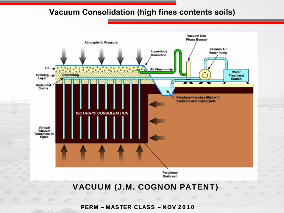
σ=σ’+u
high fines contents soils
Preloading with vertical drains
PERM – MASTER CLASS – NOV 2010
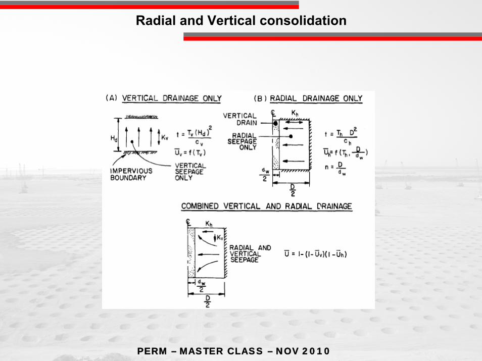
Radial and Vertical consolidation

PERM – MASTER CLASS – NOV 2010
High fines contents soils
5 cm , PVC vertical drain + geotextileFlat drain circular drain
Vertical drains: material
PERM – MASTER CLASS – NOV 2010
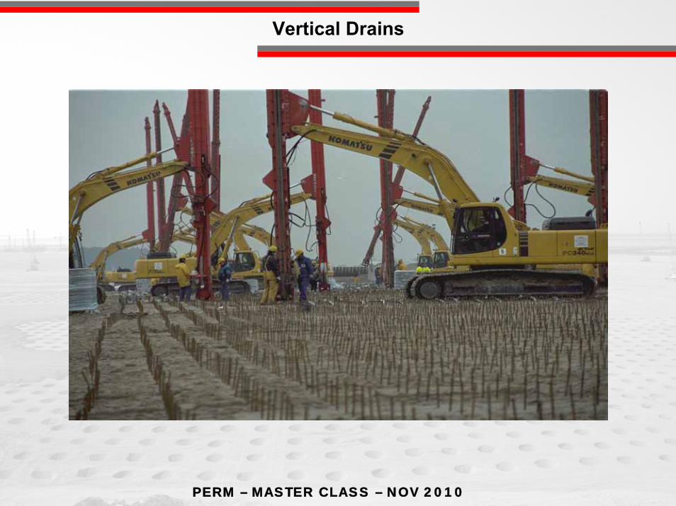
Vertical Drains
PERM – MASTER CLASS – NOV 2010
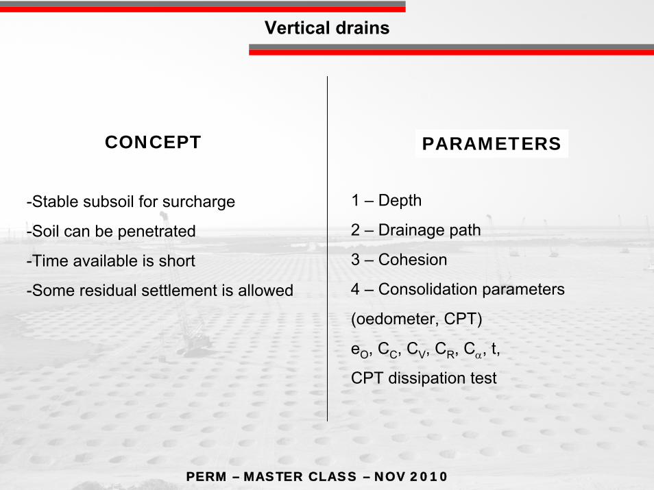
-Stable subsoil for surcharge
-Soil can be penetrated
-Time available is short
-Some residual settlement is allowed
1 – Depth
2 – Drainage path
3 – Cohesion
4 – Consolidation parameters
(oedometer, CPT)
eO, CC, CV, CR, Cα, t,
CPT dissipation test
CONCEPT PARAMETERS
Vertical drains
PERM – MASTER CLASS – NOV 2010
VACUUM (J.M. COGNON PATENT)
Vacuum Consolidation (high fines contents soils)
PERM – MASTER CLASS – NOV 2010
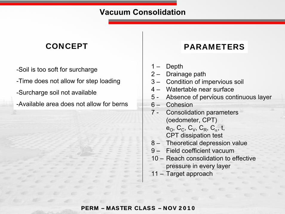
-Soil is too soft for surcharge
-Time does not allow for step loading
-Surcharge soil not available
-Available area does not allow for berns
1 – Depth2 – Drainage path3 – Condition of impervious soil4 – Watertable near surface5 - Absence of pervious continuous layer6 – Cohesion7 - Consolidation parameters
(oedometer, CPT)eO, CC, CV, CR, Cα, t, CPT dissipation test
8 – Theoretical depression value9 – Field coefficient vacuum10 – Reach consolidation to effective
pressure in every layer11 – Target approach
CONCEPT PARAMETERS
Vacuum Consolidation

PERM – MASTER CLASS – NOV 2010
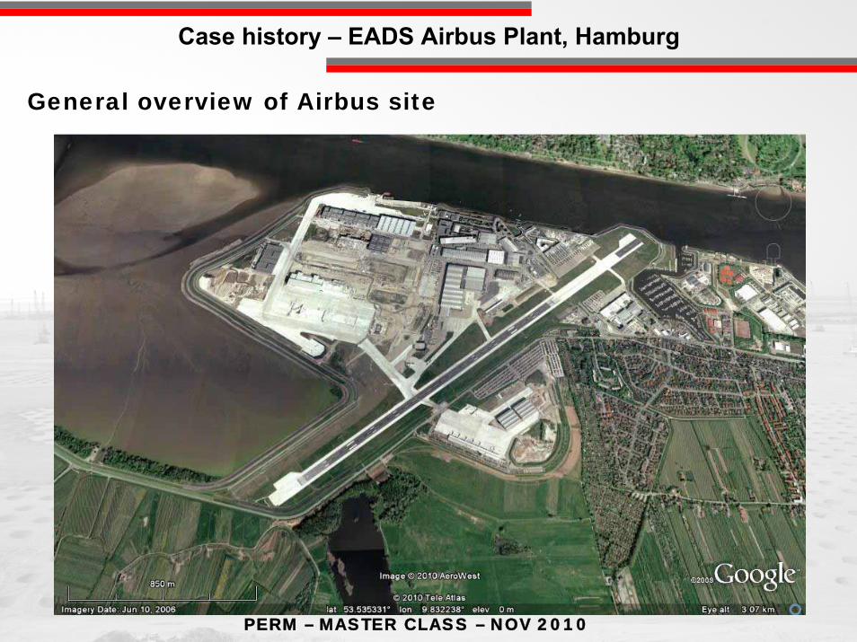
Case history – EADS Airbus Plant, Hamburg
PERM – MASTER CLASS – NOV 2010
General overview of Airbus site
Case history – EADS Airbus Plant, Hamburg

PERM – MASTER CLASS – NOV 2010
Dyke construction to +6.5 in 8.5 month and to + 9.00 in 16 month
Columns GCC Settlement 0,7 – 1.84 m
Settlement ≥ 2,0 – 5,5 m
Temporary sheet pile wall – in 5 month – dyke construction in 3 years
Dyke construction to +6.5 in 8.5 month and to + 9.00 in 16 month
Columns GCC Settlement 0,7 – 1.84 m
Settlement ≥ 2,0 – 5,5 m
Basic design and alternate concept of Moebius–Menard

PERM – MASTER CLASS – NOV 2010
Subsoil characteristics
PERM – MASTER CLASS – NOV 2010
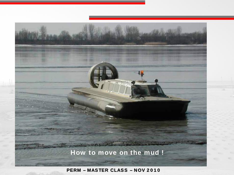
How to move on the mud !
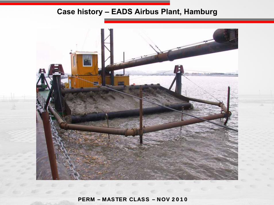
Case history – EADS Airbus Plant, Hamburg
PERM – MASTER CLASS – NOV 2010
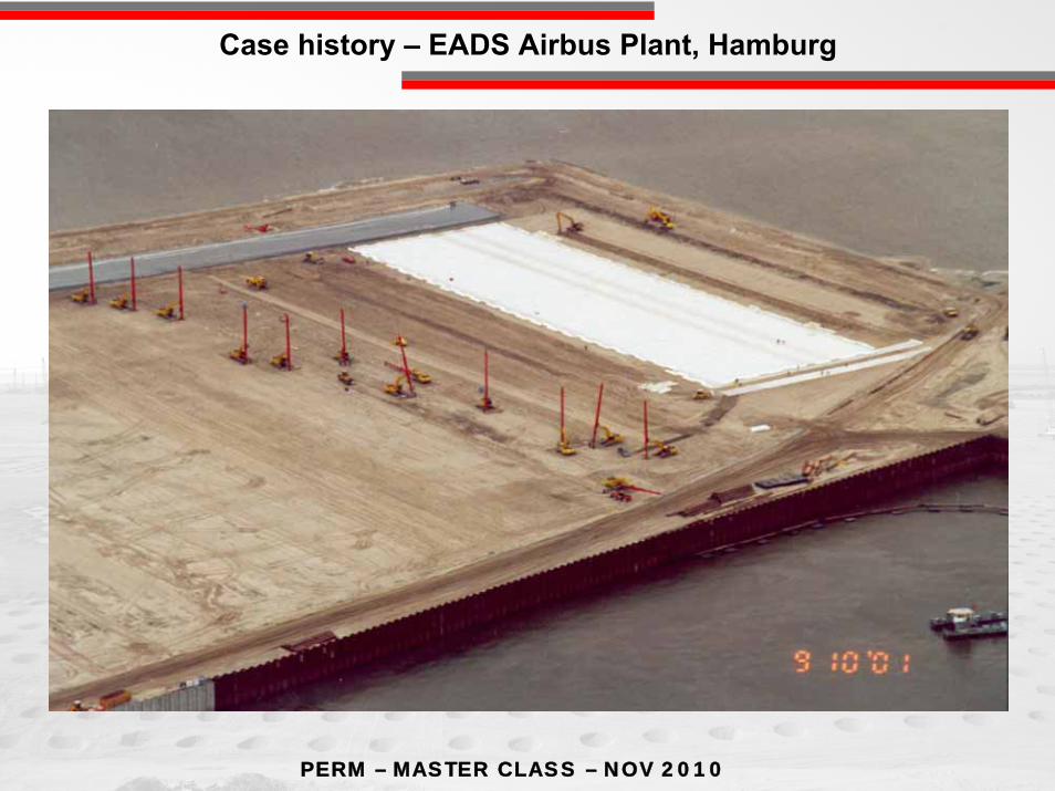
Case history – EADS Airbus Plant, Hamburg
PERM – MASTER CLASS – NOV 2010
Case history – EADS Airbus Plant, Hamburg

PERM – MASTER CLASS – NOV 2010
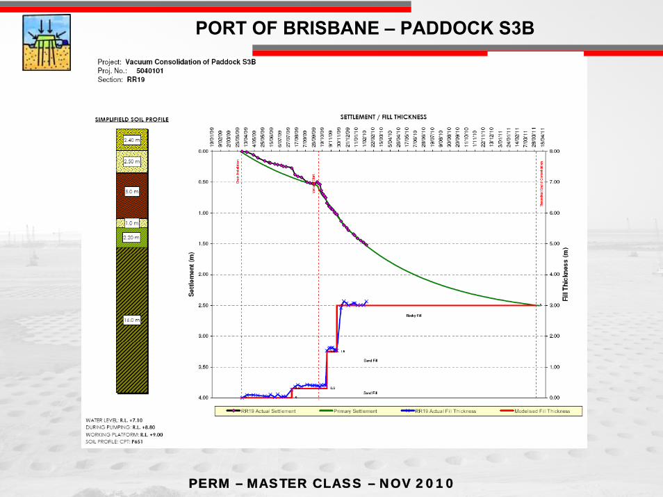
PORT OF BRISBANE – PADDOCK S3B
PROJECT OVERVIEW
Located at the mouth of the Brisbane river;New reclamation area: 234 ha enclosed in the Port
Expansion Seawall;Part of the new reclaimed area to be ready in 5years;Seawall construction completed in 2005;
Port of BrisbaneSydney 1000 km
PERM – MASTER CLASS – NOV 2010
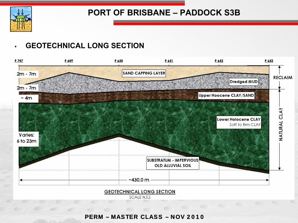
PORT OF BRISBANE – PADDOCK S3B
GEOTECHNICAL LONG SECTION

PERM – MASTER CLASS – NOV 2010
PORT OF BRISBANE – PADDOCK S3B
GEOLOGICAL PARAMETERS
Parameter Unit DredgedMaterial
Upper Holocene
Sand
UpperHolocene
Clay
Lower Holocene
ClayCc/(1+e0) [-] 0,235 0,01 0,18 0,235Cα/(1+e0) [-] 0,0059 0,001 0,008 0,0076
γ [kN/m3] 14 19 16 16Cv [m²/y] 1 10 10 0.9Ch [m²/y] 1 10 10 1.8Su [kPa] 4 - 20 28
Su / σ’v [-] 0,25 0,3 0,3 0,2
PERM – MASTER CLASS – NOV 2010
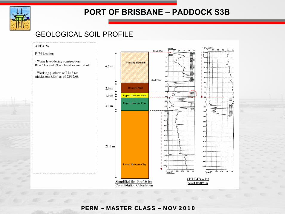
PORT OF BRISBANE – PADDOCK S3B
GEOLOGICAL SOIL PROFILE
PERM – MASTER CLASS – NOV 2010
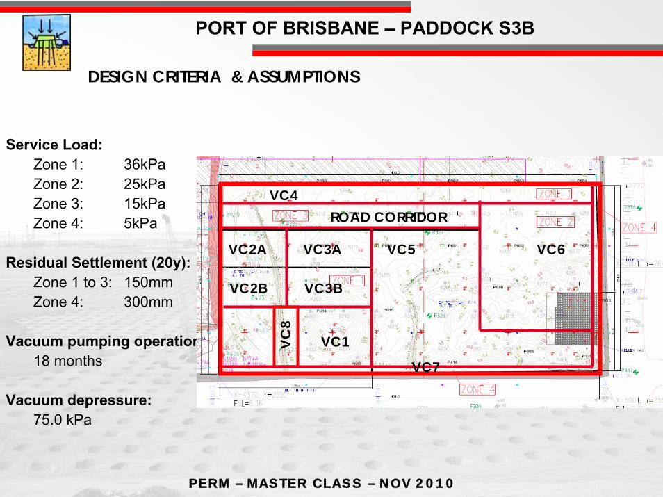
PORT OF BRISBANE – PADDOCK S3B
Service Load:Zone 1: 36kPaZone 2: 25kPaZone 3: 15kPaZone 4: 5kPa
Residual Settlement (20y):Zone 1 to 3: 150mmZone 4: 300mm
Vacuum pumping operation:18 months
Vacuum depressure:75.0 kPa
VC6
VC4
VC5VC3A
VC3B
VC2A
VC2B
VC1VC8
ROAD CORRIDOR
DESIGN CRITERIA & ASSUMPTIONS
VC7
PERM – MASTER CLASS – NOV 2010
PORT OF BRISBANE – PADDOCK S3B
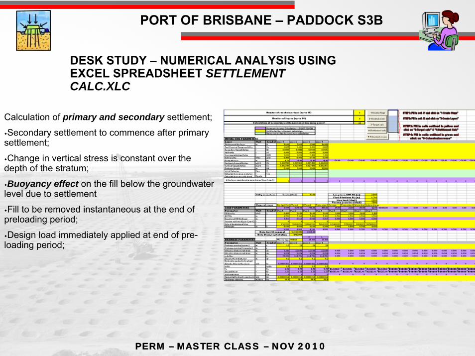
Calculation of primary and secondary settlement;
Secondary settlement to commence after primary settlement;
Change in vertical stress is constant over the depth of the stratum;
Buoyancy effect on the fill below the groundwater level due to settlement
Fill to be removed instantaneous at the end of preloading period;
Design load immediately applied at end of pre-loading period;
DESK STUDY – NUMERICAL ANALYSIS USING EXCEL SPREADSHEET SETTLEMENT CALC.XLC

PERM – MASTER CLASS – NOV 2010
PORT OF BRISBANE – PADDOCK S3B
Up to 15 surcharge steps;
Up to 30 soil layers;
Calculation of shear strength increaseduring consolidation of cohesive soils;
Different types of drains available:
MCD 34, MD88-3, FD767;
Effect of smear due to mandrel insertion
Graphical output Settlement / Fill thickness chart
DESK STUDY…

PERM – MASTER CLASS – NOV 2010
PORT OF BRISBANE – PADDOCK S3B
ANALYSIS METHOD
Secondary SettlementProgram uses a method based on Bjerrum’s concept to calculate instantaneous and delayed consolidation (Bjerrum, 1967).
σ’o Δlogσ’
Δe
σ’o+Δσ’f σ’o+Δσ’pxU%
eo
t=1d
t=To
t=To+20y
e1
e2
e3
σ’o Δlogσ’
Δe
σ’o+Δσ’f σ’o+Δσ’pxU%
eo
t=1d
t=To
t=To+20y
e1
e2
e3
Initial Initial StressStress
Service Service LoadLoad
Consolidation Consolidation LoadLoad
Void RatioVoid Ratio
Secondary Consolidation Secondary Consolidation (Long term Creep)(Long term Creep)
⎟⎟⎠
⎞⎜⎜⎝
⎛ Δ++
=Δ
o
finalo
o
primary
eCc
HH
'''
log1 σ
σσ
Primary Primary Consolidation Consolidation (Pore Pressure (Pore Pressure
Dissipation)Dissipation)
⎟⎟⎠
⎞⎜⎜⎝
⎛=Δ
pe T
yearsCe 20logα

PERM – MASTER CLASS – NOV 2010
PORT OF BRISBANE – PADDOCK S3B
CONSTRUCTION SEQUENCE
Impermeable Strata
VACUUMUNITS
VACUUMUNITS
SOIL BENTONITE CUT-OFF WALL
VERTICAL TRANSMISSION PIPES INSTALLATION
VERTICALMEMBRANE
HORIZONTAL TRANSMISSION PIPES INSTALLATION
MEMBRANE HDPE 1mmSEALING TRENCH BY BENTONITE PROTECTION FILL
1ST SURCHARGE PLACEMENT2ND SURCHARGE PLACEMENT
PERMEABLE LAYER

PERM – MASTER CLASS – NOV 2010
PORT OF BRISBANE – PADDOCK S3B
TYPICAL SBW CONSTRUCTION – LONG SECTION
Full roll of linerInner frame
Wheeled frame

PERM – MASTER CLASS – NOV 2010
PORT OF BRISBANE – PADDOCK S3B

PERM – MASTER CLASS – NOV 2010
PORT OF BRISBANE – PADDOCK S3B
Backfilling works
Trench excavation works under
bentonite slurry
Two membrane rolls - overlapping

PERM – MASTER CLASS – NOV 2010
PORT OF BRISBANE – PADDOCK S3B
PERM – MASTER CLASS – NOV 2010
PORT OF BRISBANE – PADDOCK S3B
PERM – MASTER CLASS – NOV 2010
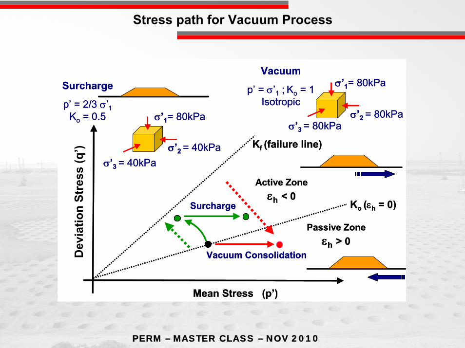
Dev
iato
ricSt
ress
(q
)
Mean Stress (p’)
Ko (εh = 0)
Kf (failure line)
Surcharge
σ’1= 80kPa
σ’2 = 40kPaσ’3 = 40kPa
Vacuum Consolidation
Active Zone εh < 0
Passive Zone εh > 0
Surcharge
p’ = 2/3 σ’1 Ko = 0.5
σ’1= 80kPa
σ’2 = 80kPaσ’3 = 80kPa
Vacuum
p’ = σ’1 ; Ko = 1 Isotropic
Dev
iato
ricSt
ress
(q
)
Mean Stress (p’)
Ko (εh = 0)
Kf (failure line)
Surcharge
σ’1= 80kPa
σ’2 = 40kPaσ’3 = 40kPa
Vacuum Consolidation
Active Zone εh < 0
Passive Zone εh > 0
Surcharge
p’ = 2/3 σ’1 Ko = 0.5
σ’1= 80kPa
σ’2 = 80kPaσ’3 = 80kPa
Vacuum
p’ = σ’1 ; Ko = 1 Isotropic
Dev
iatio
nSt
ress
(q’)
Stress path for Vacuum Process
PERM – MASTER CLASS – NOV 2010
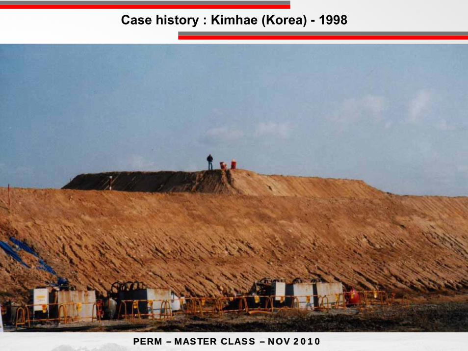
Case history : Kimhae (Korea) - 1998

PERM – MASTER CLASS – NOV 2010
Cohesive soilPeat , clay …
Soil withfriction
Sand , fill
Without addedmaterials
With addedmaterials
1 Drainage 2 VAcuum
3 Dynamicconsolidation4 Vibroflottation
4 Dynamicreplacement
5 Stone columns6 CMC7 Jet Grouting8 Cement Mixing
Soil Improvement Techniques

PERM – MASTER CLASS – NOV 2010
2
4
6
8
1012
FILL FILL+UNIFORM LOAD FILL+ LOAD
1
2
3
4
FILLDepth(m)
FILLDepth(m)
FILLDepth(m)
GWT GWT GWT
t(about 10 years)
S (%) 30% (SBC)50% (SBC)
60% (SBC)
80% (SBC)
90% (SBC)
SBCσ’z SBCσ’z SBCσ’z
DC : h(m) =
δ
ECδ
C(menard) = 0.9-1 C(hydraulic) = 0.55
SBC = 0.9-1 (SILICA SAND)
δ LOAD = 0.4-0.6 (SILICA SAND)
S.B.C. = Self Bearing CoefficientS.B.C. = S(t)
S( )∞
SB σ’z
σ’z30%
50%
80%
2
4
6
8
1012
FILL FILL+UNIFORM LOAD FILL+ LOAD
1
2
3
4
FILLDepth(m)
FILLDepth(m)
FILLDepth(m)
GWT GWT GWT
t(about 10 years)
S (%) 30% (SBC)50% (SBC)
60% (SBC)
80% (SBC)
90% (SBC)
SBCσ’z SBCσ’z SBCσ’z
DC : h(m) =
δ
ECδ
C(menard) = 0.9-1 C(hydraulic) = 0.55
SBC = 0.9-1 (SILICA SAND)
δ LOAD = 0.4-0.6 (SILICA SAND)
S.B.C. = Self Bearing CoefficientS.B.C. = S(t)
S( )¥
SB σ’z
σ’z30%
50%
80%
- Age if fill saturated or not-PL-Selfbearing level-∅-EP or EM-QC, FR,-N-R.D. (???)-Shear wave velocity-Seismic parameters-Grain size
CONCEPT PARAMETERS
Parameters for Concept
PERM – MASTER CLASS – NOV 2010
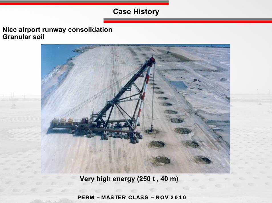
Nice airport runway consolidationGranular soil
Very high energy (250 t , 40 m)
Case History
PERM – MASTER CLASS – NOV 2010
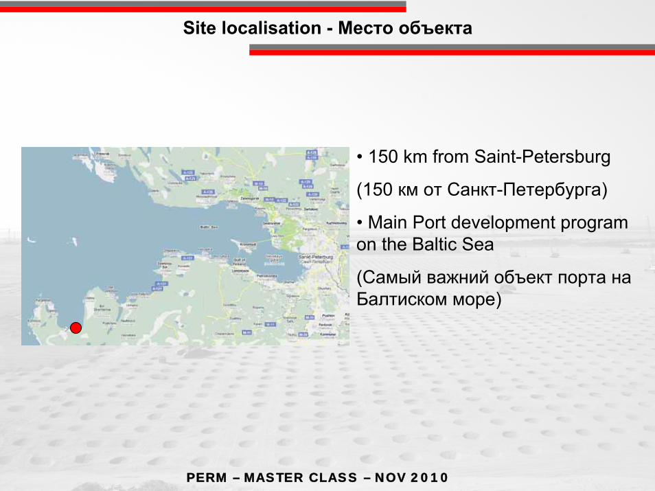
Site localisation - Место объекта
• 150 km from Saint-Petersburg
(150 км от Санкт-Петербурга)
• Main Port development program on the Baltic Sea
(Самый важний объект порта наБалтиском море)
PERM – MASTER CLASS – NOV 2010
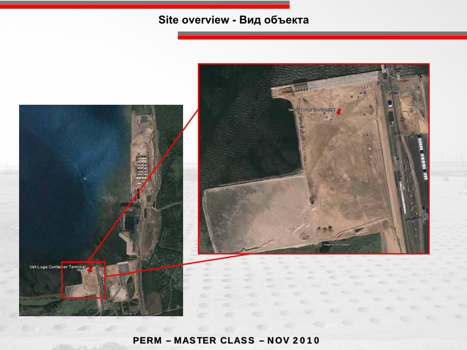
Site overview - Вид объекта
PERM – MASTER CLASS – NOV 2010
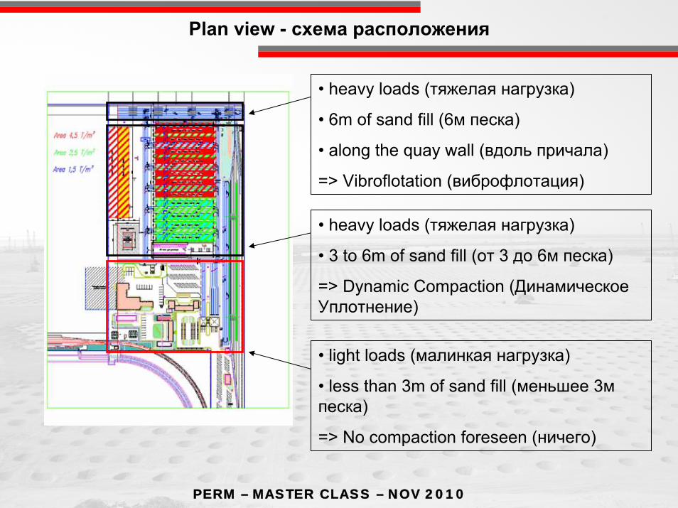
Plan view - схема расположения
• heavy loads (тяжелая нагрузка)
• 3 to 6m of sand fill (от 3 до 6м песка)
=> Dynamic Compaction (ДинамическоеУплотнение)
• light loads (малинкая нагрузка)
• less than 3m of sand fill (меньшее 3мпеска)
=> No compaction foreseen (ничего)
• heavy loads (тяжелая нагрузка)
• 6m of sand fill (6м песка)
• along the quay wall (вдоль причала)
=> Vibroflotation (виброфлотация)
PERM – MASTER CLASS – NOV 2010
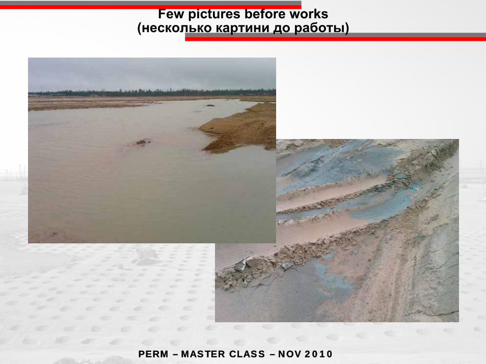
Few pictures before works(несколько картини до работы)
PERM – MASTER CLASS – NOV 2010
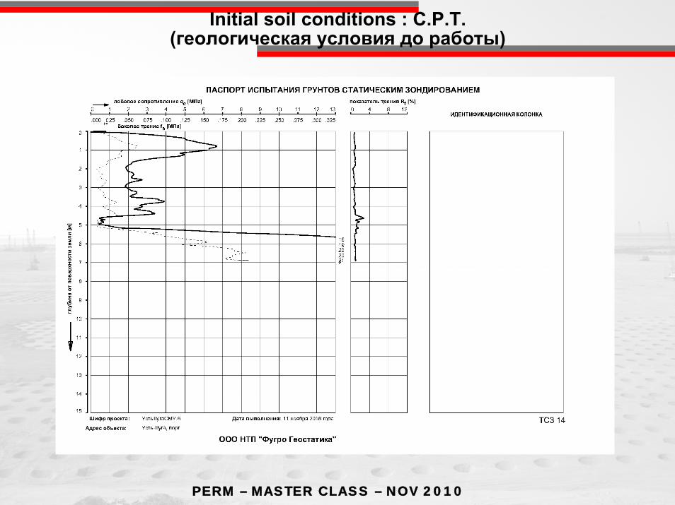
Initial soil conditions : C.P.T.(геологическая условия до работы)

PERM – MASTER CLASS – NOV 2010
Few pictures of the ongoing works : Vibroflotation(Картини от Виброфлотации)
PERM – MASTER CLASS – NOV 2010
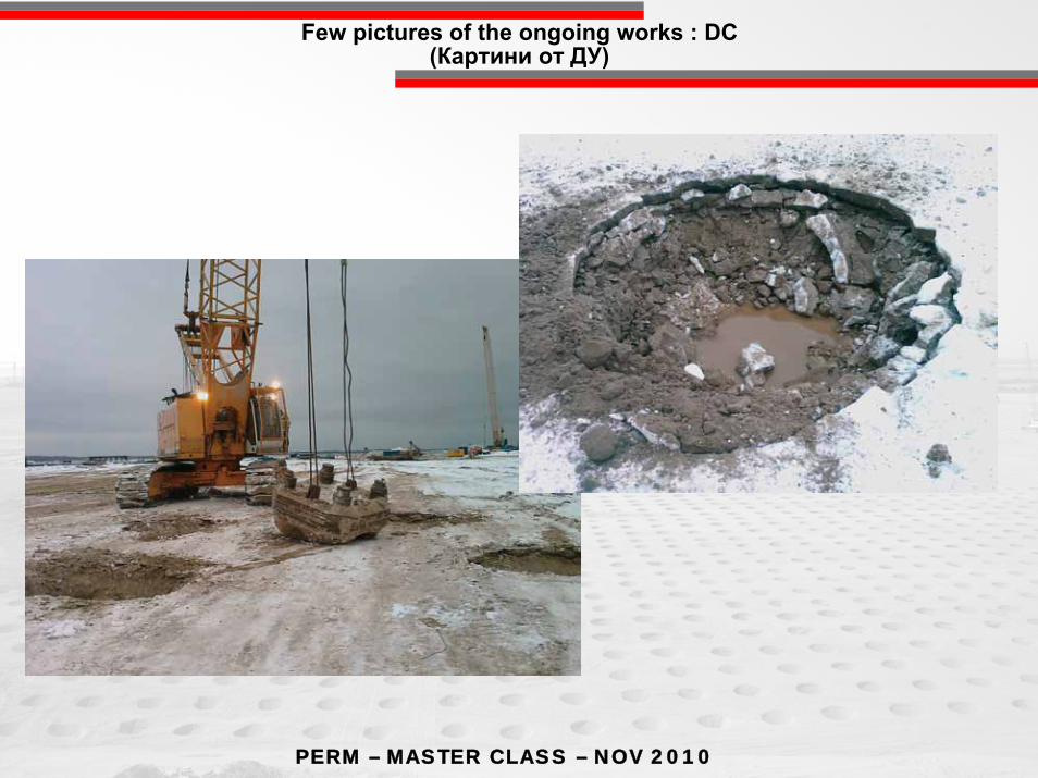
Few pictures of the ongoing works : DC(Картини от ДУ)

PERM – MASTER CLASS – NOV 2010
Results after compaction : Vibroflotation(Результат после Виброфлотации)
PERM – MASTER CLASS – NOV 2010
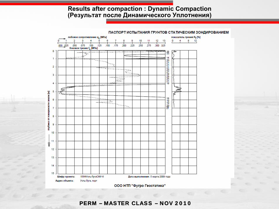
Results after compaction : Dynamic Compaction(Результат после Динамического Уплотнения)
PERM – MASTER CLASS – NOV 2010
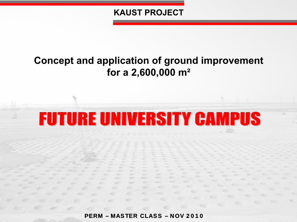
Concept and application of ground improvementfor a 2,600,000 m²
KAUST PROJECT
PERM – MASTER CLASS – NOV 2010
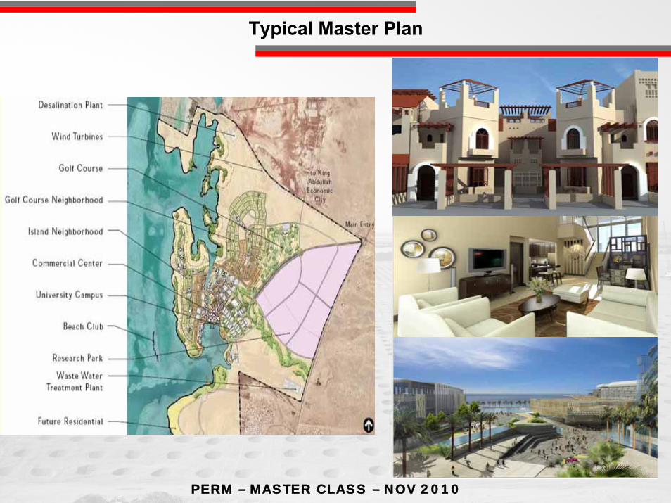
Typical Master Plan
PERM – MASTER CLASS – NOV 2010
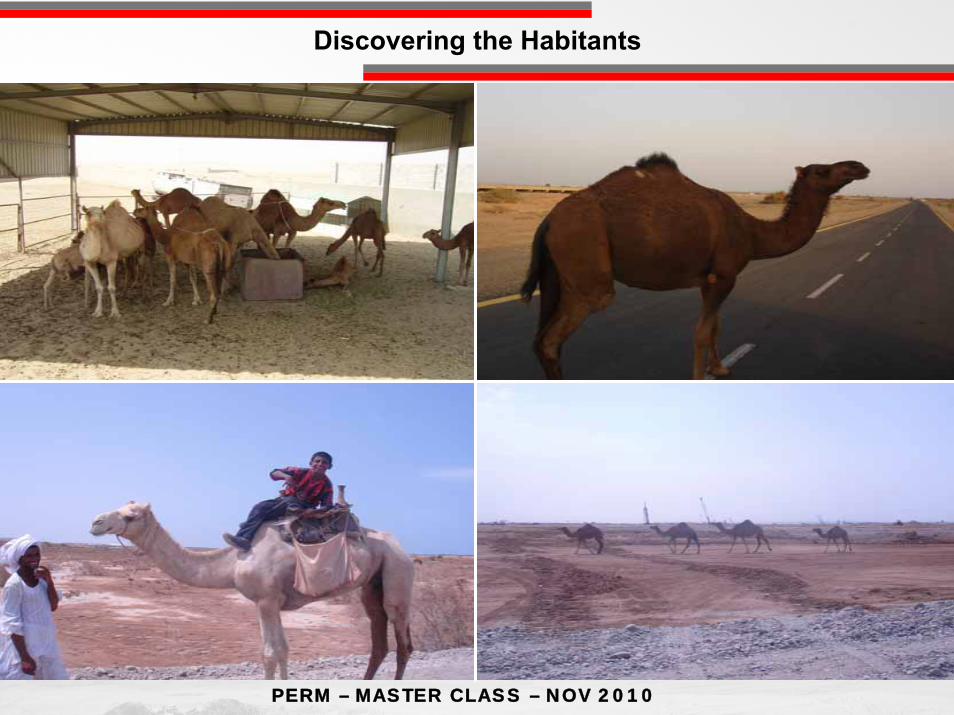
Discovering the Habitants
PERM – MASTER CLASS – NOV 2010
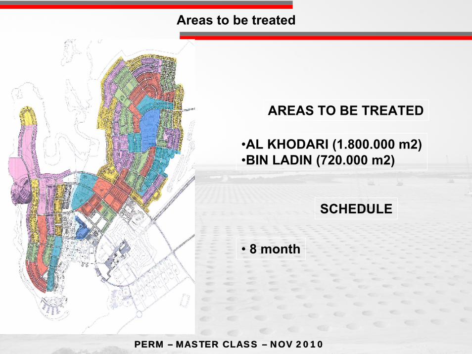
AREAS TO BE TREATED
•AL KHODARI (1.800.000 m2)•BIN LADIN (720.000 m2)
SCHEDULE
• 8 month
Areas to be treated
PERM – MASTER CLASS – NOV 2010
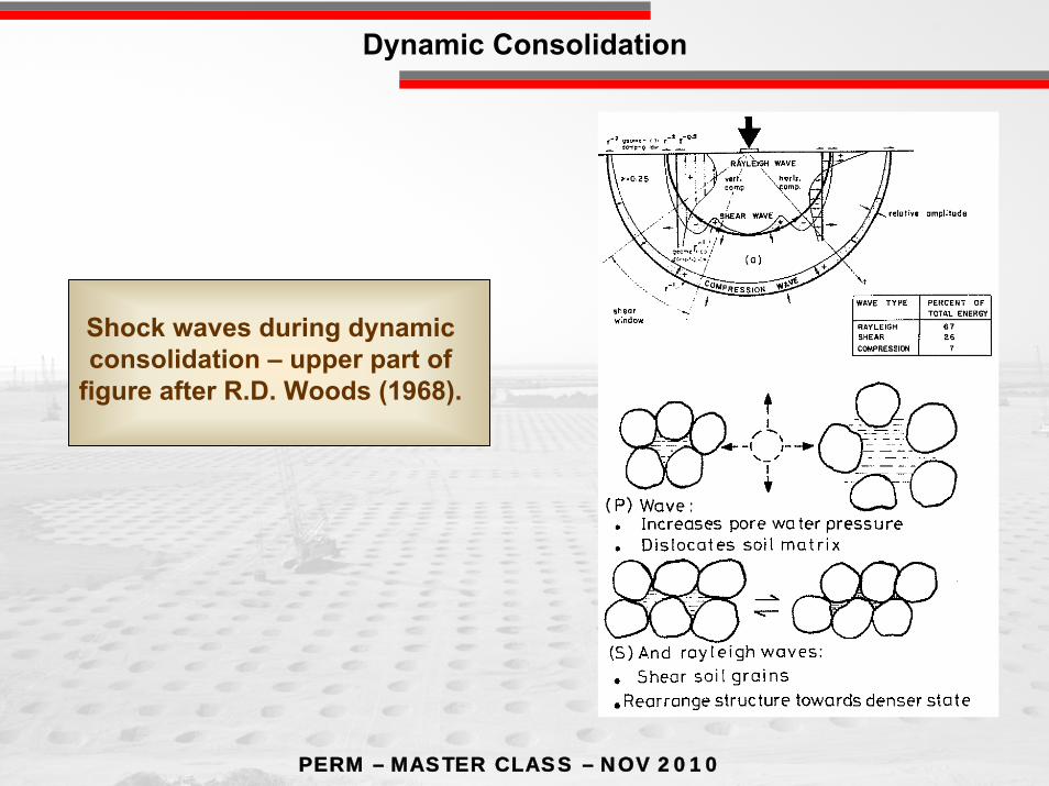
Shock waves during dynamic consolidation – upper part of
figure after R.D. Woods (1968).
Dynamic Consolidation

PERM – MASTER CLASS – NOV 2010
•Isolated footings up to 150 tons
•Bearing capacity 200 kPa
•Maximum footing settlement 25 mm
•Maximum differential settlement 1/500
•Footing location unknown at works stage
Specifications

PERM – MASTER CLASS – NOV 2010
+ 1.2
+ 2.52 meters arching layer
Depth of footing = 0.8mBelow G.L.
Working platform (gravelly sand)
Compressible layer from loosesand to very soft sabkah
Engineered fill
0 to 9 meters
σz = 200 kn/m²+ 4.0
150 TONS
Concept

PERM – MASTER CLASS – NOV 2010
The equation has been revised recently by Varaksin and Racinais (2009) as:
Where: f(z) is the improvement ratio at elevation (z); z is the depth in meters; NGL is the natural ground level; D is the depth of influence of dynamic consolidation; f1 is the maximum improvement ratio observed at ground surface and it is dimensionless. The value may be taken as f1 = 0.008E and E is the energy in tons-meter/m2; and f2 is the improvement ratio at the maximum depth of influence that can be achieved.
( ) ( ) 12
212 fNGLz
Dffzf +−
−=
(D) = C δ
where: C is the type of drop. Its value is given in Table. δ is a correction factor. δ = 0.9 for metastable soils, young fills, or very recent hydraulic fills and δ = 0.4 – 0.6 for sands.
Table Values of coefficient C in the equation
WH
Drop method
Free drop Rig drop Mechanical
winchHydraulic
winch
Double hydraulic
winch
C 1.0 0.89 0.75 0.64 0.5

PERM – MASTER CLASS – NOV 2010
NGL
GWT
BSL (variable)
FPL
> 2,
80
Working Platform
Soi
l Con
ditio
nsD
esig
n
WPL
0,80
> 4,
50
Preloading
DR (DynamicReplacement)
HDR (High EnergyDynamicReplacement) + surcharge
Selection of technique

PERM – MASTER CLASS – NOV 2010
0
+1
+2
+3
+4
+5
-5
-4
-3
-2
-1
-10
-9
-8
-7
-6
LAGOON FILLED BY SABKAH
RED SEA
ELEVATION (meters)
TYPICAL SITE CROSS SECTION OF UPPER DEPOSITS
+3
SITE ≅ 1,5 km
CORAL
BARRIER
LAYER USC w % % fines N QcBARS
FR % PLBARS
EPBARS
1 - SABKAH SM + ML 35-48 28-56 0-2 0-2 1,2-4 0,4-1,9 avr-17
2 - LOOSE SILTY SAND SM - 15-28 3-9 12-45 0,5-1,2 2,1-4 18-35
3 - CORAL - 26-35 - 6-12 - - 5,1-7,2 35-60
4 - LOOSE TO MED DENSE SAND SM - 12-37 3-18 15-80 0,5-1,8 4-12 28-85
2
4
4
Specifications
PERM – MASTER CLASS – NOV 2010
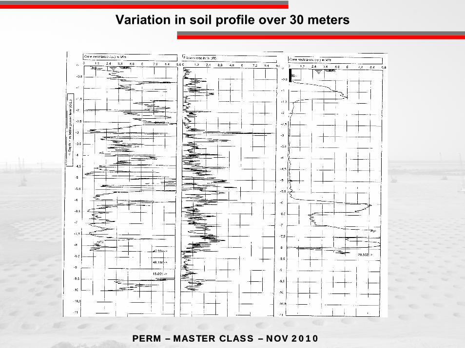
Variation in soil profile over 30 meters
PERM – MASTER CLASS – NOV 2010
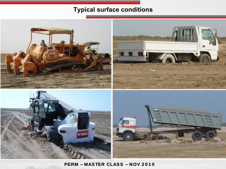
Typical surface conditions

PERM – MASTER CLASS – NOV 2010
PERM – MASTER CLASS – NOV 2010
KAUST KAUST
0
0.2
0.4
0.6
0.8
1
1.2
1.4
1.6
0 100 200 300 400 500
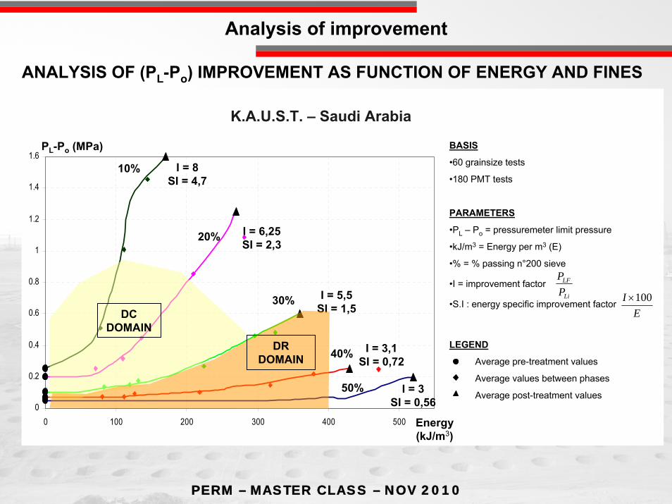
BASIS
•60 grainsize tests
•180 PMT tests
PARAMETERS
•PL – Po = pressuremeter limit pressure
•kJ/m3 = Energy per m3 (E)
•% = % passing n°200 sieve
•I = improvement factor
•S.I : energy specific improvement factor
LEGEND
Average pre-treatment values
Average values between phases
Average post-treatment values
I = 8SI = 4,7
I = 6,25SI = 2,3
I = 5,5SI = 1,5
I = 3,1SI = 0,72
I = 3SI = 0,56
Energy(kJ/m3)
PL-Po (MPa)
K.A.U.S.T. – Saudi Arabia
Li
LF
PP
EI 100×
DC DOMAIN
DR DOMAIN
10%
20%
30%
40%
50%
ANALYSIS OF (PL-Po) IMPROVEMENT AS FUNCTION OF ENERGY AND FINES
Analysis of improvement
PERM – MASTER CLASS – NOV 2010
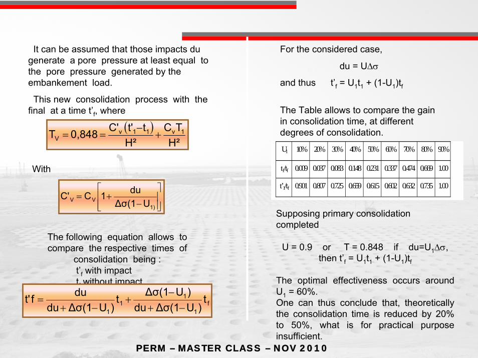
It can be assumed that those impacts du generate a pore pressure at least equal to the pore pressure generated by the embankement load.
This new consolidation process with the final at a time t’f, where
( )H²
TCH²
tt'C'0,848T 1v11vV +
−==
With
⎥⎥⎦
⎤
⎢⎢⎣
⎡
−+=
1)VV UΔσ(1
du1CC'
The following equation allows to compare the respective times of
consolidation being :t’f with impacttf without impact
f1
11
1
t)UΔσ(1du
)UΔσ(1t)UΔσ(1du
duft'−+
−+
−+=
For the considered case,
du = UΔσ
and thus t’f = U1t1 + (1-U1)tf
The Table allows to compare the gain in consolidation time, at different degrees of consolidation.
U1 10% 20% 30% 40% 50% 60% 70% 80% 90%
t1/tf 0.009 0.037 0.083 0.148 0.231 0.337 0.474 0.669 1.00
t’1/tf 0.901 0.807 0.725 0.659 0.615 0.602 0.632 0.735 1.00
Supposing primary consolidation completed
U = 0.9 or T = 0.848 if du=U1Δσ,then t’f = U1t1 + (1-U1)tf
The optimal effectiveness occurs around U1 = 60%.One can thus conclude that, theoretically the consolidation time is reduced by 20% to 50%, what is for practical purpose insufficient.

PERM – MASTER CLASS – NOV 2010
Dynamic surcharge
PERM – MASTER CLASS – NOV 2010

PERM – MASTER CLASS – NOV 2010
VIBROFLOTS
Amplitude 28 – 48mm

87PERM – MASTER CLASS – NOV 2010
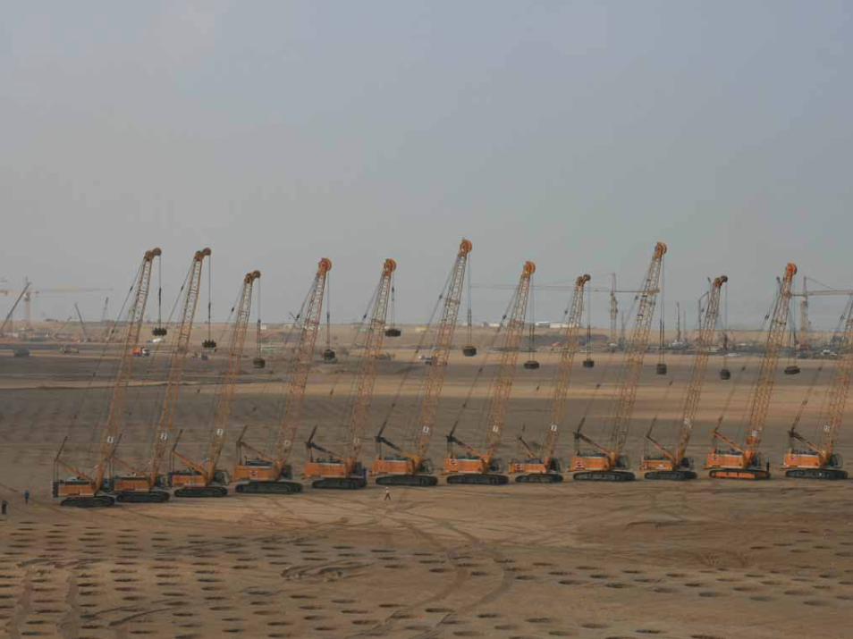
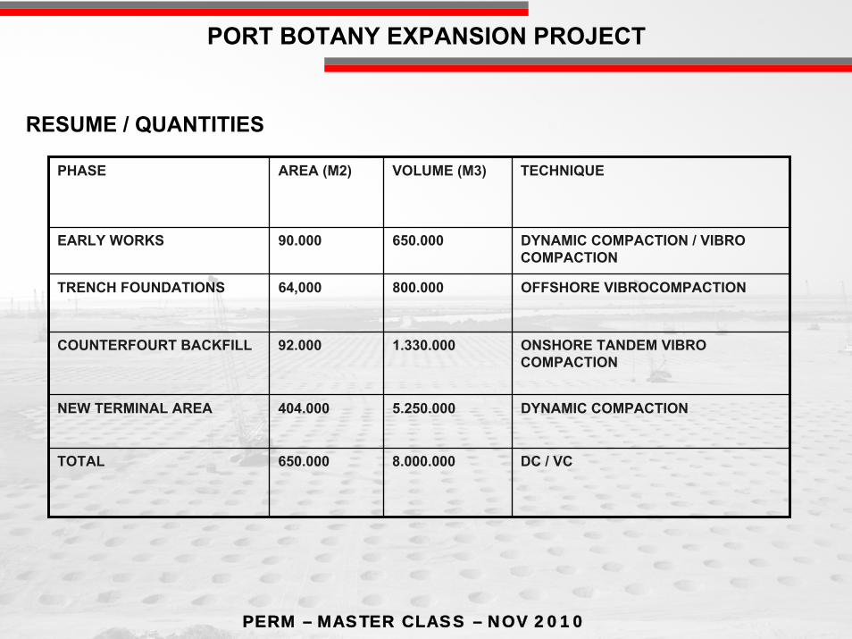
PORT BOTANY EXPANSION PROJECT
GROUND COMPACTION WORKS
PORT BOTANY EXPANSION PROJECT GROUND COMPACTION WORKS
EXISTING PORT
EXTENSION PORT

PERM – MASTER CLASS – NOV 2010
PORT BOTANY EXPANSION PROJECT
TRENCH FOUNDATIONS / COUNTERFOURT BACKFILL
EARLY WORKS
NEW TERMINAL AREA
600 M
1300 M
GROUND COMPACTION WORKS

PERM – MASTER CLASS – NOV 2010
GENERAL ARRAGEMENT COUNTERFORTS INCLUDING RECLAMATION
PORT BOTANY EXPANSION PROJECT
PERM – MASTER CLASS – NOV 2010
PORT BOTANY EXPANSION PROJECT
PHASE AREA (M2) VOLUME (M3) TECHNIQUE
EARLY WORKS 90.000 650.000 DYNAMIC COMPACTION / VIBRO COMPACTION
TRENCH FOUNDATIONS 64,000 800.000 OFFSHORE VIBROCOMPACTION
COUNTERFOURT BACKFILL 92.000 1.330.000 ONSHORE TANDEM VIBRO COMPACTION
NEW TERMINAL AREA 404.000 5.250.000 DYNAMIC COMPACTION
TOTAL 650.000 8.000.000 DC / VC
RESUME / QUANTITIES
PERM – MASTER CLASS – NOV 2010
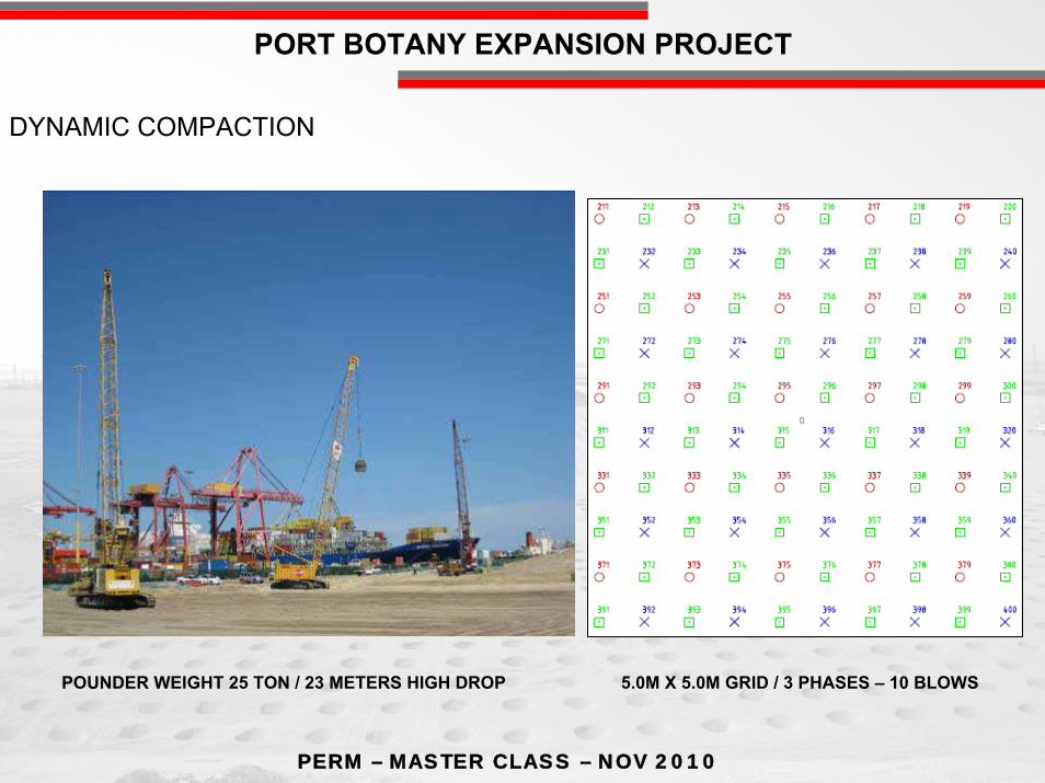
PORT BOTANY EXPANSION PROJECT
DYNAMIC COMPACTION
5.0M X 5.0M GRID / 3 PHASES – 10 BLOWSPOUNDER WEIGHT 25 TON / 23 METERS HIGH DROP

PERM – MASTER CLASS – NOV 2010
PORT BOTANY EXPANSION PROJECT
V48 REQUIRES WATER &
AIR FOR COMPACTIONUPLIFT STEPS 1.0M / 40 SEC EACH
LOAD OUT WHARF – VIBRO COMPACTION V48

PERM – MASTER CLASS – NOV 2010
PORT BOTANY EXPANSION PROJECT
VIEW OF LOAD OUT WHARF – DC / VC WORKING

PERM – MASTER CLASS – NOV 2010
PORT BOTANY EXPANSION PROJECT

PERM – MASTER CLASS – NOV 2010
PORT BOTANY EXPANSION PROJECT

PERM – MASTER CLASS – NOV 2010
PORT BOTANY EXPANSION PROJECT
1. Except for the upper 50cm, the combination of VC and DC satisfied the qc= 15 MPa (upper 0.5m requires surface roller compaction).
2. Enforced settlement: After VC – 47cm After DC – 27cm Total – 74 cm (~ 10% of treatment depth)
Compaction was less effective in this layer!
stiff clay
RESULTS
PERM – MASTER CLASS – NOV 2010
Cohesive soilPeat , clay …
Granular soil
Sand , fill
Without addedmaterials
With addedmaterials
1 Drainage 2 VAcuum
3 Dynamicconsolidation4 Vibroflottation
4 Dynamicreplacement
5 Stone columns6 CMC7 Jet Grouting8 Cement Mixing
Soil Improvement Techniques
PERM – MASTER CLASS – NOV 2010
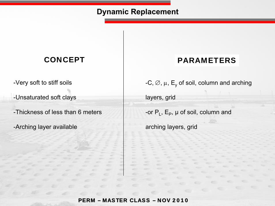
-Very soft to stiff soils
-Unsaturated soft clays
-Thickness of less than 6 meters
-Arching layer available
-C, ∅, μ, Ey of soil, column and arching
layers, grid
-or PL, EP, µ of soil, column and
arching layers, grid
CONCEPT PARAMETERS
Dynamic Replacement

PERM – MASTER CLASS – NOV 2010
Vibrator penetration Material feeding Vibration of material during
extraction
Principle of the technology - bottom feed with air tank
Stone Columns – Bottom Feed

PERM – MASTER CLASS – NOV 2010
Stone Columns – Bottom Feed
Stone Columnsbottom feed to 22 m depth
PERM – MASTER CLASS – NOV 2010
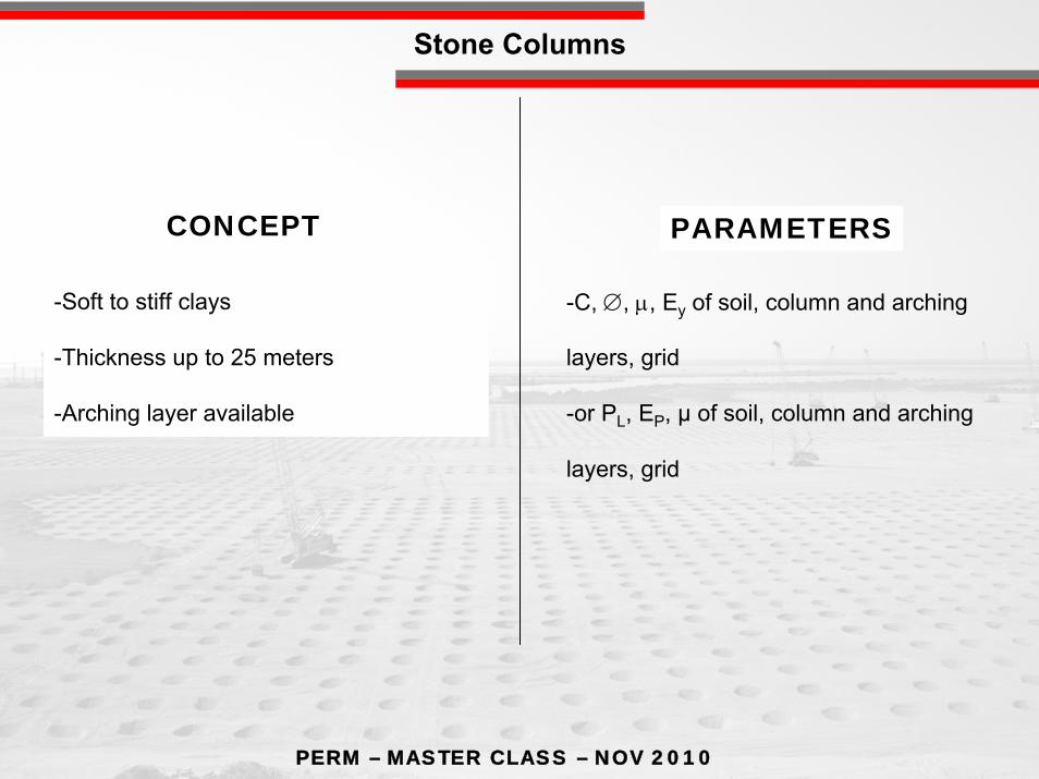
-Soft to stiff clays
-Thickness up to 25 meters
-Arching layer available
-C, ∅, μ, Ey of soil, column and arching
layers, grid
-or PL, EP, µ of soil, column and arching
layers, grid
CONCEPT PARAMETERS
Stone Columns
PERM – MASTER CLASS – NOV 2010
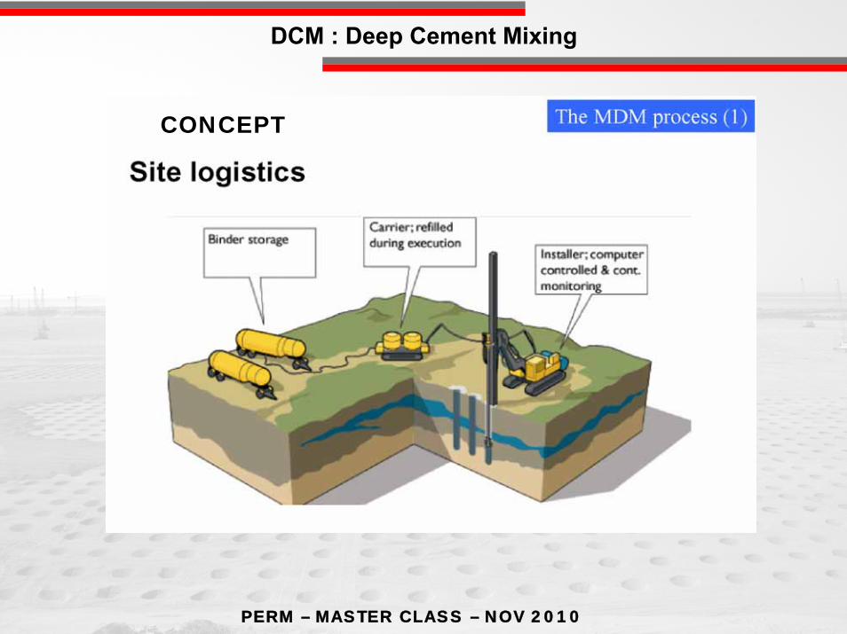
CONCEPT
DCM : Deep Cement Mixing

PERM – MASTER CLASS – NOV 2010
CMC – Execution
Soft soil
Groutflow
Fleet of specilized equipmentDisplacement auger => quasi no spoilHigh torque and pull down
Fully integrated grout flow control
PERM – MASTER CLASS – NOV 2010
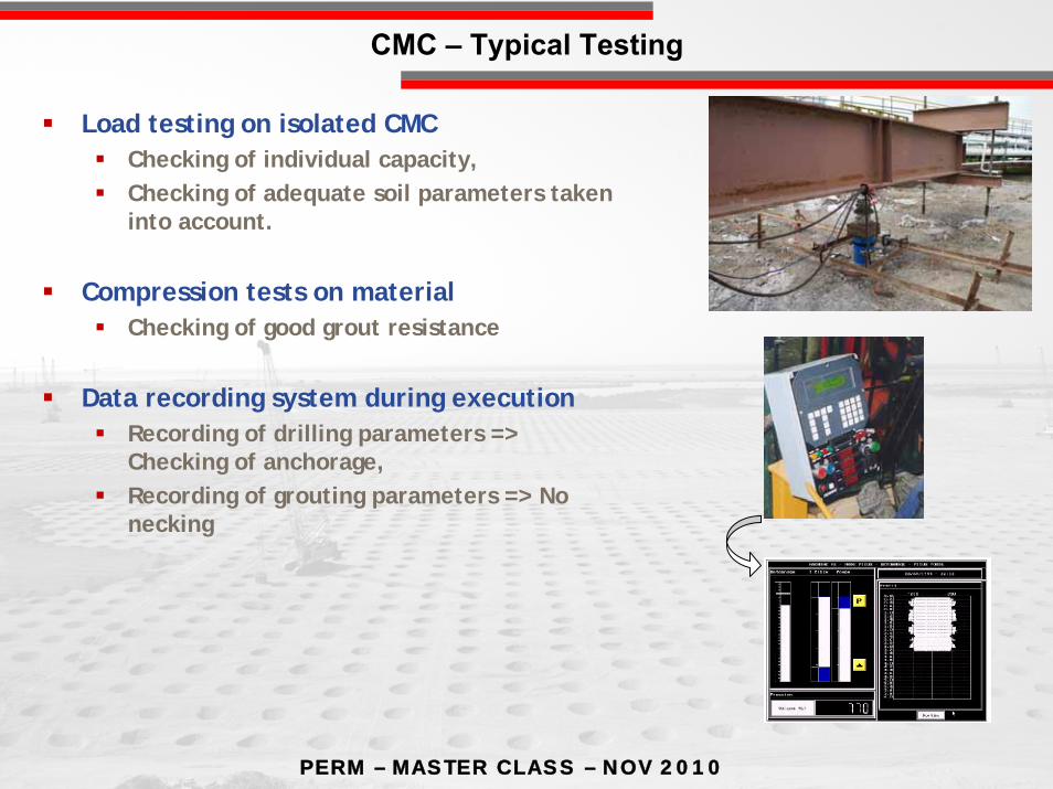
CMC – Typical Testing
Load testing on isolated CMCChecking of individual capacity,Checking of adequate soil parameters taken into account.
Compression tests on material Checking of good grout resistance
Data recording system during executionRecording of drilling parameters => Checking of anchorage,Recording of grouting parameters => No necking
PERM – MASTER CLASS – NOV 2010
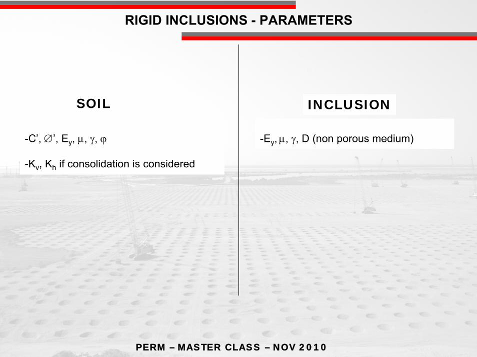
RIGID INCLUSIONS - PARAMETERS
-C’, ∅’, Ey, μ, γ, ϕ
-Kv, Kh if consolidation is considered
-Ey, μ, γ, D (non porous medium)
SOIL INCLUSION

PERM – MASTER CLASS – NOV 2010
CMC Principle
Stress concentration
CMC
Residual stressArch effect between the
columnsCMC
Transition layer
Create a composite material Soil + Rigid Inclusion (CMC) with:Increased bearing capacityIncreased elastic modulus
Transfer the load from structure to CMC network with a transition layer

PERM – MASTER CLASS – NOV 2010
CMC - Basic behavior under uniform load
Negative skin friction
Settlement
Positive skin friction
Soil
Column
Stress in the column
Neutralpoint
Negative skin friction allows to develop a good arching effect
Depth
PERM – MASTER CLASS – NOV 2010
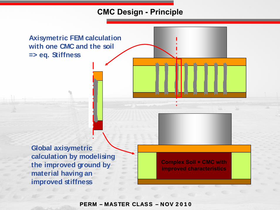
CMC Design - Principle
Complex Soil + CMC withimproved characteristics
Axisymetric FEM calculation with one CMC and the soil=> eq. Stiffness
Global axisymetric calculation by modelising the improved ground bymaterial having an improved stiffness
PERM – MASTER CLASS – NOV 2010
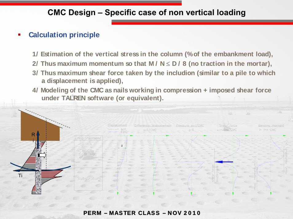
δ
CMC Design – Specific case of non vertical loading
Ri
Ti
Calculation principle
1/ Estimation of the vertical stress in the column (% of the embankment load),2/ Thus maximum momentum so that M / N ≤ D / 8 (no traction in the mortar),3/ Thus maximum shear force taken by the includion (similar to a pile to which
a displacement is applied),4/ Modeling of the CMC as nails working in compression + imposed shear force
under TALREN software (or equivalent).
PERM – MASTER CLASS – NOV 2010
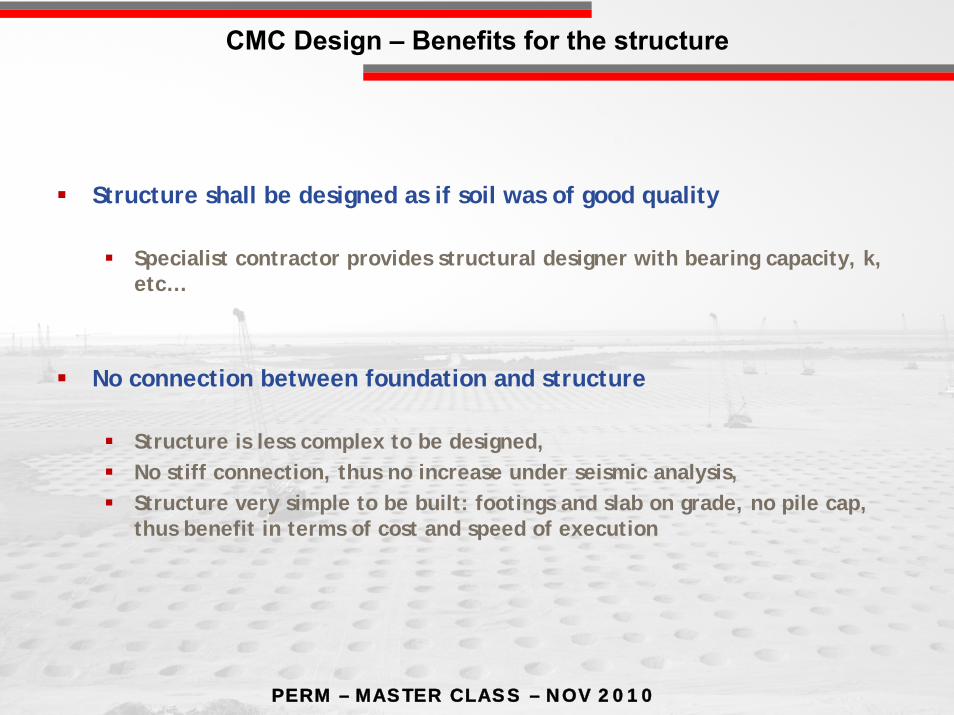
CMC Design – Benefits for the structure
Structure shall be designed as if soil was of good quality
Specialist contractor provides structural designer with bearing capacity, k, etc…
No connection between foundation and structure
Structure is less complex to be designed,No stiff connection, thus no increase under seismic analysis,Structure very simple to be built: footings and slab on grade, no pile cap, thus benefit in terms of cost and speed of execution
PERM – MASTER CLASS – NOV 2010
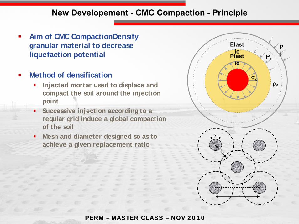
New Developement - CMC Compaction - Principle
ρf
Elastic
Plastic
σc
Pf
P0
rp
2.rc
a
Aim of CMC CompactionDensify granular material to decrease liquefaction potential
Method of densificationInjected mortar used to displace andcompact the soil around the injection pointSuccessive injection according to aregular grid induce a global compaction of the soil Mesh and diameter designed so as to achieve a given replacement ratio
PERM – MASTER CLASS – NOV 2010
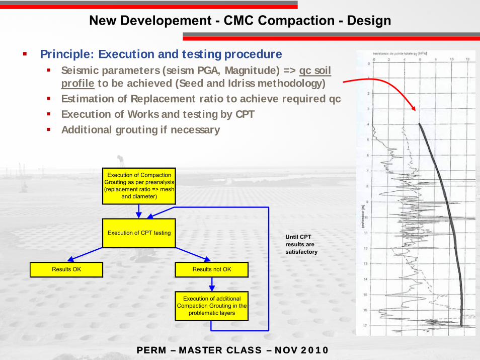
New Developement - CMC Compaction - Design
Results OK Results not OK
Execution of additional Compaction Grouting in the
problematic layers
Until CPT results are satisfactory
Execution of Compaction Grouting as per preanalysis (replacement ratio => mesh
and diameter)
Execution of CPT testing
Principle: Execution and testing procedureSeismic parameters (seism PGA, Magnitude) => qc soilprofile to be achieved (Seed and Idriss methodology)Estimation of Replacement ratio to achieve required qcExecution of Works and testing by CPTAdditional grouting if necessary

PERM – MASTER CLASS – NOV 2010
New Developement - CMC Compaction - Execution
Same type of equipment as for CMC
Soil displacement rig and Pump,
Key pointsQuality of grout (grain size distribution, workability, consistancy)Injection speed and successive phases
Final Testing = CPT
PERM – MASTER CLASS – NOV 2010
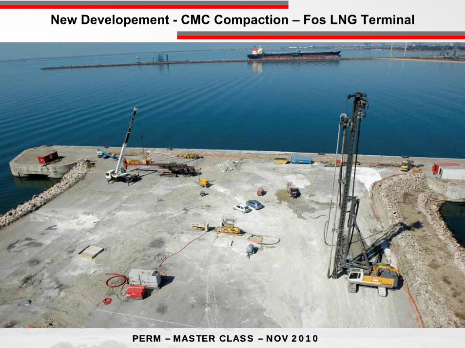
New Developement - CMC Compaction – Fos LNG Terminal
PERM – MASTER CLASS – NOV 2010
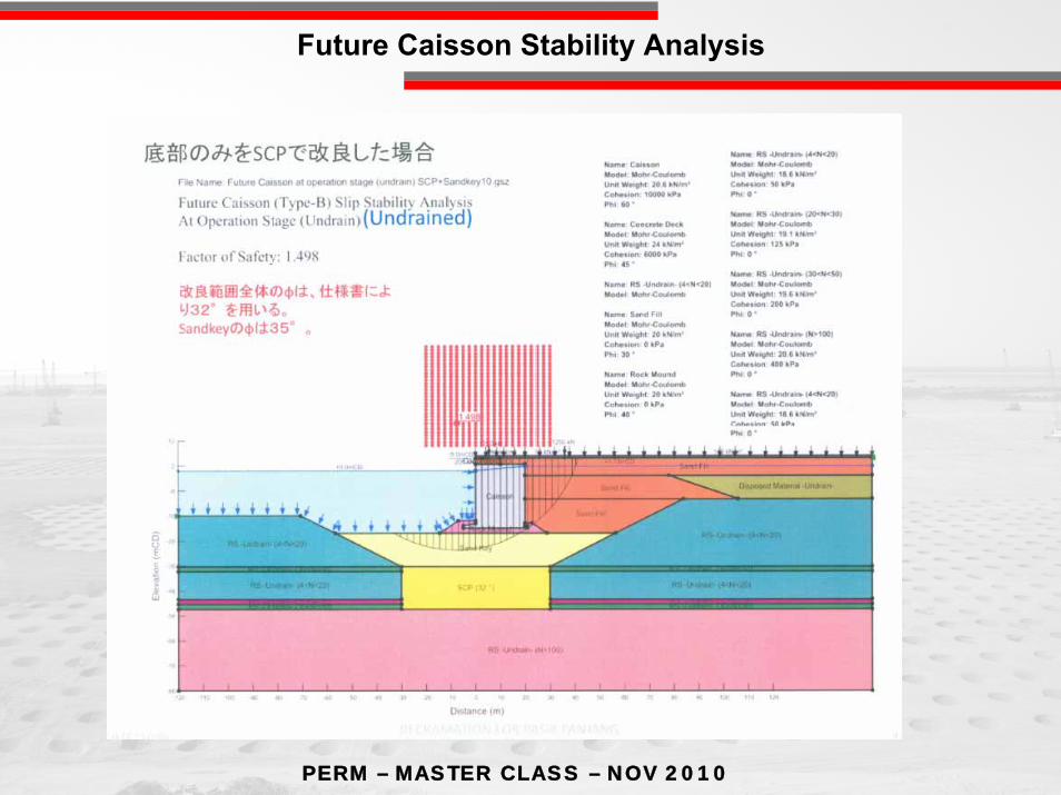
Future Caisson Stability Analysis
PERM – MASTER CLASS – NOV 2010
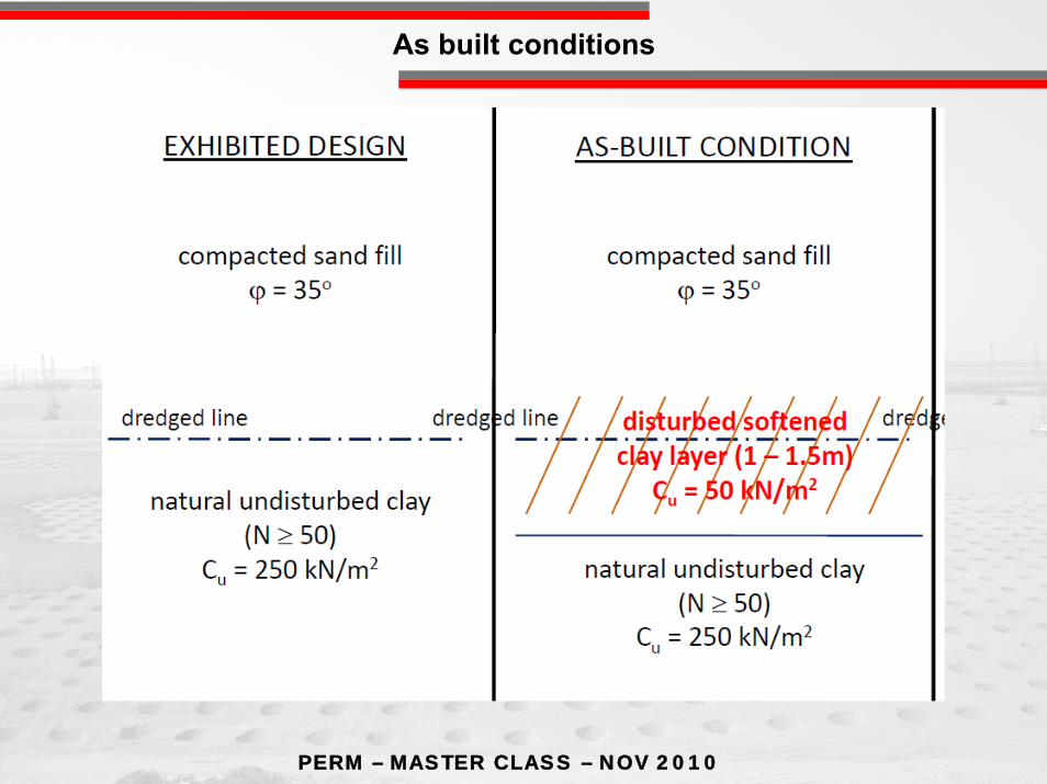
As built conditions
PERM – MASTER CLASS – NOV 2010
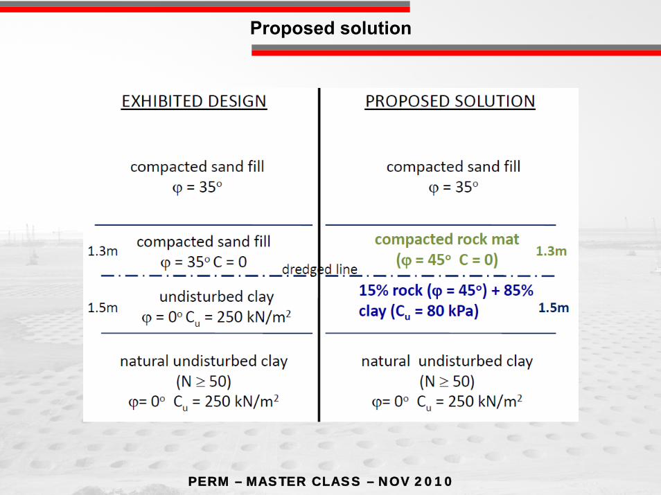
Proposed solution
Layer I
Layer II
15% rock (φ = 45°) + 85% clay (Cu = 50 kPa)

PERM – MASTER CLASS – NOV 2010
View of pounder construction
PERM – MASTER CLASS – NOV 2010
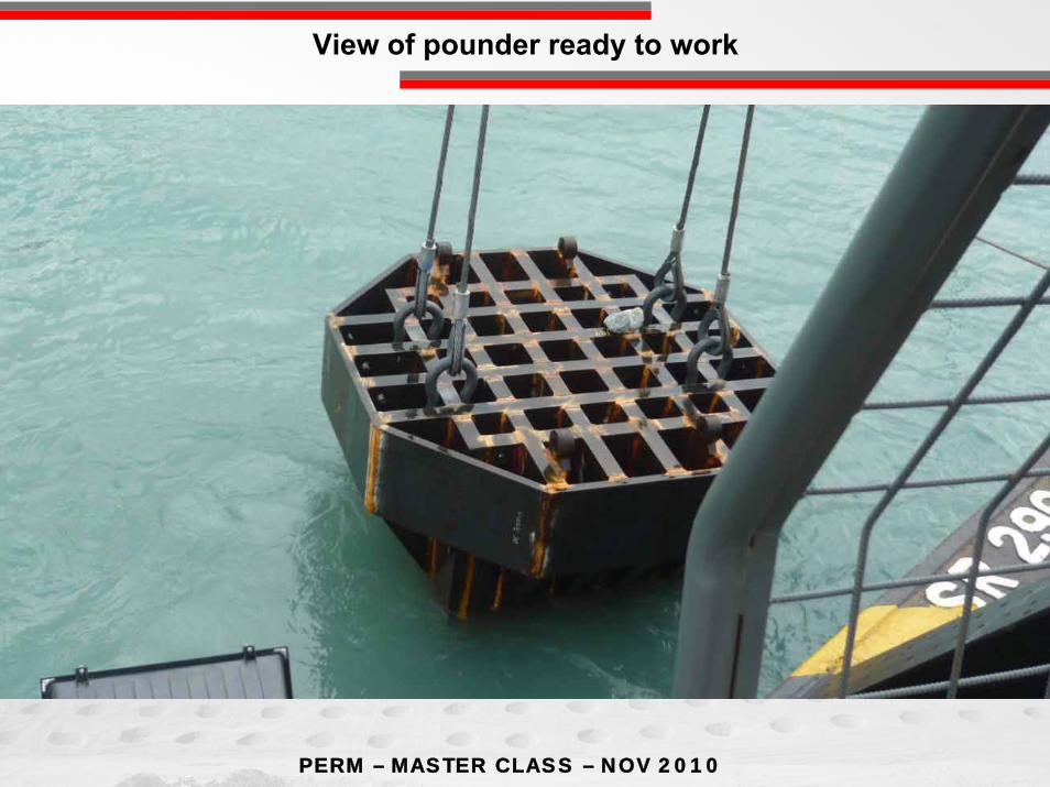
View of pounder ready to work

PERM – MASTER CLASS – NOV 2010
General SFT up

PERM – MASTER CLASS – NOV 2010
After compaction actual results
φ=48 degreeAr=22%C=0kPaColumn Dia=2.4m
φ=40 degree φ=40 degree
Cu=50kPa Cu=50kPa
Cu=250kPa
φ=48 degreeAr=22%C=0kPaColumn Dia=2.4m
φ=48 degreeAr=22%C=0kPaColumn Dia=2.4m1.3m
1.3m
0.2m
Original rock surface before compaction

122
ISSMGE
PERM – MASTER CLASS – November 16th, 2010
Nikolaï Semyonovitch MordvinovDerzhavin Gavriil Romanovitch