Computing robot internal/external wrenches by means of ... · PDF fileComputing robot...
8
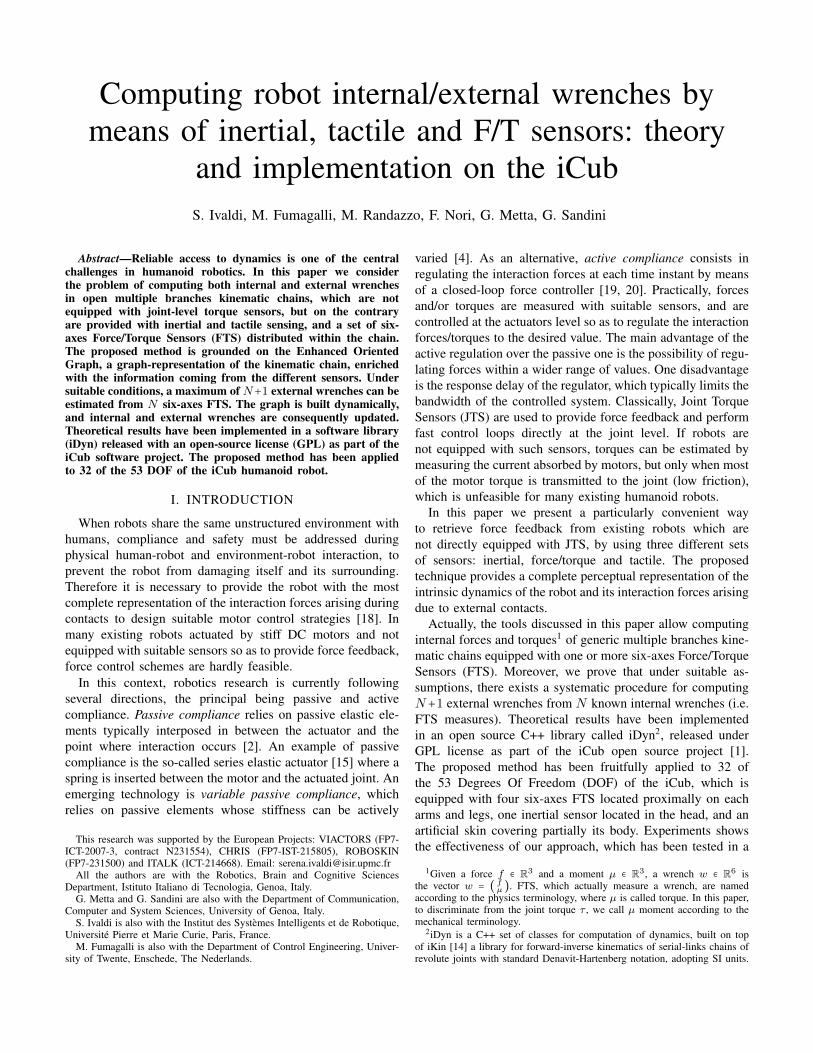
Computing robot internal/external wrenches by means of inertial, tactile and F/T sensors: theory and implementation on the iCub S. Ivaldi, M. Fumagalli, M. Randazzo, F. Nori, G. Metta, G. Sandini Abstract—Reliable access to dynamics is one of the central challenges in humanoid robotics. In this paper we consider the problem of computing both internal and external wrenches in open multiple branches kinematic chains, which are not equipped with joint-level torque sensors, but on the contrary are provided with inertial and tactile sensing, and a set of six- axes Force/Torque Sensors (FTS) distributed within the chain. The proposed method is grounded on the Enhanced Oriented Graph, a graph-representation of the kinematic chain, enriched with the information coming from the different sensors. Under suitable conditions, a maximum of N +1 external wrenches can be estimated from N six-axes FTS. The graph is built dynamically, and internal and external wrenches are consequently updated. Theoretical results have been implemented in a software library (iDyn) released with an open-source license (GPL) as part of the iCub software project. The proposed method has been applied to 32 of the 53 DOF of the iCub humanoid robot. I. INTRODUCTION When robots share the same unstructured environment with humans, compliance and safety must be addressed during physical human-robot and environment-robot interaction, to prevent the robot from damaging itself and its surrounding. Therefore it is necessary to provide the robot with the most complete representation of the interaction forces arising during contacts to design suitable motor control strategies [18]. In many existing robots actuated by stiff DC motors and not equipped with suitable sensors so as to provide force feedback, force control schemes are hardly feasible. In this context, robotics research is currently following several directions, the principal being passive and active compliance. Passive compliance relies on passive elastic ele- ments typically interposed in between the actuator and the point where interaction occurs [2]. An example of passive compliance is the so-called series elastic actuator [15] where a spring is inserted between the motor and the actuated joint. An emerging technology is variable passive compliance, which relies on passive elements whose stiffness can be actively This research was supported by the European Projects: VIACTORS (FP7- ICT-2007-3, contract N231554), CHRIS (FP7-IST-215805), ROBOSKIN (FP7-231500) and ITALK (ICT-214668). Email: [email protected] All the authors are with the Robotics, Brain and Cognitive Sciences Department, Istituto Italiano di Tecnologia, Genoa, Italy. G. Metta and G. Sandini are also with the Department of Communication, Computer and System Sciences, University of Genoa, Italy. S. Ivaldi is also with the Institut des Syst` emes Intelligents et de Robotique, Universit´ e Pierre et Marie Curie, Paris, France. M. Fumagalli is also with the Department of Control Engineering, Univer- sity of Twente, Enschede, The Nederlands. varied [4]. As an alternative, active compliance consists in regulating the interaction forces at each time instant by means of a closed-loop force controller [19, 20]. Practically, forces and/or torques are measured with suitable sensors, and are controlled at the actuators level so as to regulate the interaction forces/torques to the desired value. The main advantage of the active regulation over the passive one is the possibility of regu- lating forces within a wider range of values. One disadvantage is the response delay of the regulator, which typically limits the bandwidth of the controlled system. Classically, Joint Torque Sensors (JTS) are used to provide force feedback and perform fast control loops directly at the joint level. If robots are not equipped with such sensors, torques can be estimated by measuring the current absorbed by motors, but only when most of the motor torque is transmitted to the joint (low friction), which is unfeasible for many existing humanoid robots. In this paper we present a particularly convenient way to retrieve force feedback from existing robots which are not directly equipped with JTS, by using three different sets of sensors: inertial, force/torque and tactile. The proposed technique provides a complete perceptual representation of the intrinsic dynamics of the robot and its interaction forces arising due to external contacts. Actually, the tools discussed in this paper allow computing internal forces and torques 1 of generic multiple branches kine- matic chains equipped with one or more six-axes Force/Torque Sensors (FTS). Moreover, we prove that under suitable as- sumptions, there exists a systematic procedure for computing N + 1 external wrenches from N known internal wrenches (i.e. FTS measures). Theoretical results have been implemented in an open source C++ library called iDyn 2 , released under GPL license as part of the iCub open source project [1]. The proposed method has been fruitfully applied to 32 of the 53 Degrees Of Freedom (DOF) of the iCub, which is equipped with four six-axes FTS located proximally on each arms and legs, one inertial sensor located in the head, and an artificial skin covering partially its body. Experiments shows the effectiveness of our approach, which has been tested in a 1 Given a force f ∈ R 3 and a moment μ ∈ R 3 , a wrench w ∈ R 6 is the vector w = f μ . FTS, which actually measure a wrench, are named according to the physics terminology, where μ is called torque. In this paper, to discriminate from the joint torque τ , we call μ moment according to the mechanical terminology. 2 iDyn is a C++ set of classes for computation of dynamics, built on top of iKin [14] a library for forward-inverse kinematics of serial-links chains of revolute joints with standard Denavit-Hartenberg notation, adopting SI units.
-
Upload
hoangtuyen -
Category
Documents
-
view
215 -
download
0
Transcript of Computing robot internal/external wrenches by means of ... · PDF fileComputing robot...
Computing robot internal/external wrenches bymeans of inertial, tactile and F/T sensors: theory
and implementation on the iCubS. Ivaldi, M. Fumagalli, M. Randazzo, F. Nori, G. Metta, G. Sandini
Abstract—Reliable access to dynamics is one of the centralchallenges in humanoid robotics. In this paper we considerthe problem of computing both internal and external wrenchesin open multiple branches kinematic chains, which are notequipped with joint-level torque sensors, but on the contraryare provided with inertial and tactile sensing, and a set of six-axes Force/Torque Sensors (FTS) distributed within the chain.The proposed method is grounded on the Enhanced OrientedGraph, a graph-representation of the kinematic chain, enrichedwith the information coming from the different sensors. Undersuitable conditions, a maximum of N+1 external wrenches can beestimated from N six-axes FTS. The graph is built dynamically,and internal and external wrenches are consequently updated.Theoretical results have been implemented in a software library(iDyn) released with an open-source license (GPL) as part of theiCub software project. The proposed method has been appliedto 32 of the 53 DOF of the iCub humanoid robot.
I. INTRODUCTION
When robots share the same unstructured environment withhumans, compliance and safety must be addressed duringphysical human-robot and environment-robot interaction, toprevent the robot from damaging itself and its surrounding.Therefore it is necessary to provide the robot with the mostcomplete representation of the interaction forces arising duringcontacts to design suitable motor control strategies [18]. Inmany existing robots actuated by stiff DC motors and notequipped with suitable sensors so as to provide force feedback,force control schemes are hardly feasible.
In this context, robotics research is currently followingseveral directions, the principal being passive and activecompliance. Passive compliance relies on passive elastic ele-ments typically interposed in between the actuator and thepoint where interaction occurs [2]. An example of passivecompliance is the so-called series elastic actuator [15] where aspring is inserted between the motor and the actuated joint. Anemerging technology is variable passive compliance, whichrelies on passive elements whose stiffness can be actively
This research was supported by the European Projects: VIACTORS (FP7-ICT-2007-3, contract N231554), CHRIS (FP7-IST-215805), ROBOSKIN(FP7-231500) and ITALK (ICT-214668). Email: [email protected]
All the authors are with the Robotics, Brain and Cognitive SciencesDepartment, Istituto Italiano di Tecnologia, Genoa, Italy.
G. Metta and G. Sandini are also with the Department of Communication,Computer and System Sciences, University of Genoa, Italy.
S. Ivaldi is also with the Institut des Systemes Intelligents et de Robotique,Universite Pierre et Marie Curie, Paris, France.
M. Fumagalli is also with the Department of Control Engineering, Univer-sity of Twente, Enschede, The Nederlands.
varied [4]. As an alternative, active compliance consists inregulating the interaction forces at each time instant by meansof a closed-loop force controller [19, 20]. Practically, forcesand/or torques are measured with suitable sensors, and arecontrolled at the actuators level so as to regulate the interactionforces/torques to the desired value. The main advantage of theactive regulation over the passive one is the possibility of regu-lating forces within a wider range of values. One disadvantageis the response delay of the regulator, which typically limits thebandwidth of the controlled system. Classically, Joint TorqueSensors (JTS) are used to provide force feedback and performfast control loops directly at the joint level. If robots arenot equipped with such sensors, torques can be estimated bymeasuring the current absorbed by motors, but only when mostof the motor torque is transmitted to the joint (low friction),which is unfeasible for many existing humanoid robots.
In this paper we present a particularly convenient wayto retrieve force feedback from existing robots which arenot directly equipped with JTS, by using three different setsof sensors: inertial, force/torque and tactile. The proposedtechnique provides a complete perceptual representation of theintrinsic dynamics of the robot and its interaction forces arisingdue to external contacts.
Actually, the tools discussed in this paper allow computinginternal forces and torques1 of generic multiple branches kine-matic chains equipped with one or more six-axes Force/TorqueSensors (FTS). Moreover, we prove that under suitable as-sumptions, there exists a systematic procedure for computingN+1 external wrenches from N known internal wrenches (i.e.FTS measures). Theoretical results have been implementedin an open source C++ library called iDyn2, released underGPL license as part of the iCub open source project [1].The proposed method has been fruitfully applied to 32 ofthe 53 Degrees Of Freedom (DOF) of the iCub, which isequipped with four six-axes FTS located proximally on eacharms and legs, one inertial sensor located in the head, and anartificial skin covering partially its body. Experiments showsthe effectiveness of our approach, which has been tested in a
1Given a force f ∈ R3 and a moment µ ∈ R3, a wrench w ∈ R6 isthe vector w = (
fµ ). FTS, which actually measure a wrench, are named
according to the physics terminology, where µ is called torque. In this paper,to discriminate from the joint torque τ , we call µ moment according to themechanical terminology.
2iDyn is a C++ set of classes for computation of dynamics, built on topof iKin [14] a library for forward-inverse kinematics of serial-links chains ofrevolute joints with standard Denavit-Hartenberg notation, adopting SI units.
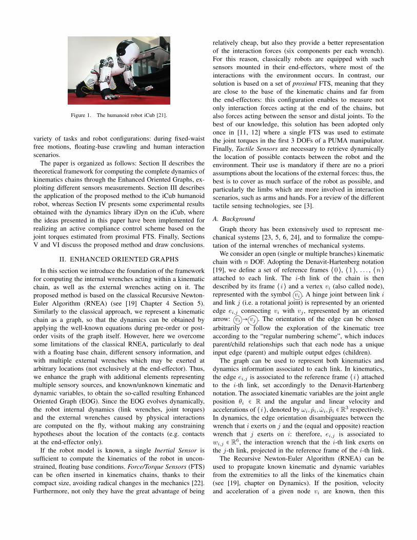
Figure 1. The humanoid robot iCub [21].
variety of tasks and robot configurations: during fixed-waistfree motions, floating-base crawling and human interactionscenarios.
The paper is organized as follows: Section II describes thetheoretical framework for computing the complete dynamics ofkinematics chains through the Enhanced Oriented Graphs, ex-ploiting different sensors measurements. Section III describesthe application of the proposed method to the iCub humanoidrobot, whereas Section IV presents some experimental resultsobtained with the dynamics library iDyn on the iCub, wherethe ideas presented in this paper have been implemented forrealizing an active compliance control scheme based on thejoint torques estimated from proximal FTS. Finally, SectionsV and VI discuss the proposed method and draw conclusions.
II. ENHANCED ORIENTED GRAPHS
In this section we introduce the foundation of the frameworkfor computing the internal wrenches acting within a kinematicchain, as well as the external wrenches acting on it. Theproposed method is based on the classical Recursive Newton-Euler Algorithm (RNEA) (see [19] Chapter 4 Section 5).Similarly to the classical approach, we represent a kinematicchain as a graph, so that the dynamics can be obtained byapplying the well-known equations during pre-order or post-order visits of the graph itself. However, here we overcomesome limitations of the classical RNEA, particularly to dealwith a floating base chain, different sensory information, andwith multiple external wrenches which may be exerted atarbitrary locations (not exclusively at the end-effector). Thus,we enhance the graph with additional elements representingmultiple sensory sources, and known/unknown kinematic anddynamic variables, to obtain the so-called resulting EnhancedOriented Graph (EOG). Since the EOG evolves dynamically,the robot internal dynamics (link wrenches, joint torques)and the external wrenches caused by physical interactionsare computed on the fly, without making any constraininghypotheses about the location of the contacts (e.g. contactsat the end-effector only).
If the robot model is known, a single Inertial Sensor issufficient to compute the kinematics of the robot in uncon-strained, floating base conditions. Force/Torque Sensors (FTS)can be often inserted in kinematics chains, thanks to theircompact size, avoiding radical changes in the mechanics [22].Furthermore, not only they have the great advantage of being
relatively cheap, but also they provide a better representationof the interaction forces (six components per each wrench).For this reason, classically robots are equipped with suchsensors mounted in their end-effectors, where most of theinteractions with the environment occurs. In contrast, oursolution is based on a set of proximal FTS, meaning that theyare close to the base of the kinematic chains and far fromthe end-effectors: this configuration enables to measure notonly interaction forces acting at the end of the chains, butalso forces acting between the sensor and distal joints. To thebest of our knowledge, this solution has been adopted onlyonce in [11, 12] where a single FTS was used to estimatethe joint torques in the first 3 DOFs of a PUMA manipulator.Finally, Tactile Sensors are necessary to retrieve dynamicallythe location of possible contacts between the robot and theenvironment. Their use is mandatory if there are no a prioriassumptions about the locations of the external forces: thus, thebest is to cover as much surface of the robot as possible, andparticularly the limbs which are more involved in interactionscenarios, such as arms and hands. For a review of the differenttactile sensing technologies, see [3].
A. Background
Graph theory has been extensively used to represent me-chanical systems [23, 5, 6, 24], and to formalize the compu-tation of the internal wrenches of mechanical systems.
We consider an open (single or multiple branches) kinematicchain with n DOF. Adopting the Denavit-Hartenberg notation[19], we define a set of reference frames ⟨0 ⟩, ⟨1 ⟩, . . . , ⟨n ⟩attached to each link. The i-th link of the chain is thendescribed by its frame ⟨ i ⟩ and a vertex vi (also called node),represented with the symbol vi . A hinge joint between link iand link j (i.e. a rotational joint) is represented by an orientededge ei,j connecting vi with vj , represented by an orientedarrow: vi → vj . The orientation of the edge can be chosenarbitrarily or follow the exploration of the kinematic treeaccording to the “regular numbering scheme”, which inducesparent/child relationships such that each node has a uniqueinput edge (parent) and multiple output edges (children).
The graph can be used to represent both kinematics anddynamics information associated to each link. In kinematics,the edge ei,j is associated to the reference frame ⟨ i ⟩ attachedto the i-th link, set accordingly to the Denavit-Hartenbergnotation. The associated kinematic variables are the joint angleposition θi ∈ R and the angular and linear velocity andaccelerations of ⟨ i ⟩, denoted by ωi, pi, ωi, pi ∈ R3 respectively.In dynamics, the edge orientation disambiguates between thewrench that i exerts on j and the (equal and opposite) reactionwrench that j exerts on i: therefore, ei,j is associated towi,j ∈ R6, the interaction wrench that the i-th link exerts onthe j-th link, projected in the reference frame of the i-th link.
The Recursive Newton-Euler Algorithm (RNEA) can beused to propagate known kinematic and dynamic variablesfrom the extremities to all the links of the kinematics chain(see [19], chapter on Dynamics). If the position, velocityand acceleration of a given node vi are known, then this
information can be propagated through the Newton-Eulerkinematic step to all the nodes connected to vi exploitingthe joint position/velocity measurements/acceleration measure-ments. The well-known equations can be iterated to retrievethe i-th link angular velocity and acceleration (ωi, ωi) andlinear acceleration (pi) from the analogous base information(ω0, ω0, p0):
ωi+1 = ωi + θi+1zi,
ωi+1 = ωi + θi+1zi + θi+1ωi × zi,pi+1 = pi + ωi × ri,i+1 + ωi+1 × (ωi+1 × ri,i+1),
(1)
where zi is the z-axis of ⟨ i ⟩. That is, we propagate the kine-matic information from the base to the end-effector, visitingall the nodes moving from one node to the next following theedges. The internal dynamics of the manipulator can be studiedas well: if the dynamical parameters of the system are known(mass mi, inertia Ii, center of mass Ci), we can propagateknowledge of the wrenches applied at the end-effector (fn+1,µn+1) to the base frame of the manipulator so as to retrieveforces and moments fi, µi up to f0, µ0.
fi = fi+1 +mipCi ,
µi = µi+1 − fi × ri−1,Ci + fi+1 × ri,Ci + Iiωi+
+ ωi × (Iiωi),
(2)
where: pCi = pi + ωi × ri,Ci + ωi × (ωi × ri,Ci).Analogous considerations can be extended to multiple
branches open kinematic chains (also known as kinematic trees[6]). In that case, the kinematic Newton-Euler computationcan be performed by assuming that angular velocity andacceleration (ωi, ωi) and linear acceleration (pi) are knownfor at least one node of the graph. This information can thenbe propagated to the other nodes, by progressively movingfrom that node (usually the base) to all the other nodes of thegraph, i.e. from vj to vk using the oriented edge ej,k (or ek,j).
Similarly, the wrenches of the system can be computed bypropagating the information from one edge to the other. How-ever, in the classical RNEA initialization is always performedat the end-effector, thus following a unique order in visitingthe graph. With the EOG framework, we overcome theselimitations, and furthermore we give the possibility to includedifferent sources of dynamic information, with a genericprocedure to build dynamically the spanning tree from thegraph description of the dynamics, taking into account knowns(e.g. measured wrenches) and unknowns (e.g. wrenches to beestimated) of the system.
B. Enhanced Oriented Graphs
Whatever the orientation of the graph and the set of re-cursive equations used to propagate kinematics and dynamics,some initial information must be set to initialize the compu-tations. When we have measurements of kinematic variables(by means of suitable gyroscopes and/or accelerometers) andapplied wrenches (by means of 6-axes FT sensors), the graphrepresentation of the kinematic chain can be enriched, usinga specific set of symbols. The graph with this additionalinformation is called Enhanced Oriented Graph (EOG).
v0
v0
v1
v1
vn
vn
〈0 〉
〈0 〉
〈1 〉
〈1 〉
〈n 〉
〈n 〉
e0,1
e0,1
en−1,n
en−1,n
e1,2
e1,2
fn+1 = 0µn+1 = 0
f0 =?µ0 =?
ωn+1 =?ωn+1 =?pn+1 =?
ω0 = 0ω0 = 0p0
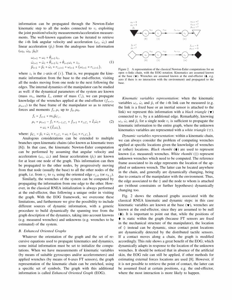
Figure 2. A representation of the classical Newton-Euler computations for anopen n-links chain, with the EOG notation. Kinematics are assumed knownat the base (▼). Wrenches are assumed known at the end-effector (⧫, e.g.zero if there is no interaction with the environment) and propagated to thebase.
Kinematic variables representation: when the kinematicvariables ωi, ωi and pi of the i-th link can be measured (e.g.the link is a fixed base or an inertial sensor is attached to thelink) we represent this information with a black triangle (▼)connected to vi by a n additional edge. Remarkably, knowingωi, ωi and pi for a single node vi is sufficient to propagate thekinematic information to the entire graph, where the unknownkinematics variables are represented with a white triangle (▽).
Dynamic variables representation: within a kinematic chain,we can always consider the problem of computing wrenchesapplied at specific locations given the knowledge of wrenchesat (other) locations. Black rhombi (⧫) are used to representknown (i.e. measured) wrenches. White rhombi (◊) representunknown wrenches which need to be computed. The referenceframe associated to its edge represents the location of the ap-plied or unknown wrench. The latter can be located anywherein the chain, and generally are dynamically changing, beingdue to contacts of the manipulator with the environment. Thus,the edge associated to the ◊ and the node to whom is attachedare (without constraints or further hypotheses) dynamicallychanging too.
Fig. 2 shows the enhanced graphs associated with theclassical RNEA kinematic and dynamic steps: in this casekinematic variables are known at the base (▼), wrenches areknown at the end-effector, since they are assumed to be null(⧫). It is important to point out that, while the positions of⧫ is static within the graph (because FT sensors are fixedin the mechanical structure of the manipulator), the locationof ◊ instead can be dynamic, since contact point locationsare dynamically detected by the distributed tactile sensors.If a contact moves along a chain, the graph is modifiedaccordingly. This rule shows a great benefit of the EOG; whichdynamically adapts in response to the location of the unknownwrenches. It should be noticed that in absence of the artificialskin, the EOG rule can still be applied, if other methods forestimating external forces locations are used [8]. However, ifit is not possible to retrieve the point of contact, the latter canbe assumed fixed at certain positions, e.g. the end-effector,where the most interaction is more likely to happen.

Figure 3. The graph shows how to insert a FTS into an EOG. The nodeon which the sensor is attached (highlighted), is practically divided into twosub-nodes, each corresponding to the physical sub-link created after cuttingthe link with the FTS. The graph is then divided into two sub-graphs and two⧫ (known wrenches corresponding to the sensor measurement) are connectedto the sub-nodes.
C. Representing FT measurements in a graph
The dynamic information from a 6-axes FTS can be insertedin the EOG representing the kinematic chain: the graph isdivided into two sub-graphs, and two ⧫ (i.e. two knownwrenches), one on each sub-graph, are used to representthe FT measure. In detail, suppose that an FTS is placedin the iS-th link. Let ⟨s ⟩ be the frame associated to thesensor. The sensor “divides” the link iS into two “sub-links”(hereafter denoted forward and backward sub-links). Thereforethe sensor measures the wrench exerted by the “forward” sub-link to the “backward” sub-link (this will be represented by afirst rhomboidal node). However, a wrench equal and oppositeto the sensor measurement is also exerted by the “backward”sub-link to the “forward” sub-link (this will be representedby a second rhomboidal node). Under these considerations,the FTS within a link is represented by splitting the nodeassociated to the link into two sub-nodes, represented by adouble circled node in the EOG symbolism. A sub-node hassuitable dynamical properties, since it corresponds to a ”sub-link“, i.e. to a portion of the original link which is physicallycut after the insertion of the FTS. As an example, considerthe iS-th link divided in two halves by an FTS: mass miS
is divided in mFiS
and mBiS
, and the original Center Of Mass(COM) CiS is replaced by two COM, CF
iSand CB
iSfor the
two sub-links. The overall procedure is shown in Fig. 3.
D. Computing the system dynamics from FTS measures
We now describe how to solve the dynamics of an open(multiple branches) chain exploiting the information from asingle inertial sensor and multiple FTS. The fundamental stepconsists in enhancing the oriented graph adding the known andunknown kinematics and dynamics variables within the chain,and in particular to split the graph into two subgraphs anytimea FTS is inserted. External forces can be computed accuratelyif their contact location is measured by suitable tactile sensorsor otherwise known a priori. Given a graph description of thechain, we perform the following operations to enhance thegraph:
1) insert a ▼ and an edge directed to the link where theinertial sensor is attached to, to represent its measure-ments
2) insert a ▽ and an edge directed to each “terminal”node3) for each FTS define the sub-links nodes (with suitable
dynamical properties); define two ⧫ associated to the
sensor measurements, and connect them to the sub-nodesas described in the procedure in Fig. 3;
4) for each unknown wrench, acting on the generic i-thlink, insert a ◊ with an associated edge connected to vi;
5) rearrange each subgraph so that each ◊ is the root of atree: for each leaf node (each node connected to onlyanother node) insert a ⧫ with null wrench associated(notice that this node is not influencing the systemdynamics since it is associated to a null wrench). Atthis point, leaves are all ⧫.
The EOG is now complete. The first two steps define thekinematic EOG, which is used to compute the kinematics ofchain. Precisely, given the measurements of ▼, linear andangular velocities and accelerations can be computed for eachjoint recursively following a pre-order traversal of the tree,and simply applying the kinematic step of the RNEA.
The last three steps define the dynamic EOG, used to com-pute either externally applied wrenches and internal wrenchesand joint torques. Considering each EOG subgraph indepen-dently, wrenches can be propagated from the leaves (which atthis point can be only ⧫, i.e. measured or known wrenches) tothe root (which is the unknown wrench). More precisely, thepropagation of the dynamics information follows a post-ordertraversal of the tree, with the elementary operations definedby the dynamic step of the RNEA. Given N FTS distributedon the chain, N + 1 graphs are produced and therefore amaximum of N + 1 external wrenches can be estimated (onefor each sub-graph). Remarkably, in the considered case (one◊ per subgraph at maximum) each edge in the subgraph isvisited during the tree visit, thus all the internal wrenchesare computed and therefore a complete characterization of thesystem dynamics is retrieved. Indeed, once the i-th wrench isknown, then the i-th joint torque τi can be computed with theusual formula [19]:
τi = µ⊺
i zi−1 (3)
where zi−1 is the z-axis of the reference frame ⟨ i − 1 ⟩.
III. ICUB WHOLE BODY DYNAMICS
The method described in the previous sections is generic, i.e.can be applied to a variety of robotic platforms. In this work, ithas been specifically implemented for the 53 DOF humanoidrobot iCub. iCub is equipped with a 3D Orientation Tracker(Xsens MTx-28A33G25) at the top of the head, and fourcustom-made 6-axes FTS [7], one per leg and arm, each placedproximally. Excluding the hands, 32 DOF have been takeninto account. Given the sensors position and the descriptionof the robot kinematics, it is quite easy to build the kinematicsand dynamics EOG: the inertial sensor is the unique absolutesource of kinematic information (▼ - encoders are relativesources, and their information is considered as a property ofthe links); unknowns (▽) are placed by default at the end-effectors, so that kinematics variables are propagated throughall the graph nodes.
Since the complete knowledge of the kinematic informationis a prerequisite for the computation of the dynamics, the
(a) (b) (c)
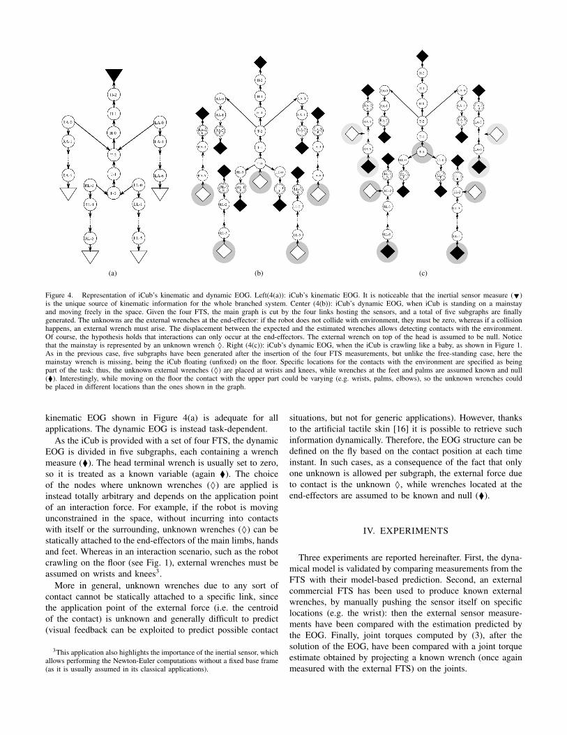
Figure 4. Representation of iCub’s kinematic and dynamic EOG. Left(4(a)): iCub’s kinematic EOG. It is noticeable that the inertial sensor measure (▼)is the unique source of kinematic information for the whole branched system. Center (4(b)): iCub’s dynamic EOG, when iCub is standing on a mainstayand moving freely in the space. Given the four FTS, the main graph is cut by the four links hosting the sensors, and a total of five subgraphs are finallygenerated. The unknowns are the external wrenches at the end-effector: if the robot does not collide with environment, they must be zero, whereas if a collisionhappens, an external wrench must arise. The displacement between the expected and the estimated wrenches allows detecting contacts with the environment.Of course, the hypothesis holds that interactions can only occur at the end-effectors. The external wrench on top of the head is assumed to be null. Noticethat the mainstay is represented by an unknown wrench ◊. Right (4(c)): iCub’s dynamic EOG, when the iCub is crawling like a baby, as shown in Figure 1.As in the previous case, five subgraphs have been generated after the insertion of the four FTS measurements, but unlike the free-standing case, here themainstay wrench is missing, being the iCub floating (unfixed) on the floor. Specific locations for the contacts with the environment are specified as beingpart of the task: thus, the unknown external wrenches (◊) are placed at wrists and knees, while wrenches at the feet and palms are assumed known and null(⧫). Interestingly, while moving on the floor the contact with the upper part could be varying (e.g. wrists, palms, elbows), so the unknown wrenches couldbe placed in different locations than the ones shown in the graph.
kinematic EOG shown in Figure 4(a) is adequate for allapplications. The dynamic EOG is instead task-dependent.
As the iCub is provided with a set of four FTS, the dynamicEOG is divided in five subgraphs, each containing a wrenchmeasure (⧫). The head terminal wrench is usually set to zero,so it is treated as a known variable (again ⧫). The choiceof the nodes where unknown wrenches (◊) are applied isinstead totally arbitrary and depends on the application pointof an interaction force. For example, if the robot is movingunconstrained in the space, without incurring into contactswith itself or the surrounding, unknown wrenches (◊) can bestatically attached to the end-effectors of the main limbs, handsand feet. Whereas in an interaction scenario, such as the robotcrawling on the floor (see Fig. 1), external wrenches must beassumed on wrists and knees3.
More in general, unknown wrenches due to any sort ofcontact cannot be statically attached to a specific link, sincethe application point of the external force (i.e. the centroidof the contact) is unknown and generally difficult to predict(visual feedback can be exploited to predict possible contact
3This application also highlights the importance of the inertial sensor, whichallows performing the Newton-Euler computations without a fixed base frame(as it is usually assumed in its classical applications).
situations, but not for generic applications). However, thanksto the artificial tactile skin [16] it is possible to retrieve suchinformation dynamically. Therefore, the EOG structure can bedefined on the fly based on the contact position at each timeinstant. In such cases, as a consequence of the fact that onlyone unknown is allowed per subgraph, the external force dueto contact is the unknown ◊, while wrenches located at theend-effectors are assumed to be known and null (⧫).
IV. EXPERIMENTS
Three experiments are reported hereinafter. First, the dyna-mical model is validated by comparing measurements from theFTS with their model-based prediction. Second, an externalcommercial FTS has been used to produce known externalwrenches, by manually pushing the sensor itself on specificlocations (e.g. the wrist): then the external sensor measure-ments have been compared with the estimation predicted bythe EOG. Finally, joint torques computed by (3), after thesolution of the EOG, have been compared with a joint torqueestimate obtained by projecting a known wrench (once againmeasured with the external FTS) on the joints.
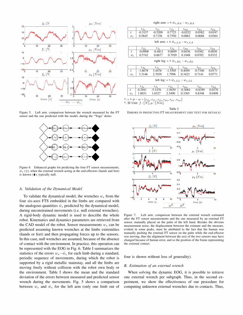
Figure 5. Left arm: comparison between the wrench measured by the FTsensor and the one predicted with the model, during the “Yoga” demo.
Figure 6. Enhanced graphs for predicting the four FT sensor measurements,ws (◊), when the external wrench acting at the end-effectors (hands and feet)is known (⧫), typically null.
A. Validation of the Dynamical Model
To validate the dynamical model, the wrenches ws from thefour six-axes FTS embedded in the limbs are compared withthe analogous quantities ws predicted by the dynamical model,during unconstrained movements (i.e. null external wrenches).A rigid-body dynamic model is used to describe the wholerobot. Kinematics and dynamics parameters are retrieved fromthe CAD model of the robot. Sensor measurements ws can bepredicted assuming known wrenches at the limbs extremities(hands or feet) and then propagating forces up to the sensors.In this case, null wrenches are assumed, because of the absenceof contact with the environment. In practice, this operation canbe represented with the EOG in Fig. 6. Table I summarizes thestatistics of the errors ws−ws for each limb during a standard,periodic sequence of movements, during which the robot issupported by a rigid metallic mainstay, and all the limbs aremoving freely without collision with the robot own body orthe environment. Table I shows the mean and the standarddeviation of the errors between measured and predicted sensorwrench during the movements. Fig. 5 shows a comparisonbetween ws and ws for the left arm (only one limb out of
right arm: ε ≜ ws,RA −ws,RA
εf0 εf1 εf2 εµ0 εµ1 εµ2
ε -0.3157 -0.5209 0.7723 -0.0252 0.0582 0.0197σε 0.5845 0.7156 0.7550 0.0882 0.0688 0.0364
left arm: ε ≜ ws,LA −ws,LA
εf0 εf1 εf2 εµ0 εµ1 εµ2
ε -0.0908 -0.4811 0.8699 0.0436 0.0382 0.0030σε 0.5742 0.6677 0.7920 0.1048 0.0702 0.0332
right leg: ε ≜ ws,RL −ws,RL
εf0 εf1 εf2 εµ0 εµ1 εµ2
ε -1.6678 3.4476 -1.5505 0.4050 -0.7340 0.0171σε 3.3146 2.7039 1.7996 0.3423 0.7141 0.0771
left leg: ε ≜ ws,LL −ws,LL
εf0 εf1 εf2 εµ0 εµ1 εµ2
ε 0.2941 -5.1476 -1.9459 -0.3084 -0.8399 0.0270σε 1.8031 1.8327 2.3490 0.3365 0.8348 0.0498
*: ε ≜ w −w = [εf0 , εf1 , εf2 , εµ0 , εµ1 , εµ2 ]
*: SI Unit: f ∶ [N], µ ∶ [Nm].
Table IERRORS IN PREDICTING FT MEASUREMENT (SEE TEXT FOR DETAILS)
Figure 7. Left arm: comparison between the external wrench estimatedafter the FT sensor measurements and the one measured by an external FTsensor, manually placed on the palm of the left hand. Besides the obviousmeasurement noise, the displacement between the estimate and the measure,evident in some peaks, must be attributed to the fact that the human wasmanually pushing the external FT sensor on the palm while the end-effectorwas moving, thus the alignment between the axis of the two sensors may havechanged because of human error, and so the position of the frame representingthe external contact.
four is shown without loss of generality).
B. Estimation of an external wrench
When solving the dynamic EOG, it is possible to retrieveone external wrench per subgraph. Thus, in the second ex-periment, we show the effectiveness of our procedure forcomputing unknown external wrenches due to contacts. Thus,
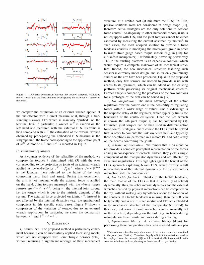
Figure 8. Left arm: comparison between the torques computed exploitingthe FT sensor and the ones obtained by projecting the external FT sensor onthe joints.
we compare the estimation of an external wrench applied atthe end-effector with a direct measure of it, through a free-standing six-axes FTS which is manually “pushed” on theterminal link. In particular, a wrench wE is exerted on theleft hand and measured with the external FTS. Its value isthen compared with wE , the estimation of the external wrenchobtained by propagating the embedded FTS measure in thesubgraph until the frame corresponding to the application pointof wE . A plot of wE and wE is reported in Fig. 7.
C. Estimation of torques
As a counter evidence of the reliability of the method, wecompare the torques τ , determined with (3) with the onescorresponding to the projection on joints of an external wrenchapplied at the end-effector τE = J⊺Ew
E , where JE ∈ R6×n
is the Jacobian (here referred to the frame of the nodeconnecting torso, head and arms). During this experiment,the arm is not moving, while the external force is appliedon the hand. Joint torques measured with the virtual torquesensors are τ = τ I + τE , being τ I the internal joint torque,i.e. the torque which is due to the intrinsic dynamic of thesystem. The external force projected on joints, τE , instead isnot affected by the internal dynamics (e.g. the gravitationalcomponent in this specific static case). Figure 8 shows acomparison of the variation of torque, due to an externalwrench application. In particular, we show the comparisonbetween τE and τE = τ − τ I .
V. DISCUSSION
1) Virtual JTS: The proposed method is particularly conve-nient because it can be successfully applied to existing robots,which are not equipped with Joint Torque Sensors (JTS),without requiring a significant redesign of their mechanical
structure, at a limited cost (at minimum the FTS). In iCub,passive solutions were not considered at design stage [21],therefore active strategies are the only solutions to achieveforce control. Analogously to other humanoid robots, iCub isnot equipped with JTS, and the joint torques cannot be eitherestimated by measuring the current absorbed by motors4. Insuch cases, the most adopted solution to provide a forcefeedback consists in modifying the motor/joint group in orderto insert strain-gauge based torque sensors (e.g. in [10], fora Stanford manipulator). Unfortunately, providing pervasivelyJTS in the existing platform is an expensive solution, whichwould require a complete makeover of its mechanical struc-ture. Indeed, the new mechanical structure featuring suchsensors is currently under design, and so far only preliminarystudies on the arm have been presented [13]. With the proposedmethod, only few sensors are needed to provide iCub withaccess to its dynamics, which can be added on the existingplatform while preserving its original mechanical structure.Further analysis comparing the pros/cons of the two solutionsfor a prototype of the arm can be found in [17].
2) On computation: The main advantage of the activeregulation over the passive one is the possibility of regulatingforces within a wider range of values. One disadvantage isthe response delay of the regulator, which typically limits thebandwidth of the controlled system. Once the i-th wrenchis known, the i-th joint torque τi can be computed by (3).Estimated joint torques can be then used in different activeforce control strategies, but of course the EOG must be solvedfirst in order to compute the link wrenches first, and typicallythese operations are performed in a remote PC and not directlyon the boards controlling the joints.
3) A better representation: We remark that JTSs alone donot provide a complete perceptual representation of the forcesarising in consequence of contacts. Indeed, they yield a singlecomponent of the manipulator dynamics and are affected bystructural singularities. This highlights again the benefit of theEOG approach exploiting 6 axis FTS, which provide a fullrepresentation of the internal dynamics of the system and itsinteraction with the environment.
4) On tactile feedback: Thanks to the tactile feedback,the main feature of the EOG is that it is built (and solved)dynamically: thus, the robot internal dynamics and the externalwrenches caused by physical interactions can be computed onthe fly, without making any hypotheses about the location ofthe contacts. If a tactile feedback is missing, than the EOG canbe typically built a priori, since inertial and FTS are embeddedin the mechanical structure of the manipulator (i.e. fixed). Inthis case, unknown external wrenches can be manually setin the structure, depending on the task: e.g. in hands duringmanipulation tasks, wrists and knees during crawling.
5) Open-source library: A software library (iDyn) forperforming these computations has been released with an open
4This solution is feasible only when most of the motor torque is transmittedto the joint (low friction). Therefore, highly efficient transmissions need tobe employed (see for example [9]) which is intrinsically incompatible withcompact solutions such as planetary or harmonic drive gear trains.
source license [1], and included in the iCub software.6) Applications: The effectiveness of the algorithm has
been proved in several experiments with the iCub: in fact,the computation of the so called “virtual joint torques” bymeans of the iDyn library enabled different forms of activeforce control, ranging from torque to impedance control, not tomention the possibility to detect external forces, thus allowinga compliant interaction with the environment and the humanscooperating with the robot. Numerous videos of realized ap-plications can be found at http://www.youtube.com/robotcub.
VI. CONCLUSIONS AND FUTURE WORKS
We presented a method for exploiting measurements frommultiple sensors distributed on an open (multiple branches)kinematic chain, which provides a complete representation ofthe dynamics of a robot. The theoretical framework presentedin this paper can take into account information coming fromdifferent sets of sensors, such as force/torque, inertial, tactile.A graphical representation of the sensory information of therobot, called EOG, combined with standard dynamics algo-rithms allows propagating wrench measures and computingboth joints torques and external wrenches due to contacts,applied at known locations. It was also shown that given N -FT sensors, a maximum of N + 1 external wrenches can beestimated. In the future, we plan to integrate the numerousadditional sensors (inertial measures from the boards, JTSfrom the main joints in the limbs [17]) in order to have amore accurate representation of the dynamics of the robot,particularly by means of sensor fusion algorithms. Moreover,having more measurements would notably improve the esti-mation of the dynamic parameters of the rigid-body dynamicsmodel of the robot.
REFERENCES
[1] Doxygen documentation of the iDyn library. http://eris.liralab.it/iCub/main/dox/html/group iDyn.html.
[2] E. Colgate and N. Hogan. The Interaction of Robots withPassive Environments: Application to Force FeedbackControl. Advanced Robotics. Springer-Verlag, 1989.
[3] R.S. Dahiya, G. Metta, M. Valle, and G. Sandini. Tactilesensing from humans to humanoids. IEEE Trans. onRobotics, 26:1–20.
[4] O. Eiberger, S. Haddadin, M. Weis, A. Albu-Schaffer,and G. Hirzinger. On joint design with intrinsic variablecompliance: derivation of the DLR QA-joint. In IEEEInt. Conf. Rob. Autom., 2010.
[5] R. Featherstone. Exploiting sparsity in operational-spacedynamics. Int. Journ. Robotics Research, 2010.
[6] R. Featherstone and D.E. Orin. Dynamics. In SpringerHandbook of Robotics, pages 35–65. 2008.
[7] M. Fumagalli, M. Randazzo, F. Nori, L. Natale, G. Metta,and G. Sandini. Exploiting proximal F/T measurementsfor the iCub active compliance. In IEEE/RSJ Int. Conf.on Intelligent Robots and Systems, 2010. Taipei, Taiwan.
[8] S. Haddadin, A. Albu-Schaffer, A. De Luca, andG. Hirzinger. Collision detection and reaction: A con-
tribution to safe physical human-robot interaction. InIEEE/RSJ Int. Conf. Intell. Robots and Systems, 2008.
[9] Barret Technology Inc. The WAM arm from barret tech-nology. http://www.barrett.com/robot/products-arm.htm.
[10] J.Y.S. Luh, W.D. Fisher, and R.P.C. Paul. Joint torquecontrol by a direct feedback for industrial robots. IEEETrans. on Automatic Control, 28(2):153–161, 1983.
[11] G. Morel and S. Dubowsky. The precise control ofmanipulators with joint friction: A base force/torquesensor method. In IEEE Int. Conf. on Robotics andAutomation, pages 360–365, 1996.
[12] G. Morel, K. Iagnemma, and S. Dubowsky. The precisecontrol of manipulators with high joint friction using baseforce/torque sensing. Automatica, 36(7):931–941, 2000.
[13] A. Parmiggiani, M. Randazzo, L. Natale, G. Metta, andG. Sandini. Joint torque sensing for the upper-body ofthe iCub humanoid robot. In IEEE-RAS Int. Conf. onHumanoid Robotics, France, 2009.
[14] U. Pattacini, F. Nori, L. Natale, G. Metta, and G. Sandini.An experimental evaluation of a novel minimum-jerkcartesian controller for humanoid robots. In IEEE/RSJInt. Conf. Intell. Robots Syst. Taiwan, 2010.
[15] G. Pratt and M. Williamson. Series elastic actuators. InIEEE/RSJ Int. Conf. Intell. Robots Syst., USA, 1995.
[16] A. Del Prete, S. Denei, L. Natale, F. Mastrogiovanni,F. Nori, G. Cannata, and G. Metta. Skin spatial calibra-tion using force/torque measurements. In IEEE/RSJ Int.Conf. Intell. Robots Sys., San Francisco, CA, USA, 2011.
[17] M. Randazzo, M. Fumagalli, F. Nori, L. Natale, G. Metta,and G. Sandini. A comparison between joint leveltorque sensing and proximal f/t sensor torque estimation:implementation on the icub. In IEEE/RSJ Int. Conf.Intell. Robots Sys., San Francisco, CA, USA, 2011.
[18] A. De Santis, B. Siciliano, A. De Luca, and A. Bicchi.An atlas of physical human-robot interaction. Mechanismand Machine Theory, 43(3):253–270, March 2008.
[19] L. Sciavicco and B. Siciliano. Modelling and Control ofRobot Manipulators. Springer, 2005.
[20] B. Siciliano and L. Villani. Robot Force Control. KluwerAcademic Publishers, Norwell, MA, USA, 2000.
[21] N.G. Tsagarakis, G. Metta, G. Sandini, D. Vernon,R. Beira, J. Santos-Victor, M.C. Carrazzo, F. Becchi, andD.G. Caldwell. iCub - the design and realization of anopen humanoid platform for cognitive and neuroscienceresearch. Int. Journal of Advanced Robotics, 21(10):1151–75, 2007.
[22] N.G. Tsagarakis, B. Vanderborght, M. Laffranchi, andD.G. Caldwell. The mechanical design of the new lowerbody for the child humanoid robot ’icub’. In IEEE/RSJInt. Conf. Intell. Robots Sys., St. Louis, MO, USA, 2009.
[23] J. Wittenburg. Topological description of articulatedsystems. Computer-Aided Analysis of Rigid and FlexibleMechanical Systems, pages 159–196, 1994.
[24] K. Yamane and Y. Nakamura. Parallel o(log n) algorithmfor dynamics simulation of humanoid robots. In IEEEInt. Conf. Humanoids Rob., 2006.