COMPUTERIZATION OF OPERATION AND MAINTENANCE FOR …
191
IAEA-IWG-NPPCI-94/6 LIMITED DISTRIBUTION WORKING MATERIAL COMPUTERIZATION OF OPERATION AND MAINTENANCE FOR NUCLEAR POWER PLANTS Fma! draft Report prepared within the frame, 'ork of the International Working Group om Nucisar Power Fiant Control and instrumentation Reproduced by the IAEA Vienna, Austria, 1994 NOTE The material in this iocument has been supplied by the authors and has not been edited by the IAEA. The views expressed remain ihe responsibility of the named authors end do not necessarily reflect those of the govcrnmcnt(s) of the designating Member Statc(s). In particular, neither the IAEA nor any other organization or body sponsoring this meeting can be held responsible for any material reproduced in this document.
Transcript of COMPUTERIZATION OF OPERATION AND MAINTENANCE FOR …

IAEA-IWG-NPPCI-94/6LIMITED DISTRIBUTION
WORKING MATERIAL
COMPUTERIZATIONOF OPERATION AND MAINTENANCE
FOR NUCLEAR POWER PLANTS
Fma! draft
Report prepared within the frame, 'ork ofthe International Working Group om Nucisar Power Fiant
Control and instrumentation
Reproduced by the IAEAVienna, Austria, 1994
NOTEThe material in this iocument has been supplied by the authors and has not been edited by theIAEA. The views expressed remain ihe responsibility of the named authors end do notnecessarily reflect those of the govcrnmcnt(s) of the designating Member Statc(s). In particular,neither the IAEA nor any other organization or body sponsoring this meeting can be heldresponsible for any material reproduced in this document.

FOREWORD
The need to use computers for nuclear power plant design, engineering, operation andmaintenance has been growing since the inception of commercial nuclear power electricity generationin the 1960s. The needs have intensified in recent years as the demands of safety and reliability aswell as economic competition have become stronger. As a result, IAEA member states have requestedassistance and advice to guide their use of computers in nuclear power plants.
The rapid advance of computer hardware and software technology in the last two decades hasgreatly enlarged the potentials of computer applications to all aspects of design and engineering offuture plants as well as operation and maintenance of existing plants. The traditional role ofcomputers for mathematical calculations and data manipulation has been expanded to enhance humanperformance and corpo^te business by information processing and knowledge-based systems.
This report provides a resource for computerization of activities in plant operation andmaintenance. Experience gained from design and implementation of various computer systems aroundthe world is described. The material may be useful as a guide to modification and upgrading ofexisting plants as well as design and engineering of new plants. It should be particularly of interestto managers and engineers who are engaged in planning, bidding, specifying or designing computersystems for operation and maintenance applications.
The technical document is the result of a series of advisory and consultant meetings held by theIAEA in Vienna in 1991 - 1994. The document was prepared with the participation of experts fromCanada, France, Germany, Hungary, Japan, Russia, Sweden, United Kingdom, and the United States.
Chapter 1 gives objectives and outlines the goals of the International Atomic Energy Agency insponsoring this report to promote cooperation in the use of good practice in computerization ofoperation and maintenance activities in nuclear power plants.
Chapter 2 is an overview. It covers the motivation for the application of computers, the currentpractice in use of computers, the advantages and disadvantages, human and machine interactionconsiderations and safety versus non-safety aspects of computer application.
Chapter 3 describes computer applications to the operation of nuclear power plants. It coversgeneral aspects of on-line, real-time applications for instrumentation, control and protection systems,as well as operator aids for diagnostics and decision making.
Chapter 4 depicts the aspects of computer use in maintenance of nuclear plants. It covers the useof a database to support various activities including maintenance administration, outage planning, workauthorization, tagging, spare parts management and computer-aided monitoring, inspection andsurveillance, etc , and their related design and implementation issues.
Chapter 5 covers life cycle management of computer systems, with focus on die user aspects ofdealing with changes, modifications, verification and validation, quality assurance and overallconfiguration management of the computer systems.
Chapter 6 outlines future trends and gives recommendations based on lessons learned from designand implementation, as well as R&D trends.
Chapter 7 provides a summary of the conclusions of this report.
Chapter 8 lists references for this document.
The Annex gives specific examples taken from direct experience of participating nations ofcomputer applications in the field.

Special thanks are due to Mr. Bill Sun of the Electric Power Research Institute of USA, whocompiled and edited the document from contributions provided by the working group members,particularly, Mr. A. Cook of Canada, Mr. D. Spohn of France, Mr. W. Bastl of Germany and Mr. D.Welbourne of UK. The other contributors are recognized in the section of "Contributors to Draftingand Review" in this report.
The officer of IAEA responsible for preparing this document is Mr. A. Kossilov of the NuclearPower Engineering Section.

CONTENTS
OBJECTIVE1.1. Operation and Maintenance of Nuclear Power Plants 91.2. Scope of the Report 91.3. Purpose of the Report 9
OVERVIEW OF COMPUTERIZATION ON NUCLEAR POWER PLANTS2.1. Use of Computers in Nuclear Power Plants 10
2.1.1. Historical Evolution 102.1.2. Reasons for Applying Computers 10
2.2. Overview of Application Areas 112.2.1. Computer Applications to Operations 11
2.2.2.2.2.2.2.2.2.2.
.1. Data Logging 12
.2. Information Systems and Operator Aids 12
.3. Monitoring and Diagnostic System 12
.4. Digital Control and Automation 131.5. Protection 14
2.2.2. Computer Applications to Maintenance 142.2.2.1. Predictive Maintenance and Inspection 142.2.2.2. Maintenance Management 14
2.2.3. Engineering and Administrative Functions IS2.3. Human-Machine Partnership 15
2.3.1. Functions Which Must be Automated by Computers 152.3.2. Functions Which are Better Automated by Computers 162.3.3. Functions Which Should be Allocated to Humans 162.3.4. Balancing "Factors 17
2.4. Relationship to Safety and Availability 182.4.1. System Considerations 182.4.2. Regulatory and Licensing Requirements 182.4.3. Computers for Safety Applications 18
2.4.3.1. Advantages 182.4.3.2. Challenges 19
COMPUTER APPLICATIONS TO OPERATION OF NUCLEAR POWER PLANTS
3.1. Introduction 213.2. Monitoring, Control and Protection Architecture 24
3.2.1. Monitoring Systems 243.2.1.1. Operator Information Systems for Plant Monitoring 243.2.1.2. Specialized Reactor Monitoring 24
3.2.2. Fault-Tolerant Control Systems 243.2.3. Integrated Control and Monitoring 27
3.2.3.1. Objectives 273.2.3.2. Safety and Availability 273.2.3.3. CONTROBLOC Layout in a 1,300 MW Nuclear Power Plant 29
3.2.4. Protection Systems 313.3. Information Systems and Operator Aids 31
3.3.1. Information Systems in the Control Room 313.3.1.1. Information Presentation Methodology 333.3.1.2. Experience with Video Display Unit Systems in Control Rooms 33
3.3.2. Operator Aids 363.3.2.1. Diagnosis and Prognosis 363.3.2.2. Experience 38
3.4. Control and Automation ; 393.4.1. Automatic Control Functions 393.4.2. Sequence and Interlock Control 40
h
3.4.3. Integrated Control and Multiplexing 413.5. Protection Systems 41
3.5.1. Introduction 413.5.2. Representative Systems 42
3.5.2.1. Integrated Digital Protection System 423.5.2.2. Integrated Protection System 453.5.2.3. The Inherently Safe Automation Trip System 46
3.5.3. Experience 46
4. COMPUTER APPLICATION TO MAINTENANCE OF NUCLEARPOWER PLANTS
4.1. Introduction 484.2. Maintenance Management 48
4.2.1. Basic Maintenance Files 484.2.2. Maintenance Administratior/Routines 504.2.3. Outage Planning 504.2.4. Materials Management 524.2.5. Maintenance Support Functions 524.2.6. Other Administrative Functions 52
4.3. Equipment Performance Applications 544.4. Advantages and Benefits 54
4.4.1. Quality 554.4.2. Production 554.4.3. Cost 55
5. MANAGEMENT OF COMPUTERIZED INFORMATION SYSTEM5.1. Management of Hardware, Software and Data 565.2. Change Control 565.3. Quality Assurance for Computer Systems 57
5.3.1. QA Requirements 575.3.2. Commercial Systems 575.3.3. Verification and Validation 575.3.4. Qualification of Software and Hardware 58
5.3.4.1. Hardware Qualification 585.3.4.2. Software Qualification 59
5.3.5. Documentation 605.4. Configuration Management and Change Control 60
5.4.1. Architecture Management and Change Control 605.4.1.1. Objectives 605.4.1.2. Architecture Constraints for Designers 605.4.1.3. Organization 61
5.4.2. Standards 615.4.2.1. Functional Standards 615.4.2.2. Communication Standards 615.4.2.3. Data Dictionary 625.4.2.4. Data Storage 62
5.5. Obsolescence and Retrofitting 625.6. Implementation Issues 63
5.6.1. Organization 635.6.2. Implementation of Databases 635.6.3. Training 635.6.4. Investments Required to Achieve Results 64
6. FUTURE TRENDS AND RECOMMENDATIONS
6.1. On-line and Off-line Data Management 64

6.2. Diagnosis and Prognosis Systems 646.3. Computer-Assisted Operating Procedures 656.4. Touch Screen Control 656.5. Distributed Systems 666.6. Equipment with Embedded Software 666.7. Communication Systems 666.8. Network Management 676.9. Standardization of Information Exchange 676.10. Data Architecture and Management for Maintenance 676.11. Effective Verification and Validation Methods 676.12. Configuration Management 686.13. Fault-T.Herant Design 69
7. CONCLUSIONS 69
8. REFERENCES 72
ANNEX: REPORTS ON THE USE OF COMPUTERS FOR NUCLEAR POWER PLANTOPERATIONS AND MAINTENANCE
Data Management as a Pre-requisite for Configuration ManagementA. Cook
The Contribution of an Information Management System to EdF Corporate StrategyD. Spohn
Advanced Computer-based Information Systems to Enhance Man-machineCommunication in the Control RoomW. Basti, L Felkel, D. Wach
Core Monitoring Systems for VVER 440 PWR'sF. Adorjan, L. Burger, I. Lux, M. Makai, J. Valko, J. Vegh, I Hamvas andZ. Kalya
Computer-based Operator Decision AidsY. Shinohara
Computer-based Support for Operation, Maintenance and ManagementA. Andersbon
CompuKr employ nent in protective action control systems for VPBER-600 nuclearpower plantA. B. Pobedonostsev
The Torness Advanced Gas-cooled Reactor Direct Digital Control and Data ProcessingComputer SystemsD. Welbourne
Enhanced Functions of Process Computer Systems for Nuclear Power PlantsB, Singer, S. BhattandB. K.-H. Sun
CONTRIBUTORS TO DRAFTING AND REVIEW
IAEA PUBLICATIONS ON NUCLEAR POWER PLANT CONTROL ANDINSTRUMEN : ATION
ABBREVIATIONS
ú

1. OBJECTIVE
1.1. OPERATION AND MAINTENANCE OF NUCLEAR POWER PLANTS
The advance of computer technology has been significant in recent years. The use of powerfulpersonal computers and workstations is widespread in all sectors of industry. The role of the computerin nuclear power technology includes design, engineering, operation and maintenance and has grownsteadily in the last decade. The use of computers has been extended from its traditional contributionof manipulations of large quantities of numerical data and mathematical equations for the design andengineering of nuclear power plants to its more current role of fast and accurate processing ofinformation and applying knowledge-based systems for operation and maintenance of capitalinvestment.
Operation and maintenance are fundamental aspects of a utility corporate business to keepnuclear power plants safe and reliable and to provide economic electric power. The major goals ofusing computers in operation and maintenance of nuclear power plants are (1) to improve safety andreduce challenges to capital investment; (2) to reduce the cost of operations and maintenance; (3) toenhance power production, and (4) to increase productivity of people.
The functions and tasks of operation and maintenance are closely related to each other.'Operational needs include areas of control and protection, and manual actions in a control room thatcall for continuing and periodic surveillance, testing and maintenance of equipment. The need ofmaintenance is to keep a plant in an optimal state for safe and economic operations.
In the past decade, there has been a growing need to address obsolescence, improve humanperformance, and to comply with increasingly stringent regulation requirements. As a result, nuclearpower plants have implemented plans to replace ageing analogue systems with digital systems andhave developed comprehensive and accessible information database and management systems. Thesesystems support operations and maintenance for an overall improvement in quality assurance andproductivity. The advances in information and communication technology have been proved to helputilities operate power plants more efficiently by integrating computer resources and increasing theavailability of information to meet NPP staff needs and corporate business strategy.
1.2. SCOPE OF THE REPORT
This dominent contains technical and methodological information and recommendationsrequested from member states for advice and assistance in the use of computers for operation andmaintenance, for backfitting of existing plants and for new power plants.
1.3. PURPOSE OF THE REPORT
The main purpose of this report is to provide information on practices and methodologies whichmay be used for computerization of operation and maintenance of NPPs, not only by the plantdesigners, but also by the utilities and the manufacturers of equipment and systems to meet operationaland safety requirements.
This document also provides information concerning different approaches to the use ofcomputers, tlu history of operational ex,-erience, lessons learned, and a summary of a existingcomputer systems.
The information is an overview and the reader is encouraged to seek additional detail in thereferenced documents related to the particular applications that are of interest.

The state-of-the-art and future trends in the use of computers in operations and maintenance,including cost benefits, man-machine interface, life-cycle management, verification and validation, etc.,are also considered in view of the fast evolution of the technology.
2. OVERVIEW OF COMPUTERIZATION ON NUCLEAR POWER PLANTS
2.1. USE OF COMPUTERS IN NUCLEAR POWER PLANTS
2.1.1. Historical evolution
In the 1970s, computer applications to operation gained broad recognition. The implementationof several large-scale, advanced control rooms and integrated control systems in the United States wereunfortunately terminated due to setbacks of nuclear plant orders in the time period. Nevertheless, theadvance of digital systems application in broad areas of operation and maintenance has beencontinuing around the world.
Digital technology has been increasingly recognized as a valuable tool for support andenhancement of human capability in the areas of monitoring, diagnosis, control, protection,maintenance, surveillance and communication.
2.1.2. Reasons for applying computers
Computers are applied to operation and maintenance for NPPs because they provide, but are notlimited to providing, the following main advantages: [1-1S]
- Complex protective and interlock functions, with extensive logic or calculations, often usingproven PLC units of higher reliability and lower cost than relay systems.
- Automatic control for plant conditions which could not otherwise be possible, givingimproved plant performance.
• Complex and rapid calculation facilities to allow on-line assessment of reactor conditions,giving improved safety, power output and economy.
• VDU to display of plant conditions, which can reduce control panel size and increaseoperational effectiveness.
• Automatic records not otherwise possible, which often have a safety role.
- Plant control with reduced cable requirements of cable quantity, size, number of terminationsetc, and thereby improved safety and economy.
- Use of proven systems for controlling inventory, purchasing, spares and management ofmaterial.
- Use ufccononi: methods of storing and manipulating large quantities of data, either on-lineor off-line to the process plant, and providing information to NPP staff.
The needs arise in the on-line, real-time processes of control and protection, alarm detection anddisplay, and in the on-line assessment of processes needed for operation of a power reactor. Inaddition, they arise equally in the semi on-line operation needed for daily or hourly assessment ofoperation; for example, monitoring of detailed reactor flux distribution. The need to use computersalso arises in the administration of the station to ensure safety, control of staff access and maintenanceof spares and inventory.
10

NPP designers found that they could gain operating advantages if a calculation could producesome output of a value or condition which cannot be directly measured. For example, the NPPdesigners want displays of in-core flux profiles, interpreted from ex-core measurements. They wantprotection functions based on maximum heat flux for PWRs. They require safe refuelling operationwhen fuel movement may involve complex configurations of fuel ponds, transfer paths, bottling units,etc., which need careful interlocking and control.
NPP designers found good reasons for designs with mechanical systems and boilers wherecomplex control algorithms must be followed to prevent metallurgical damage. The hazardrequirements may require fail-safe action to be taken by equipment in swhchgear rooms if cables aredestroyed by fire. Such operations are either very difficult or even impossible unless computers areused. Several international standards have been developed to guide the design of digital systems fornuclear plant applications. [19 • 22]
The penalty of using computers can be a high risk of short-term failure of achievement or evendelay in NPP delivery of power. A major problem can be the demonstration that computer systemsare satisfactory for safely, since the system may have a direct impact on protection or even provideprotection directly. Very high costs can be incurred in demonstrating the safety of a software systemand in verification and validation of the final system due to the complexity which was in itself thereason for using computers [23].
A major difficulty with the application of computers is that the requirements of a NPP arealways special and specific. Much on-iine software must, therefore, be specifically written and thehardware configuration is generally difficult to obtain off the shelf. A major problem withprocurement of on-line systems has been and continues to be the need for internal redundancy toensure high availability of the computer functions. These problems have often prevented the designintentions from being fully achieved, and the economic benefits expected have not always beenfulfilled in consequence.
NPP managers were quick to adopt commercially available database management systems, forthe control of spares and inventory, for staff access control and records, for management ofinformation, etc. Development has been rapid, and modem power stations are designed with a fullproject database of all items in the plant, all drawings in CAD format, and all project designdocuments held and controlled through computer systems. On the other hand, problems have beenfound in ensuring compatibility of information and its accuracy. The software systems for such totalinformation control are very extensive, and have been found to be difficult to produce in the allocatedtimescales, and difficult to fill with the vast amount of data accurately.
2.2. OVERVIEW OF APPLICATION AREAS
2.2.1. Computer applications to operário»
The use of computers on-site date back almost to the beginning of commercially applied nuclearpower. At this time a central computer served as a data logger. With the progress of technology,smaller dedicated computers have been introduced, which now serve for data acquisition, exchangeof data throughout the plant, information generation by means of simple logic or more complicatedanalytical functions, and by providing the desired information to the operator in die control room,usually by means of VDUs.
In parallel, computers began to be used for open and closed loop control and are also appliedfor the protection of the plant. Early protection applications often were limited to calculating safety-relevant parameters such as departure from nucleate boiling (DNB); later applications included allsignal handling, trip detection and redundant majority voting functions.
11

Theoretically, we can distinguish between computers used:
• for storage of operational data in order to have available historical data for later checkup orcomparison and
• for real-time data management in order to serve all needs of on-line monitoring andautomation.
2.2.1.1. Datalogging
The first major computer system used in nuclear power stations was the plant process computerwhich typically processes thousands of analogue and digital signals. These computers provide theplant operators with basic data to facilitate smooth startup and shutdown operations, as well asefficient, steady state operation. They generally provide alarms. The process computer has undergonecontinuous renovation and replacement as the old I960 computer systems have become obsolete. Insome modern plants, such systems are considered safety related.
2.2.1.2. Information systems
On-line computers are used in control rooms with two main goals • information presentation andinformation generation [5, 6, 8, 9, 12, 14].
High definition colour VDUs are normally used for information presentation. The informationcan be shown in the form of system diagrams with inserted parameter values and plant states, trendcurves showing the history of important physical parameters, and as listings of plant alarms in groupsor according to their priority. The information on one VDU screen will be a selected subset of allinformation, and therefore is serial rather than parallel in nature. It is therefore important to arrangesimple and direct methods of selection at other associated displays, for example, by pan and scrollfacilities to display adjacent plant groupings on the process, or by linked navigation facilities usingsoft keys, mouse or tracker ball facilities. Often, fixed keys give rapid selection of the most frequentlyused displays and alarm listings.
Some systems have reduced the difficulty of associating information from several displays atonce by grouping several VDU screens together in the control panels. One of the more successfulmethods is to group the method of selection of displays from an overview screen for a plant are» (e.g.the reactor primary coolant circuit, or the steam generators) with rapid selection of detailed displaysusing pre-programmed targets on the overview. By these means, rapid location of the alarms of aplant is possible, and the operate- s retain a spatial view of the plant through the relationship of thedisplays to the overviews
Information generation and concentration are basic to the use of computers. They are thereforeused with the VDU to present concentrated or calculated information, selected information andhistorical trend information. Information functions such as status monitoring, heat and mass flowvisualization, critical function monitoring, and success path monitoring can be included. Thesefunctions will select information and present it in flexible formats which are designed to includecalculations and dau selection processes, and present the necessary information for the operator useand support the decisions needed for each task for safety or for the next steps in a plant manoeuvre.
In the course of development, such functions have often been implemented as stand-alonesystems or operator aids, driven by operational needs of a specific plant or by licensing requirements.Typical examples are core power mapping systems, load following advisors and safely parameterdisplay systems. Today, these systems are normally integrated into the total station data processingand display system of euncnt pu^.-ss computers as well as in advanced control rooms.
2.2.1.3. Monitoring and diagnostic systems
12

Monitoring of the mechanical components and systems of the plant is an important applicationof computers. On-line monitoring and diagnostic systems have been applied to reactor vessel internals,pumps, safely and relief valves and turbine generator. The monitoring techniques include noiseanalysis, vibration analysis, and loose parts detection. Complicated signal analysis may be involved,e.g. conversion into the frequency domain, application of correlation and pattern recognition methods,etc. Comparison to reference values or "signature" information and trending are important tasks.More recently, expert system methods have been introduced in order to improve the performance ofsuch systems.
The advantages of performance, therefore, cause computers to be increasingly used to enhancemonitoring and diagnostic functions, to make the methods applied more user friendly and to achievethe necessary user acceptance.
Since a main goal of the diagnosis systems is the early detection of a developing mechanicaldeficiency, the importance for maintenance and inspection is obvious. Experience shows that due tofindings of the on-line diagnosis systems, the preparation of repair actions can be considerablyimproved, and maintenance and inspection times can be reduced.
2.2.1.4. Digital control and automation
As utilities in recent years have met problems of obsolescence of analogue technology andunavailability of spares, the existing analogue systems have been gradually replaced by digitalcontrollers. Fault-tolerant digital feedwater and reactor power and power distribution controllers havebeen successfully designed and implemented for advanced gas cooled reactors, CANDU plants, BWRsand PWRs [24-28].
The designs can provide dual redundancy with rapid bumpless changeover on failure of onechannel, bumpless transfer from manual to automatic control, signal validation of sensor inputs, asimple man-machine interface, and control algorithms able to handle wide ranges of plant conditionswith the non-linearity features needed for the wide range of plant dynamics. The operating experienceof these digital control systems has demonstrated that for some applications they improve operationalreliability and avoid reactor trips and outages, their main advantage is however simplification and costreduction of maintenance and better information and documentation about actual implementation.
2.2.1.5. Protection
The first application of the digital computer in a reactor protection system of a nuclear powerstation was the installation nf the Core Protection Calculator (CPC) in the Arkansas Nuclear One, Unit2 (ANO-2) plant in the late 1970s [29]. The intensive licensing review process proved to be achallenge to the utility. Extensive efforts, including review and testing, were made by the utility andits supplier to validate and verify the design and performance of the computer system. This effort,as well as the operating experience of the ANO-2 plant since 1979, has demonstrated that computerscan be used effectively for safety protection functions. The US NRC published a detailed assessmentof one such proposal [30].
A similar computerized version of a Local Core Protection system (using Cobalt incore detectorsignals!) was for years installed in the NPP Grafcnrheinfeld for studying purposes as a fourchannel/open-It nip arraiiginent [31-33].
Recently, nuclear plants have begun to implement digital protection systems for replacement ofobsolete analogue units. These digital systems include self-diagnostics and self checking featureswhich can substantially reduce testing and surveillance functions by operators. One full computerizedsafety shutdown system has been installed in the CANDU plant and digital protection systems havebeen operational in French 1300 MW PWRs. Neutron flux measurement systems with reactor trip
13

functions performed by computer equipment are installed in several Swedish BWR plants (Ringhalls,Forsmark and Barsebâck) and is being installed at present in the Kerncentrale Borssele in theNetherlands. Simipcnn N. Л computerised protection system (described in section 3.5.2.3) is installedat Dungeness В AGR in UK. Л computerized protection system has been installed for Sequoyah PWRin the USA and the Si/ewell В PWR in the UK. In the boiling water reactor Gundremntingen ssubsystem of a limitation system to protect ag?Jnst channel dry out is in operation [34]. The safetyimplications have been proven to be a major challenge to the applications of computers to protectionsystems [7. 16, 23].
2.2.2. Computer application to auiatnaacc
2.2.2.1. Predictive maintenance and inspection
The application of computer technology to maintenance and inspection has recently gainedincreasing attention. On- line monitoring and diagnostic systems have been applied to reactor vesselinternals, steam general, i -, pumps, safety and relief valves, and turbine generators. Digital processingof sensor information has been coupled with adaptive learning techniques for analysis, e.g. theneutron, acoustic, radiographie, nhrasonic, or eddy current signals, and provide a decision supportsystem for predictive maintenance.
Technical specification monitoring systems have been developed which enable plant maintenancepersonnel to achieve compliance with operational licensing requirements while maintaining flexibilitywith respect to maintenance schedules and system configuration.
Special computer equipment is also used for performing recurrent tests of the rather sophisticatedLimitation Systems (in semiconductor technique) in Geman PWR NPPs [35].
2.2.2.2. Maintenance management
As utilities implement more and more computer software and hardware, a need has emerged fora comprehensive and accessible information database and management system in nuclear plants. Thisinformation database supports maintenance, commitment tracking, personnel management, andradiological control, etc., for overall quality assurance and productivity enhancement. The advancesin computer communication technology have been proven to help utilities operate power plants moreefficiently by integrating computer resources and increasing the availability of information to meet theneeds of NPP staff.
The basic support systems in current use, or being developed, include the following:
- Daily work planning, including maintenance work plans, preventive maintenance program,daiíy work schedules for crews.
• Outage planning including compiling list of all work, resource analysis and preparation,critical path analysis, §;,' «duling and prioritization of work.
- Material management, including material specification, equipment spare pans lists, materialstorage and ordering systems.
• Maintenue support, including radiation hazard surveys, qualification requirements forspecialized work, calibration records, and management of specialized tools.
There is also a trend in the utility industry to apply knowledge-based expert systems to variousengineering, maintenance and operations functions. Expert systems technology has a number ofspecific capabilities which include: programming flexibility, inference capabilities, explanation facility
14

and knowledge structured according to human models. Expert systems can be used as an aid to helpachève £oals set by the electric power utilities. Examples of successful implementations are PWRviiîer chemistry diagnostics, reactor emergency action level classifications, emergency operatingprocedures tracking, diesel generator diagnostics, and fuel shuffle planning.
A recent advance in this area is the use of expert systems and neural networks in recognizinghand-drawn text and symbols on engineering drawings. Designed to save costs for power plants tomaintain design configurations and knowledge and to facilitate design modifications, the patternrecognition techniques convert the scanned binary raster image of a drawing into intelligent, computer-aided design (CAD) objects such as lines, arcs, circles, symbols and text. Development of the semi-automated drawing conversion tool will provide cost effective ways to extract information fromengineering diawings to populate-CAD and other plant databases.
2.2.3. Engineering and administrative functions
There are a number of engineering and administrative functions that are typically computerized.Examples of such systems include:
- Basic administrative systems for payroll, word processing, budgeting and accounting.
- Basic communication systems such as electronic mail and electronic bulletin boards.
- Fuel and physics systems to manage the insertion of new fuel bundles and storage ofirradiated fuel.
• Technical support systems such as computer-assisted drafting, reliability statistics analysis,and |>,:rforinaiice reporting systems.
- Safety analysis systems, such as are used for reactor physics modelling, thermal andhydraulic analysis, containment pressure analysis, risk analysis and registry of licensingdocuments.
2.3. HUMAN-MACHINE PARTNERSHIP
Many functions in NPPs are achieved by a combination of human actions and automation.Increasingly, computer-based systems are used to support operations and maintenance personnel in theperformance of their tasks. There are many benefits which can accrue from the use of computers butit is important to ensure that the design and implementation of the support system and the human taskplaces the human in the correct role in relation to the machine; that is, in an intellectually superiorposition, with the computer serving the human. In addition, consideration must be given to computersystem integriiv, soft\\;ii<. validation and verification, consequences of error, etc. To achieve a balancebetween computer and human actions, the design process must consider each operational function inregard to either computer, human operation, or more commonly, in nuclear plants a combination ofhuman and computer. The process is usually known in the ergonomics literature as "allocation offunctions" [17,19].
2.3.1. Functions which must be automated by computers
The first consideration must be to examine any function for which a computer is mandatory.It is desirable that any such task definition would be justifiably based on human factor principles, butthis may not always be so where mandatory requirements are based on established custom andpractice. The designer must identify all the functions which, by virtue of their nature and theirrequirements, can only be achieved using a computer. As a general statement, these can be definedas those which i \ceed the capabilities of human performance. In determining whether a function fallsinto this cate,. ..ry, the design team must consider the long-term demands of the task, the required
15

performance under the worst possible conditions, and the variability of the human operator.Performance factors which will need to be addressed include: required task rate, accuracy,repeatability and, in particular, the consequence of error. Functions which exceed the capacity orcapabilities of humans include:
- Processing large quantities of data
- Tasks requiring high accuracy
- Tasks requiring high repeatability
- Tasks requiring rapid performance
- Situations in which die consequences of error are severe
- Situations in which errors cannot readily be retrieved or corrected
Typical applications in a NPP for which the use of computers will be necessary include: datarecording, analysis and archive. Depending on the particular task performance requirements, in allsuch cases it will be easy to demonstrate that one or more human capabilities would be exceeded ifthe resulting task were performed manually.
When a decision is being taken to use computers for a function, consideration must be given tosupplementary tasks, such as maintenance and testing activities, which are required to allow thecomputer to perform its role [36]. It is important that the benefit of using computers is not lost byassigning supporting functions to human actions where the performance of the computer system wouldbe degraded owing to poor maintenance, or where human operators may have difficulties with copingwith the psychological impact of automation [37].
2.3.2. Functions which are better automated by compaten
Certain functions may be identified which, although lying within the capability of humanperformance, may be better assigned to a computer. These include those functions which are lengthy,require high consistency, high accuracy or involve a degree of risk to an operator. Tasks which wouldresult in boredom or monotony for an operator also fall into this category. The progressive increasein the capability of technology means that computer use can be considered for more and morefunctions. Th. cost of such technological solutions is often seen to be falling, and computer usebecomes an increasing possibility. The point at which computers are regarded by users as necessary,or become a normal expectation, changes as societal and workplace values change.
An additional benefit of using computers is the potential improvement which they can bring tothe design of jobs and working conditions by changing the role humans play in technology-basedsystems. With careful job design, significant improvements in operator roles can be achieved. Theremay also be consequential improvements in overall system performance.
Practical examples of computers being introduced to replace tedious or arduous human activitiesinclude the use of machines to carry out maintenance or surveillance activities; for example, steamgenerator examination. Computers are also being used increasingly to carry out lengthy, repetitivetesting such as that for safety and protection systems. Not only does this improve the role of theoperator, but it also brings improvements in the consistency of testing and may allow it to be carriedout more frequently.
2.3.3. Functions which should be allocated to huma»
Functions which require heuristic or inferential knowledge, flexibility, etc., will need to be
16

assigned to humans. In addition, there may be practical or technical constraints which make computersimpractical and thus require human operation. In many cases, it will be possible to justify assignmentof such functions to the human. However, there is a risk that functions will be so assigned simplybecause computers would be difficult to use or uneconomical in some way. Regrettably, a functionmay be assigned to a human simply because there is a lack of a precise specification or some difficultyin producing one. It may prove possible to produce a workable system in this way but there is a riskthat the result produced is an unsuitable or inappropriate set of tasks for the human.
A particular set of functions which is currently left with the human operator is that which occursin extreme fault or accident situations where human flexibility and high level skills are essential andthe unexpected nature of the task makes specifying appropriate computer functions difficult orimpossible.
2.3.4. Balancing factors
The following qualitative factors will govern the relative weighting used in allocating functionsbetween humans and computers.
1. Existing practices: The exient of using computers depends on operational practices and thelevel of technological and experiential support that is available. For example, staff trained incomputer maintenance may be required before a high degree of computer use is possible.
2. Operational and design experience: Experience is often critical in establishing the confidenceand justification for further use of computers. For example, if an organization has successfullyimplemented computer functions which have resulted in fewer spurious plant shutdowns, thatutility is more likely to consider using more computers.
3. Regulatory/actors: Regulating bodies establish specific rules which may restrict or, conversely,require the use of computers.
4. Feasibility: Sometimes using a computer is not possible for practical reasons. For example,installation downtime may preclude modification in an existing plant.
5. Cost: There are very few cases where other factors will totally outweigh costs. A cost benefitmust exist to justify most proposals to use computers.
6. Technical climate: Increasing capabilities of technology may facilitate the use of computerswhile unavailability of technology may limit what can be achieved by computers.
7. Policy matters: An organization may develop policies that encourage or discourage usingcomputers. For example, the decision to standardize on a type of plant design may determinethe level of computer use.
8. Cultural and social aspects: The modified role of the operator in a highly automated plant mayrepresent a social problem that can lead to loss of motivation and significantly decreasedperformance.
The various factors which exist may differ between applications and may be affected by whethera new design or a modification to an existing process through retrofit is being considered. In theretrofit case, the implementation of computers has less flexibility, owing to existing plant designs,operating practices, the need for replication, etc.
17
2.4. RELATIONSHIP TO SAFETY AND AVAILABILITY
2.4.1. System considerations
A computer system for operation and maintenance (O&M) of a power station will be installedbecause it improves safety, plant availability or economy of operation. The relationship of thecomputer to these factors must be carefully considered during system design. When a computer isintended in a NPP to improve safety, its impact on availability must be considered, and vice-versa.A specific factor which has been of importance is the need for internal redundancy of the computersystem to ensure continuity of operation of the functions during single failures of computer modules.Often, proprietary equipment able to provide comprehensive control and display facilities for processplants may be available only on a single channel basis, and this can make it unusable for a NPP bothon availability and safety grounds.
When an on-line computer system is intended in a NPP, its role in the maintenance or provisionof safety must be considered with care, as for any item of I&C. Its role in the safety of the stationshould be assessed usii.^ the criteria given in IEC1226 [38] and its basic reliability, redundancy,environmental durability, Quality Assurance (QA), and other requirements determined in accordancewith that document.
2.4.2. Regulatory and licensing requirements
Special care must be given to the requirements of licensing and regulatory bodies in regard tosoftware systems. Safety and protection systems can be considered as a special case of controlsystems. They have additional regulatory and technical requirements imposed on them [39-41].Requirements for good practice for such systems is given in IEC 880 - "Software for Computers inthe Safety Systems of NPP" [21], and a supplement under preparation by IEC/SC45A on recentdevelopments, increasing the scope of the recommendations to cover all computer systems importantto safety, as defined in f AEA-50-SG-D3 & D8 [42,43]. Additional requirements such as the use ofFormal Mathematical Methods in design, very comprehensive and independent V&V, testing on site,etc may also be applied to safety systems in some countries.
The duty of licensing and regulatory staff includes consideration of factors which may not havebeen thought of by the designers. It must, therefore, be always remembered that a computer systemmay be found to have a role in safety which had not been clearly foreseen, and, therefore, the bestpractice will be necessary in design, installation and operation even of computers which provide anoperating aid or support function.
2.4.3. Computers for safety applications
2.4.3.1. Advantages
Specific reasons for considering computers for applications important to safety include:
1. The ability to process large volumes of complex information rapidly.
2. The ability to process the data, and to display information rapidly to the operators.
3. The ability to present complex information in a form which can be easily interpreted.
4. The ability to validate the process information by automatic checks during the input process andby software which compares similar or related signals.
5. The ability to obey complex algorithms or calculations in determining the plant state and safety.
18
6. The possibility of saving space for equipment cabinets or cables in the station layout.
7. The minimization of electrical penetrations from reactor containment structures by the use ofmultiplexed signal transmission.
8. The provision of safety information from the safety system via separate routes both to a MainControl Room (MCR) and to emergency or support control points, such that all information canbe shown and recorded, and remains available if the MCR must be evacuated.
9. The retention of data on previous events, fault transients or trips (as a post-event record or areference "signature") for later analysis.
10. The ability of computer equipment to self-test and thereby to provide modules with fail-safecharacteristics.
2.4.3.2. Challenges
Challenges which have been encountered in applying software systems to applications importantto safety include:
1. The computer application may be thought to reduce operator "on-the-job" involvement.Management action for training and for ensuring job satisfaction will be needed.
2. The redundancy of the computer system must be considered carefully and the actual in-servicereliability of computer modules should be determined during design. Redundant, hot-standbysystems can achieve outage levels below 1 to 10 hours/year. This requires very careful design.
3. The use of a computer for a function important to safety must include consideration of commonmode failure of the computers. If a monitoring function is provided by two separate channelsof a computer system, consideration should be given, for example, to separate power sources,separate environmental control systems, and separate equipment rooms and cable routes.Furthermore, consideration must be given to the need for some form of backup and diversemethod of providing the function if the system does suffer a common mode failure of softwareor hardware.
4. Programmable devices are in themselves complex, and may be modified by the manufacturerwithout notification. Analysis to determine failure modes, and careful QA audit trails will beneeded for a safelv system application, although less stringent measures may be acceptable forless criiual funcli its.
5. The overall system design of a computer system important to safety should consider carefullythe division and partitioning of the system between safety critical and safety related sections,both for the hardware and the software and the data within the systems.
6. The division of the system should take into account the need to assemble the system on site ina structured and systematic manner, and to build up operator familiarization effectively.
7. The use of a computer system to functions important to safety will depend on and interact withthe reactor system characteristics. This will be found to affect the functional requirements inmany ways. Interaction can be expected from:
a) The internal characteristics of the reactor and its self-regulation and self-limitingchai'.'t icristics >., cr its \,'iole operating parameter range.
b) The equipment installed on the plant, and the plant itself, in regard to normal and failure
19
modes of self-actuating passive devices, active devices, the characteristics of pneumaticvalves and actuators, the operation of regulation systems, etc.
c) Special requirements for reactor manoeuvrability conditions.
8. The computer systems partitioning and internal intercommunication must be considered carefullyin relation to the transmission of faulty data, defective programs or incorrect control commandsand the like. The safety system itself is subject to requirements of electrical isolation fromother, nonsafety systems. It must also be subject to comparable and stringent isolation fromdata, program, commands and information which is not of the safety system.
9. The computer software will consist of program code modules and data, which specifies how thecode is to act. The identification of the data and of its inclusion in the software is oftendifficult, and often a cause of error. Great care must be exercised, and careful managementprocedures followed, when data is prepared or changed.
10. The complexity of a safety functional requirement may be a major reason for choosing acomputer implementation. The result is, therefore, certain to be complex and may involve largequantities of computer code and data which may take a long time to produce, install and test.The challenge is therefore to identify simple safety functions, and to develop code able toperform it without unnecessary complexity.
11. The use of computers for functions important to safety must include a careful assessment of thepotential impact of a software failure. No method exists to guarantee no software errors willremain after final installation. Therefore, if redundant safety plants are each controlled byseparate software systems which use the same software modules, all redundant safety plant itemscould fail to act due to a single software error. The station system design, therefore, requiresconsideration to ensure some complementary control or alternative safety plant can be claimedto maintain safety if such an event occurred.
12. The quantification ofthe reliability of software-based systems remains a difficult area. The levelof complexity and the maturity of development and checking practices of analogue basedsystems has allowed the assumption to be made that the reliability of the system can bequantified as the random failure rate ofthe hardware, provided accepted development practiceshave been rigorously followed. The current position is that software failure is dominated bydesign errors, not be random failures, and consequent^ the analogue route is not open. Thechallenge is to produce a means of quantifying design failures for the software implementationprocess or to develop the arguments for showing the current analogue practice of using randomfailure rates can be justified for computer-based systems.
13. The through-life maintenance of computer-based systems can pose problems of differing natureto those encountered for analogue systems, the most common of which is time scales. Analoguesystems are generally installed for periods of 20 to 30 years and because ofthe relatively stablemanner in which the technology evolves, maintenance only becomes a problem towards the endof life as component manufacture ceases and stocks run out. The threat to maintenance ofcomputer-based systems comes from two sources, first for control and display systems thesoftware life is short. The systems are usually built around some proprietary kernel and supportis only available for the most recent kernel. This can force very frequent upgrades, theseupgrades can in turn force the need for hardware upgrade as the later versions ofthe softwareseek to exploit the latest hardware almost annually and appear to have a shelf life of only a fewyears. Critical systems that avoid proprietary software including operating systems would appearto face less of a problem as once in service they generally remain unaltered. Here the threat isgenuine hardware obsolescence which may occur on a long time scale (about 10 years) butshorter than for analogue hardware. There can also be a threat arising from the developmentenvironment and hence the maintenance environment, which is usually software dependent,
20

becoming unmaintainable.
14. A particular requirement of* regulatory authorities is for very high confidence in the correctstatement of requirements, and in its successful, error free implementation. To meet this, specialanalysis and review may be icquired and this may be very costly and demanding. The challengeis to meet this in an economic, timely and efficient manner.
15. Safety-related systems will require internal checks to prevent control system demands, alarmsettings, etc. from being set to unacceptable values, but may permit some inward data andprogram flow. In all cases, stringent measures to prevent corruption from unauthorizedcommunication and spurious connections must be enforced by system design, managementprocedures, internal software checks and lockouts and other appropriate measures.
3. COMPUTER APPLICATIONS TO OPERATION OF NUCLEAR POWER PLANTS
3.1. INTRODUCTION
When discussing the use of computers in the operation of a NPP, a very broad scale of both thecomputing devices and the activities they are meant for must be considered [44-47]. The operationalactivities are closely related to maintenance as described in Chapter 4. A computerized function isconsidered as a part of the operation of a NPP if:
- It has an interaction with the operational personnel or is on-line to the plant instrumentationand control equipment;
- It is real time or quasi real time;
- It is directly related to the systems and to the processes cf the NPP.
The basic functions usually provided for a nuclear power plant by on-line computer systems areplant monitoring and recording, and the display of information and alarms.
On a typical reactor plant, between 3000 and 7000 analogue signals from instruments measuringtemperature, pressure, flow and other special parameters will exist. In addition, between 10,000 and20,000 state signals will be used. These state signals provide information on switchgear states, valvestates, and alarm states and may include the states of control room switches [1,3].
The main use of the computer system is to read in these signals at intervals, typically onesecond, and to form an internal data base representing the plant condition.
That internal database is then available for software to perform checks of analogue signals forhigh, low and other alarms, and checks of state signals for alarms. In the alarm check process, thecomputer system provides recorded time of detection on printed logs and on magnetic media for off-line analysis. VDUs allow the alarms to be displayed to the operators, with clear language titles, theinstrument or plant contact identity, and other information.
The internal database can be used to operate VDUs to show the current plant state. A typicalinstallation may have 200 to 500 display formats, which group signals and présent their values andstates with suitable titles for each plant item, or plant system. Special displays can be designedappropriate to specific operations, for example, attaining reactor criticality or controlled steam raisingoperations. A typical installation will allow the operator to select any display to any VDU in thecontrol room. The display wilt appear within 1 or 2 seconds with current plant conditions shown andrefreshed at regular intervals of 2 seconds or less. Normally, any of these displays can be printed torecord the conditions seen, and printed logs showing the current state are available [48].
21

The use of modern high definition, graphic and colour VDUs gives many possibilities fordisplays with mimic presentation of the plant, dynamic symbols to show valve open/closed states,coloured histogram presentation of level, etc. Great care must be taken in the design of these displaysto ensure consistency of style and representation of all plant information, and the design should allowfor comprehensive review of the displays, a strong human factors input, and the views of the operatingstaff [49]. The VDUs can show the output of calculations; for example, to derive reactor flux profiles,or to identify the highest and lowest core exit temperature.
By storing sections of the database at regular intervals, histories of signals can be produced.These can then be displayed on VDUs to show trends as graphs of chosen signals.
Generally, graphs of turbine-temperature, vibration and other conditions are of special value, asare graphs of feedwater a id steam conditions. This information is normally available as a special log,retained or printed out at a turbine trip for identification of any turbine problems. Great care is neededin design to limit this i,'formation to that which is truly needed, and to avoid excessive numbers ofrecords being produced.
The database available within the computer system which represents the plant condition allowsrecords and logs to be produced both as printed records, and magnetic records. Special care is neededin designing these logs, in making a distinction between a log of the current state, a log which givesa historical record of signals (for example, the values taken every 30 minutes for an eight-hour shift),and a log which includes calculations such as average over time or integration of values such as leakrates over time. The logs provided on a station typically include shift handover information logs, dailyefficiency logs, routine logs at intervals of one hour or one day, and various post-trip logs fordiagnosis of reactor and turbine problems. A log of special importance is that which records theinputs, conditions, and actions of the reactor protection system so that the reasons for any trip maybe determined. The use of off-line VDUs can allow rapid inspection and checks of logs made inmagnetic form.
Typical computer functions are listed in Table I. This table shows a great variety ofcomputerized functions exists in various NPPs. This chapter discusses these functions according tothe following classification:
- Information and operator aid systems
- Computerized control and automation
- Computerized protection systems
It is worth mentioning, however, that the separation and order of the subject, as above, reflectsthe level of computerization of the activity at hand. Thus, while some sort of information and operatoraid computer system exist at almost every NPP, the application of computers to closed loop controlis more recent and the application to the protection system has been done only to very recent plantsand current designs of light water and CANDU reactor plants [50]. Particularly for the protectionsystems, safety implications and regulatory concerns have been major challenges to implementation[2,16,23,41].
When discussing the interaction with computerized services in a NPP, the intégration of thedistributed information and control systems through networking is a major concern. On the otherhand, distributed systems are usually involved in data acquisition and control and are connected andintegrated with other systems in higher hierarchical positions. In other words, the distributed unitsperform the primary, "in-field" task, the integrated system, like an envelope, covers the interconnectionbetween the various processes, possibly including also maintenance and design analysis.
22

TABLE I. TYPICAL COMPUTER FUNCTIONS
Basic FunctionsProcess CommunicationsHuman - computer communicationSequence of event recorderTransient recordingAlarm annunciationPersistent alarm handlingData loggingPostmortem reviewLimit checkingCommunication with in-core fuel management computer systemSelf checking
General FunctionsIssuing of production reportMeasurement of operation timeTransient recordingSupervision of safety functionsSupervision of plant statusSafety system testingRedundant input validity checking and mean value calculationsAutomatic surveillance testing
t
Core Supervision FunctionsNeutron flux calculation and displayNeutron flux sensor supervisionCore performance calculation and presentationIn-core neutron flux sensor calibration
Reactor Supervision FunctionsCalculation of reactor thermal powerPresentation of operating pointReactor coolant water quality monitoringCalculation and r rveillana of reactor vessel heating
Automatic Control FunctionsControl of startup fluxControl rod manoeuvre (fine motion control)Control of feedwater flowControl of reactor temperature and pressureBoiler or steam generator level controlControl of feedwater pumps
Protection FunctionsReactor trip detectionReactor trip actuationActuation of emergency safeguard systems
Turbine Governor and Supervision FunctionsMain-turbine supen ision asd governor controlTurbine condenser performance monitoring
23

3.2. MONITORING, CONTROL AND PROTECTION ARCHITECTURE
3.2.1. Monitoring systems
3.2.1.1. Operator information systems for plant monitoring
Modern monitoring systems depend on the operation of full colour VDU's, with full graphicfacilities [12,19,48,52]. The process plant information is held as a real-time database which can beaccessed by all VDU stations. The typical architecture includes full redundancy of all data transferpaths, multiple VDU work stations, and redundant gateways from data gathering networks orspecialized data sources such as the protection system. Redundant backing disc storage is included,together with redundant central processors for system coordination and database management. Theoperation of the processors will be on a hot-standby basis. A representative configuration is in Figure1. Such systems require large, special project teams to coordinate the design and implementation inall its aspects. Extensive use of off-the-shelf hardware will be needed for interfaces with othersystems, operation of hot-standby computers and other factors. A major technical point is therequirement for a high bandwidth on the interconnecting LAN or highway. Although extensivestandard system software may be available for such systems, they often require some system softwaredevelopment, and will require application software development which may be extensive.
The preparation, verification and validation of the data for each processing operation, eachsignal, and all VDUs and records is a very extensive task which is special to the particular NPP. Datamay be required for about 6000 analogue signals, 20,000 digital signals and 500 VDU de-signs, andthe magnitude of this task requires detailed and careful management.
3.2.1.2. Specialized reactor monitoring
For individual monitoring systems retrofitted in existing plants, the network architecture is muchsimpler than the plant-wide operator information system, as presented in the last section. Theseindividual operator aid monitoring systems are implemented, often in a modular and piecemeal fashion,for specific requirements and needs which are often driven by regulations.
Representative monitoring systems for reactors consist of redundant minicomputers withproprietary or specially designed interfaces to signal measurement and input digitization equipment.Redundant backing disc stores may be provided, and output will be to dedicated VDUs and printers.The systems may be able to provide very high availability even without redundancy. Such systemscan, today, be configured from off-the-shelf items with special-to-project software operating undercontrol of a proprietary operating system. A representative architecture is given in Figure 2.
3.2.2. Fault-tolerant control systems
Modern control systems typically have dedicated minicomputers or microcomputers, with aprogram for the automatic control functions and the operation of the input/output equipmentpermanently in Read-Only-Memory (ROM), or other permanent memory. Standard input digitizationcards and contact signal input sensing cards will be operated by the microprocessor. Standard digital-to-analogue converter units or other interface modules will be used.
To maintain availability, the minicomputers will be redundant, and they will both have fullaccess to all inputs and outputs. An arbitration unit will be used to assign which computer is on-lineand which is on standby.
Normally, the control system will send information on its actions to the monitoring computersystem. In early systems the control functions and monitoring functions were often in a singlecomputer system.
24

Main Processors and Disc StoresHot-Standby
Data fromreactorprotectionsystem
Gateways
DatacollectionLANs
-Plants i g n a l s .
Directplantsignals -
M
M
Multiplexers
Automatic controlsystem signals
В Local arca network
- \
l/f
vou
— vou
Workstations
-Mainn и паи i l l
convoi
room
vou
Output
CVP
CVP
Printersand
records
iWortcsiatiotVDUl-АшШагу
Vf. —Technical
VDU support
TosMjtennianeQeifieicomputers
Gateways
Figure 1. Representative Configuration of an Operator information Systemfor Plant Monitoring.

Redundant
Backing discstore
Dedicatedmonitor
Dedicatedprinters,recorders
plant signals »
A
В
Disc
VDU
Output
Inputscan
Inputscan
Inter*data h
ceighway
Input
VDU
Main control it
2 control•menace
Dedicated
Figure 2. Reprwenttrtiv* Architecture for a RMctor Monitoring Syttetn,

Such systems normally are implemented using a proprietary control language, giving the controlengineer direct access to operations for proportional, integral and derivative action, for hysteresis andfor actuator monitoring. It may be possible to configure the control design using an interactive CADapproach. Special software to interface with other systems may be needed, and for on-line/standbyoperation. A representative configuration is shown in Figure 3.
3.2.3. Integrated coitrol and Moaitoriag
A representative system which integrates control and monitoring is the CONTROBLOC system,installed on the EdF 1,300 MW nuclear power plants in France. The system receives control roomcontrols and information from tensors and actuators, performs the control logic and interlock functions,and operates station equipment and electrical switchgear accordingly. The system provides closed loopcontrol as well as information display on VDUs.
3.2.3.1. Objectives
The system objective is to provide high reliability control and plant signal monitoring, whilereducing the physical size of the control equipment by using microprocessor technology. To achievethis in a satisfactory way, it is necessary to select some specific targets. The selection of thesepreferred targets must take into account the field of application of the electronic system.
For example, an extensive hardware redundancy will increase availability, but will decreasereliability. Similarly, performing a frequent and detailed hardware integrity diagnosis, especially onthe passive components, gives the risN; of too tight overlapping of the action and survey loops, and oftoo frequent program interrupts. This will prejudice safe operation. Consequently, priority has beengiven to the four following design objectives:
• Safety and availability of automatic controls
- Adaptability to subsequent changes of process operation. Capability of performing newcontrol functions without changing the system architecture. CONTROBLOC is designed tobe a versatile system.
- Staff not acquainted with electronics and data processing techniques shall be able toconfigure, program, test, maintain, repair and modify the CONTROBLOC cabinets.
3.2.3.2. Safety and ens Ability
A high safety level means design for a risk of spurious or unsafe actuation commands which is"as low as practicable." Consequently, arrangements have been provided in the implementation andthe operation of the system including:
- Continuous checking of the validity of the data to be processed;
• Use of "2 scanning cycle" check procedures for the process data acquisition and transmiti ionof orders or information;
• Issue of actuation commands is prevented if a fault is detected within CONTROBLOC.
Galvanic isolation jf the inputs and outputs is another important feature of CONTROBLOCsafety. The inputs and outputs of a CONTROBLOC cabinet behave as effective barriers between theelectronic modules which use low level signals and the hostile plant environment.
The requirements for adaptability for subsequent developments of process operation and thecapability of performing new control functions are easily satisfied on account of the use of EPROM
27

LocDoperatorinterface
Redundant computer»
ллмпиюпmodule
Input
Input
input»
Plantinputs
Outputonw
- • Adwiorouipute
Hcdundantnliiftaoa dala
highway
ExlvrneJ systofTi
Flguf» 3. A napraiantaMvB Configuration of a fauH-totefant Control Sytttm.

memories which store user programs. The many microprocessors which are used in theCONTROBLOC have the capacity to perform the wiJe range of logic and analogue calculations whichwould be necessary if plant automation were increased.
The implementation or modification of a system by staff unskilled in electronics and dataprocessing techniques is a very stringent design requirement. The need to allow hardwareconfiguration to be defined by unskilled personnel has caused the CONTROBLOC system designersto organize it around a structure (cabinets, racks, power supplies, etc.) able to receive functionalmodules mounted on printed circuit boards. CONTROBLOC has a high modularity. Each logicmodule has a specific function and is operated by a dedicated program. Consequently all internalconnections of a cabinet are systematically made the same during design and hardwired on printedcircuit boards.
In order to program the EPROM memories easily, a CAD system is used to create the electricaldiagrams. These diagrams are automatically translated into logical equations and, after verification,are transferred onto EPROM's.
Application programs can be modified, and during modifications, a CONTROBLOC cabinetcontinues running. Due to the internal redundancy of the electronic unit, it is possible to separate theunit to be modified to carry out the program modifications and to test the modifications on the cabinetitself.
3.2.3.3. CONTROBLOC layout in a 1,300 Ж Nuclear Power Plant
A 1,300 MW PWR nuclear power unit has about 1,000 remote controlled actuators, 2000 logicand position sensors, 600acontrol devices, 3,000 alarms, 600 analogue signals and has to deal withalmost 6,000 Jata items '*"> be transmitted to the unit computer. Figure 4 shows a schematic layoutof the CONTROBLOC' lunction.
80 to 100 CONTROBLOC cabinets are required to process the relevant data. These cabinetscome from three families:
1. Automation cabinets
These cabinets receive logic data from the plant or the control room; they generate orders foractuators and alarms for the main control room and the unit computer. All actuators controlledby these CONTROBLOC cabinets are operated and supervised from a main, centralized controlroom, except those located in the nuclear auxiliary building (for the first 1,300 MW unit) andin the démineraiized water control station, which are operated locally and supervised from themain control room.
2. Common data cabinet
Some data concerning either status conditions of the nuclear plant or controls (e.g.,acknowledgement of alarm horn or alarm lights) must be distributed to a large number ofautomation cabinets. This data is acquired or processed by three cabinets designated "commondata cabinets" and transmitted through multiplexed links to all automation cabinets, which allreceive the same data three times. The receiving cabinets then process this dato in two out ofthree modes. Triple transmission of common data has been retained to allow the system totolerate the loss of a cabinet or a multiplexed link.
3. Alarm management units
The alam.s requesting immediate operator action are indicated by lamps connected, wire bywire, it. M-c autoiiiiition cabinets while others are displayed on VDU displays.
29

Selection
оü
Sequentialcontrol
Individualcontrol
Statusindication
Alarmdisplay
оО
CONTROBLOC
Indicationalarms
commandsmultiplexedexchanges
Multiplexedlinks
Controbloc
Alarmprocessing
Other links
Computer multiplexed links
Terminalbox
Controlpanels
Solenoid-valve
uncoupling
I
Sensor Solenoid-vaive
Motor
Motor actuated valve
Figure 4. A schematic layout of the CONTROBLOC function in French1300MWePWRs

The switching of alarms generated by a given automation cabinet to a given VDU is performedby a set of two CONTROBLOC cabinets, one devoted to the train A alarms, the second one devotedto train B.
Seven polychrome VDUs are mounted in the main control room; six display all alarms includedin the plant. The seventh VDU, used only as an alternative, displays alarms of safety В train systems.
3.2.4. Protection systems
The protection applications of computers is evolving, and no representative architecture canreadily be identified. Some generic features can be identified as follows: [23,24,52,53].
1. Protection of the reactor requires redundancy, and generally, a two-out-of-four approach isneeded.
2. Dedicated input systems, separated into four channels (for a 2/4 system), are required.
3. The highest industrial quality hardware is needed.
4. The application of fail-to-safe design principles is often required in individual nations.
5. Self-testing on-line is normally included.
6. Automatic off-line testers for all basic functions are normally included, with appropriatesafeguards on operation.
7. Specialized software is required, held in ROM or similar permanent memory.
A representative three-channel configuration is shown in Figure 5.
3.3, INFORMATION SYSTEMS AND OPERATOR AIDS
3.3.1. Information systems in the control room
The design and technology of NPP control rooms have been developed on the basis of the richexperience with the control rooms in conventional power stations [13,19].
Considering recent NPPs, VDUs are commonly used in the control room for monitoring datain conjunction with the conventional panels [51,54]. This may be characterized as a hybridinformation system where the operators are using the traditional and the new information tools as well[55]. In reality, the solutions arise from using VDUs as additional information sources as comparedto fully integrated designs where the plant must be shut down if the VDUs fail. Alternatively, astrictly limited set of independent instruments and alarms may be provided, sufficient only to allowa safe shutdown operation if all VDUs and computer services fail for longer than a defined period,typically of a few minutes.
Process computers have been used for a long time in order to provide monitoring andsurveillance of the plants, e.g. to print important alarms and disturbance messages or to providevarious types of calculations such as flux distribution or core power. With the advances in computertechnology on the one hand, and with the new information requirements (as described above) on theother hand, today integral concepts are more and more introduced, which try to meet informationneeds of operating, maintaining and managing of the plant as well.
31

Channel 1
Flux, temperature,pressure, flow, etc.
llll
Signal tripdetection
Digitization
Memory
Trip detectMicroprocessor
Memory
Electricalisolation & datacommunication
23
Voting
IData
transfer
Datareceiver
IMemory
Two out of threevote
microprocessor
Outputdrive
TTrip relay 1
Physical barriers
Channel 2
Voting
^Flux, temperature,pressure, flow, etc.
III!Digitization
Memory
Trip detectMicroprocessor
Memory
1Data
transfer
Datareceiver
IMemory
Two out of threevote
microprocessor
Outputdrive
T
Voting
Trip relay 2
Channel 3
Flux, tempera»; re,pressure, flew, ate.
U l lDigitization
Memory
Trip detectMicroprocessor
Memory
1Data
transfer
Datareceiver
•1•2
Memory
Two out of threevote
microprocessor
Outputdrive
Trip relay 3
Control rodpower -
supplies
Trip relay contacts or trip swHchgear contacts
Control rodoperation
Figure 5. A Representative configuration for a Three-channel Trip System.

3.3.1.1. Information presentation methodology
In early applications, only one or two VDUs, together with other instruments and alarms, wereused. The VDU can relate directly to the working controls. If it fails, the conventional instrumentcan generally lie used. However, the VOU must be operated on a page-by-page basis.
Recent approaches apply grouped VDUs and this offers several advantages: [56]
1. A single process can be simultaneously displayed in a number of different ways. This makesthe information more accessible, thereby facilitating understanding of the actions of complexI&C systems.
2. This multiple-screen presentation of the same function increases the fault tolerance of overallinformation output as, on the basis of experience, it is relatively easy to identify single failureswithin the information as a whole. This allows the capability of the human brain to identify anycontradiction.
3. The most important information can be moved to the centre. Information to be observed onlysporadically can be positioned at "parking spots" around this central information. A "quasi-window technique" allows overview formats to be displayed at the same time as detailedsubformats. The large size of the displays permits multi-person viewing at the same time.
4. Those visual display units which are not used in undisturbed operating conditions, canautomatically display menus of suggested formats as pointers to "off-design behaviour" in theevent of sudden disturbances.
A whole range of different features can be provided to allow rapid and easy access to the entirerange of stored information. These include single formats as well as direct selection of sets of formatsand direct access to neighbouring information and to hierarchical, extra information via the formatsthemselves. Of particular importance is a large range of possible types of presentations, and well-designed controls for selecting information.
Experience shows that there is a limited number of fundamentally important formats ("keyformats") which are required in most situations. Such single formats form a part of or supplement tothe multi-screen format sets and give the required information a particular transparent form. To ensurethat the displays are designed effectively, the design team should include direct representation of theultimate operating staff and also should directly include designers with human factors and ergonomieexperience [51].
3.3.1.2. Experience with VDU systems in control rooms
When discussing the VDU information technique, it is important to note that they do not simplyreplace conventional means but rather enable new ways for basic improvement of plant monitoring.In general, there are two types of presentations:
- System overviews with a hierarchical structure leading the user to more and more detailedinformation down to the component level.
- Task/function oriented displays which provide comprehensive information about the statusand dynamic behaviour of the processes to be observed, e.g. by means of diagrams.
Both types of presentations open up a new dimension of information. The first one enablesrapid and easy access to information when tracing back a problem through the system involved. Thesecond one provides a closer contact between the operator and the overall plant behaviour and providesa more direct contact with the processes (e.g. control actions and their influence on the process) which
33
could not be achieved by the former information means. More recently it is supplemented by adisplay presenting advice on how to cope with a faulty situation.
Operators must be able to track operation of the plant, and likewise, all situation and eventsequences for plant faults so that they are always completely informed of all processes involved. Thisenables them to take manual actions, where appropriate, for areas where this is admissible and tosupplement the automatic counter measures. Shift supervisors and specialists require additional,widespread and varied information.
In case of system operation with safety relevance, the operator has to rely on the informationprovided on the VDU. In some countries, information must be shown with colour to enhance clarity,and with a symbol or other indication that a change has taken place in the state or value of a plantsignal. This is done both to provide indications with safe properties, and also to ensure colour visionimpairment is not challenged. Where information is presented which is derived from redundantsensors, it is normal nuclear plant practice to provide VDU screens with all values arranged together,to allow comparisons ti. be made, and also to provide screens which show only the averaged value,with dynamic rejection of faulty signals using an appropriate validation algorithm. Where redundantcontact sensors are provided, algorithms have been used, and are being developed, which will detectdiscrepancy between the states and, where appropriate, will prevent unsafe action then being demandedby the operator. An appropriate algorithm is described in reference 85.
There are certainly various stages concerning the application of VDU systems in the controlroom. At present, VDU information is often used in addition to traditional information. Althoughthis seems to be a natural first step, very often there are complaints with respect to even moreinformation overload for the operator.
First experiences in Germany have been reported by the utility BAG [57]. The most importantoutcomes are given below.
(1) Automation
The degree of automation is ultimately determined by the safety requirements, operational needs,and the natural limits of human capability. From the point of view of human factors engineering andsystems ergonomics, concerns are often expressed with respect to decoupling of the operators fromthe process. The experiences reported show the opposite:
The additional VDU information system provides an essential means for fully understandingcomplex process situations; it forms the basis for integrating the operator into the world ofprocess automation.
The extensive process automation represents a considerable amount of the I&C knowledgecomplex. This knowledge has to be trained and adapted and comprises more than 50% of theoperators' teaching and training experience.
(2) Parallel and serial Information presentation
Traditional control rooms provide a good overview because of parallel stationary presentationareas of distinct information type. This may be lost by the window-type of information presentationas given by VDUs. The findings have been:
The VDU system showed the ability to replace the overview function mentioned above to alarge extent by means of overview pictures;
Since VDUs have been grouped into units (e.g. six VDUs in two levels on the console, for eachof the turbine and the reactor operator) disadvantages of serial presentation are highly
34

compensated. Several windows to the process are available at the same time. The mentalrequirement for picture and diagram selection was relatively low due to hierarchical structuresand menu selection.
(3) Plausibility checking
Plausibility checking of highly-condensed information is often considered a major problem whenusing new information systems. It is assumed that this may lead to decision lags:
According to the reported experience, plausibility control with the VDU system provides manymore possibilities than with the traditional system. It is believed that the high potential ofplausibility control is far firm being exhausted.
Future systems can be extended to even wider plausibility control by comparing measuredsignals with values calculated by on-line computation (analytical redundancy). It isrecommended that the design should provide measured values instead of calculated as a primeinformation source for the operator. When grouping or calculating information, care must betaken to ensure that the algorithms operate satisfactorily if a signal is defective or a scannersubunit is out of action.
(4) Participation of the operators in design and training
The participation of the operators in designing the information presentation is essential for lateracceptance. Training means for the new VDU system have to be provided:
Operators have Ы ,a integrated into the design process at an early stage. Even afia- putting thesystem into operai .MI, the team consisting of engineers from the vendor and the utility remainedworking.
This team still formulates improvements and new requirements. A trend to ask for even moreinformation about automatic action and their influence on the process can be observed.
The expectation with respect to the operators' acceptance of the VDU system has been fulfilled.
Training of the operators must consider the new information system.
A specific simulator (called a function trainer) is used in order to provide operators' training inaddition to the ou-site training.
(5) Verification and validation
Although the VDU system is used as an additive system, major V&V actions had to beperformed within the licensing procedure. This was due to the fact that safety-relevant informationis also given by the VDUs.
Since national NPP standards for this subject are not yet available, a guideline has to bedeveloped based on present national and international experience.
In the past, application of validation to existing systems has led to considerable additionalexpense and licensing delays. Software V&V procedures should be considered carefully, anddetermined so far as practicable, in the beginning of planning.
Soflwai. costs p osent a i : . ^ and n .>re dominant percentage of the total system costs of thefirst unit: more i!' ..i 70% ! as been attributed to software in some cases, with rising tendency.
35

Hence, the portability of software is an essential requirement of the utilities, especiallyconsidering the short innovation time of hardware. During the life time of the NPP, thehardware will need to be changed several times.
(6) Hybrid information system
In order to facilitate introduction of the new VDUs, the intermediate step of a hybrid solutionhas been adopted in some countries (i.e. the VDUs additive to a complete conventional control room),with three main points in mind — to ease adoption by the operators, to learn lessons and to gainexperience without impacting production and to better overcome licensing problems. Experienceshowed:
- The hybrid solution did not lead to undue operator load.
- The design solution found provides an optimal combination of traditional and advancedinformation systems.
- V&V and licensing can be gradually developed from operational systems to safety systems(e.g. SPDS).
3.3.2. Operator aidf
In regard to operator aids, it is common practice for information features to be introduced asadditional sources to those already available in the control room [14]. They date back to the TMI-2accident, where serious information deficiencies were observed, as a consequence of which the ideaof symptom-oriented procedures came up. These procedures were meant to be as simple as possibleand clearly directed towards a few definite safety goals, which have to be met in case of accidentsituations (e.g. adequate cooling of the reactor core, primary circuit integrity). The informationsystem to comply with this procedure was the SPDS (Safety Parameter Display System) [5,6,8,58].Its purpose was to indicate deviation of the defined Safety Parameters and to provide the subsets ofimportant measurement values in order to assist the operator in reaching the safety goals [59,60]. Theworld-wide impact of the TMI-2 accident has resulted in the widespread adoption of similar SPDSfunctions in other countries. The installation of computers and colorgraphic workstations is matchedby the development of sophisticated application software modules, such as signal validation softwareto be used as a preprocessor for the SPDS and emergency procedure monitoring, to integrate the rale-based control functions with the SPDS.
From then on, further development has been driven mainly by two factors: the desire to provideadditional help to the operator which goes beyond pure information; and second, the experience thatoperator aids which are practically never used for accident situations creates training and acceptanceproblems. Concerning the first factor, additional features like success path monitoring or statusmonitoring of safety- relevant equipment have been provided. The second factor caused extension intothe normal operation regime; consequently, the operator aid system was used in the normal workingenvironment and acceptance was achieved. Further, once this important problem had been solved, itwas no longer necessary to switch from one information means to die other dependent on theoperational regime [9].
Besides this main line of development, special aids have been developed and successfully usedfor operating purposes only. Among them are advisors for load following control, secondaryfeedwater control during part load operation, or assessment of Xenon poison and reactivity margins[45,46].
3.3.2.1. Diagnosis and prognosis
The enhancement of man-machine interface by means of VDUs accompanied by new forms of
36

information presentation is just one step. With the rising power of process computer technology, thetool was there to produce on-line high level information and to improve and condense information atthe same time. Among the new features, diagnosis and prognosis play an increasingly important role.This is because knowing about plant deficiencies at an early stage provides the maximum time foradequate measures. Corresponding to the operational needs, two main areas can be distinguished:
- aids to diagnosis arising during abnormal deviations of the plant process and for prognosisof the further development of these deviations;
- aids to diagnosis of the onset of mechanical deficiencies and for prognosis of furtherdevelopment of these deficiencies.
(1) Processes
The origin of process diagnosis and prognosis dates back to disturbance analysis systems whichhave been investigated and developed since the 1970s. The basic idea of these systems was to assistthe operator [61,62]:
- in tracing back a disturbance of the plant (which as a rule is indicated by alarm messagesaccompanied by a bulk of analogue readings) to its origin, the cause of the disturbance;
- by providing information about potential developments of the disturbance; and
- by providing recommendations for adequate countermeasures.
AH these developments were considerably hindered by access problems to the sensor signals,poor dynamics of digitized values (available via the plant process computer) and last but not least, bythe effort needed for system and process analysis. Yet, successful working of prototypes could bedemonstrated, partly in on-line experiments [63], Subsequently, these systems were further developedand led to integral concepts within the framework of advanced I&C and enhanced control rooms.
Today, the main goal of those systems has switched to diagnose a process in terms of initialdeviations from the normal state, i.e. to inform the operator about a developing disturbance beforereaching the traditional alarm levels. This calls for intensive analysis of die dynamic process andsystems behaviour so that the temporal development of the measured variables and their mutualinterrelation can be reliably interpreted. Possible presentation to the operator can be achieved, e.g.by a transient diagram [64]. This diagram shows the distance between actual process variables andthe defined limit values as well as denoting the time available until a limit value is reached in thecourse of transients. In the specific case, the graphical representation has been developed to monitortransients regarding the three ways of heat transport on the secondary side of a PWR(turbine/condenser, steam generator, relief/safety valves). For this purpose, distances and timeresiduals are computed and ordered for those process variables that have some effect on the currentheat transfer path once they have crossed a threshold and are approaching the trip level. This givesthe operator information about competing or mutually influencing factors of a jeopardy regarding therespective heat transfer paths. Twenty relevant variables have been selected. Beginning with theactual value (fixed marker line), the transient is mapped 30 minutes into the past and an extrapolationof IS minutes into the future is performed.
Enhanced diagnosis abilities are available now in various new information concepts, e.g. in theadvanced control room designs in France, Japan, and Germany [49]. Experience is young, butoperators adopt the new information possibilities and, after the adaptation phase, recognize die advancein information and prefer the new system as compared to the old one.
37

(2) Mechanical systems and components
Similar to the systems discussed above, a lot of development work had been done to providediagnosis and prognosis features for the mechanical health of the plant. In the past there was little orno direct information on this for the operator. Rather, he had to draw his own conclusions from theprocess behaviour supplemented by just a few sensors indicating the status of active components (e.g.turbine vibration). Since the 70s, more detailed investigations have been performed in France,Germany, and USA on diagnosis for loose parts vibration of reactor vessel internals and leakage inthe primary circuit. Indirect measuring methods and subsequent diagnostics techniques have beendeveloped based upon acoustic, vibration and process signal noise analysis [65].
Typical of the methods applied is the use of stochastic signal information. Therefore,considerable effort had to be placed on signal analysis and interpretation as compared to the usualreactor instrumentation. Depending on the problem, either analysis in the time or frequency domainis applied. Very often essential information is drawn from the interrelation between different signals(correlation analysis, pattern analysis). Especially for successful application of vibration diagnosis,extensive knowledge of the vibrational behaviour of the observed mechanical systems is necessary.Therefore, adequate рге-operation jl vibration tests which may require additional sensors and theoreticalmodel studies had to be performed. Also, databanks storing relevant events are necessary in order toallow for comparison.
Meanwhile, loose parts monitoring systems are installed in nearly all light water reactors [66].Regular vibration and leak detection analysis are applied to most of the PWRs. Loose parts in thereactor vessel or steam generator can cause structure damage, especially when they remain undetectedfor a longer time. Excessive mechanical vibration fatigue effects may cause breaks or loosening ofscrewed connections. The detection of these deficiencies is important from the operation and safetypoint of view.
3.3.2.2. Experience
As indicated above, operator aids provide special information or guidance to the operators.Typically they are realized as stand alone systems, or where sufficient on-line computer power isavailable, the additional information features are integrated in existing control rooms [67]. In recentdesigns, which are based on flexible, distributed, computerized I&C, these aids have been considerablyextended and, from the beginning, integrated in the overall information concept [4]. Design aspectsof these integrated systems are:
- task-oriented information, if feasible automatically following the actual plant situation;
- transparency of information, i.e. the operator receives full information on how and why theinformation systems derived its conclusions; and
- assurance of information validity and consistency, e.g. by on-line signal validation.
The experience with the operator aids used up to now are positive. They have achieved theirmain task, i.e. to save time in understanding complex situations and processes and to act in time. Asa result, human error has been reduced. Flexibility for adaptation to task extension and upgrading isobvious. Problems still exist with integration in the overall information system and with verificationand validation (V&V), not only due to computer hardware and software reliability, but also due toV&V of the underlying information condensation, which tends to become more and more complex.
Good experience has been gained with diagnosis systems for mechanical components in manycountries operating nuclear power plants. Among important findings are excessive core barrelvibrations due to relaxation of the clamping conditions, loosening of the secondary core support in thereactor vessel, loosened internals in the steam generator, etc. Loose parts monitoring has been
38

successfully applied in French and German plants. There is no doubt the systems have paid off [68].
In spite of successful operation, further development is necessary. One of the most importantproblems which still exists is the operation and use of the systems on site. Typically, measurementresults are stored and investigated by specialists in analysis centres. This certainly leads to decouplingof the operating staff from the systems and often results in acceptance problems. The future tendencyis to perform more analysis work in an automated manner on site and to generate condensedinformation which is easier understood by the staff.
One example pointing in this direction is a German condition monitoring system called COMOS[44]. It is used for on-line vibration analysis, and allows automatic simultaneous monitoring of upto 32 signals. In the spectra of each signal, up to ten frequency bands with adjustable band width canbe determined. Margins are let individually around learned reference states. The trends of thedifferent features are displayed gr phically. They can easily be followed by the operators; set pointscan be introduced and used in the control room for triggering an alarm.
As a consequence of this ou-site analysis feature, COMOS can also be used to monitor possiblefast escalating deficiencies, e.g., when using it for pump shaft vibration monitoring. This is describedin the annex.
By means of a new information correlation matrix, rules for vibrational relations in varioussignals and frequency bands can be programmed to realize diagnosis and prognosis properties. Stepby step the comprehensive and still growing knowledge-base can be implemented in the on-linemonitoring, so that in the future a diagnosis and prognosis system for vibration and anomalymonitoring will be available. The system is installed in 7 German PWR's with a successful operationexperience of 20 reactor years.
This is just one example of how even complex systems can be successfully applied on site.With the new powerful I&C systems now available on site, which typically have available aconsiderable computation capacity, similar developments in other diagnosis and prognosis applicationswill become available in the future.
3.4. CONTROL AND AUTOMATION
3.4.1. Automatic control functions
Analogue control modules were used on early nuclear power plants. However, they are nownot generally available due to commercial obsolescence. Since the early 1970s, the availability ofcomputer modules able to be configured for a three-element (proportional-integral-derivative) controlhas allowed their use for the simpler control functions not related to safety.
This use has grown, and more complex, non-linear control functions have been progressivelyincluded in nuclear power stations. A wide range of standard firmware modules are now availablefor such applications. Computers have been used for Distributed Digital Control (DDC) with greatsuccess in some countries since the 1970s. The advantages of using DDCs are flexibility of controlstrategy and it allows integration of control parameter schedules, giving wide control ranges. Theextensive non-linearities of behaviour of the plant can be covered in this way, for example, the transferfrom startup feedwater control to the main feedwater control mode at я power of about 10% [69,70].
An advantage of computers for gas cooled reactors has been the ability to provide DDC for theseparate automatic control of up to 40 control rods used for control of channel gas outlet temperatures.A typical application is described in detail in the Annex for the United Kingdom Advanced Gas-Cooled Reactor at Torness. The control functions needed to maintain station conditions of coolanttemperature, steam generator level, feedwater flow etc., are recognized as having a role in safety since
39

they maintain the reference conditions used by all safety analysis studies. They may have trip functionin control of heat removal. The use of computers for such control functions, therefore, may involvejustification of their performance as suitable for a safety-related function.
An interesting and important development in the application of computers is the operation ofactuators controlled by the station control functions. The control of turbine power on a modern plantwill involve the use of a microprocessor turbine governor controller whose setting is altered by thestation power control loop. The operation of control rods for recent PWR designs involves amicroprocessor controlled rod movement and sequencing system. Control of reactor coolanttemperature, therefore, involves transmitting demands to this control rod microprocessor system.
3.4.2. Sequence and interlock control
A successful application of computer control on most modem nuclear plants has been theautomatic run-up of the turbine, its synchronization and its initial block loading. This is normally asystem provided by the turbine manufacturer and its use is necessary to ensure satisfactory operationof the turbine for all temperature conditions.
Turbine run-up control has a wider character than a pure sequence since closed loop speed andacceleration control is used within the run-up sequence.
Control of refuelling is a standard application, in which a computer or a Programmable LogicController (PLC) is used to position the fuelling machine, operate its hoist and grab, and move the fuelto its fuel pond storage location. On some fuelling systems control applications, interlocks to preventmoving the fuelling machine during its operation, to prevent movement to specific locations, and toensure the fuel assembly is submersed, are required. This can be implemented through PLCs;however, great care is needed. If a potential activity release could be caused by a PLC malfunction,a detailed safety justification of the computer may be needed.
The use of computers to assist operators by automation of startup of nuclear plants is lesswidespread than for other classes of power generation, since nuclear plants are generally operated forbase-load generation over long periods. However, often the closed loop controllers are designed withschedules to allow automation of aspects of startup over a wide range.
On two advanced gas-cooled reactors built in the 1970's in the UK (Hartlepool and Heysham1), a complete automatic startup system has been integrated with the station automatic controlfunctions. On these stations, startup from below critical to about 30% power is normally undercomputer control, followed by full transfer to DDC of the station power and reactor conditions. Thestartup brings the reactui from zero power to criticality, then increases temperature and power, controlsthe boiling in the once-through boilers, and initiates turbine runup and loading, in several phases. Thesystem is used as a matter of routine on all startups.
For automatic control, the configuration of the computer system to ensure availability isimportant. Dual computer units, with automatic changeover, were used on earlier stations with DDC.All control functions were generally integrated in one mini-computer system. Modern micro-computers systems have distributed the functions, with a dual micro-computer subsystem for eachcontrol loop [70]. The computer system typically includes a Local Area Network (LAN), or a set ofdirect data links, to take messages from the control computer to the display and alarm computer. TheLAN will normally require redundancy, to ensure high availability, and this will allow a full checkof all messages sent.
Interlocks on the operation of plants may be needed to ensure, for example, correct valvepositions and lubrication vhen a pump is started, to prevent high pressure fluid entering low pressurepipework, or to prevent udioacthe fluid contaminating clean fluid. Such operations have normallybeen done by conventional wiring of limit switches and position switches in the control switchgear,
40

or by the use of equivalent solid state logic. PLCs or computers programmed with standard logicfunctions can achieve these interlock functions, and this application of computer equipment isincreasing. A wide range of industrial PLCs suitable for these functions is commercially available.
3.4.3. Integrated control and multiplexing
An application of computers which is becoming increasingly important is the multiplexing ofcontrol room controls. A computer system controls a Local Area Network (LAN), to which areconnected input/output multiplexing units which read control room switches, and operate plantactuators and switchgear. The multiplexing equipment can be physically distributed. Cubicles in thecontrol room area communicate control demands by optic fibre or coaxial cables to cubicles in theelectrical switchgear rooms or at plants [71,72].
The advantages of this approach are that:
(1) very extensive cable savings are possible;
(2) safety can be improved, since the potential for incorrect action caused by a cable fire can beeliminated; and
(3) total electrical isolation of plants from the control room is possible by use of optic fibres
If a control multiplexing system also monitors plant signals, and is used to provide infonnationto the alarm and display system, the displays can include full information on control switch states.A further advantage is that automatic records can be made directly from the actions taken in thecontrol room for analysis after an incident.
The computers used for such multiplexing normally are internally redundant, with a redundantLAN system. The very high possible availability allows the same network of multiplexers andcomputers to be used for automatic control and interlocks, giving integrated data collection andautomation. To allow for the fire separation needed on a nuclear station, two or more separatemultiplexing systems are needed, with the equipment and LAN cables of the two systems separatedand electrically isolated from each other.
An important extension of the use of multiplexing is the use of touch-screen control. In thisapproach, VDU screens are selected by the operators. These screens show control areas. Touchingspecific areas of the screen will activate 'open', 'close' or 'start', 'stop' actions, with confirmation ofthe selection by touching a further area of the screen.
If a multiplexing system is used for control, it is important to assess its significance to safety.If safeguard plants are controlled which are also operated by the reactor protection system, themultiplexing equipment may form part of the safety system and the special factors concerned, whichare discussed in Section 3.5, must be considered. It is also important to consider carefully duringdesign, the separation of control and data which is important to safety from other controls and data.Software and hardware isolation is needed to a suitable extent such that corruption of safety systemcontrol or data cannot take place.
3.5. PROTECTION SYSTEMS
3.5.1. Introduction
Reactor protection and safety actuation systems have been developed on the basis of analoguemodules to detect unsafe conditions, and logic modules to vote on those conditions [73]. Many earlysystems depended on industrial trip amplifiers and relays to perform voting on a one-out-of-two, two-
41

out-of-three, or two-out-of-four basis.
The need to demonstrate safety resulted in the use of high quality special designs of analogueand logic modules. The high availability required and the need for reduction of spurious trips has ledto a general present day requirement for two-out-of-four, and in special cases, three-out-of-four voting.Solid state equipment is standard, and some countries require equipment which has been designed tobe fail-safe.
To allow the highest possible reliability to be claimed, some countries have included a methodof diverse automatic shutdown, using relays or some alternative equipment, in addition to a solid stateprotection and safety actuation system.
The increasing complexity of the protection requirements has resulted in several nationsconsidering the use of software-based protection systems. These have generally been based on the useof standard microprocessors and computer input/output cards.
The confidence needed before a designer or utility has been prepared to consider computers forprotection has only been possible because of the successful experience of computers for data displayand control applications. In spite of this, major problems remain in the application of computers forsafety functions.
3.5.2. Representative systems
In spite of obvious advantages when using computerized protection systems (e.g. calculationof more complex parameters, adaptation to plant changes), the required reliability level and V&Vproblems have caused considerable delays in applications. Today, fully developed systems are inoperation on some PWRs, CANDU and other reactors. In the following, examples of digital protectionsystems are briefly described.
3.5.2.1. Integrated digital protection system
The Integrated Digital Protection System (SPIN) for 1300 M We nuclear power plants is intendedto produce an emergency shutdown of the reactor on detection of critical parameters outside normaloperating limits and to initiate suitable safeguard actions in the event of an incident or accidentsituation.
SPIN receives electrical signals (analog, logic or digital) representing the boiler quantitiesmonitored (physical parameters, neutron flux parameters, position of control rods, etc.) and outputscontrol signals to emergency shutdown circuit breakers and safeguard actuators. It comprises fourredundant Acquisition and Processing Units for Protection (UATP) and two redundant Safeguard LogicUnits (ULS) to which an automatic tester is added for periodic tests, as shown in Figure 6.
1) Acquisition and processing unit for protection (UATP)
The UATP, as shown in Figure 7, performs all the processing required to generate the protectionfunction tripping commands, i.e.:
• Acquires the sensor outputs,
- Processes these signals,
- Compares the computation results with the reference levels to obtain tripping information perparameter,
- Exchanges this tripping information between the UATPs,
42

2'3'4"
I Sensors {
II Instrumentation |
£UATPI
E
Manualcontrol
n
[ - • 2 3—•»•+ - • 3 4 - *L-*-4 1 - *
Manual
£ controls
UATP II
Acquisition Iand '
processingunit for j —
protection |__
J
I—
Ilsõjõ—»—õjõ-i—õ!õ—-õjc
Йсшвгувпсу snuioown
• - • 3 4—*-
• - • 1 2 - * -
SignaWng
J£
UATP III
EП П
ULSA
ÏÏ1
fUATP IV
ULSBSafety logic
unit
Safety driversВ
E
Manual controls
Signalling
Figure 6. Architecture of the French Integrated Digital Protection System (SPIN) for 1300 MWe PWRs.

Analog sensors Logic sensors • Safe position andinhibition controls
Digital signals
Logic signals
UATP2UATP3UATP4
•Hardwired logic
о SCRAM ULSA UlSB ULSA ULSB
Figure 7. Structure of Protection Acquisition and Processing Unit (UATP) in French 1300 MWe PWRs.
- Performs logic processing on two out of four (2/4) of the information for each parameter,
- Generates tripping commands either directly to the emergency shutdown switches or to theULSs for safeguard actions.
This processing is performed by 8-bit microprocessors. The UATPs are microprocessor-structured and comprise two types of independent units:
- Seven Functional Units (UF) which perform all of the digital and logic processing relativeto monitoring of one or several parameters.
- Six Exchange Units (UE) controlling the multiplexed links for partial trip informationexchanges between the UATPs or transmission of information to the outside of the protectionsystem, in particular, for centralized signalling and information processing.
Each Functional Unit and Exchange Unit can operate independently and is entirely asynchronouswith respect to the others. The information exchange between the UFs and the UEs takes placethrough a shared memory network.
2) Safeguard logic unit (ULS)
Each ULS, as shown in Figure 6, is associated with a set of safeguard actuators, it acquires thetrip commands from the four UATPs (safety injection, containment isolation, etc.) and combines thesefor 2/4. It then performs various logic processing relative, in particular, to acknowledgement ofmanual controls.
Finally, it generates individual commands for the safeguard actuators. The cables of the UATPand ULS are separated to maintain the integrity of the four protection channels. To avoidunintentional tripping in the event of failure of the equipment on one hand, and to allow periodicoperating tests on the other, each ULS has two identical logic subassemblies whose output is 2/2combined, prior to controlling the actuators.
3) Tester
The periodic tests of the SPIN required by administration rules are performed, using anautomatic tester. This tester, built around a minicomputer, is normally disconnected. To perform theperiodic tests on a UATP, the tester is connected to the UATP whose input is then controlled by thetester.
The tester applies <i series « Г input configurations and checks that the UATP processing resultsmatch the expected values. The tester can also perform a periodic test on a ULS logic subassembly.The periodic tests on the safeguard actuators require special precautions and are performed manuallyfor this reason.
3.5.2.2. Integrated protection system
A computer-based reactor protection system called the Integrated Protection System, has beendeveloped by Westinghouse in the United States. It is used as the Primary Protection System (PPS)for Sizewell В PWRs in the UK [23,24,53]. The PPS provides reactor protection for «II design basisfaults. For all frequent faults of the design basis, an additional solid state protection function isprovided by the Secondary Protection System [73] to ensure that the overall probability of failure toprovide protection is sufficiently small. This provides diversity of protection as well as redundancy.The structure of the PPS is based on four redundant channels, with two out of four voting for reactortrip, and for reactor engineered safety features (ESF) operations. The voting is performed for eachparameter individually, w ithin each of the four protection channels. The architecture within a channelkeeps a partial separation between two groups of trip/ESF parameters, so that protection is still
45
L

normally possible if one main processor within the channel has failed.
The Primary Protection System is provided with a comprehensive automatic testing unit, onefor each channel. Interlocks and automatic time lockouts restrict the use of the automatic tester to oneprotection channel at a time. During that time, the input signals are disconnected and the inputs takenfrom outputs of the automatic tester. The automatic tester then checks to see that each parameter willprovide a satisfactory trip or ESF operation.
The hardware and software of the primary protection system is extensive. The hardware is basedon Intel and Westinghouse units. The software has been subjected to extensive and comprehensiveinternal V&V by the supplier, and to review on a line-by-line basis by NNC for Nuclear Electric [74].In addition to this review, the hardware and software has been subjected to an Independent DesignAssessment by a specialist unit within Nuclear Electric. No use was made of Formal MathematicalMethods during design, but the functional documentation and detailed logic were reviewed in detailto ensure satisfactory interpretation into the software functions. To ensure the software is fullyaccurate, the independent design assessment process included the use of a software code analysis tool,MALPAS [75], which is used to confirm all potential logic actions of the code. An extensive set oftest runs was done on a statistical basis against simulated operational transients using a one-channelprototype [76].
3.5.2.3. The Inherently Safe Automation Trip System
The Inherently Safe Automation Trip (ISAT) is a computer system developed by the UK AtomicEnergy Authority for the Dounreay Prototype Fast Reactor. It provides fast response protection fromfuel subassembly outlet sodium temperatures. Comprehensive dynamic operation provides a fully failsafe computer approach. The principle behind the ISAT is to use test signals interleaved with theplant signals, passed through the computer system to exercise the trip algorithm to give a knownpattern of states, "healthy" from the plant and "trip" from the test signals. This pattern will changeif the plant becomes unsafe or equipment fails. The pattern is matched with a reference pattern in ahardwired pattern recognition unit to detect unsafe plant or equipment failure states. The dynamiclogic is continued through to the actuators since the output of the pattern recognition unit is itselfdynamic. In normal operation the pattern recognition unit steps through the sequence of correctpatterns, first obtaining a mismatch with the input pattern which causes the next expected pattern tobe brought up to obtain a match. The approach is described in detail in reference [52].
This system has been installed on the Dungeness В advanced gas-cooled reactor (AGR) toprovide reactor protection from channel gas outlet temperature conditions. Two thermocouples fromeach of 408 channels are each monitored by two subsystems, and a two-out-of-four trip on hightemperature is produced by the ISAT system. A demonstration for the PWR protection functions ofDeparture from Nucleate Boiling (DNB) and linear power has also been developed.
3.53. Experience
The major benefits of a computer system for providing protection compared to other methodsmay be stated as:
(a) Improved operating margins due to accuracy of protective functions, which may includecomputation of rate changes, calculations of power, or approach to boiling conditions, and logicof greater scope and complexity than was previously possible.
(b) Increased safety due to the hardware self-testing ability of the software, which can reduce faildanger possibilities significantly.
(c) Increased plant availability and fewer spurious trips due to the higher reliability of computerequipment compared to analogue equipment.
46

(d) The ability to include modifications of system data and software allows simpler and moreeffective inclusion of modifications.
(e) The computers can transmit detailed information from the protection system to the stationdisplay and recording computers, to give both input signals, internal states and actions taken.
(f) The systems can readily be designed to include automatic testers, with printed records, whichallows higher quality maintenance to be achieved with less down-time.
The experience w№ computerized protection systems has been mixed. On the one hand, theyhave operated reliably and have done their job well. On the other hand, problems have beenencountered in a number of areas [77,78] and have caused some countries to suspend work.
A major problem has been the reluctance of Regulation Authorities to accept software systems[39,41]. The safety assessment methods used generally require reliability to be estimated and a typicalrandom failure probability for a high quality hardware system of 10 s failures/demands, depending onanalysis methods and the treatment of dependent failures. However, software faults are systematic innature and therefore can cause common mode failure. It is necessary to show reliability anddependability of the software to comparable levels of performance to the hardware.
A software fault can be introduced during the specification, design or implementation phase ofthe software, i.e. a fault is manifested deterministically in the code. When this code is executed thefault may be encountered, depending on the choice of input data for that specific execution (run). Asoftware failure occurs only if the fault is encountered. Encountering a fault is a random event inmost cases, as a single execution normally uses only a small part of the input space.
It is generally agreed that software has no random failure property. Its common mode failurescan be considered to be due to the number of errors in the design or in the final code. However, alevel of better than one fault in 10,000 lines of code can only be achieved by the most careful qualityassurance (QA), independence of verification staff, independence of validation staff, and the mostcareful documentation, coding and site testing [23,74].
The requirements for documentation and the technical factors to be considered in the productionof the code are defined by the Standard IEC880 - Software for Computers on the Safety Systems ofNuclear Power Stations [21]. Although this standard provides an important reference point, it doesnot discuss in detail subjects such as the validity of the language used, code analysis tools, the use ofsoftware preparation and configuration control tools, the data used to define software functions, or theuse of Formal Mathematical Methods. All of these aspects have been found to bear strongly on thesoftware freedom from potential error, and must be taken into account for any software important tosafety.
IEC880 stresses the importance of independence in the Verification and Validation (V&V)process, and goes into detail on the degree of verification needed. It is generally recognized dut thecost of removing an error is up to 100 times less if it is detected during design rather dun on site.There is, therefore, a strong incentive both for economy and for safety in establishing an effectiveclearance of each reported error early in the design and implementation process. Some of the stepsnecessary for qualification of software for use in safety systems are outlined in section 5.4.3,2.
The methods of on-site demonstration of correct functional performance used for data displayand logging systems have generally involved signal injection, confirmation of each display, andchecking of each action. For a reactor protection function, these methods must be used with care inorder to give a 100% coverage for tests of all input signals and all output functions. The specific logicoperation followed for each trip and safeguard action requires testing and demonstration, both bysignal injection after installation, and also with the final plant during commissioning. Part of thisprocess, following the experience with past data processing and distributed digital control (DDC)
47

systems, must include some form of endurance test in which the system is exposed to the behaviourof the actual plant prior to operation. Simulations of random plant transients may be needed for thehighest confidence in the correctness of the software [76].
4. COMPUTER APPLICATION TO MAINTENANCE OF NUCLEAR POWER PLANTS
4.1. INTRODUCTION
Computers are used as a "tool" to assist with the management of information, and therebyenhance the maintenance of NPPs. A structured storage of history and knowledge builds up aninformation resource enabling the administrative organization to be more effective, providing the staffwith access to common information directly. Data needed for computer applications for maintenancecomes (in part) from the process computers. It is essential that the information system computers arenot allowed to corrupt the performance of the process computers.
"Maintenance Management" covers all aspects of maintenance, from the point where needs formaintenance work are identified, to control of the work, to final close-out storing of records (history)and analysis of the maintenance acts or events [79].
"Equipment Performance Applications" covers on-line monitoring of vibration, chemistry andinspection records, etc., which are used to determine the need for maintenance. In addition, suchmonitoring covers heat exchanger leakage and fouling, temperature, and flow variations, etc. Notethat operators can use similar information (as in 4.1.5) for critical equipment to decide if a NPP shouldbe shut down (or must be shut down) e.g. vibration limits on a primary circulation pump.
4.2. MAINTENANCE MANAGEMENT
This section gives a general description of possible and existing integrated computer support formaintenance in the following manner:
- by defining and describing the basic functions of a computer support system as an integratedpart of maintenance management;
- by giving examples on how it affects the organization, and the information exchangedbetween the organizational departments for maintenance, operation and administration.
- providing in Figure 8 an example of an information system structure.
4.2.1. Basic maintenance files
The basic maintenance files that are required are:
- Equipment files, work orders, preventive maintenance program, history, outage programs(pad locking, the umbrelld function), work permits, technical specifications and maintenanceprocedures.
• A complete listing of all the equipment in the NPP, with each device having a unique devicecode. The device codes typically identify the unit number (if the NPP has more than oneunit), the system that the device is part of, the type of device (pump, valve, etc.), and aunique device number.
- A cross reference from the equipment code to the material code, where the material codeleads to the description of the assemblies and sub-assemblies installed in the NPP.
- Instrument calibration setpoints and calibration history.
48

RIS - Ringhals Information System (main frame)
800User
terminais
RIS database
Basto files
• Maintenance• Materials adm• Finance• Personnel• Nuclear systems
Functional computers
Graphie routines
Executiveinformation
Presentation module1 Information frommain-frame/functtonalcomputers
Ringhalsgeneral network
1 LJ (Ethernet)
Processcomputer Accounting Salary Access
control
iRadiation
control
Few terminalsfor specialists
Local/personal computing general network
Officeserver
(Ethernet)
Wordprocessing, graphic presentationSpread sheet, project planningSubsystem at office level
800User
terminals
Figure 8. Information system structure, Ringhals Information System(RIS), Vattenfall, Sweden
- Detailed reports of all abnormal events that have occurred, including records of systemtransients, analysis of the events, recommendations and actions taken.
4.2.2. Maintenance administration/routines
Corrective maintenance and preventive maintenance programs require support from basic filesincluding files for history, procedures and calibration setpoints.
When work is to be done on a device, a work order is initiated and the computer is used to storeand process the information, and to provide a cross reference to the correct spare parts and proceduresfor the maintenance of the device.
When corrective maintenance work is to be done, a work order is also opened. A computerprovides for rapid access to the history files for the devices. In many cases, the history files willenable staff to make more efficient preparations for the work to be done. Rapid access to the correctprocedures and calibration data can also be provided. This is especially important as procedures andcalibration settings may have been revised, and the up-to-date information must be made availableimmediately and must be used.
Computers also allow staff to search quickly for other work that can be done on the device (e.g.preventive maintenance), and to achieve more work under one work permit. The capability is alsoprovided for operations and maintenance staff to follow work orders from the beginning to the end,allowing a better organization of the tasks to achieve improved productivity in completion OFmaintenance activities.
4.2 J . Outage planning
There is a close association and interaction between maintenance (work order), engineering(modification of projects) and operation (isolations, tagging).
Outages of a NPP present an opportunity to do maintenance work, but they also represent a lossin production of electricity. Therefore, it is essential to achieve as much work as possible, and tocomplete all mandatory work within as short an outage period as possible.
Computers provide staff with the capability to list all work that needs to be done (corrective andpreventive maintenance ->nd changes to be made) and to acquire all material and equipment required.They are also used to pei >rm resource level analysis, and to optimize the scheduling of work to fullyutilize the opportunity for work to be done in association with predetermined functional equipmentgroups (or umbrellas) of isolated equipment.
These functional equipment groups are selected so that they can be isolated withoutcontravention of the policies and procedures for safe operation of the NPP. Each functional equipmentgroup can have a pre-prepared isolation (tagout) procedure, and all work that can be done on anyequipment within the group is scheduled to be done at one time. Such work would include allcorrective maintenance, preventive maintenance, and changes to be made.
Computers are used to assist preparation and control of the isolation (tagout) sequences whichmust be performed before authorization can be given to commence maintenance work. If major piecesof equipment in the NPP are identified with a barcode as a tag, a barcode reader can be used toconfirm that the correct device is being opened or closed. The computer can also record the state ofeach device used for isolation, marking this information on the plant and instrumentation diagrams.Figure 9 is an example of the information modules used in outage planning.
50

• Planning• Control
TagsPrint-outs
tEngineering
projects
tShut-down
areas
Outageschedules
pershut-down
Dosimetry
Preventivemaintenance
Permits
Control* • • Gant charts
• Forms
• Control• Forms
Materialreservation
request
Store/Purchase
Figure 9. General arrangement of information modules for outage
Planning. Ringnals Information System (RIS),attenfall, Sweden

4.2.4. Materials management
It is essential to meet the specific demands of a nuclear power plant to use the correct spareparts at all times.
Computer systems are used to link the equipment device codes with the spare parts list, tomaintain up-to-date specifications for the spare parts, to manage the purchasing and storage activitiesof spare parts, and to create records on the use of spare parts.
It is necessary to use the correct spare parts to ensure that the NPP continues to meet the designspecifications and requirements. It is necessary to have the correct spare parts available at the righttime to permit work to be completed on schedule.
Each piece of equipment in a NPP should have a unique equipment code identifier. This codemust be linked to the design specifications for that piece of equipment. There must also be a crossreference to the material code, where this code defines the actual physical device that has beeninstalled. It is essential that the technical characteristics of the actual device (defined as a subset ofthe material code), equal or exceed the requirements of the design specification (defined as a subsetof the equipment code). Figure 10 is an example of the information modules used in materialadministration.
4.2.5. Maintenance support functions
Computers are also used to provide a maintenance support function by giving staff quick accessto information they need. This information is in areas such as: current radiation doses for staff;radiation hazards and levels in the NPP; qualification requirements for specialized work; qualificationsrecords of available staff; cross reference to supporting documentation. By making this informationavailable to all staff at the time they need it, there is greater assurance that maintenance work is doneeffectively and efficiently.
4.2.6. Other administrative functions
There are a number of administrative functions that are computerized and form a subset ofmaintenance management.
Personnel-related systems deal with shift schedules, minimum approved complement scheduling,qualification of staff, personal accounting during emergencies, approval of training and vacationperiods, etc.
The management of the documentation defining the operating and maintenance procedures isof great importance to the continued safe operation of a NPP. The content of these procedures mustbe consistent with licensing and regulatory documents, and they must accurately'describe the systemsand devices actually installed in the NPP. The procedures published for use by staff must be current,correct, and authorized for use. To continually maintain these documents to the quality describedabove requires considerable effort, well coordinated and properly executed business processes, andgenerally involves the use of computers.
Document management systems provide on-line search and retrieval systems for documents (e.g.procedures and reference material).
Dose management systems maintain the official dose records of staff and combine these withrecent "estimated doses" to provide up-to-date dose information for staff when preparing to do newwork. Entry control systems are used to control and monitor the entry of personnel into a NPP,whether they be regular staff, visitors or contractors.
52
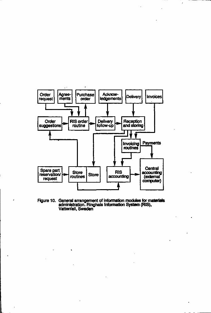
Orderrequest
Agree-ments
Purchaseorder
Acknow-ledgements Delivery Invoices
Ordersuggestions
RIS orderroutine
IDelivery
follow-upReceptionand storing
Spare partreservation/
requestStore
routines Store
Invoicingroutines
RISaccounting
J
Payments
V
Centralaccounting(external
computer)
Figure 10. General arrangement of information modules for materialsadministration. Ringhals Information System (RIS),Vattenfall, Sweden
4.3. EQUIPMENT PERFORMANCE APPLICATIONS
Computers have been increasingly recognized as tools for improvement of maintenancecapabilities, practices, methods and procedures to supplement the traditional manual intensivemaintenance activities. The goal of the improvement is to reduce the number of unplanned outages,shorten outage length, reduce the cost of repairs, improve plant availability and reduce plantmaintenance costs.
Computers are also used to perform reliability cantered maintenance processes to evaluate plantsystems for maintenance planning. The key steps of the process are: to define the system boundary,partition the system into subsystems (i.e., typically group functionally alike equipment), define theimportant system functions, perform a failure modes & effects analysis or fault tree, and developpreventive maintenance tasks for functionally critical components.
Recent utility implementation of predictive maintenance techniques particularly rely onmonitoring and diagnosis of plant equipment performance status. The monitoring of equipment statusis often related to operations, as described in Section 3. To emphasize maintenance applications, thecomputer-aided monitoring and diagnosis functions are categorized as follows:
• Computer-aided monitoring includes loose parts monitoring, rotating equipment monitoring,thermal performance monitoring, heat rate monitoring, water chemistry monitoring, corrosionand erosion monitoring, piping components fatigue monitoring, vessel integrity monitoring,emergency diesel generator diagnostics, and motor operated valve monitoring, etc.
Computer-aided inspection covers areas of reactor vessel inspection, primary piping,welding inspection, nondestructive examination, piping inspection, steam generatortube inspection, valve inspection and service tools, etc.
Computer-aided surveillance and testing consists of activities such as computerizedprocedures, self-checking and automated testing of reactor protection systems, on-linesignal validation for reduction of instrument calibrations, etc.
4.4. ADVANTAGES AND BENEFITS
The main attributes of a computerized information system that benefits the maintenance of NPPsare:
• The ability к have a master database that contains correct and up-to-date data for use bystaff throughout the NPP,
- The ability to have synchronized databases that can be updated by staff who are authorizedto do so, and to have the updated data immediately available to staff throughout the NPP.
- The ability to have "right information in the right place at the right time" providing staff withan essential resource to enable them to perform work effectively and efficiently.
It is essential to have the "right information" stored in databases. This implies having all therequired information and having all the information correct. This is not achieved easily; it requiresconsiderable effort to put information into databases, and to ensure the information is correct.
Information in the "right place" implies accessibility to the databases from any work locationin the NPP. This is achievable with the use of computer communication systems, e.g. Local AreaNetworks.
54

Information at the "right time" implies accessibility to the data bases at any time of the day,whenever staff need the information to assist (or enable) the performance of work.
A significant benefit to the "right information at the right place at the right time" is that the timeintervals between steps in a work process can be reduced significantly. These "time intervals"represent slack time (dead-time), and if they are reduced, will have a direct impact on the amount ofwork achievable in a given period of time.
Of course the most significant benefit is having correct and appropriate information (the "rightinformation"). This has a direct bearing on the ability of staff to perform quality work, using thecorrect materials, procedures, calibration settings, and so on. The following section lists specificexamples of benefits.
4.4.1. Quality
The quality of work performed can be enhanced.
- Nuclear Safety and Industrial Safety can be enhanced because equipmr ' isolation permits(tagotits) can be managed effectively; radiation dose records are up-to-date and availablewhere needed, and radiation hazard information is available as work is being planned.
- Environmental protection is enhanced because analysis of leakages (and effect on theenvironment) can be done immediately, in real-time as an event is unfolding; and plumeanalysis can be done in real-time, allowing for the correct counter-measures to be put intoeffect.
- Configuration management capability is enhanced because up-to-date engineering data &drawings are always available to all staff; correct spare parts are specified and provided;correct procedures are available; records are properly filed for future reference.
• Procedure compliance is enhanced because authorized procedures are always available; thereis an assurance that correct procedures are used; up-to-date documents are maintained forcalibration information; and documents for QA records, tests and previous maintenance arereadily available.
- Fuel management is enhanced because fuelling is completed according to specifications forreactor core physics and fuel limitations, and irradiated fuel records can be managedeffectively.
4.4.2. Production
The production of electricity from NPPs can be enhanced.
- The duration of outages can be reduced by identifying and acquiring all resources needed(including spare parts, tools, procedures, etc) before the start of the outage; and byperforming critical path planning before and during an outage.
- The risk of forced outages can be reduced when preventive maintenance it performedcorrectly and rii time.
4.43. Cost
The cost of producing electricity can be reduced.
- The inventory of spare parts can be managed to provide the correct spare parts, when they
55

are needed, while controlling the total inventory at an acceptable level.
Productivity improvements can be achieved by developing information systems which reducethe difficulties in getting work done. For example, improvements can be made to the timelyavailability of the right material, tools, procedures and information to the worker at theworkplace.
The throughput of work done can be increased by reducing the dead-time (idle time) betweenthe steps in a business process, and to reduce the time spent waiting to receive the correctpart or procedure. Computers can, for example, eliminate the delays encountered by movingpaper documents from place to place and they permit workers to rapidly search for and findinformation that is stored in the information system.
5. MANAGEMENT OF COMPUTERIZED INFORMATION SYSTEM
5.1. MANAGEMENT OF HARDWARE, SOFTWARE AND DATA
To achieve good management of a computerized information system throughout its complete lifecycle, it is necessary to develop a strategic plan, consistent with the objectives of the utility andconsidering management of information as a corporate asset. This plan must be based on analysis ofthe role that information technology can play to help close the gap between the actual and desiredlevel of performance. Information technology should not be considered by itself but in conjunctionwith the other resources of management (human, financial, organizational). From the results of thisanalysis, precise goals for the information system design and operation should be built into thestrategic plan [15].
An information system gives users a representation of the physical plant which helps them tooperate based on the information derived from the system. Therefore, it is of the highest importanceto maintain consistency Itetween the information system data and physical reality.
An information system has many connections with business organizations. Ongoing evaluationof how the work proceeds is necessary, not only before the startup of die system, but throughout itslife cycle. It is necessary to monitor the evolution of work places and of exchanges between workgroups during the complete life of the system in order to maintain consistency with the workingconditions. The startup of the system is only a beginning and not the end.
The maintenance management system, tightly connected to other systems (financial, humanresources, technical and process, etc.), is one of the main tools of management. Information systemhas to be maintained and it must be prevented from being degraded. Information is a corporateresource, and has to be managed as such. The responsibility for the information should be definedclearly and its effectiveness on the results should be evaluated.
5.2. CHANGE CONTROL
The essence of change control is that all changes are made in a planned and controlled manner,are properly tested, and are only considered complete after all the documentation of die system hasbeen updated. A necessary prerequisite for change control is to have documentation which correctlydescribes the installed base of the hardware and software components of the computer system. Thisdocumentation must be kept up-to-date as changes are made. The change control procedure mustensure that changes are implemented in a planned manner, and that thorough testing takes place toensure that the systems perform correctly after the changes have been made. Back-out proceduresshould be ready in case undesired results occur. While the principles of the change control processare simple and clear, execution of all the necessary steps requires a great deal of effort, determination,
56

and thorough follow up to ensure full compliance.
When modifications are made to on-line software, a rigorous assessment of each change shouldbe made before implementation. The change should be tested off-line, so far as is practicable, andshown to meet specified requirements by written tests. Written authorization should be required beforeon-line operation takes place with the software change loaded in the target computer hardware, anda probationary period of running should be agreed. This should take place during stable and non-critical plant conditions. Written test procedures to confirm the on-line viability of the change arerecommended, and a permanent inclusion of the change must be formally authorized. Wheremodifications to software with a major significance to safety are involved, more extensive proceduresare usual, involving off-site checks of the need for the change and its correctness. The verificationand validation of the change must be assured to the same degree as the original software, although siteconditions may require that different detailed processes take place.
5.3. QUALITY ASSURANCE FOR COMPUTER SYSTEMS
5.3.L QA requirements
The general requirements for Quality Assurance (QA) on nuclear plants are well documentedin IAEA Code of Practice No. SO-C-QA (Rev. 1), Code on the Safety of Nuclear Power Plant:Quality Assurance [80]. These principles are supplemented for software in IAEA Technical ReportSeries No. 282, Manual on Quality Assurance for Computer Software Related to the Safety ofNuclear Power Plants [10].
For management information systems, the QA requirement of IAEA Technical Report Series No.282 cannot be followed in all cases, since extensive commercial software systems must be used. Thefollowing section outlines the processes of QA of current good practice.
5.3.2. Commercial Systems
The necessary QA processes for accepting and using proprietary software from a manufacturerdepend on:
1) The use of a well-proven software system, of wide application, and with minimum change,which should be specifically agreed.
2} The use of established international or national QA standards or policies, e.g. IAEA Technicalreport scries no 282 [10]. QA policies or routines developed by the utility or the vendor couldalso be used if they are in accordance with established QA standards.
3) The establishment of careful procedures for error handling and error correction.
These error handling processes depend on processes of verification, at detail and at global levels.Specific data entry should be confirmed, and data produced should be tracked and controlled byestablished issue, change and reissue procedures. Again, these will generally be consistent with thechange control requirement of IAEA.
The ultimate responsibility for the operational use of the information system has to rest on theuser. The information system will provide a service, which will be as accurate and reliable as ispracticable, but may for all that have residual errors. Specific responsibilities of the human user willinclude responsibilities of plant safety and availability, and part of that must include responsibility forconfirming, to a reasonable extent, that information which is used is correct.
5.3.3. Verification and Validation
57

A basic requirement for computer systems is that system documentation is verified at each stageof production. Each document which defines the design should be produced by a top-down process,in which the functional and design requirements are defined in progressively greater detail. Eachdocument should then be verified to confirm that it correctly represents the requirements of the sourcedocument. For the highest requirement of safety, the verification should be independent, and formallyconducted using check lists and documents with recorded resolutions of any discrepancies.
After completion of the design breakdown, in the form of detailed specifications of hardwareand computer codes, system validation is needed to confirm that the integrated hardware and softwareperform correctly. The definition of functions given in the original requirement for the system mustbe taken, and interpreted into the form of detailed functional tests, test instruction, and expected testresults. The computer system must then be systematically tested to those requirements, and the resultsrecorded and analyzed. Any discrepancies of performance should be formally recorded and correctedthrough change notices, in accordance with the QA procedures. Extensive and detailed guidance onthe verification and validation (V&V) of computer systems is given in 1EEE1012, IEC987 and IEC880[21,22,81].
5.3.4. Qualification of hardware and software
5.3.4.1. Hardware qualification
The hardware qualification of a computer system for a nuclear power plant will depend on itsapplication, and whether it is formally classed as "Important to Safety". Off-line information andsupport systems can normally be procured as off-the-shelf items, operating from standard toleranceelectrical supplies, and housed in offices or a computer centre on site. On-line systems connected tothe process will require a definition of limits of power supplies, frequency and voltage, and of ambienttemperature and ambient humidity, and will require a demonstration or certification that operation isachieved satisfactorily in the limiting conditions. A safety computer system will require formalEquipment Qualification (EQ) to IEC 780 [82] and IEC 980 [83] for environmental and seismicperformance, sufficient for its duty. If computer system components, such as remote multiplexers, arerequired to operate within the containment, demanding temperature and humidity conditions must beshown to be acceptable for periods sufficient for the safety duty. A general guide to accepted practiceis given in 1EC 987 [22]. General practice for hardware qualification of on-line systems will requiresome or all of:
1) Type testing of each class of module to its full operating extremes and full performance inworks.
2) Production testing of modules to production acceptance criteria.
3) Subsystem or un it icsts, and system integration tests to criteria appropriate to a factory assemblyplatform.
4) For critical systems, a formal factory acceptance test, which may require a period of continuoussatisfactory operation under controlled conditions for periods of about a week to a month.
5) For critical systems, testing may be required in the factory at the environmental extremes (0°Cto 5S°C ambient, 0% to 95% relative humidity are representative), and may require specialsupplementary tests for Radio Frequency Interference.
6) Installation on site should normally be followed by customer acceptance testing, which repeatsthe factory tests but from site supplies and under the plant administration procedures.
7) After installation, a period of several months of trouble-free operation should be required, duringwhich time plant signals aie progressively connected and demonstrated to the utility.
58

8) The completed installation should be shown to operate satisfactorily by witnessed demonstrationsof its functions and some form of endurance test.
9) The satisfactory integration of the computer into the total nuclear plant I&C will requirecommissioning tests with plant. During these tests, plant process systems will be operated,alarms will be monitored, and automatic control and protection functions operated in all foreseenmodes, to written test procedures.
5.3.4.2. Software qualification
Software qualification is a growing issue within the process industry. Verification andValidation (V&V) and testing are growing rapidly in formality and rigour, and are being extended toall levels of software design and the total software life cycle [77,78].
The major problem of software qualification for any application is the attainment of confidencein the failure free performance of the software. This is at its most demanding for applicationsimportant to safety. At the present time, techniques are developing rapidly.
Early systems often were assembled in the factory, but rigorous testing was not always possibledue to late production of software. The system installed on site often required on-site developmentof software. Before operation with station plant could be accepted by the utility, a software soak testand demonstration of all facilities was used to give confidence.
Present day systems can often be assembled using system software which has been previouslyused. Where this is possible, the application software and data can be rapidly produced, and a factorytest can be used to demonstrate correct functions of display, logging, recording etc. Nevertheless,utilities should insist on full on-site soak testing and witnessed demonstrations of all facilities beforeoperating with plant.
All modern software for an on-line nuclear station should be independently verified in someway. If this is done, and careful top-down documentation is prepared, very few faults will remain.Such software will operate without failure for periods of over a year, from practical experience. Thislevel of assurance is not sufficient, however, for applications to reactor safety.
For a software application to reactor safety, in addition to the above methods, regulatoryauthorities may require confidence to be considerably enhanced [39,40]. The measures which arebeing used for this include:
1) The animation of the written specification, during development, to confirm the specification iscorrectly written and correctly understood.
2) The expansion of the specification in a Formal Mathematical Notation (e.g. VDM, or Z)[84,85].
3) The formal demonstration or proof that the code corresponds exactly to the formal expressionof (2).
4) Full factory and ui-site testing, in accordance with normal past practice.
5) An independent assessment and certification that the software design, implementation anddocumentation is satisfactory.
6) An analysis of the code, using an automatic tool (e.g. MALPAS, SPADE), [75,86] todemonstrate that the logic required matches the'logic which the code implements.
59

7) A back-compilation, to take the machine-code instructions and generate source languagestatements, which must then be shown to match the source code.
8) Pseudo-random testing of an integrated hardware/software system, to inject representativetransients and to confirm correct responses are made.
Not all the above measures will necessarily be required for any particular application; however,for the highest level of assurance and modification, the majority may be [23,40].
5.3.5. Documentation
The documentation needed for a computer system is defined in IEC 987 [22] and IEC 880 [21],for on-line systems. Design documentation should be produced for the functional requirements, thedesign specification of all hardware and software modules, the detailed module circuits and layout, andthe detailed code for systems important to safety. This information should be fully available in thesystems handbooks and manuals, which should also include full details needed for obtaining spares,and organizing repair or replacement of defective components and modules.
The provision of full documentation to the end user for proprietary systems, systems bought off-the-shelf, and systems important to safety is desirable for the hardware, but may be commerciallydifficult or impossible to arrange where extensive standard software packages are used. Themanufacturer or his agent must be competent to repair failed modules, provide spares and give helpon software operation problems, and must be known to the end user.
Specific information, as project documents, is needed to show installation details andarrangements, cable routing, power supplies etc.
5.4. CONFIGURATION MANAGEMENT AND CHANGE CONTROL
5.4.1. Architecture management and change control
5.4.1.1. Objectives
The use of computers arises generally in separate fields to solve separate problems. However,the overall architecture necessary should:
- give end users a common view of the information system
• allow communication between the different systems
- give to every user valid and consistent data
5.4.1.2. Architecture constraints for designers
To define an architecture according to the previous objectives, leads the designer to studycarefully the following topics:
• Workstations - For technical and financial reasons it is not yet possible to define a uniqueworkstation for all users. Nevertheless, it is necessary to define for each family of end users,a standard workstation and a standard communication interface between applications andusers. The applications developed recently show that passive terminals are being replacedmore and more by intelligent workstations. A good feature is to use the computationalcapacity of the workstations to enhance the capacity of the man-machine interface forapplications of local interest.
60
- Networks - It is necessary to implement an effective and realistic separation between process-oriented network and support-oriented network. The exchanges of information between thetwo networks must be carefully controlled by a "high security" gateway, e.g. working in asingle direction, from the process-oriented network to the support-oriented network.According to the nature of the applications, computers and departmental networks areconnected to the appropriate network.
- Data - Data quality is essential in a computerized system. This requires data standardizationand data management processes to be set up.
The systems developed in the last few years, especially in the maintenance field, show thatcollecting, checking, and entering data on computer systems represent a large amount of work. Thisrepresents a large part of the total cost of the system. Generally, a new system gives management anopportunity to increase the quality of the existing data in documents or drawings.
5.4.1.3. Organization
The complexity and variety of systems on one hand, and the strategic importance of informationsystems on the other hand, gives reasons to modify the existing organization in order to be able tocontrol the entire information system. Generally, modifications are made at three levels:
- Decision level • One person of the top level management team is in charge of informationsystems.
- Consulting level - A committee or a consultancy group, gathering representatives of differentusers, helps the manager in charge of information systems.
- Executive level - The consistency of information systems is ensured by a person or a teamworking full time on this subject.
5.4.2. Standard*
Standards must be used to preserve the ability of systems to communicate and exchangeinformation. The use of standards also facilitates evolution of hardware and software and helpspreserve the previous investment of the company from obsolescence. The problems are not the samefor systems using general purpose computers and for systems nearer the process and directly linkedto it. In the first case, the standards can easily be at the base of developments. However, for thesecond case, standards are not at present available for such systems whose role requires them to reflectthe current state of the plant.
5.4.2.1. Functional standards
Exchange of information needs a common meaning for the entities manipulated by differentcomponents of the information system. The same object has often several possible representations.It is necessary to ensure consistency of all the representations. Internal standards have to be definedby the company, with respect to national and international standards when they exist.
5.4.2.2. Communication standards
An information systems are based on communication. It is important to preserve the integrityof the system during the complete life cycle. For this reason, the designers must respect standards forcommunication with the objective of minimizing the effects of hardware and software evolution.
Standards concerning the data transmission domain are well known. Communication ofinformation between subsystems is not completely standardized today, but standards will begin to
61
appear. It is recommended that the-state-of-the-art in this domain is followed. Utilities have aninterest in defining internal procedures for this class of communication. A rigorous structure for themanagement of the exchange of data will provide a degree of protection from the unavoidable changesof hardware and software in the future.
5.4.2.3. Data dictionary
A data dictionary which defines the meaning and the types of data, their exact format and rangesof validity, is necessary for any application of computers to information systems. Data dictionariesmay be specific to the supplier of the software, and will not necessarily be of a compatible standardwith other suppliers. If, however, standards do not exist, it is important to use market standards, butonly if they have a reasonable chance of enduring.
5.4.2.4. Datastorage
Physical storage follows current standards and is mainly the responsibility of information systemdesigners. For storage of documents, new standards are now being developed and appearing and canbe used with benefit.
5.5. OBSOLESCENCE AND RETROFITTING
As many plant systems and equipment become aged, the issue of obsolescence has become oneof the most important concerns in operation and maintenance, particularly those related toinstrumentation, control, and computer systems. Certain aspects of obsolescence may have thepotential for causing reactor outages or keeping them from regaining power level promptly. Otheraspects of obsolescence could involve long delays in procurement due to re-qualification or licensingactivities. The need to address obsolescence unavoidably leads to upgrading or replacement of theobsolete systems or equipment through retrofitting (sometimes referred to as backfit). Although thereare many and various reasons for retrofitting, retrofitting and obsolescence are directly related becauseretrofitting considerations often constrain or dictate the modification and upgrade process.
In the area of computer technology for operation and maintenance, the obsolescence andretrofitting are related as follows:
- Installation is driven by the requirement or need to improve operator-ir.achine interface
- An upgrade or extension of existing computer-based systems is needed
- Existing systems that are obsolete must be replaced
- Previous analogue systeu.s need to be augmented or replaced
Experience and problems encountered with retrofitting show the following concerns:
- Retrofitting is very complex to perform in operating plants
- It is difficult to work in parallel with the operation of a plant
• Short changeover times are usually mandated to reduce outage durations and costs
- Commissioning and testing must be thorough, but be completed expeditiously
• Training and operator qualification must be done thoroughly
- Communication techniques and open standards tend to develop over time
62
- Verification and validation is necessary but costly
- Operator acceptance may be difficult to achieve
- Regulatory acceptance may be difficult to secure
Lessons learned from the experience lead to the following considerations:
- In retrofitting, the utilities will be likely to use stepwise design changes to directly solvespecific obsolescence problems. This makes it important for utilities to develop an integratedstrategy to deal with many and different parts of retrofitting.
- There is a need for developing understanding of the economic benefit to be derived frommaking plantwide retrofitting improvements using modern computer technology. This willstrengthen utility interest and incentive in planning long-term upgrades.
- In addressing obsolescence issues effectively, the identification of replacement andinterchangeability with modern computer technology alternatives is needed.
In addition, designing future computer systems to minimize the effects of obsolescence on bothsoftware and hardware are key elements for system designers. The design for obsolescence shouldconsider the following factors: configuration and architecture, hardware choices, partitioning or aseof building blocks, software methodology, requirements and specifications, documentation forprograms and users, computer language selections, and modularity design, etc.
5.6. IMPLEMENTATION ISSUES
Implementation of an information system is a major and demanding operation. An informationsystem will be efficient only if operators can be confident in the correctness of information in use andif concerned people are currently trained at the same time to operate with the system. Quality of thedatabases and of the training are, with organization problems, the main points to study beforeimplementation of an information system.
5.6.1. Organization
Introduction of a new information system often has consequences on organizations. It isimportant to integrate tl с organization structure and the work processes in the workplace with the newinformation flow. A difficult but necessary task is the measurement of the consequences ofintroduction of the system on people in the plant. In general, information systems modify in asignificant way relations between workers and groups. It would be a serious error for managementto neglect this asset when an information system is implemented and it could be die origin of seriousdisappointment.
5.6.2. Implementation of databases
In general, data which exists in different databases will not normally be consistent unless aspecific effort is made to ensure the databases are designed to be consistent.
Verification, and in some cases certification of the data included in the databases needs a largeamount of work. For example, in the French nuclear system, the activities to collect, verify and recordthe data of the mainten; nee information system is evaluated as 2,000 man-days per unit. However,work is not often finished in this first step. Management of the plant should then be very careful tomaintain the database consistent with the state of the plant. All modifications have to be reflected onthe database and the initial quality has to be preserved. Maintenance of database needs organizationand resource.
63

5.6.3. Training
The best systems would be completely ineffective if users did not know how to use them.Training requires the mobilization of a lot of resources. Modern information systems represent a verylarge field of activity, products are complex and they include many subsystems. It is sometimesdifficult for a user to find the most appropriate way to achieve a given objective. Initial formationrelating to the French experience represents about 1,300 man-days of training per unit. Howevertraining is not fully achieved with startup of the system. Supplementary training is always necessary,first for new operators but also for those having a first level training. Training has to be included inthe general training for maintenance and operations staff. In the French experience described, theamount of supplementary training reaches 300 man-days per unit each year.
5.6.4. Investments required to achieve results
A computer system cannot solve the existing problems of an organization. It is not possible tobuy and import a ready-made system that will immediately achieve results. It is always necessary toaudit the structures and to analyze the work procedures, modify software and enter data before startup.This study should include all of the users at all hierarchical levels and should report conclusions andrecommendations for acceptance and subsequent implementation.
6. FUTURE TRENDS AND RECOMMENDATIONS
There is a continuing trend in the nuclear power industry to apply computer technology,including expert systems, to various engineering, maintenance and operations functions. Expertsystems technology has a number of unique capabilities which makes it a resource for the utilities.These include programming flexibility, inference capabilities, explanation facility and knowledgestructured according to human models.
The next generation of nuclear power programs has placed significant emphasis on theappropriate use of modern technology for the Man-Machine Interface System. Considerableexperience has been accumulated regarding operation and maintenance of existing designs. Thisexperience provides opportunities to improve fundamentally the safety and operability characteristicsof nuclear plants. Breakthroughs in information and communication technology provide a realopportunity and challenge to exploit these capabilities in a manner that will provide benefits tooperation and maintenance. Specific future trends and recommendations are described in the followingsections.
6.1. ON-LINE AND OFF-LINE DATA MANAGEMENT
The data which is required in on-line systems for display, control and protection to define thedetails of each signal, and the data which is received in off-line systems for information support andmanagement of the plant is very extensive, complex and critical. Some of the data has a central placein safety; for example, the procurement details of a safety plant item or the trip levels included in aprotection system. The advantages of full resolution of the problems of on-line and off-line datamanagement will be improved management control of the plant, and higher confidence in thecorrectness and accuracy of the function of the computers on the plant.
It is recommendei! that careful attention is given to ensuring full compatibility of databases,correct gathering of the data initially and satisfactory verification and control of the data itself.
6.2. DIAGNOSIS AND PROGNOSIS SYSTEMS
Diagnosis and prognosis systems for operator aid calls for a broad and detailed knowledge ofthe dynamic behaviour of processes and systems, experience with disturbance sequences and failure
64

mechanisms, ideas and rules about recovery methods, and operating procedures, etc. Those systemsneed dialogue functions with easy access to the stored knowledge and the ability to explain to the userhow solutions and answers have been achieved. In this context, Knowledge Based Systems havefound great attention [11]. One of the most important enhancements to diagnosis and prognosissystems is to ensure reliable and accurate signal input into the systems. Analytical redundancy willbe an important tool to back up or replace or even enable the necessary cross checks of primaryinformation.
This implies a recommendation for development of on-line simulation models with the abilityfor separation of process anomalies and sensor faults and, consequently, has to be seen tightly alignedto the diagnosis process. Techniques for modelling individual processes should be further developed.Qualitative simulation will be a key to achieving simpler and more robust simulation models.
Filter techniques to connect the models to the process have to be industrialized. In the field ofprognosis, predictive filters will be applied, and coupling of simulation with cause-consequence-diagrams will be investigated in order to realize extrapolation of event sequences. Also, neuralnetworks will be considered as tools for fast recognition of learned scenarios from signal patterns asthey appear.
6.3 COMPUTER-ASSISTED OPERATING PROCEDURES
Computer-assisted operating procedures will minimize the need for paper procedures. Theoperators will use VDU screens that present integrated text, graphics and checklists. The displays willguide them in a systematic and rapid execution of the procedure. A particularly valuable aspect ofthe procedure presentation is an event confirmation field which, at each stage of an event-specificprocedure, indicates to the operator if plant conditions are confirming the correct event diagnosis.Some of the procedures may be "context sensitive" in that the computer will edit and simplify them,based on knowledge of the actual state of the plant (e.g. it will not display an instruction to turn ona pump that is already on, but the status of the pump would be shown because it is key to the successpath of the procedure). Examples are an on-line emergency operating procedure (EOP) systemimplemented at the Canadian Point Lepreau CANDU plant, an expert system which codifies EOP logicrules and links them with plant database for use by training but not for operation [87]. In general,current usage of computer-assisted procedures is minimal and in its infancy, but is a major target forfuture development.
The recommendation is therefore that computer-assisted operating procedures should bedeveloped as research projects and prototypes, and feasibility tested on suitable full-scale applicationswhere these may be possible.
6.4. TOUCH SCREEN CONTROL
Touch screen control is developing rapidly in nuclear power. Typical methods beingimplemented, or intended, involve an overview display with a moveable cursor. The operator selectsa plant area with the cursor. A VDU display is presented with details of that plant. Areas on thatdisplay, or altcmativel) .1 separate display VDU, then show control functions (such as open, close orraise, lower). Touching hose areas, or selection using a cursor, with a confirmation action then causesthe plant action to be tal.en.
Touch screen control has very great advantages of reduction of control room cables, andenhanced flexibility of control. The regulatory acceptance may be difficult, since clear assurance mustbe gained that a selected function is correctly selected and correctly performed, if safety plant isinvolved. The economic and technical advantages are such that touch screen control is certain toincrease.
The recommendation is therefore that touch screen systems are approached with care, and that
65

consideration is given to the problems of system integrity.
6.5. DISTRIBUTED SYSTEMS
The use of distributed on-line systems, with input and output equipment local to plant andconnected by local area network methods will increase. Several subsystems will exist on a plant, eachof which will integrate data collection, control room controls, switchgear and plant control, andautomatic closed loop control functions. Separate systems will be needed for safety functions as wellas non-safety functions. They will operate autonomously, and provide their information to othersystems for on-line display and operator support, and for off-line engineering analysis.
The advantage of such systems is the reduction in cables and the provision of comprehensiveinformation while preserving total electrical and physical isolation with optic fibre. Problems willexist in safety justification and in assessment of common mode risks if software errors could causeseveral such systems to fail.
A firm recommendation arises from the field of distributed systems when Local Area Networks(LANs) are used. For information interchange between partners connected to a LAN the kind ofcommunication protocol is of essential importance. For all communication, given deadlines forsuccessful communication should be met. This requires the implementation of a deterministic LANprotocol if possible. An example which has been used with success on the Sizewell В plant is adeterministic version of the well-known Ethernet system. This is defined in IEEE802.3D [88].
6.6. EQUIPMENT WITH EMBEDDED SOFTWARE
Manufacturers of different types of equipment, e.g. sensors, transmitters and more complexsubsystems such as power inverters, are increasingly using digital computer technology in order toimprove the functionality and efficiency of their products. This development implies that software willbe embedded in the product.
The implementation of computer technology in such items opens up the possibility for datacommunication with higher level systems. This could reduce the cabling and the need for complexdata acquisition systems.
The increased functionality is advantageous but attention must also be paid to the licensing andqualification considerations that may arise due to the embedded software. This is especially importantfor retrofits and replacement of old or obsolete equipment.
6.7. COMMUNICATION SYSTEMS
Communication systems play a key role in rapid development, integration, and efficient use ofdigital systems. A digital system in a power plant may include single-loop controllers, programmablelogic controllers (PLCs), distributed controllers, plant monitoring and data acquisition systems, andengineering, maintenance, and operator workstations. A communication system that connects thesesystems has a significant impact on the present and future operation of a plant. For reliability andoperability reasons, a communication system may consist of several networks.
The recommendation arising is that, to take advantage of powerful applications such asdiagnostics for plant operators, these networks should be integrated. These networks can best beintegrated by having them meet an open standard adopted by nuclear power plant owners. The mostwidely recognized open standard is the International Standards Organization Open SystemsInterconnections.
66

6.8. NETWORK MANAGEMENT
In the future, the computer systems will evolve to a highly decentralized system, cooperatingon a powerful multi-media network system. Networks will in the future, transfer many types of datacoming from various databases, not only from classical alpha numerical or graphical databases, butalso from voice or video databases. One of the main problems will be network management. Today,network management is a growing function in utilities. In a few years it will have first place in theinformation system management. Network management will realize the functions allowing the usersto obtain, at any time, the services they need: access to the servers, implementation of securityrequirements, and control of performance, etc.
Today, these functions are mainly based on human procedures. It is recommended that thedesigner notes carefully the expectation that, in future, they will be automated, and that designs shouldmake full use of this. The automatic network manager will be able to choose the appropriate supportat each time with respect to security conditions, performance needs, availability of servers andmaterials on the network.
6.9. STANDARDIZATION OF INFORMATION EXCHANGE
Networks will be the backbone of the information system. On the networks, servers custom-designed for specific functions would deliver service to the users. It will soon be possible to achievethe vision that all staff in NPPs will, by themselves, be able to access the information they need todo their work when and where they need it.
The technology is available today and is becoming more economical. The concept is that staffwill have access, from any location, to information on parts, procedures, calibration data, etc. Theinformation they access will be up-to-date and correct at all times.
Communication between the servers and the users will need a high level of reliability andavailability. The users must be protected from the change of technology in computer hardware andsoftware or in transmission procedures. The general use of standards is a major need for the electronicdata processing community, but it is of special interest to the nuclear industry where the needs ofreliability and availability are extremely important.
The recommendation arising is that, to reach this goal, it is desirable to adopt die existingstandards, e.g. IEEE or OSI standards. Where these standards do not cover the requirement, it isgood practice to use the commonly accepted industry standards and this can give the designers andthe users a good assurance of durability.
6.10. DATA ЛНСНПI TURE AND MANAGEMENT FOR MAINTENANCE
There is a trend towards defining and developing a total data architecture for the complete datarequirements for NPPs. Such an architecture would define all the data entities and their relationshipsto each other [89,90]. With this it will be possible to identify the master data for each data set, andto assign responsibilities for management and control of the data.
The recommendation is therefore that all information systems should use data from master datasets to eliminate inconsistencies. It will then be possible to ensure the configuration management isachieved throughout the life cycle of the NPP.
6.И. EFFECTIVE VERIFICATION AND VALIDATION METHODS
The increased use of digital technology in nuclear power plants brings with it concerns aboutthe reliability of the associated software, which will perform many functions previously fixed inhardware logic as well as add requested and desired capabilities. Software failures can affect plant
67

safety, reliability and availability. Verification and validation of computer systems will enhance theacceptance of digital systems by users, managers and regulators through increased confidence in thesoftware. Recent experience of implementation of computer systems for safety applications in Canadaand France shows that verification and validation can be costly and delay the schedule of plantcommissioning.
The recommendation is that practical and cost-effective verification and validation methods andtools are developed to help assure the quality of software and to facilitate wide implementation ofdigital systems. Software design and development methods and tools need also to be developed toimprove software quality and to allow the reuse of software modules in other applications, and tofacilitate the development of tools to support automated software development, verification andvalidation.
6.12. CONFIGURATION MANAGEMENT
The essence of configuration management is that there should be a plant information base(drawings, specification, etc.) that correctly represents the approved design basis, and comctlyrepresents the physical plant itself (pumps, valves, wiring, etc.) and its functionality, and the conversemust also be true at all times during the life of the plant.
The information base must be the same as the physical plant and its functionality must be thesame as the information bade. During the life of the plant as changes are made, as maintenance isperformed, as equipment becomes obsolete and is replaced, this equality relationship must be preserved[51].
To achieve this is a daunting task. Computers can assist with management of the databases, butthe information in the databases is only as good as the information which is put into them. Fullachievement of configuration management requires management resolution, adequate support systemsand procedures, and a disciplined approach by all staff of the NPP.
A major contribution to computer technology is the capability of having a master dataset (e.g.of equipment lists, spare part specifications, etc.) that is used consistently by all staff in all aspects oftheir work. This master dataset would enable consistency to be achieved between the components ofthe documentation (drawings, procedures, spare part lists, specifications, etc.) and enable alldocumentation to be modified as changes are made in the plant.
At present, mo.it NPPs h.-ve documentation systems contained in paper and electronic(computerized) media, and frequently each dataset might be stored in more man one database. It isdifficult and time consuming to update all databases and documents for each change, and to keep themall up to date. New computer technology can be used to overcome these difficulties, and systems arebeing developed for new NPPs.
In the future, it will be necessary to be able, at least for safety systems, to guarantee thatinformation and documents are correct and consistent at all times.
At the present time, no system exists that is able to assure the consistency of all the information.This function is performed by the management of the company or of the plant. However, somesystems specializing in certain fields such as control and automation are beg mnmg to appear. Forexample, in the 1300MW French plant, one system is able to automatically generate roe logicalequations from the electrical diagrams designed by a CAD system. This type of solution may beextended to other fields, when the system is defined during the engineering phases of the plant. Untilsystems are able to treat the entire problem, it will be necessary to convince management of the valueof applying resources to achieve .specific improvement using existing systems. Before introducing anew computerized system in the plant, it is necessary to examine it in a general perspective todetermine what it is able to achieve for the desired state of configuration management.
68

6.13. FAULT-TOLERANT DESIGN
Fault-tolerance is a system approach for designing hardware and software to satisfy therequirement of high reliability and availability. For digital systems such as digital controllers, faulttolerance means that the system is designed to protect against single failures. In other words, thesystem is able to identify faults as they occur, isolate the faults, and continue to operate. To achievefault-tolerance, the system is designed with redundancy, including for examples, input and outputmodules, central processing units, power supplies and cooling mechanisms.
Fault-tolerant design for hardware has become a common practice for high reliability on-linedigital controllers and process monitoring computers. On-line digital protection systems have an equalor greater requirement for fault-tolerance and often must be designed to be fail safe.
Since the failure modes for software are different from hardware, fault-tolerant design forsoftware needs to consider the failures caused by common modes effects which may be introducedduring designing or programming. While the assurance of fault-free software is difficult to achieve,regardless of formal verification and validation, software fault-tolerance may require the considerationof functional diversity. This means that duplicate software would be designed, programmed, verified,and validated independently and separately. Alternately, fault-tolerant software may require a backupsystem or a fail-safe option so that if the software fails, it will fail to a safe state as the overall systemrequires. This kind of approach is expected to be extremely costly.
The recommendation is therefore that active research is undertaken to identify the practicalityof software fault tolerant designs, so that arguments of diversity can be used to pre-empt some of theproblems of software reliability justification. It is anticipated that in the future application of digitalsystems, more and more V&V procedures will be required for software to reach a leve! of reliabilityand availability for which they were not previously expected to achieve. The ability for software tobe qualified would certainly be a main constraint in the near future.
7. CONCLUSIONS
The nuclear power industry has often been in the forefront of the process control application ofcomputers, and this has been the case for application to operation and maintenance. However, thepower and speed of computers have only recently become economical and sufficient for someoperations which require frequent updating to match plant conditions. The speed and power now givea firm base for the expansion of computers into many fields on nuclear plants. These include bothsystems on-line to the plant and reflecting plant state directly, and off-line and reflecting plant stateindirectly, using links to other systems and used to support operation and maintenance.
The application areas of significance include:
• On-line support to the operators through man-machine interfaces to show plant states
• On-line control, sometimes of safety significance
° On-line protection and interlock applications, important to safety
« Systems for condition monitoring, prognosis and diagnosis, on-line to specific plantequipment
- Off-line systems, providing information for planning, support, management and operationhistory information needed for efficient plant operation and maintenance.
69

A summary of experience, problems and advantages shows:
1. The use of computer systems for on-line display of plant state to the operators is now common,and retrofit systems with improved performance are being implemented. The flexibility of calorVDUs and the use of structured hierarchies of displays have overcome most of the problems ofearly systems. The use of such systems has major advantages of providing information on thecomplete plant, with the added ability to present summary and calculated information tooperators. Integration of such features as operating procedures into the Video Display Units ispossible.
2. Fault tolerant digital control systems have significant advantages, and have been successfullyapplied to many nuclear plants. These controllers use redundant microprocessors and signalvalidation methods, and provide wide range algorithms with more optimized performance andhigher reliability than the previous analogue controllers. They have been shown to reduce plantoutages and trips, and reduce safety challenges to the plant. Their use will grow, but ib?s maybe inhibited for safety applications by regulatory problems.
3. Computers are being used increasingly to provide integrated and multiplexed operation ofcontrol room controls, with connection to the plant equipment using predefined and protectedlocal area network systems. This provides significant advantages of cable reduction, spacereduction and improvement of safety. All plant interlocks can be implemented into the controland automation of the production of control logic for swjtchgear is possible. Touch-screencontrols in the control room can be integrated into the system. This will be a significant areaof growth.
4. Computer-based systems for protection have been implemented successfully in several countries,but often at costs far higher than expected. The extensive verification and validation .«quiredfor assurance of software accuracy and integrity has been found to cost more than anticipated.The lessons learn J have g- rteral application in the production of very high quality software.The other difficulties have nut generally been those of computer technology, but of regulationand licensing. Th. operational integrity must be demonstrated and assured to very high levels,using demanding methods. These methods, such as formal verification and validation, formaldefinition of requirements, modelling, code proof, code analysis and dynamic testing, are nowbecoming more fully supported by software tools, and die costs will fall. The need to addressobsolescence of existing protection equipment, the attraction of better protection algorithms andthe improved protection which is possible using computers will increase protection applicationsworldwide.
5. The use of proven software in a new application gives problems of assurance of performance.The availability of documentation and of the operating history of software is essential to it»reuse. A commercial software system may have many millions of lines of code, and knownunresolved software problems, yet it can often be used whh full confidence for managementinformation in many organizations. No practicable means of analysis exists to show suchsoftware is suitable for an application in safety or protection, yet such systems may be used forplanning outages, spares and stock control and many other applications important to safety, andsuch uses will increase. The successful and economic use of such software is an essential partof the growth of computer applications.
6. The flexibility of computers for information processing has resulted in their application fordiagnosis and prognosis purposes. Expert system methods including advanced man-machineinterfaces with dialogue functions enable the implementation of complex diagnosis and prognosistasks in an operational environment. The introduction of process related operator aids such asdisturbance analysis, success path monitoring or computerized operation instructions andhandbooks are still in an early stage. However, the use of computers for condition monitoringhas resulted in widespread vibration and special monitoring on reactors and turbines. Operations
70

such as motor start logging, loose parts monitoring, mechanical vessel thermal cycle monitoring,etc., are now routine on many plants. Operation strategies will include more comprehensivelythe concept of predictive maintenance based on such systems, and this can be expected toimprove availability and extend plant life.
7. The use of computers for management of spares gives tangible and intangible benefits. Tangiblebenefits include the reduction of inventory levels by eliminating obsolete material, by takingaccount of detailed use and supply patterns, and by reducing order and delivery delays.Intangible benefits include improved assurance that spares are correct, and mat safety equipmentspares have the correct equipment qualification and quality assurance pedigree.
8. The use of computers for improved management of maintenance outage is significant. The useof "umbrella" concepts allows maintenance of associated plants to be grouped. The planneddelivery of the correct replacement parts and planned work schedules for specialist staff canreduce outage time. These methods can be integrated with the use of proven computer-basedplanning tools extended by the addition of on-line update of progress. Such methods improvesignificantly the records of maintenance made and provided to plant management. This use willgrow, but can depend critically on good design of the databases involved, and theircompatibility.
9. The management of computer systems will reflect the corporate strategy and attitude tocomputers. Unless this is carefully thought through, the necessary support to the plant computermanagement may be lacking, and the system will be less successful than it might be. Keymeasurements of success are the cost of power produced, the improvement in availability andin safety, and the quality of the work on site. The balance of costs and benefits is difficult toquantify in many cases, and may only be possible by consideration of the practicality ofperforming some operations without the use of computers.
10. The regulation authorities will require records and documentation of the processes which involvecomputers, as well as the justification of the computer use as safe where any function importantto safety is involved. This can be onerous. In some cases the volume of documentationinvolved is so great that only a computer system can provide it with confidence.
In summary, the use of computers will increase in all fields, but needs special skills, which areoften scarce. Careful planning, system design, detailed design and software production must befollowed by verification and validation. The system must have adequate long-term support fromsuppliers to cover maintenance, modifications, enhancement and replacement The proper use ofcomputer systems for operation and maintenance will bring significant advantages of safety andeconomy. The use of computers has great importance both for existing plant upgrades, and for thenew designs of reactor anticipated before the turn of the century. AH vendors and utilities must takeinto account the challenge of user acceptance, of implementation and of regulation and licensing ifthese intentions are to succeed.
71

REFERENCES
[I] INTERNATIONAL ATOMIC ENERGY AGENCY, Backfitting for Nuclear Power PlantControl and Instrumentation, Proceedings of the IAEA IWG-NPPCI Specialists' Meeting, 25-27April 1984, Vienna, Austria, IAEA 1WG-NPPCI-84/1, Vienna (1985)
[2] INTERNATIONAL ATOMIC ENERGY AGENCY, Use of Digital Computer Devices inSystems Important to Safety, Proceedings of the IAEA IWG-NPPCI Specialists' Meeting, 28 ••30 November 1984, France (1984)
[3] INTERNATIONAL ATOMIC ENERGY AGENCY, Nuclear Power Plant Instrumentation andControl, A Guidebook, TRS-239, IAEA, Vienna (1984)
[4] INTERNATIONAL ATOMIC ENERGY AGENCY, New Instrumentation of Water CooledReactors, Proceedings of the IAEA IWG-NPPCI Specialists' Meeting, 23-25 April, 1985,Dresden, Germany (1985)
[5] AMERICAN NUCLEAR SOCIETY, Advances in Human Factors in Nuclear Power Systems,Proceedings of the International Topical Meeting, Knoxville, Tennessee, 21-24 April, 1986.
[6] INTERNATIONAL ATOMIC ENERGY AGENCY, Improving Nuclear Power Plant SafetyThrough Operator Aids, Guidelines for Selecting Operator Aids, IAEA-TECDOC-444, IAEA,Vienna (1987)
[7] INTERNATIONAL ATOMIC ENERGY AGENCY, Microprocessors in Systems Important tothe Safety of Nuclear Power Plants, Proceedings of the IAEA IWG-NPPCI Specialists Meeting,10-12 May 1988, London, UK (1988)
[8] INTERNATIONAL ATOMIC ENERGY AGENCY, Man-Machine Communication in NuclearPower Plants, Proceedings of the IAEA IWG-NPPCI Specialists' Meeting, 18-20 October 1988,Schliersee, Germany (1988)
[9] INTERNATIONAL ATOMIC ENERGY AGENCY, Man-Machine Interface in the NuclearIndustry, Proceedings of IAEA/OECD/NEA/CEC International Conference on Man-MachineInterface in the Nuclear Industry, Tokyo, 15-19 February, 1988, IAEA STI/PUB/781, Vienna(1988)
[10] INTERNATIONALATOMICENERGYAGENCY.ManualonQualhyAssmanceforComputerSoftware Related to the Safety of Nuclear Power Plants, TRS No. 282, IAEA, Vienna (1988)
[II] INTERNATIONAL ATOMIC ENERGY AGENCY, Artificial Intelligence in Nuclear PowerPlants, Proceedings of the IAEA IWG-NPPCI Specialists' Meeting, 10-12 October 1989,Hclsinki/Vantaa, Finland, Volumes 1 & 2, VTT Symposium 109 & 110, Espoo (1990)
[12] INTERNATIONAL ATOMIC ENERGY AGENCY, Control Rooms and Man-Machine Interfacein Nuclear Power Plants, IAEA TECDOC-565, IAEA, Vienna, 1990,
[13] INTERNATIONAL ATOMIC ENERGY AGENCY, Nuclear Power Plant Control andInstrumentation 1989, Proceedings of a Technical Committee Meeting Organized by the IAEAand held in Vienna 8-10 May 1989, IAEA, Vienna (1990).
[14] INTERNATIONALATOMICENERGYAGENCY.Computer-BasedAidsforOpemtorSupportin Nuclear Power Plants, IAEA-TECDOC-549, IAEA, Vienna (1990)
[15] INTERNATIONAL ATOMIC ENERGY AGENCY, Communication and Data Transfer in
72

Nuclear Power Plant, Proceedings of the IAEA IWG-NPPCI Specialists' Meeting, 24-26 April1990, Lyon, France (1990)
[16] INTERNATIONAL ATOMIC ENERGY AGENCY, Safety Implications of ComputerizedProcess Control in Nuclear Power Plants, IAEA-TECDOC-581, IAEA, Vienna, (1991)
[17] INTERNATIONAL ATOMIC ENERGY AGENCY, Balancing Automation and Human Actionin Nuclear Power Plants, Proceedings of a Symposium, Munich, 9-13 July 1990, JointlyOrganized by IAEA and NEA (OECD), STI/PUB/843, IAEA, Vienna (1991).
[18] INTERNATIONAL ATOMIC ENERGY AGENCY, Reviewing Computer Capabilities inNuclear Power Plants, IAEA-TOCDOC-561, IAEA, Vienna (1990)
[19] INTERNATIONAL ELECTROTECHNICAL COMMISSION, Design for Control Rooms ofNuclear Power Plants, Standard IEC 964, Geneva (1989)
[20] INTERNATIONAL ELECTROTECHNICALCOMMISSION, Application of Digital Computersto Nuclear Reactor Instrumentation and Control, Standards IEC 643, Geneva (1979)
[21] INTERNATIONAL ELECTROTECHNICAL COMMISSION, Software for Computers in theSafety Systems of Nuclear Power Stations, Standard IEC 880, Geneva, (1986)
[22] INTERNATIONAL ELECTROTECHNICALCOMMISSION, Programmed Digital ComputersImportant to Safety for Nuclear Power Stations, Standard IEC 987, Geneva (1989)
[23] THE ROYAL ACADEMY OF ENGINEERING, Proceeding of a Forum on Safety-RelatedSystems in Nuclear Application, 28 October 1992, ISBN 1-871634-24-5, (1992)
[24] REMLEY, G. W. R., Distributed Digital Processing Technology Applied to Commercial NuclearPower Station Controls, presented at the Conference of "Sizewell В - The First of the UK PWRPower Stations," September 13-14, 1989, Manchester, England; also proceedings of theInstitution of Mechanical Engineers, paper no. C388/014.
[25] ELECTRIC POWER RESEARCH INSTITUTE, Proceedings: 1985 Seminar On Power PlantDigital Control and Fault-Tolerant Microcomputers, EPRI Report NP-4769-SR, September(1986)
[26] ELECTRIC POWER RESEARCH INSTITUTE, Requirement and Design Specifications of aBWR Digital Feedwater Control System, EPRI Report NP-5502, November (1987)
[27] ELECTRIC POWER RESEARCH INSTITUTE, Proceedings: Advanced Digital Computers,Controls, and Automation Technologies for Power Plants, EPRI Report TR-100804, August(1992)
[28] ALE1TE, W., STRUENSEE, S., Regeleinrichtungen und Begrenz ungen von Druck- undSiedewasser-Reaktoren, Atomwirtschaft/Atomtechnik, March (1987), p. 130
[29] US NUCLEAR REGULATORY COMMISSION, Arkansas Nuclear One, Unit 2 SafetyEvaluation Report, USNRS Report NUREG-0308, November (1977)
[30] US NUCLEAR REGULATORY COMMISSION, A Defense-In-Depth and Diversity Assessmentof the RESAR-414 Integrated Protection System, USNRC Report NUREG-0493, March (1979)
[31] Datenblatt zur Leittechnik in Kernkraftwerken No. 16: Kernkraftwerk Grafenrheinfeld,Brennstoff, Warmekraft (BWK), September (1988)
73

[32] Forschungsprogramm Reaktorsicherheit BMFT-RS281: Schutzbegrenzungssytcm mitKleinrechnern (4 DNB-Rechner)
[33] R1ETZSCH, L., The Core Protection Computer System Fitted in Grafeniheinfeld NPP,Proceedings of the IAEA Specialists meeting on The Use of Digital Computer Devices inSystems Important to Safety, November 28-30, 1984, Saclay, France (1984)
[34] RECKWERTH, В., SIEGFARTH, H., SEIBOLD, F., PUHL, V., KLUTHE, K.R., VerbessertesLVU-System fur die Siedewasser-Reaktoren Gundremmingen, Reaktortagung (1990)
[35] BOCK, H.W., HELLMERICHS, K., MERTENS, U., Prufautomatik fur Reaktorschutz- undBegrenzungselektronik, Reaktortagung (1980)
[36] FORDESTROMMEN,N.T. and HAUGSET, K., Integrating Surveillance and Control WithoutOverwhelming the Operator, Nuclear Engineering International, September (1991), p. 41
[37] SUZUKI, K. et al, Coping with the Psychological Impact of Automated Systems, NuclearEngineering International, September (1991), p. 43.
[38] INTERNATIONAL ELECTROTECHNICAL COMMISSION, Nuclear Power Plants -Instrumentation and Control Systems Important to Safety - Classification, Standard IEC 1226,Geneva (1993)
[39] ASMIS, G. J. K. et al, The Canadian Process for Regulatory Approval of Safety CriticalSoftware in Nuclear Power Reactors, presented at the UK Institute of Nuclear EngineersInternational Conference on Control and Instrumentation in Nuclear Installations, May 8-10,1990, Glasgow, UK
[40] HUNNS, D. M. and WAINWR1GHT, N.. Software-based Protection for Sizewell В - TheRegulator's Perspective, Nuclear Engineering International, September (1991), p. 38
[41] HUNNS, D. M. and WAINWRIGHT, Software-based Protection for Sizewell B: TheRegulator's Perspective, proceedings of International Conference on Electrical and ControlAspects of the Sizewell В PWR, September 14-15,1992, UK Institute of Electrical Engineers
[42] INTERNATIONAL ATOMIC ENERGY AGENCY, Protection System and Related Features inNuclear Power Plants: A Safety Guide, Safety Series No. 5O-SG-D3, IAEA, Vienna (1984)
[43] INTERNATIONAL ATOMIC ENERGY AGENCY, Safety-Related Instrumentation and ControlSystems for Nuclear Power Plants: A Safety Guide, Safety Series No. 50-SG-D8, IAEA, Vienna(1984)
[44] SUNDER, R. et al., Experiences and Results with COMOS—an Online Vibration Analysis andMonitoring system, SMORN VI Symposium on Nuclear Reactor Surveillance and Diagnostics,Gatlinburg, Tennessee, USA, May 19-24, 1991
[45] AMERICAN NUCLEAR SOCIETY, 1985 International Topical Meeting on ComputerApplications for Nuclear Power Plant Operation and Control, September 8-12,1985, Tri-Cities(Pasco), Washington
[46] ANS Meeting on Innovative Computer Applications in the Nuclear Industry, Snowbird, Utah,August 31 to September 2, 1987
[47] Frontiers in Innovative Computing for the Nuclear Industry, sponsored jointly by The AtomicEnergy Society of Japan, European Nuclear Society, and Canadian Nuclear Society, Jackson
74

Lake, Wyoming, September 15-18, 1991.
[48] ALE1TE, W., Operator Support by KWU K0NV01 PRINS, AIM Conference, Liege, Belgium,(1985)
[49] BASTL, W., Computerized Aids and Human Factors in Nuclear Power Plant Operation, Whereto Go from Here, International Seminar on Human Interface, Kyoto, Japan, February 22-23,1988,
[50] INTERNATIONAL ATOMIC ENERGY AGENCY, Man-Machine Interface in the NuclearIndustry, Proceedings of IAEA/OECD/NEA/CEC International Conference on Man-MachineInterface in the Nuclear Industry, Tokyo, 15-19 February, 1988, IAEA STI/PUB/781, Vienna(1988)
[51] PARSONS, A. F., MOTTRAM, P. R. and WESTERMAN, M. P., VDU Format Specificationfor Sizewell B, proceedings of International Conference on Electrical and Control Aspects ofthe Sizewell В PWR, September 14-15, 1992, UK Institute of Electrical Engineers
[52] The Evolution of a Computer-Based Reactor Protection System Using a Fail-Safe Mode ofOperation. BNES Conference, Science and Technology of Fast Reactor Safety, London, 1986
[53] MOUTREY, G. B. and REMLEY, G., Sizewell В Power Station Primary Protection SystemDesign Application Overview, proceedings of International Conference on Electrical and ControlAspects of the Sizewell В PWR, September 14-15, 1992, UK Institute of Electrical Engineers
[54] HILLS, B. G., BOETTCHER, D. В., REED, R., Man-Machine Interface and its Implementation,proceedings of International Conference on Electrical and Control Aspects of the Sizewell ВPWR, September 14-15,1992, UK Institute of Electrical Engineers
[55] ALEITE, W., PRISCA, KWU New NPP Process Information System, Nuclear Europe,Sept./Oct. (1989)
[56] ALEITE, W., Leittechnik in Kemkraftwerken, atomwirtschaft (atw), Oktober 1992.
[57] HEINBUCH, H., Erkenntrisse aus dem Betricb mit bildschirmgestützter Informationsdaí stellungund resultierende Anforderungen an zukünftige Warten in Kemkraftwerken (Results from theoperation with VDU information in the control room and resulting requirements for futurecontrol rooms in NPPs), Fachsitzung "Mcnsch-Maschine-Kommunikation", JahrestagungKemtechnik (1991)
[58] ELECTRIC POWER RESEARCH INSTITUTE, Proceedings: 1986 Seminar on EmergencyResponse Facilities and Implementation of Safety Parameter Display Systems, EPRI Report NP-5510-SR, November (1987)
[59] INTERNATIONAL ELECTROTECHNICAL COMMISSION, Measurements for MonitoringAdequate Core Cooling Within the Core of Pressurized Light Water Reactors, Standard IEC911, Geneva (1988)
[60] INTERNATIONAL ELECTROTECHNICAL COMMISSION, Functional Design Criteria fora Safety Parameter Display System for Nuclear Power Stations, Standard IEC 960, Geneva(1988)
[61] ÕWRE, F. and FELKEL, L., Functional Description of the Disturbance Analysts System for theGrafenrheinfeld Nuclear Power Plant, Halden Project Report HPR 221,14, November (1978)
75
[62] BASTL, W. and FELKEL, L., Disturbance Analysis Systems, State of the Art NATOSymposium on Human Detection and Diagnosis of System Failures, Roskilde, Denmark, August4-8, 1980
[63] EISGRUBER, H., FCLKEL, L. and REINER, H., Main Results of the Reactor InformationSystem Project, Enlarged Halden Program Group Meeting, Strõmstad, Sweden, May 11-14,1987.
[64] BASTL, W., Integrated Disturbance Analysis, a Basis for Expert Systems in Nuclear PowerPlants, ANS Topical Meeting, Snowbird, August 31-September 2, 1987
[65] BASTL, W. and WACH, D., Experiences with Noise Surveillance Systems in German LWR's,Specialists Meeting on Reactor Noise (SMORN III), Tokyo, Japan, 1981, Progress in NuclearEnergy, Vol. 9 (1982), p. 505.
[66] INTERNATIONAL ELECTROTECHNICAL COMMISSION, Acoustic MonitoringSystems for Loose Parts Detection - Characteristics, Design Criteria and OperationalProcedures, Standard IEC 998, Geneva (1990)
[67] FELKEL, L., SCHULLER, H., EISGRUBER, H., and HOFFMAN, H., Application of anAdvanced Software Concept for Operator Aids in Nuclear Power Plants, Computer Applicationsfor Nuclear Power Plant Operation and Control, ANS International Topical Meeting, Pasco,Washington, USA, September 8-12, 1985
[68] SMORN V, Minich 1987, Progress of Nuclear Energy, Vol. 21, Pergamon Press (1988)
[69] RIPLEY, M. J., Basic Concepts of the Station Automatic Control System Design for SizewellВ Nuclear Power Station, proceedings of International Conference on Electrical and ControlAspects of the Sizewell В PWR, September 14-15, 1992, UK Institute of Electrical Engineers
[70] JOHNSON, A., Johnson, The Implementation of Sizewell В Automatic Control Systems,proceedings of International Conference on Electrical and Control Aspects of the Sizewell ВPWR, September 14-15, 1992, UK Institute of Electrical Engineers
[71] STORY, D. T., The Implementation of a Centralized C&I System for Sizewell В Power Station,proceedings of International Conference on Electrical and Control Aspects of the Sizewell ВPWR, September 14-15, 1992, UK Institute of Electrical Engineers
[72] COOK, B. M., and ROBINSON, D.E.P., Sizewell Integrated System for Centralized Operations:Getting it All Together, proceedings of International Conference on Electrical and ControlAspects of the Sizewell В PWR, September 14-15, 1992, UK Institute of Electrical Engineers
[73] PERCIVAL, C. and BRADBURY, D., Bradbury, The Engineering Specification Design andImplementation of the Sizewell В Reactor Secondary Protection System, proceedings ofInternational Conference on Electrical and Control Aspects of the Sizewell В PWR, September14-15, 1992, UK Institute of Electrical Engineers
[74] BEITS, A. E. and WELBOURNE, D., Software Safety Assessment and the Sizewell ВApplications, proceedings of International Conference on Electrical and Control Aspects of theSizewell В PWR, September 14-15, 1992, UK Institute of Electrical Engineers
[75] WARD, N. J., The MALPAS Verification of Safety Critical Software, International Conferenceon Control and Instrumentation in Nuclear Installations, Glasgow, UK, May 1990, Institute ofNuclear Engineers
76

[761 TOOLEY, P. and STOKES, P., Dynamic Testing of the Primary Protection System, proceedingsof International Conference on Electrical and Control Aspects of the Sizewell В PWR,September 14-15, 1992, UK Institute of Electrical Engineers
[77] ARCHINOFF, G. H. et al, Verification of the Shutdown System Software at the DarlingtonNuclear Generation Station, presented at the UK Institute of Nuclear Engineers InternationalConference on Control and Instrumentation in Nuclear Installations, May 8-10,1990, Glasgow,UK
[78] PARNAS, D. L. et al, Reviewable Development of Safety Critical Software, presented at theUK Institute of Nuclear Engineers International Conference on Control and Instrumentation inNuclear Installations, May 8-10, Glasgow, UK
[79] ANDERSON, A., Computer-based Support for Operation, Maintenance and Management,Ringhals NPP, Viittenfal, Sweden (1992)
[80] INTERNATIONAL ATOMIC ENERGY AGENCY, Quality Assurance for Safety in NuclearPower Plants, Code of Practice 50-C-QA, IAEA, Vienna (1978)
[81] INSTITUTE OF ELECTRICAL AND ELECTRONICS ENGINEERS, Standard IEEE 1012
[82] INTERNATIONAL ATOMIC ENERGY AGENCY,IEC780 (1984) Qualification of ElectricalItems of the Safety System for Nuclear Generating Stations.
[83] INTERNATIONAL ELECTROTECHNICAL COMMISSION, Recommended Practices forSeismic Qualification of Electrical Equipment of the Safety System for Nuclear GeneratingStations, Standard IEC 980, Geneva (1989)
[84] JONES, С. В., Systematic Software Development Using VDM, Prentice-Hall International Seriesin Computer Sciences, ISBN 0-13-880725-6
[85] SPIVEY, J. M., The Z Notation - A Reference Manual, Prentice-Hall Series in ComputerSciences, ISBN 0-13-983768-X
[86] The STARTS Guide, A Guide to Methods and Software Tools for the Construction of LargeReal-Time Systems, National Computing Center, Oxford Road, Manchester, M1-7ED, ISBN 0-85012-619-3
[87] ELECTRIC POWER RESEARCH INSTITUTE, Emergency Operating Procedure TrackingSystem, EPRI Report NP-5250M, June (1987)
[88] INSTITUTE OF ELECTRICAL AND ELECTRONICS ENGINEERS, Information ProcessingSystems - Local and Metropolitan Area Networks • Part 3: Carrier Sense Multiple Access withCollision Detection (CSMA/CD) Access Methods and Physical Layer Specification, StandardIEEE 8802-3 (1992)
[89] DATAPRO INFORMATION SERVICES GROUP, Management, Planning and Control ofDatabase, DATAPRO 4425 (1991)
[90] FINKELSTEIN, C, An Introduction to Information Engineering, Addison Webley, (1989)
[91] NUCLEAR INFORMATION AND RECORDS MANAGEMENT ASSOCIATION, PositionPaper on Configuration Management Programs, PP02-1989 (1989)
77

ANNEX
Reports on the Use of Computer for Nuclear Power PlantOperations and Maintenance
79

DATA MANAGEMENT AS A PREREQUISITEFOR CONFIGURATION MANAGEMENT
ALAN COOKBruce Nuclear Power Development,Ontario Hydro, Canada
Abstract
This paper starts by discussing some real problems that are occurring with data that is being copied andmodified. An example is given which involves "Equipment Codes". Root Causes of the problem are identified.Then, Principles and Analogies are developed that help with the understanding of the need for DataAdministration. This is followed by development of Data Management Concepts, and an examination of thefoundation required for Document Management, and for Document Integrity. The link is then made toConfiguration Management. Under "Suggested Solutions", a number of practical steps are outlined, completionof which would lead eventually to sound Data Management which would in turn make it possible to achieveConfiguration Management.
1. BACKGROUND
1. I will use as an example, the data concerning Equipment Codes and Material Codes.
2. We completed the Bruce Information Management System (BIMS) Project at theBruce Nuclear Power Development (BNPD) in December 1991.
We loaded data into data bases for Equipment Spare Parts (ESP), Material ManagementSystem (MMS), and Work Management System (WMS).
ESP/WMS * - equipment codesMMS * - material codes
... following an intensive program of data conversion, data clean-up, and data entry whereneeded.
... and did this for all Departments at BNPD (Bruce NGS A, Bruce NGS B, Bruce HeavyWater Plant (BHWP), and BNPD Services.
3. Part of the BIMS Project was to install a Site-wide data communication network,complete with about 29 Servers and to which about 1800 PC's are connected.
4. The BIMS systems uses a propriety database, IDMS*, but Users have found it doesnot meet their needs and expectations.
Certain groups of Users have used the network/PC technology to "download"Equipment Code data into PC/Server based databases and are working with this data(eg., adding to it).
5. At this point in time, we have a number of data sets on Equipment Codes, no one ofwhich is truly the Master Data Set.
Refer to Section 9, Definition of Acronyms.
81

2. SOME PROBLEMS
We have (1) Data Admin problems, but mote importantly, we have (2) Nuclear Businessproblems.
1. Data Admin Problems
1. Multiple data sets.2. "Master Data Sets" not properly defined and maintained.3. Data integrity problems.
2. Nuclear Business Problems
1. Cost - eg., cost of multiple data bases and platforms to support them.2. Productivity - eg., effort being diverted to get the data a User needs.3. Configuration Management - eg., we could loose control of the data which is
basic to Configuration Management - equipment codes and correctly linkedmaterial codes.
Example:
There is no single Equipment Code (EC) set for a Station which has been designated andmaintained as "complete & correct".
Therefore, we have multiple "Station EC Sets" none of which are complete &. correct,meaning:
... when attributes change eg., functional requirements
or when associations change eg., material/equipment associations
or when changes are made eg., additions/deletions/ modifications
then multiple data sets should be changed, but this is not always done.
eg., Pressure switch on Heat Transport System
was recalibrated to meet an AECB commitment
later it was returned to the original calibration during a routine call-up (using"old" set-point data)
this led to a contravention of a Regulatory commitment
3. ROOT CAUSES (OF PROBLEMS)
Fjrst, some symptoms
The Equipment Code data is the base on which many systems depend.Let's call a complete set of Equipment Codes for one Station, a "Station EC Set".
82

We typically have a Station EC Set built into a number of Application Systems:
1. Work Management System2. Material Management System3. Equipment Spare Parts System4. Flowsheets5. Operating Manuals6. Training Manuals
and we will be building them into
5. Configuration Management Systems
6. Environmental Qualification (EQ) System
We typically have parts of the complete sets built into
valve listair supply listsinstrument listselectrical listscalibration recordsetc.
1. The Station EC Sets, for the varüous Application Systems, run on or appear in:
a numb- ,• of dat bases and document systems:IDMS diabase (on mainframe)Q&A database (on PC's)Interleaf (on workstations)CAD (for Flowsheets)Oracle (on mainframe, Servers and PC's)Foxpro (on PC's)Sybase (on Servers and PC's)
... are supported by a number of IT platforms:mainframesserversworkstationsPC's
... and run under a number of operating systems:MVSDOSOS/2Unix
... all of which (or most of which) can now transfer data via Networks (WAN's, SAN's ftLAN's)*.
• See Section 9, Acronyms.
83

ROOT CAUSE
We have provided for the creation of data, and the interchange of data, by providing thetechnology (eg., workstations and networks) and application systems, bjg have largely ignored the"management of the data itself*.
This is largely because our justification and approval processes focus on acquiring technologyand applications systems. We specify the requirements for technology and applications, but we do not(in general) specify data management requirements.
We have few controls (if any) on the selection of data bases and design of applications, or onhow data is administered, or on how data is structured.
Whv are we in this Situation?
1. Urgency ("solutions are needed now!")2. Individual Budgets ("we will do what we need to do, and we have the money!")3. Easy availability of software4. No rules governing the work of Consultants5. No enforced Policies and Procedures for Data Management6. No Data structure defined for a Division, Branch, or Corporation7. Etc.
4. SOME PRINCIPLES (AND ANALOGIES)
1. Highway Analogy
Compare:
Versus
2. Yellow Pages
Compare:
Versus
3. Warehouses
Compare:
Versus
Highways vs Networks"a high degree of Regulation and Discipline leads to freedom to travel Safelyon Highways"
"a high degree of compliance with Policies à. Procedures, and UserDiscipline, leads to freedom to send and receive information across the datanetworks reliably, and when needed"
Yellow Pages vs Meta data. "Yellow Pages help you find "IT, whatever "IThappens to be!"
"A Data Directory will allow the User to find where the data he/she needs, isstored".
Warehouses vs Data Warehouses. "Warehouses manage material for orderlyreceipt and delivery and protection".
"Data warehouses manage Data for orderly receipt, delivery, and protection".
84
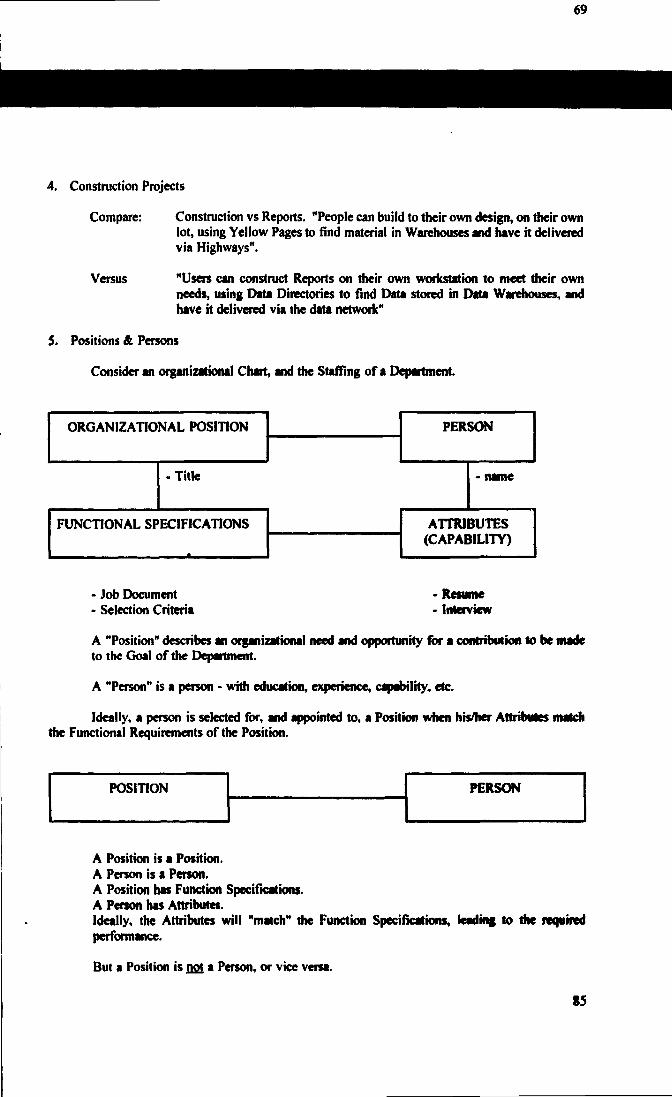
69
4. Construction Projects
Compare:
Versus
Construction vs Reports. "People can build to their own design, on their ownlot, using Yellow Pages to find material in Warehouses and have it deliveredvia Highways".
"Users can construct Reports on their own workstation to meet their ownneeds, using Data Directories to find Data stored in Data Warehouses, andhave it delivered via the data network"
5. Positions & Persons
Consider an organizational Chart, and the Staffing of a Department.
ORGANIZATIONAL POSITION
• Title
FUNCTIONAL SPECIFICATIONS
PERSON
- name
ATTRIBUTES(CAPABILITY)
- Job Document• Selection Criteria
-Resume• Interview
A "Position" describes an organizational need and opportunity for a contribution to be madeto the Goal of the Department.
A "Person" is a person - with education, experience, capability, etc.
Ideally, a person is selected for, and appointed to, a Position when his/her Attributes matchdie Functional Requirements of the Position.
POSITION PERSON
A Position is a Position.A Person is a Person.A Position has Function Specifications.A Person has Attributes.Ideally, the Attributes will "match" the Function Specifications, leading to the requiredperformance.
But a Position is jjoi » Person, or vice versa.
85
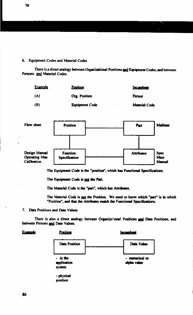
6. Equipment Codes and Material Codes
There is a direct analogy between Organizational Positions and. Equipment Codes, and betweenPersons and. Material Codes.
Example
(A)
(B)
Position
Org. Position
Equipment Code
Incumbent
Person
Material Code
Flowsheet Position
Design ManualOperating ManCalibration
Matbase
FunctionSpecification
The Equipment Code is the "position", which has Functional Specifications.
The Equipment Code is act the Part.
The Material Code is the "part", which has Attributes.
The Material Code is not the Position. We need to know which "part" is in which"Position", and that the Attributes match the Functional Specifications.
7. Data Positions and Date Values
There is also a direct analogy between Organiz&rional Positions anj} Data Positions, andbetween Persons jog Data Values.
Data Position Data Valve
- in theapplicationsystem
- physicalposition
oralpha value
86

Specification Attributes
The Data Position specifies the "Position" of the data, complete with all Data Definitions.
The Data Value is the data residing in the Data Position (the Data Value is analogous to the"Person" or the "Part", previously discussed).
5. DATA MANAGEMENT CONCEPTS
1. "BUSINESS INFORMATION- versus "Information Technology".
"Information Technology" represents the technical world of PC's and workstations, operatingsystems, data base programs, networks, and the like.
"Business Information" represents the information needed to run a Business, i.e., theinformation needed to support operations, decision making, and for reports, etc.
More and more Business Information is being moved from the paper world to the world ofInformation Technology.
However, the Policies and Procedures that were developed to verify and protect paper-basedBusiness Information, should be applied when this runs on Information Technology.
2. "MEDIA INDEPENDENCE", with respect to Policies and Procedures for managing data.
"Media Independence" for Policies and Procedures captures the point the Business Informationneeds to be treated properly (verified, protected, etc.) independent of whether the media handling itis paper or Information Technology.
3. There must be only рд£ Master Data Position, which contains the Master Data Value.
4. There can be copy Data Positions, containing copy Data Values but... a Copied Data Valueequals a Master Data Value "only at the instant of being copied", and is subsequently stale-dated.
RULE: "Change the Master, then re-copy"
PRINCIPLE: "If the Copy is wrong, then the real problem is that the Master is wrong".
5. Data Dictionaries" define the Data Specifications for the Data Positions.
6. Data Maps
"Data Maps" define where the data is stored, especially where the Master Data Positions are.
7. Data Structure
"Data Structure" defines the data entities and associations, and how the data families areassembled.
87

6. DOCUMENT MANAGEMENT
Consider ...
Books & Magazines
Characters
words
paragraphs
books
libraries
Standards
alphabetnumberssymbols
dictionaries
"Rules" forgood construction
meet Reader'sneedsclassificationsystems
Data
characters
strings
blocks
documents
storage
"Books" are an assembly of words and paragraphs.
Definitions...
"A Document is an assembly of strings and blocks".
"For Document Integrity, each string and block muet be declared to be either a Master DataValue, fit a Copy Data Value, and be managed as tuch".
"Document Management it the proper management of all Matter Data Positions (and Values),for strings and blocks, andCopy Data Positions (&Values), and. managementof all the Master-to-Copyrelationships".
This is illustratedin the following diagramfor Document Integrity andDocument Management:
88
Operating Manual #1
Equipment CodeDoc.
S1
III
B1
H
SI
r
сCommitment)oc.
B2
TM. Da
Another ОМ Doc.
E B 3 2II
HI.-I
с.

BI, B2, B3 are BlocksSI is a String
is a Master Data Position
C3is a Copy Data Position
B2 is a Master Data Value(B2) is a Copy Data Value
The "Operating Manual Doc. #1" in the example is an assembly of strings (SI) and blocks(B1,B2,B3).
In the Doc. #1 document, block B2 is a Copy Data Position, and this contains a Copy DataValue, (B2). The author of Doc. #1 must not ("cannot") change the data value (B2) • theauthor must copy this from the "AECB" Commitment Doc".
Similarly, the data value (SI), for a string, is copied. However, Block B3 represents a MasterData Position, and contains the Master Data Value B3. In the example, two other documentsuse copy Data Values, i.e., (B3)'s, and the authors of these two documents must not changethe data values of (B3).
"Document Management" comes from managing the strings and blocks, and their associations(i.e., which is the Master and where are the copies? and for each copy, where is the Masterand where are the other Copies?).
"Document Integrity" comes from managing the Data Values, so that the Master Data Valuesare correct, and copy Data Values are always copied from the Master.
Principles...
"Data Management" is a pre-requisite for "Document Management".
We should start with the basics, i.e., Data Management.
Application software should be judged (assessed) and acquired only if it will help us performthe essential basic tasks of Data Management.
7. CONFIGURATION MANAGEMENT
Consider...
"Information" is an image, of "Reality"
... the drawing is an image, of the object (eg., of a pump)
... the performance data is an image of the performance (eg., of a pump's performance)
89
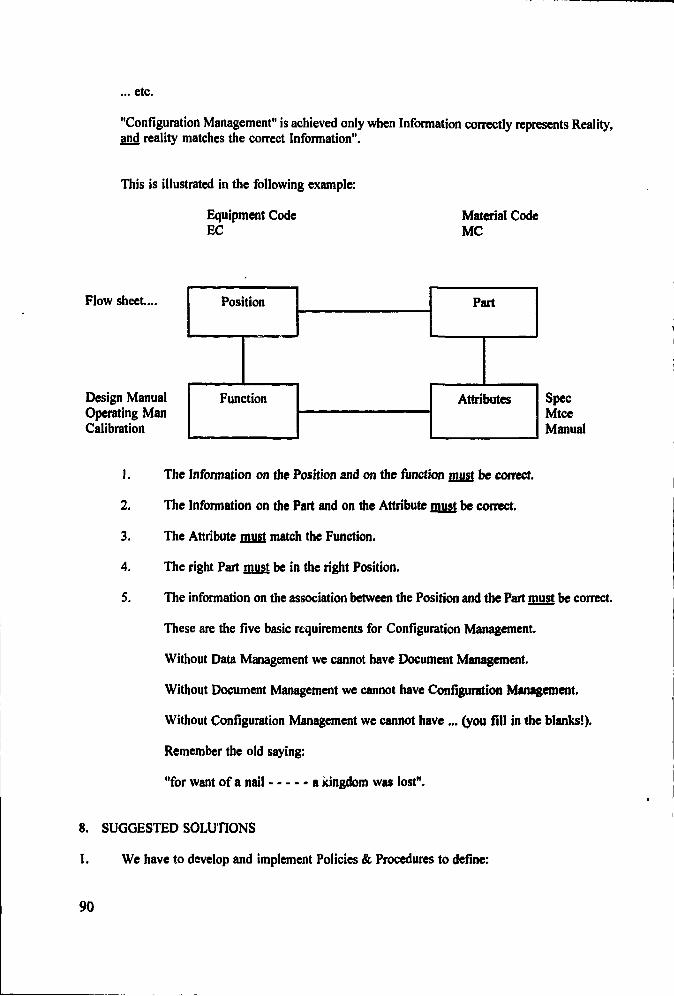
... etc.
"Configuration Management" is achieved only when Information correctly represents Reality,and reality matches the correct Information".
This is illustrated in the following example:
Equipment CodeEC
Material CodeMC
Flow sheet....
Design ManualOperating ManCalibration
Position
Function
Part
Attributes SpecMtceManual
1. The Information on the Position and on the function must be correct.
2. The Information on the Part and on the Attribute must be correct.
3. The Attribute must match the Function.
4. The right Part must be in the right Position.
5. The information on the association between the Position and the Part must be correct.
These are the five basic requirements for Configuration Management.
Without Data Management we cannot have Document Management.
Without Document Management we cannot have Configuration Management.
Without Configuration Management we cannot have ... (you fill in the blanks!).
Remember the old saying:
"for want of a nail a kingdom was lost".
8. SUGGESTED SOLUTIONS
1. We have to develop and implement Policies & Procedures to define:
90

Master Data Sets
Each to be defined by
- Master Data Position
- and Master Data Value
These could initially be in an Application System of choice (arbitrarily chosen).
2. Develop rules for management of Master Data Sets.
3. Develop rules for Copied Data Sets
Where a Copied Data Set comprises a- Copied Data Position
- and a Copied Data Value
4. Develop Data Directories (Yellow Pages)
5. Develop Data Dictionaries (Data Specifications)
6. Develop Data Architecture
7. Establish the capability to distributed Databases on Open Systems8. Develop a Data Management Vision, and a Plan to get us moving together towards
achievement of the Vision.
9. DEFINITION OF ACRONYMS
ESP Equipment Spare PartsWMS Work Management SystemMMS Material Management SystemBIMS Bruce Information Management SystemIDMS Data base by Cullinet, now Computer Associates, on Mainframe computerWAN Wide Area NetworkSAN Site Area NetworkLAN Local Area Network
REFERENCES
[1] Report on Configuration Management in the Nuclear Industry; July 1987, INPO 87-006.
[2] Position Paper on Configuration Management Program; 1989, Nuclear Information & RecordsManagement Association, NIRMA-PP02-1989.
[3] Fundamental Attributes of a Practical Configuration Management Program for Nuclear PlantDesign Control; 1988. Nuclear Regulatory Commission, NUREG CR-5147.
91

THE CONTRIBUTION OF AN INFORMATION MANAGEMENT SYSTEMTO EDF CORPORATE STRATEGY
D. SPOHNProduction Transport,Electricité de France, France
Abstract
The nuclear power plant infonnation system is a chief point in the management of operation andmaintenance of the French nuclear plants. In the first part, different issues are examined. These include: (1)creation of the model and standardization, (2) transparency and security of the infonnation, and (3) systemoperability. Second, the different functions of the information system are presented: The operation subsystemwhich provides operating personnel with information designed to assist them in their decisions; The maintenancesubsystem which is at the center of the information system; The equipment management system designed toprovide plants with the material resources; The financial and human resources management system linked tocorresponding corporate system. Finally, the main components of the technical architecture are presented toaddress the different networks, the evolution of workstations, the servers, and the software architecture.After two years under operation, an infonnation system implemented at EdF has gained the full acceptance ofthe users and has demonstrated its efficiency not only at a qualitative level but also from an economic point ofview.
1. THE NUCLEAR POWER PLANT INFORMATION SYSTEM AND STRATEGY
Electricité' de France is currently confronted with far-reaching changes in the Europeanelectricity generating system. The company must mobilize its full abilities to react and adapt to thechanging environment. Most importantly, EdF must prove its ability to anticipate, in order to offercustomers products that are both compétitif \nd of impeccable quality.
Optimum operation of the nuclear installed base is central to meeting this challenge. Thestrategy defined to achieving this goal is based on three components which provide a framework anda system of reference for assessment of actions to be taken and which guide decisions.
These three strategic components are:
Improve safety
Control production costs
Transform employees into true partners committed to achieving sharedobjectives
This system of reference totally alters the way in which operating problemsare approached. An analysis of the multiple facets of system» is progressivelyreplacing approaches which, in the best of cases, emphasized die craft, or jobcategory, or the immediate result of a task. Or, in extreme cases, work was reduced
92

77
to more or less pertinent application of procedures or simply established routines.
It is pointless to deny the importance of technical aspects in operating anuclear power plant but this plant also plays an economic role: People work there andit has an impact on the environment. All of these facets must be considered whenactions are taken, however minor they might seem. The importance accorded to eachelement, of course, varies but no elements can be simply ignored out of hand.
This approach to nuclear power plant operation makes information an essentialresource and one which contributes to the success or failure of the company'spolicies. A global analysis of a given action requires access to all the informationrequired, as well as the ability to efficiently work with this information.Information ceases to be an instrument of power and once again becomes the object ofcommunication.
For a number of years, EDF has applied significant resources to developing itsinformation systems, particularly at its nuclear power plants. In the past, thismight have been considered an acknowledgment of passing trends. Today, however, theweight of competition, sociological changes, in particular, the rise ofenvironmental awareness, coupled with shifts in the economic and social context,have totally revamped conventional ways of managing a company. Within this context,the information system becomes a strategic management tool.
The information system is based on the way in which the nuclear power base ismodeled. The model is static to represent permanent components or those with acertain degree of performance (such as equipment or structures), and it is dynamicin order to represent and retain transitions. The quality of the model in large partdetermines the place accorded to the information system in the management process.
Before taking a more detailed look at the structure and content of the system,there are a number of issues which should first be examined.
1.1 The Model and Standardization
The first issue concerns the notion of model. Creating a model to represent a complex systemof fifty nuclear power units is an extremely difficult task. Furthermore, the systems-oriented conceptchosen requires that a gi •-•n entity be identified without any ambiguity, whatever the perspective fromwhich it is observed, and that it retain its identity if the perspective changes. Yet, for historicalreasons, each job category has driven changes in its organization according to specific rules.Consequently, it becomes difficult to recognize the unity of an object that is handled by different jobcategories (finances, technical or management, for example).
This problem is aggravated for a system of nuclear power plants since difficulties encounteredat the level of a single unit become impossible when the scope is widened to more than one plant.Modeling supposes that the elements in the model have been standardized. Ensuring that suchstandardization is respected is an organizational problem, as is the management of the informationsystem in general. Unless it is based on rigorously applied standards, the model loses its commonlanguage and thus its meaning. It also loses its value if it is not made pertinent and if it does notreflect the evolution of the plants.
1.2 Transparency яг. I Security
93
The second issue is that of transparency. The information system enables any authorizedperson to access a wide range of data and procedures, the integrity of which is vital to EDF. Overten thousand persons have an operational interface with the system, representing a significant risk ofaccidental (or voluntary destruction).
Since it is out of the question to limit the visibility each person has of the system, since oneof the objectives is on the contrary to offer a broader view, transparency is limited only by theauthorization accorded to each person. The information system itself and the organization establishedmust, therefore, integrate effective responses to problems of security.
13 System Operability
The last but perhaps most important issue involves the size of the information system and itsoperability. In other words, is it possible to effectively operate a system which is supposed to modeleach nuclear power unit down to an extremely precise level of detail (approximately 230,000functional positions pei unit, and is it possible for this system to organize experience feedback for fiftyunits in operation and integrate twenty thousand persons in the information system process?
The solution lies in the type of relations established between the system and the people whouse it. If this interface requires strict and sometimes constraining procedures, these procedures shouldnot arise from the techniques employed. Rather, they must reflect the rules and policies required ofnuclear operators; otherwise, the system must always provide broad areas of unhampered access withinwhich people can exploit their skills and the information available to a maximum degree in order toachieve the objectives assigned to them.
The solution selected is based on the following simple principles.
( 1 ) A set of compulsory "basic laws" designed to maintain the consistency of dialogue from oneunit to another and to guarantee respect for policies set at the national level. This set of lawsincludes the following: Standards used to designate and describe equipment; standards usedto define the form and content of documents, and standard accounting principles.
(2) Accurately defined and stable procedures which establish liaison with other systems orsubsystems that cover specific needs.
(3) Responsibility for the information system or its constituents is assigned to the peopleresponsible for the corresponding missions. The information concerning operating policy andapplicable to the entire installed base is managed at the national level. On the other hand,each plant is responsible for the information concerning it. Likewise, each person or groupof persons is free to use the information to which they have access, so long as communicationprocedures are respected.
Application of these principles is delicate, and is rendered even more complicated since it takesinto account existing information "capital." However, these principles have made it possible for thesystem to gain acceptance. (The first version has been operational at all sites since mid-1991).
2. FUNCTIONS OF THE INFORMATION MANAGEMENT SYSTEM
The information management system for EdF's nuclear power plante consists of foursubsystems, each corresponding to one of the central missions of a nuclear operator: operation,
94

maintenance, financial and human resources management and equipment management.
2.1 Operation Subsystem
The operating subsystem does not have any direct action on the industrial process. It providesoperating personnel with information designed to assist them in their decisions. This system, thus,constitutes an operating aid, even though certain data comes directly from the installation; in particular,data which specifies the status of the unit at a given moment.
Among the key functions of this subsystem are:
Tagging and return to service of equipment to ensure the safety of personnel andequipment
Control conformity to technical specifications following any change in status ormodification of configuration
Perform periodic tests, analyze results and keep records
Requalification of installations before returning equipment to service followingmaintenance work
Fuel management during reactor unloading and refueling
Management of radioactive waste
Management of effluents and their discharge into the environment under normal oraccident situations.
All these functions fall within the scope of plant operation, but most do not involve action byoperating personnel. In particular, it is evident that tagout or requalification operations also involvesmaintenance personnel.
One of the first observations made when the system came on stream was that a new type ofdialogue was established between categories of personnel with different perspectives, such as operatingand maintenance staff. However, this is but one example, and the impact on relations between people,whether they belong to the same functional category or not, has been very strong indeed. The use ofan information system reflects a commitment to strengthen horizontal relations between different areas,different jobs and between people In this example, the system enables people working at differentjobs to benefit from complementary aspects without losing the specific nature of their craft.
2.2 Maintenance Subsystem
The first objective of the maintenance subsystem is to manage maintenance operations. Thisencompasses both operations designed to rectify malfunctions or repair anomalies, and systematicactions taken as part of programs linked to operating periods or the value of certain indicators.
The maintenance subsystem is one of the keystones of the information system. The qualityof maintenance and of the analyses performed both upstream and downstream from maintenanceactions determine the level of safety and unit capability factor. This subsystem makes it possible to
95

schedule operations and control that they are correctly executed. It constitutes a precious source ofinformation for experience feedback regarding both equipment and procedures.
Among the functions performed by the maintenance subsystem are
Monitoring of maintenance operations, from issuing of servicing requests (generallyby the operating team or automatically issued as part of preventive maintenance),through preparation and execution of tasks and archiving of analyses of work done.
Costing of servicing work. This cost analysis is performed when technical ororganizational options are proposed and continues throughout execution. Accountingactions required are generally performed within different time frames than technicalactions, and are integrated in trie financial management system. Consistency betweenthe two subsystems is a problem for which the only satisfactory solution is a highdegree of standardization of communication procedures and adapted standardizationof the entities covered by the system.
Strict control of procedures must be monitored throughout the work. This includescontrol of hold points, certifications, checklists, documentation, etc.
Storage of data on operations and analyses performed during work and managementof the archiving and information retrieval system.
Another maintt <ance-related function (even though there are good reasons to consider it asa separate area) is documentation. This function is designed to provide clear, and up-to-datedocuments to all personnel who need them. The function performs document archiving and updatingin conjunction with equipment backfitting or changes in procedures.
The documentation function is employed for a number of activities, particularly at theoperational level. Even though it is included in the maintenance subsystem, it must provide peoplewho perform other work with the features they require.
To operate correctly, the maintenance subsystem requires a model of the plant that is complete,accurate and regularly updated. Creating and maintaining such a model is a considerable task, sinceeven though most of the information needed is available, gathering, checking and putting it into usableformat can prove extremely costly.
At a minimum, i us model must include:
A detailed description of unit equipment
A parts list
All operating procedures for equipment servicing
Description of rooms and areas where work is performed tin particular, dosimetriccharacteristics)
All installation plants and diagrams
Л model of technical specifications.
96

While this list is not exhaustive, it clearly shows the scope of the problem.
As a key resource for experience feedback, the maintenance subsystem also makes it necessaryto define a common language used to integrate information from different sites and to incorporateapproved terms whenever applicable. This means that strict rules must be followed in representingthe objects treated by the system. These rules cover both the way in which entities are representedand the way in which they are interrelated.
This does not mean, however, that standardization should lead to inflexibility. In particular,the system must be able to easily integrate the specific structure of a given unit. Various ways oforganizing work may coexist at the same site and especially from one site to another. Thesediiferences are the result of historical factors, the local context and even the individual people workingat a site. If they make an effective contribution to meeting the objectives of the overall nuclear powersystem, there is no reason to favor any one of them. On the other hand, the precision of aninformation system, and in this instance of the maintenance subsystem, requires that the organizationbe defined without any ambiguity. If this is not the case, any system malfunction will simplyunderline the weaknesses of the organization.
The maintenance subsystem is linked to all the other components since management ofmaintenance requires full knowledge of the status of the unit.
This information covers availability of equipment which is to undergo servicing, availabilityof the appropriate staff" and replacement parts, impact on technical specifications, maintenance costs,impact on dosimetry, etc. This once again underscores the importance of the comprehensive systemsapproach described above? An operation cannot be isolated within the scope of a given job categorysince it involves cooperation among numerous specialists. The information system must, therefore,provide support for dialogue among these different professionals .
2.3 Resources Management Subsystem
The resources management subsystem is designed to provide plants with the material resources(spare parts, special tooling, etc.) and external human resources they need, when they need them atoptimum cost. At the same time it must ensure consistency with die company's industrial strategy.
This subsystem comprises conventional inventory management functions. For EdF, thismanagement is complicated by the fact that inventory may be spread over several sites. Furthermore,there is centralized management of extremely costly equipment or equipment requiring highlyspecialized skills.
In addition to conventional functions designed to optimize inventories, the subsystem performstracking operations related to industrial policy. For example, it controls the conformity of orders todirectives applicable to suppliers, costs and types of contracts. It also enables analysis of resultsachieved by quality control of services and comparison with results at the safety, availability and costlevels.
These tasks are situât—' on the border between two areas, across which the information systemhelps establish links. On oi>. Je are technicians, whose language is that of equipment or physicalskills, and on the other <t.c accountants and Financial specialists, whose language is money and interestrates. In each of these worlds, every object has a specific meaning and these meanings could end upbeing different if certain precautions are not taken.
97

To establish the desired unity, attention must be refocused on the initial objective. Neitherphysical actic; > nor financial actions have inherent value; their meaning results from the fact that theycombine to achieve the objectives of safety and optimum costs and from the commitment of peopleto achieving these goals. The resources management subsystem makes a substantial contribution ioenabling a horizontal overview of the operations carried out at a plant. This is one of the reasons forwhich it is also one of the most difficult subsystems to define and implement.
2.4 Financial and Human Resources Management Subsystem
The financial management subsystem manages the flow of financial exchanges, checks thatthey are correct and integrates them within the accounting system. It interfaces with the systemswhich perform these same functions at the EdF corporate level.
The system receives economic data from the other subsystems and integrates it in theaccounting system. It U thus able to generate reliable information for employees to enable them toassess the financial value of their actions. To do this, it employs cost allocation rules and checks thatthese rules are correctly applied. These rules are part of a common language and are used todetermine the cost of each action taken. Economic and financial management is, therefore, no longeran instrument only available to accountants, but becomes an indispensable source of information foreveryone.
Management of human resources is associated, albeit somewhat artificially, with financialmanagement. This association has both historic roots, but also results from the financial impact ofhuman resources management in the strict sense of the term. In particular, the subsystem performspayroll tasks and management of benefits .
Human resources management has another objective too, which is to guarantee the bestpossible match between the tasks to be performed and the human resources available. Humanresources information encompasses skills, availability, certification and dosimetry for each employee.
The main functions performed by this subsystem are:
Guarantee that personnel with tl.j skills and certification required are available for aspecific task
optimize the use of skills during a given period
Guarantee that dosimetric risks are compatible with the total radiation exposure ofeach employee
Manage recording of dosimetry data and calculation of collective radiation exposuredata
Manage access to different areas of the site
These functions are linked to operating activities. There are also others related to long-termskills management such as management of personnel training. Hence, the goal is to enable personnelto adapt to new equipment or procedures and acquire additional knowledge within the scope ofindividual training plans.
Within the scope of human resources management, training is not an end in itself. Rather, it
98

is part of efforts to foster social and professional development, which is one of the core éléments ofoverall corporate strategy for the nuclear power generating system. The human resources managementsubsystem has thus been designed to support achievement of the corresponding objectives.
3. TECHNICAL ARCHITECTURE OF THE INFORMATION SYSTEM
The actual information technology resources used for the system play a vital role fat managingsuch a vast flow of information. At the same time, a distinction must be made between the means andthe end. The information system contributes to management of the company, while the computer issimply a tool on which the system operates. It is obvious that the power of modem informationtechnology resources enable ambitious objectives in terms of managing vast exchanges of information.These resources also increase the importance of information systems in the way a company is run.Automated procedures, however, must never be considered a substitute for strategy.
There are three main components in the technical resources which support EdF's nuclearpower plant information system.
3.1 The Network
The main technical component is a data communications network that links all the entities inthe nuclear power plant system.
This network has a dual structure.
There is a wide urea network (WAN) which links all EdF units. This network conforms toall open system interconnect (OSI) standards when these standards have been approved. When thereare no official standards, it conforms to widely accepted market standards. The network, which ismanaged by EdF, uses the public data network as its "backbone."
The second level is a local area network (LAN) within each nuclear site. These LANs enableexchange of information between people at the same sits at very high data rates. They use theEthernet protocol, but can also adapt to other protocols or higher data rates if necessary. Gatewayslink each LAN to the corporate data network.
The network enables any person to access any of the resources connected to the network.While this potential is undeniably one of the main strengths of the system, it is also the source of risksthat are far from negligible. Network administration and access entitlement, in particular, becomesa vital task. Auy failure it. netwi. к administration can lead to serious system problems. Special teamsat both the site and national leul handle network administration. There mission is to guaranteeoptimum operation and respect for operating procedures.
In its present configuration, the network is dedicated solely to data transmission. It has thecapability to evolve to include other applications, however, including multimedia applications,
3.2 Workstations
The workstation is the means by which each person can directly access the information system.The basic workstation consists of a personal computer with an MS-DOS operating system and, to agrowing extent, Windows 3 display. This station performs a number of functions:
99

Emulation of the protocols used by the mainframes connected to the network toprovide access to transactional applications which require substantial processing power
Communication with servers on line in the local area networks
Desktop-based applications that enable the user to exploit the information supplied bythe system (or from other sources)
Integration within a department level LAN for use of a database specific to a giventeam.
Over eight thousand workstations are currently running and connected to the network,accessible by practically all personnel at all nuclear power plants.
3.3 Servers
The last technical component comprises the data servers or applications used. There areseveral different types:
Large processing systems which run databases and applications requiring largedata-handling capacity. These systems have a processing power of approximately 300imps and generally run around the clock, seven days a week.
Local servers running under IWIX, which support local databases. This categorycovers documentation servers, dedicate planning terminals, etc. Like the precedingcategory, they can be accessed from any of the workstations and are available aroundthe clock.
Local OS-2 (or comparable) servers to serve the needs of small teams with specificobjectives.
3.4 Software Architecture
Like the hardware architecture, the software architecture of the EdF system is varied.Whenever possible, it uses off-the-shelf software or programs which can be quickly adapted to avoidany inflexibility resulting from technical options.
While this is relatively easy at the personal computer level, it is more difficult for themainframe software, even though standard products have been selected over custom developmentswhenever possible.
The most difficult problem is exchanging data between systems.
If a global architecture for management of data exchange is not employed, there is a seriousrisk of proliferation of interapplication data transfer applications, to the point that the system wouldrapidly become unusable. This risk is further amplified when older applications are retained and whenthey are situated at points where large amounts of information converge. This is the case with EdF'saccounting system, for example.
This problem has not yet found a fully satisfactory solution, but the fact that the system isbased on a global design has led to definition of logical data structure and application architecture.
100

This architecture makes it possible to progressively integrate specific data exchange interfaces andmigrate towards client-server type architecture.
4. CONCLUSION
The information system for EdF's nuclear power plants has become a key, indeedindispensable, management resource. However, this tool is far from complete, and will, in fact, byits very nature never be totally "finished." It evolves along with the installed base and with thecompany's objectives and it will continue to adapt to its technical environment.
At the same time, in keeping with corporate policy, it must be possible to assess the realcontribution of this system to achieving objectives. This aspect, establishing significant indicators tomeasure the "profitability" of an information system, is rarely considered. Yet, the substantialinvestments required to design, develop, operate and maintain such systems should, no doubt, bejustified. Such indicators will help keep the system focused on its objectives, reveal its weaknessesand adapt the system to external changes.
After two years of onsite functioning, the information system has gained the full acceptanceof its users. The first effects of the system have also been felt: it helps drive the systematicprofessionalism needed for continuous improvement of the quality of technical and managementactions. Its direct impact on costs is difficult to determine so long as the indicators have not beenestablished. However, insofar as the system already makes it possible to determine costs and associatethese costs with corresponding actions, it contributes to overall cost control.
Assessment of the efficiency of this system is currently being examined. The results of thisstudy should show that the system not only makes a broad contribution at the qualitative level, it alsomakes an efficient economic contribution.
101
•EMCHT-SAHMAS H2.0UHM)

DIAGNOSIS SYSTEMS IN NUCLEAR POWER PLANTSDEVELOPMENTS AND APPLICATIONS
W. BASTLL. FELKELD. WACHInstitut fur Sicherheitstechnologie GmbH (1ST),1
Garching, Germany
Abstract
With the progress in on-line digital data processing and the availability of powerful process computersystems a new dimension of plant monitoring has been opened. Besides introducing information presentation bycolor screens and its consequence for control room design, new types of condensed information has been madeavailable by using the potential of computers, e.g. status surveillance, computerized operational manuals, successpath monitoring. One of the important items necessary for these new systems are methodologies to recognizethe deviations from normal operation or normal behavior of components in an early stage. While on-line earlyfailure detection in the beginning have been developed as separate systems (e.g. process disturbance analysis,vibration monitoring), it has been recognized later that they play a key role in plant monitoring and thereforehave to be integrated in the plant information system. In this sense the paper deals with early disturbance andfailure diagnosis and outlines developments and applications in German nuclear power plants, with emphasis onwork performed at GRS and 1ST. Beginning with principles of an overall information concept, the methodologiesand systems are treated in two main chapters: System/process diagnosis comprising system status surveillanceand integrated disturbance analysis, considering also recent progress in developing a real-time on-line expertsystem, and early diagnosis of component failures or malfunctions comprising vibration diagnostics (passivesystems and rotating machinery) and loose parts monitoring. In the appendix basic viewpoints on on-linereal-time expert systems are given.
1. INTRODUCTION
By the progress in information technologies and computer systems today, now tools andmethods are made available, which can be used for further improvement of reactor safety. One of theimportant fields under extensive discussion is the enhancement of the man-machine interface, whichnot only means considering human factors engineered control rooms, but also advanced technicalfeatures to ensure adequate information about the status of the plant. Amongst those new features earlydisturbance and failure diagnosis plays an increasingly important role. This is because knowing aboutplant deficiencies in status nascent provides the maximum time for adequate countermeasures.Consequently diagnosis has two main goals:
to inform the plant staff about arising abnormal deviations of processes (and systems),
to inform the plant staff about the onset of mechanical deficiencies.
The paper deals with developments of the Institute for Safety Technology GmbH (1ST),especially with the results of tests of diagnosis systems in an industrial environment and in practicalapplications. The basic idea is the on-line analysis of selected signal patterns with the aim of assessing
1 a subsidiary of Gesellschaft fur Anlagen- und Reaktorsicherheit (GRS) rnbH
102

the trend of dynamic process behavior or the trend of observed mechanical deficiencies.
2. INFORMATION CONCEPT
In practice diagnosis systems have been introduced step by step in the plants. They have beenused complimentary to the traditional informations available in the control room. Envisaging anadvanced control room adequate integration of the diagnosis provided is essential. This is achieved bya comprehensive information concept.
The basic information concept as shown in Fig. 1 is built up hierarchically and can berepresented as a pyramid. The top level provides information on the momentary plant status, and thebalance between nuclear power generation (core), the heat transfer (primary system) and the heatremoval (secondary system). Parameters such as generator power, thermal reactor power, neutron flux,primary pressure, primary temperature, primary steam flow, steam generator water level are logicallyconnected and displayed in pictorial form.
The second level consists of the necessary information about system states. This applies tosystems, a disturbed state of which can influence nuclear power production, power transportation orpower removal. The cause of the disturbance may be within the special system itself or induced byother (sub)systems. In the demonstration example (see Section 3.2) the information dealt with concernsespecially the feedwater system, steam generation and transportation system, the turbine, thecondensate system, the main coolant pumps and the pressurizer. Additional parameters reflect thestatus of important armatures and relevant flows, water levels, pressure and temperatures. Theinformation allows the operator to follow the effects of a disturbance or of (automatically) initiatedactions.
The third information level deals with single messages and combines important alarms aboutreaching of limits and announcement of dangerous situations. This information is to focus the attentionof the operator on any disturbed part of the plant even when his interest is in the analysis of a specialdisturbance path. Besides announcements of dangerous situations especially messages which informabout an approach to a limit or which initiate automatic actions are of importance.
The bottom level of the hierarchical information structure is formed by the detailed disturbanceanalysis down to the component level. Here preanalysed disturbance sequences are stored within thecomputer in reference models, if a disturbance occurs the operator can immediately get informationabout causes and consequences according to the detailed modelling.
While choosing disturbances for analysis to provide examples, we preferred those which needrelatively many system parts so as to provide a broad analysis spectrum (tank and balance supervision,trend detection, supervision of characteristic curves and gradients). On the basis of evaluation ofoperational experience, first coarse system analysis as well as the possibilities for operator interactions,the following (subsystems were taken into account: residual heat removal system, pressurizer (coolantpressure control), containment isolation, condenser, main and auxiliary condensation system andfeedwater system.
Figure 2 shows all the functions of the 1ST concept of early disturbance and failure diagnosis.The functions which are highlighted by background shadowing will be described in this paper.
103

degreeofdetail
plant status
system status
single messages
detailed disturbance analysis
e.g. treated by component surveillance
e.g. feedwater systemtreated by integrated disturbance analysis
Fig. 1: Information hierarchy
System / ProcessInformation Concept
GENERIS program package
Integrated Disturbance :
" Аау*
Symptom Oriented Displayof Disturbed Plant Situation
" Status Surveillance ofComponents ami Plant Systems ;i
Alarm Reduction
Post Trip Analysis
applications treatedin this paper
MCP: main coolant pump
Component /Partial Process
Surveillance Concept
COIVIOS .MEDEA,ROM ADIS .RAMSES
ï»*#*iv*
JLQQtaè ferta, Leak«ge
Anormaly DetectionTbennobydraulics
Sensor SurveillanceMalfunction, Time Response
Active Safety SystemNIonit.
Repetitive Tests
Early Disturbanceand Failure Diagnosis
Fig. 2:1ST concept of early disturbance and failure diagnosis in NPPs

3. SYSTEM / PROCESS DIAGNOSIS
S\ stem/Process Diagnosis needs powerful computerized operator support systems. Experienceshows that such support systems will be accepted by operators only if they are continuously applicableand not onl\ during certain safety relevant occurrences. This is especially true for early disturbanceand failure detection, where those systems must also be helpful for "normal" operation. We thereforehave to bear in mind power operation (including load follow operation) as well as startup/shutdownoperation.
A major prerequisite for information conditioning and condensation with regard to early failureand disturbance detection is the provision of possibilities for complicated signal processing. This ismade possible by modern computers and color graphic screens. The whole range is available startingfrom simple logical signal combinations up to on-line numerical models of complicated controlalgorithms.
The GENERIS (generic information system) program package [1] was established by GRS.Based on this, five different applications were realized in co-operation with a plant manufacturer(Siemens/kWU) and utilities (NPPs Biblis В and Philippsburg II):
symptom oriented display of disturbed plant situationsstatus surveillance of components and plant systemsalarm reductionpost-trip analysisintegrated disturbance analysis.
Original software development costs for each of these functions would be in the order of US$2 million. Using the GENERIS software package the development costs can be reduced to about 20%of this figure. All applications have been realized in such a way that they can be extended on the basisof additional system analysis.
The presentation of the task oriented condensed information is given by corresponding colorgraphic pictures (on raster displays). Two of the functions realized are of major importance for earlydetection of failures and disturbances and will be described subsequently. Recently GENERIS has beenused as a basis for the development of an expert system working on-line and in real-time. A generaldescription of expert system paradigms & technology is given in the Appendix.
3.1. System status surveillance
A major technical process such as nuclear power plant operation nowadays comprises about10000 - 15000 binary and 1000 - 2000 analogue values to be measured for surveillance, monitoringand disturbance detection. To enable the presentation of a complete overview of the plant status ona color graphic screen and to keep and update a high degree of information, condensation beforepresentation is necessary. To achieve this goal all signals which describe the status of a componentare logically combined in a "status vector". Each of these status vectors may be combined with itstechnologically corresponding partners to form a new status vector which then describes a higher levelsystem.
In an application for the nuclear power plant Philippsburg a total of about 600 of those statusvectors has been defined by the plant vendor (Siemens/KWU). All of these vectors are combined intoa corresponding status signal for each functional unit. As the vector is represented in a "status word"(16 bit), the display system can easily utilize the information provided on components and functional
105

units to determine colors and other status information in plant schematic diagrams. For example,information on the status of a pump (on/off), external/internal fault, power operation/startup/shutdownand also on whether a signal is plausible or not is given by the status vector.
Status monitoring is particularly useful for the evaluation of the type and severity of amalfunction, for assessment of the affected or still available functions and for identification of the mosteffective means of intervention (success paths). The status vector approach represents the newdestination oriented philosophy (with the human operator in mind) as opposed to the traditional originoriented philosophy which displayed whatever was considered relevant at the design stage [2].
3.2. Integrated disturbance analysis
For this application, disturbances, i.e. any kind of deviation from the desired operational statusof the plant or of its components, are registered. Considering the history of signal values, especiallythe gradients of analogue values, it is possible to detect such disturbances from the very start. Usingpreanalysed models for disturbance sequences, operator support is provided for diagnosis as well asprognosis. Normally only those sequences are modelled which provide enough time for the operatorto initiate actions to rectify the disturbance or at least mitigate the effects.
In order to achieve these goals it has been necessary to build up a function orientedinformation structure and a hierarchical presentation scheme which has been realized with colorgraphic overview pictures and trend curves. They have been oriented to the information conceptdescribed in chapter 2. The realization of the integrated disturbance analysis is furthermore based ona pilot project (Grafenrheinfeld NPP) which was carried out some years ago [3]. The information goalsremain unaltered (namely detection of primary causes and prediction/estimation of possibleconsequences) except that now emphasis has been shifted to early disturbance detection. This waspossible because, in the application at the Biblis В plant, we had direct access to analogue processvariables which - as opposed to the Grafenrheinfeld application - permits analysis before some fixedlimits are violated.
Of these applications "integrated disturbance analysis" was chosen for this paper in order toillustrate the type of pictures presented to the operator [4]. Figure 3 gives an example of how the timebehavior of measured analogue variables can be presented. The left part of the picture displays a setof variable names from which the operator (or the system itself) can choose a subset of four variablesfor presentation. For the selected subset the course of the last 30 minutes is shown as well as aprediction for the next IS minutes. If the actual value has reached a given distance from a limit theactual absolute distance in digital format is inserted in the picture as well as the calculated time untilthe limit will be reached with regard to the current gradient. Additionally, text may be highlighted ininformation windows. Figure 4 gives a pictorial overview of the status of the systems of the secondaryside: steam generation, heat and coolant transportation of a PWR. The measured values of the mainvariables are shown (e.g. as bar graphs or as digital values) as well as information on subsystemsstatus and as to whether the necessary signal correlation still persists. The severity of a disturbanceis indicated by a colour coding according to three classes. Further on specific symbols are used toindicate the degree of deviation from normal and the positive or negative trend (gradient) of theparameter presented.
The application was tested with actual process data of an NPP during a disturbance (loss ofmain heat sink). The main result was that valuable additional information can be given to the operator.The next steps of development will be the implementation of a picture hierarchy and an explanationmodule to give the operator the opportunity to go into detailed subsystem information presentation incase of subsystem faults.
106
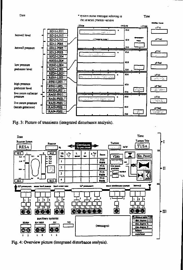
Date
hotweil level
hotweil pressure *
low pressurepreheater level
high pressurepreheater levei
live яеггп collectorpressure
live steam pressure
(steam generator)
• system sums xessages referring to&e seieeieá process variable
•JO ci»
5DÜ-L0IISDÍ2-L0USDU-L01ÎSDU-P005
RH23-H0CM
RH33-L004RH43-L0O*
WE4-M03RH34.L003-
RKOiOOZS
RA0l-P002ví ' . •• - с . : 'X: ' : : ' ';•••'
ne
•50
Fig. 3: Picture of transients (integrated disturbance analysis).
Time
n o
uo
330 .
ПО
«0
5JJJ ,_
«Till
HP н и ш и mua ltd ршпр« Ы ' » а um
•II
auxiliary systemsM « P RN10ПО *У VO
Old1 2 1 2 1 2
(messages!
ЬОшп
Г-Ш
Fig. 4: Overview picture (integrated disturbance analysis).

3.3. Real-time on-line expert system
Researcli work carried out at GRS [5] has resulted in a prototypical expert system integratingthe features that are discussed in the Appendix. Fig. S shows the outline of the expert system whichoperates in an on-line environment, i.e. it gets most of its data from a technical process (the nuclearpower plant). As the results must be available in due time it is also required to operate in the real-timedomain.
The system itself is event-based and generic in the sense that it can be configured to fulfilla variety of different informática) goals. Some are listed below according to increasing complexity:
Alarm ReductionPost Trip AnalysisDynamic Operating Manual (i)System Fault Identification and Analysis (i)Success Path Monitoring (i)Living PSA (i)Qualitative Simulation and State Prediction (i)
The system can be used interactively (i) or non-interactively as the function requires.Interaction means the user is supposed to supply (user-)events to the system whereas in thenon-interactive case events are received only by the process or the system internally. Such a genericexpert system basically consists of three main event sources:
process eventsuser eventsinternal events.
All these events are based on associated objects. Process events report about changes in theprocess. User events initiate some actions or queries in the expert system. Internal events are the resultof stimuli either from the user or the process that had to be postponed (e.g. a pump takes 15 sees, tobuild-up full pressure and so an alarm should only be given if this state is not achieved after thattime). A model to represent this could look like in Fig. 6. Internal events are stored in the so-calledinternal event queue which is embedded at the interface between the models and the reception ofprocess and/or user events respectively.
In the example given in Fig. 6 an event El is generated at time t. This event is listed in theinternal event stream for showing up at time t+15 [sees]. Of course, chances are, the conjunction Clmay not hold any more as the pump might have been closed down again. In such cases the elementEl is simply removed from the internal event stream. It should also be noted that these streams appliedto our models or rather objects, possibly produce another event stream which can in turn be appliedto other objects and so on. Thus the models not only serve to monitor basic events but may beregarded as a filter that conveys only important events to a higher level. This property makes theconcept especially adaptable to hierarchical approaches in either the temporal, topological or functionaldomains.
In conclusion, building an expert system for application to large technical processes requiressoftware paradigms far beyond "iules". Limitation from the "rule"-paradigm cannot be accepted. Thedynamical requirements in on-line and real-time applications need to be satisfied by an integrated andhomogeneous concept. This is not only necessary to cut down software development costs but evenmore so because of licensing and verification problems [6]. However, the power of today's hardware
108

Representation Level (User Reception)
"H | Response
Hierarchy of Models for Transformation/Inference
Internal Events
| | Synchronization/Scheduling "H j "1
Process Events User Events
Stimuli
Representation Level(hardware)
Representation Level(User action)
Fig. 5: Outline of the structure of a dynamical expert system
|Pump on
/
я
P<15bar
J_LND Cl
El(t)
15
sees•
El(t+15)
IOT
Pressurehas not built up properly
Fig. 6: Model with internal events

and lhe great progress in interoperability yields good prospects for the future. A full-fledged systembased on the prototype mentioned above is being developed by 1ST.
4. EARLY DIAGNOSIS OF COMPONENT FAILURES OR MALFUNCTIONS
Similar to the systems discussed before, which provide better information about the overallstatus of the plant by means of process parameter trends and system disturbance analysis, majorprogress has been achieved also as regards surveillance and early failure detection at the componentand equipment level, by applying modern signal analysis methods and advanced computertechnologies. Methods demanding high data compression and high storage capabilities can be appliedtoday economically.
Single or small faults in components may exist and remain undetected or may be non-relevantduring normal power operation, especially in a fault-tolerant system such as a nuclear power plant.However, either potential subsequent failures or demands, in abnormal environmental or processconditions (during an accident) can develop into a more severe situation. An early warning of suchdefects or malfunctions can reduce this risk; the countermeasures can be performed without timeproblems and stress. It is essential for a realistic safety philosophy concept to concentrate efforts indeveloping surveillance and diagnostic systems for components and equipment, since with moderncomputer technology, the necessary prerequisite is there allowing powerful and neverthelesseconomical solutions.
Concerning the mechanical state of the plant, in the past there was little or no directinformation to the operator; he rather had to draw his conclusions from the process behaviorsupplemented just by a few sensors indicating the status of active components. In the seventiesresearch work sponsored by the German Federal Ministries BMFT (research and technology) and BMU(environment and reactor safety) has been performed by GRS and the industry with the aim ofdeveloping methods and systems for on-line assessment and diagnosis of mechanical structures in theprimary system. In particular, emphasis was placed upon the early detection of mechanical deficienciesof reactor internal and primary circuit components. Indirect measuring methods based on acoustic,vibration and process signal noise analysis have been developed successfully.
Loose parts monitoring systems are available in all German nuclear power plants, vibrationmonitoring in all PWRs. Safety standards require these systems and repetitive analyses. Theimportance of early failure detection (EFD) methods has to be seen in the light of the non-accessibilityof most components during operation and of the radiation exposure of the inspection and repairpersonnel during shutdown of the plant. Hints from on-line measurements localizing mechanicaldeficiencies as precisely as possible are of utmost importance for providing spare parts in time andfor preparing the repair strategies. Safety and availability can be increased considerably when EFDsystems are applied correctly, i.e. when careful and detailed signal analysis is performed. For a longtime GRS has concentrated its efforts in this area, in order to enhance the precision and reliability ofsignal interpretation with respect to potential mechanical faults. Current activities are directed towards
gathering operation experiences from different plants in suitable data banks,building up a detailed knowledge base for interpretation of signal patterns and featuretrends andenhancing effectiveness by applying more automated and "intelligent" systems on site.
In Fig. 2 the different methods of the 1ST component surveillance concept are summarized onthe right hand side. Typical for all methods is the use of stochastic primary information; as a
110

consequence much more effort has to be placed on signal analysis and interpretation as compared to"normal" reactor instrumentation. Depending on the problem, analysis methods either in time orfrequency domain are applied. Very often essential information is taken from the interrelations betweendifferent channels (correlation analysis, burst pattern analysis), a typical property of multisensorysystems which generally are coming into use in machinery and process diagnostics.
The overview in Fig. 2 shows the different noise diagnostic methods which have been or arebeing developed at GRS/IST for early failure detection of components or in partial processes. Amongstthem there are methods such as sensor surveillance (signal validation), leakage detection, anomalydetection in processes, active safety system monitoring. In the sequel vibration and loose partsmonitoring will be discussed, since these methods are already used extensively in practice. Theirbenefit has been demonstrated impressively by successful diagnoses and, just recently, considerableimprovements achieved regarding the man-machine interface.
4.1. Vibration and loose parts monitoring
The sensor and instrumentation concept of vibration monitoring systems (SUS) and loose partsmonitoring systems (KÜS) has been published several times [7-12]. the instrumentation and signalconditioning of the SUS are genuine multisensory systems, in the standard version consisting of acombination of 20 vibration sensors (four absolute displacement gauges at the reactor vessel, 16relative displacement gauges at the loops), eight ex-core neutron detectors (noise) and three dynamicpressure gauges in the reactor coolant. Extensive work performed during preoperational tests andat-power measurements with correlation and long-term investigations in several plants as well astheoretical 3-loop and 4-loop model investigations have led to a broad and detailed knowledge base:The v Irrational behaviour is represented now by means of fully interpreted power density spectra withthe mechanical vibration of components allotted to the measured peak frequencies. Acceptable ornon-acceptable (failure-caused) trends and margins of peaks and coherences have been determined orestimated.
Meanwhile a number of successful diagnoses led to a high acceptance of the SUS analyses bythe utilities and the supervising authorities. Examples of such diagnoses [8] are the predictions offailed hold-down springs at the flange of the reactor vessel and of loosened screws at the secondarycore support (flow baffle). Both failure warnings could be given months before the next refuelling sothat the repair could be well prepared. Other examples are described in fl 1] presented at the SMORNV conference: Relaxations of the hold-down spring forces, for instance, could be detected andpredicted in two plants.
The loose parts monitoring systems (KÜS) are multisensory systems consisting of a set ofaccelerometer gauges distributed between the reactor pressure vessel (six sensors) and the steamgenerators (at least two sensors at each generator). The system monitors for metallic impacts withinthe pressure retaining boundary using the audible frequency range. Delay times of bursts in differentchannels and the shapes of these bursts are used for loose parts location and energy/mass estimationby the analysing specialist. For that purpose the burst patterns of actual impacts are displayed with ahigh resolution, for related signals in parallel. The patterns have to be assessed and interpreted usingthe theory of stress wave generation (Hertz theory) and pulse propagation in solid structures and bymeans of experimental results of reference impact tests with known impact energies and impactlocations. A number of events and successful diagnoses performed in the last 15 years have led to abroad acceptance of this diagnostic technique [12].
I l l
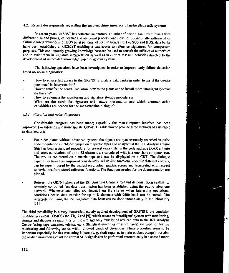
4.2. Recent developments regarding the man-machine interface of noise diagnostic systems
In recent years GRS/IST has collected an enormous number of noise signatures of plants withdifferent size and power, of normal and abnormal process conditions, of operationally influenced orfailure-caused deviations, of KÜS burst patterns, of feature trends etc. For SUS and K.ÜS, data bankshave been established at GRS/IST enabling a fast access to reference signatures for comparisonpurposes. This continuously growing knowledge base can be used to consult the utilities or authoritiesand to assist them in signature interpretation as well as in current research activities directed to thedevelopment of automated knowledge based diagnosis systems.
The following questions have been investigated in order to improve early failure detectionbased on noise diagnostics:
How to ensure fast access to the GRS/IST signature data banks in order to assist the on-sitepersonnel in interpretation?How to transfer the centralized know-how to the plants and to install more intelligent systemson the site?How to automate the monitoring and signature storage procedures?What are the needs for signature and feature presentation and which communicationcapabilities are needed for the man-machine dialogue?
4.2.1. Vibration and noise diagnostics
Considerable progress has been made; especially the man-computer interface has beenimproved. For vibration and noise signals, GRS/IST is able now to provide three methods of assistancein data analysis:
• For older plants without advanced systems the signals are synchronously recorded in pulsecode modulation (PCM) technique on magnetic tapes and analysed at the 1ST Analysis Centre(this has been a standard procedure for several years). Using the code package IRAX all autoand cross-correlations of up to 32 channels are calculated with just one short computer run.The results are stored on a matrix tape and can be displayed on a CRT. The dialoguecapabilities have been improved considerably. All desired functions, coded in different colours,can be superimposed by the analyst on a colour graphic screen and interpreted with respectto deviations from stored reference functions. The functions needed for the documentation areplotted.
* Between the GK.N-1 plant and the 1ST Analysis Centre a test and demonstration system forremotely controlled fast data transmission has been established using the public telephonenetwork. Whenever anomalies are detected on the site or when interesting operationalconditions occur, data transfer for up to 8 channels with 9600 baud can be started. Theinterpretation using the 1ST signature data bank can be done immediately in the laboratory[13].
The third possibility is a very successful, mostly applied development of GRS/IST, the conditionmonitoring system COMOS (see. Fig. 7 and [9]) which means an "intelligent" system with monitoring,storage and diagnosis capabilities on the site and only transfer of reduced data to the 1ST AnalysisCentre (using tape cassettes, telefax, etc.). Statistical quantities (discriminants) are used for featuremonitoring and following trends within allowed bands of deviations. These properties seem to beimportant especially for fast escalating failures (e. g. shaft ruptures in main coolant pumps), but alsothe on-line monitoring of all the normal SUS signals can be performed automatically in a second mode
112
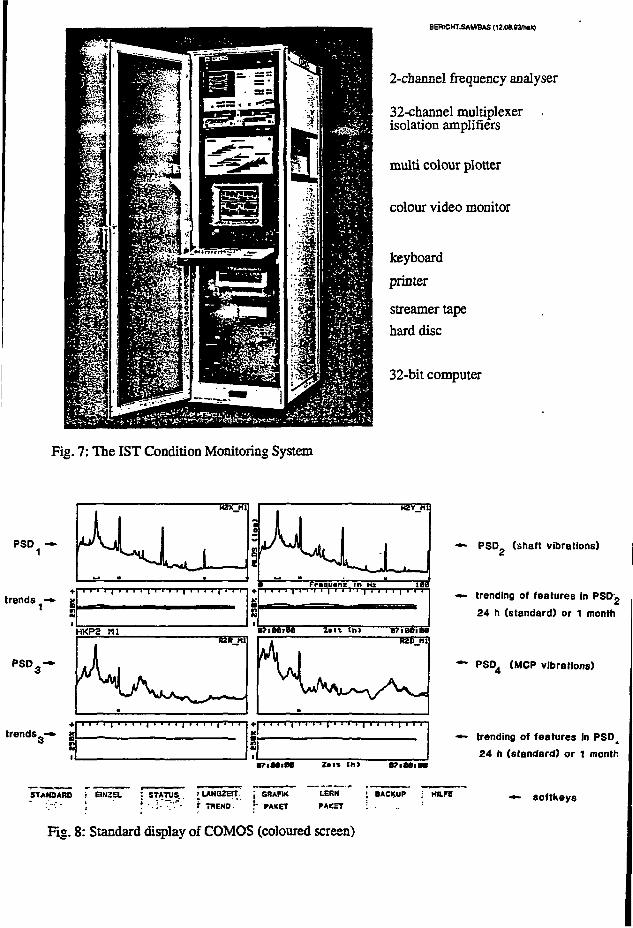
BERICHT.SAM/BAS <12.0в.ЮГМк)
2-cbannel frequency analyser
32-channel multiplexerisolation amplifiers
multi colour plotter
colour video monitor
keyboard
printer
streamer tape
hard disc
32-bit computer
Fig. 7: The 1ST Condition Monitoring System
PSD —
trends -»
trends — «
N
*
nM1
И2Х_111
«
HKP2 MlRZR__H1
1с
gai
к
S
HZT_MI
•_• • . •
1 Fraquanz t n H2 181
a?i8e>ea z>it th> e?tBDieei R2D_f1I
w4r\ L / *_ v A v - !
Ss•
•7iMlM Z.It (h> 87>Ю|В*
PSD£ (shaft vibrations)
trending of features in PSD2
24 h (standard) or 1 month
— PSD4 (MCP vibrations}
••- trending of features in ^
24 h (standard} or t month
STANOARO ! 6IN2EL : STATUS.. ^LANaZEff j
: . - ; " I- '••)• ."•"'- Г TBENO. Г
j GSAKK LEHN ; BACKUP ; HILFEjTBENO. Г РАКЕТ РАКЕТ
Fig. 8: Standard display of COMOS (coloured screen)

(with a lower calculation rate). COMOS systems are already operating in seven PWRs (GKN-1,GKN-2, KKG, K.K.I-2, Biblis A, Biblis B, KKP-2), a further system is in use in the BWR КЫ-1monitoring the vibrational behaviour of the steam turbine.
4.2.2. The Condition Monitoring System COMOS
As a first step in developing COMOS, a detailed investigation of discriminants was performed.Twenty-seven discriminants were tested to see whether they could be used effectively for comparisonof actual and reference features in the vibration spectra. By applying artificial and real noise signals,deviations in frequency, amplitude and peak width were investigated with respect to reliablemonitoring properties.
The hardware of COMOS consists of commercially available equipment. The heart of thesystem is a modern 32 bit computer in conjunction with a two channel frequency analyser. Up to 32signals can be monitored automatically. In the spectra of each signal up to ten frequency bands withadjustable bandwidths (features) can be determined. Margins are set individually around learnedreference states. The trends of the different features (coded by different colours) are displayedgraphically below the spectra. Daily and monthly trend curves can be shown as well as single spectra,quadruple spectra or waterfall representation of spectra history, etc. (menu driven functions).
Two monitoring modes were implemented: in mode 1 signals with possibly fast escalatingfeatures are monitored (e. g. main coolant pump vibrations, 16 calculations per day for 16 signals),in mode 2 the other SUS signals (one calculation per week for 32 signals). The presentation of theresults to the operator is in highly concentrated form, taking into account human mental capacity foroptical correlations (Fig. 8):
the actual spectra of four related signals (i. e. belonging to the same component) aredisplayed on the screen simultaneously, each together with its reference band (in darkcolours) as determined during the learning phase;
related features in the four spectra (e. g. belonging to the same vibration mode) havethe same colours, allowing a fast check, to see if the amplitude has changed (electricaldistortion or real phenomenon);
trend curves of all discriminants calculated from each feature in corresponding coloursbelow the spectra as daily trends, markers for plus and minus thresholds, date andclock for exact time correlation of events.
These are the standard displays automatically switched from one group to the next. Once a dayall spectra and trends are plotted on one document (status plot).
By use of a new information correlation (linkage) matrix, rules for vibrational relations invarious signals and frequency bands can be programmed to realize diagnose properties. Step by stepthe comprehensive and still growing knowledge base can be implemented in on-line monitoring, sothat in a not too far future a diagnosis system in the sense of an expert system for vibration andanomaly monitoring will be available.
4.23. Loose parts diagnostics
For the analysis of KÜS signals the computer based MEDEA system (Fig. 9) is used in the1ST Analysis Centre. It consists mainly of a 16 channel transient recorder, a 32 bit UNIX workstation
114
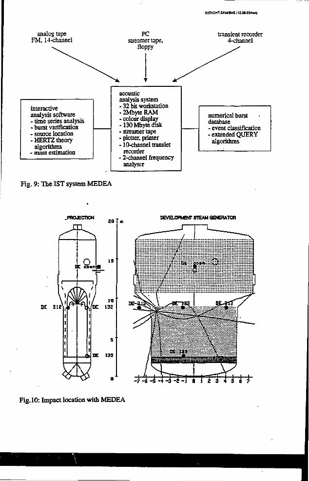
analog tapeFM, 14-channel
PCstreamer tape,
floppy
SERICHT.SAMÍBAS (1гов.вал1«)
transient recorder4-channel
interactiveanalysis software- time series analysis- burst varffication- source location- HERTZ theory
algorithms- mass estimation
acousticanalysis system- 32 bit workstation- 2Mbyte RAM• colour display-130 Mbyte disk• streamer tape• plotter, printer• 10-channel transiet
recorder- 2-channel frequency
analyser
numerical burstdatabase- event classification- extended QUERY
algorithms
Rg. 9: The 1ST system MEDEA
.PROJECTION
DE 312
s
se 13S
оега.срюп- STEAM GENERATOR
--mFig.10: Impact location with MEDEA
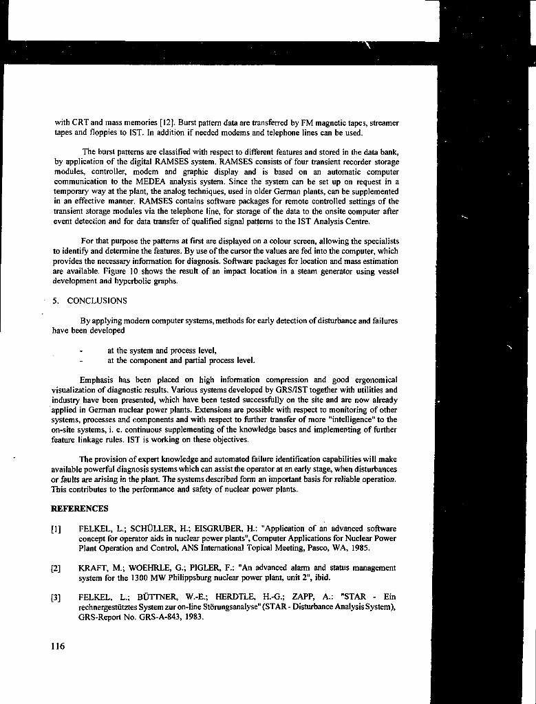
with CRT and mass memories [12]. Burst pattern data are transferred by FM magnetic tapes, streamertapes and floppies to 1ST. In addition if needed modems and telephone lines can be used.
The burst patterns are classified with respect to different features and stored in the data bank,by application of the digital RAMSES system. RAMSES consists of four transient recorder storagemodules, controller, modem and graphic display and is based on an automatic computercommunication to the MEDEA analysis system. Since the system can be set up on request in atemporary' way at the plant, the analog techniques, used in older German plants, can be supplementedin an effective manner. RAMSES contains software packages for remote controlled settings of thetransient storage modules via the telephone line, for storage of the data to the onsite computer afterevent detection and for data transfer of qualified signal patterns to the 1ST Analysis Centre.
For that purpose the patterns at first are displayed on a colour screen, allowing the specialiststo identify and determine the features. By use of the cursor the values are fed into the computer, whichprovides the necessary information for diagnosis. Software packages for location and mass estimationare available. Figure 10 shows the result of an impact location in a steam generator using vesseldevelopment and hyperbolic graphs.
5. CONCLUSIONS
By applying modern computer systems, methods for early detection of disturbance and failureshave been developed
at the system and process level,at the component and partial process level.
Emphasis has been placed on high information compression and good ergonomicalvisualization of diagnostic results. Various systems developed by GRS/IST together with utilities andindustry have been presented, which have been tested successfully on the site and are now alreadyapplied in German nuclear power plants. Extensions are possible with respect to monitoring of othersystems, processes and components and with respect to further transfer of more "intelligence" to theon-site systems, i. e. continuous supplementing of the knowledge bases and implementing of furtherfeature linkage rules. 1ST is working on these objectives.
The provision of expert knowledge and automated failure identification capabilities will makeavailable powerful diagnosis systems which can assist the operator at an early stage, when disturbancesor faults are arising in the plant. The systems described form an important basis for reliable operation.This contributes to the performance and safety of nuclear power plants.
REFERENCES
[1] FELKEL, L.; SCHÜLLER, H.; EISGRUBER, H.: "Application of an advanced softwareconcept for operator aids in nuclear power plants", Computer Applications for Nuclear PowerPlant Operation and Control, ANS International Topical Meeting, Pasco, WA, 1985.
[2] KRAFT, M.; WOEHRLE, G.; PIGLER, F.: "An advanced alarm and status managementsystem for the 1300 MW Philippsburg nuclear power plant, unit 2", ibid.
[3] FELKEL, L.; BÜTTNER, W.-E.; HERDTLE, H.-G.; ZAPP, A.: "STAR - Einrechnergestiitztes System zur on-line Storungsanalyse" (STAR - Disturbance Analysis System),GRS-Report No. GRS-A-843, 1983.
116

[4] BASTL W.: "Integrated Disturbance Analysis (IDA), a Basis for Expert Systems in NuclearPower Plants," in Proc. ANS Int. Topi. Mtg. Artificial Intelligence and Other InnovativeComputer Applications in the Nuclear Industry, MAJUMDAR, D. and SACKET J., eds., p.721, Plenum Press, New York, 1988.
[5] ADRIAN, H.; BÜCHERL, A.; FELKEL, L. et al: "Nutzung der Mõglichkeiten vonrechnergestützten Entscheidungshilfen zur sicherheitsgerichteten Unterstützung der Operateurein Kernkraftwerken" (Application of Computer-Based Decision Aids for Safety-OrientedSupport of Nuclear Power Plant Operators), GRS-Report No. GRS-A-1918, 1992.
[6] ADRIAN, H.; FELKEL, L.: "Licensing of a Post Trip Analysis Program for Use in NuclearPower Plants", Enlarged Halden Program Group Meeting, Bolkesjd, Norway, June 1991.
[7] BASTL, W.; WACH, D.: "Experiences with noise surveillance systems in German LWRs",Specialists' Meeting on Reactor Noise (SMORN III), Tokyo, 1981, Progress in NuclearEnergy, Vol. 9, Pergamon Press, Oxford, 1982.
[8] SUNDER, R.; WACH, D.: "Reactor diagnosis using vibration and noise analysis in PWRs",Operational Safety of Nuclear Power Plants (Proc. Symp. Marseilles, 1982), IAEA, Vienna(1984) 281-299.
[9] SUNDER, R.; VAN NIEKERK, F.: "COMOS - An online system for problem-orientedvibration monitoring", Specialists' Meeting on Reactor Noise (SMORN V), Munich, 1987,Progress in Nuclear Energy, Vol. 21, Pergamon Press, Oxford and New York, 1988.
[10] BAUERNFEIND, V.: "Vibration monitoring of a four-loop PWR, model investigations of thesensitivity of the monitored signals on mechanical failures", ibid.
[11] SCHÜTTE, A.; SOMMER, D.; WEINGARTEN, J.; WACH, D.: "Utility experience in reactornoise analysis in German LWRs", ibid.
[12] OLMA, B. J.; SCHÜTZ, В.: "Advanced burst processing methods in loose parts monitoring",ibid.
[13] RÕSLER, H.: Ein System zur OtUi n.e-1 em Obertragung von Signalen einesSchwingungsiiberwachungssystems (Remotely Control led Online-System for DataTransmission of Vibration and Noise Signals). GRS-Report No. GRS-A-1391,1987.
Appendix
BASIC VIEWPOINTS ON ON-LINE REAL-TIME EXPERT SYSTEMS
About ten years have gone by in which artificial intelligence became a serious candidateeligible for industrial applications, This is due to the fact that first of all computers have become fastenough to process high-level programs and also because goals have been clarified and semantics havebeen shaped so that problems could be described and solutions derived and implemented.
The classical expert systems (i.e. the rule-based ones) have shown their applicability to manydomains, but at the same time exhibited their limitations with regard to their expressive power. Manyparadigms popped up to satisfy particular requirements. Integration efforts were strong, yet, the
117
fig. Z. loi concepi oi eariy uiuuiuoutc aim шише
universal expert system has not been discovered (will it ever be?).
To make things even worse, because hardware permits, on-line and real-time applicationswould enter the stage of possible realization, were it not for lack of methodology to keep up with thedynamical behavior and consistency maintenance in the time domain. In the sequel it is attempted toclarify some of the basic aspects and to show possible solutions to the problems of real-time processmonitoring, diagnosis and prediction.
Most of the proposals originate from research work in the field of reactor safety in Germany.Even though the plant or process usually is a nuclear power plant of the 1200 MWe PWR or BWRtype, the results can be applied to any continuous (non-batch) process.
One of the major components of the approach outlined in the sequel is the process model asone would say in the simulation field. In the expert system domain one rather talks ofknowledge-bases and inferences. In the following chapters the equivalence of these concepts is outlinedand the necessity of integrating them.
I. PROCESS MODELLING
Building models or knowledge-bases is necessary to gather knowledge about the componentsof a process and their interaction. Therefore, the knowledge can be classified into structural andfunctional knowledge, respectively.
The process must satisfy some goal to be considered as meaningful. A nuclear power plantmust produce power at an acceptable level of safety.
A complex process or plant can only be realized by decomposing it into smaller sub-processesthat interact with each other. Fig. 1 gives the generic decomposition of a nuclear power plant. Theachievements of the main goals is assumed to be composed of the achievement of subgoals. Apartfrom the fact that this allows for redundancy it abo accounts for the provision of contingencies, i.e.goals can be reached in several ways. The plant must be started-up, operated, and shut-down, i.e. itoperates in different plant modes.
A model that represents the behavior or the structure of the process can give the operator moretransparency of what is going on, what is going wrong, what may be going wrong, and what can bedone to rectify something that is going wrong.
2. MENTAL MODEL VERSUS KNOWLEDGE MODEL
When operating the plant, the responsible personnel is informed via symbols derived fromprocess instrumentation. From their education and training the operators have developed a so-calledmental model, i.e. a good idea of what, given one state of the plant, it should be in next. Thesubsequent state can be verified by comparing the changes in the instrument readings with theexpectation (prediction) from the operator's model. Although operator error and human factors existthis has shown to be a very reliable configuration. However, it can be improved using knowledgemodels.
Instrument readings tend to be rather limited: lights of different colors, gauges etc. in the oldtimes, CRTs with textual as well as graphical information nowadays. AH only work because a distinctmental model of the operator exists. The operator can only associate in his mind, he cannot see the
118

results of his derivations. Chances are, his performance is improved not in the least from a reliabilitypoint of view, if some way can be found to replicate and visualize his own inference. Here, knowledgemodels can be very helpful.
3. WHAT IS A KNOWLEDGE MODEL?
First of all we must ask, how a process can be described according to specific aspects. Fig.2 shows known process description paradigms and attempts to relate them.
We start out at the process of which an image or model is constructed. We have basically twocategories: structural and functional. The structural models replicate the system topology and allowto answer questions like "where is a specific component", "what are its attributes", when was the lastcheck-up", "how can maintenance or repair be organized". The integrated plant management system(IBFS) [1] is an example which uses such a model (Fig. 3)
The characteristics of such models are they are dynamical in the sense that they provide slotsinto which information can be entered or changed. The main initiator of such changes is the personneland as such the frequency in depth* of such changes must naturally be rather low. However, due tothe fact that many people may access such a system in parallel, the mutual exclusion problem mustbe observed and the frequency in breadth may be quite high. (Frequency in depth vs. frequency inbreadth refers to the chronological changes in one objects as opposed to the relatively simultaneouschanges in many objects.) So, this situation very much resembles a data-base application. Neverthelessthere are significant differences to pure data-base applications: the degree of implications betweenobjects, e.g. one item may not be updated unless some prerequisites have been satisfied, or, theupdates of the items must be performed in a chronological order. As we can already see, the degreeof object orientation is significant. We will come back later to this subject.
The example in Fig. 3 deals with a problem of a damaged pump in the feedwater circuit ofa PWR. We assume that there were means to identify the situation. As a consequence this pump mustbe replaced in due time to avoid unnecessary plant outage. Because there are three redundant pumpsof this kind in the PWR, two of which need to be operational, a plant shutdown is not required forthe time being.
The pump is identified by XI to avoid contusion with the pump with which it should bereplaced, i.e. X2. The pumps are all listed in a database with specific attributes, especially theirlocation. The problem then is to devise a plan for replacement, observe constraints and monitor thecarrying-out of the plan. This plan essentially consists of a succession of events, necessarilychronologically ordered. At every point in time, the responsible management is informed about thestate of the task executing and about the whereabouts of the respective pumps. The pumps are listedas records in the database. These records change attribute (location of XI changes from plant toworkshop to inventory, whereas X2 goes the other way round) However, it would not be possible toreplace pump XI by X2 unless XI was removed prior to the task of installing X2.
Even though, the concept used here is already very powerful it has its shortcomings as it doesnot integrate the items (database records, objects) and events in the plan, and because it does not takeevents from the process directly into account (for instance, something may happen that is prohibitiveto the continuation of the plan). Moreover, the IBFS is realized on the basis of a commercial databasesystem which also includes limitations from its implementation.
119

4. FUNCTIONAL MODELS
A process or a component thereof is something that "works" in a specific way. We can seethis either by the result it produces (like machines that move, or some product that is being broughtto existence) or we have to measure parameters that are otherwise invisible, to make them perceptibleto the human senses. The main sense utilized is vision. We can see current and voltage on meters andgauges, as well as pressure, levels etc. The interactions or relations of these parameters tell us whetherthe process works, i.e. performs its intended function. We can describe these relations either becausewe used them to design the process or we have, after the construction of the process, found certaincharacteristics in the relations of these parameters.
There is no unique way of description of the behavior. The description is governed by severalparameters the most important of which is purpose, i.e. we must know what we would like thedescription to use for. Another one is degree of required precision.
A classical term for the description of the process behavior is simulation or, more precisely,simulation model. Simulation models can be represented in several ways. Two of the most importantare mathematical or physical.
4.1. Mathematical Representation
A mathematical representation of a simulation model abstracts the process with regard to thekey parameters. The interactions of the key parameters can be described by equations. There are twomain characteristics of a process that are also reflected in their (mathematical) representations; staticaland dynamical. A statical system can be expressed in terms of algebraic equations. Dynamical systemsare determined not only by the present state, but also by their history. They are mathematicallydescribed by differential equations.
Mathematical descriptions of the process behavior have one significant advantage: They canbe evaluated either symbolically or numerically. No matter which way is used, a computer can performthis task, fast and precisely. If one succeeds in solving the questions symbolically, things are fine.However, very few systems are so linear to yield to this approach. If we solve the equationsnumerically we have to find a compromise. The discretion process imposes precision constraints aswell as reliability limits on the prediction. The important fact, however, is that a transformation frominfinitely many states (phases) to a finite number takes place.
This is what we all reach for, as the human can only deal with a limited i.e. finite number ofsteps, states, items etc. Nevertheless, the number of states may still be enormous and therefore furtherattempts exist to reduce this number by grouping into taxonomies. We can either reduce the gridfrequency at the expense of decreasing precision or we can try to apply specific criteria to "filter" thestate sets. One such filtering method is known a qualitative simulation [2].
4.2 Qualitative Representation
The semantics to these criteria are that when some function is monotonically increasing ordecreasing, we have, more or less, a constant derivative which, in turn, such is the underlyingassumption, means that there is certainly a change going on in the process. But, by and large, thischange is not all that interesting. However, the beginning or end of such a monotonie phase isconsidered important. These points are called landmarks. For example: A pump is turned on and asit transports liquid the level in a container, as a result, is rising. The vicinity to rule-based expert
120

systems at least as far as the result is concerned, is quite obvious. Rules like
IF pump is turned on THEN level is rising
can be found in many example applications. There is an additional advantage though, since thederivation process of these rules follows some kind of formalization [3] and us bit purely heuristic asis the direct construction of the rules.
On the other hand, one cannot fail to see the degree of imprecision induced by such anapproach. At a basic level these relations may be quite helpful. One cannot guarantee though, that thecombinations automatically also yield correct results. The qualitative simulation approach also showsthat rule-based systems must necessarily be very imprecise unless their premises and inferences areof rigorous boolean nature and applied to a process of this kind (e.g. an interlock system). Thisapproach, as well as sign algebra [3] etc, may yet be used for coarse derivations of importantcategories.
In the defence-in-depth concept with respect to nuclear accidents one can imagine situationswhere details do not matter so much any more rather than global categories into which currentsituation can be classified. Here, this approach may be quite helpful.
4.3. Physical Representation
Just for the sake of completeness physical representation of a simulation model is mentioned.This has been done via analog computers and is not so widely used any more. Even if physical modelsare patched, they are rarely performed physically. Rather, they are transformed in a digital scheme andthen evaluated numerically. So, we again end in a mathematical representation.
5. REQUIREMENTS
What then are the requirements we must subject an expert system to that is supposed to yieldinformation or even knowledge about a technical process?
First of all it must be event oriented. This is due to the fact that the system must react toevents (i.e. changes in process states) from the process. Another event source is the user of the expertsystem (usually the operator). Both these sources very heavily depend on one key parameter: time.
Events are tied to time points (or more precisely, time stamps). This, as a consequence, hasthe advantage that they can be ordered chronologically. If we have several streams of events(chronologically ordered sets of events) we can merge these into one, again chronologically ordered,stream. This does naturally yield a mechanism for synchronization of different event sources. This isvery important as there are at least two event sources that need to be synchronized: the process andthe user of the expert system.
The inferential state of knowledge-base can change without user intervention on account ofevents from the process. Moreover, the state of the knowledge-base can change without anyintervention from outside (i.e. neither from process nor user). This is due to the fact that dynamicalsystems are capable of storage (or memory). In practice, this implies that an event from the processneed have impact on the output only after a specific time delay. Therefore, the paradigms forrepresenting the knowledge in the knowledge-base are required to include semantics of this kind.
121
Something that would be very helpful: A paradigm that allows for the description oftopological, temporal, mathematical and qualitative knowledge alike.
6. THE EQUIVALENCE OF "EVENT" AND "MESSAGE PASSING"
In the sequel it will be shown how the software paradigm of object orientation has dynamicalknowledge-base and inference capabilities.
An object is a collection of items (variables, structures, etc.) and procedures. The procedurecan be invoked by passing a message to the object (if there is more than one procedure the messagemust be qualified by the respective procedure it is to invoke). Procedures can again pass messages toother objects and so on. Although, in a normal software environment, it may not be very desirable tocreate loops in this way, it is crucial in expert-system applications to technical processes. This is dueto the fact that the processes usually consist of many control loops that must also be reflected in theknowledge-model. However, passing a message from one object to another, conceptually takes notime. In control loops though, feedback does take (conceptually and practically) time, however small.This means the messages must be kept somewhere for later use.
We can define objects that represent a basic mathematical function like AND or ADD(mapping into the boolean or real domain). The object has as many receptors as there are parametersto the equivalent mathematical function and produces an event or message if the previous value of thefunction changes on account of the change of at least one parameter. Unlike the classical objectorientation all objects have a state that depends on time, i.e. each object has a time-stamp on it.
Viewing every part in an equation as a (functional) object, we can build an object tree of thisequation. The functional decomposition of the equation yields a predecessor-successor relation on theobjects. This implies that especially for very complex mathematical functions (as are found insimulation models) only the path that accounts for the changes need to be traversed by passing therespective messages. Thus, a significant gain in performance can be achieved.
As process events are tied to process variables, i.e. those physical entities that permit thevisualization of the process, it is straightforward to define these as objects with the value of thephysical variable at time t. Whenever a change occurs, the object is passed a new message with thenew value and new time-stamps. If the object has successors tied to it, the value is passed on, untilno more changes occur.
6.1. Objects and Database Items
As objects have attributes, they are eligible for treatment as database items. However, unlikedatabase records, where only two main operations exist (add, delete) because changes in records arerather rare (e.g. a customer record in the customer database changes when there is a change ofaddress). Moreover, the change history is usually taken care of in the computer environment (e.g.backup strategies on the files). As opposed to this, objects can be used to dynamically (but virtually)form database records. These virtual records serve all query requirements including those like "Howoften has the customer's address changed", a query that affords to dig into the object's change history.Because a conceptual paradigm to treat such situations exist in object orientation, a natural embeddingof such queries can easily be achieved.
122

6.2. Relation of Change History to Process Event Streams
Process event streams are essentially a set of chronologically ordered change records, i.e. eachchange in a process variable creates such a change record and so does each change initiated by theuser of an expert system. Thus, from such an event stream, given an initial configuration, all changescan be reproduced. Moreover, viewing each event as an incarnation of a specific object, queries canvery easily be extended to the time domain. Also, all queries referring to time relations can bemodelled like "what happened in the last hour" translates into "return all objects with NOW - 3600[sec] < time-stamp > NOW.
NOW is a very special concept, as it refers to the present that is not a fixed point in time.Rather, NOW "moves with Time" and therefore, a query like the one above does not stop returningobjects as long as something is happening or until it has been cancelled (on account of a user event,for instance).
REFERENCES
[1] lntegriertes Betriebsfiihrungssystem, Gesellschatt fúr Integrierte Systemplanung, "PersonalCommunication", Erlangen, Germany, 1992.
[2] KUIPERS, В.: "Qualitative Simulation", Artificial Intelligence 29, 1986, pp 289-338.
[3] DEKLEER, J.; BROWN, J. S.: "A Qualitative Physics Based on Confluences", ArtificialIntelligence 24, 1984, pp 7-38.
123

functional area|Л101 lUttd
functional groupdcfloed
37""*Fig. 1: Decomposition of Nuclear Power Plant Systems
Fig. 2: Process description paradigms
Location Plant workshop Inventor]
Events:Pomp bas damage and needs to be exchangedbrae order and check preiequuite»Authorize execution of ш к
B4ove XI to wodcshopMove XI to inventoryMove X2 to WnfcsbopMove X2 to plantLAB10(X2) movei in placeInstaU LABKXX2)Test equipmentRepoit completion of taskPlant subcyHMtt can be luuuicd
LAB1CKX1)
LAB10(X3)
LABIOOCI)LAB10(X2)
LAB10(XZ)
LAB10(X])
Fig. 3: Events recorded in an Integrated Plant Management System (Example)

CORE MONITORING SYSTEM FOR WER-440 PWR's
F. ADORJÁNL. BURGERI. LUXM. MAKAIJ. VALKÓJ. VÉGHKFKJ Atomic Energy Research Institute,Budapest, Hungary
I. HAMVASZ. KÁLYAPaks Nuclear Power Plant Company,Paks, Hungary
Abstract
The core monitoring system VERONA, developed for the Hungarian VVER-440 Nuclear Power Plantis presented. After a short overview of the instrumentation available for monitoring purposes, the hardware andsoftware configuration of the original and of the upgraded VERONA versions are described. It is shown that theservices offered by the system satisfy an extremely broad range of the possible operational needs. It is concludedthat the present version, the VERONA-u represents the state-of-the-art reachable in conjunction with the VVER-440 nuclear power plants.
1. INTRODUCTION
For the safe and efficient operation of a nuclear power plant capable and reliable coremonitoring is essential. For this reason extensive research and development has long been initiated inthe KFKJ Atomic Energy Research Institute, Budapest and the results of this program are thesuccessive generations of the VERONA core monitoring system.
Replacing conventional methods of core monitoring by the VERONA system is a reliable wayto improve safety and economics of power production by WER 440 nuclear power plants. In orderto facilitate the operator's comprehension of the actual core status colour display monitors are appliedfor data presentation in the unit control room. All the necessary information is at the operator'sdisposal in any particular operational condition, without an excess amount of superfluous data. All thefour operational units of the Paks NPP are equipped with the VERONA core monitoring system. Thesystem is operational since 1985 at Units 1 and 2 and since 1986 and 1987 at Units 3 and 4,respectively. The upgraded version VERONA-u system is running parallel to the original one at Unit1 and will be fully operational in 1993. Detailed information on the VERONA systems is availablein References 1 through 7.
2. INSTRUMENTATION AND PRIMARY PROCESSING
The core instrumentation is based primarily on in-core self-powered neutron detectors andassembly outlet thermocouples. The Rhodium self-powered neutron detectors (SPNDs) are arrangedin strings, each string consists of seven SPNDs and one cable for detector cable-current compensation.The SPND strings are located at the central tubes of the fuel assemblies, there are altogether 252detectors in the core (in 36 different fuel assemblies at 7 elevations).
125
The temperature of the coolant at the assembly outlet is measured by 210 thermocouples(TCs). The TCs are connected to 12 temperature compensation boxes which form the cold junctionsof the TCs.The temperature of the compensation boxes is measured by resistance thermometers andthe cold junction compensation is automatically performed by the software.
In addition to in-core measurements, core performance monitoring is relying on a number ofother measured values such as ex-core neutron detectors, boron concentration, temperatures, pressures,flows in the cooling loops, etc. The actual status of the reactor system is further characterized by anumber of digital data corresponding to the condition of valves, pumps, control rods, etc.
In the original system the measurements were collected by the intelligent HINDUKUS dataacquisition system consisting of analog multiplexers and A/D converters. A complete set of measureddata is forwarded by the HINDUKUS system to the VERONA system in digital form in every 16seconds.
In the upgraded version of the core monitoring system the HINDUKUS system is replaced bya distributed data collection and primary signal processing system, called PDA. The PDA consists offive measurement cabinets, each containing a number of standard VME modules for primary dataacquisition, and a 20 MHz, 32 bit Motorola processor with 4 MByte RAM and I MByte EPROM forprimary data processing and forwarding to the VERONA system. The important measurements areintroduced into two PDA cabinets thus minimizing the loss of information in case of a hardwarecomponent failure.
The upgraded system scans cca. 700 analog and 360 discrete signals with a processing cycletuneable depending on the actual VERONA computer. The typical cycle time for a Micro VAX 3100computer ranges from 2 to 4 sec.
3. THE HOST COMPUTER CONFIGURATION
The first generations of the VERONA core monitoring system run on a TPA-11/440 megaminicomputer with 3 Mbyte operating memory, with two 80 MByte discs, magnetic tapes and two colourdisplay monitors. A CAMAC interface system and 16 channel synchronous multiplexer serve theconnection of the host computer with the data concentrator and operator interaction devices.
In the upgraded version two MicroVAX 3100 computers (with 28 MByte RAM, 1.2 GByteSCSI disc and 1.2 GByte streamer tape each) running under VMS operating system form the hosts ofthe VERONA system. One of the host is the 'active' system, the other, running parallel to the firstone serves as a hot standby. Both computers have active links with the PDA's through a doubledEthernet network. Four DEC station 320sx PCs, with 4,6 MByte RAM and 20" 8 colour-layer SVGAmonitor each, serve for displaying purposes and also for the operator interface.
4. THE VERONA SOFTWARE SYSTEM
The VERONA software system consists of a number of real-time tasks and service (utility)programs. The highly modular program system has been particularly tailored for WER-440 typereactors. The measured information is preprocessed by performing primary validity checking,lienarization, scaling and filtering.
The ultimate goal of the processing of the measured information is the reconstruction of the
126
three-dimensional power distribution in the core and the determination of the heat generation in eachfuel assembly. There are several parameters which are subject to limitations depending on the actualoperational status of the reactor (characterized e.g. by the number of operating main cooling pumpsor the total reactor power). The variation of the limits due to such changes are automatically taken intoaccount by the software. For example, the maximum assembly power, as well as the maximumassembly wise power peaking factors are subject to operational limitations. These maximum valuesmay occur in non-measured assemblies, therefore it is essential to give reliable estimates for every fuelassembly. In the VERONA system the estimation is based on the 210 assembly outlet temperature and252 SPND measurements as well as on theoretical information elicited form the reactor calculationalmodel.
The 3D power distribution, assembly wise coolant heat-up, power and burn up distributionsand many other distributions are presented in the form of colour coded, as well as of numerical valuedcore-maps, printed reports and event logs. The system collects and stores on magnetic tape all thenecessary information required for subsequent re-evaluation of the core states at any time.
In the upgraded version VERONA-u the database handling has been shifted to a new, objectoriented base. The main idea behind the VERONA VOX DataBase approach is that modification ofexisting element or introduction of new elements should influence the existing codes as little aspossible. Besides, the possibility of defining new abstract objects via arbitrary set operations makesthe use of the database extremely flexible.
The quality of the man-machine interface (MMI) is a key issue in the acceptance of anoperator support system. When designing the upgraded VERONA system considerable effort has beeninvested into the selection'of MMI tools as well as into the determination of the screens and figurespresented to the operators. When establishing a user friendly and easy-to-use MMI, the application ofthe X Window system was evident. The DEC station PCs are used as X-terminals, the host computersperform the necessary operations and the standard X client-server model is implemented.
5. VERONA SERVICES
The main services of the system can be summarized as follows:
о displaying the assembly wise power distribution at ten elevations of the core
о displaying the assembly wise coolant heat-up distributionо displaying a number of other important assembly wise distributions and quantities (such as
bum-up, limit violations, invalid measurements, distributions scaled with respect to safetylimits, etc.)
о presenting the Safety Parameter Display screenо displaying the axial power distribution in selected assembliesо presenting detailed data on selected assembliesо scanning, sorting and presenting event listsо selecting, preparing, listing and printing various logsо preparing high resolution colour, or grey-scale hard copiesо preparing long-term data and event archivesо displaying on-line and archive trend curves of any variable in the systemо displaying detailed information on every attribute of any object in the systemо supplying detailed help on the system usageо interactive play-back facility for analysing archived eventsо opening DEC term terminal sessions
127

flexible and exhaustive database handling and displaying system running parallel to the on-lineprocessingversatile archives managing and sorting facility
6. SUMMARY
On-line core monitoring is a standard practice at all four units of the Hungarian Nuclear PowerPlant, Paks for almost a decade. During that time both the operators and the constructors of theVERONA system have gained a great deal of experience of its application. Based on this experienceon one hand and on the contemporary hardware and software tools on the other hand a great step hasbeen made to match the international state-of-the art level by the development and installation of theupgraded version VERONA-u. The importance of the VERONA system in the reliable and safeoperation of the plant is generally acknowledged by its users, and we have every reason to believe thatthe upgraded version - the capacity and services of which make it unique among the VVER coremonitoring systems - will again become an indispensable tool of the reactor operators in Hungary.
7. REFERENCES
[1] ADORJÁN, F., et al.: Experiences with the VERONA core monitoring system recentlyinstalled at PaksNPP, KFKI-1985-96Report, Central Research Institute for Physics, Budapest,1985.
[2] MAKAI, M.,: In aid of in-core measurement processing, KFKI-1986-15/G Report, CentralResearch Institute for Physics, Budapest, 1986.
[3] ADORJÁN, F. et al.: VERONA-PLUS: Extended core monitoring system for VVER-440 typeNuclear Power Plants, Proc. IAEA/NPPCISpec. Mtng., Roskilde, Denmark, 25-27 May, 1987.Also KFK1-1987-27/MReport, Central Research Institute for Physics, Budapest, 1987.
[4] ADORJÁN, F., et al.: Interpolation of Axial and Radial Power Distributions, Proc. Int. Topcl.Mtng. on Reactor Physics and Shielding, Chicago, USA, 1984.
[5] MAKAI, M. and SZATMÁRY, Z: Parameter Estimation Applied in Core Monitoring, Proc.6th Power Plant Dynamics, Control and Testing Symp., Knoxville, USA, 1986.
[6] VÉGH, J. et al.: Upgrading of the VERONA Core Monitoring System at Unit 2 of theHungarian Paks NPP, Proc. Int. Symp. Nuclear Power Plant Instrumentation and Control,Tokyo, Japan, 18-22 May, 1992.
[7] ADORJÁN, F. et al.: Core Monitoring at the Hungarian Paks NPP, Proc. 8th Power PlantDynamics, Control and Testing Symp., Knoxville, USA, 27-29 May, 1992.
128

COMPUTER-BASED OPERATOR DECISION AIDS
Y. SHINOHARASystems Safety Department,Nuclear Power Engineering Corporation, Japan
Abstract
This report describes briefly recent trends in the development of computerized operator decision aids,taking Japanese efforts as examples. The major functions developed in the five year project of COSS(Computerized Operator Support System) included standby system management, disturbance analysis and posttrip operational guidance functions, which utilize extensively computer-driven CRT displays. Some of thetechnological achievements of this project are being applied to commercial nuclear power plants underconstruction. More sophisticated technologies have been developed in the eight year project of MMS-NPP(advanced Man-Machine Systems for Nuclear Power Plants) using artificial intelligence techniques. Theseincluded the development of knowledge-based management, operation method decision support and intelligentman-machine interface systems.
1. INTRODUCTION
The research and development activities in Japan to utilize the efficient and flexibleinformation processing capability of digital computers for nuclear reactor operation began in the earlysixties using research reactors and an experimental power reactor. Then routine utilization of on-lineprocess computers in commercial nuclear power plants was commenced at the beginning of theseventies for collecting plant data, monitoring process variables and evaluating plant performances.
More systematic effort to improve the man-machine interface systems for safer and moreefficient operation of nuclear power plants by application of on-line computers was made in theImprovement and Standardization Program which was initiated in 197S with the support of Japanesegovernment and jointly implemented by utility companies and LWR manufacturers with the aim toenhance the reliability of reactor components and thereby to improve the availability of nuclear powerplants.
This effort was further intensified after the TMI accident in the five year project to developa nuclear power plant operation management aid system (NUPOMAS) carried out from 1980 to 1984with the support of the government. This project consisted of the development programs of automatedsurveillance systems and instruction systems. The latter included the development program ofcomputerized operator support systems (COSS) to provide operators with relevant information on theoperational status of the plant by intensive use of digital computers together with computer-drivenCRT display units.
Following the NUPOMAS project, a new government-supported eight-year project for thedevelopment of advanced man-machine systems for nuclear power plants (MMS-NPP) was started in1984 with the aim to improve further die technology of computerized operator decision aids byapplying rapidly developing artificial intelligence techniques such as knowledge-based system tech-niques. The development of such advanced systems requires more extensive use of advanced hardwareas well as software technologies of modern computers.
The historical trend [1] in Japan of the development of operator decision aids and other related
129

technologies is schematically shown in Fig. 1.
2. DEVELOPMENT OF COMPUTERIZED OPERATOR SUPPORT SYSTEMS (COSS)[2-6]
2.1. Objective
The objective of the COSS program was to develop the technology of computerized operatordecision aids for BWRs and PWRs
(1) to aid operators in recognizing the situation quickly and easily and taking proper actions incase of anomaly under various operational conditions, and
(2) to reduce operator's workload during various operational states of plant and thereby to preventerroneous judgment and operation.
For this purpose, prototype systems for BWRs and PWRs were developed and tested forverification and validation using the man-machine interface systems connected to the correspondingreal-time plant dynamics simulators.
2.2. Major Functions
Various functional systems for operator decision aid were developed in the COSS program.The major functions of the COSS are shown in Fig.2 in relation to the operator's role and plantbehavior. The major functional systems of the COSS will be described briefly taking the case ofBWRs as an example.
2.2.1 Standby-System .Management
The objective of the standby-system management system is to monitor the standby status ofthe engineered safety features during normal operation in order to assure their proper function at theonset of emergency situations. If any failures are found in the engineered safety features, the systemprovides operators with appropriate guides for corrective actions such as surveillance, repair and plantshutdown according to the technical specifications. As a part of its functions the system provides thesurveillance test guide and stores the test results for evaluation of the functionability of the engineeredsafety features.
The engineered safety features covered by this system include the emergency core coolingsystem, emergency power supply, anto-depressurization system and reactor core isolation coolingsystem.
The main functions of the standby-system management system are:
(1) standby status monitoring including the responses to operator's inquiry,
(2) repair management of the engineered safety features such as the repair time limitmanagement and the admission of repairs upon inquiries from operators,
(3) surveillance test management including the surveillance schedule and the guidance oftest procedures.
130

2.2.2. Disturbance analysis
The plant subsystems covered by the disturbance analysis system (DAS) are selected mainlyfrom the view point of the subsystem's contribution to plant unavailability.
According to the evaluation of operating experiences of BWRS, the following subsystems wereselected for the development of DAS:
main steam system,
reactor coolant system including the recirculation flow control system,
feedwater system including the reactor water level control system,
condensate water system,
circulation water system,
turbine system including the turbine pressure control system,
generator system.
The DAS is divided into two parts. One is the on-line part which consists of four mainmodules: i.e. the plant data acquisition module, the disturbance detection module, the disturbanceanalysis module, the man-machine interface and the data-base supporting these functions. The otheris the offline part which consists of the data-base editing module. The on-line part coupled with theplant interface functions in real-time.
The input signals from the plant are sampled periodically by the plant data acquisition module.The disturbance detection module checks periodically whether or not the limits predetermined for eachsignal have been violated, and identifies the off-normal variables. The off-normal variables are regis-tered into the plant status table and the disturbance detection module activates the disturbance analysismodule. Using the plant status table, the disturbance module determines the prime cause of thedisturbance, recognizes current' plant status and evaluates further possible propagations. As the resultof the disturbance analysis, message identifiers and display control flags are registered into themessage control tables.
In the man-machine interface, the relevant information is selected from the message fileaccording to the message control table and is displayed to the plant operators on color CRTS.
2.2.3. Post-trip operational guidance
The objective of the post-trip operational guidance is to support plant operators in performingdiagnosis and corrective action after plant trip. Since the disturbance analysis technique is generallysuitable for small perturbations in plant behavior, large transients after plant trip seem appropriate tobe treated by a separate methodology. The functions of the post-trip operational guidance system areto monitor the performance of the engineered safety features, to identify the plant status and to provideguides of appropriate corrective actions for plant operators to achieve safe plant shutdown.
The guidance system consists of two parts. One is the monitoring and diagnosis system forthe performance of the engineered safety features and the status of the plant. This system is further
131

divided into three subsystems:
(1) protection system monitoring and diagnosis,
(2) engineered safety features monitoring and diagnosis,
(3) plant status monitoring and diagnosis.
The other is the operational guidance system which is grouped into two classes, the onetreating the reactor pressure vessel and the other treating the primary containment vessel.
The reactor pressure vessel guidance system aims to provide plant operators with necessaryinformation regarding the appropriate actions and their timings. This information is derived byapplying the rules stored in the guidance system to the plant status obtained by the monitoring anddiagnosis system.
The primary containment vessel guidance system also aims to provide plant operators withnecessary information regarding the protection of the primary containment vessel, which is animportant barrier for external radiation release during abnormal plant situations.
The functions of this guidance system are to monitor the primary containment vessel statususing the process variables, to obtain the information on the functionability of various means and todecide the priority of various means taking account of the demand from the reactor pressure vesselguidance. The information processing scheme of this guide is the same as that of the reactor pressurevessel guidance system.
3. MMS-NPP PROJECT [7-11]
The MMS-NPP project, started in 1984 and still at R&D stage, is essentially the continuationof the above mentioned COSS program for further development of the operator support systemtechnology by introduction of more sophisticated techniques such as knowledge-based systemtechnique to expand its application area, as shown schematically in Fig.3. The goals of the MMS-NPPproject are:
(1) Support of flexible planning of operation during plant startup, shutdown and loadfollowing.
(2) Support of efficient and reliable management for plant operation and maintenance.
(3) Support of detection of anomalies in the plant, identification of the plant status andprovision of appropriate operational countermeasures.
(4) Realization of user-friendly and intelligent man-machine interface matching with theoperator's cognitive process.
The main role of the MMS-NPP is to support operators' decision making under variousoperational situations of a plant. Since the operators control the plant by using their knowledge ofdetailed functions of the plant as well as the expertise obtained from their operational experiences,such knowledge is to be installed into the knowledge base of the MMS-NPP and is used for inferencein executing operator decision support functions. The functional scheme of the MMS-NPP is shown
132
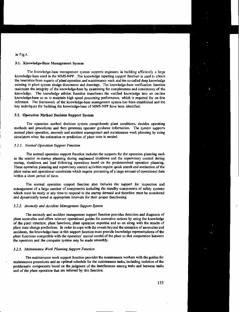
in Fig.4.
3.1. Knowledge-Base Management System
The knowledge-base management system supports engineers in building efficiently a largeknowledge-base used in the MMS-NPP. The knowledge inputting support function is used to obtainthe heuristics from experts of plant operation and maintenance work and the so-called deep knowledgeexisting in plant system design documents and drawings. The knowledge-base verification functionmaintains the integrity of the knowledge-base by examining for completeness and consistency of theknowledge. The knowledge edition function transforms the verified knowledge into an on-lineknowledge-base so as to maintain high speed processing performance, which is required for on-lineinference. The framework of the knowledge-base management system has been established and thekey techniques for building the knowledge-base of MMS-NPP have been identified.
3.2. Operation Method Decision Support System
The operation method decision system comprehends plant conditions, decides operatingmethods and procedures and then generates operator guidance information. The system supportsnormal plant operation, anomaly and accident management and maintenance work planning by usingsimulators when the estimation or prediction of plant state is needed.
3.2.1. Normal Operation Support Function
The normal operation support function includes the supports for the operation planning suchas the reactor re-startup planning during unplanned shutdown and the supervisory control duringstartup, shutdown and load following operations based on the predetermined operation planning.These operation planning and supervisory control activities require quick search and evaluation of theplant status and operational constraints which require processing of a large amount of operational datawithin a shoil period of time.
The normal operation support function also includes the support for inspection andmanagement of a large number of components including the standby components of safety systemswhich must be ready at any time to respond to the startup demand and therefore must be monitoredand dynamically tested at appropriate intervals for their proper functioning.
3.2.2. Anomaly and Accident Management Support System
The anomaly and accident management support function provides detection and diagnosis ofplant anomalies and offers relevant operational guides for corrective actions by using the knowledgeof the plant structure, plant functions, plant operation expertise and so on along with the results ofplant state change predictions. In order to cope with the events beyond the scenarios of anomalies andaccidents, the knowledge-base in this support function must provide knowledge representations of theplant functions compatible with the operators' mental model of the plant so that cooperation betweenthe operators and the computer system may be made smoothly.
3.2.3. Maintenance Work Planning Support Function
The maintenance work support function provides the maintenance workers with the guides formaintenance procedures and an optimal schedule for the maintenance tasks, including isolation of theproblematic components based on the judgment of the interferences among tasks and between tasksand of the plant operation that are inferred by this function.
133

3.3. Intelligent Man-Machine Interface
Design of the man-machine interface or operator interface is very important in thedevelopment of the operator decision aids as a whole because operators can utilize the supportfunctions only through it. The operator support functions may not be utilized properly unless theman-machine interface system is well designed from the human factor view point. The intelligentman-machine interface is designed
(1 ) to accept the operator's requests and to evaluate the operator's focus of attention andthe plant status leading to appropriate information to display, and
(2) to provide the information in easily understandable form by applying multi-mediacommunication,
by using a voice recognition system, CRT units with touch-screens and so on. It includes dialoguemanagement, information edition and presentation functions.
The dialogue management function consists of voice recognition, required inputprocessing and query understanding sub-functions. The voice recognition sub-functions accepts theoperator's voice commands instead of multi-step manual inputs and interprets the sentence structure,context and meaning of discourse to understand the operator's interest. The required input processingsub-function accepts the input requirement through push-buttons and touch-sensitive screens. Thequery understanding sub-function performs the control of smooth dialogue between the man-machineinterface and the operators.
The information edition function decides the information to be presented in accordance withthe plant state and the operator's request history.
The information presentation function provides appropriate information to the operators in aneasily understandable manner using oral and visual presentation.
4. NEW OPERATOR INTERFACE SYSTEM
The technologies developed in the above mentioned development projects are to be introducedgradually into the advanced light water nuclear power plants. They are implemented after carefulverification and validation tests performed using plant dynamics simulators with participation of theveteran operators from utility companies. The design of the operator interface system in the controlroom of the next generation nuclear power plants has been changed to a large extent from theconventional ones by introduction of these new technologies.
As an example, Fig. 5 shows key features of the operator interface system in the control roomof the Advanced BWR [12] to be put into operation in Japan in the latter half of the nineties.
4.1. Operator Interface System and Function
The operator interface system consists of a main control console for the primary operatorcontrol and monitoring functions and an integrated wide display panel to presents an overview of theplant status.
134

4.1.1. Main Control Console
The main control console, from which the total plant is controlled forall phases of operation, includes touch-screen CRTS, flat display devices and a limited number ofswitches as the primary operator interface devices.
The primary means for operator monitoring and control is provided by the seven color-graphicCRTs mounted on the main control console. The CRT displays are driven by the redundant plantprocess computer system. There are many types of formats which can be displayed on the CRTS.These include summary plant status displays, trend plots, system status formats, alarm summaries andoperating procedure guidance functions. Although each CRT is assigned a default display for a givenoperating condition, the operators have the flexibility to select any display on each of the seventouch-screen CRTS. This multi-redundant display capability ensures continued normal plant operationin the event of a failure of one or more of the CRTS.
The system status displays provide information on individual plant systems. The touch-screenson the CRTs provide direct control for nonsafety-related systems at the system component level.
The alarm summary displays support the operator's decision-making process. The presentationof alarms employs optimization techniques designed to suppress nuisance alarms which require nospecific operator action such as the audible alarms associated with the reactor protection system duringthe period of a reactor scram.
The main control console also provides flat displays for extended monitoring and controlcapability. These touch-control flat displays are driven by microprocessor-based controllers which arecompletely independent of the plant process computer system. This diversity of displays and controlsin the console design enables continued plant operation even in the unlikely event of a total loss ofthe redundant process computer system. The flat display devices are used to support both safety andnonsafety system monitoring and control functions.
In addition to the touch-screen CRTs and flat display devices, the main control console isequipped with dedicated hard switches located on the horizontal desk surfaces of the console. Thesededicated switches give faster access and feedback to the operator than the software-driven,touch-screen controls on the CRTs and flat displays.
4.1.2. Wide display panel
The wide display panel, located directly behind the main control console, provides summaryinformation on plant status, critical parameters and key alarms to the operators, supervisors and othertechnical support personnel in the main control room. It includes a fixed mimic display, a variabledisplay, top-level plant alarms and touch-control flat displays. Spatially-dedicated alarm windows forcritical plant-level alarms are also provided on the wide display panel. At the base of the wide displaypanel there are multiple touch-controlled flat display devices for individual system surveillance,monitoring and control. The purpose of the wide display is to provide information on overall plantstatus during all phases of plant operation.
The fixed mimic display, arranged on two adjacent upright panels at the center and right-handsections of the wide display panel, is driven by microprocessor-based controllers which areindependent of the plant process computer system. Information on this panel includes critical plantparameters provided by safety-reîated systems. Specific information displayed on this panel includesthe status of the core c<> 'ling sys:i.-iii, reactor pressure vessel and core parameters, containment and
135

radiation parameters, and the status of safety-related equipment. The information displayed completelysatisfies the requirement for post-accident monitoring without the need for any other displayequipment.
The basic purpose of the variable display, located on the left upright panel of the wide displaypanel, is to provide information on important plant process parameters which supplements theoverview information on the fixed mimic display. The variable display is driven by the plant processcomputer system. Therefore, any display format available on the main control console CRTs can alsobe displayed on the large variable display. Examples of the full color graphic displays that can beshown on the variable display are the various safety parameter display formats which would beselected under plant emergency conditions. The information presented on the large variable displaycan be changed depending on the plant operating condition and the needs of the operators.
The touch-controlled flat displays provides the capability for surveillance of systems andequipment during normal plant operation. In addition, these devices can be used for monitoring andcontrol of plant system during maintenance and refueling outages and also during periods when aportion of main control console may be taken out of service for maintenance. These flat displays aredriven by microprocessor-based controllers which are separate from the plant process computer system.
With the new operator interface system together with the computerized operator support systemand the enhanced plant automation capabilities, the role of the operators will primarily be themonitoring of the status of individual systems and the overall plant and the progress of automationsequences rather than the traditional role of monitoring and controlling individual system equipment.
4.2. System Configuration
The basic configuration of the operator interface system is shown in Fig.6. Multiple levels ofredundancy are incorporated into the system for high availability and to ensure that component failuresor system disturbances will not adversely impact plant operation.
The touch-screen CRTs on the main control console are driven by the redundant processcomputer system. Communication between the process computer and the plant system controllers isprimarily provided by the plant-wide networks for data acquisition and control using fiber-opticmultiplexing system. Separate networks are provided for safety-related and nonsafety related plantsystems. Communications with the process computer are provided exclusively via thenonsafety-related portions of the multiplexing system.
The nonsafety-related, flat displays on the right-side of the main control console are drivenby dedicated controllers which are independent from the process computer. System-level controlswitches on the main control console are connected directly to the system controllers withoutinterfacing with the plant process computer system.
The safety-related operator interface devices on the left-side of the main control consolecommunicates directly with the divisional controllers of the plant protection systems. Four separatedivisions of safety logic and control, including four separate, redundant multiplexing networks, areprovided for absolute assurance of plant safety.
The variable display is driven by the plant process computer system while the fixed mimicdisplay, top-level alarms and flat display devices on the wide display panel are all driven by dedicatedcontrollers which are independent of the plant process computer system, thereby providing additionalredundancy and diversity in the main control room displays and controls.
136

5. CONCLUDING REMARKS
The surprisingly rapid progress of the computer and the related technologies has made itpossible to develop sophisticated technology of operator support system for safer operation of complexnuclear power plants. The activities of developing the COS S and the subsequent MMS-NPP are goodexamples.
However, the introduction of new and sophisticated technologies into nuclear power plantoperation generally takes a long time before their practical application because it requires carefulverification and validation as well as the considerations of not only technical and economic factors butalso human and organizational factors such as the shift of the role of operators in the increasinglyautomated plants.
ACKNOWLEDGEMENT
The author wishes to express his sincere gratitude to Dr. K. Monta of Toshiba Corporation,Drs. T. Kiguchi of Hitachi Ltd. and Dr. Y. Fujita of Mitsubishi Atomic Power Industries, Inc. forproviding reference materials.
REFERENCES
[1] SHINOHARA, Y.; Activities on Computer Application for Nuclear Reactor Operation inJapan—an overview, Int. Topical Meeting on Computer Applications for Nuclear Power PlantOperation and Control, Pasco, USA (1985).
[2] MONTA, К. et al.; A Computerized Operator Support System with a New Man-MachineInterface for BYVR Plant, Paper IAEA-SM-268/l 1, International Symposium on OperationalSafety of Nuclear Power Plants, Marseille (1983).
[3] HIGASHIKAWA, Y. et al.; A Computerized Operator Support System for Boiling WaterReactor Abnormal Conditions, Int. Topical Meeting on Computer Applications for NuclearPower Plant Operation and Control, Pasco, USA (1985).
[4] MONTA, K. et al.; Development of a Computerized Operator Support System for BoilingWater Reactor Power Plants, Int. Topical Meeting on Computer Applications for NuclearPower Plant Operation and Control, Pasco, USA (1985).
[5] OKAMOTO, M. et al.; The Development and Evaluation of Pressurized Water ReactorAdvanced Control Room Concepts in Japan - Part I: Advanced Control Board, ibid.
[6] MASUI, T. et al.; The Development and Evaluation of Pressurized Water Reactor AdvancedControl Room Concepts in Japan - Part II: Computerized Operator Support System, ibid.
[7] ITOH, M. et al.; Artificial Intelligence Applications for Operation and Maintenance -JapaneseIndustry Case-, Artificial Intelligence and Other Innovative Computer Applications in theNuclear Industry, Plenum Press (1988).
137
Fig. 3: Events recorded in an Integrated Plant Management System (Example)
[8] HAYAKAWA, H., et al.; Concepts of Integrated Information and Control System for FutureNuclear Power Plants, IAEA-CN-49/25, Proc. Int. Conf. on Man-Machine Interface in theNuclear Industry, Tokyo, Japan (1988).
[9] MASUI, T. et al.; Advanced Man-Machine System for Nuclear Power Plants, Proc.of the 1stInt. Conf. on Supercomputing in Nuclear Applications (SNA'90), Mito, Japan (1990).
[10] MONTA, К. et al.; Development of Knowledge-Based Decision Support System for NuclearPower Plants Operation and Maintenance, IAEA/OECD Int. Symp. on Balancing Automationand Human Action in Nuclear Power Plants, Munich, FRG (1990).
[11] KATO, K. et al.; Advanced Man-Machine System for Nuclear Power Plants - OperatorSupport Functions and Current Development Status, Reliability Engineering and SystemSafety, 33, Elsevier Science Publishers (1991).
[12] ROSS, M.A. et al.; Control Room Design and Automation in the ABWR, Proc. IEEE NuclearPower System Symp., Arlington, USA (Î990).
138

Stage
1970 1975
I
I960 1985
I
1990
I
T
TMI
Accident
Chernobyl
Accident
Domestication 7/ Improvement t
Standardization 11Advanced LWR
Main Theme
in С с I| Introduction of ] ( Enhancement | [ Ira]
V Technology J Iof Reliability/ I in
mprovement
Monitoring
Enhancement of
Ope. С Mainte.
Support Function
Control Room
Panel (CRPI
Development
Conventional CRP(Domesticated/I-.proved)
New CRP Advanced CRP (under
development)
Integration
of
Information
Use of Color
CRT On-line Core
Monitoring
Advanced
Cabling
TechnicsOptical Data
Transmission
Multi-
ComputerCRT Integrated
Display Г
Optical DataTransmission Network
•Large-scale Display
.Voice Recognition t
Response System
High Reliable
Digital Control
System
Plant
Automation
Digital Control of Main
.Operating FunctionIntegrated Digital
Control Network
Automation of
Startup t Shut-
down
1Extention of Automation
Supporting
System
Normal Operation
Guidance
•COSS: Computerized Operator Support System
•HMS-HPP: Advanced Han-Machine System
for Nuclear Power Plant
Fig.l Development of operator decision aid systems and related technologies.
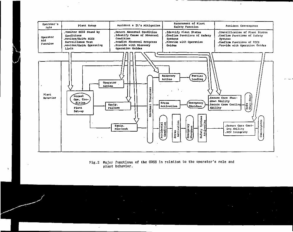
Operator'sRole Fient Setup Accident 6 It's Mitigation
Securcment of Plant
Safety Function Accident Convcracncc
Operator
Aid
Function
.Monitor ECCS Stand by
Conditions
.Monitor/Guide ECCS
Surveillance Test
.Monitor/Guide Operating
Limit
.Detect Abnormal condition
.Identify Cause of AbnormalCondition.Predict Abnormal progress
.Provide with Ricovery
Operation Guides
.Identify Plant Status
.Confirm Functions of safety
Systems
.Provide with Operation
Guides
.Identification of Plane status
.Confirm Functions of Safety
Systems
.Confirm Functions of ECCS
•Provide with Operation Guides
Plant
Behavior
Operator
Action
Equip.
Failure
Recovery
Action
VScram
Activation
.Secure Core Shut-
down Ability
•Secure Core Cooling
Ability
Equip.
Mis-work
- 4
xiСV
•О
•w0uл
-s
сои
•H
•ос0иJ
ииto
с0
•и
л
и«с
.Secure Core Cool-
ing Ability
.PCV Integrity
Fig.2 Major functions of the COSS in relation to the operator's role andplant behavior.

KMS-NPP
Man
Machine
Interface
Qupe
•ator
Operator DecisionSupport
KnowledgeBase
Diagnosis * Guidance
1 COSS
Д
11
SVC
AnticipatedAbnormal State
Plant NormalStat
Plant Process
e
Unanticipated| Abnormal State
MMS-NPP: Advanced Man-Machine System for Nuclear Power Plant
COSS: Computerized Operator Support System
SVC: Supervisory Control System
Fig.3 Operator decision aid systems.
Knowledeeinputtingsupportfunction
/•Operational \I • heuristics \I • Design Il documents.)V «te. J
Advanced man-machine systemfor nuclear power plants
Knowledge base management system
Knowledge..verificationfunction
Plant
IOperation methoddeçision_suD2?11 5Y
Simulator
Intelligentman-machine interface
•Normal operation•Anomalyand accidentmanagement
•Maintenancework planning
Informationedition andpresentationfunction
Dialoguemanagementfunction
/ Operator console\~
C^y ? \J>
KB : Knowledee Base
J
Operator ,
Fig.4 Functional scheme of the MMS-NPP.

Clo**dCircuit TV
VariableDisplay
Wide DisplayPanels
Fixed MimicDisplay
Flat Display(Micro-processorBased)
Main Control 'Console
Hard SwitchPanels
CRT
Key AlarmIndication
Flat Display PlantCommunications
Fig,5 Operator interface system of ABWR.
Variable Display
Flat Displays(Divisional)
Find Mimic DisplayWid« Display Panels
Flat Displays
FUI Display
otvrv
(OMs tonalDisplays
and
Main Control Console
HardSwitchPanels
I Process Computer System
FlatDisplays
Safety System Equipment Non-Safety System Equipment
Fig.6 Configuration of the operator interface system.

COMPUTER-BASED SUPPORT FOROPERATION, MAINTENANCE AND MANAGEMENT
Anders ANDERSSONRinghals, Vattenfall,Viirdbacka, Sweden
Abstract
Computer-Based support for operation, maintenance and management at a nuclear power plant, will inthis report be exemplified by describing the routines at Ringhals Nuclear Power Plant. Ringhals Nuclear PowerPlant on the Swedish west coat, is the largest power station in the country. One of the two government-ownednuclear power plants in Sweden. The plant, with it's tree PWR and one BWR unit, produces approximately 25billion kWh a year, which is 16% of the total electricity production in Sweden.
1. RINGHALS INFORMATION SYSTEM (RIS)
RIS is the administrative computer- based information system developed by Ringhals NuclearPower Plant as a support system for operation, maintenance and management of a nuclear powerstation.
RIS gives support for almost every function at a nuclear power plant. The system is run ona main-frame computer (UNISYS 2200/423). RIS includes all applications on the main-framecomputer. RIS is the general and basic support for everyone.
RIS is a terminal oriented information system. The first functions have been in practical useat Ringhals since 1982. The system has during the years become a more and more complete computersupport.
The 1200 employees at Ringhals continuously use the system from 800 terminals at plant.
1.1. User functions
The main menu showing all subsystem assists those new to RIS. When you have entered(logged in) to RIS you may freely (if you are authorized) move around and directly get informationfrom all administrative routines.
RIS is designed for those not expert at typing. It includes an intelligent use of function keys.
RIS replaces most paper forms. Directly on the terminal you enter your budget, order orrequest of spare parts, request of external order, report a fault, create a work order, request accessauthority for contractors and visitors.
By RIS also most printed lists and reports are replaced Information and reports can besearched and created directly online at your terminal. Most terminals and PC:s have local printers.
1.2. Construction principles
RIS is based on one common database. The different sub-systems are logically linked togetherby e.g. component designations, project numbers, order numbers etc.
143

RIS lias a standardized user-interface. All subsystems are build up by using a few standardscreen-layouts, which are efficient for entering and updating basic data and for searching andpresenting information respectively.The user-demands for new application will always be formed tofit into the standard.
Each type of screen (user function) is created by predefined database structures and programs.A few different solution can be chosen depending on the volume and frequency of updating and onthe data volumes.
Most reports and information can be obtained directly online. Optimized search,files arenormally used for presentation. The files are separated from the database for the basic data. Standardmodules are used to update the search files online or in batch daily or weekly depending on thedemands. In this way the presentation module can be used in the same way for all information,independent of if the basic data is handled in RIS or in a subsystem.
Presentation of information in R1S is structured in two ways:
according to the demands of the basic functionas prepared and aggregated information according to business demands and accordingto the need at different levels within the organization (for low-, mid- and topmanagement).
A common report routine is used for RIS. AH reports can be started by using one onlinefunction. You specify selection conditions, layout, sort order, printer etc. The last example of eachreport is stored in the database as documentation. You may e.g. select a subsystem and by paging getactual examples of all existing reports.
The construction principles make RIS a system designed for handling large data volumes withhigh performance. Standardized screens, programs and database structures in separated modules makefast and simple developing and maintaining R1S applications.
1.3. Function areas
The RIS program is divided into six main information areas: Maintenance, MaterialsAdministration, Finance, Personnel Administration, Executive Information and Specific Nuclear PowerSystems. Each area will briefly be described further on in the report.
To make information more easy to use, the general presentation of information from thedifferent functional computers are also included in RIS.
2. COMPUTER BASED ADMINISTRATIVE SUPPORT AT RINGHALS
2.1. Technical base
A general communication network (Ethernet,TCP/IP) is gradually build up at Ringhals. Itreplace an old star type network. The new net is the base for the actual information structure.
All computers, e.g. process computers, local servers and the administrative maine-framecomputer are connected to the net. By connecting a PC or a UNIX workstation everyone should beable to reach all relevant functions and data.
144
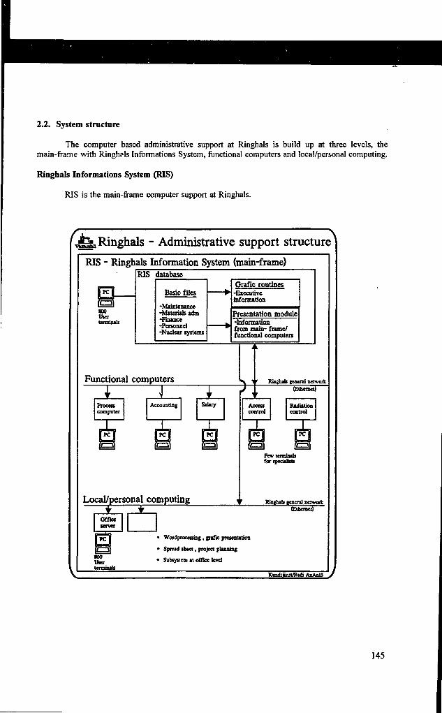
2.2. System structure
The computer based administrative support at Ringhals is build up at three levels, themain-frame with Ringhals Informations System, functional computers and local/personal computing.
Ringhals Informations System (RIS)
RIS is the main-frame computer support at Ringhals.
Ringhals - Administrative support structure
RIS - Ringhals Information System (main-frame)RIS database
Basic files
-Maintenance-Materials adm-Finance-Personnel-Nuclear systems
Cfrafic routines-Executiveinformation
Presentation module-Informationfrom main- frame/functional computers
Functional computers У ' Ringhib general network
Processcomputer
1Accounting Siluy
Local/personal computing
(Ethernet)
Accesscontrol
Radiationcentral
Few termisilsfor tpeciilisu
Knghib general network(Ethernet)
Officeserver
•00tter(елшваЬ
WordproeessiBf, trafic presenution
Spread sbeet, project ptarminj
Subsystem it office level
KandtSnst/Redi ЛаАдЦ
145
,
Functional computers
The main-frame based support is complemented by local computers for specific functions, e.g.process computer, company accounting, salary routines, access control, dosimeter control andevaluation, valve testing etc..
Most of these computers are logically connected to the main-frame applications. Input datafor various applications are created and maintained in RIS.Data for presentation is periodically transferred to RIS.
Normally a limited number of end-users work directly with the systems. General search andpresentation of information is done within RIS.
Local/personal computing
Each group or office have their terminals (PC) connected to a local PC-server. The serversare mostly used for local computing at office and personal level based on standard PC products asword processing, graphic presentation, spread sheets and project planning.
Information searched and presented in RIS can be transferred as input to the different PCproducts. Data transfer from RIS to PC can be controlled by applications or spontaneously.
End-user interface
To make the administrative support more user-friendly, all applications on the differentcomputers are (or will be) run under the WINDOWS user interface.
That means e.g that an end-user can simultaneously run RIS (the maine-frame applications)and different local applications in different windows on his terminal. He can use standard WINDOWSfunctions as cut and paste.
3. MAINTENANCE
3.1 Summary
The RIS maintenance system includes production systems, outage and operation planningsupport, engineering project planning and property maintenance routines. The component data baseforms the foundation of the maintenance system. This contains information for all power stationcomponents (pumps, monitors, ventilation fans, instrumentation, etc.). The component number is thekey to the information. Other maintenance information is tied to the component data base. Onlinethe following information is obtainable via function keys:
Technical documentation(drawings, instructions and handbooks) and administrativedocumentation (maintenance instructions and reports).
Work orders (work-in-progress and reported faults).
146

History (previous controls, observations and faults of respective component).
Preventive maintenance and outage program (contains collected experience regardingthe needs of each component, and current official standards to be met).
Work orders and permits (to carry out work) are created for the annual outage with the helpof the preventive maintenance data and the engineering project data. All work is scheduledautomatically using the outage plan. Requisites for outage in the form of work orders, permits,shut-downs and schedules are printed out.
3.2. Outage planning
We get the real benefits of the different basic data bases when we make use of the integrationbetween the systems. One example is the handling of outages.
During autumn and winter the operation, maintenance and engineering departments preparetheir subsystems for the next outage.
The operation department creates and checks their shutdown areas (isolations, padlocks). Theshutdown areas define how to stop different functional areas for maintenance. In RIS is registeredwhich activities have to be carried out to stop respectively take in operation a shut down area. Foreach area a list of components which can be maintained during a stop is entered.
For each unit there are several hundreds of prepared shutdown areas comprising smaller orbigger areas. The system gives the operators a proposal, which shutdown areas are appropriate to usebased on the actual workload. Maximized maintenance work should be done with minimizedadministration and work for the isolations.
The maintenance departments adjust the outage program within the system for preventivemaintenance (PM). Adjustments are based on experience from last outage, information from otherplants and demands from the authorities.
Planning and modification of workorders and the PM-program can be entered efficiently. Yourequest a selected and sorted list of the wanted activities. By using function keys you get the fieldsyou want to update presented as columns in the list. Then you may do paging and updating of onepage (15 activities) at the same time.
The engineering department creates together with operation and maintenance the program formodifications during next outage. Construction is made for decided projects. AU work supported bythe systems for projects and technical documents. The installation activities relate to the work orderroutines.
147

ЛЕТ.n
R I S OUTAGE
• Planning • Tags• Control • Print-outs
t t
Engineeringprojects
Preventivemaintenance
Shut-downareas
Workorders
/
Materialreservation
request— *
Store/Purchase
V
FUNCTIONS
Outageschedules
P "shut-down
/ ,
Dosimetry ->• Permits
^ -Control
v • Forms
N. Workpermits
Ут Control• Forms
33. Outage work
A month before the outage all workorders will be created from the PM-program and from the
project system for installation activities.
Based on the workload for the outage the system makes a proposal, which shutdown areas areappropriate to use. The operation department schedules the chosen shutdown areas according to themain time schedule for the outage. RIS connects the around 2500 outage workorders to the selectedshutdown areas. The workorders are marked with time for earliest start and latest finished.
The planning of workorders is controlled by help of GANT schemes per maintenance groupor supervisor. Maintenance complements with detailed planning of the workorders. This will be aniteration process. If the resource demand is to high for some jobs, the schedule for the affected areashas to be adjusted. RIS makes the replanning, adjusts the workorders.
When planning has been finished, information is created for the work permits (the permitsfrom the operation to cany out a workorder) and radiation permits. The system prints out forms forworkorder, work permits, radiation permits and detailed instructions (including tags) for the shutdownareas (isolation work).
148

The work permit system makes it possible for operation department to supervise the outage.They can e.g. list jobs online (on the screen) which are current, not started or delayed for chosenmaintenance group, foreman, functional system or shutdown area.
For added activities and after a change of the main outage schedule each maintenance groupwill automatically get a printout of the workorders, which after the change are planned to be doneoutside the new time limits.
3.4. Routines during operation
Planning and decision for maintenance during operation is done at the daily morning meetingat each unit. Meetings with representatives from operation, maintenance, chemistry and radiationdepartments.
Entered and remaining workorders are controlled in RIS. You may online get workorderslisted on the screen in an arbitrary way. You yourself choose the selection, sorting and presentedfields in the list. You can e.g. check the reported workorders for your unit during the last 24 hours.
Preparation of and data entry for workorders can be done directly by changing the actual datain the listings. This as an efficient way of minimizing the data entry work.
4. MATERIALS ADMINISTRATION
4.1. Summary
We hire a large number of contractors (up to 1000/unit during an outage). The store is mostlya security store. The material administration routines have been constructed according to theseassumptions.
Data bases to this system are store articles, orders, invoices a,id financial transactions. Thestore data base contains articles in store, order points and history. The order data base collects allorders for further processing. Article, order and verification numbers are the keys to the information.
One main objective of the subsystem is to make it possible for the purchase department toconcentrate on agreements and large orders.
For store parts the system makes order proposals per supplier according toreservations, estimated consumption and order points. An increasingly largeproportion of order volume can be rationalized due to order proposals realized withinRIS.
The purchase function is partly distributed. Specific users can be authorized to createorders based on the order requests entered in RIS. The authorization is givenindividually with a limited maximum order amount.
The system writes out all order letters. Delivery followup, delivery reporting, invoicing andoutpayments are dealt with using previously obtained information.
149

RIS - Material administration
Order requestft/rdxoe
orderAdoxjw-
ledgemenlsDetvery
Order suggestions!—«"HS order routine J — •Delivery
folow-vip
hvoices
deception &
slorng
Spore part
reservation/
request
Store
routinesStore
hvoidng
routines-Payments-
RIS oaounting I
Centroi
acoount'ng
(externei
computer)
4.2. Logical provision flow
The user initiates an purchase order by enter in RIS a request for a new order. To minimizedata entry work, you may copy parts of former orders.
Request for parts from store are done within RIS. The store system includes search functionsto find spare parts in an easy way. Your searching can be based on your own withdrawals during thelast years or on spare part information.
For consumption parts the system creates order proposals based on order requests And orderpoints in the store. The proposals are based on information from former suppliers, orders, agreementsand calculated consumption prognosis.
For spare parts the persons in charge at maintenance and quality control departments get anonline list of the parts they have to handle. Total information for rebuying is stored in RIS. Theycomplement and adjust the information from last repurchase and approve the rebuying by enteringtheir signature. The approval could be for an individual repurchase or for a specific time period.When both maintenance and quality control department have entered their approval, RIS generates anorder-proposal.
The purchaser checks and approves the proposals. The order letters for approved orders willbe printed out.
After the orders have been sent to the suppliers they will be supervised with help of thedelivery follow-up module. The purchaser enters all notes as information for the users (customers).
The store staff checks the deliveries towards the order information and makes the data entry. RISprints adhesive labels with information and address for distribution to customers or for storage purposes.
The data entry work is minimized. For delivery reporting the system presents not deliveredquantities from that order. The store staff confirms or adjusts the divergences.
150

4.3. Invoice routines
Entered order and delivery information is the base for the invoice module.
RIS handles automatically invoices to small orders. The system controls the invoices and createspayment and accounting transactions based on order information. Significant discrepancies betweendeliveries and done payments will be listed monthly.
The invoice controllers take care of invoices to large orders. They specify order number andthe time interval the invoice refers to. RIS summarizes the deliveries and creates a checked outline forthe invoice. From a correct outline, information for payment and accounting is created. Otherwise thecontroller has all information within the system for further control.
5. FINANCE
5.1. Summary
All financial information and control at Ringhals is done directly by using a RIS-terminal. All
forms and reports on paper have been abolished.
RIS automatically creates transactions for economic activities such as time reports for contractorsand employees, deliveries, store movements and invoices. RIS transfers to and gets appropriateinformation from the Swedish State Power Board central accounting system.
The economic control within Ringhals is result oriented. Each group has to sell their activitiesto other departments. The prizing shall be based on each groups internal costs. An internal invoicingsystem creates automatically the economic transactions based on agreements between 'sellers' and'buyers'.
Each group at lowest level enter their budget and internal agreements.
RIS gives you online functions for budget-, cost- and result follow-up, balance sheets and detailed
cost analyses at all levels.
R I S - FINANCE
Accounting Folowrup
еокCmrd
AccouiNng
Manto) Kudl
R u mMow-up
Economic
151

5.2. Budget
At Riiighals we have one official budget based on production cost and sale of electricalenergy. This budget is complemented by internal budgets. The base for internal invoicing. Eachgroup budget their buying and selling of services and their internal costs. The budget for internalcosts gives the pricing (price/hour) for the group. Key values are price/hour and percentage soldhours.
Each group enters their budget in RIS. The system gives summing up and presentations atall levels.
5.3. Agreements
Agreements between departments at Ringhals are used as a specification for an internalinvoicing function. Agreements for all projects are entered in RIS. For approved agreements (signedin RIS by buyer and seller) RIS creates monthly transactions for invoicing and payments.
For fixed agreements transactions will be created according to a decided payment plan. Forrunning agreements RIS creates transactions based on the turnout.
5.4. Accounting
In order to be able to correlate the turn out to budget the accounting in Ringhals is based onbooking of used resources.
Costs for contractors and materials are booked to order price when we use the resources (dataentry of timereports and deliveries). Eventual differences are booked at payment of the invoices.
Accounting for The Swedish State Power Board (Vattenfall) is done with a central accountingsystem (EPOK), which is run on a computer at the 'head office in Stockholm. All transactions forthe accounting are generated from RIS. Transactions from time reports for employees andcontractors, delivery and withdrawal of material and invoices.
5.5. Economic analysis
At the end of each economic period (around the 20th of each month) information foreconomic analysis is updated in RIS. Transactions are generated from budget and agreements(internal invoicing). The turnout (costs) is fetched from the central accounting. The transactions arecomplemented with information from the basic subsystems in RIS.
The economic analysis is supported by functions at three different levels:
The general view will be given by a set of result reports. The reports can bepresented at all levels of the organization. The economy department designs thereports by using a report generator.
AH totals in the reports can be specified by using the economic analysis module.
The detailed follow-up module gives information for groups and projects down toindividual orders, material requests and time reports for employees and contractors.
152

Fig.l Development of operator decision aia systems anu íeiaitu leun
All information and reports will be created and presented directly (online) with good responsetimes.
6. PERSONNEL ADMINISTRATION
6.1. Summary
We need a safe method of handling and controlling our own staff, visitors and the aroundthousand contractors at site during the outage period.The base of this system is RIS.
RIS includes, except the normal personal information, functions for access supervision,radiation protection, administration of training and health care.
All personnel, contractor or visitor information is looked after by RIS. For each person youcan e.g. get the following information:
Personal data DosimeterSalary information Radiation dosesBasic education (totally) and per taskTraining (history and planned) Car passAccess card Clothes lockerKeys Loan of material
às.
reflex-tin»syslwn
R I S " Personnel administration
Pwsonwl
RJSTraining
odmimtrotiofHtdlh
car*
Parionml dataAcotti
Fkx-lim*nromwtiofi
Statisticsselary data
КОиЮПОЛsyjtcra
UNSrS2200ot КтМсвтвиШиЬммЫКс*
I tc I
Ш«00 Ю-
H t /
6.2. Personnel infornwtkw
The personnel routines are divided between RIS and routines at head office.
153
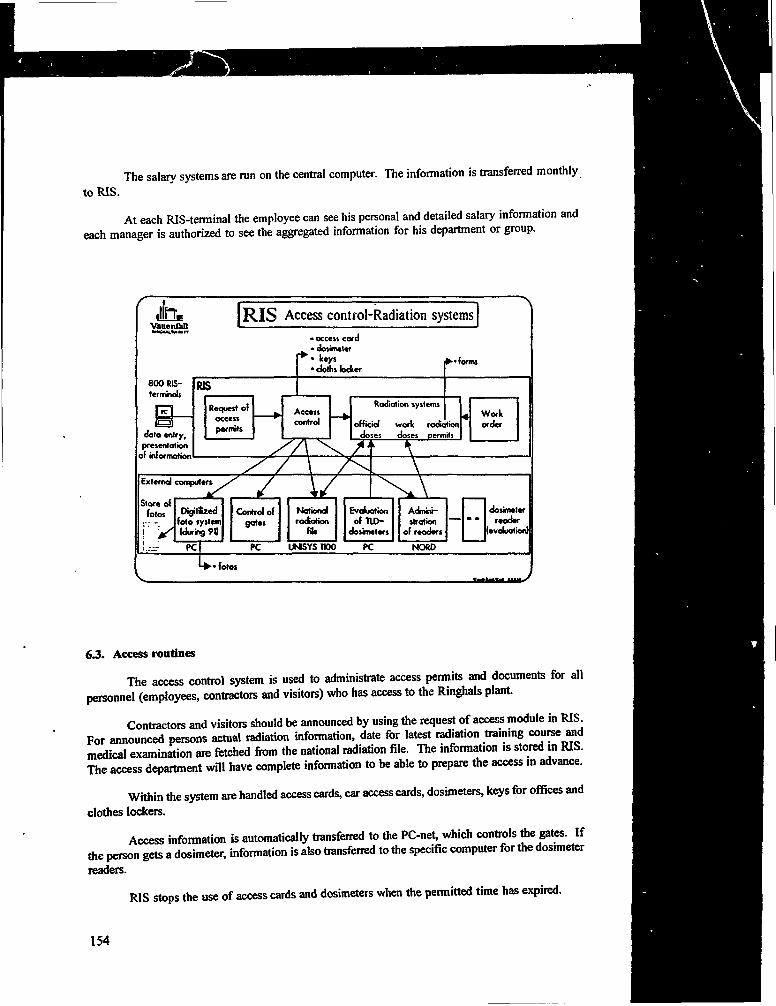
The salary systems are run on the central computer. The information is transferred monthly
to RIS.
At each RIS-terminal the employee can see his personal and detailed salary information andeach manager is authorized to see the aggregated information for his department or group.
iln,VanenfeD.•тммммгт
R I S Access control-Radiation systems
• access corddosimeter
8 0 0 RIS-ter minois
data entry,presentation
if information
Radiation systems
official work radiationdoses doses permits
•(ofmi
PC UMSYSIIOO
Workorder
Nationalrodtotton
He
Evaluationof nO-
dosimeters
Admni-stration
of readers
— • «dosimeter
reader(evaluation]
PC NORD
•fotos
6.3. Access routines
The access control system is used to administrate access permits and documents for all
personnel (employees, contractors and visitors) who has access to the Ringhals plant
Contractors and visitons should be announced by using the request of access module in RISFor announced persons actual radiation information, date for latest radiation training course andmedical examination are fetched from the national radiation file. The information is stored in RIS.The access department will have complete information to be able to prepare the access in advance.
Within the system are handled access cards, car access cards, dosimeters, keys for offices and
clothes lockers.
Access information is automatically transferred to the PC-net, which controls the gates. If
the penson gets a dosimeter, information is also transferred to the specific computer for the dosimeter
readers.
RIS stops the use of access cards and dosimeters when the permitted time has expired.
154
6.4. Radiation system
Through the radiation system in RIS we store and supervise individual and collective dosesat Ringhals. Within the system is administrated the official radiation doses and the doses forindividual jobs (work doses).
The official dosimeters (type TLD) are evaluated each month. The evaluation is done bylocal computers (PC:s). RIS stores the doses and transfers the information to the national radiationfile.
The 'work dosimeters' (type ALNOR) uses special readers for in- and out-passing tocontrolled areas. The readers are connected to RJS through a minicomputer. At outpassing thereceived doses is calculated and presented. The information is continuously transferred to RIS.When a person gets too high dose, RIS gives alarm and stops automatically the access card.
RIS creates statistic information based on the radiation permits.
7. EXECUTIVE INFORMATION SYSTEM
7.1. Summary
RIS executive information system is an easy-to-use presentation function for high qualitygraphs.
The function is automatically included in RIS when you have one of the personal computerswhich we use as terminals for the RIS-system.
The system includes management information at Ringhals and department level. At Ringhalslevel, information is included for control of production, economy, environment,security and personal.The graphs are updated automatically or manually. Manually when the information has to becontrolled and commented upon.
8. NUCLEAR POWER SPECIFICS AND OTHER SYSTEMS
8.1. Summary
Several systems have been collected in this section of RIS. Some of the most important arehandling of waste, fuel administration and different kinds of documentation.
8.2. Waste
Data base for all waste produced at Ringhals. Nuclide content and radiation calculated foreach dispatch. Functions for specification of transport to the national sealed waste store outsideForsmark.
8.3. Fuel administration
The fuel administration system consists of two main functions:
155

Fue! usage and movement accounts (according to IAEA standards),
Generation and check of operation orders for the annual refuelling. The fuel ismoved from the reactor to a fuel basin. Part of the fuel is replaced, after which itis moved back to the reactor according to a redesigned pattern.
8.4. Documentation
In RIS all official documentation is included. RIS has routines for:
Technical documentation (drawings, handbooks ...)
Administrative documents (reports, internal and external letters)Library functions for books and journals (circulation and subscription)Nuclear regulations and standards.Documentation and administration of the communication net for computers and tele.
Documentation of RIS routines and programs.
The documentation routines are combined with text search functions.
156

COMPUTER EMPLOYMENT Ш PROTECTIVEACTION CONTROL SYSTEMS FOR VPBER-600NUCLEAR POWER PLANT
A.B. POBEDONOSTSEVOKBM, Nizhny Novgorod,Russian Federation
Abstract
This paper deals with prerequisites for the technological and economic justification of the use of computersin protective action control systems (PACS). The main approaches to the use of computers in PACS aredescribed as an example of system design a VPBER-600 nuclear power plant. The purpose of PACS in thegeneral structure of reactor plant PCS, is described. The PACS structural diagram is given. The functionsperformed by each PACS module are described in detail.
Modern digital technique extends considerably monitoring and control functions that createsthe prerequisites for wide employment of computers in nuclear power plant (NPP) systems.
Now, the employment of computers in protective action control systems (PACS) is limitedin Russia. Mainly, it is due to deficient reliability of general industrial computer hardware.
At the same time, because of development of advanced nuclear plants for NPPs withenhanced reliability and safely, some new prerequisites for computer employments in PACS hasappeared, able to justify their technological and economic expediencefl]. Such prerequisites are:
inherent safety of reactor plants that is the ability to self-regulation and self-limitationof reactor power in terms of natural feedbacks over the whole range of reactorparameter changes;
the equipment of new reactor plants with built-in self-actuated passive devices, ableto provide irreversible actuation of safety systems by the elementary algorithmsimmediately from regime parameters omitting control channels with electroniccomponents.
But the built-in self-actuated passive devices do not show the adaptability and accuracy,the electric controlling systems can provide.
Therefore the self-actuated devices are employed when the controlling systems with electroniccomponents fail to operate.
Besides the PACS should be feasible to control safety system mechanisms not only ataccident but also during nominal operation especially when preparing to NPP commissioning.
From the other hand there is national standard requirement for automatic controlling anddiagnosing of PACS hardware and software serviceability [2,3].
These prerequisites may be realized through extended precision, algorithm variety and higherintelligence of PACS.
157

It is suggested to consider the main approaches to the employment of computers in PACSsby way of example of such system design for VPBER-600 nuclear power unit with inherent safelyand passive self-actuated devices.
The possibility of computer employment in PACSs is caused both by reactor inherentsafety, passive self- actuated devices and by PACS reliability realized using electronic components.The latter is reached due to usage of highly reliable special computers and structural hardwaredecisions.
Power unit process control system is a decentralized system consisting of several computercomplexes, each being able to realize independently the problems of controlling the correspondingpart of power generation process cycle.
The central computer complex of power unit is intended to coordinate the functioning ofcompute complexes in different operating regimes. Information computer system (1CS) connectsoperator workstations in control rooms and PCS controlling computer complexes.
1CS is a dual local network with connected workstations and peripherals. PCS structuraldiagram is given in Fig. 1.
PACS is a constituent part of PCS firmware complex.
PACS is intended to operate safety system actuating mechanisms when accidents occur andto control their operation. PACS actuates system mechanisms providing reactor emergencyshut-down, emergency heat removal, radioactive media confining in the design boundaries, controlssystem equipment ensuring safely system functioning. It provides also monitoring and control ofabove mentioned mechanisms, when preparing the technological systems to operation (filling withworking medium, etc.) before reactor start-up.
PACS is made by hardware as two independent sets, each capable to provide all safetyfunctions required. Structural diagram of one PACS set is given in Fig.2.
Set hardware and cable communications over the plant site are arranged so that internal orexternal event (fire, air crash.etc.) can not fail simultaneously more than one PACS set.
Each set consists of controlling computer complex, primary information conversion andcommand issue equipments associated with this complex, emergency control panels in main andstand-by control rooms and cable system.
In each set the controlling computer complex is four-channel and the other hardware isthree-channel. Each channel hardware is made as individual devices having separate secondary powersources.
Cable communications between the devices are separated into channel paths. Different PACSsets are diverse. The diversity is attained due to:
different controlling computer complexes sets' development by different designers;different read-only-memory use;fabrication by different vendors;Primary information conversion equipment (PICE) implements;analogous and discrete transducers inquiry;
158

information conversion into digital code;inner diagnostics and self-checking;information transfer to the controlling computer complex;information transfer path diagnostics.
The PICE is made as three-channel one. The channels function independently. When onechannel fails PICE operation is not disturbed as a whole. The PICE is connected with controllingcomputer complex by controllers. When transferring the information the conductive decoupling isprovided. Every PICE channel transfers the information to every controlling computer complexchannel.
The command issue equipment is intended to transfer commands from controlling computercomplex and remote control commands issued by an operator (omitting the controlling computercomplex) to safety system actuating elements (SSAE), such as valves, pumps, etc The command issueequipment ( CIE ) is made as a three-channel one.
The CIE ensures:
reception of automated and functional-group control commands from controllingcomputer complex and remote control commands from operator panel;command conversions into positional code;power gaincontrol command issue to actuating elements (majoritation of CIE channel outputsis provided in cable network),command» passing validity checkhardware and communication link diagnostics. The CIE consists by hardware ofone-channel conventional structural unit sets.
Command issue for reactor trip is realized otherwise.
To control the reactor during normal and emergency regimes the PCS is provided for reactorcontrol and protection system (CPS). To realize reactor emergency protection function according toneutron-physic parameters the system is made as a two-set one with thrice-repeated inner redundancyof each set.
To execute the reactor emergency protection function it is necessary to de-energize CPS drivemotors. Thereby the compensating members drop under gravity and shut down the reactor. Toimplement emergency protection function there is an emergency protection unit (EPU) in each CPSset.
Neutron-physics and heat-engineering parameter signals (from the controlling computercomplex of associated PACS set) and operator commands from main control room and stand-bycontrol room enter the EPU through three channels.
The entering of any command through not less than two channels causes CPS drive powercircuits break in two points and realizes emergency protection function. EPUs are made with logicsrealized by hardware. To ensure two break points in one circuit diverse breakers are used (see Fig.2).
PACS controlling computer complex where logic processing of information is implementedis the main part of the system. The controlling computer complex is fourfold redundant, where each
159

channel is a specialized controlling computer.
The controlling computer complex provides:
obtained information processing by program methods to determine its validity;
logic information processing to reveal the emergency;
command set forming according to protection algorithm required in specificemergency;
realization of prohibitions, priorities, change of setpoints according to controlledobject state and operation mode;
inner self-diagnostics of hardware and software;
reconfiguration of the system and change of output signal processing logic (twoof four) when faults occur;
required information transfer to other PCS subsystems and to the displays ofemergency panels of main control and stand-by control rooms.
The controlling computer complex ensures the possibility of functional test checks.
The programs of protective action realization (algorithms) are invariable what is achieved byfirmware methods and are stored in non-volatile memory in ROM of controlling computer complex.
The controlling computer complex is diagnosed mainly by software, possible faults atdiagnosing are not influencing the capability of controlling computer complex to execute the requiredfunctions for safety system actuation.
PACS controlling computer complex is connected to other PCS subsystems throughfiber-optics communication lines.
Emergency control panels with control members and information displaying means areprovided in main control and stand-by control rooms to display safety information and to controlremotely safety system mechanisms.
Both in main control and stand-by control rooms it is possible to control and to obtaininformation from both PACS sets.
At emergency control panel there are safety display, central signalling system, individualdigital indicators, function keyboard and individual remote control key for especially importantsafety system mechanisms.
Besides, safety information can be represented on normal operation displays, because allrequired information on safety systems is transferred from PACS controlling computer complexes toPCS through power unit controlling computer complex.
The adopted decisions for PACS construction, in addition to natural reactor characteristicspower self-limitation) and self-actuated devices should provide the efficient and safe operation
160

ofVPBER-600NPP.
CONCLUSIONS
1.
2.
3.
Computer applications in inherent safety reactor plant PACS is considered to beexpedient and justified.
The use of computers for diagnostic and auxiliary functions, for organization of informationrepresentation control is justified, because it facilitates operation, reduces the probability ofpersonnel errors, and improves system operation reliability as a whole.
Protective action invariable algorithms with firmware employment and independence ofsafety functions from possible failures, when diagnosing system firmware, improve PACSoperation reliability.
161

MAIN CONTROL ROOMSTANDBY CONTROL ROOM
SYSTEMFOR REACTOR
1. EMERGENCY CONTROL PANEL2. INFORMATION COMPUTER SYSTEM3. CENTRAL COMPUTER COMPLEX OF
POWER UNIT4. CONTROLLING COMPUTER COMPLEX
OF PROTECTIVE ACTION CONTROL5. CONTROLLING COMPUTER COMPLEX
PLANT NORMAL OPERATION SYSTEM6. CONTROLLING COMPUTER COMPLEX OF DIAGNOSTIC
AND CONTROL7. TURBOGENERATOR SYSTEM CONTROLLING COMPUTER8. INSTRUCTION ISSUE EQUIPMENT9. PRIMARY INFOORMATION PROCESSING EQUIPMENT10.SELF-ACTUATED PASSIVE DEVICES
COMPLEX
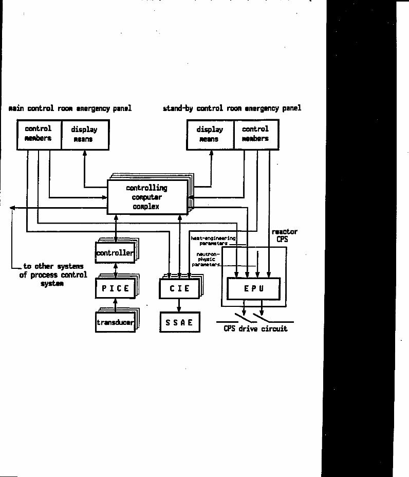
min control rood emergency panel stand-by control roon emergency panel
controlHewers
displaymeans
controllingcomputercomplex
controller
to other systemof process control j m m ^
systenP I C E
i
heat-cnginceringparant tars.
ntutren-physic
paranctars.
C I E1transducer
reactorCPS
EPU
SSf iECPS drive circuit

THE TORNESS AGR DIRECT DIGITAL CONTROL ANDDATA PROCESSING COMPUTER SYSTEM
D. WELBOURNENNC Ltd.,Knutsford, Cheshire,United Kingdom
Abstract
The extensive information and control computer installation a! Torness AGR in Scotland is described.The display and control functions are outlined. Operating experience with the system has shown the successof the co-operation between the utility (SSEB, now SNL) and the suppliers (Ferranti, NNC and DIA Ltd.).
1. INTRODUCTION
The latest Advanced Gas Reactors (AGR) have been constructed at Heysham II in theNorthwest of England and at Torness in the Southeast part of Scotland. The overall design is verysimilar to the successful Hinkley and Hunterston AGR stations, with one exception being the controland instrumentation system and its associated cabling. This change reflected the impact of computerand micro-processor technology on plant protection, control and operator displays.
For the South of Scotland Electricity Board (SSEB), now Scottish Nuclear, a major changein philosophy was the use of direct digital control for the complex task of total plant control. NNCLimited, who were the main nuclear island design and construction agency, had experience with theapplication of DDC on power stations. However, the detailed design proposals were more ambitiousat that time than on any power station or plant process in the world. This approach had, therefore,some risks for Scottish Nuclear due to its limited experience of computer control at that time.
Torness NPS is a twin unit AGR station. Each reactor is rated at 660 MWe. Unit 1 has beensupplying electricity to the national grid since Max 1988 and Unit 2 since February 1989.
This paper discusses the successful Torness computer system, with particular emphasis on theDirect Digital Control (DDC) which was successfully applied. The contents is derived directly fromReferences 1, 2, and 3.
2. HARDWARE AND SOFTWARE SYSTEM SIAVLY
The supply of the Torness Control and Data Acquisition Systems was open to competitivetendering and this resulted in Ferranti Pic being awarded the contract for the supply of the completeunit control system, data acquisition and operating system software but excluding any applicationssoftware.
NNC Limited were awarded the contract to write the applications software based on theirexpertise in writing the applications software for the Hartlepool and Heysham 1 AGR computersystems for display and direct digital control.
The Ferranti Argus hardware system had previously been used on nuclear plant and the
164

processor arrangement offered a number of upgrade options which could be taken up if the initialestimates of processor loading proved to be incorrect.
CORAL was chosen as the computer language because it is block structured, with a longhistory of successful use for high integrity application in lhe UK. The Ferranti ARGUS range ofcomputers also has well proven CORAL development extensions to the standard operations system.
In nuclear power station construction, the supply of equipment, the installation and thesupporting documentation must follow very rigorous and well defined Quality Assurance (QA) path.The SSEB had identified the dangers of incorrect interpretation by programmers of the realrequirements, the difficulties of testing large software systems and the difficulties of monitoring theprogress of software production.
The SSEB's strategy therefore consisted of:
1. Close control of the system design and software development with minimal disturbance tocontractors.
2. Close control QA arrangements.
3. The intention to use the simulator for independent monitoring of software production.
4. Fast resolution of important problems and issues.
The software provided by NNC included that for alarm processing, logs and records, operatorinterface support» standard and special calculations, and reactor management. All plant signals to beprocessed were identified and scheduled by NNC. The NNC strategy for testing relied on aprogressive buildup test coverage, using a joint commissioning team on site led by NNC. Testingincluded:
a) Comprehensive isff-line tests by the contractors.
b) Signal input injection and output monitoring on each target configuration.
c) Staged commissioning tests which integrated the plant with the computer systems.
The difficulties in achieving software production targets were identified early in the projectand a number of packages were subcontracted by NNC to Digital Applications International Ltd.(DAI Ltd.). The form of the detailed design and test documents produced by NNC made it relativelystraightforward to split the software production and tests between DAI and NNC.
DAI were also engaged to assist NNC in the software systems building and testing. Althoughthe control system is distributed, communication can only occur if all the software in each node iscorrectly linked together in a Super system build. With no software changes allowed on site, acomplete build was required for each software change identified by the site team. Executedmanually, this build process was error prone and could take a number of weeks. Total automationof the offline test and build processes enabled modified software to undergo a precise repeat of itsoriginal test and build route, with a guaranteed delivery date of the verified software to the site team:A rebuild turnaround of less than one week was achieved using the off-line service systems. Withover 20 rebuilds necessary before "raise power," these techniques were of crucial importance bothin time scale and QA terms.
165

3. INSTRUMENTATION AND CONTROL SYSTEM OVERVIEW
At Torness Power Station, the amount of normal instrumentation within the Central ControlRoom (CCR) is limited to that which is necessary to allow continuous operation at steady load fora short period in the event of a catastrophic failure of the Data Processor (DP). The operatorinterface must therefore be comprehensive, accurate and flexible. This is achieved by a customdesigned set of VDU formats complemented by a small number of operator configurable formats.
The Tomess on-line computer system provides the primary method of instrumentationpresentation and data processing for the operators and provides full DDC of all control functionsneeded for operation at powers between 30% and 105% of full design output.
The computer system consists of a network of computer nodes, based on the Ferranti Argus700 range of computers, assigned to each reactor unit, except where common station facilities arerequired. For each reactor unit, the computer system provides both data processing and automaticcontrol functions. For essential data capture, control and display to the CCR operators, the processorhardware is duplicated. These are termed Level 1 systems and are shown in Figures 1 and 2. Singleprocessor systems which collect data not considered essential for continued unit operation are termedLevel 2 systems. Figure 3 illustrates the Level 2 computer system for both units.
Torness NPS probably has the most complex computer configuration of any operating nuclearpower station. The auto control "supersystem" consists of, per reactor, ten input multiplexingcomputers ("muxes"), eleven control computers (CCO1, CCO2 to CCI 1) and a dual online/ standbysupervisory computer ("CS"). Each of these computers is a node in the hierarchical controlsupersystem shown schematically in Figure 2.
4. OPERATOR INTERFACE DESCRIPTION
The MNI (Man-Machine Interface) in the CCR at Tomess consists of an extensive set ofVDUs for format displays, joysticks, keyboards and a graphics printer. The distributed databasecontains approximately 40,000 data points and is maintained throughout the network by autonomoustranscription via proprietary communications software.
In the event of total failure of System DBT, connection of CCR display controllers directlyto Systems A, D, CS allows plant monitoring to continue. A simplified subset of formats is used forthis purpose.
4.1 VDU Formats
Approximately 320 complex VDU formats are grouped functionally as follows:
Plant mimic formats grouped into 26 plant systems. Access to, between and withineach plant system is predefined and implemented by "soft keys" on each format.
Engineering formats again grouped into plant systems. These simple tabular formatswere automatically generated off line from the current database and were usedextensively during the early stages of plant commissioning.
Help formats to assist the operator in using the operator interface. Maximum use of
166

references to operation and maintenance manuals is made.
Operator variable formats. Three types are available: a range of trend formats wherethe operator can enter up to 7 database parameters per trend; a range of tabulardisplays where the operator can similarly select database entries and the currentvalues only are displayed; operator variable logs where the operator can specifycontent, duration and sample frequency for up to 8 logs with 32 parameters per log.
Alarm support formats. Two types of alarm formats inform the operator of the plantcondition: All alarm lists and plant system alarm lists where the operator processesalarms; Unit and plant system alarm mimics where quantitative information ispresented, but alarm processing is not permitted.
Logging and recording support formats. These formats are used to gain access tologging activity information, freeze trends for subsequent analysis, recall historicaldata for on-fine display, and send results to the graphics printer for subsequentanalysis.
4.2. Hardware Interface
The operator communicates with the computer system via System DBT using joysticks andcustom designed keyboards. Function keys are allocated to specific activities, e.g. "accept alarms,"and are complemented by the standard "QWERTY" key pad layout.
In addition, the operator is also able to insert trims into control loops using a combinationof the Computer Input Panel (CIP), and a predefined set of VDU formats. The software supportingthe CIP ensures that the appropriate format is on display before a new trim is inserted into the controlalgorithm.
5. THE AUTO CONTROL SUPERSYSTEM
The muxes and CCs do not have any disc storage capacity - all software and operational datais held in volatile random access memory (RAM). The mux and CC software is thereforedownloaded from CS (via a CC in the case of a mux). There is battery backup on the muxes andCCs in the event of a power failure.
CCO2 to CC 11 and CS are multiprocessor machines, containing more than one processor.Several programs run concurrently by time slicing on one processor. Programs can also run onseparate processors in parallel.
There are analog and digital inputs to the control supersystem but all outputs are digital, ordriven for a precise time by the control software. Most control room pushbuttons and thumbwheelsare connected to the muxes, but a few are connected directly to CS for the amendment of controltrims in the CCS.
The muxes and CCOI, which do not have a mux. together have approximately 1600 analoginputs and 1100 digital inputs. The CCs together have approximately 640 digital outputs. There areno terminal or printer operator interfaces to a mux or CC, which are simply connected directly to ahigher machine in the hierarchy via a serial communications link (HDLC). CS has hard copy
167
,

consoles, alphanumeric VDUS, color graphies VDUs and a thumbwheel input panel to allow autocontrol trims to be adjusted in the CCs, the values being transmitted to the CCs along the serial links.In addition to the inputs panel, system software enables operators to inspect variables or modifycontrol constants in the CCs from CS. CS is also used to process and report alarms and eventmessages generated throughout the control supersystem.
The auto control applications software is divided into several programs, each using separatelycoded and tested standard modules and libraries.
6. MODULATING CONTROL SYSTEM
The overall automatic control combines operation of control systems for five distinct plantareas:
1. The regulation of the reactor heat rate using uniformly distributed regulating rods.
2. The regulation of the mass flow rate of the coolant gas.
3. The regulation of total feedwater flow.
4. The regulation of feedwater flow to individual boiler (or half units) to correct asymmetrictemperature profiles created by onload refuelling.
5. The regulation of the setpoint of the turbine speed governor-
The reactor heat rate (Item 1 above) is a separate, clearly defined system: the reactor isdivided into zones, the reactivity of each zone being regulated by a single control rod. The measuredvariable for the control of a zone is derived from the coolant gas temperatures at the outlets of thefuel channels.
The effects of the control systems are highly interactive because all affect the transfer of heatfrom coolant gas to water/steam in the boilers. Because of this interaction, there are two options forregulating the transfer of heat from the fuel to the water/steam. Either,
(a) the gas mass flow is "forced" and the feedwater flow is under closed loop control tomaintain the desired boiler heat transfer, or
(b) the feedwater flow is "forced" and the gas mass flow is under closed loop control.
Because of the once-through boilers, the pressure of the steam leaving the boilers is verysensitive both to the response of the turbine speed governor to frequency fluctuations and to changesin feed pressure. It is necessary, therefore, to maintain the steam pressure within close limits. Again,two options for automatic control:
(i) The steam pressure can be controlled by regulating the setpoint of the speedgovernor. A consequence of adopting this option is that load variations initiated bythe speed governor are removed by the steam pressure control action. With thisconfiguration, the load generated is regulated by "forcing" the heat rate of the steamsupply, employing option (a) or option (b) above.
168
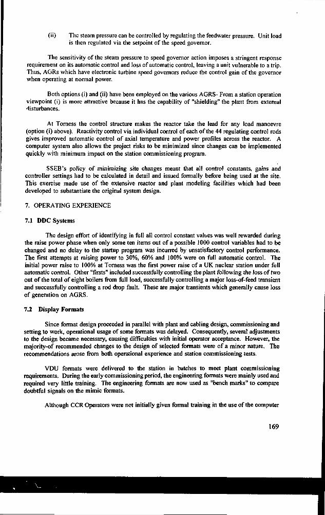
(ii) The steam pressure can be controlled by regulating the feedwater pressure. Unit loadis then regulated via the setpoint of the speed governor.
The sensitivity of the steam pressure to speed governor action imposes a stringent responserequirement on its automatic control and loss of automatic control, leaving a unit vulnerable to a trip.Thus, AGRs which have electronic turbine speed governors reduce the control gain of the governorwhen operating at normal power.
Both options (i) and (ii) have been employed on the various AGRS- From a station operationviewpoint (i) is more attractive because it has the capability of "shielding" the plant from externaldisturbances.
At Torness the control structure makes the reactor take the lead for any load manoevre(option (i) above). Reactivity control via individual control of each of the 44 regulating control rodsgives improved automatic control of axial temperature and power profiles across the reactor. Acomputer system also allows the project risks to be minimized since changes can be implementedquickly with minimum impact on the station commissioning program.
SSEB's policy of minimizing site changes meant that all control constants, gains andcontroller settings had to be calculated in detail and issued formally before being used at the site.This exercise made use of the extensive reactor and plant modeling facilities which had beendeveloped to substantiate the original system design.
7. OPERATING EXPERIENCE
7.1 DDC Systems
The design effort of identifying in full all control constant values was well rewarded duringthe raise power phase when only some ten items out of a possible 1000 control variables had to bechanged and no delay to the startup program was incurred by unsatisfactory control performance.The first attempts at raising power to 30%, 60% and 100% were on full automatic control. Theinitial power raise to 100% at Torness was the first power raise of a UK nuclear station under fullautomatic control. Other "firsts" included successfully controlling the plant following the loss of twoout of the total of eight boilers from full load, successfully controlling a major loss-of-feed transientand successfully controlling a rod drop fault. These are major transients which generally cause lossof generation on AGRS.
7.2 Display Formats
Since format design proceeded in parallel with plant and cabling design, commissioning andsetting to work, operational usage of some formats was delayed. Consequently, several adjustmentsto the design became necessary, causing difficulties with initial operator acceptance. However, themajority-of recommended changes to the design of selected formats were of a minor nature. Therecommendations arose from both operational experience and station commissioning tests.
VDU formats were delivered to the station in batches to meet plant commissioningrequirements. During the early commissioning period, the engineering formats were mainly used andrequired very little training. The engineering formats are now used as "bench marks" to comparedoubtful signals on the mimic formats.
Although CCR Opeiators were not initially given formal training in the use of the computer
169
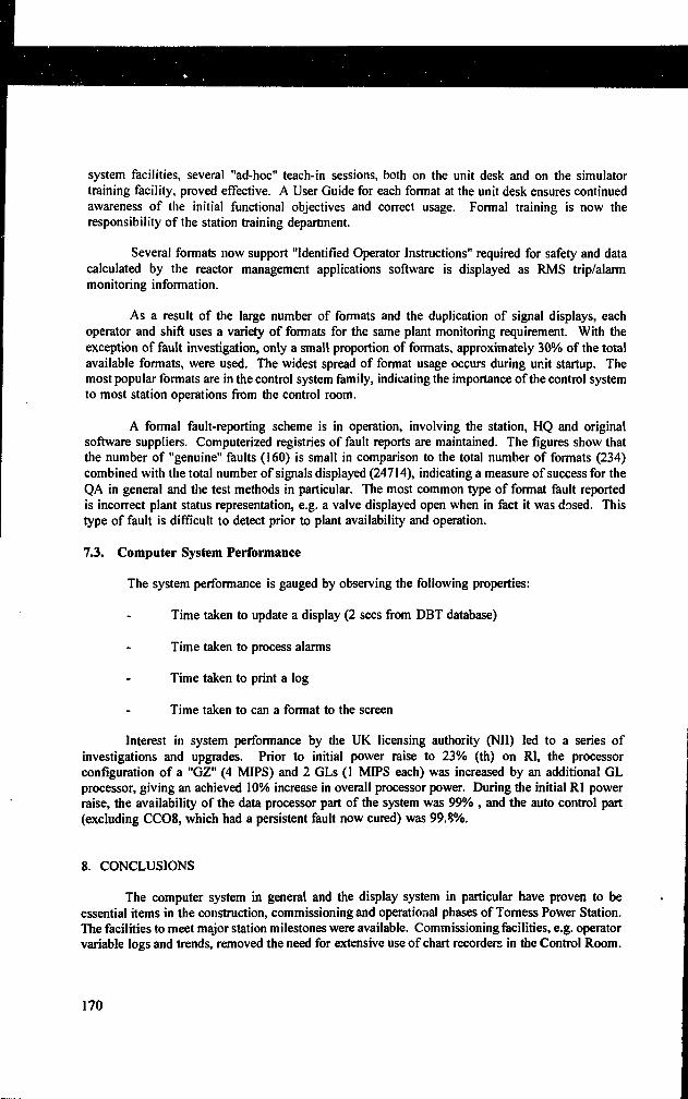
system facilities, several "ad-hoc" teach-in sessions, both on the unit desk and on the simulatortraining facility, proved effective. A User Guide for each format at the unit desk ensures continuedawareness of the initial functional objectives and correct usage. Formal training is now theresponsibility of the station training department.
Several formats now support "Identified Operator Instructions" required for safety and datacalculated by the reactor management applications software is displayed as RMS trip/alarmmonitoring information.
As a result of the large number of formats and the duplication of signal displays, eachoperator and shift uses a variety of formats for the same plant monitoring requirement. With theexception of fault investigation, only a small proportion of formats, approximately 30% of the totalavailable formats, were used. The widest spread of format usage occurs during unit startup. Themost popular formats are in the control system family, indicating the importance of the control systemto most station operations from the control room.
A formal fault-reporting scheme is in operation, involving the station, HQ and originalsoftware suppliers. Computerized registries of fault reports are maintained. The figures show thatthe number of "genuine" faults (160) is small in comparison to the total number of formats (234)combined with the total number of signals displayed (24714), indicating a measure of success for theQA in general and the test methods in particular. The most common type of format fault reportedis incorrect plant status representation, e.g. a valve displayed open when in fact it was dosed. Thistype of fault is difficult to detect prior to plant availability and operation.
7.3. Computer System Performance
The system performance is gauged by observing the following properties:
Time taken to update a display (2 sees from DBT database)
Time taken to process alarms
Time taken to print a log
Time taken to can a format to the screen
Interest in system performance by the UK licensing authority (Nil) led to a series ofinvestigations and upgrades. Prior to initial power raise to 23% (th) on Rl, the processorconfiguration of a "GZ" (4 MIPS) and 2 GLs (1 MIPS each) was increased by an additional GLprocessor, giving an achieved 10% increase in overall processor power. During the initial Rl powerraise, the availability of the data processor part of the system was 99% , and the auto control part(excluding CCO8, which had a persistent fault now cured) was 99,8%.
8. CONCLUSIONS
The computer system in general and the display system in particular have proven to beessential items in the construction, commissioning and operational phases of Tomess Power Station.The facilities to meet major station milestones were available. Commissioning facilities, e.g. operatorvariable logs and trends, removed the need for extensive use of chart recorders in the Control Room.
170

Although the display system was selected to reduce the amount of information -shown to theoperator in a "nondestructive" manner, relatively little use has been made of the zoom, pan anddeclutter facilities.
With the exception of fault investigation, only a relatively small proportion of the VDUformats are used. Furthermore, a steady-state plant monitoring, which is the normal operating mode,an even smaller proportion, approximately 3% of the total is required.
In future applications, the CCR operator interface requirements should be established as earlyas possible to allow the computer system design to be frozen early.
The contractors (Ferranti, NNC, Digital Applications International Ltd.) and the SSEBcollaborated throughout the contracts and station construction period to produce a highly successfuland reliable hardware and software system on which the total station operation depends.
Once commissioned, the Torness auto control system has exceeded all expectations since,historically, automatic control has been commissioned in a piecemeal fashion and has required muchmodification, refinement and optimization. The Torness computer system has performed well sinceits initial use and is a credit to all contractors associated with it.
REFERENCES
[1] Automated testing and building of the Auto Control Software for Torness NPS, HILL, W.J.and MITSON, N.M., Digital Applications International Ltd.,Institution of Nuclear EngineersConference, Glasgow, May 1990 (Paper 3:2).
[2] "The Development, Installation and Commissioning of the Digital Automatic Control Systemat Tomess and Heysham 2 Power Stations", CLOUGHLEY, C.K., CLINCH, D.A.L.,Institution of Nuclear Engineers Conference, Glasgow, May 1990, (Paper 3:1)
[3] "Operator Interfaces for Torness on-line computer system" OVERSBY,K., Institution ofNuclear Engineers Conference, Glasgow, May 1990 (Paper 2:8).
171

Dual System Afor analogueprocessingand logging
J ( Backing ЛI у store J
Dual System Dtor digital
processingand alarm handling
T
JJ Local data HI amendment facilities {_I during construction ГI period only J
Controlterminal
Data amendment panel
(change facilityfor alarms, etc.)
Dual System DBTMaintains full data
base and deals withspecial display and
record outputs Tosystem
CS
Tosystem
CS
Zis4iirj>t Л I ч ! Л Г%#«4«%

1SystemDBT
Controlroom signais
L
Reactorcontrol I CC01
computers
Dual System CScoordinates control
functions andassociated displays
Г"I
Sensors of Iactuators I
I Reactor
|
Controlloop
demands
Figure 2. Level 1 Automatic Control Systems

Digitals
Plant investigationand commissioning
system
pill
Waler treatmentplantcontrol room
Colour Д1 Reactor gassemigraphic II Analysis lab
display J\ Radiocnemical lab
Turbine НаИ Chemical Monitoring Room
Backingstore
Controlterminal
Local alarmMonitoring
sysiem
Backing Л | —store J I ,
1
Controlterminal
Reactor vesselstructural
temperaturemonitoring system
11
1 Strain gauge| logger
— 1
L.
Controlterminal
Í Display 1
I semigraphic I

ENHANCED FUNCTIONS OF PROCESS COMPUTERSYSTEMS FOR NUCLEAR POWER PLANTS
BLAKE SINGERScience Applications International Corporation,Marietta, Georgia, USA
SIDDHARTH BHATTBILL K.-H. SUNNuclear Power Division,Electric Power Research Institute,Palo Alto, California, USA
Abstract
The plant process computer system is a system of computer hardware and software that is integratedto acquire large amounts of plant data on a real-time basis. The purpose is to perform calculations which willprovide plant operators with critical operating parameters in normal and emergency situations. There have beennumerous efforts in nuclear power plants around the world to upgrade or replace plant process computers withenhanced functions. This paper describes the system operation and performance of process computers, theirfunctionalities and communications, and their enhanced functions in software and hardware. A prudentapproach to upgrade process computers with enhanced functions can help utilities address obsolescenceproblems, support improved fuel design, reduce operation and maintenance cost, and increase plant and peopleproductivity. In addition, it provides a framework for plant-wide monitoring to support future instrumentationand control upgrades.
1. INTRODUCTION
The plant process computer system (PPCS) provides the plant operators with critical operatingparameters in normal and emergency situations. This is a system of computer hardware and softwarethat are integrated together to acquire large amounts of plant data on a real time basis for the purposeof performing calculations and other functions like scan, log, and alarm, data archival and retrievalon a Central Processing Unit (CPU), and displaying data processing results through the system's ManMachine Interface (MMI). The real time data is gathered from field sensors located throughout theplant. Figure 1 depicts an overview of the PPCS basic functions and Figure 2 shows a typicalconfiguration of a PPC^.
In recent years, there have been efforts in nuclear power plants around the world to upgradeor replace plant process computers. The replacement or upgrade of the PPCS is a complexprocurement activity for the utility which involves several functional groups within the utility (e.g.,Purchasing, Engineering, Operations, Training, Computer Maintenance, Instrumentation & Control,etc.), and several suppliers to the utility (e.g., computer hardware, applications software, andengineering support services, etc.).
Because the PPCS is a significant element in the nuclear plant's technology, its upgrade isjustified through its contribution to the plant's overall performance and operational point of view.Consideration of performance issues focuses upon the reduction in the number and length ofunscheduled outages, and the increase in time between outages due to the acquisition of better and
175

more reliable data about the plant's operations. Modern PPCS has the capacity to integrate theinformation processed by various existing plant computer systems. The following are needs whichmotivate utilities worldwide to upgrade or replace their old PPCS:
Aging of computer system with resulting increases in maintenance costs
Limitations for utilizing current software or adding new software applications
New data sensors added to the plant that cannot be monitored by the existing PPCS
Access to actual plant data necessary to analyze unusual events and trips such thatplant engineers can determine, timely, the effects of these events.
Plant data archival and retrieval to support performance analysis (i.e., fuelperformance with actual plant operation data), and trouble shooting during plantstartup.
Data acquisition, storage and trending functionality to benefit the efforts ofmaintenance, performance, and technical support engineering groups.
Real time plant data for emergency exercises
A system that enhances operator actions and responses to upsets when working underEmergency Operating Procedures (EOP).
2. SYSTEM OPERATION AND PERFORMANCE
System operation and performance requirements for PPCS should be specified functionallyin terms of reliability and response times.
Reliability is expressed as the minimum acceptable percentage of time that the system isoperational, and typically ranges from 99.0 to 99.9 percent. The ability of the system to meet thisrequirement will be primarily constrained by the mean time between failure of and mean time torepair the system hardware configuration. The required level of availability will dictate the hardwareconfiguration in terms of whether a single highly reliable system or two less reliable redundantsystems are required; and will have a major impact upon system cost. At the current state-of-theart,a redundant configuration is required for availability at or above 99.8 percent.
Response times are expressed in terms of the system's ability to sample the plantinstrumentation and generate displays on the graphic terminals. Typical sample requirements for fieldinputs are once per one millisecond for sequence of events field inputs and once per 10 millisecondsfor analog and contact field inputs. Response times for displays can be specified in terms of theamount of time it takes from when the operator requests a display until the time that the displaybegins, or until all information is displayed, or both. The utility must also decide if this minimumtime isto be location-dependent, for example, displays requested from terminals located in the controlroom versus the emergency operating facility. The utility must also decide if, in addition to thisrequirement, a minimum time should be specified between updating the data on the graphic displayterminals. Values for bringing up displays range from 0.S to 5.0 seconds, depending on the locationand type of display; for example, historical and current value displays. Values for updating rates varyfrom one to five seconds. Some additional response time requirements worth considering are
176

specifying the time between request and output of spooled files to the printer devices, and the timerequired to bring the computer system back on line due to non-hardware failures.
Seismic and environmental operational requirements also need to be considered. The portionof the computer system to be located in the control room, e.g., display terminals and printer devices,must be designed to withstand the vertical and horizontal forces at the design basis safe shutdownearthquake. In addition, the range of expected temperature and humidity conditions over which thecomputer system is required to operate uninterruptedly needs to be specified.
3. SOFTWARE FUNCTIONALITY
The functionality of the software is specified at both the operating system level andapplications level. The operating system software requirements define the environment necessary tosupport the applications software and handle the peripheral hardware devices. The applicationssoftware functionality defines how data from the plant instrumentation is collected, processed anddisplayed to the user.
The system software is usually the latest version of the operating system provided with thecentral processing unit(s) as obtained from the hardware vendor. It has operating and diagnosticcapabilities that support a multi-user, multi-tasking environment and communication, with input andoutput devices such as disk drives, tape drives, and printers, as well as other plant computer systems.
The applications software can be categorized broadly into the scan, log, and alarm, plantmonitoring and performaifce, and man-machine interface (MM1) functions. The scan, log and alarmfunction serves to sample the plant instrumentation inputs and log each current value into thedatabase. This process includes converting the incoming signal to an appropriate engineering unitand then checking this value against-various alarm limits to determine if the signal is valid and if itwarrants further attention. In addition, data is selectively archived for subsequent retrieval to supportengineering analysis of historical events. The plant monitoring and performance functions thenprocess the database information to support operational monitoring and performance requirements.The MMI provides the interface to the system for controlling these functions as well as to accessinformation from them. The relationship of these functions is illustrated in Figure 3.
Some base-line scan, log, alarm and MMI functions are common to both boiling water reactor(BWR) and pressurized water reactor (PWR) computer systems. The requirements for the plantmonitoring and performance functions, however, differ considerably between BWRsand PWRsdueto the different way in which power is controlled. Power changes in a PWR are typically performedin a core-wide manner by moving groups of control rods, whereas power changes in a BWR areperformed more locally within the core by moving individual control rods. This requires that theBWR process computer system contain nodal reactor core fuel monitoring functions and the abilityto collect local core data to support off-line detailed calculations. Consequently, PWR processcomputer systems generally include more functions to support overall system monitoring andperformance calculations and BWR process computer systems generally include more functions tosupport reactor core monitoring.
The general software functions for BWR and PWR applications are listed in Table 1.
177
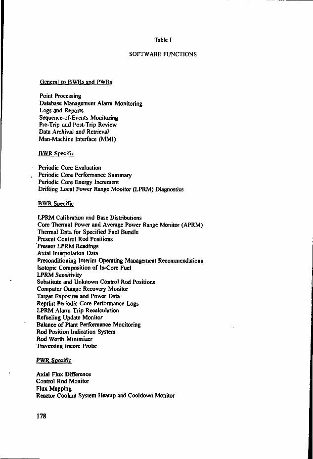
Table I
SOFTWARE FUNCTIONS
General to BWRs and PWRs
Point ProcessingDatabase Management Alarm MonitoringLogs and ReportsSequence-of-Events MonitoringPre-Trip and Post-Trip ReviewData Archival and RetrievalMan-Machine Interface (MMI)
BWR Specific
Periodic Core EvaluationPeriodic Core Performance SummaryPeriodic Core Energy IncrementDrifting Local Power Range Monitor (LPRM) Diagnostics
BWR Specific
LPRM Calibration and Base DistributionsCore Thermal Power and Average Power Range Monitor (APRM)Thermal Data for Specified Fuel BundlePresent Control Rod PositionsPresent LPRM ReadingsAxial Interpolation DataPreconditioning Interim Operating Management RecommendationsIsotopic Composition of In-Core FuelLPRM SensitivitySubstitute and Unknown Control Rod PositionsComputer Outage Recovery MonitorTarget Exposure and Power DataReprint Periodic Core Performance LogsLPRM Alarm Trip RecalculationRefueling Update MonitorBalance of Plant Performance MonitoringRod Position Indication SystemRod Worth MinimizerTraversing Incore Probe
PWR Specific
Axial Flux DifférenceControl Rod MonitorFlux MappingReactor Coolant System Heatup and Cooldown Monitor
178

Incore Thermocouple MonitorSetpoint SupervisionPrimary Plant Performance MonitorBalance of Plant Performance MonitorOperation of Circulating Water SystemSpecial Logs and ReportsPost Trip ReviewLarge Motor MonitorContinuous Calorimetric MonitorThermal Power MonitorReactor Coolant System Leakage MonitorGenerator Winding Temperature MonitorDigital Reactivity MeterAutomatic Plant Mode ChangeFlow CorrectionsSteam Tables
179

4. HARDWARE FUNCTIONALITY
The hardware functionality describes the minimum hardware requirements necessary tosupport the applications software and system performance requirements. The basic system is typicallycomprised of the following general hardware and configured as illustrated in Figure 4:
Data Acquisition Unit(s)
Central Processing Unit(s)
Data Storage Devices
Peripherals
Communication Links
Power Supplies
Unless a specific hardware solution and/or configuration is desired, the hardware functionalrequirements should be general to allow the system integrator the freedom to select a configurationutilizing a standard design that meets the system operation and performance requirements. Forexample, the system availability requirements could be met with a single highly reliable hardwareconfiguration which can typically satisfy a 99.0 to 99.5% availability requirement by having a largemean time between failures. Alternatively, the availability requirements can also be met with aredundant hardware configuration which can typically satisfy up to 99.9% availability requirement.It is important to weigh the cost and benefit of each solution when the final configuration is selected.For example, while a single hardware system costs less, it is subject to single failures that couldrender it unavailable to the plant. On the other hand, a redundant hardware system, where oneportion is in standby and ready to take over should the other portion fail to meet present operatingand performance criteria, provides a system with a higher overall availability as well as a secondarysystem for developing and, to some extent, testing of new or modified applications software.
An example redundant configuration for the general system hardware is illustrated in FigureS. This particular configuration employs redundant data acquisition units which feed two redundantcentral processor units (CPUs). Each CPU has its own system disk and tape drive unit forofT-loading data, but sli.ires redundant dalii disks. The CPUs also serve a common set of graphicdisplay terminals.
5. COMMUNICATION LINKS
The minimum number and type of communication ports to support the peripherals and othercomputer systems are specified in terms of interface type and baud rate. Typical baud rates forperipheral communication range from 3CK» to 38,400. Many standard interfaces are available suchas RS-232. If communication ~vith off--.l.e devices is required, such as those located at the corporateoffice, then the need for modems should be addressed.
Networking both within the PPCS framework and between the PPCS and other plantcomputer fysîc<ns can be accomplished using Local Area Network (LAN) technology. A LAN offershigh-speed communications channels for connecting information and processing equipment. It isideal for connecting together equipment located remotely from the computer room; for example. Data
180

Acquisition. Control Room, Technical Support Center, and Emergency Operating Facility.
It is also well suited for networking with other plant computer systems such as those listedin the following:
Safety Parameter Display System
Plant Simulator
Meteorological Information Data Acquisition System
Personal Radittion Information System Monitoring (PRISM)
Effluent Monitoring System
Equipment Tag Out System
Personnel badging INformation Data EXchange (INDEX)
The LAN is typically composed of coaxial, fiber optic and twisted pair cables due to theirvarying cost and capability'. Fiber optic cable is the most expensive but offers the broadest bandwith,that is, it can transmit the most data at the highest speed. Fibe- optic cable is, therefore, typicallyused to connect the data acquisition hardware to the host CPU due to the large amount of datacollected and the high collection frequency. Coaxial cable costs less than fiber optic cable and haslower, but still substantial bandwith. Coaxial cable, therefore, is typically used to connect nodes(equipment in same location) to the network due to their typically being located a long distance fromthe computer room. Coaxial cable is also normally used to network the PPCS to other plant systems.Where a significant distance exists between the computer room and other equipment areas, a LANbridge is placed in line with the coaxial cable to boost the signals. Twisted-pair cable is significantlyless expensive than coaxial cable but it has a verify limited bandwith. It is, therefore, more suitablefor connecting peripherals with a single location. A single twisted cable is limited to about eightperipherals. An example of usir<g these communication links is illustrated in Figure 6.
6. FUTURE FUNCTIONALITY ENHANCEMENT
Computer technology has been advancing rapidly. There are areas where hardware andsoftware technology improvements are considered beneficial to the nuclear industry. The followingare activities underway within the industry' to produce these improvements to the plant processcomputer system.
6.1 Software
Future software will likely contain the following attributes:
Data structures will become more object oriented.
Information to the control room will become more hierarchical in nature withminimal raw process data immediately presented.
The concept of scan classes (10 msec, lOOmsec, 1 sec, etc.) will disappear as data
181

acquisition capabilities exceed the rate of the field inputs.
Modeling of data objects will allow design changes to be observed and documentedas they occur.
Computer Aided Software Engineering (CASE) tools will become prevalent witheasy validation of robust software protocol.
Future monitoring and diagnostic capabilities can extended to create PPCS applications tosupport normal and abnormal pi ant operating conditions and include the following:
6.1.1 Emergency Operating Procedures Tracking
This system is designed to support the operators' decision-making process by continuouslymonitoring and comparing the current plant state against the symptoms in the EOP's and providingthe recommended operator actions. This type of application could be very useful for operator trainingof EOP's as well as serve those individuals responsible for emergency management.
6.1.2 Accident Sequence Prediction
This would be an expert system that would use current plant conditions during an abnormalevent to determine where the plant is headed and provide guidance so that the event does not leadto an accident condition. This system would be useful to both@-the plant operators as well as tothose individuals in the Technical Support Center (TSC) and the Emergency Operating Facility (EOF)responsible for emergency management.
6.1.3 Safety System Status
This application gives the status of critical safety systems to aid the operators in respondingto an abnormal event. This system would also be useful to those individuals in the TSC and EOFresponsible for accident management. Some versions of this program exist; however, the numerousfield inputs required to support these applications do not always exist and so the status of thesecomponents must be fixed. This limitation in field instrumentation could limit the program'susefulness during a dynamic plant event.
6.1.4 Off-Site Dose Prediction
Personal computer and mainframe-based applications exist to predict the dose to the publicfrom radiation released to the environment. This type of application could be integrated with thePPCS to form a cadre of codes to serve those individuals responsible for radiation protection.
6.1.5 Voice Recognition
Voice recognition applications would enhance the man-machine interface for requesting andreceiving PPCS information. Data could be requested by object (e.g., reactor coolant system looptemperatures) as opposed to database attributes (e.g., temperature analog input point and received inverbal, graphical, or tabular format. This response could be made conditional on verbal limits, e.g.,temperature verbally announced periodically or if it rises above certain threshold.
6.1.6 Plant Performance Monitoring
182

A long-term data archival/retrieval and analysis application would provide longtermmonitoring of component efficiency to identify maintenance problems that are slow to develop.
6.1.7 Calibration Reduction
Application of signal validation techniques for performing calibration reduction would beuseful to monitor sensor outputs for single degradation by comparing actual readings against expectedvalues.
6.1.8 Alarm Filtering
An alarm filtering application would reduce nuisance alarms and provide alarm prioritization.This application could also aid in the identification of database alarm limits that are improperly set.
6.2 Hardware
Future hardware will likely contain the following attributes:
Computer-based intelligence will be further distributed and specialized.
Data acquisition hardware will allow local analysis and present an objectorientedcurrent value of database.
Data presentation hardware will allow natural graphical modeling with lessdistinctions between interfaces of man and machine.
Multi-tasking of applications and display will improve display hardware utilization.
Several hardware enhancements to the PPCS identified for future consideration are:
6.2.1 Optical Disk
This application of optical disk storage would enhance data storage and archival purposes.Use of Write Once Read Many (WORM) technology could improve the speed and ease of currentmagnetic tape backup storage of parameters tracked over long time periods, and be applied totracking software Configuration Management and database changes.
6.2.2 Large Monitors
The application of large monitors (above 25" diagonal width) would improve viewing formafar as well as supporting multiple display (e.g., tiles or windowing).
7. CONCLUSION
Original plant process computers at nuclear power plants are becoming obsolete, resulting inincreased difficulties in their effectiveness in supporting plant operation and maintenance. Plantprocess computer replacement and upgrade involves significant cost to the utilities. A prudentapproach to upgrade with enhanced functions can not only solve the plant process computerobsolescence problem, but can also help utilities reduce the operation and maintenance cost, cansupport improved fuel designs, and increase plant and people productivity. The plant process
183

computer upgrade can also provide a key note for the utility-wide and plant-wide monitoring, as wellas diagnostic network, to support future plant instrumentation and control upgrades.
REFERENCES
[1] "Guidelines for Plant Process Computer Replacement," EPRI NP Report to be published in1992.
[2] "Proceedings: 1986 Seminar on Emergency Response Facilities and Implementation of SafetyParameter Display Systems," EPRI Report NP-551Q-SR, November 1987.
[3] "Plant Process Computer Workshop Proceedings," EPRI Report RP3208-1, March 1992."
184

Field Sensors
Flows
Pressures
Levels
Temperatures
Componentstatus
indicators
••
DATA
AСQU1S1T1
0N
SСAN
LОG
Central Processor
ALARM
A RR EС TH R1 1
V EA VL A/ L
NSSS/ВОР
CALCS
MM1
Peripherals
Annuciators
Trend recorders
Alarm typers
Line printers
Graphic displayterminals
Figure 1. Plant process computer system functional overview.
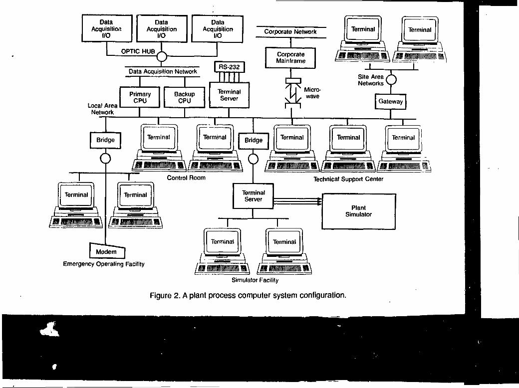
DataAcquisition
I/O
DataAcquisition
I/O
DataAcquisition
I/O
OPTIC HUB ^
Corporate Network
Local AreaNetwork
Data Acquisition Network
Technical Support Center
Emergency Operating Facility
Simulator Facility
Figure 2. A plant process computer system configuration.

Flows
Pressures
Levels
Temperatures
Component Status
HumanMachineInterface
• Valves• Pumps•Circuit Breakers
ALARM DISPLAY
DESCRIPTIONRCS TEMPRCS PRESSPZR LEVEL
VALUE UNITS STATUSXXX DEGF GOOD
YYYY PSIA HIGHZZZ INCH LOW
Plant Monitoring & Performance
ReactorPowerLevel
Time
Figure 3. Plant Process Computer System Software Functional Relationship.

Plant Instrumentation
Data
Data Storage
SystemDisk
">
DataDisk
( Tape \ ^. Drive I
Acquisition Unit
\
Processing
>,
upp
w
I
1LAN
to othersystems
unu
/
1
RS-232To modems/
terminals
im
Peripherals
CRT
WSSSm 1
•ннЦDisplayDriver
LinePrinter
VideoCopier
Communications Links
Figure 4. General plant process computer system hardware functionality.
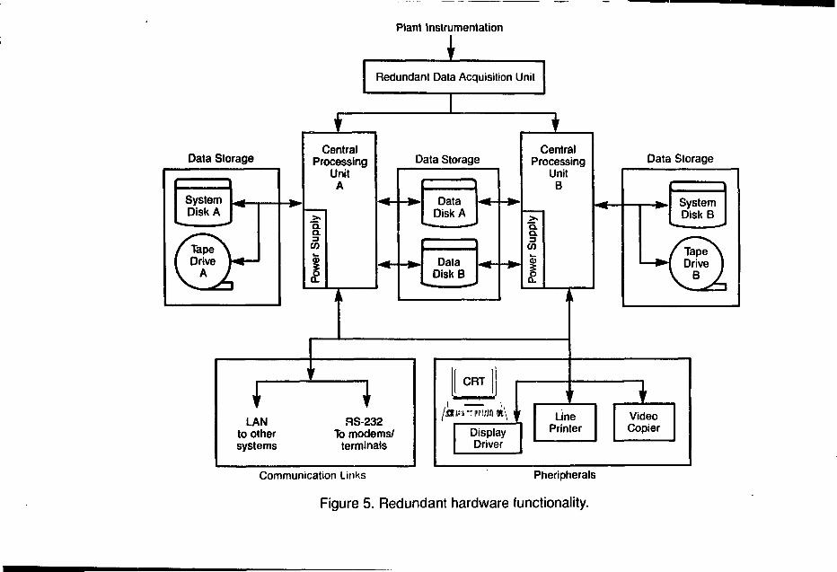
Plant Instrumentation
Data Storage
SystemDisk A
> - — > ^
If Tape \
Drive
v A A^ —
1
J?
LANto othersystems
Redundant Data Acquisition Unit
1
CentralProcessing
UnitAA
Q.
Pow
er S
i
I i
Data Storage
_^_
^ i n
• DataDisk A
. DataDisk В
\ r
\IT
aS-232To modems/
terminals
CentralProcessing
UnitQD
Q.
Pow
er S
i
i
["CRT
DisplayDriver
Data
LinePrinter
^
VideoCopier
Storage
SystemDisk В
Г T a p e ^Drive 1
l В J
Communication Links Pheripherals
Figure 5. Redundant hardware functionality.
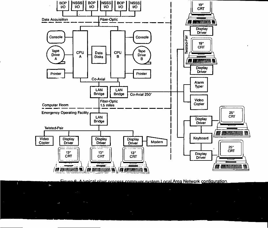
BOPI/O
NSSSI/O
BOPI/O
1 1 1Data Acquisition
NSSSl1/0
IFiber-Op.
BOPI/O
NSSSI/O
I IData Acquisition Fiber-optic •— — — —— —— — — — ——. — _ _ — _ _ _ ^ _ ___ _ _ — __^
1
CPU
в —1
f \Console
f ТареГ\Drive ]
V B ÀPrinter I
ILAN
Bridge Co-Axial 250'
Fiber-OpticComputer Room 1.5 miles I
Emergency Operating Facility
Twisted-Pair
Modem
J ЯВЯТ.' J, J -ДДДДД
Network

CONTRIBUTORS TO DRAFTING AND REVIEW
Mr. W.Aleite
Mr. A. Andersson
Mr. O. Andersson
Mr. J.M.Barache
Mr W.Bastl
Mr. A.D.Boothroyd
Mr. A.B.Cook
Mr. M.Dusic
Mr. A.V. Elshin
Siemens AG, KWU GroupP.O. Box 3220D-91050 ErlangenGermany
Swedish State Power BoardRinghals Nuclear Power StationS-430 22 VërobackaSweden
Swedish State Power BoardForsmark Power StationS-742 03 OsthammarSweden
Chef du Départ. InformationElectricité de France6 Rue Ampere93208 Saint-DenisFrance
Ges. fur Reaktorsicherheit mbHForschungsgelaendeD-8S748 GarchingGermany
International Atomic Energy AgencyDivision of Nuclear PowerWagramestrasse 5, P.O.Box 100A-1400 Vienna, Austria
Canatom Inc.184 Front Street East, 5th Floor,Toronto, Ontario M5A 4N3Canada
International Atomic Energy AgencyDivision of Nuclear SafetyWagramestrasse 5, P.O.Box 100A-1400 Vienna, Austria
Science and Research Instituteof Technology188 537SosnovyBorLeningrad RegionRussian Federation
(1)
(1)
(1.4)
(2,3)
(1,2,3,4)
(1,4)
(1,2,3,4)
0)
(4)
191

Mr. A. Ets
Mr. P.Farago
Mr.A. Faya
Mr. K. Hamar
Mr. A.Kossilov
Ms. E. Leret
Mr. I.Lux
Mr. M.T.McPhedran
Mr. G.N. Nozdrin
Mr. A.B. Pobedonostsev
Smarrware Associates, Inc.4805 Davron Street, LaurelMaryland 20707-3105U.S.A.
PAKS Nuclear Power PlantH-7031 Paks, P.O. Box 71Hungary
Atomic Energy BoadOttawa KlP5S9Canada
Nuclear Safety InspectorateP.F. 676, Budapest 14, H-1539Hungary
International Atomic Energy AgencyDivision of Nuclear PowerWagramestrasse 5, P.O.Box 100A-1400 Vienna, Austria
EDF-DFRб, Quai WatierF-78400 ChatouFrance
Central Research Institutefor Physics
Institute for Atomic Energy ResearchH-1525 Budapest 114, P.O. Box 49Hungary
Ontario HydroControl Computers SectionDarlington Engineering Dept.700 University Ave. H16A14Toronto, Ontario M5G 1X6Canada
Institute "Atomenergoprojekt"7 Bakuninskaya str.Moscow 107815Russian Federation
Experimental MachineBuildings
Design BureauBumakovsky prezd, 15603603 Nizhny Novgorod - 74Russain Federation
(4)
(1)
(4)
(4)
(1,2,3,4)
(4)
(1)
0)
0)
(1)
192

Mr. Y.Shinohara
Mr. D.Spohn
Mr. B.Sun
Mr. N. Wall
Mr. D. Welbourne
Systems Safety DepartmentNuclear Power EngineeringCorporation
Fuji ta Kanko Toranomon Bldg., SF3-17-1, Toranomon, Minato-kuTokyo 105
Electricité de FranceService de la Production ThermiqueB.P. 26, 13-27 Espl. Charles de GaulleF-92060 Paris la Défense Cedex 57France
Electric Power ResearchInstitute
Nuclear Power Division3412 Hillview AvenuePalo Alto, CA 94303U.S.A.
Atomic Energy AgencyBuilding B41/309Winfrith, DorchesterDorset DT2 8DHU.K.
NNC Ltd.Warrington RoadRisley, Warrington WA3 6BZU.K.
(1.4)
(1,2,3)
(1,2,3)
(4)
Advisory Group Meetings
Vienna, 17-21 June 1991 (1), Vienna, 2 1 - 2 5 February 1994 (4)
Consultancy Meetings:
Vienna, 2 - 6 December 1991 (2), Vienna 5 - 9 October 1992 (3)
193

IAEA Publications on
Nuclear Power Plants Control and Instrumentation
1984 Nuclear Power Plant Instrumentation and Control. A Guidebook(Technical Report Series No. 259)
1984 Safety-related Instrumentation and Control Systems for Nuclear Power Plants. ASafety Guide (Safety Series, 5O-SG-D8)
1985 Diagnosis of and Response to Abnormal Occurrences at Nuclear Power Plants(IAEA-TECDOC-334)
1987 Improving Nuclear Power Plant Safety Through Operator Aids(1AEA-TECDOC-444)
1988 Man-Machine Interface in the Nuclear Industry' (Proceedings of InternationalConference, Tokyo, 15-19 February, 1988 (STI/PUB/781)
1988 Manual on Quality Assurance for Computer Software Related to the Safety of NuclearPower Plants (Technical Reports Series No. 282)
1989 Manual on Quality Assurance for Installation and Commissioning of Instrumentation,Control and Electrical Equipment in Nuclear Power Plants(Technical Report Series No. 301)
1990 Control Rooms and Man-Machine Interface in Nuclear Power Plants(1AEA-TECDOC-565)
1990 Reviewing Computer Capabilities in Nuclear Power Plants (1AEA-TECDOC-561 )
1991 Safety Implications of Computerized Process Control i.i Nuclear Power Plants(IAEA-TECDOC-581)
1992 Balancing Automation and Human Actions in Nuclear Power Plants (Proceedings ofInternational Symposium, Munich, 9-13 July, 1990 (STI/PUB/843)
1992 Expert Systems in the Nuclear Industry (IAEA-TECDOC-660)
1992 The Role of Automation and Human in Nuclear Power Plants (IAEA-TECDOC-668)
1992 Safety Analysis of Nuclear Power Plant Automation and Robotics (IAEA-TECDOC-672)
194

ABBREVIATIONS
AGRBWRCADCANDUCRTDDCEOPEQESFI&CIWG NPPCI
LANNPPO&MPLCPWRQAROMSPDSSPINTMIUATPULSVDUV&V
Advanced Gas-Cooled ReactorBoiling Water ReactorComputer Aided DesignCanadian Heavy-Water ReactorCathode Ray DisplayDistributed Digital ControlEmergency Operating ProceduresEquipment QualificationEngineered Safety FeaturesInstrumentation and ControlInternational Working Group on Nuclear Power PlantControl and InstrumentationLocal Area NetworkNuclear Power PlantOperation and MaintenanceProgrammable Logic ControllerPressurized Water ReactorQuality AssuranceRead Only MemorySafety Parameter Display SystemA French Design c! integrated Digital Protection SystemThree Mile IslandProtection Acquisition and Processing UnitSafeguard Logic UnitVideo Display UnitVerification and Validation
195