Computer-Tomography II - DKFZ
31
1 Seite 1 Uwe Oelfke Computer-Tomography II: Image reconstruction and applications Prof. Dr. U. Oelfke DKFZ Heidelberg Department of Medical Physics (E040) Im Neuenheimer Feld 280 69120 Heidelberg, Germany [email protected] Uwe Oelfke Contents Motivation for CT B i Ph i H fi ld U it Basic Physics – Hounsfield Units Technical aspects: CT scanner CT reconstruction Spiral- and multi-slice CT Image quality Image quality Clinical applications
Transcript of Computer-Tomography II - DKFZ

1
Seite 1
Uwe Oelfke
Computer-Tomography II:
Image reconstruction and applications
Prof. Dr. U. OelfkeDKFZ HeidelbergDepartment of Medical Physics (E040)Im Neuenheimer Feld 28069120 Heidelberg, [email protected]
Uwe OelfkeContents
Motivation for CT
B i Ph i H fi ld U it Basic Physics – Hounsfield Units
Technical aspects: CT scanner
CT reconstruction
Spiral- and multi-slice CT
Image quality Image quality
Clinical applications

2
Seite 2
Uwe Oelfke
CT- Reconstruction
Radon-transform
Backprojection
Filtered backprojection
Uwe OelfkeRadon-transform
Measurement: Line-integrals of attenuation coefficient distribution
A
rdnrprdlyxp ²)ˆ()(),()(
Sinogram: All projections as function of Φ,p:
)]([),( rRp
)()( ),(),( pyx
3
Seite 3
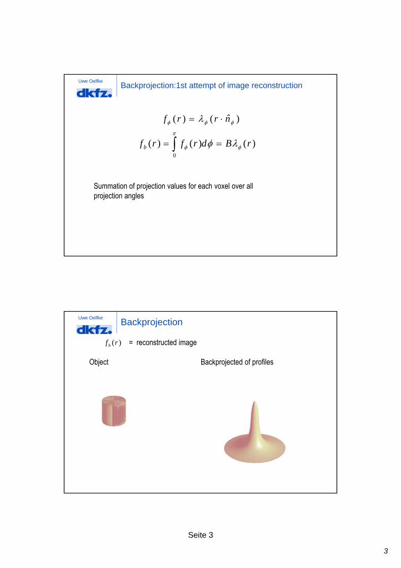
Uwe OelfkeBackprojection:1st attempt of image reconstruction
)ˆ()( nrrf
)()()(0
rBdrfrfb
Summation of projection values for each voxel over all projection angles projection angles
Uwe OelfkeBackprojection
Object Backprojected of profiles
= reconstructed image )(rfb

4
Seite 4
Uwe OelfkeBackprojection = Convolution with PSF
'²|'|
1)'()( rd
rrrrf
A
b Convolution:
1)(
rrhKernel, PSF
)()()( rBRrBrfb
))(()( rhrfb Deconvolution ?
))(()(f b
Uwe OelfkeImage reconstruction via deconvolution
Convolution theorem:
)()())(( 222 rhFrFrhF 222
1)()(
HrhF
1)(
rrhKernel, PSF
2 )()( HrhF

5
Seite 5
Uwe OelfkeTheory:Image reconstruction via deconvolution
)()( 21
2 rBRFFrf
1. Backprojection
2. 2D-Fourier-transform
3. Multiplication with filter
4 In erse 2D Fo rier transform4. Inverse 2D-Fourier-transform
Uwe OelfkeCentral Slice-Theorem
Disadvantage of deconvolution approach: alle projections have to be known
Central-Slice-Theorem allows image reconstruction during image acquisition
21 FRF

6
Seite 6
Uwe OelfkeImage reconstruction: Filtered backprojection
11
11 FBFR
1. 1d-Fourier transform of projection profile
2. Multiplication with filter (kernel)
3. 1d-inverse Fourier transform
4. Backprojection
Uwe OelfkeFiltered backprojection
Object Filtered backprojection

7
Seite 7
Uwe Oelfke
Ungefilterte RückprojektionBackprojection of measured profiles
Uwe Oelfke
Filter, kernel
=
Measured profile
Filtered profile

8
Seite 8
Uwe Oelfke
Gefilterte RückprojektionBackprojection of filtered profiles
Uwe OelfkeFiltered backprojection
SinogramObject
Image acquisition
FilteredSinogram
filteringTomogramm
Back-projection Projektionswinkel
Fächerwinkel

9
Seite 9
Uwe OelfkeSpiral-CT (1989)
Continuosly rotating CT-gantry and continous patient transport spiral CT
Uwe OelfkeSpiral-CT reconstruction
Requires interpolation of data
additional reconstruction algorithms
10
Seite 10
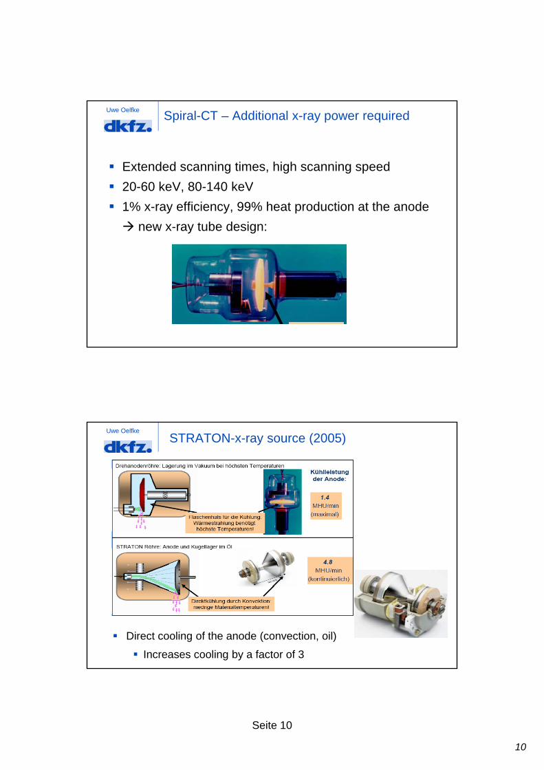
Uwe OelfkeSpiral-CT – Additional x-ray power required
Extended scanning times, high scanning speed
20 60 k V 80 140 k V 20-60 keV, 80-140 keV
1% x-ray efficiency, 99% heat production at the anode
new x-ray tube design:
Uwe Oelfke
STRATON-x-ray source (2005)
Direct cooling of the anode (convection, oil)
Increases cooling by a factor of 3
11
Seite 11
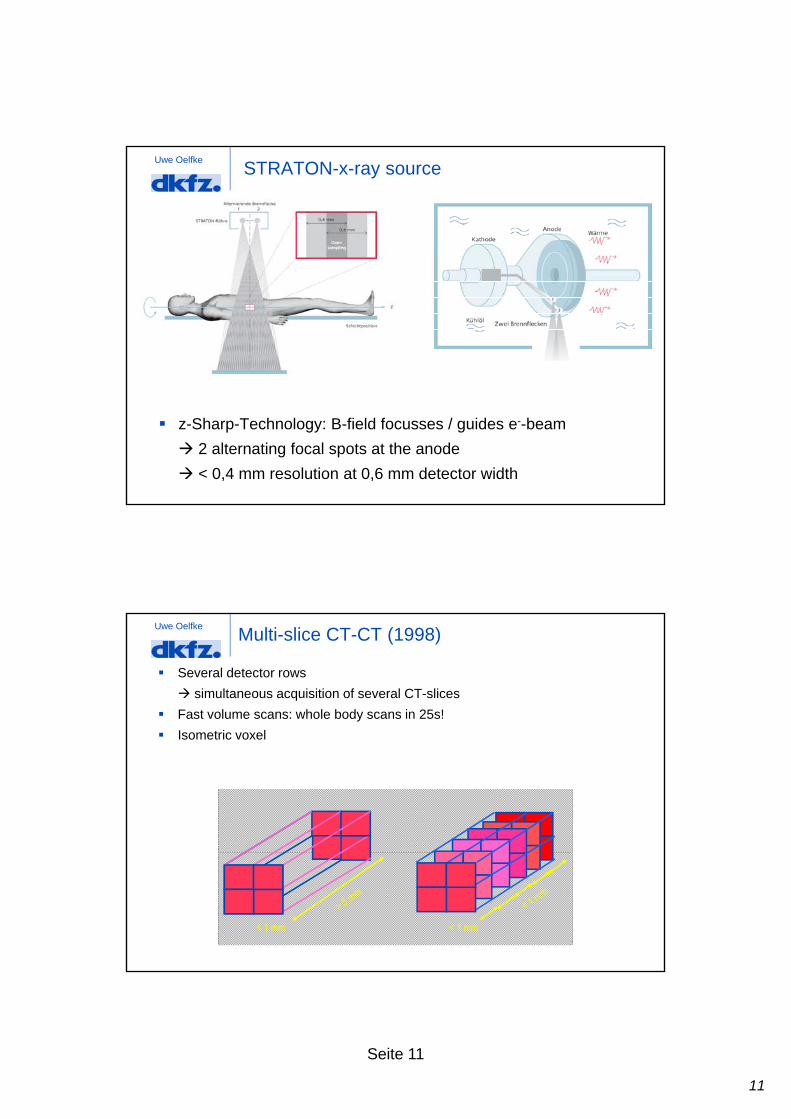
Uwe OelfkeSTRATON-x-ray source
z-Sharp-Technology: B-field focusses / guides e--beam
2 alternating focal spots at the anode
< 0,4 mm resolution at 0,6 mm detector width
Uwe OelfkeMulti-slice CT-CT (1998)
Several detector rows
simultaneous acquisition of several CT-slices
Fast volume scans: whole body scans in 25s!
I t i l Isometric voxel
< 1 mm < 1 mm

12
Seite 12
Uwe OelfkeCone beam-CT
Uwe OelfkeAdaptive array detector

13
Seite 13
Technical developments 1972 - 2000
1972 1980 1990 2000
min. scan time
data per 360 scan
data per spiral scan
image matrix
tube power
300 s 5 s 1 s 0.5 s
58 kB 1 MB 2 MB 12 MB
- - < 50 MB < 500 MB
80 x 80 256 x 256 512 x 512 512 x 512
2 kW 10 kW 40 kW 60 kW
slice thickness
spatial resolution
contrast resolution
13 mm 2 - 10 mm 1 - 10 mm 0.5 - 5 mm
3 lp/cm 12 lp/cm 15 lp/cm 24 lp/cm
5 mm / 5 HU / 50 mGy
3 mm / 3 HU / 30 mGy
3 mm / 3 HU / 30 mGy
3 mm / 3 HU / 30 mGy
Uwe Oelfke
Image quality

14
Seite 14
Uwe OelfkeImage quality indicators
Indicators:
ti l l ti spatial resolution
contrast
noise, homogeneity
artefacts
Uwe OelfkeSpatial resolution
There are 7 or 8 mice...
No, there are10 of them!
The ability to resolve High Contrast Objects,- High Contrast Resolution

15
Seite 15
Uwe OelfkeSpatial resolution
Edge enhancement filter Smoothing filter
Uwe Oelfke
When Small Contrast differences are questioned - Low Contrast Resolution
!
Contrast resolution
Is therea cat? ! There
could bea cat!
A cat !

16
Seite 16
Uwe OelfkeContrast resolution
Edge enhancement filter Smoothing filter
Uwe OelfkeContrast detail diagram

17
Seite 17
Uwe OelfkeNoise
Poisson statistics of photons
Depends on x-ray current I, slice thickness d
I = 50 mAd = 4 mm
I = 200 mAd = 4 mm
I = 200 mAd = 16 mm
Uwe OelfkeCARE-Technology
Volumes with low attenutation contribute less to image noise
potential reduction of dose without loss of image qualityp g q y
Dynamic adaptation of output of the x-ray source to the expected attenuation
dose reduction of up to 68%
18
Seite 18
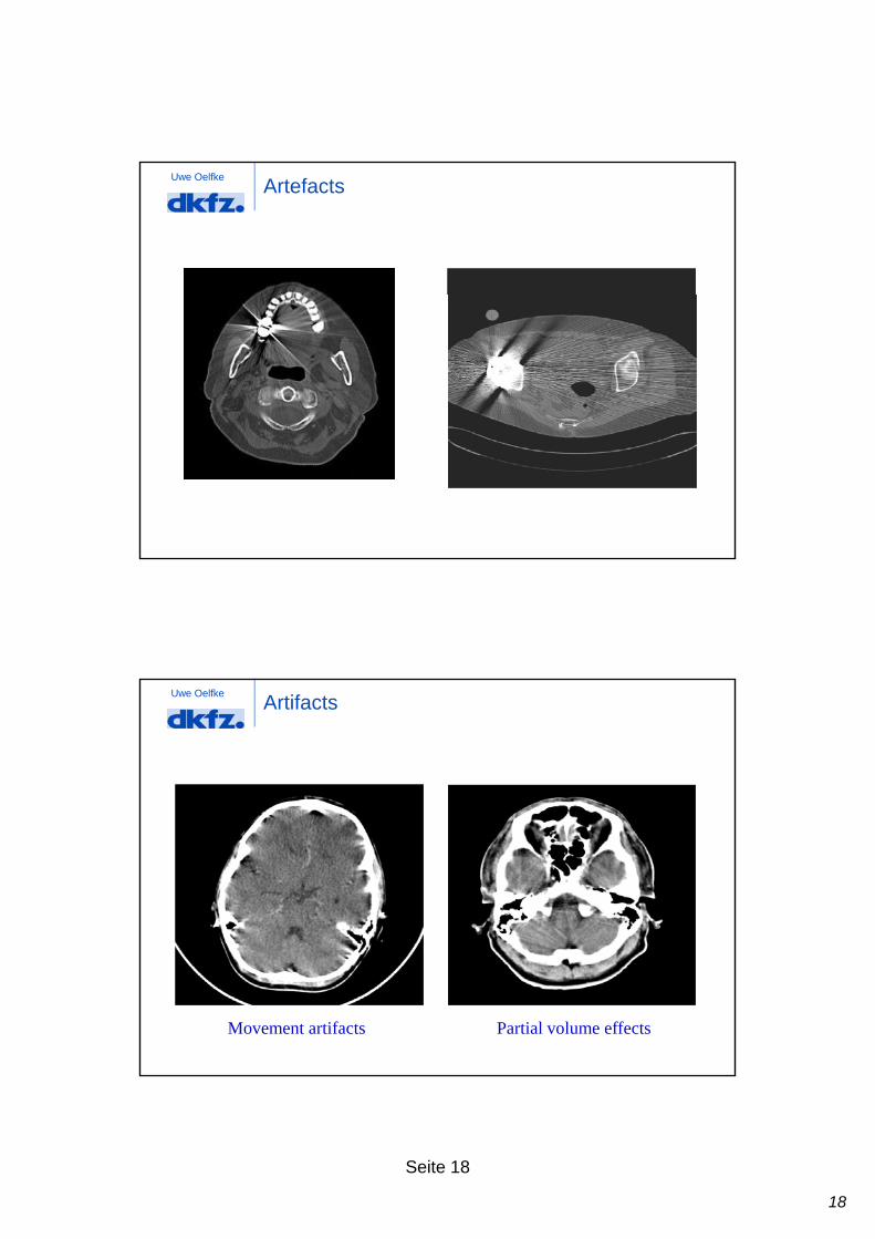
Uwe OelfkeArtefacts
Uwe OelfkeArtifacts
Movement artifacts Partial volume effects

19
Seite 19
Uwe OelfkeInfluence of different reconstruction kernels
Uwe OelfkePartial volume effect
CT-slice
BoneSoft tissue

20
Seite 20
Uwe OelfkePartial volume effect
CT-slice
BoneSoft tissue
Uwe OelfkePartial volume effect
CT-slice
BoneSoft tissue

21
Seite 21
Uwe Oelfke
Clinical applications
Uwe OelfkeRoutine applications
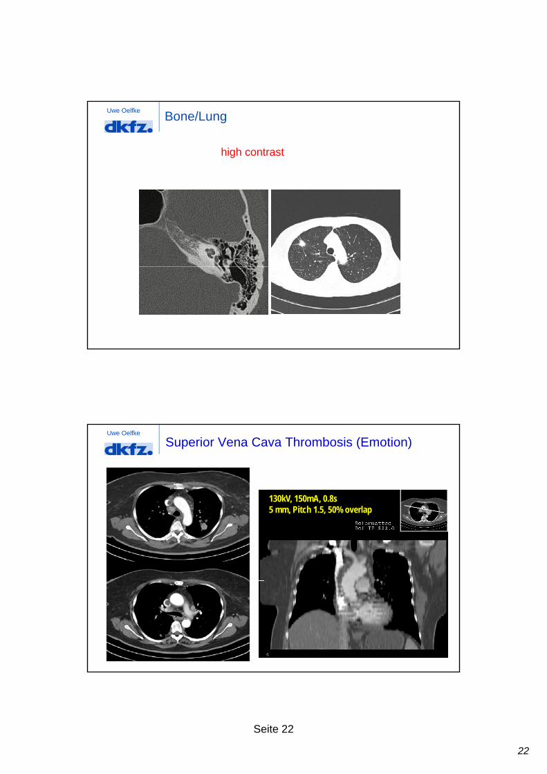
Bones & Lungs
Soft Tissues
22
Seite 22
Uwe Oelfke
high contrast
Bone/Lung
Uwe Oelfke
Superior Vena Cava Thrombosis (Emotion)
130kV, 150mA, 0.8s5 Pit h 1 5 50% l5 mm, Pitch 1.5, 50% overlap
23
Seite 23
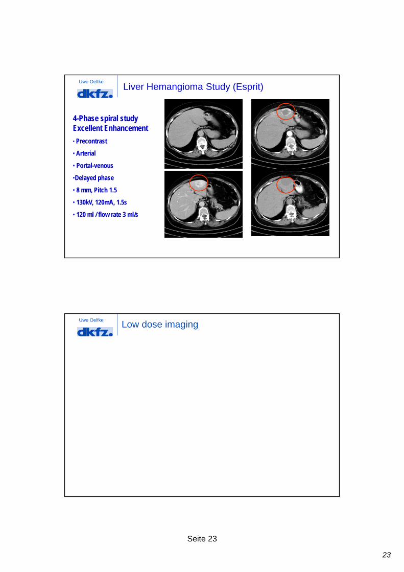
Uwe OelfkeLiver Hemangioma Study (Esprit)
4-Phase spiral studyExcellent Enhancement
• Precontrast
• Arterial
• Portal-venous
•Delayed phase
• 8 mm, Pitch 1.5
• 130kV, 120mA, 1.5s
• 120 ml / flow rate 3 ml/s
Uwe OelfkeLow dose imaging

24
Seite 24
Uwe OelfkeBroken heel – 1mm Spiral CT
Emotion - Sagittal Reformat Volume Access - VRT
Uwe Oelfke
Spine (Emotion/Emotion Duo)
• 2 mm, Pitch 2
• Low dose ( 90 mA)
• Low Dose of 100 mAs
• 2 x 1.5 mm collimation
• 2 mm slice width
99 i l d ti• 99 s spiral duration

25
Seite 25
Uwe Oelfke
Pediatrics Head (Emotion Duo)
2 x 1mm, 60 mAs
1.25mm axial slice
Uwe OelfkeCT Angiography
26
Seite 26
Uwe Oelfke
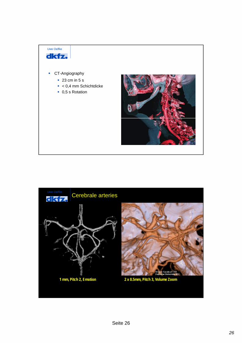
CT-Angiography
23 cm in 5 s23 cm in 5 s
< 0,4 mm Schichtdicke
0,5 s Rotation
Uwe Oelfke
Cerebrale arteries
1 mm, Pitch 2, Emotion 2 x 0.5mm, Pitch 3, Volume Zoom
27
Seite 27
Uwe Oelfke
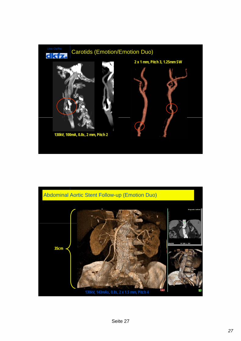
Carotids (Emotion/Emotion Duo)
2 x 1 mm, Pitch 3, 1.25mm SW
130kV, 100mA, 0.8s, 2 mm, Pitch 2
Uwe Oelfke
Abdominal Aortic Stent Follow-up (Emotion Duo)
35cm
130kV, 143mAs, 0.8s, 2 x 1.5 mm, Pitch 4

28
Seite 28
Uwe OelfkeMehrschicht-CT
Uwe OelfkeIntrafractional Movement by 4D-MSCT on a Siemens Sensation open
Lung cancerT4N3T4N3
paralysis of rt diaphragm
29
Seite 29
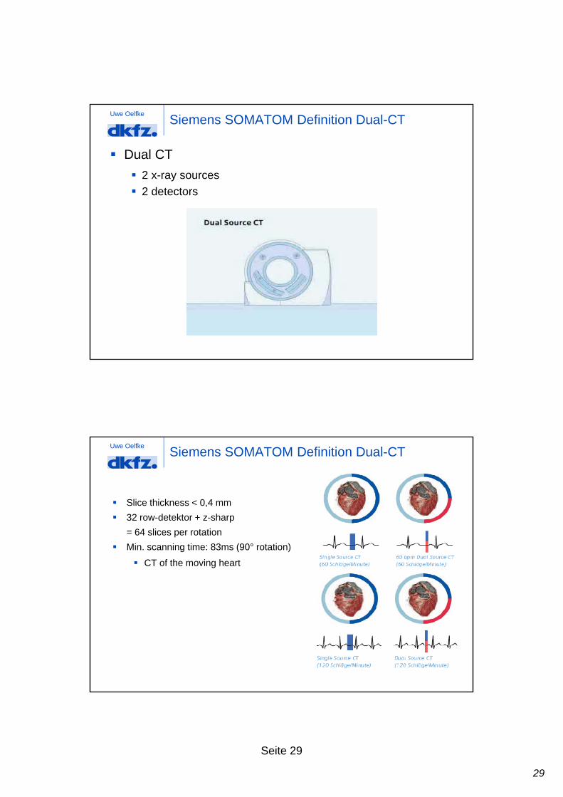
Uwe OelfkeSiemens SOMATOM Definition Dual-CT
Dual CT
2 x-ray sources
2 detectors 2 detectors
Uwe OelfkeSiemens SOMATOM Definition Dual-CT
Slice thickness < 0,4 mm
32 row-detektor + z-sharp p
= 64 slices per rotation
Min. scanning time: 83ms (90° rotation)
CT of the moving heart

30
Seite 30
Uwe Oelfke
"Dual Energy"
Scanning with two x-ray sources at different energies
Energy dependence of attenuation coefficient
Siemens SOMATOM Definition Dual-CT
additional contrast
Uwe OelfkeToshiba 256-slices CT
128 mm scan-width at 0,5 mm slice thickness
whole heart imaging in one rotation

31
Seite 31
Uwe Oelfke4D-CT Toshiba 256-slice-CT