COMPUTER RIDE DIAGNOSTIC WHEEL … RIDE DIAGNOSTIC WHEEL BALANCER OPERATION INSTRUCTIONS Form...
50
COMPUTER RIDE DIAGNOSTIC WHEEL BALANCER OPERATION INSTRUCTIONS Form ZEEWB519A Rev E April .02.10 BFH 1000 and BFH 1000 Super EEWB519B and EEWB519S
Transcript of COMPUTER RIDE DIAGNOSTIC WHEEL … RIDE DIAGNOSTIC WHEEL BALANCER OPERATION INSTRUCTIONS Form...

COMPUTER RIDE DIAGNOSTICWHEEL BALANCER
OPERATION INSTRUCTIONS
Form ZEEWB519A Rev E April .02.10
BF
H 1
000
and
BF
H 1
000
Su
per
EE
WB
519B
an
d E
EW
B51
9S

Blank page

SAFETY INFORMATION
For your safety, read this manual thoroughlybefore operating the BFH 1000 or BFH 1000 Super Wheel Balancers
The JBC BFH 1000 and BFH 1000 Super Ride Diagnostic Wheel Balancers are in-tended for use by properly trained automotive technicians. The safety messages pre-sented in this section and throughout the manual are reminders to the operator to exer-cise extreme caution when servicing tires with these products.
There are many variations in procedures, techniques, tools, and parts for balancingtires, as well as the skill of the individual doing the work. Because of the vast number ofwheel and tire applications and potential uses of the product, the manufacturer cannotpossibly anticipate or provide advice or safety messages to cover every situation. It isthe automotive technician's responsibility to be knowledgeable of the wheels and tiresbeing serviced. It is essential to use proper service methods in an appropriate andacceptable manner that does not endanger your safety, the safety of others in the workarea or the equipment or vehicle being serviced.
It is assumed that, prior to using the BFH 1000 or BFH 1000 Super Ride DiagnosticWheel Balancer, the operator has a thorough understanding of the wheels and tiresbeing serviced. In addition, it is assumed he has a thorough knowledge of the operationand safety features of the rack, lift, or floor jack being utilized, and has the proper handand power tools necessary to service the vehicle in a safe manner.
Before using the BFH 1000 or BFH 1000 Super Ride Diagnostic Wheel Balancer,always refer to and follow the safety messages and service procedures provided by themanufacturers of the equipment being used and the vehicle being serviced.
IMPORTANT !! SAVE THESE INSTRUCTIONS -- DO NOT DISCARD !!
I

IMPORTANT SAFETY INSTRUCTIONS
When using this equipment, basic safety precautions should always be followed, including thefollowing:
1. READ ALL INSTRUCTIONS.
2. Do not operate equipment with a damaged power cord or if the equipment has beendamaged - until it has been examined by a qualified authorized service technician.
3. If an extension cord is used, a cord with a current rating equal to or more than thatof the machine should be used. Cords rated for less current than the equipmentmay overheat. Care should be taken to arrange the cord so that it will not be trippedover or pulled.
4. Always unplug equipment from electrical outlet when not in use. Never use thecord to pull the plug from the outlet. Grasp plug and pull to disconnect.
5. To reduce the risk of fire, do not operate equipment in the vicinity of opencontainers of flammable liquids (gasoline).
6. Keep hair, loose fitting clothing, fingers and all parts of the body away from movingparts.
7. Adequate ventilation should be provided when working on operating internalcombustion engines.
8. To reduce the risk of electric shock, do not use on wet surfaces or expose to rain.
9. Do not hammer on or hit any part of the control panel with weight pliers.
10. Do not allow unauthorized personnel to operate the equipment.
11. Do not disable the hood safety interlock system or bypass the intended operation.
12. Use only as described in this manual. Use only manufacturer’s recommendedattachments.
13. Always make sure the power clamp is sucure before spinning the shaft.
14. ALWAYS WEAR SAFETY GLASSES. Everyday eyeglasses only have impactresistant lenses, they are NOT safety glasses.
15. Balancer is for indoor use only.
16. This equipment uses class II lasers. Do not look into or allow by standers to look into thelaser source.
SAVE THESE INSTRUCTIONS
II

CAUTION! This product uses LASER RA-DIATION for measurements. DO NOTSTARE INTO BEAM.
Refer to these laser safety state-ments whenever this sign is dis-played.
Peak power 1.0 mW.Pulse duration 5 m sec.Emitted wavelength 650nm.
Class II laser product. Caution - the use ofoptical instruments with this product willincrease risk of eye hazard.
WARNING!!! DO NOT STARE INTO LA-SER BEAM! EYE INJURY MAY OCCURWITH PROLONGED EYE CONTACTWITH LASER. AVOID EYE CONTACTWITH THE LASER SCANNERS
DO NOT KNOCK OR TAMPER WITH THELASER SCANNERS
CAUTION! - Use of Controls or adjustmentsor performance of procedures other thanthose specified herein may result in haz-ardous radiation exposure.
WARNING!!! IN THE EVENT OF MA-CHINE MALFUNCTION, DO NOT LOOKINTO THE LASER AREA. PROLONGEDEXPOSURE TO THE LASER MAYCAUSE EYE INJURY.
PERFORM REGULAR CLEANING OF THELASER SCANNER GLASS TO ENSUREOPTIMUM OPERATION.
ALWAYS OPERATE THE WHEEL BAL-ANCER WITHIN THE RANGES STATED INTHE LABEL SHOWN BELOW.
III
WARNING!!!SEVERE PERSONAL IN-JURY WILL OCCUR IF FINGERS ORHAND IS PINCHED BETWEEN THECLAMP NUT, WHEEL OR FLANGE

IV

Table of Contents
SAFETY INFORMATION ...................................................................................................................11.0 INTRODUCTION .....................................................................................................................31.1 SAFETY NOTICE ....................................................................................................................41.2 BALANCER APPLICATION......................................................................................................41.3 BFH 1000 SPECIFICATIONS ..................................................................................................41.4 FEATURES .............................................................................................................................51.7 DIMENSIONS OF THE MACHINE ...........................................................................................71.8 INSTALLATION AREA REQUIREMENTS ................................................................................81.9 INSTALLATION PRECAUTIONS .............................................................................................82.1 ELECTRIC INSTALLATION .....................................................................................................92.2 SETUP ....................................................................................................................................92.2.2 CUSTOMIZING OPTIMA FEATURES .................................................................................... 113.0 PHYSICAL LAYOUT. ..............................................................................................................123.1 THE DISPLAY SCREEN........................................................................................................123.2 MENU KEYS ..........................................................................................................................133.2.2 MAIN MENU FUNCTIONS......................................................................................................143.2.3 BALANCING ..........................................................................................................................143.2.8 FUNCTION (SETUP) .............................................................................................................164.0 HELP INFORMATION ............................................................................................................175.0 POWER CLAMP ...................................................................................................................186.0 OPERATION OF THE BALANCER .......................................................................................196.1 CHECK LIST - INSPECTION ................................................................................................196.2 BALANCE SCREEN DESCRIPTION ....................................................................................206.2.1 WHEEL MOUNTING ..............................................................................................................216.2.2 STANDARD WHEELS (BACK CONE MOUNT) ...................................................................216.2.3 CENTERING LIGHT-TRUCK WHEELS ................................................................................216.3 SCAN MODE SELECTION ...................................................................................................226.4 SPINNING THE WHEEL ........................................................................................................236.5 SELECTING THE WEIGHT PLACEMENT ........................................................................... 236.6 CORRECTION OF THE IMBALANCE...................................................................................246.6.1 PROCEDURE WHEN SCANNER FAILS TO ACQUIRE A VALID PROFILE .........................246.7 VERIFICATION OF THE RESULTS.......................................................................................246.8 VIBRATION PROBLEMS .......................................................................................................257.0 SPOKE BALANCING MODE .................................................................................................258.0 OPTIMA PROCEDURES .....................................................................................................268.1 SELECTING MODE ..............................................................................................................268.2 BEGIN DIAGNOSTIC RUN ....................................................................................................268.3 PROFILING THE WHEEL .....................................................................................................268.4 OPTIMA GEOMETRIC MATCHING .......................................................................................288.4 BARE RIM DIAGNOSIS .........................................................................................................309.0 OPTILINE, BALANCING A SET OF WHEELS .......................................................................319.1 OPTILINE CUSTOMER CALIBRATION.................................................................................3410.0 WEIGHT MANAGEMENT.......................................................................................................3611.0 USER CALIBRATION ............................................................................................................3912.0 EXPLANATION OF PROGRAM CODES ..............................................................................4013.0 MAINTENANCE .....................................................................................................................4214.0 TROUBLE SHOOTING .........................................................................................................42


Page 3
John Bean BFH 1000 Series Operators Manual
1.0 INTRODUCTION
Congratulations on purchasing the BFH 1000 Series Computer Ride Diagnostic Wheel Balancer. This wheel bal-ancer is designed for ease of operation, accuracy, reliability and speed. With proper maintenance and care yourwheel balancer will provide many years of trouble-free operation.
BFH Ride Diagnostics Balancer - Precautions To Observe
Your BFH 1000 Series Ride Diagnostics Balancer utilizes the latest in electronics and instrumentation technology,incorporating three separate scanning lasers along with an embedded computer (PC). Following the precautionslisted below will help to ensure continuous and satisfactory operation of your unit.
1) Install the balancer on a dedicated power line in order to avoid electrical noise and power line fluctuations. Avoidpower cord length greater that 15 feet.
2) The BFH1000 Series Ride Diagnostic Wheel Balancer utilizes red scanning lasers which actually create animage of the wheel being diagnosed. Install the balancer away from direct sunlight so that the laser beams canbe detected by the scanner. Avoid placing high intensity lamps and infrared heaters near the BFH balancer.
3) Diagnose and balance only those wheels which fit within the specifications of the BFH Balancer:Manual mode Rim Diameter range is 8 - 30 inches.Automatic Laser Non-Touch mode Rim Diameter and Profile range is 14 - 26 inches.Maximum Tire Diameter in Manual or Automatic mode is 44 inches.Rim Width range in Manual or Automatic mode is 3 - 20 inches.
IMPORTANT: The BFH Laser Scanners can accurately measure parameters and profiles on rims from 14 to26 inches in diameter. For Scanner measurement, a MINIMUM distance is required from the cabinet tothe rim edge. The Distance is measured using the standard distance gauge arm (SAPE).
For rims 14-18 inches in diameter the minimum is 56 mm (2.20 inches)For rims 19-26 inches in diameter the minimum is 81 mm (3.19 inches)
4) The BFH balancer is designed to properly scan the profile of existing rims. Extreme geometric combinations ofrim diameter and flange offset can inhibit the proper viewing of the rim profile. These exceptional rims can beproperly balanced by manually entering the distance, diameter, and width of the rim.
5) The wheel guard of the BFH1000 Series Ride Diagnostic Wheel Balancer also serves as the housing for one ofthe scanning lasers. Since the laser must remain stationary once the spin cycle begins, do not lean on orotherwise disturb the wheel guard until the spin cycle has been completed.
Instructions on use, operational requirements and routine maintenance of the machine are covered in this manual.
This unit uses an open source Linux operating system for its user interface. This open source code is availablefor the cost of shipping and handling to owners of the BFH1000 Series Ride Diagnostic Wheel Balancer.Requests must be made to the attention of balancer product management at the Conway AR address listed onthe back of this manual. Please include the owners name, address and unit serial number with all requests.
STORE THIS MANUAL IN A SAFE PLACE FOR FUTURE REFERENCE.READ THIS MANUAL THOROUGHLY BEFORE USING THE MACHINE.

Page 4
1.1 SAFETY NOTICE
This manual is a part of the balancer product.
Read carefully all safety warnings and instructions of this manual since they provide important information concern-ing safety and maintenance. See Safety Chapter for safety information and warnings page I - IV.
1.2 BALANCER APPLICATION
The John Bean BFH1000 Series Ride Diagnostic Wheel Balancer is intended to be used as a device to balance,diagnose and correct car, and light truck wheel vibration problems within the following range:
Maximum tire diameter : 44” (1117mm)Maximum wheel diameter : 30” (762mm)Maximum wheel width : 20” (381mm)Maximum wheel weight : 154 lbs (70 kg)
This device is to be only used in the application for which it is specifically designed.Any other use shall be considered as improper and thus not reasonable.
The manufacturer shall not be considered liable for possible damages caused by improper, wrong or non reason-able use.
1.3 BFH 1000 SPECIFICATIONS
Weight Imbalance Accuracy .05 oz / 1 gramWeight Placement Resolution ± .7 degreesWeight Imbalance Resolution: Roundoff Mode .25 oz / 5 grams Non-Roundoff Mode .05 oz / 1 gramMax. Shaft Weight Capacity 154 lbs / 70 kgMax.Tire Diameter 44" / 1117 mmRim Width Capacity 3.0"-20" / 76 mm - 508 mmMax. Tire Width 21” / 530 mmRim Diameter Capacity 8"-30"/203mm-762mmBalancing Cycle Time (normal mode) 20 seconds or lessShaft Speed at calculation >200 RPMElectrical 230vac, 1ph, 50-60Hz, 3.2ARequired Work Area 64” x 64” (1626 x1626 mm)Shipping Weight, complete 645 lbs/293kgShipping Dimensions 72"L X 73"W X 63"D (1829x1854x1600mm)Machine Dimensions 64”h 64”w 64”d (1626x1626x1626mm)Actual Weight with Accessories 550 lbsOperating Temperature Range 32-122F / 0-50C

Page 5
John Bean BFH 1000 Series Operators Manual
1.4 FEATURES
• Self test check with every power up cycle.
• Selectable car/light truck limit values
• Advanced Spoke count capability
• Rim-only diagnostics
• Rim cleaning brake control
• Flat spot detection
• On-board diagnostics for easy service issues
• Selectable default weight placement mode
• Optional Weight Miser ™ and Weight Wizard™ applications
• Advanced Help screens with illustrations
• Pre-programmed Error Codes indicate procedural errors or safety concerns.
• Fully Automatic All-Parameter Data Entry.
• Fully Automatic Rim/Tire Profiling.
• Fully Automatic Spoke/Split Weight Function for Hidden Weight Placement.
• Fully Automatic Left and Right Radial & Lateral Runout Measurements.
• Bare Rim Radial and Lateral Runout Measurement
• Tire Tread Depth Measurement.
• Hands-Free Power Clamping for Precise Wheel Placement.
• Fast Tire/Wheel Diagnostic System Time, Floor-to-Floor.
• Captured back spring eliminates having to handle the backing spring.
• Automatic recalculation if weight positions are changed. No need for re-spinning the wheel.
• Common 40 mm diameter mounting shaft.
• Easy-to-Read LCD Data Display Monitor.
• Dynamic and single weight Static capability.
• Stop-at-Top features simplifies weight imbalance location
• Automatic Weight Type Selection Based on Rim Profile, Indicated by Color Coded Icons
• Optima Balance feature for reducing weight required.
• Built-in spin counter for monitoring balancer productivity.
• Service code access to all Balancer electronic functions for fast, easy diagnosis.
• Operator selectable round-off mode.
• Weight Managment Software, including Optional Weight Miser ™ and Weight Wizard ™• Wheel pull index, option (standard on BFH 1000 Super)
• Wheel runout in multiple positions, optional feature (standard on BFH 1000 Super)

Page 6
Figure 1- Standard Accessories
1.5 STANDARD ACCESSORIES
Standard accessories (Figures 1, and 2,) included withthe BFH 1000 are:
1 EAM0005D40A Weight - Calibration2 EAC0060G02A Flange - Cover, Hook3 EAM0006G01A Pin - Accessory4 58839 Weight Pliers5 EAA0247G21A Caliper - Rim Width6 EAA0283D53A Power Clamp Nut
Power Clamp Nut Accessories, fig 2:A EAC0058D15A Soft Protective RingB EAC0058D07A Cup - Large PressureD EAM0005D54A Plastic SleeveE EAC0058D08A Small Presure Disk
Figure 2 - Power Clamp Nut Accessories
1.6 OPTIONAL ACCESSORIES
4 PC Cone Kit, p/n EAK0221J60A, contains:A EAM0003J08A Cone, 85-132 mm / 3.3”-5.2”B EAM0003J07A Cone, 71-99 mm / 2.8”-3.9”C EAM0003J06A Cone, 56-84 mm / 2.2”-3.3”D EAM0003J05A Cone, 43-63 mm / 1.7” - 2.5”
7PC Cone Kit, p/n EAK0221J31A, contains:A EAM0003J64 Cone 1.70" T0 2.23"B EAM0003J65 Cone 2.03" T0 3.17"C EAM0003J66 Cone 2.38" T0 3.51"D EAM0003J67 Cone 2.74" T0 3.87"E EAM0003J68 Cone 3.08" T0 4.21"F EAM0003J69 Cone 3.42" T0 5.40"G EAM0003J70 Cone 4.21" T0 6.30"
Page 7
John Bean BFH 1000 Series Operators Manual
Figure 4 - Footprint Requirements
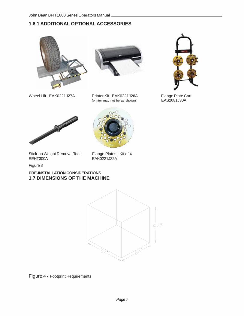
1.6.1 ADDITIONAL OPTIONAL ACCESSORIES
Wheel Lift - EAK0221J27A Printer Kit - EAK0221J26A Flange Plate Cart(printer may not be as shown) EAS2081J30A
Stick-on Weight Removal Tool Flange Plates - Kit of 4EEHT300A EAK0221J22A
PRE-INSTALLATION CONSIDERATIONS1.7 DIMENSIONS OF THE MACHINE
Figure 3

Page 8
1.8 INSTALLATION AREA REQUIREMENTS
Make sure that from the operating position the user can see all of the machine and the surrounding area.
The operator should prevent non authorized persons and/or objects from entering the area which may createpotential hazards.
The machine should be installed on a stable level floor. Do not install the machine on a uneven floor.
If the balancer is to be installed on a raised floor, the floor must have a capacity of at least 110lbs per sq ft. (5000N/m² - 500 kg/m²).
It is not required to secure the machine to the floor but is recommended.
Install the machine in a dry, covered area.
The installation of the machine requires a working area of at least 64” x 64” (1626 x1626 mm). See Figure 3
1.9 INSTALLATION PRECAUTIONS
CAUTION! CAREFULLY REMOVE THE BALANCER FROM THE PALLET.Remove the hardware that secures the machine to the pallet and slide the balancer onto the floor where it is tobe installed.
THE UNIT IS HEAVY AND THE WEIGHT IS NOT EVENLY DISTRIBUTED.
DO NOT LIFT THE BALANCER BY THE SHAFT OR WHEEL GUARD FRAME.
DROPPING THE UNIT MAY CAUSE PERSONAL INJURY OR EQUIPMENT DAMAGE.
2.0 INSTALL ACCESSORY PINSA. Install the accessory pins (Figures 5a and 5b). Tighten firmly.B. Install the Cone Accessory tray if installing a BFH 1000 Super Model. See Figure 5b.
C. Place accessories onto the accessory pins or place 7 cone set into tray.
Figure 5a - BFH 1000 Figure 5b - BFH 1000 Super

Page 9
John Bean BFH 1000 Series Operators Manual
2.1 ELECTRIC INSTALLATION
ANY ELECTRICAL WIRING MUST BE PERFORMED BY LICENSED PERSONNEL.
ALL SERVICE MUST BE PERFORMED BY AN AUTHORIZED SERVICE TECHNICIAN.
Check on the plate of the machine that the electrical specifications of the power source are the same as themachine. The machine uses 230VAC (+/- 15%), 50-60Hz, 1Ph, 3.2 Ampere.
NOTE:ANY ELECTRICAL OUTLET INSTALLATION MUST BE VERIFIED BY A LICENSED ELECTRICIAN BEFORECONNECTING THE BALANCER.
NOTE:THIS MACHINE PERFORMS A SELF-TEST ROUTINE ON START-UP. THERE WILL BE A DELAY OF SEV-ERAL MOMENTS BEFORE UNIT IS READY FOR OPERATION. ANY PROBLEMS DETECTED AT START-UP WILL RESULT IN THE DISPLAY OF AN ERROR CODE. PROBLEMS DETECTED DURING OPERATIONARE SAVED TO A LOG FILE WHICH CAN BE RETRIEVED FOR DIAGNOSIS BY A TECHNICIAN.
2.2 SETUPEvery shop has different procedural requirements meaning each machine should be customized to the uniqueservices performed at that location. Most attributes are set from the Main Function menu. A second “Optima”menu allows further customization
2.2.1 Customizing the SystemA. Select the “Function” key (F1) from the “Welcome” menu. The Main Function setup screen appears as inFigure 6.
B. Press and hold the “F6” button and rotate the wheel to scroll up or down to the desired line item.
C. Press and hold the “F5” button and rotate the wheel to change selected topic to desired value or function.
D. When the desired features have been selected, save selections to permanent memory by selecting line item “3”.Hold the F5 button while rotating the shaft, enter a value of “1”, release to Save to Permanent Memory. SeeFigure 7a next page for complete menu listing.
E. Select the “ESC” button on the keyboard to return to the main screen.
Figure 6

Page 10
Figure 7a - Complete Function Menu listing

Page 11
John Bean BFH 1000 Series Operators Manual
2.2.2 CUSTOMIZING OPTIMA FEATURES• From the “Welcome” Screen or Balance Screen, select the “F6” Optima button.
• Select the “F3” Key to enter the menu used to set the limits required for an Optimization procedure.
• Set the values for measurement limits as required by the shop in lines 1-4 and 13-16. See Figure 7b
D. Line Item 5 allows the user to select the option of making a profile measurement with each spin or only aftera clamping cycle. Select option “0” (only after clamping) allows a quicker floor to floor time. The unit will thenprofile the next wheel assembly after it is clamped. It considers each subsequent spin to be a check spin usingthe same parameters and profile.
E. Advanced Options selection will activate the “Optiline” feature available with the BFH1000 Super. See page28 for Operation details.
F. Advanced Spoke Detection will enable a multiple pass spoke counter. When enabled the spoke counter willattempt to detect spoke in mutiple locations.
G. Enable or disable Flat Spot Detection. This feature will detect an abnormally worn area of a tire.
H. Measure Wheel runout in multiple positions if only a wheel is mounted for bent rim diagnosis.
I. Save the values selected by scrolling down to line item 8, (Save to Memory) while rotating the shaft, enter avalue of “1”, release to Save to Permanent Memory
NOTE: It is recommended that default values be used until which time the users feel they can customizethe menus for desired results.
Figure 7b

Page 12
Figure 8
Figure 9
3.0 Physical Layout.Refer to Figure 8. - Functional description of the unit:
1. The screen2. Input panel3. Gauge arm4. Stub shaft with power clamp nut5. Brake and clamp control pedal6. Weight compartments7. Storage areas for cones or clamping devices8. Tilting frame and hood guard9. Outer scanner10. Rear scanner11. Inner scanner12.Main Power switch (ON/OFF), rearNOTE: shown with optional wheel lift, not included
3.1 The Display ScreenSee Figure 9, Screen with display fields
1-5 Information fields6 Menu fields and Function descriptors.7 Display field of screen
The screen reads out inputs, helpful information,all measured data and error codes.
Detailed description of display fields
The screen is subdivided into various display fields, eachof which is associated with a certain type of information.
Information fields
1 Number of the installed program versionMachine nameDate and time
2 Selected Menu name3 Selected profiling mode4 Electrical compensation5 Error codes
6 Menu fieldsIcons illustrating special features or functions areviewed in the six menu fields. Under every menufield is the associated menu “F key” which is usedto call the feature illustrated.
7 Display fieldWheel type and rim dimensionsBalancing modesAmount of unbalanceDirection of orientation and correction positionOptima proceduresFunction and Setup MenusOther Graphical information
1
2
3
4
5
6
7

Page 13
Figure 10
a db c
e f
3.2 Menu Keys
3.2.1 Description of Menu Keys
The assignment of the menu keys F1 to F6 is shownin the menu fields above the relative keys on thescreen. The menu keys have different functions andinitiate different actions, depending on the programstep.
- Keys without a symbol in the upper right-hand corneror at the edge initiate an action immediately, suchas F2 on the main screen means to perform acompensation process. See Figure 10.
- Keys with one or more symbols in the upper right-hand corner of the menu field or at the edgesinitiate various actions:
a - Press key to access a sub-menu, e.g. key F4Balancing.
b - Press and hold key down while rotating wheel atsame time, e.g. key F11 Number of spokes.
c - Press key to toggle between two options or states,e.g. key F9 Static / dynamic unbalance.
d - Press key to toggle between several options orstates, e.g. key F21 Weight position for correctionplane.
e - Toggle switch (4 functions): Press edge of key tocarry out the highlighted action, e.g. key F32Character set: move the cursor in the character setto the left, to the right, up or down.
f - Toggle switch (2 functions): Press key on top orbottom to select the highlighted function, e.g. key F8Precision reading of unbalance and mode select.

Page 14
Icon 5 Icon 6
Icon 7a
Icon 8 Icon 9
Icon 7b
Icon 1 Icon 2
Icon 3 Icon 4
Icon 10
3.2.2 MAIN MENU FUNCTIONS
Icon 1 Change to the Function screen
Icon 2 Perform adapter compensation run
Icon 3 Change to the Balancing screen
Icon 4 Change to the OPTIMIZATION MENU
3.2.3 BALANCING
Icon 5 Toggle switch, two functions:
Pressed on top:View and/or edit Data Input (wheel parameters)
Pressed on bottom:Move the laser position pointer to the desiredlocation. Button must be held down as the shaft isrotated. (only when stick-on weights are selected)
Icon 6 Toggle switch, two functions; reading only aslong as the key is pressed (quick reading):
Pressed on top:Precision reading of unbalance, no suppression ofminor unbalance readings.
Pressed on bottom:Toggles through possible placement locations ofweight placement for conventional balancing run.
Icons 7a and 7b Select static unbalance or Selectdynamic unbalance
Icon 8 Number of spokes has been selected andentered.
Icon 9 Number of spokes has not been detected andmust be entered manually if required. Hold the F keywhile rotating the shaft until the desired value isdisplayed.
Icon 10 Wheel with 6 spokes selected

Page 15
Icon 15 Icon 16
Icon 17
Icon 19 Icon 20
Icon 18
Icon 21 Icon 22
Icon 11 Icon 12
Icon 13 Icon 14
3.2.4 RIM DATA INPUT
Icon 11 Change to the WEIGHT PLACEMENT (mode)screen.
Icon 12 Change to the RIM TYPE screen
Icon 13 Hold key down and enter the distance rim/machine by rotating the wheel
Icon 14 Hold key down and enter the rim width byrotating the wheel
Icon 15 Hold key down and enter rim diameter byrotating the wheel
Icon 16 Change to the Stored Parameter menu. Mustbe in the “Manual” parameter mode
3.2.5PROFILES SCREEN, STORED PARAMETERS
Icon 17 Select or store a wheel profile. Hold key downand select copy or store by rotating the wheel.
Icon 18 Store a parameter. Select memory location tostore current wheel profile for later retrieval (yellowarrow). Select “OK” to enter the values currently in useto a stored location.
Icon 19 Copy a stored parameter. Select memorylocation for retrieval (yellow arrow). Select “OK” to enterthe values stored for use in the next balance run.
Icon 20 Accept or enter the selected parameters.
3.2.6 FUNCTION MENU
Icon 21 From the Main Menu, Select FUNCTION toaccess screens used to prepare the unit for desiredoperation.
Icon 22 Change to the screen USER CALIBRATION,see Maintenance chapter for user calibrationprocedures.

Page 16
Icon 25 Icon 26
Icon 27
Icon 29Icon 28
Icon 23 Icon 24
Figure 11
3.2.7 TEXT EDITOR
Icon 23 Change to the screen TEXT EDITOR
Icon 24 Toggle key, four functions: Move the cursorwithin the character set (right, left, up, down) to thedesired character.
Icon 25 Toggle key, four functions: Move the cursorwithin the text field (right, left, up, down) to the desiredtext box location
Icon 26 Transfer characters from the character set tothe text field
Icon 27 Save text
3.2.8 FUNCTION (SETUP)
Icon 28 Change selected topic to desired value orfunction.
Icon 29 Hold button and rotate the wheel to scroll up ordown to the desired line item.
Setup screen illustration. When desired features havebeen selected, save to permanent memory by selectingline item “3”, Save to Permanent memory, enter a valueof “1” with the F5 button while rotating the shaft. Releasebutton to save. Select the “ESC” button to return to themain screen. See Figure 11.

Page 17
Figure 12
Figure 13
4.0 Help information
Help information explains the current action and, in thecase of an error code, provides hints for remedy. SeeFigure 12.
Display help information• Press the HELP key ( See Figure 13)The first screen with help information appears, e. g. tothe screen RIM DATA INPUT.• Press the HELP key once more to display any
additional screen with information.
Quit help information• Press the ESC key

Page 18
Figure 14
Figure 15
Figure 16
5.0 POWER CLAMP
5.1 POWER CLAMP PEDAL
Shaft LockThe main shaft is locked when the pedal is depressed.This holds the wheel in the correction position for correctfitting of the correction weights. See Figure 14.
This lock is designed only to facilitate orientation of thewheel and must not be used for braking the main shaft.
Power Clamp Operation.Lift upward to engage the power clamp jaws when thelock nut is placed on the shaft.
Lift upward again to release the clamp nut.
NOTE: The first time the unit is operated after power-up, make sure the power clamp engaging jaws are inthe outer most position and ready for use. An Error of“E14” may result if the unit cannot accurately determinethe clamping jaw position. Simple press “ESC” tocontinue, lift the pedal again to cycle and the powerclamp will learn its new position. See Figures 15 and16.
Push down for brake
Lift up for power clamp operation
Power Clamp with jaws all the way OUT
Power Clamp with jaws all the way IN

Page 19
John Bean BFH 1000 Operators Manual
6.0 OPERATION OF THE BALANCER
WARNING: For operator safety please read and follow the precautions outlined onpages I thru III of this manual.
NOTE: READ ALL INSTRUCTIONS BEFORE PROCEEDING WITH OPERATION OF THE BAL-ANCER.
All balancer functions are input into the main computer through the large easy to read touch panel. Although eachwheel tire assembly differ in some ways all balancing jobs require basically the same procedure. The order ofevents to take place are:
1. Inspection of the wheel/tire assembly2. Mounting wheel onto shaft3. Scanner entry of wheel profile4. Applying the recommended weight5. Optima Mode diagnosis if required, or Check spin if desired6. Dismounting the wheel
The following operation instructions will follow the basic outline above.
6.1 CHECK LIST - INSPECTIONObserve Before Balancing Wheel
1. Check for proper air pressure. If not correct, inflate to correct pressure.2. Check for any foreign material inside tire. If present, remove before balancing tire.
WATER IS FOREIGN MATERIAL!3. Remove old weights — old weights may be improper value or in wrong location.4. Be sure tire and wheel are free of excessive dirt, rust and large stones. Use wire brush on back side of wheel
if necessary.
Figure 17

Page 20
Figure 18b - Color Weight Selections
6.2 BALANCE SCREEN DESCRIPTION
Refer to Figure 18a below for an example of a typical balance screen. The wheel displayed hasbeen profiled as a rim which will accept a clip weight on the left side and a stick-on weight on theright side. An orange weight is the correct clip-on selection for this application. The Clip weight willbe placed at top dead center when the arrows indicate green. The stick-on weight is placed asindicated by the laser pointer. The operator selects the desired mode as indicated by the yellowweight icons, such as clip-stick as shown in the example below. Subsequent wheels will use thesame mode. Tread depth is measured to be within tolerance in the example.
Figure 18c - Tread Depth Indicators
Good Marginal Tread depth isbeyond threshold
OutsidePositionIndicator
InsidePositionIndicator
Color WeightIndicator
InsideWeightAmount
OptionalWeightMiserActive
OutsideWeightAmount
Tread DepthIndicator
Mode/PlacementIndicatorsFigure 18a

Page 21
John Bean BFH 1000 Operators Manual
Begin Balance proceduresFrom the Main Menu, select “F4” to enter the balance mode of operation.
6.2.1 WHEEL MOUNTINGMost standard wheels and many alloy wheels have accurately machined center holes, and they should be mountedwith center cones. Accurate balancing depends on accurate mounting of the wheel and correct seating of the conein the pilot hole. Insure that the wheel is centered on the shaft exactly as it will be mounted to the vehicle.
Before starting any balancing procedure it is very important that the wheel is mounted on the machine with theproper adaptors. An incorrect centering of the wheel will result in considerable imbalance.
There are many types of wheels and John Bean supplies adaptors of high quality and durability for the largemajority. However if you meet special wheels which may require a specific adaptor, call your authorized John Beandistributor.
Rims may be divided into these major groups:
1. Car rims with a true center hole. 2. Car rims without a center hole.3. Car rims with an untrue center hole. 4. Light truck rims.
6.2.2 STANDARD WHEELS (BACK CONE MOUNT)Mount the wheel as detailed below in Figure 19a.1. Mount proper cone against spring plate.2. Mount wheel on shaft in the same manner as you would on the car.3. Mount the Power Clamp nut along with proper pressure cup.4. To operate the power clamp, lift the foot pedal to engage the clamp. Lift pedal again to release the nut.
Figure 19a - Standard rear cone mount Figure 19b - Truck cone - outside cone mount
6.2.3 CENTERING LIGHT-TRUCK WHEELSInstall the wheel, using the front cone method, See Figure 19b.
An optional offset spacer may be required for some light truck wheels and reverse-offset wheels that must be movedaway from the balancer mounting flange. The extension adaptor is often used with the 5-1/4 inch diameter lighttruck cone.
WARNING - HOLD THE POWER CLAMP NUT BY THE PLAS-TIC END CAP ONLY!! THE POWER CLAMP WILL NOT STOPUNTIL THE WHEEL IS SECURE AGAINST THE FLANGE. SE-VERE PERSONAL INJURY WILL OCCUR IF FINGERS ORHAND IS PINCHED BETWEEN THE NUT, WHEEL OR FLANGE.

Page 22
6.3 SCAN MODE SELECTIONThe BFH 1000 can be operated in 2 automatic scan modes and one manual mode. Default factory settingis the OPTIMA mode. The BFH 1000 can easily be set to PROFILING mode if OPTIMA functionality isnot required or wanted for every balance job. To access PROFILING OR OPTIMA modes, depress theF6 key for approximately 3 seconds. The mode will change with each depression. Pressing the F6 keymomentarily activates the OPTIMA procedure.
PROFILING mode is used when wheels only need to be balanced and the operator does not want tomonitor the ride performance of the wheel and includes:
- Rim profiling to get rim data including ALU wheel weight position- Spoke count when ALU mode is detected- Balancing
The PROFILING mode is indicated by the following symbol that is visible in informa-tion box 3 in the left upper corner of the screen.
OPTIMA mode is used for checking the ride performance of the wheel and includes:- Rim profiling to get rim data including ALU wheel weight position- Spoke count when ALU mode is detected- Balancing- Radial tire run out- Left radial rim run out- Left lateral rim run out- Right lateral rim run out- Right radial rim run out
The OPTIMA mode is indicated by the following symbol that is visible in information box 3 in the left uppercorner of the screen.
Manual Parameter Entry - Read the rim diameter marked on the sidewall of the tire (Figure 20b). Enterthe stated rim diameter by pressing and holding the diameter button and rotating the wheel assemblyuntil the desired value is displayed.
Figure 20a Figure 20b

Page 23
John Bean BFH 1000 Operators Manual
6.4 SPINNING THE WHEEL
NOTE: Before spinning the wheel, make sure proper eye protection is worn by all personnel in the vicinity of thebalancer.
A. Spin the wheel by lowering the wheel guard. If auto-spin is not activated press “Start” to begin balancer run.When the balancing cycle is complete the wheel will stop automatically and the imbalance values will appear onthe screen.
B. In the Standard or Profiling Mode, the machine first measures the amount of imbalance at a higher rpm, thespeed is then reduced and the profilers measure the rim distance, wheel diameter and rim width. Spokes arecounted during this action as well.
If the unit is operating in the Optima mode the unit will measure the above plus will measure the amount of rim radialand lateral runout and wheel assembly radial runout. If the software has determined a clip-on weight can be usedon the right rim edge, then the right radial and lateral runout are measured.
After runout values along with the imbalance date are collected and stored, the BFH1000 then determines if an“Optimization” procedure will benefit this assembly. Thresholds can be set in the Optima setup menu to determinethe “break” point.
6.5 SELECTING THE WEIGHT PLACEMENT
A. 2-Plane - Choose the appropriate balancing mode for the wheel. To select the various 2-plane weight placement modes press the Mode button (Lower part of F2) until the placementgraphic indicates desired corrective weight placement position. Press and hold the lower buttonfor 3 seconds goes directly to clip-clip without having to prompt through all the modes. Fig 21
B. Select STATIC mode. Use a single corrective weight placed in the center or inner edge ofrim. Select Static by pressing the “F3” key on the balancing screen. Pressing “F3” again willtoggle operation back to Dynamic 2-plane operation.
NOTE: If in the “clip-weight static mode”, the weight placement position will be at topdead center. While in “stick-on mode”, weights will be placed at bottom center where thelaser indicates.
Figure 21
F2
Static

Page 24
6.6 CORRECTION OF THE IMBALANCE
A. The wheel assembly automatically stops near the right weight correction plane.
NOTE: Automatic plane braking can be selected from the main function setup menu. Factory default is rightplane (2), select a value of “1” for braking on the left plane, “0” for none.
B. Read the imbalance value of the right side. Values are displayed in ounces but can be displayed in grams ifrequired and are automatically rounded to the nearest commercial wheel weight.
C. Place the amount of weight called for. Use the foot operated shaft lock to stabilize the shaft during weightplacement if required.
NOTE: When balancing in the Clip-on mode, the “Color Weight” graphic indicated is the “best selection” for thelaser profile of the wheel in service.
D. Press “Start” with the hood up to rotate the assembly to the left or inner correction plane.
E. Place the amount of weight called for. Use the foot operated shaft lock to stabilize the shaft duringweight placement if required.
6.6.1 PROCEDURE WHEN SCANNER FAILS TO ACQUIRE A VALID PROFILE
If data for distance, diameter or width are missing it is not possible to balance a wheel since the balancer doesnot have proper wheel data.
The unit will display the data (distance / diameter / width and weight placement mode) of the last wheel mea-sured in RED color to indicate those data fields which might not be correct.
In the event of chasing weights, view the “Parameter” Screen and observe the values. If any parameter isdisplayed in red, it has not been validated and the value must be manually entered to recalculate the propercorrection values. To change a value in the Parameter or Optima mode, the corresponding button must bedepressed twice. Modify the data by pushing and holding F3, F4 or F5 and turning the wheel until the desiredvalue is displayed.
After the wheel has been unclamped from the balancer, the balancer will switch back to the previous mode forthe next wheel assembly.
6.7 VERIFICATION OF THE RESULTS
Lower the wheel guard to spin the wheel again and check that the readout is “0.00” “0.00” If a residual imbalanceis displayed: Reference Graphic 1 next page for diagnostics explanation below.
A. Check the rim parameters, if entered value is incorrect, correct as needed. Imbalance values will be automati-cally re-computed.B. Check if the balancing mode selected is the most appropriate. If not, choose the right mode and re-spin.C. The wheel weight could have been placed at a wrong position. To check this, position the wheel at the correctionposition for the outer plane. If the wheel weight previously attached is in sector ‘L’ or ‘R’ ( Graphic 1, page 22), movethe wheel weight up about 1” (2.54cm).
If the wheel weight is in sector ‘D’ cut a piece of the wheel weight of an approximate value corresponding to the valueshown on the right display, or replace the wheel weight with a lighter one.If the wheel weight is in sector ‘U’ add a weight of value indicated by the display or replace the wheel weight with aheavier one. Repeat the same operation for the inner plane.

Page 25
John Bean BFH 1000 Operators Manual
NOTE: If this situation is repeated, your machine may be out of calibration and a calibration operation might berequired, contact a service representative for re-calibration.
D. If an ALU function was selected ensure the wheel weights have been placed in accordance to the programchosen.E. Check that the wheel is not slipping against the backing collar.F. Check that the wheel and adaptors are clean.
6.8 VIBRATION PROBLEMS
If vibration is still present after balancing, check the following possible sources of vibration:
1. Stones caught in the tire tread.2. Tire slippage on the wheel.3. Incorrectly mounted wheel.4. Imbalanced wheel covers.5. Excessive radial or lateral runout in the tire or wheel.6. Damaged wheel bolt holes.7. Worn universal joints.8. Imbalanced brake rotors or drums.9. Worn or damaged balancer accessories.
7.0 SPOKE BALANCING MODE
A standard dynamic balance in ALU mode places compensation weight in two planes, inner and outer, at thebottom dead center for each plane of calculated imbalance. Sometimes the outside weight placement may beunsightly on a custom wheel. The Spoke Mode is designed to “hide” outer plane corrective weight by placing therequired weight behind selected spokes in order to retain the esthetic appeal of the wheel.
1. Press the Spoke button, F5.
2. Outer weights will be divided. Weights may not be equal depending on the spoke positions relative to theimbalance position.
3. Place stick-on weights where indicated by the laser pointer.
4. Perform a check spin if desired.
NOTE: Stick-on weight position can be “tweaked” by depressing the lower part of “F1” while rotating the shaft foreor aft until the laser locates in the desired position. Inner or Outer placement indicator must be “in the green”before depressing the button.
Graphic 1.

Page 26
8.0 Optima Procedures
The Optima Mode is a feature which improves wheelrunning conditions through enhanced optimizationcapabilities while improving wheel balancer productiv-ity without the need to measure the radial force.
In the Optima mode the following parameters aremeasured in one measuring run only:
• Radial and lateral rim run out for the left side is mea-sured by non touch devices.
• Radial and lateral rim run out for the right side ismeasured by non touch devices.
• Bead seat radial run out (if required) on the rim ismeasured by a non touch device.
• Radial tire run out is measured by a non touch de-vice.
Subsequent to balancing results and run out measure-ment geometric matching of tire to rim is performed toimprove ride performance. The possible improvementof ride performance is displayed in per-cent in the Optima Results Screen.
8.1 Selecting ModeSelect the desired profiling mode for thebalance run. Press and hold the “F6”Optima Softkey for 3 seconds to togglebetween Profiling mode and full Optimamode. See “F6” Key in Figure 22.
The corresponding indicator icon willappear in box 3 on the Welcome screento indicate the current mode.
8.2 Begin Diagnostic RunFrom the “Welcome” screen, Figure 22,select the “F4” Softkey to begin the Op-tima procedure.
Press “Start”, see Figure 23.
Imbalance CalculationsThe Wheel/tire imbalance values are calculated first atthe higher RPM.
The assembly then slows for the Profiling mode.
8.3 Profiling the wheelThe laser scanners are activated next which create avirtual profile of both the inner and outer rim. Rim dis-tance, diameter and rim width are determined.
Spokes are counted during the initial scan process foruse during the correction steps if required, Figure 24.The inner rim radial and lateral runout is measured next.
Full Optima
Profiling
Figure 22
Figure 23
Figure 24

John Bean BFH 1000 Operators Manual
Page 27
If the profile scan determines the rim to be a steel orstamped rim, the outer rim radial and lateral runout ismeasured. See Figure 25
The wheel assembly radial runout is measured.
Calculations are made with all input data and stored fordisplay when recalled.
If Optima thresholds have been exceeded the OptimaDiagnostics screen will indicate the assembly radial run-out amount and make a recommendation of perform-ing a full Optima compensation procedure.
Several other ride diagnostics variables are determinedand displayed for reference. See Figure 26.
Wheel radial runoutRim radial runoutRim Lateral runoutThe proportion of rim and tire runout
The amount of static imbalance influence
The amount of correction possible by a geometric cor-rection.
A Warning note if an excessive amount of radial runoutis detected on the wheel assembly. Press the “HELP”softkey to read about suggestions to remedy the prob-lem.
Select softkey “F2” to display the assembly radial run-out and the rim radial runout at the same time. Fig.27.
The graphs indicate where the runout is relative to aradial position. As the assembly is rotated, note the lo-cation of high or low spots. The Geometric correctionprocedure uses this information for matching.
Select the Softkey “F3” to display rim radial and lateralrunout graphically at the same time.
Figure 25
Figure 26
Figure 27

Page 28
8.4 Optima Geometric MatchingSelect softkey “F5” to continue to the matching process ifdesired. See Figure 27.
Rotate the assembly so the valve stem is located at topdead center. Press “F6”, to continue. See Figure 28.
Rotate the assembly so the arrows are both GREEN, asshown in Figure 29. Mark the tire at top dead center. Se-lect “F6” to continue.
Remove the Wheel assembly from the balancer and breakthe bead using a tire changer. Rotate the tire on the rim sothe mark and valve stem are lined up. See Figure 30.
Reinflate the tire to specifications.
Mount the assembly back onto the balancer as before.
Select “Start” See Figure 31.
Figure 28
Figure 29
Figure 30
Figure 31

John Bean BFH 1000 Operators Manual
Page 29
The unit will re-profile and recalculate based on the newtire-rim combination. See Figure 32.
Corrective weight amounts and locations will be displayed.If the assembly again exceeded the threshold, the Op-tima screen would be displayed with additional sugges-tions. See Figure 33.
If the assembly passed this time the Optima display wouldsay “OK”. If a problem is detected, the information isdisplayed on the diagnostics screen. See Figure 34, theexample indicated a high runout on the wheel, Optimaprocedures are not possible.
The static equivalent imbalance is shown. A static equiva-lent indicates how much static imbalance it would take toequal the out of round condition of this tire.
Figure 32
Figure 33
Figure 34

Page 30
Figure 35
If at any time the process is in question, press the “HELP”key on the keyboard for more information regarding thecurrent process. See Figure 35.
8.4 Bare Rim DiagnosisThe BFH 1000 has the ability to automatically detectthe presence of a bare rim when mounted. The unit willthen measure both bead seat surfaces for radial runout. The unit will then display a report with a graphical dis-play of surface irregularities and the values of runout.See Figure 36
Press cancel to prompt to the weight placement screento view the amount of imbalance and correct if desired.See Figure 37.
Figure 36
Figure 37

John Bean BFH 1000 Operators Manual
Page 31
9.0 OptiLine, Balancing a Set of Wheels
The “OptiLine” advanced feature provides asolution to a pull problem on a car that cannotbe fixed by a wheel aligner but is related tothe conicity of the tire.
NOTE: This feature is not available as stan-dard with the BFH1000 wheel balancer butis to be purchased in addition.
On the BFH 1000 wheel balancer the outertire surface is scanned by the lasers and theresult calculated into a pull index. After 4wheels are measured the balancer proposesthe best position for each wheel on the car ina way that the wheel pull index on each axleis compensated or minimized.
The feature “OptiLine” is selected in the BFH1000 “Optima” screen by pushing the F6 but-ton. See Figures 38 and 39
When the “OptiLine” mode is selected the picto-rial in the status bar changes
from to
Depending on the measurements, the BAL-ANCING screen or the ENTRY screen willcome up. After the wheel has been matchedand / or the imbalance has been corrected,the wheel is unclamped from the balancer andthe SET OF WHEELS 1 screen will come up.Shown in Figure x with a RED tag. Fig. 40
The wheel can now be entered to the set bypushing either F3, F4 or F5. A tag in the colorof the wheel on the screen is attached to thevalve stem to identify the wheel clearly afterall wheels in the set have been measured.
Figure 38
Figure 39
Figure 40

Page 32
Press F1 to cancel the complete procedureand DELETE all data that have already beenentered to the set of wheels so far. See Fig-ure 41.
Press the F3 button for weels that can only bemounted to the LEFT side of the car are addedto the set. See Figure 42.
Press the F4 button for wheels that can bemounted to BOTH sides of the car are addedto the set. See Figure 43.
Press the F5 button for wheels that can onlybe mounted to the RIGHT side of the car areadded to the set. See Figure 44.
Now the 2nd wheel can be clamped and themeasuring run started. Depending on themeasurements the BALANCING screen or theOPTIMA ENTRY screen will come up. Afterthe wheel has been matched and / or the im-balance has been corrected the wheel isunclamped from the balancer and the SET OFWHEELS 2 screen will come up as shown inFigure 45 with a GREEN tag.
Wheel number 2 can now be entered to theset by pushing either F3, F4 or F5, dependingwhich kind of wheel is used.
When the 4th wheel has been measured theSET OF WHEELS 4 screen will come up. Assoon as the 4th wheel has been entered tothe set the BFH 1000 wheel balancer auto-matically shows which wheel shall be mountedon which position of the car. See Figure 46.
The recommended placement positions areclearly indicated on the screen showing eachwheel with a different color.
Figure 41
Figure 42
Figure 43
Figure 44
Figure 45
Figure 46

John Bean BFH 1000 Operators Manual
Page 33
The proposal for the position of the wheels onthe car is given to reduce the pull as much aspossible. Should the operator want to posi-tion the wheels in a way that the lowest vibra-tion is achieved on the steering wheel hepresses the F6 button. See Figures 47and48.
By doing this the 2 wheels with the lowest runout are selected to be put to the front axle.
Press button F6 to change to a different pic-torial that allows to switch back to selectingfor the lowest pull.
F2 allows to start a new set. Pressing the F2button results in cancellation of all data forwheels that have been stored to a set. SeeFigure 49.
Pressing F1 will cancel the complete proce-dure, DELETE all data that have already beenentered to the set of wheels so far and EXITSOptiLine. See Figure 50.
When the “OptiLine” feature is disabled, to beenabled again return to the “Optima” screenand Select the “OptiLine” Feature as explainedearlier.
NOTE: Please note that the location of thedrivers seat can be set by a service code,please contact your service representative formore details. North American Default is LeftSide.
Figure 47
Figure 48
Figure 49 - “F2”
Figure 50
lowest run out
lowest pull
Cancel
Exit OptiLine

Page 34
9.1 OptiLine Customer Calibration
The T shaped calibration tool supplied with the OptiLine kit is required for checking andcorrecting any parallelism disparity between the rear scanner plane and the axis of the ma-chine wheel shaft to guarantee precision measurement of the tread conicity indices. Theprocedure uses this special Calibration Tool supplied in the kit, on whose front surface therear laser’s beam must run.
The calibration should be carried out regularly. It is recommended to perform a calibration ona monthly basis.
To perform the PULL calibration, proceed as follows:
Open the OPTIMA ENTRY screen page as shown below in Figure 51.
Figure 51
Select key F3 to open the OPTIMA PARAMETERS screen page and select key F1, Fig 52.
Figure Figure 5235
Install the Calibration Tool so that the blind hole used as a reference faces the outside of themachine.

John Bean BFH 1000 Operators Manual
Page 35
Turn the front surface of the Tool towards the back of the balancer, angle the plate towardsthe scanner, approximately 5 degrees downward, then lock it in position using the pedalbrake.
Lower the wheel guard.
Press F6 to start calibration (foot pedal can be released).
The rear scanner will traverse to the right starting the calibration. If the difference between thePULL index calculated by the user calibration and the value set by the factory calibration isless than 0.5, the operation ends with a positive result and the text OK appears.
If the value is excessive, an error E400 (Pull index user calibration failure) is displayed and aservice technician should be notified. The balancer will how ever continue to function cor-rectly for normal balancing procedures.
To exit press ESC.
The procedure is also described on the balancer display when the HELP key is pressed.
CAUTION: Do not stand in a position that would allow the calibration tool to comeinto contact with the users leg when released. Remain to the side and away whenreleasing the tool from the locked position.

Page 36
10.0 WEIGHT MANAGEMENT
INTRODUCTION - The BFH Series WeightManagement Software features consist aunique program designed to maximize the tireshops profits while maintaining efficiency.Weight Wizard™ works to reduce weight costs,and minimize excessive weight inventory.Weight inventory can be tailored by locationrequirements to avoid waste.
Weight Wizard™Weight Wizard™ is a Patented method using a precision laser to determine the required clipweight type for the rim profile being serviced. The laser can also determine use of stick onweights and precisely place them for maximum performance. As wheel weights are changingfrom lead to steel due to environmental and health concerns and the cost of wheel weights in-creasing with the change. Customers can now purchase wheel weights in quantity with regard toweight type and weight amount. This will allow shops to avoid accumulating large quantities ofunused wheel weights which are expensive to purchase and difficult to store.
Viewing the Weight Wizard™ Data File:From the Main Menu – select the F1 “FunctionKey”, from the Function Menu screen select theF4 Key to display the Weight Managementscreen. See Figure 53.
10.1 Weight Wizard™ Features:⊗ Weight Wizard™ indicates both what type of
weight and weight sizes that are actually beingused.
⊗ Knowing the most popular usage, the buyer cantailor the weight purchasing requirements by lo-cation and avoid excessive expense and waste.
⊗ The time and date of the tracking file is displayed across the top of the screen.
⊗ Weight amounts in quarter ounce increments are listed from one quarter ounce through four ounceson the left hand side.
⊗ Both an “Acumulated” and “Since this Date” counts are available by toggling “F3”. The “Since” valuesare reset by selecting “F2”. The Accumulted values must be reset by formating via the Function Menu.
⊗ If tape on weight is used, the amount of tape on weight is also stored.
⊗ Weight amount and type is determined automatically by the wheel balancer.
⊗ Upon un-clamping of the wheel, the weight type and weight amount is written to this file.
Figure 53

Page 37
John Bean BFH 1000 Operators Manual
10.2 - Optional Weight Miser™Optional Weight Miser™ is a software programthat determines if there is the possibility to re-move sufficient vibration from a tire and wheelassembly by applying a lower amount of weightthan the normal balance function recommends.The amount of residual imbalance left on thetire and wheel assembly is determined by theresidual threshold tolerance setting.
Assuming that an amount of residual imbalanceaccepted nowadays by the automotive industrystandards is 5 grams for static imbalance and10 grams for dynamic imbalance, a new fea-ture Optional Weight Miser allows the tire shopto achieve wheel balancing using less – smaller– balancing weights.
It must be very clear that the feature works as-suming that some residual imbalance can beleft on the wheel. The tire shop will save weight,but wheels will be balanced with a lower de-gree of accuracy.
The feature – Optional Weight Miser™ – is dis-abled by default when the unit is manufactured.The machine will leave the factory in its originalhigh-accuracy balancing configuration.
The user has the option to activate the featurefrom the “Main Menu”. See Figure 56. Pressthe “F3” key to activate Optional Weight Miser.The feature is activated when the green iconwith the “X” is shown at the “F3” position asshown.
When in the Optional Weight Miser™ mode,software determines if a single weight approachis feasible. If it is possible to reduce both staticand dynamic imbalance below the given thresh-olds using a single weight, then a single weightwill be recommended. If not, two-weight bal-ancing will be recommended, but the weightamounts can be lower.
Figure 56
Figure 55
Figure 54
Enabled
Optional WeightMiser™ is enabled

Page 38
There are five entries in the “Function Menu”for Optional Weight Miser™ setup. See Figure58.
1. Optional Weight Miser™ feature enable –ON/OFF
(Function default is OFF)2. Optional Weight Miser™ static threshold3. Optional Weight Miser™ dynamic threshold4. Clip weight to money conversion5. Stick weight to money converion
The two thresholds for Optional Weight Miser™are adjustable. There is a recommended pre-set limiter.
The Optional Weight Miser™ thresholds can beset in the set up function screen as described.Furthermore, a quick way to change thresholdsis the vehicle type selection.
For the vehicle category – SUV and Truck, thereis a multiplier that increases the threshold fromthe preset CAR values due to the fact that thesevehicle types can tolerate a higher residualimbalance. See Figure 59.
Vehicle type ThresholdPassenger Car 1xMotorcycle 1xSUV 1.5xLight Truck 2x
The weight to money conversions are adjustableto display the approximate amount of moneysavings relative to the weight savings. The usercan change the value of conversion dependingupon his weight purchase costs
To observe the Optional Weight Miser™ screenas shown in Figure 57, press the F5 button whenin the Weight Wizard™ screen.
Figure 57
Figure 58
Figure 59

Page 39
John Bean BFH 1000 Operators Manual
11.0 USER CALIBRATION
The BFH 1000 Balancer features a user calibration programwhich requires only a few minutes to complete. Perform thisprocedure when the balancer has been moved, disturbed, orwhenever accuracy is questioned. Occasional field calibrationwill ensure years of reliable service.
Follow these 3 simple steps for shaft calibration:
1. Press and release the “Function” key (F1) from the “Wel-come or Main Screen”.
2. Press and release the “Calibration” key (F1). Fig 60.
3. Place 2 cones followed by the clamping nut (no retainer)onto the shaft. Lift the pedal to clamp. See Figure 61.
4. Lower the wheel guard and press the “SPIN” key. The bal-ancer should spin and come to a complete stop. See Fig-ure 62.
4. After the balancer comes to a stop raise the wheel guardand screw the calibration slug into left side of the flangeplate. Lower the wheel guard and press the “SPIN” key.The balancer should spin and come to a complete stop.Once the shaft stops the display should display “OK” andthe speaker sounds the Snap-on “TüDüLü”.See Figure 63.
SHAFT CALIBRATION IS COMPLETE
Figure 60
Figure 61 - 2 cones & clamping nut only
Figure 62
Figure 63

Page 40
12.0 EXPLANATION OF PROGRAM CODES
In the event of damage or malfunction, a code may be displayed indicating the area or location of thedetected error. These codes are important to the service agent when he services the unit. Note anycodes or error messages before calling for service or assistance.
1. Communication between micro-controller and embedded PC (Blue screen)Service Codes: No service code available Communication between micro-controller and embedded PC isnot OK (check connecting cable). This can also indicate a bad connection to the keyboard.
2. Check availability of keyboard (E 300)Service Codes : No service code available The microcontroller was not able to detect a keyboard. Checkcabling between microcontroller and keyboard.
5. Check keyboard (E 89)One of the keys F1 to F6, HELP, ESC, START supplies a “Stuck key” code. The machine will proceed withthe next step only if the trouble is remedied.
6. Check pedal switches (E 89)Press STOP or ESC key to check the pedal switch once to delete the error code reading. If the troublecannot be remedied, the pedal is made inoperative.
7. Check BFH Calibration (E 360)The optima hardware requires wheel profiler position calibration.When the camera controller board is replaced on the machine, the SW detected that calibration data ismissing. A Service Calibration procedure is required to calibrate the actual position of the laser scannerswith respect to the balancer reference plane. Contact a Service Representative.
8. Check BFH Hardware (E 361)Wheel profiler is not present or responding during the self test. The balancer controller board was not ableto communicate with the camera controller board during startup test.Possible causes:•The camera controller board is missing or dead.•The cable connecting the balancer controller board and the camera controller board is unplugged,damaged or missing.
9. Check BFH Hardware (E 362)Service Codes : All codes available for this modelMain camera board self test failed.Balancing is not possible since wheel data cannot be scanned.Problem during power up. Switch power off and on again. Possible camera board failure.
10. Check BFH Inner Scanner (E 363)Service Codes : All codes available for this modelLeft side scanner self test failed or CCD not calibrated or zero mark not detected.Balancing is not possible since wheel data cannot be scanned.
11. Check BFH Outer Scanner (E 364)Service Codes : All codes available for this modelRight side scanner self test failed or CCD not calibrated or zero mark not detected.Balancing is not possible since wheel data cannot be scanned.
12. Check BFH Rear Scanner (E 365)Service Codes : All codes available for this modelRear scanner self test failed or CCD not calibrated or zero mark not detected.Wheel data can be scanned, balancing is possible. Runout measurement of the wheel is not possible.

Page 41
John Bean BFH 1000 Operators Manual
A. Hardware test -common errorsC10F02 -Test returned with an error. No valid test results availableC10F07-Test function reported an unkown errorC10F18-Test timed out. No valid test results available
B. Hardware test -Power supply voltageC10800C10801C10804
If the line voltage is below or above a limit the error code is displayed.
C. Hardware test -5V lineC10810C10811
If the 5V voltage is below or above a limit the error code is displayed.
D. Hardware test -Current of optoelectronic LEDC10705C10706C10707C10708
If the current / voltage is below or above a limit the error code is displayed.
E. Hardware test -Transducer signalsC10410C10420C10430
Checks transimpedance and signal amplifiers and transducer values. If no signals from the transducersare detected the error code is displayed.
F. Hardware test -Auto stop systemC10380C10381C10382C10383
Checks voltage on capacitor of the auto stop system.If the voltage is below or above a limit or the recharging time is above a limit the error code is displayed.
14. Hardware test disturbed H 82
15. Power clamp service interval expired E93

Page 42
13.0 MAINTENANCE
BEFORE ANY MAINTENANCE OR REPAIRS ARE ATTEMPTED THE MACHINE MUST BE DIS-CONNECTED FROM THE ELECTRIC SUPPLY.
This balancer does not require any special maintenance, but the following precautions are required:
A. Periodically clean all plastic parts with a glass cleaner. Wipe with a dry cloth.
B. Clean all adapters regularly with a nonflammable liquid detergent all. Lubricate with a thin layer of oil.
C. Periodically perform a routine shaft calibration as outlined on page 33 of this manual.
14.0 TROUBLE SHOOTING
TROUBLE CAUSE REMEDYWhen turning the machine on, No electric power Check the input voltagethe displays do not light Defect in the electric/electronic system Call the Local Service Rep
for assistance
The machine gives random readouts. Machine unstable on the floor Check that machine is stableWater in the tire Remove water from tire.Loose adaptor Tighten the adaptor firmlyDefective electronic board Call the Local Service Rep
for assistance
The machine does not stop after Defective electronic component Stop using the machine immedibalancing cycle ately and call the Local Service Rep
for assistance
The balancer is slow to display when This machine performs a self-test routine This is a normal characteristicpowering machine up. on start-up. There will be a delay of several of the machine
seconds before the display is activated.
If the balancer ceases to Malfunction of one of the scanners, Call the Local Service Repproperly measure parameter A failure of the AWP system, for assistancevalues or harness connection failure.

NOTES

Notice: The information contained in this document is subject to change without notice. EquipmentServices makes no warranty with regard to this material. Equipment Services shall not be liable forerrors contained herein or for incidental consequential damages in connection with furnishings, perfor-mance, or use of this material.
This document contains proprietary information which is protected by copyright and patents. All rights arereserved. No part of this document may be photocopied, reproduced, or translated without prior writtenconsent of Equipment Services.
is a registered trademark of Snap-on Incorporated
ZEEWB519A rev E... 04/02/2010...wdc... copyright 2010 Snap-on Equipment All rights reserved
®
USAEquipment Services309 Exchange AvenueConway, Arkansas 72032Tel.: (800) 225-5786
UNITED KINGDOMUK Equipment Ltd48 Sutton Park Avenue,Reading RG6 1AZTel: +44(0) 118 929 6811Fax: + 44 (0) 118 966 4369
LATIN AMERICAInternational Equipment Group309 Exchange AvenueConway, Arkansas 72032Tel.: (501) 450-1526Fax: (501) 450-2086
ITALYSnap-on Equipment s.r.l.via Prov. Carpi, 3342015 Correggio (RE)Tel: 39 0522 733600Fax: 39 0522 733610
CANADAJohn Bean6500 Millcreek DriveMississauga, OntarioCanada L5N 2W6Tel: (905) 814-0114Fax: (905) 814-0110
FRANCESnap-On Equipment FranceZa du Vert Galant15, rue de la Guivernone BP 717595310 Saint-Ouen-L’AumôneTel: +33 (0) 1-3448-5894Fax: +33 (0) 1-3448-5870
GERMANYSnap-on Equipment GmbHWerner-von-Siemens-Str. 264319 PfungstadtTel: +49 (0) 6157 12 600Fax: +49 (0) 6157 12 601