Computer Organization Lecture Set – 03 Introduction to Verilog Huei-Yung Lin.
24
Computer Organization Lecture Set – 03 Introduction to Verilog Huei-Yung Lin
-
date post
22-Dec-2015 -
Category
Documents
-
view
225 -
download
0
Transcript of Computer Organization Lecture Set – 03 Introduction to Verilog Huei-Yung Lin.

Computer Organization
Lecture Set – 03
Introduction to Verilog
Huei-Yung Lin

CCUEE Computer Organization 2
Goals of HDL-Based Design A First Example Module and Port Declarations Modeling with Continuous Assignments Some Language Details Modeling with Hierarchy Modeling with always blocks (combinational logic) Demonstration: Using Veriwell
Outline - Introduction to Verilog

CCUEE Computer Organization 3
Goals of HDL-Based Design
Model hardware for Simulation - predict how hardware will behave Synthesis - generate optimized hardware
Provide a concise text description of circuits Support design of very large systems

CCUEE Computer Organization 4
A First Example
Full Adder from Lecture 6:
module fulladder(a, b, cin, sum, cout); input a, b, cin; output sum, cout;
assign sum = a ^ b ^ cin; assign cout = a & b | a & cin | b & cin;endmodule
Ports
Port Declarations
Semicolon
NO Semicolon Continuous AssignmentStatements

CCUEE Computer Organization 5
Comments about the First Example Verilog describes a circuit as a set of modules Each module has input and output ports
Single bit Multiple bit - array syntax
Each port can take on a digital value (0, 1, X, Z) Three main ways to specify module internals
Continuous assignment statements - assign Concurrent statements - always Submodule instantiation (hierarchy)

CCUEE Computer Organization 6
Bitwise Operators
Basic bitwise operators: identical to C/C++/Java
module inv(a, y);input [3:0] a;output [3:0] y;
assign y = ~a;endmodule
Unary Operator: NOT
4-bit Ports

CCUEE Computer Organization 7
Reduction Operators
Apply a single logic function to multiple-bit inputs
module and8(a, y);input [7:0] a;output y;
assign y = &a;endmodule
Reduction Operator: ANDequivalent to:a[7] & a[6] & a[5] & a[4] & a[3] & a[2] & a[2] & a[2] & a[0]

CCUEE Computer Organization 8
Conditional Operators
Like C/C++/Java Conditional Operator
module mux2(d0, d1, s, y);input [3:0] d0, d1;input s;output [3:0] y;
assign y = s ? d1 : d0;// output d1 when s=1, else d0
endmoduleComment

CCUEE Computer Organization 9
More Operators
Equivalent to C/C++/Java Operators Arithmetic: + - * / & Comparison: == != < <= > >= Shifting: << >>
Example:module adder(a, b, y);input [31:0] a, b;output [31:0] y;
assign y = a + b;endmodule

CCUEE Computer Organization 10
Bit Manipulation: Concatenation { } is the concatenation operator
module adder(a, b, y, cout);input [31:0] a, b;output [31:0] y;output cout;
assign {cout,y} = a + b;endmodule
Concatenation (33 bits)

CCUEE Computer Organization 11
Bit Manipulation: Replication
Copies sign bit 16 times Lower 16 Bits
{ n {pattern} } replicates a pattern n times
module signextend(a, y);input [15:0] a;output [31:0] y;
assign y = {16{a[15]}, a[15:0]};endmodule

CCUEE Computer Organization 12
Internal Signals
Declared using the wire keyword
module fulladder(a, b, cin, s, cout);input a, b, cin;output s, cout;
wire prop;
assign prop = a ^ b;assign s = prop ^ cin;assign cout = (a & b) | (cin & (a | b));
endmodule
Important point: these statements “execute” in parallel

CCUEE Computer Organization 13
Verilog Numbers
Sized numbers: <size>'<base format><number> <size> - decimal number specifying number of bits <base format> - base of number
decimal 'd or 'D hex 'h or 'H binary ’b or ’B
<number> - consecutive digits normal digits 0, 1, …, 9 (if appropriate for base) hex digits a, b, c, d, e, f x "unknown" digit z "high-impedance" digit
Examples4’b1111 12’h7af 16’d255

CCUEE Computer Organization 14
Verilog Strings
Anything in quotes is a string:"This is a string""a / b"
Strings must be on a single line
CCUEE Computer Organization 15
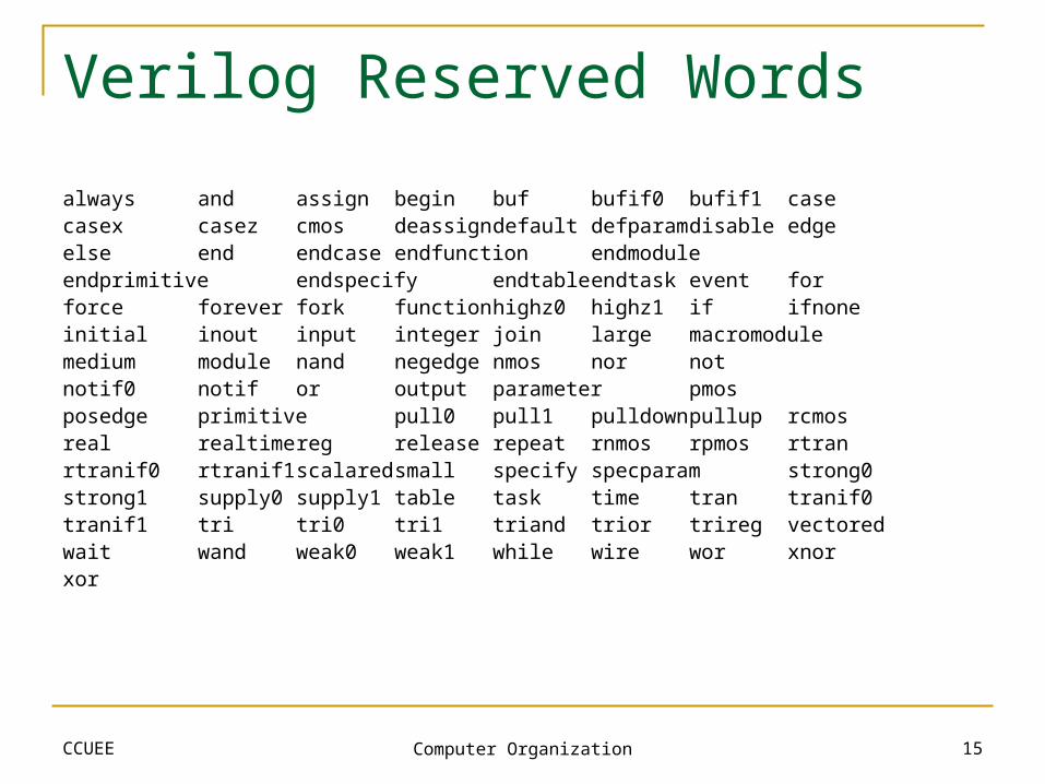
Verilog Reserved Words
always and assign begin buf bufif0 bufif1 casecasex casez cmos deassigndefault defparamdisable edgeelse end endcase endfunction endmoduleendprimitive endspecify endtableendtask event forforce forever fork functionhighz0 highz1 if ifnoneinitial inout input integer join large macromodulemedium module nand negedge nmos nor not notif0 notif or output parameter pmosposedge primitive pull0 pull1 pulldownpullup rcmosreal realtimereg release repeat rnmos rpmos rtranrtranif0 rtranif1scalaredsmall specify specparam strong0strong1 supply0 supply1 table task time tran tranif0tranif1 tri tri0 tri1 triand trior trireg vectoredwait wand weak0 weak1 while wire wor xnorxor

CCUEE Computer Organization 16
Verilog Data Types
Nets - connections between modules input, output ports wires - internal signals Other types: wand, wor, trior, trireg (ignore for now)
Advanced Data Types (more later) Vectors - multiple bit wires, registers, etc. reg - Variables that are assigned values Arrays and Memories Parameters
CCUEE Computer Organization 17
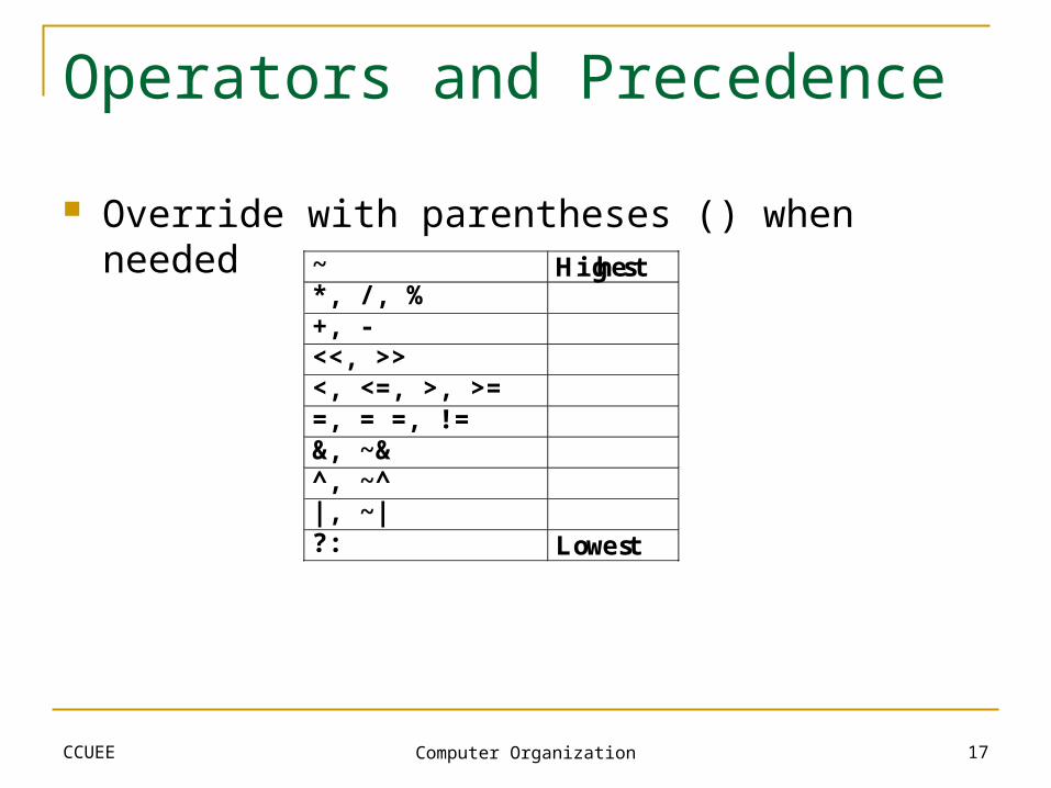
Operators and Precedence
Override with parentheses () when needed~ Highest*, /, %+, -<<, >><, <=, >, >==, = =, !=&, ~&^, ~^|, ~|?: Lowest

CCUEE Computer Organization 18
Modeling with Hierarchy
Create instances of submodules Example: Create a 4-input Mux using mux2 module Original mux2 module:
module mux2(d0, d1, s, y);input [3:0] d0, d1;input s;output [3:0] y;assign y = s ? d1 : d0;
endmodule

CCUEE Computer Organization 19
Modeling with Hierarchy
Create instances of submodules Example: Create a 4-input Mux using mux2 module
module mux4(d0, d1, d2, d3, s, y);input [3:0] d0, d1, d2, d3;input [1:0] s;output [3:0] y;
wire [3:0] low, high;
mux2 lowmux(d0, d1, s[0], low);mux2 highmux(d2, d3, s[0], high);mux2 finalmux(low, high, s[1], y);
endmodule
Instance Names Connections

CCUEE Computer Organization 20
Larger Hierarchy Example
Use full adder to create an n-bit adder
module add8(a, b, sum, cout); input [7:0] a, b; output [7:0] sum; output cout;
wire [7:0] c; // used for carry connections
assign c[0]=0; fulladder f0(a[0], b[0], c[0], sum[0], c[1]); fulladder f1(a[1], b[1], c[1], sum[1], c[2]); fulladder f2(a[2], b[2], c[2], sum[2], c[3]); fulladder f3(a[3], b[3], c[3], sum[3], c[4]); fulladder f4(a[4], b[4], c[4], sum[4], c[5]); fulladder f5(a[5], b[5], c[5], sum[5], c[6]); fulladder f6(a[6], b[6], c[6], sum[6], c[7]); fulladder f7(a[7], b[7], c[7], sum[7], cout);endmodule

CCUEE Computer Organization 21
“Built-In” standard logic gatesand or not xor nand nor xnor
Using Gate Primitives:and g1(y, a, b, c, d);
How are the different from operators (&, |, ~, etc.)? Operators specify function Gate primitives specify structure
OutputInputs (variable number)
Hierarchical Design with Gate Primitives

CCUEE Computer Organization 22
Gate Primitives Example
2-1 Multiplexer
module mux2s(d0, d1, s, y); wire sbar, y0, y1; not inv1(sbar, s); and and1(y0, d0, sbar); and and2(y1, d1, s); or or1(y, y0, y1);endmodule;
Why shouldn’t we use gate primitives? Requires “low-level” implementation decisions It’s often better to let synthesis tools make these

CCUEE Computer Organization 23
Procedural Modeling with always Motivation
assign statements are fine for simple functions More complex functions require procedural modeling
Basic syntax:always @(sensitivity-list)
statement
or
always @(sensitivity-list)
begin
statement-sequence
end
Signal list - change activates block
Procedural statement (=, if/else, etc.)
Compound Statement -sequence of procedural statements

CCUEE Computer Organization 24
Example: 4-input mux behavioral model
module mux4(d0, d1, d2, d3, s, y); input d0, d1, d2, d3; input [1:0] s; output y; reg y;
always @(d0 or d1 or d2 or d3 or s) case (s) 2'd0 : y = d0; 2'd1 : y = d1; 2'd2 : y = d2; 2'd3 : y = d3; default : y = 1'bx; endcaseendmodule
Combinational Modeling with always