Physical Layer Security Made Fast and Channel-Independent Shyamnath Gollakota Dina Katabi.
Upload
harold-littleCategory
view
217download
1
Computer NetworksShyam Gollakota

Computer Networks 2
Administrative• TA: Rajalakshmi Nandakumar ([email protected])
• Course website: cs.washington.edu/561

Computer Networks 3
Course Details• Course material– Mainly research papers with some background
• Prerequisites– Basic math: probability, Fourier, Shortest path alg.

Computer Networks 4
Course Details (2)• Grading– Research Project 50%• Proposal, status report, presentation, final report• OK to combine with other classes, e.g., NLP, Vision
– 1-2 Class Projects 20-30%– One final 20-30%

Computer Networks 5
Class Topics• Wireless Networks
– New perspectives that transcend traditional network stack– Combines signal processing with protocol design
• Mobile Systems– Localization, gesture recognition, RFID, acoustic networking
• Wired Networks– New topics like Data Centers– Traditional Topics: Routing, Resource management

Computer Networks 6
Protocols and Layers• Protocols and layering is the main
structuring method used to divide up network functionality– Each instance of a protocol talks
virtually to its peer using the protocol– Each instance of a protocol uses only
the services of the lower layer

Computer Networks 7
Protocols and Layers (3)• Protocols are horizontal, layers are vertical
X
YY
XInstance of protocol X
Peer instance
Node 1 Node 2
Lower layer instance (of protocol Y)
Protocol X
Service provided by Protocol Y
Computer Networks 8
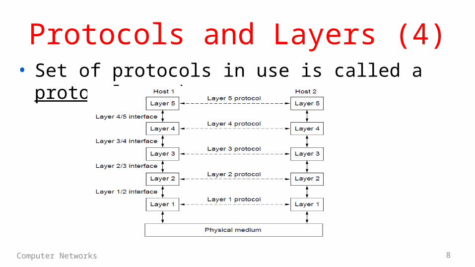
Protocols and Layers (4)• Set of protocols in use is called a protocol stack

Computer Networks 9
Protocols and Layers (6)• Protocols you’ve probably heard of:– TCP, IP, 802.11, Ethernet, HTTP, SSL,
DNS, … and many more
• An example protocol stack– Used by a web browser on a host that
is wirelessly connected to the Internet
HTTP
TCP
IP
802.11
Browser

Computer Networks 10
Encapsulation• Encapsulation is the mechanism
used to effect protocol layering– Lower layer wraps higher layer
content, adding its own information to make a new message for delivery
– Like sending a letter in an envelope; postal service doesn’t look inside

Computer Networks 11
Encapsulation (3)• Message “on the wire” begins to look like an onion– Lower layers are outermost
HTTP
TCP
IP
802.11
HTTP
TCP HTTP
TCP HTTPIP
TCP HTTPIP802.11

Computer Networks 12
Encapsulation (4)HTTP
TCP
IP
802.11
HTTP
TCP HTTP
TCP HTTPIP
TCP HTTPIP802.11
HTTP
TCP
IP
802.11(wire)
HTTP
TCP HTTP
TCP HTTPIP
TCP HTTPIP802.11
TCP HTTPIP802.11

Computer Networks 13
Advantage of Layering• Information hiding and reuse
HTTP
Browser
HTTP
Server
HTTP
Browser
HTTP
Server
or

Computer Networks 14
Advantage of Layering (2)• Information hiding and reuse
HTTP
TCP
IP
802.11
Browser
HTTP
TCP
IP
802.11
Server
HTTP
TCP
IP
Ethernet
Browser
HTTP
TCP
IP
Ethernet
Server
or

Computer Networks 15
Advantage of Layering (3)• Using information hiding to connect different systems
HTTP
TCP
IP
802.11
Browser
HTTP
TCP
IP
Ethernet
Server

Computer Networks 16
Advantage of Layering (4)• Using information hiding to connect different systems
HTTP
TCP
IP
802.11
Browser
IP
802.11
IP
Ethernet
HTTP
TCP
IP
Ethernet
Server
IP TCP HTTP
802.11 IP TCP HTTP Ethernet IP TCP HTTP

Computer Networks 17
Disadvantage of Layering• ??

Computer Networks 18
OSI “7 layer” Reference Model• A principled, international standard, to connect systems– Influential, but not used in practice. (Woops)
– Provides functions needed by users– Converts different representations– Manages task dialogs– Provides end-to-end delivery– Sends packets over multiple links– Sends frames of information– Sends bits as signals

Computer Networks 19
Internet Reference Model• A four layer model based on experience; omits some
OSI layers and uses IP as the network layer.
4 Application – Programs that use network service
3 Transport – Provides end-to-end data delivery
2 Internet – Send packets over multiple networks
1 Link – Send frames over a link

Computer Networks 20
Internet Reference Model (2)• With examples of common protocols in each layer
4 Application3 Transport
2 Internet
1 Link

Computer Networks 21
Internet Reference Model (3)• IP is the “narrow waist” of the Internet– Supports many different links below and apps above
4 Application3 Transport
2 Internet
1 Link Ethernet802.11
IP
TCP UDP
HTTPSMTP RTP DNS
3GDSLCable

Computer Networks 22
Layer-based Names (2)• For devices in the network:
Network
LinkNetwork
Link
Link Link
Physical PhysicalRepeater (or hub)
Switch (or bridge)
Router

Computer Networks 23
Layer-based Names (3)• For devices in the network:
Proxy or middlebox or gateway
Network
LinkNetwork
Link
AppTransport
AppTransport
But they all look like this!

24
Scope of the Physical Layer• Concerns how signals are used to
transfer message bits over a link– Wires etc. carry analog signals– We want to send digital bits
…1011010110…
Signal

25
Simple Link Model• We’ll end with an abstraction of a physical channel
– Rate (or bandwidth, capacity, speed) in bits/second– Delay in seconds, related to length
• Other important properties:– Whether the channel is broadcast, and its error rate
Delay D, Rate R
Message

26
weights of harmonic frequenciesSignal over time
=
Frequency Representation• A signal over time can be represented by its frequency
components (called Fourier analysis)
ampl
itude

27
Lost!
Effect of Less Bandwidth• Fewer frequencies (=less bandwidth) degrades signal
Lost!
Lost!Bandwidth

28
Signals over a Wire• What happens to a signal as it passes over a wire?
1. The signal is delayed (propagates at ⅔c)2. The signal is attenuated (goes for m to km)3. Frequencies above a cutoff are highly attenuated4. Noise is added to the signal (later, causes errors)
EE: Bandwidth = width of frequency band, measured in HzCS: Bandwidth = information carrying capacity, in bits/sec

29
Signals over a Wire (2)• Example:
2: Attenuation:
3: Bandwidth:
4: Noise:
Sent signal

30
Signals over Fiber• Light propagates with very low loss
in three very wide frequency bands– Use a carrier to send information
Wavelength (μm)
Attenuation(dB/km
By SVG: Sassospicco Raster: Alexwind, CC-BY-SA-3.0, via Wikimedia Commons

CSE 461 University of Washington 31
Signals over Wireless• Signals transmitted on a carrier
frequency, like fiber• Travel at speed of light, spread out
and attenuate faster than 1/dist2
• Multiple signals on the same frequency interfere at a receiver

32
Signals over Wireless (5)• Various other effects too!– Wireless propagation is complex,
depends on environment
• Some key effects are highly frequency dependent, – E.g., multipath at microwave
frequencies

33
Wireless Multipath• Signals bounce off objects and take multiple paths– Some frequencies attenuated at receiver, varies with location– Messes up signal; handled with sophisticated methods (§2.5.3)

34
Wireless• Sender radiates signal over a region– In many directions, unlike a wire, to
potentially many receivers– Nearby signals (same freq.) interfere
at a receiver; need to coordinate use

35
WiFi
WiFi

36
Wireless (2)• Microwave, e.g., 3G, and unlicensed (ISM) frequencies,
e.g., WiFi, are widely used for computer networking
802.11b/g/n
802.11a/g/n

37
Topic• We’ve talked about signals
representing bits. How, exactly?– This is the topic of modulation
…1011010110…
Signal

38
A Simple Modulation• Let a high voltage (+V) represent a 1, and low
voltage (-V) represent a 0– This is called NRZ (Non-Return to Zero)
Bits
NRZ
0 0 1 0 1 1 1 1 0 1 0 0 0 0 1 0
+V
-V

39
A Simple Modulation (2)• Let a high voltage (+V) represent a 1, and low
voltage (-V) represent a 0– This is called NRZ (Non-Return to Zero)
Bits
NRZ
0 0 1 0 1 1 1 1 0 1 0 0 0 0 1 0
+V
-V

40
ModulationNRZ signal of bits
Amplitude shift keying
Frequency shift keying
Phase shift keying

41
Topic• How rapidly can we send
information over a link? – Nyquist limit (~1924) »– Shannon capacity (1948) »
• Practical systems are devised to approach these limits

42
Key Channel Properties• The bandwidth (B), signal strength
(S), and noise strength (N)– B limits the rate of transitions– S and N limit how many signal levels
we can distinguish
Bandwidth B Signal S,Noise N

43
Nyquist Limit• The maximum symbol rate is 2B
• Thus if there are V signal levels, ignoring noise, the maximum bit rate is: R = 2B log2V bits/sec
1 0 1 0 1 0 1 0 1 0 1 0 1 0 1 0 1 0 1

44
Claude Shannon (1916-2001)• Father of information theory– “A Mathematical Theory of
Communication”, 1948
• Fundamental contributions to digital computers, security, and communications
Credit: Courtesy MIT Museum
Electromechanical mouse that “solves” mazes!

45
Shannon Capacity• How many levels we can distinguish depends on S/N– Or SNR, the Signal-to-Noise Ratio– Note noise is random, hence some errors
• SNR given on a log-scale in deciBels:– SNRdB = 10log10(S/N)
0
1
2
3
N
S+N

46
Shannon Capacity (2)• Shannon limit is for capacity (C), the
maximum information carrying rate of the channel:
C = B log2(1 + S/N) bits/sec

47
Wired/Wireless Perspective• Wires, and Fiber– Engineer link to have requisite SNR and B→Can fix data rate
• Wireless– Given B, but SNR varies greatly, e.g., up to 60 dB!→Can’t design for worst case, must adapt data rate

48
Wired/Wireless Perspective (2)• Wires, and Fiber– Engineer link to have requisite SNR and B→Can fix data rate
• Wireless– Given B, but SNR varies greatly, e.g., up to 60 dB!→Can’t design for worst case, must adapt data rate
Engineer SNR for data rate
Adapt data rate to SNR

49
Putting it all together – DSL • DSL (Digital Subscriber Line, see §2.6.3) is widely used
for broadband; many variants offer 10s of Mbps– Reuses twisted pair telephone line to the home; it has up to
~2 MHz of bandwidth but uses only the lowest ~4 kHz

50
DSL (2) • DSL uses passband modulation (called OFDM §2.5.1)– Separate bands for upstream and downstream (larger)– Modulation varies both amplitude and phase (called QAM)– High SNR, up to 15 bits/symbol, low SNR only 1 bit/symbol
Upstream Downstream
26 – 138kHz
0-4kHz 143 kHz to 1.1 MHz
Telephone
Freq.
Voice Up to 1 Mbps Up to 12 Mbps
ADSL2: