Computer Hardware Generations - Rochester Institute of...
57
EECC550 - Shaaban EECC550 - Shaaban #1 Lec # 1 Summer2000 6-5-2000 Computer Hardware Generations Computer Hardware Generations • The First Generation, 1946-59: Vacuum Tubes, Relays, Mercury Delay Lines: – ENIAC (Electronic Numerical Integrator and Computer): First electronic computer, 18000 vacuum tubes, 1500 relays, 5000 additions/sec. – First stored program computer: EDSAC (Electronic Delay Storage Automatic Calculator). • The Second Generation, 1959-64: Discrete Transistors. • The Third Generation, 1964-75: Small and Medium-Scale Integrated (MSI) Circuits. • The Fourth Generation, 1975-Present: The Microcomputer. VLSI-based Microprocessors.
Transcript of Computer Hardware Generations - Rochester Institute of...

EECC550 - ShaabanEECC550 - Shaaban#1 Lec # 1 Summer2000 6-5-2000
Computer Hardware GenerationsComputer Hardware Generations• The First Generation, 1946-59: Vacuum Tubes, Relays,
Mercury Delay Lines:– ENIAC (Electronic Numerical Integrator and Computer): First
electronic computer, 18000 vacuum tubes, 1500 relays, 5000additions/sec.
– First stored program computer: EDSAC (Electronic Delay StorageAutomatic Calculator).
• The Second Generation, 1959-64: Discrete Transistors.
• The Third Generation, 1964-75: Small and Medium-ScaleIntegrated (MSI) Circuits.
• The Fourth Generation, 1975-Present: The Microcomputer.VLSI-based Microprocessors.

EECC550 - ShaabanEECC550 - Shaaban#2 Lec # 1 Summer2000 6-5-2000
The Von-The Von-NeumannNeumann Computer Model Computer Model• Partitioning of the computing engine into components:
– Central Processing Unit (CPU): Control Unit (instruction decode, sequencingof operations), Datapath (registers, arithmetic and logic unit, buses).
– Memory: Instruction and operand storage.
– Input/Output (I/O).
– The stored program concept: Instructions from an instruction set arefetched from a common memory and executed one at a time.
-Memory
(instructions, data)
Control
DatapathregistersALU, buses
CPUComputer System
Input
Output
I/O Devices

EECC550 - ShaabanEECC550 - Shaaban#3 Lec # 1 Summer2000 6-5-2000
CPU Machine Instruction Execution StepsCPU Machine Instruction Execution Steps
Instruction
Fetch
Instruction
Decode
Operand
Fetch
Execute
Result
Store
Next
Instruction
Obtain instruction from program storage
Determine required actions and instruction size
Locate and obtain operand data
Compute result value or status
Deposit results in storage for later use
Determine successor or next instruction

EECC550 - ShaabanEECC550 - Shaaban#4 Lec # 1 Summer2000 6-5-2000
Hardware Components of Any ComputerHardware Components of Any Computer
Processor (active)
Computer
ControlUnit
Datapath
Memory(passive)
(where programs, data live whenrunning)
Devices
Input
Output
Keyboard, Mouse, etc.
Display, Printer, etc.
Disk
Five classic components of all computers:Five classic components of all computers:
1. Control Unit; 2. 1. Control Unit; 2. Datapath Datapath; 3. Memory; 4. Input; 5. Output; 3. Memory; 4. Input; 5. Output}
Processor

EECC550 - ShaabanEECC550 - Shaaban#5 Lec # 1 Summer2000 6-5-2000
CPU OrganizationCPU Organization• Datapath Design:
– Capabilities & performance characteristics of principalFunctional Units (FUs):
– (e.g., Registers, ALU, Shifters, Logic Units, ...)
– Ways in which these components are interconnected (busesconnections, multiplexors, etc.).
– How information flows between components.
• Control Unit Design:– Logic and means by which such information flow is controlled.
– Control and coordination of FUs operation to realize the targetedInstruction Set Architecture to be implemented (can either beimplemented using a finite state machine or a microprogram).
• Hardware description with a suitable language, possiblyusing Register Transfer Notation (RTN).

EECC550 - ShaabanEECC550 - Shaaban#6 Lec # 1 Summer2000 6-5-2000
A TypicalA TypicalMicroprocessorMicroprocessorLayout:Layout:
The IntelThe IntelPentium ClassicPentium Classic

EECC550 - ShaabanEECC550 - Shaaban#7 Lec # 1 Summer2000 6-5-2000
A TypicalA TypicalMicroprocessorMicroprocessorLayout:Layout:
The IntelThe IntelPentium ClassicPentium Classic

EECC550 - ShaabanEECC550 - Shaaban#8 Lec # 1 Summer2000 6-5-2000
A Typical PersonalComputer (PC) System BoardLayout (90% of all computingsystems worldwide).
CPU
Memory
I/O: Mass Storage
I/O: Misc
I/O

EECC550 - ShaabanEECC550 - Shaaban#9 Lec # 1 Summer2000 6-5-2000
Computer System ComponentsComputer System Components
Proc
CachesSystem Bus
Memory
I/O Devices:
Controllers
adapters
DisksDisplaysKeyboards
Networks
NICs
I/O Buses

EECC550 - ShaabanEECC550 - Shaaban#10 Lec # 1 Summer2000 6-5-2000
Performance Increase of Workstation-ClassPerformance Increase of Workstation-ClassMicroprocessors 1987-1997Microprocessors 1987-1997
Integer SPEC92 PerformanceInteger SPEC92 Performance

EECC550 - ShaabanEECC550 - Shaaban#11 Lec # 1 Summer2000 6-5-2000
Year
1000
10000
100000
1000000
10000000
100000000
1970 1975 1980 1985 1990 1995 2000
i80386
i4004
i8080
Pentium
i80486
i80286
i8086
Microprocessor Logic DensityMicroprocessor Logic Density
Moore’sMoore’s Law: Law:2X transistors/ChipEvery 1.5 years
Alpha 21264: 15 millionPentium Pro: 5.5 millionPowerPC 620: 6.9 millionAlpha 21164: 9.3 millionSparc Ultra: 5.2 million
Moore’s Law

EECC550 - ShaabanEECC550 - Shaaban#12 Lec # 1 Summer2000 6-5-2000
Increase of Capacity of VLSI Dynamic RAM ChipsIncrease of Capacity of VLSI Dynamic RAM Chips
size
Year
1000
10000
100000
1000000
10000000
100000000
1000000000
1970 1975 1980 1985 1990 1995 2000
year size(Megabit)
1980 0.06251983 0.251986 11989 41992 161996 641999 2562000 1024
1.55X/yr,or doubling every 1.6years

EECC550 - ShaabanEECC550 - Shaaban#13 Lec # 1 Summer2000 6-5-2000
Computer Technology Trends:Computer Technology Trends:
Rapid ChangeRapid Change• Processor:
– 2X in speed every 1.5 years; 1000X performance in last decade.
• Memory:– DRAM capacity: > 2x every 1.5 years; 1000X size in last decade.
– Cost per bit: Improves about 25% per year.
• Disk:– Capacity: > 2X in size every 1.5 years.
– Cost per bit: Improves about 60% per year.
– 200X size in last decade.
• Expected State-of-the-art PC by end of year 2000 :– Processor clock speed: 1500 MegaHertz (1.5 GigaHertz)
– Memory capacity: 500 MegaByte (0.5 GigaBytes)
– Disk capacity: 100 GigaBytes (0.1 TeraBytes)

EECC550 - ShaabanEECC550 - Shaaban#14 Lec # 1 Summer2000 6-5-2000
A Simplified View of TheA Simplified View of TheSoftware/Hardware Hierarchical LayersSoftware/Hardware Hierarchical Layers

EECC550 - ShaabanEECC550 - Shaaban#15 Lec # 1 Summer2000 6-5-2000
Hierarchy of Computer ArchitectureHierarchy of Computer Architecture
I/O systemInstr. Set Proc.
Compiler
OperatingSystem
Application
Digital DesignCircuit Design
Instruction Set Architecture
Firmware
Datapath & Control
Layout
Software
Hardware
Software/Hardware Boundary
High-Level Language Programs
Assembly LanguagePrograms
Microprogram
Register TransferNotation (RTN)
Logic Diagrams
Circuit Diagrams
Machine Language Program
EECC550 - ShaabanEECC550 - Shaaban#16 Lec # 1 Summer2000 6-5-2000
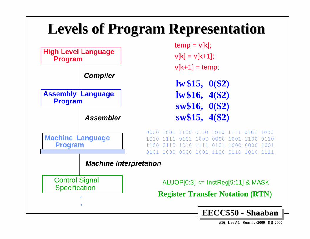
Levels of Program RepresentationLevels of Program RepresentationHigh Level Language
Program
Assembly LanguageProgram
Machine LanguageProgram
Control SignalSpecification
Compiler
Assembler
Machine Interpretation
temp = v[k];
v[k] = v[k+1];
v[k+1] = temp;
lw$15, 0($2)lw$16, 4($2)sw$16, 0($2)sw$15, 4($2)
0000 1001 1100 0110 1010 1111 0101 10001010 1111 0101 1000 0000 1001 1100 0110 1100 0110 1010 1111 0101 1000 0000 1001 0101 1000 0000 1001 1100 0110 1010 1111
°°
ALUOP[0:3] <= InstReg[9:11] & MASK
Register Transfer Notation (RTN)

EECC550 - ShaabanEECC550 - Shaaban#17 Lec # 1 Summer2000 6-5-2000
A Hierarchy of Computer DesignA Hierarchy of Computer DesignLevel Name Modules Primitives Descriptive Media
1 Electronics Gates, FF’s Transistors, Resistors, etc. Circuit Diagrams
2 Logic Registers, ALU’s ... Gates, FF’s …. Logic Diagrams
3 Organization Processors, Memories Registers, ALU’s … Register Transfer
Notation (RTN)
4 Microprogramming Assembly Language Microinstructions Microprogram
5 Assembly language OS Routines Assembly language Assembly Language
programming Instructions Programs
6 Procedural Applications OS Routines High-level Language
Programming Drivers .. High-level Languages Programs
7 Application Systems Procedural Constructs Problem-Oriented
Programs
Low Level - Hardware
Firmware
High Level - Software

EECC550 - ShaabanEECC550 - Shaaban#18 Lec # 1 Summer2000 6-5-2000
Hardware DescriptionHardware Description• Hardware visualization:
– Block diagrams (spatial visualization): Two-dimensional representations of functional units and their
interconnections.– Timing charts (temporal visualization): Waveforms where events are displayed vs. time.
• Register Transfer Notation (RTN):– A way to describe microoperations capable of being performed
by the data flow (data registers, data buses, functional units) atthe register transfer level of design (RT).
– Also describes conditional information in the system whichcause operations to come about.
– A “shorthand” notation for microoperations.
• Hardware Description Languages:– Examples: VHDL: VHSIC (Very High Speed Integrated
Circuits) Hardware Description Language, Verilog.

EECC550 - ShaabanEECC550 - Shaaban#19 Lec # 1 Summer2000 6-5-2000
Register Transfer Notation (RTN)Register Transfer Notation (RTN)• Dependent RTN: When RTN is used after the data flow is
assumed to be frozen. No data transfer can take place over apath that does not exist. No statement implies a function thedata flow hardware is incapable of performing.
• Independent RTN: Describe actions on registers withoutregard to nonexistence of direct paths or intermediateregisters. No predefined data flow.
• The general format of an RTN statement:
Conditional information: Action1; Action2
• The conditional statement is often an AND of literals (statusand control signals) in the system (a p-term). The p-termis said to imply the action.
• Possible actions include transfer of data to/fromregisters/memory data shifting, functional unitoperations etc.

EECC550 - ShaabanEECC550 - Shaaban#20 Lec # 1 Summer2000 6-5-2000
RTN Statement ExamplesRTN Statement ExamplesA ← B
– A copy of the data in entity B (typically a register) isplaced in Register A
– If the destination register has fewer bits than the source,the destination accepts only the lowest-order bits.
– If the destination has more bits than the source, the valueof the source is sign extended to the left.
CTL • T0: A = B– The contents of B are presented to the input of
combinational circuit A
– This action to the right of “:” takes place when controlsignal CTL is active and signal T0 is active.

EECC550 - ShaabanEECC550 - Shaaban#21 Lec # 1 Summer2000 6-5-2000
RTN Statement ExamplesRTN Statement ExamplesMD ← M[MA]
– Memory locations are indicated by square brackets.
– Means the memory data register receives the contents of themain memory (M) as addressed from the Memory Address(MA) register.
AC(0), AC(1), AC(2),AC(3)– Register fields are indicated by parenthesis.
– The concatenation operation is indicated by a comma.
– Bit AC(0) is bit 0 of the accumulator AC
– The above expression means AC bits 0, 1, 2, 3
– More commonly represented by AC(0-3)
E • T3: CLRWRITE– The control signal CLRWRITE is activated when the
condition E • T3 is active.

EECC550 - ShaabanEECC550 - Shaaban#22 Lec # 1 Summer2000 6-5-2000
Computer Architecture Vs. Computer OrganizationComputer Architecture Vs. Computer Organization• The term Computer architecture is sometimes erroneously restricted
to computer instruction set design, with other aspects of computerdesign called implementation.
• More accurate definitions:
– Instruction set architecture: The actual programmer-visibleinstruction set and serves as the boundary between the softwareand hardware.
– Implementation of a machine has two components:
• Organization: includes the high-level aspects of a computer’sdesign such as: The memory system, the bus structure, theinternal CPU unit which includes implementations of arithmetic,logic, branching, and data transfer operations.
• Hardware: Refers to the specifics of the machine such as detailedlogic design and packaging technology.
• In general, Computer Architecture refers to the above three aspects:
1- Instruction set architecture 2- Organization. 3- Hardware.

EECC550 - ShaabanEECC550 - Shaaban#23 Lec # 1 Summer2000 6-5-2000
Instruction Set Architecture (ISA)Instruction Set Architecture (ISA)“... the attributes of a [computing] system as seen by theprogrammer, i.e. the conceptual structure and functionalbehavior, as distinct from the organization of the data flowsand controls the logic design, and the physicalimplementation.” – Amdahl, Blaaw, and Brooks, 1964.
The instruction set architecture is concerned with:
• Organization of programmable storage (memory & registers): Includes the amount of addressable memory and number of available registers.
• Data Types & Data Structures: Encodings & representations.
• Instruction Set: What operations are specified.
• Instruction formats and encoding.
• Modes of addressing and accessing data items and instructions
• Exceptional conditions.

EECC550 - ShaabanEECC550 - Shaaban#24 Lec # 1 Summer2000 6-5-2000
Computer Instruction SetsComputer Instruction Sets• Regardless of computer type, CPU structure, or
hardware organization, every machine instruction mustspecify the following:
– Opcode: Which operation to perform. Example: add,load, and branch.
– Where to find the operand or operands, if any: Operandsmay be contained in CPU registers, main memory, or I/Oports.
– Where to put the result, if there is a result: May beexplicitly mentioned or implicit in the opcode.
– Where to find the next instruction: Without any explicitbranches, the instruction to execute is the next instructionin the sequence or a specified address in case of jump orbranch instructions.
EECC550 - ShaabanEECC550 - Shaaban#25 Lec # 1 Summer2000 6-5-2000
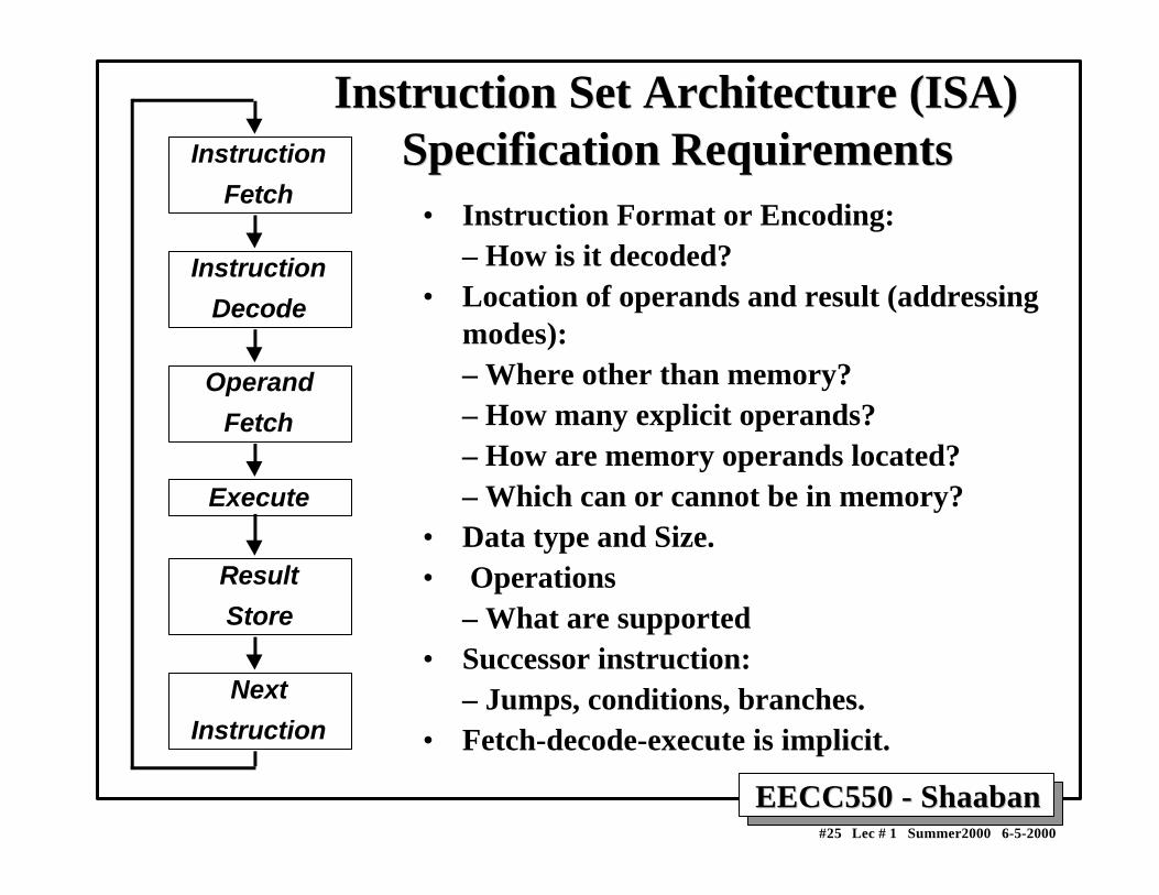
Instruction Set Architecture (ISA)Instruction Set Architecture (ISA)Specification RequirementsSpecification RequirementsInstruction
Fetch
Instruction
Decode
Operand
Fetch
Execute
Result
Store
Next
Instruction
• Instruction Format or Encoding:– How is it decoded?
• Location of operands and result (addressingmodes):– Where other than memory?– How many explicit operands?– How are memory operands located?– Which can or cannot be in memory?
• Data type and Size.• Operations
– What are supported• Successor instruction:
– Jumps, conditions, branches.• Fetch-decode-execute is implicit.

EECC550 - ShaabanEECC550 - Shaaban#26 Lec # 1 Summer2000 6-5-2000
General Types of InstructionsGeneral Types of Instructions• Data Movement Instructions, possible variations:
– Memory-to-memory.
– Memory-to-CPU register.
– CPU-to-memory.
– Constant-to-CPU register.
– CPU-to-output.
– etc.
• Arithmetic Logic Unit (ALU) Instructions.
• Branch Instructions:
– Unconditional.
– Conditional.

EECC550 - ShaabanEECC550 - Shaaban#27 Lec # 1 Summer2000 6-5-2000
Examples of Data Movement InstructionsExamples of Data Movement Instructions
Instruction Meaning Machine
MOV A,B Move 16-bit data from memory loc. A to loc. B VAX11
lwz R3,A Move 32-bit data from memory loc. A to register R3 PPC601
li $3,455 Load the 32-bit integer 455 into register $3 MIPS R3000
MOV AX,BX Move 16-bit data from register BX into register AX Intel X86
LEA.L (A0),A2 Load the address pointed to by A0 into A2 MC68000

EECC550 - ShaabanEECC550 - Shaaban#28 Lec # 1 Summer2000 6-5-2000
Examples of ALU InstructionsExamples of ALU Instructions
Instruction Meaning Machine
MULF A,B,C Multiply the 32-bit floating point values at mem. VAX11locations A and B, and store result in loc. C
nabs r3,r1 Store the negative absolute value of register r1 in r2 PPC601
ori $2,$1,255 Store the logical OR of register $1 with 255 into $2 MIPS R3000
SHL AX,4 Shift the 16-bit value in register AX left by 4 bits Intel X86
ADD.L D0,D1 Add the 32-bit values in registers D0, D1 and store MC68000the result in register D0

EECC550 - ShaabanEECC550 - Shaaban#29 Lec # 1 Summer2000 6-5-2000
Examples of Branch InstructionsExamples of Branch Instructions
Instruction Meaning Machine
BLBS A, Tgt Branch to address Tgt if the least significant bit VAX11at location A is set.
bun r2 Branch to location in r2 if the previous comparison PPC601signaled that one or more values was not a number.
Beq $2,$1,32 Branch to location PC+4+32 if contents of $1 and $2 MIPS R3000are equal.
JCXZ Addr Jump to Addr if contents of register CX = 0. Intel X86
BVS next Branch to next if overflow flag in CC is set. MC68000

EECC550 - ShaabanEECC550 - Shaaban#30 Lec # 1 Summer2000 6-5-2000
Operation Types in The Instruction SetOperation Types in The Instruction Set Operator Type Examples
Arithmetic and logical Integer arithmetic and logical operations: add, or
Data transfer Loads-stores (move on machines with memory
addressing)
Control Branch, jump, procedure call, and return, traps.
System Operating system call, virtual memory management instructions
Floating point Floating point operations: add, multiply.
Decimal Decimal add, decimal multiply, decimal to character conversion
String String move, string compare, string search
Graphics Pixel operations, compression/ decompression operations

EECC550 - ShaabanEECC550 - Shaaban#31 Lec # 1 Summer2000 6-5-2000
Instruction Usage Example:Instruction Usage Example: Top 10 Intel X86 Instructions Top 10 Intel X86 Instructions
Rank Integer Average Percent total executed
1
2
3
4
5
6
7
8
9
10
instruction
load
conditional branch
compare
store
add
and
sub
move register-register
call
return
Total
Observation: Simple instructions dominate instruction usage frequency.
22%
20%
16%
12%
8%
6%
5%
4%
1%
1%
96%

EECC550 - ShaabanEECC550 - Shaaban#32 Lec # 1 Summer2000 6-5-2000
Types of Instruction Set ArchitecturesTypes of Instruction Set ArchitecturesAccording To Operand Addressing FieldsAccording To Operand Addressing Fields
Memory-To-Memory Machines:– Operands obtained from memory and results stored back in memory by any
instruction that requires operands.– No local CPU registers are used in the CPU datapath.– Include:
• The 4 Address Machine.• The 3-address Machine.• The 2-address Machine.
The 1-address (Accumulator) Machine:– A single local CPU special-purpose register (accumulator) is used as the source of
one operand and as the result destination.
The 0-address or Stack Machine:– A push-down stack is used in the CPU.
General Purpose Register (GPR) Machines:– The CPU datapath contains several local general-purpose registers which can be
used as operand sources and as result destinations.– A large number of possible addressing modes.– Load-Store or Register-To-Register Machines: GPR machines where only data
movement instructions (loads, stores) can obtain operands from memory andstore results to memory.

EECC550 - ShaabanEECC550 - Shaaban#33 Lec # 1 Summer2000 6-5-2000
Types of Instruction Set ArchitecturesTypes of Instruction Set Architectures Memory-To-Memory Machines:Memory-To-Memory Machines:
The 4-Address MachineThe 4-Address Machine• No program counter (PC) or other CPU registers are used.• Instructions specify:
– Location of first operand. - Location of second operand.– Place to store the result. - Location of next instruction.
Memory
Op1
Op2
Res
Nexti
::
Op1Addr:
Op2Addr:
ResAddr:
NextiAddr:
+
CPUInstruction:
add Res, Op1, Op2, Nexti
Meaning:
(Res ←← Op1 + Op2)
NextiAddrResAddr Op1Addr Op2Addradd
Bits: 8 24 24 24 24
Instruction Format
Opcode Whichoperation
Where toput result
Where to findnext instruction
Where to find operands

EECC550 - ShaabanEECC550 - Shaaban#34 Lec # 1 Summer2000 6-5-2000
• A program counter is included within the CPU which points to the next instruction.• No CPU storage (general-purpose registers).
Types of Instruction Set ArchitecturesTypes of Instruction Set Architectures Memory-To-Memory Machines:Memory-To-Memory Machines:
The 3-Address MachineThe 3-Address Machine
Instruction:
add Res, Op1, Op2
Meaning:
(Res ← ← Op1 + Op2)
ResAddr Op1Addr Op2Addradd
Bits: 8 24 24 24
Instruction Format
Opcode Whichoperation
Where toput result
Where to find operands
Memory
Op1
Op2
Res
Nexti
::
Op1Addr:
Op2Addr:
ResAddr:
NextiAddr:
+
CPU
ProgramCounter (PC)
Where to findnext instruction
24

EECC550 - ShaabanEECC550 - Shaaban#35 Lec # 1 Summer2000 6-5-2000
• The 2-address Machine: Result is stored in the memory address of one ofthe operands.
Types of Instruction Set ArchitecturesTypes of Instruction Set Architectures Memory-To-Memory Machines:Memory-To-Memory Machines:
The 2-Address MachineThe 2-Address Machine
Instruction:
add Op2, Op1
Meaning:
(Op2 ←← Op1 + Op2)
Where toput result
Op2Addr Op1Addradd
Bits: 8 24 24
Instruction Format
Opcode Whichoperation
Where to find operands
Memory
Op1
Op2,Res
Nexti
::
Op1Addr:
Op2Addr:
NextiAddr:
+
CPU
ProgramCounter (PC)
Where to findnext instruction
24

EECC550 - ShaabanEECC550 - Shaaban#36 Lec # 1 Summer2000 6-5-2000
• A single accumulator in the CPU is used as the source of one operand andresult destination.
Instruction:
add Op1
Meaning:
(Acc ←← Acc + Op1)
Types of Instruction Set ArchitecturesTypes of Instruction Set Architectures The 1-address (Accumulator) MachineThe 1-address (Accumulator) Machine
Op1Addradd
Bits: 8 24
Instruction Format
Opcode Whichoperation
Where to find operand1
Memory
Op1
Nexti
::
Op1Addr:
NextiAddr:
+
CPU
ProgramCounter (PC)
Where to findnext instruction
24
Accumulator
Where to findoperand2, andwhere to put result

EECC550 - ShaabanEECC550 - Shaaban#37 Lec # 1 Summer2000 6-5-2000
• A push-down stack is used in the CPU.
Types of Instruction Set ArchitecturesTypes of Instruction Set Architectures The 0-address (Stack) MachineThe 0-address (Stack) Machine
Instruction: push Op1Meaning: (TOS ←← Op1)
Instruction: addMeaning: (TOS ←← TOS + SOS)
Instruction Format
addBits: 8
Opcode
Instruction: pop ResMeaning: (Res ←← TOS)
Op1AddrpushBits: 8 24
Instruction Format
Opcode Where to find operand
ResAddr popBits: 8 24
Instruction Format
Opcode Memory Destination
CPU
ProgramCounter (PC)
24
Memory
Op1
Nexti
::
Op1Addr:
NextiAddr:
TOS
SOS
etc.
Stackpush
Op2Op2Addr:
ResResAddr:
+
add
Op1
Op2, Respop
8

EECC550 - ShaabanEECC550 - Shaaban#38 Lec # 1 Summer2000 6-5-2000
• CPU contains several general-purpose registers which canbe used as operand sources and result destination.
Types of Instruction Set ArchitecturesTypes of Instruction Set Architectures General Purpose Register (GPR) MachinesGeneral Purpose Register (GPR) Machines
Instruction: load R8, Op1Meaning: (R8 ←← Op1)
+
CPU
ProgramCounter (PC)
24
Memory
Op1
Nexti
::
Op1Addr:
NextiAddr:
R8
R7
R6
R5
R4
R3
R2
R1
Registersload
add
store
Op1AddrloadBits: 8 3 24
Instruction Format
Opcode Where to find operand1
R8
Instruction: add R2, R4, R6Meaning: (R2 ←← R4 + R6)
addBits: 8 3 3 3
Instruction Format
Opcode Des Operands
R2 R4 R6
Instruction: store R2, Op2Meaning: (Op2 ←← R2)
ResAddrstoreBits: 8 3 24
Instruction Format
Opcode Destination
R2

EECC550 - ShaabanEECC550 - Shaaban#39 Lec # 1 Summer2000 6-5-2000
Expression Evaluation Example with 3-, 2-,Expression Evaluation Example with 3-, 2-,1-, 0-Address, And GPR Machines1-, 0-Address, And GPR Machines
For the expression A = (B + C) * D - E where A-E are in memory
0-Address Stack
push B push C add push D mul push E sub pop A
8 instructionsCode size:23 bytes5 memoryaccesses
3-Address
add A, B, Cmul A, A, Dsub A, A, E
3 instructionsCode size:30 bytes9 memory accesses
2-Address
load A, Badd A, Cmul A, Dsub A, E
4 instructionsCode size:28 bytes12 memoryaccesses
1-AddressAccumulator
load B add C mul D sub E store A
5 instructionsCode size:20 bytes5 memory accesses
GPRRegister-Memory
load R1, B add R1, C mul R1, D sub R1, E store A, R1
5 instructions Code size: about 22 bytes 5 memory accesses
Load-Store
load R1, Bload R2, Cadd R3, R1, R2load R1, Dmul R3, R3, R1load R1, Esub R3, R3, R1store A, R3
8 instructions Code size: about 29 bytes 5 memory accesses

EECC550 - ShaabanEECC550 - Shaaban#40 Lec # 1 Summer2000 6-5-2000
Typical ISA Addressing ModesTypical ISA Addressing Modes
Register
Immediate
Displacement
Indirect
Indexed
Absolute
Memory indirect
Autoincrement
Autodecrement
Scaled
R4 ← R4 + R3
R4 ← R4 + 3
R4 ← R4 + Mem[10+ R1]
R4 ← R4 + Mem[R1]
R3 ← R3 +Mem[R1 + R2]
R1 ← R1 + Mem[1001]
R1 ← R1 + Mem[Mem[R3]]
R1 ← R1 + Mem[R2]
R2 ← R2 + d
R2 ← R2 - d
R1 ← R1 + Mem[R2]
R1 ← R1+ Mem[100+ R2 + R3*d]
Add R4, R3
Add R4, #3
Add R4, 10 (R1)
Add R4, (R1)
Add R3, (R1 + R2)
Add R1, (1001)
Add R1, @ (R3)
Add R1, (R2) +
Add R1, - (R2)
Add R1, 100 (R2) [R3]
Addressing Sample Mode Instruction Meaning

EECC550 - ShaabanEECC550 - Shaaban#41 Lec # 1 Summer2000 6-5-2000
Addressing Modes Usage ExampleAddressing Modes Usage Example
Displacement 42% avg, 32% to 55%
Immediate: 33% avg, 17% to 43%
Register deferred (indirect): 13% avg, 3% to 24%
Scaled: 7% avg, 0% to 16%
Memory indirect: 3% avg, 1% to 6%
Misc: 2% avg, 0% to 3%
75% displacement & immediate88% displacement, immediate & register indirect.
Observation: In addition Register direct, Displacement,Immediate, Register Indirect addressing modes are important.
For 3 programs running on VAX ignoring direct register mode:
75%88%

EECC550 - ShaabanEECC550 - Shaaban#42 Lec # 1 Summer2000 6-5-2000
Displacement Address Size ExampleDisplacement Address Size ExampleAvg. of 5 SPECint92 programs v. avg. 5 SPECfp92 programs
1% of addresses > 16-bits
12 - 16 bits of displacement needed
0%
10%
20%
30%
0 1 2 3 4 5 6 7 8 9
10 11 12 13 14 15
Int. Avg. FP Avg.
Displacement Address Bits Needed

EECC550 - ShaabanEECC550 - Shaaban#43 Lec # 1 Summer2000 6-5-2000
Instruction Set EncodingInstruction Set EncodingConsiderations affecting instruction set encoding:
– To have as many registers and addressing modes aspossible.
– The Impact of of the size of the register and addressingmode fields on the average instruction size and on theaverage program.
– To encode instructions into lengths that will be easy tohandle in the implementation. On a minimum to bea multiple of bytes.
• Fixed length encoding: Faster and easiest to implement inhardware.
• Variable length encoding: Produces smaller instructions.
• Hybrid encoding.

EECC550 - ShaabanEECC550 - Shaaban#44 Lec # 1 Summer2000 6-5-2000
Three Examples of Instruction Set EncodingThree Examples of Instruction Set Encoding
Variable Length Encoding: VAX (1-53 bytes)
Operations &no of operands
Addressspecifier 1
Addressfield 1
Address specifier n
Address field n
Operation Addressfield 1
Addressfield 2
Addressfield3
Fixed Length Encoding: DLX, MIPS, PowerPC, SPARC
Operation Address Specifier
Addressfield
Operation AddressSpecifier 1
AddressSpecifier 2
Address field
OperationAddress Specifier Address
field 1
Address field 2
Hybrid Encoding: IBM 360/370, Intel 80x86

EECC550 - ShaabanEECC550 - Shaaban#45 Lec # 1 Summer2000 6-5-2000
Instruction Set Architecture Trade-Instruction Set Architecture Trade-offsoffs• 3-address machine: shortest code sequence; a large number of
bits per instruction; large number of memory accesses.
• 0-address (stack) machine: Longest code sequence; shortestindividual instructions; more complex to program.
• General purpose register machine (GPR):– Addressing modified by specifying among a small set of
registers with using a short register address (all machinessince 1975).
– Advantages of GPR:• Low number of memory accesses. Faster, since register access
is currently still much faster than memory access.• Registers are easier for compilers to use.• Shorter, simpler instructions.
• Load-Store Machines: GPR machines where memory addressesare only included in data movement instructions between memoryand registers (all machines after 1980).

EECC550 - ShaabanEECC550 - Shaaban#46 Lec # 1 Summer2000 6-5-2000
ISA ExamplesISA Examples Machine Number of General Architecture year
Purpose Registers
EDSAC
IBM 701
CDC 6600
IBM 360
DEC PDP-11
DEC VAX
Motorola 68000
MIPS
SPARC
1
1
8
16
8
16
16
32
32
accumulator
accumulator
load-store
register-memory
register-memory
register-memorymemory-memory
register-memory
load-store
load-store
1949
1953
1963
1964
1970
1977
1980
1985
1987

EECC550 - ShaabanEECC550 - Shaaban#47 Lec # 1 Summer2000 6-5-2000
Examples of GPR MachinesExamples of GPR Machines
Number ofNumber of Maximum numberMaximum number
memory addresses of operands allowedmemory addresses of operands allowed
SPARK, MIPSSPARK, MIPS
PowerPC, ALPHA PowerPC, ALPHA
Intel 80x86,Intel 80x86,
Motorola 68000 Motorola 68000
2 or 3 2 or 3 VAXVAX
0 3
1 2

EECC550 - ShaabanEECC550 - Shaaban#48 Lec # 1 Summer2000 6-5-2000
Complex Instruction Set Computer (CISC)Complex Instruction Set Computer (CISC)• Emphasizes doing more with each instruction.
• Motivated by the high cost of memory and hard diskcapacity when original CISC architectures were proposed:– When M6800 was introduced: 16K RAM = $500, 40M hard disk = $ 55, 000
– When MC68000 was introduced: 64K RAM = $200, 10M HD = $5,000
• Original CISC architectures evolved with faster, morecomplex CPU designs, but backward instruction setcompatibility had to be maintained.
• Wide variety of addressing modes:• 14 in MC68000, 25 in MC68020
• A number instruction modes for the location and number ofoperands:
• The VAX has 0- through 3-address instructions.
• Variable-length or hybrid instruction encoding is used.

EECC550 - ShaabanEECC550 - Shaaban#49 Lec # 1 Summer2000 6-5-2000
Example CISC Example CISC ISAsISAs Motorola 680X0Motorola 680X0
18 addressing modes:• Data register direct.• Address register direct.• Immediate.• Absolute short.• Absolute long.• Address register indirect.• Address register indirect with postincrement.• Address register indirect with predecrement.• Address register indirect with displacement.• Address register indirect with index (8-bit).• Address register indirect with index (base).• Memory inderect postindexed.• Memory indirect preindexed.• Program counter indirect with index (8-bit).• Program counter indirect with index (base).• Program counter indirect with displacement.• Program counter memory indirect postindexed.• Program counter memory indirect preindexed.
Operand size:• Range from 1 to 32 bits, 1, 2, 4, 8,
10, or 16 bytes.
Instruction Encoding:• Instructions are stored in 16-bit
words.
• the smallest instruction is 2- bytes(one word).
• The longest instruction is 5 words(10 bytes) in length.

EECC550 - ShaabanEECC550 - Shaaban#50 Lec # 1 Summer2000 6-5-2000
Example CISC ISA:Example CISC ISA:
Intel X86, 386/486/PentiumIntel X86, 386/486/Pentium12 addressing modes:
• Register.
• Immediate.
• Direct.
• Base.
• Base + Displacement.
• Index + Displacement.
• Scaled Index + Displacement.
• Based Index.
• Based Scaled Index.
• Based Index + Displacement.
• Based Scaled Index + Displacement.
• Relative.
Operand sizes:• Can be 8, 16, 32, 48, 64, or 80 bits long.
• Also supports string operations.
Instruction Encoding:• The smallest instruction is one byte.
• The longest instruction is 12 bytes long.
• The first bytes generally contain the opcode,mode specifiers, and register fields.
• The remainder bytes are for addressdisplacement and immediate data.

EECC550 - ShaabanEECC550 - Shaaban#51 Lec # 1 Summer2000 6-5-2000
Reduced Instruction Set Computer (RISC)Reduced Instruction Set Computer (RISC)• Focuses on reducing the number and complexity of
instructions of the machine.
• Reduced number of cycles needed per instruction.– Goal: At least one instruction completed per clock cycle.
• Designed with CPU instruction pipelining in mind.
• Fixed-length instruction encoding.
• Only load and store instructions access memory.
• Simplified addressing modes.– Usually limited to immediate, register indirect, register
displacement, indexed.
• Delayed loads and branches.
• Prefetch and speculative execution.
• Examples: MIPS, HP-PA, UltraSpark, Alpha, PowerPC.

EECC550 - ShaabanEECC550 - Shaaban#52 Lec # 1 Summer2000 6-5-2000
Example RISC ISA:Example RISC ISA:
PowerPCPowerPC8 addressing modes:
• Register direct.
• Immediate.
• Register indirect.
• Register indirect with immediateindex (loads and stores).
• Register indirect with register index(loads and stores).
• Absolute (jumps).
• Link register indirect (calls).
• Count register indirect (branches).
Operand sizes:• Four operand sizes: 1, 2, 4 or 8 bytes.
Instruction Encoding:• Instruction set has 15 different formats
with many minor variations.•
• All are 32 bits in length.

EECC550 - ShaabanEECC550 - Shaaban#53 Lec # 1 Summer2000 6-5-2000
Example RISC ISA:Example RISC ISA:
HP Precision Architecture, HP-PA HP Precision Architecture, HP-PA
7 addressing modes:• Register
• Immediate
• Base with displacement
• Base with scaled index anddisplacement
• Predecrement
• Postincrement
• PC-relative
Operand sizes:• Five operand sizes ranging in powers of
two from 1 to 16 bytes.
Instruction Encoding:• Instruction set has 12 different formats.•
• All are 32 bits in length.

EECC550 - ShaabanEECC550 - Shaaban#54 Lec # 1 Summer2000 6-5-2000
Example RISC ISA:Example RISC ISA:
SPARCSPARC
5 addressing modes:• Register indirect with immediate
displacement.
• Register inderect indexed by anotherregister.
• Register direct.
• Immediate.
• PC relative.
Operand sizes:• Four operand sizes: 1, 2, 4 or 8 bytes.
Instruction Encoding:• Instruction set has 3 basic instruction
formats with 3 minor variations.
• All are 32 bits in length.

EECC550 - ShaabanEECC550 - Shaaban#55 Lec # 1 Summer2000 6-5-2000
Example RISC ISA:Example RISC ISA:
DEC/Compaq Alpha AXPDEC/Compaq Alpha AXP
4 addressing modes:• Register direct.
• Immediate.
• Register indirect with displacement.
• PC-relative.
Operand sizes:• Four operand sizes: 1, 2, 4 or 8 bytes.
Instruction Encoding:• Instruction set has 7 different formats.•
• All are 32 bits in length.

EECC550 - ShaabanEECC550 - Shaaban#56 Lec # 1 Summer2000 6-5-2000
RISC ISA Example:RISC ISA Example:
MIPS R3000MIPS R3000Instruction Categories:
• Load/Store.• Computational.• Jump and Branch.• Floating Point (using coprocessor).• Memory Management.• Special.
OP
OP
OP
rs rt rd sa funct
rs rt immediate
jump target
Instruction Encoding: 3 Instruction Formats, all 32 bits wide.
R0 - R31
PCHI
LO
Registers 4 Addressing Modes:• Base register + immediate offset
(loads and stores).
• Register direct (arithmetic).
• Immedate (jumps).
• PC relative (branches).
Operand Sizes:• Memory accesses in any
multiple between 1 and 8 bytes.

EECC550 - ShaabanEECC550 - Shaaban#57 Lec # 1 Summer2000 6-5-2000
Evolution of Instruction Set ArchitecturesEvolution of Instruction Set ArchitecturesSingle Accumulator (EDSAC 1950)
Accumulator + Index Registers(Manchester Mark I, IBM 700 series 1953)
Separation of Programming Model from Implementation
High-level Language Based Concept of an ISA Family(B5000 1963) (IBM 360 1964)
General Purpose Register (GPR) Machines
Complex Instruction Sets (CISC) Load/Store Architecture
RISC
(Vax, Motorola 68000, Intel x86 1977-80) (CDC 6600, Cray 1 1963-76)
(MIPS, SPARC, HP-PA, IBM RS6000, . . . 1987)