COMPUTER GRAPHICS OPTIQUE Optical Superposition …majumder/docs/CGO01.pdf · COMPUTER GRAPHICS...
9
COMPUTER GRAPHICS OPTIQUE Optical Superposition of Projected Computer Graphics Aditi Majumder and Greg Welch Department of Computer Science, University of North Carolina at Chapel Hill, NC, USA majumder,welch @cs.unc.edu Abstract. We present some ideas and demonstrations for a hybrid projector- based rendering and display technique we call Computer Graphics Optique. In- stead of partially overlapping projected images to achieve a wide-area display, we completely overlap projected images on top of each other to achieve the addition of light and color in an “optical composition buffer.” The idea is to use the optical composition to replace some analytical computation, to increase rendering speed, gain flexibility, intensity range, and intensity resolution. In addition one can make use of electronic and optical projector controls such as focus augmented with the optical superposition to achieve effects that are otherwise computationally expen- sive. We believe that this technique offers the possibility of a new paradigm for combined rendering and projector-based display. 1 Introduction Light projectors have been used in computer graphics for almost as long as graphics has been around. During all of this time they have been used almost exclusively to construct wide-area and high-resolution tiled displays [17, 7, 10, 15, 13]. A typical design goal for such systems is to maximize the usable display area, and so overlap between projectors is minimized. Recently however we wondered what might be gained by maximizing the overlap between multiple projectors—that is, by “stacking” or superimposing the projector images on top of each other to achieve addition of light and color optically. For example, this optical superposition certainly yields brighter displays. Taking advantage of this property, many popular projector vendors like Sony, Panasonic, Ep- son and others are now providing features to ‘stack’ 2-3 projectors to achieve two or three times brighter images. They are also providing lens shift controls to facilitate the alignment of imagery from multiple projectors right on top of each other. It appears that optical superposition of imagery was being done in a limited fashion even a century ago. In 1888 Emile Reynaud created a machine called Theatre Optique (Figure 1), a revised version of his earlier invention the praxinoscope. In Theatre Op- tique a subsidiary light called “magic lantern,” was used to project a stationary back- ground on the same screen where the action film was projected. In more recent times, the flight simulator community used a similar method called calligraphic lights to su- perimpose high intensity and brighter runway lights on a projected scene. Beyond increased brightness, we believe optical superposition augmented by some optical effects like blurring (available in most projectors), can be used in modern com- puter graphics to replace expensive computation, to increase rendering speed, to achieve
Transcript of COMPUTER GRAPHICS OPTIQUE Optical Superposition …majumder/docs/CGO01.pdf · COMPUTER GRAPHICS...
COMPUTER GRAPHICS OPTIQUEOptical Superposition of Projected Computer Graphics
Aditi Majumder and Greg Welch
Department of Computer Science,University of North Carolina at Chapel Hill, NC, USA
fmajumder,[email protected]
Abstract. We present some ideas and demonstrations for a hybrid projector-based rendering and display technique we callComputer Graphics Optique. In-stead of partially overlapping projected images to achieve a wide-area display, wecompletely overlap projected images on top of each other to achieve the additionof light and color in an “optical composition buffer.” The idea is to use the opticalcomposition to replace some analytical computation, to increase rendering speed,gain flexibility, intensity range, and intensity resolution. In addition one can makeuse of electronic and optical projector controls such as focus augmented with theoptical superposition to achieve effects that are otherwise computationally expen-sive. We believe that this technique offers the possibility of a new paradigm forcombined rendering and projector-based display.
1 Introduction
Light projectors have been used in computer graphics for almost as long as graphics hasbeen around. During all of this time they have been used almost exclusively to constructwide-area and high-resolution tiled displays [17, 7, 10, 15, 13]. A typical design goal forsuch systems is to maximize the usable display area, and so overlap between projectorsis minimized. Recently however we wondered what might be gained bymaximizingthe overlap between multiple projectors—that is, by “stacking” orsuperimposing theprojector images on top of each other to achieve addition of light and coloroptically.
For example, this optical superposition certainly yields brighter displays. Takingadvantage of this property, many popular projector vendors like Sony, Panasonic, Ep-son and others are now providing features to ‘stack’ 2-3 projectors to achieve two orthree times brighter images. They are also providing lens shift controls to facilitate thealignment of imagery from multiple projectors right on top of each other.
It appears that optical superposition of imagery was being done in a limited fashioneven a century ago. In 1888 Emile Reynaud created a machine calledTheatre Optique(Figure 1), a revised version of his earlier invention thepraxinoscope. In Theatre Op-tique a subsidiary light called “magic lantern,” was used to project a stationary back-ground on the same screen where the action film was projected. In more recent times,the flight simulator community used a similar method calledcalligraphic lights to su-perimpose high intensity and brighter runway lights on a projected scene.
Beyond increased brightness, we believe optical superposition augmented by someoptical effects like blurring (available in most projectors), can be used in modern com-puter graphics to replace expensivecomputation, to increase renderingspeed, to achieve
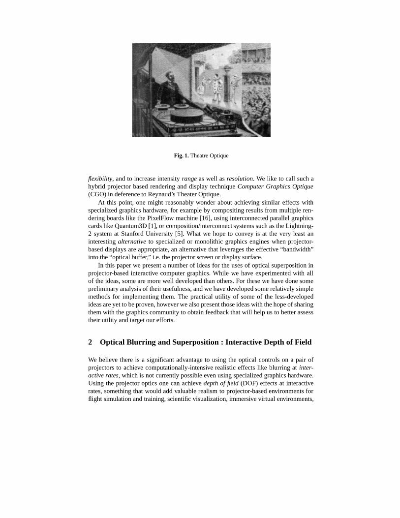
Fig. 1. Theatre Optique
flexibility, and to increase intensityrange as well asresolution. We like to call such ahybrid projector based rendering and display techniqueComputer Graphics Optique(CGO) in deference to Reynaud’s Theater Optique.
At this point, one might reasonably wonder about achieving similar effects withspecialized graphics hardware, for example by compositing results from multiple ren-dering boards like the PixelFlow machine [16], using interconnected parallel graphicscards like Quantum3D [1], or composition/interconnect systems such as the Lightning-2 system at Stanford University [5]. What we hope to convey is at the very least aninterestingalternative to specialized or monolithic graphics engines when projector-based displays are appropriate, an alternative that leverages the effective “bandwidth”into the “optical buffer,” i.e. the projector screen or display surface.
In this paper we present a number of ideas for the uses of optical superposition inprojector-based interactive computer graphics. While we have experimented with allof the ideas, some are more well developed than others. For these we have done somepreliminary analysis of their usefulness, and we have developed some relatively simplemethods for implementing them. The practical utility of some of the less-developedideas are yet to be proven, however we also present those ideas with the hope of sharingthem with the graphics community to obtain feedback that will help us to better assesstheir utility and target our efforts.
2 Optical Blurring and Superposition : Interactive Depth of Field
We believe there is a significant advantage to using the optical controls on a pair ofprojectors to achieve computationally-intensive realistic effects like blurring atinter-active rates, which is not currently possible even using specialized graphics hardware.Using the projector optics one can achievedepth of field (DOF) effects at interactiverates, something that would add valuable realism to projector-based environments forflight simulation and training, scientific visualization, immersive virtual environments,
architectural walkthroughs, and entertainment. Beyond a lack of realism, the absenseof DOF effects leads to eye strain asfusion stimuli are generated for objects outsidethe limited depth of focus of the eye. DOF effects are also sometimes used as depthcues. For example for night-vision training of helicopter pilots, pilots rely on DOF cuesnear the ground to compensate for the narrow fields of view of night vision goggles. Bysome simple experiments, we demonstrate how optical blurring and superposition canbe used to achieve a DOF effect in real-time.
2.1 Algorithm
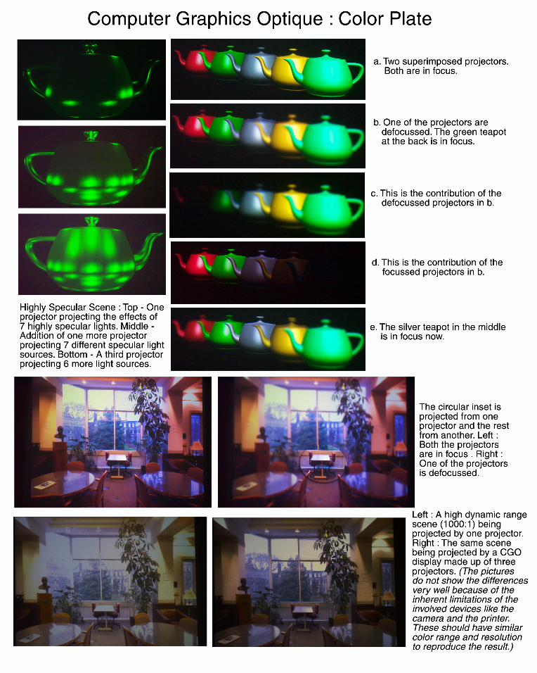
We use two projectors whose images overlap completely. We designate one projector asthefocused projector and the other as thedefocused projector. We then adjust the opticalfocus of the latter to correspond to the maximum circle of confusion for the applica-tion. At run-time we use a two pass rendering approach. After the image is renderedby the traditional graphics pipeline in the first pass, each pixel is divided into two com-plementary components based on its distance from the focal plane in the second pass.Thus we get two images: one to be sent to the focused projector, and the other to thedefocused projector. When projected, the two overlapping images combine via opticalsuperposition, resulting in a single image with depth-dependent blur (Color Plate).
In effect we use the projector optics to perform two samples of the image convo-lution, and then we use optical superposition to blend a weighted combination of theresults. We can vary the depth of the focal plane in real time. One could do so basedon a user’s head position for example, or ideally (if available) eye tracking could beemployed [18] to adjust the focal plane.
We can use a similar technique to achieve a focused inset region in a blurred 2Dimage (or visa versa). We use a focused projector to render the inset region, and adefocused projector to render the rest. We can move the focused inset around in theimage interactively by moving a pattern in the alpha buffers (Color Plate).
2.2 Analysis
Now, we will analyse what we are actually getting using this method and how similar itis to the ideal depth of field effect.
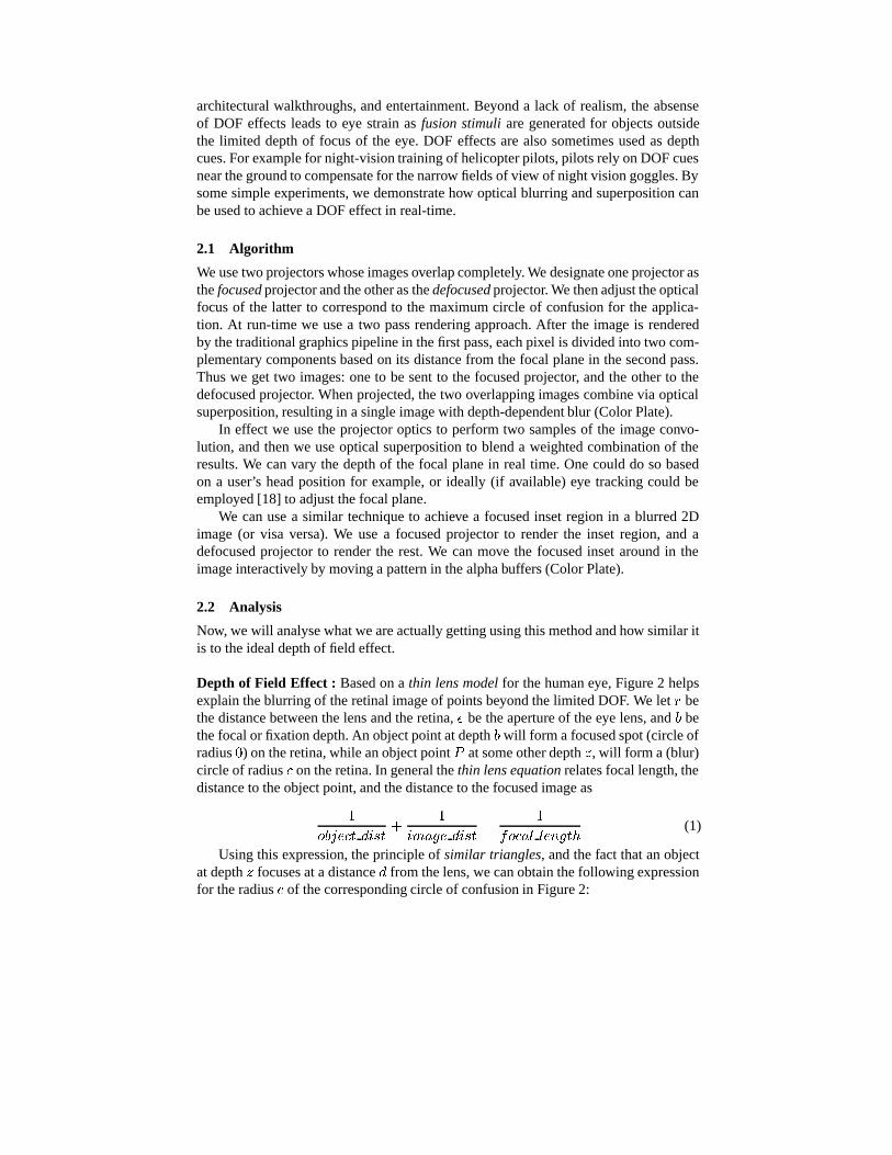
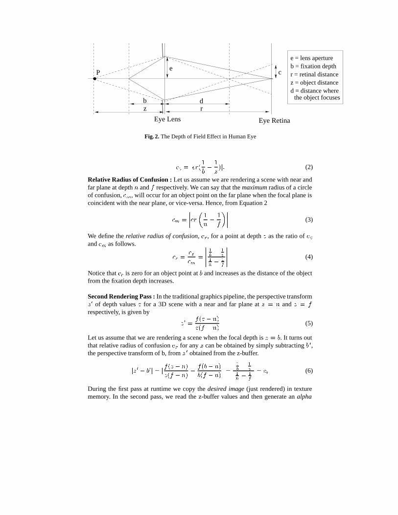
Depth of Field Effect : Based on athin lens model for the human eye, Figure 2 helpsexplain the blurring of the retinal image of points beyond the limited DOF. We letr bethe distance between the lens and the retina,e be the aperture of the eye lens, andb bethe focal or fixation depth. An object point at depthb will form a focused spot (circle ofradius0) on the retina, while an object pointP at some other depthz, will form a (blur)circle of radiusc on the retina. In general thethin lens equation relates focal length, thedistance to the object point, and the distance to the focused image as
1
object dist+
1
image dist=
1
focal length(1)
Using this expression, the principle ofsimilar triangles, and the fact that an objectat depthz focuses at a distanced from the lens, we can obtain the following expressionfor the radiusc of the corresponding circle of confusion in Figure 2:
bz r
d
ce
Eye RetinaEye Lens
e = lens apertureb = fixation depthr = retinal distancez = object distance
P
d = distance where the object focuses
Fig. 2. The Depth of Field Effect in Human Eye
cz = jer(1
b�
1
z)j: (2)
Relative Radius of Confusion : Let us assume we are rendering a scene with near andfar plane at depthn andf respectively. We can say that themaximum radius of a circleof confusion,cm, will occur for an object point on the far plane when the focal plane iscoincident with the near plane, or vice-versa. Hence, from Equation 2
cm =
����er�1
n�
1
f
����� (3)
We define therelative radius of confusion, cr, for a point at depthz as the ratio ofczandcm as follows.
cr =cz
cm=
�����1
b� 1
z
1
n� 1
f
����� (4)
Notice thatcr is zero for an object point atb and increases as the distance of the objectfrom the fixation depth increases.
Second Rendering Pass : In the traditional graphics pipeline, the perspective transformz0 of depth valuesz for a 3D scene with a near and far plane atz = n andz = f
respectively, is given by
z0 =
f(z � n)
z(f � n)(5)
Let us assume that we are rendering a scene when the focal depth isz = b. It turns outthat relative radius of confusioncr for anyz can be obtained by simply subtractingb 0,the perspective transform of b, fromz 0 obtained from the z-buffer.
jz0 � b0j = j
f(z � n)
z(f � n)�
f(b� n)
b(f � n)j =
j 1b� 1
zj
j 1n� 1
fj= cr (6)
During the first pass at runtime we copy thedesired image (just rendered) in texturememory. In the second pass, we read the z-buffer values and then generate analpha
mask for the defocused projector by calculating thec r at every pixel by subtractingb0
from the values read from the z-buffer. We simultaneously generate a complementaryalpha mask for the focused projector. Finally we usealpha blending and texture mapthe desired image on the projector’s image plane using the respective alpha masks.
Summary : Thus, an ideal DOF effect is generated in a graphics systems by blurringeach pixel by their relative radius of confusion. However, our method achieves thiseffect by the constant radius of confusion produced by the defocussed projector whilelimiting the amount of light from the defocussed projector to be proportional to therelative radius of confusion. The rest of the light comes from the focussed projectorwith the hope that this will perceptually create a circle of confusion equivalent to theideal one.
3 Optical Superposition : Parallelism and Flexibility in Rendering
Wile conventional graphics hardware has achieved significant performance in the years,it has done so while effectively restricting interactive computer graphics to specializedAPIs and rendering paradigms. It is currently difficult, if not impossible, to match andmix between different rendering styles while rendering the same scene. We believe thatoptical superposition has the potential to liberate us from this rigidity and give us a newflexibility to simultaneously combine rendering methods for the same imagery. Evenfor one or more similar rendering methods the technique could potentially be used toexploit parallelism, improving rendering speed by sharing tasks between independent“optical pipelines.”
Separating Lighting Components : One universal aspect of computer graphics wheresuperposition inherently plays a fundamental role is virtual scene illumination. Such il-lumination is typically modeled as a sum of independent terms that are added together.Separating these components offers the flexibility of using different lighting effects inparallel for the same scene. For example, we can optically combine diffuse lighting froma global illumination algorithm with specular lighting from a simple Phong model. Asa proof of concept, we compute the diffuse and specular lighting using two differentgraphics pipeline, and project the images asynchronously on top of each other fromtwo different projectors. One might extend this to separate lighting into different spatialregions and resolutions also. For example, lower resolution computation and projectorsfor ambient or diffuse lighting, and higher resolution for specular effects or hard shad-ows.
Stages in Graphics Pipeline : There is often no reason for texture mapping to be cou-pled to lighting, which normally depends only on the surface normal and material prop-erties. In some cases each could be computed with a different platform or pipeline, andprojected asynchronously.
Multi-Pass Rendering : Many algorithms have multiple rendering passes which are in-dependent of each other, and theaccumulation buffer [9] is used to add colors. All such
algorithms can have their different rendering passes implemented in multiple graphicspipeline in parallel, each being output to a projector, and the results can be combined inanoptical accumulation buffer. For example, Diefenbach achieves effects like shadows,reflections and refractions in [4] using an accumulation buffer and a multi-pass render-ing method. Or, for example, sometimes software and computational resources placepractical limits on the number of lights that can be used in a scene (OpenGL is lim-ited to eight lights). Thus an interactive ray-traced scene with 50 lights would probablytake multiple rendering passes. Here also, we can render subsets of lights in parallel onseparate graphics pipelines, and then optically combine the (projected) results (ColorPlate) to achieve highly specular and photorealistic scenes without compromising onthe interactive rates.
4 Optical Superposition : Higher-Fidelity Imagery
The color range in conventional graphics ranges only from0� 255. Here we show thata display made up of superimposed images from multiple projectors is not only brighterbut has a higher intensity resolution which can be used to render outdoor/natural scenesmore realistically.
A displayd capable of producing a lowest intensityI(0) = L (the black level) andhighest intensityI(n� 1) = H (the white level), is characterized by the following.
– Range: The difference between the highest and the lowest intensity levels,H � L.– Dynamic Range: The ratio of the highest and lowest intensities,H
L.
– Thenumber of levels, n, between the highest and lowest intensities, which is typi-cally 256. This is the number of unique discrete colors that can be produced.
– Intensity Resolution: Levels per unit intensity, n
H�L. This is true only for devices
with a linear response. Thus, we assume that all our projectors have been correctedfor different kind of non-linearities [10].
With the use of multiple overlapping projectors, therange is the sum of the indi-vidual projector ranges. Thedynamic range is approximately the same as that of theindividual projectors. It can be shown that a CGO display made up ofm projectorseach havingn discrete intensity levels can have a minimum ofO(mn) and a maximumof O(nm) discrete intensity levels. As a result, we get a higherintensity resolution froma CGO display.
The number of levels (n) that is sufficient for amonochrome display is given by1:01 = (H=L)1=n [8]. Based on the response curves of multiple projectors [11] wefind thatn = 500 would be sufficient for a monochrome projector. Further, [19] saysthat humans are3� 4 times more sensitive to luminance differences in the presence ofcolor. Thus, the problems arising from the low value ofn offered by current projectorscan be addressed to some extent by CGO. Further, the larger range will result in higherquality images. We demonstrate this by using three overlapped projectors to render ahigh dynamic range scene (Color Plate).
5 Limitations
The CGO idea is not without limitations. The most significant limitation is that it is onlyuseful when a projector-based display is appropriate. Further, since today’s projectorsdo not produce zero intensity for a corresponding zero input, optical superposition in-creases perceived “black level.” However, it is reasonable to expect this to improvewith new technology [6]. A potential limitation when using CGO with parallel opti-cal pipelines is that one might need to explicitly manage certain occlusions, instead ofrelying on the hardware to resolve them. Finally, while there may be concerns aboutluminance/color uniformity and geometric blending issues, we have used the methodsof [11] to achieve results that are comparable to a single-projector setup.
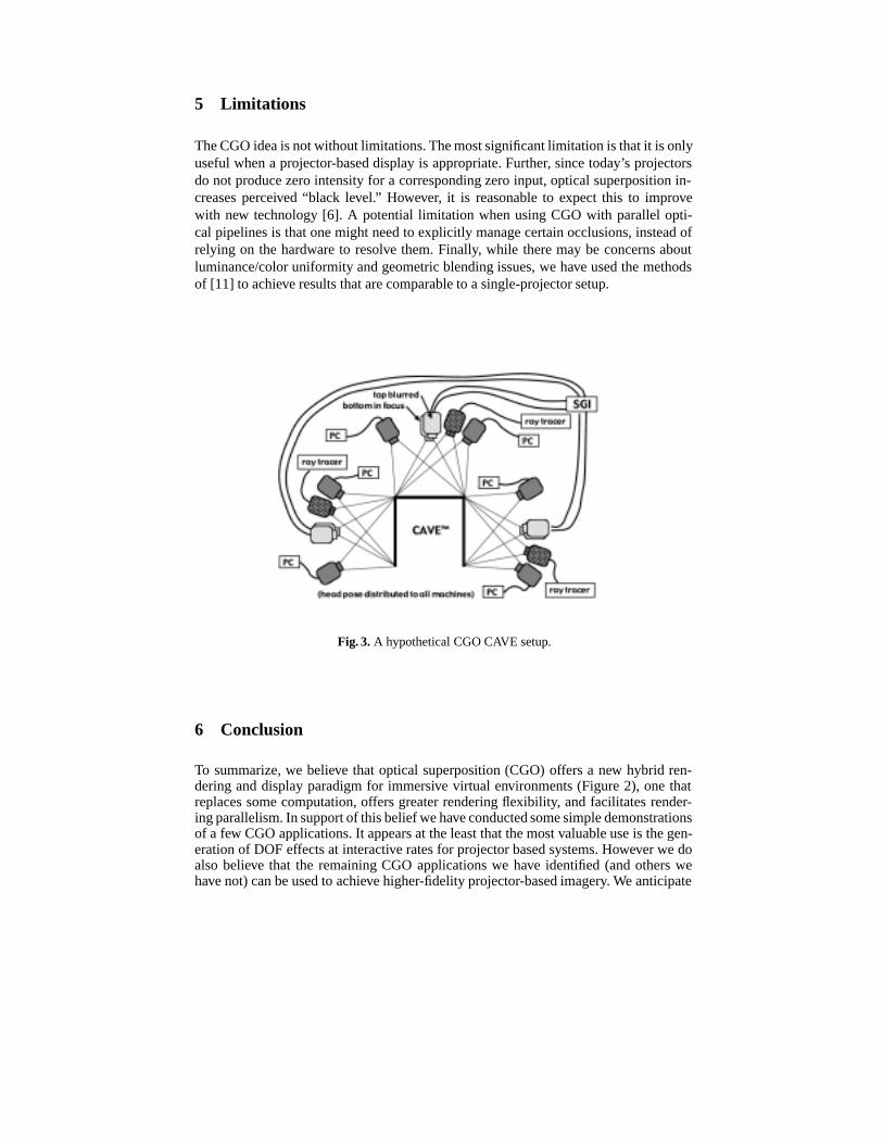
Fig. 3. A hypothetical CGO CAVE setup.
6 Conclusion
To summarize, we believe that optical superposition (CGO) offers a new hybrid ren-dering and display paradigm for immersive virtual environments (Figure 2), one thatreplaces some computation, offers greater rendering flexibility, and facilitates render-ing parallelism. In support of this belief we have conducted some simple demonstrationsof a few CGO applications. It appears at the least that the most valuable use is the gen-eration of DOF effects at interactive rates for projector based systems. However we doalso believe that the remaining CGO applications we have identified (and others wehave not) can be used to achieve higher-fidelity projector-based imagery. We anticipate
finding and/or developing a mathematical framework appropriate for the additive su-perposition of light, so that we can more rigorously find and characterize the uses andusefulness of CGO.
References
1. “Mercury: Realtime anti-aliasing 3d graphics sub-system,” Technical Report,http://www.quantum3D.com/products%20pages/mercury.html, [cited Jan 2000].
2. Rui Bastos.Superposition Rendering : Increased Realism for Interactive Walkthroughs. PhDthesis, University of North Carolina at Chapel Hill, Department of Computer Science, 1999.
3. R.A. Chorley and J. Laylock, “Human factor consideration for the interface between electro-optical display and the human visual system,” InDisplays, volume 4, 1981.
4. Carolina Cruz-Neira, Daniel J. Sandin, and Thomas A.Defanti, “Surround-screen projection-based virtual reality : The design and implementation of the cave,” InProceedings of ACMSiggraph, 1993.
5. “Flash : Graphics System and Architecture,”Department of Computer Science, Stanford Uni-versity, [cited on Jan 2001] Available from http://graphics.stanford.edu/projects/flashg/,
6. White Pages of ColorVision, http://www.colorvision-lasers.com/, [cited Jan 2001].7. P. Diefenbach and N. Badler, “Pipeline rendering : Interactive refractions, reflections and
shadows,” InDisplays(Special Issue on Interactive Computer Graphics), 1994.8. J.D. Foley, A. Van Dam, S.K. Feiner, and J.F.Hughes,Computer Graphics Principles and
Practice. Addison Wesley, 1990.9. Paul E. Haeberli and Kurt Akeley, “The accumulation buffer: Hardware support for high-
quality rendering,”Computer Graphics (Proceedings of SIGGRAPH 90), 24(4):309–318, Au-gust 1990.
10. G. Humphreys and P. Hanrahan, “A distributed graphics system for large tiled displays,” InProceedings of IEEE Visualization, 1999.
11. Aditi Majumder, Zue He, Herman Towles, and Greg Welch. “Achieving Color UniformityAcross Multi-Projector Displays,” InProceedings of Visualization, 2000.
12. Thomas L. Martzall, “Simultaneous raster and calligraphic crt projection system for flightsimulation,” InSPIE Proceedings,Electroluminescent Materials, Devices, and Large-ScreenDisplays, volume 1910, 01/31/1993 - 02/05/1993.
13. R. Raskar, G. Welch, M. Cutts, A. Lake, L. Stesin, and H. Fuchs, “The office of the future: Aunified approach to image based modeling and spatially immersive display,” InProceedingsof ACM Siggraph, pages 168–176, 1998.
14. Ramesh Raskar, “Immersive planar displays using roughly aligned projectors.” InProceed-ings of IEEE Virtual Reality 2000, 1999.
15. Samanta Rudro, Jiannan Zheng, Thomas Funkhouse, Kai Li, and Jaswinder Pal Singh, “Loadbalancing for multi-projector rendering systems,” InSIGGRAPH/Eurographics Workshop onGraphics Hardware, August 1999.
16. S.Molnar, J. Eyles, and J. Poulton, “Pixelflow : High-speed rendering using image composi-tion,” In Proceedings of SIGGPARH, pages 231–240, 1992.
17. M. Lacroix, “A HDTV Projector for Wide Field of View Flight Simulators,” Presented atIMAGE VI Conference, Scottsdale, AZ, July 14–17, 1992.
18. K. Talmi, J. Liu, “Eye and Gaze Tracking for Visually Controlled Interactive StereoscopicDisplays,” Proceedings ofImage Communication, 1998.
19. R.A. Chorley and J. Laylock, “Human factor consideration for the interface between electro-optical display and the human visual system,” InDisplays, volume 4, 1981.