Computer Graphics - Bryn Mawr€¦ · · 2010-10-04Computer Graphics Viewing ... Modeling...
57
Computer Graphics Viewing Transformations and Projection Based on slides by Dianna Xu, Bryn Mawr College
Transcript of Computer Graphics - Bryn Mawr€¦ · · 2010-10-04Computer Graphics Viewing ... Modeling...
Computer Graphics Viewing Transformations and Projection
Based on slides by Dianna Xu, Bryn Mawr College
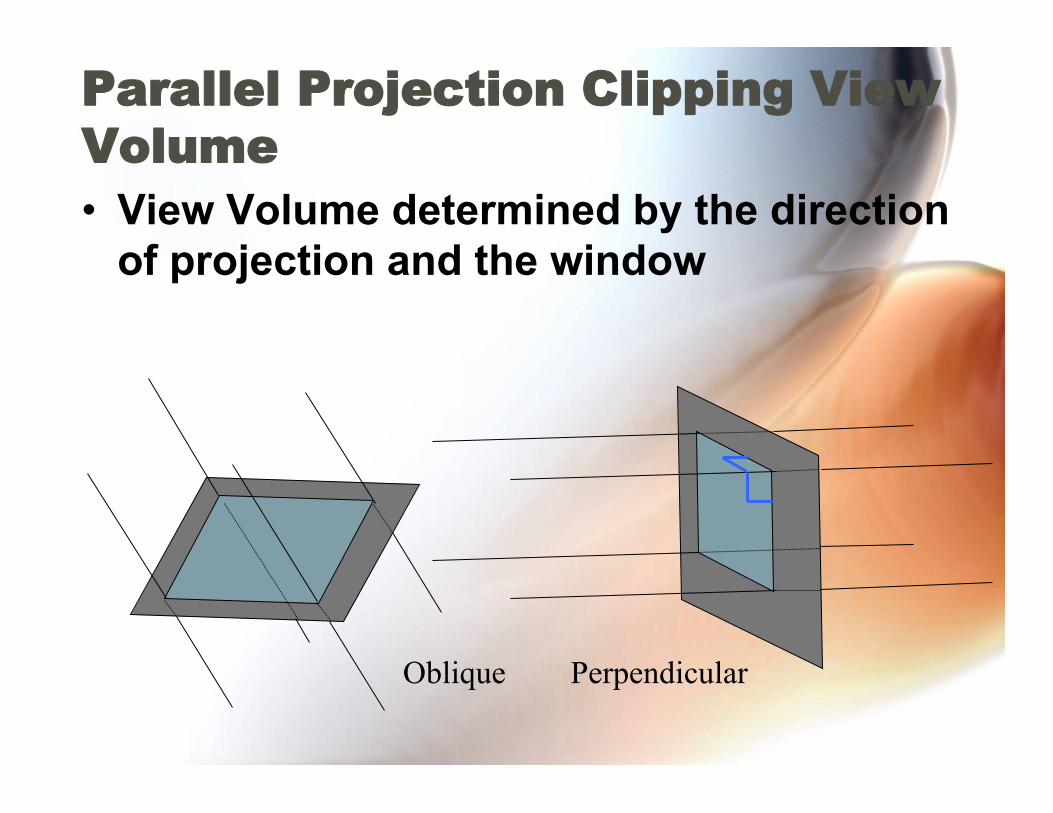
Parallel Projection Clipping View Volume • View Volume determined by the direction
of projection and the window
Oblique Perpendicular
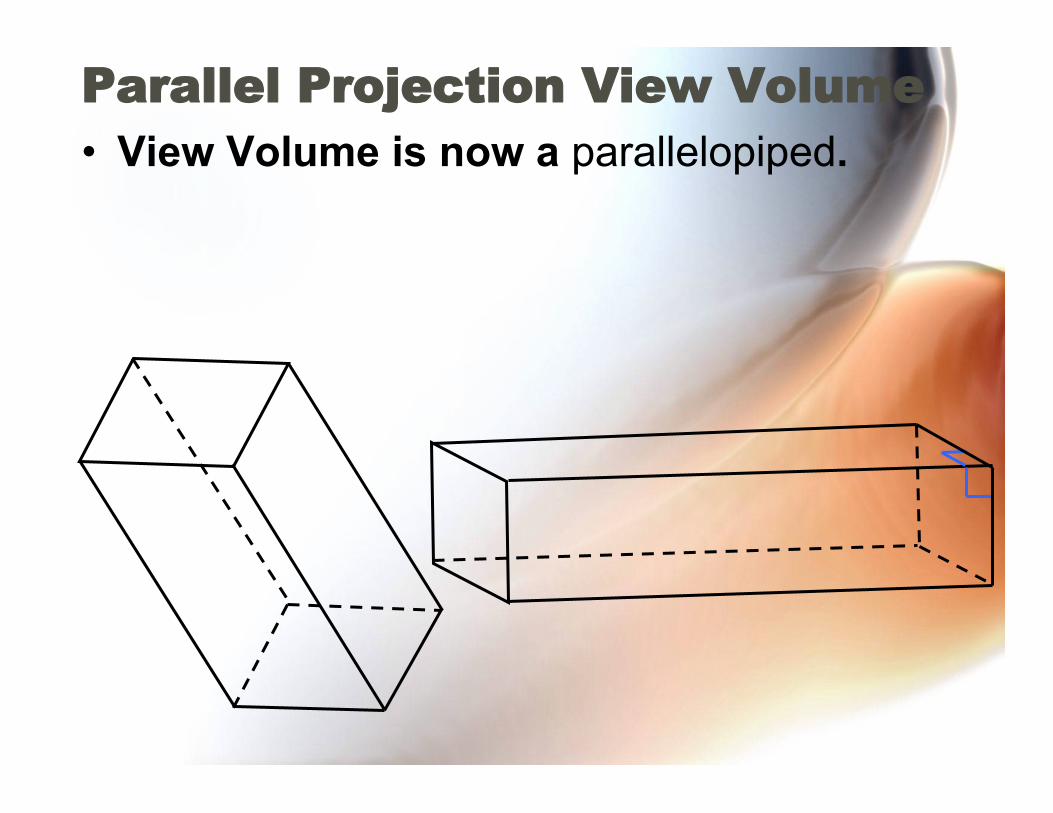
Parallel Projection View Volume • View Volume is now a parallelopiped.

The Synthetic Camera
• Translated via CP changes. • Rotated via UP changes. • Redirected via View Plane Normal changes
(e.g. panning). • Zoom via changes in View Distance
CP
NORM
V UP
View Distance
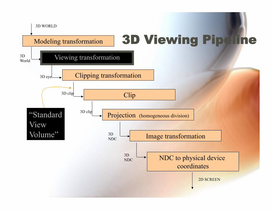
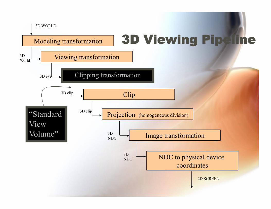
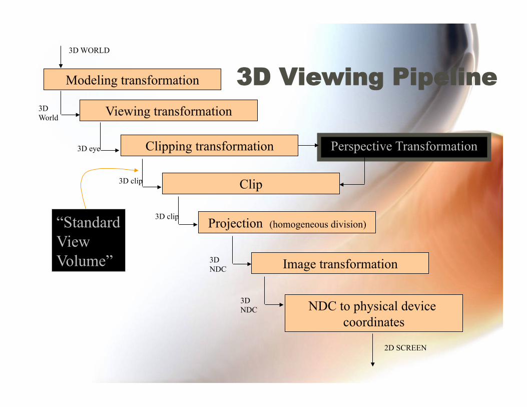
3D Viewing Pipeline Modeling transformation
Clipping transformation
Clip
Projection (homogeneous division)
Image transformation
NDC to physical device coordinates
3D WORLD
3D World
3D eye
3D clip
3D clip
3D NDC
3D NDC
2D SCREEN
“Standard View Volume”
Viewing transformation
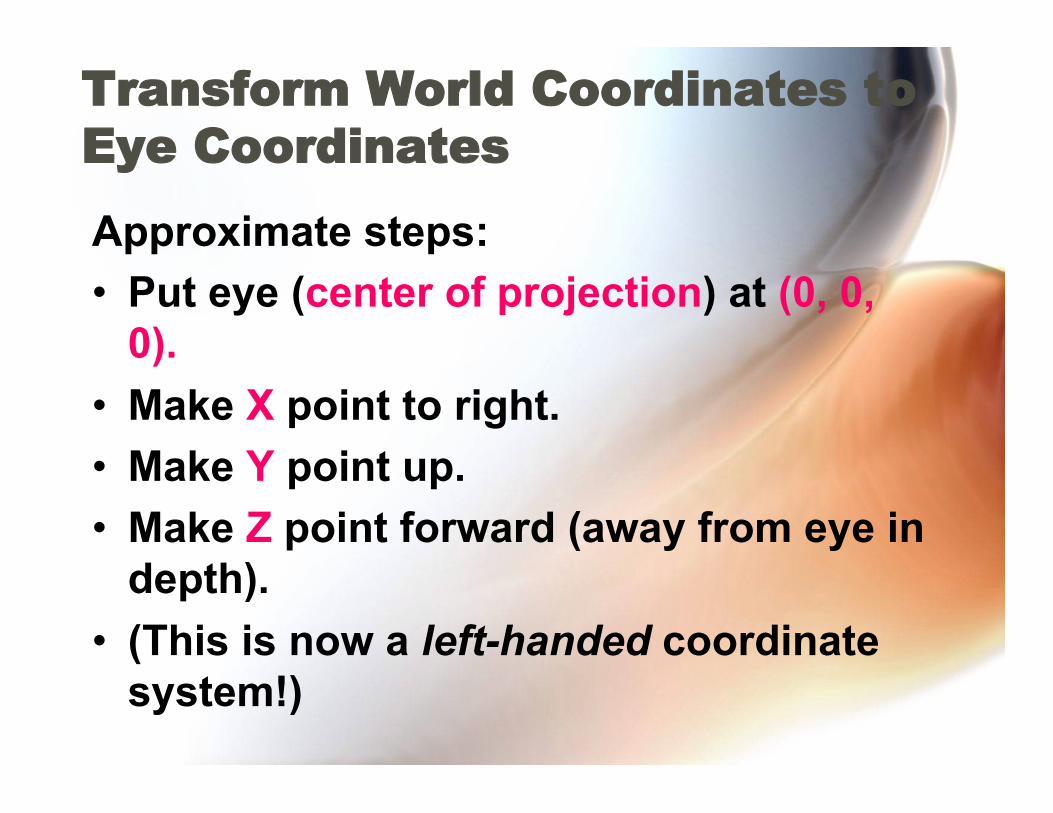
Transform World Coordinates to Eye Coordinates
Approximate steps: • Put eye (center of projection) at (0, 0,
0). • Make X point to right. • Make Y point up. • Make Z point forward (away from eye in
depth). • (This is now a left-handed coordinate
system!)

World to Eye Transformation START
X Y
Z
View direction
Eye = center of projection

World to Eye Transformation Translate eye to (0, 0, 0)
X Y
Z
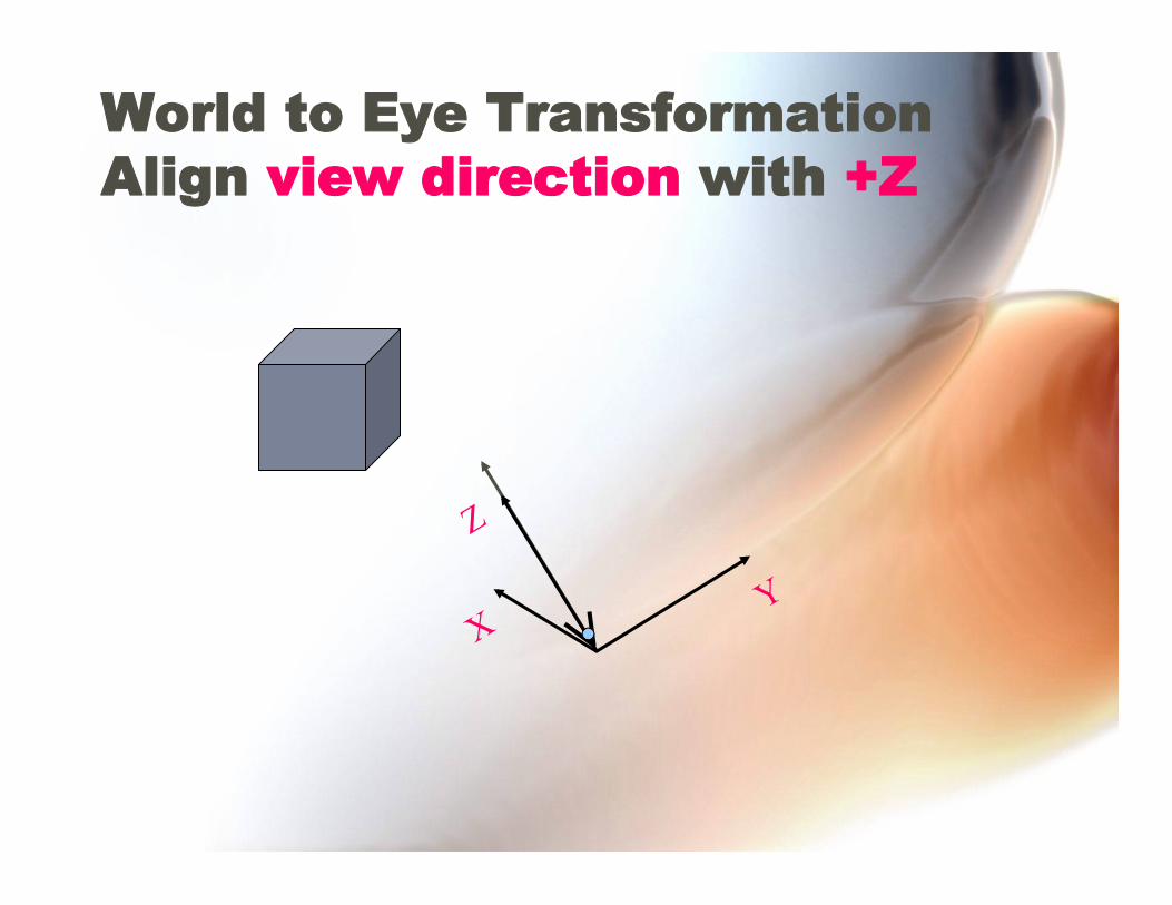
World to Eye Transformation Align view direction with +Z

World to Eye Transformation Align VUP direction with +Y
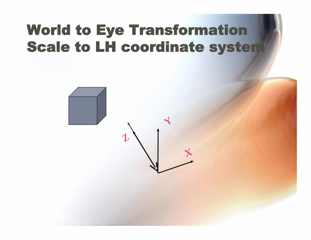
World to Eye Transformation Scale to LH coordinate system
3D Viewing Pipeline Modeling transformation
Viewing transformation
Clipping transformation
Clip
Projection (homogeneous division)
Image transformation
NDC to physical device coordinates
3D WORLD
3D World
3D eye
3D clip
3D clip
3D NDC
3D NDC
2D SCREEN
“Standard View Volume”
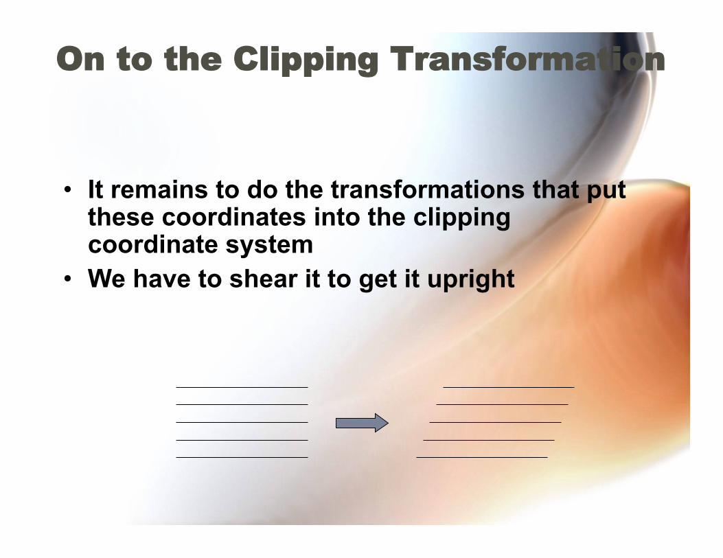
On to the Clipping Transformation
• It remains to do the transformations that put these coordinates into the clipping coordinate system
• We have to shear it to get it upright
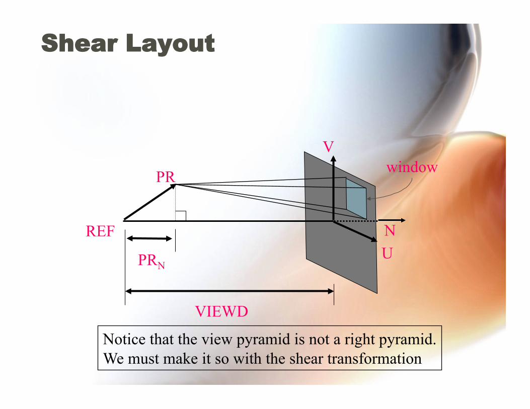
Shear Layout
REF N
V
VIEWD
U
PR
PRN
window
Notice that the view pyramid is not a right pyramid. We must make it so with the shear transformation

Scaling to Standard View Volume
window
ZC=FRONT-PRN
ZC
ZC=VIEWD-PRN
ZC=BACK-PRN
YC
XC
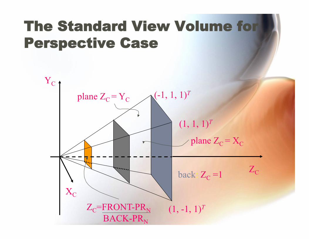
The Standard View Volume for Perspective Case
back: ZC =1
(1, -1, 1)T
(1, 1, 1)T
(-1, 1, 1)T YC
XC
ZC
ZC=FRONT-PRN BACK-PRN
plane ZC = YC
plane ZC = XC
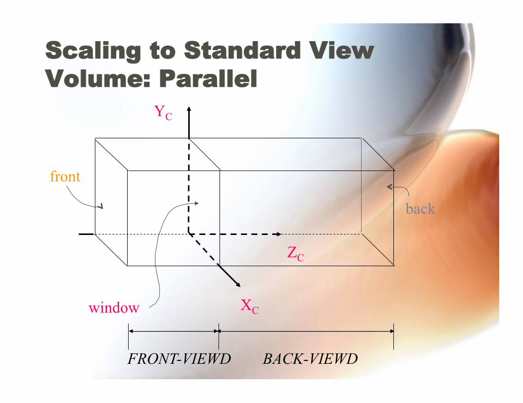
Scaling to Standard View Volume: Parallel
front
back
YC
XC
ZC
window
FRONT-VIEWD BACK-VIEWD
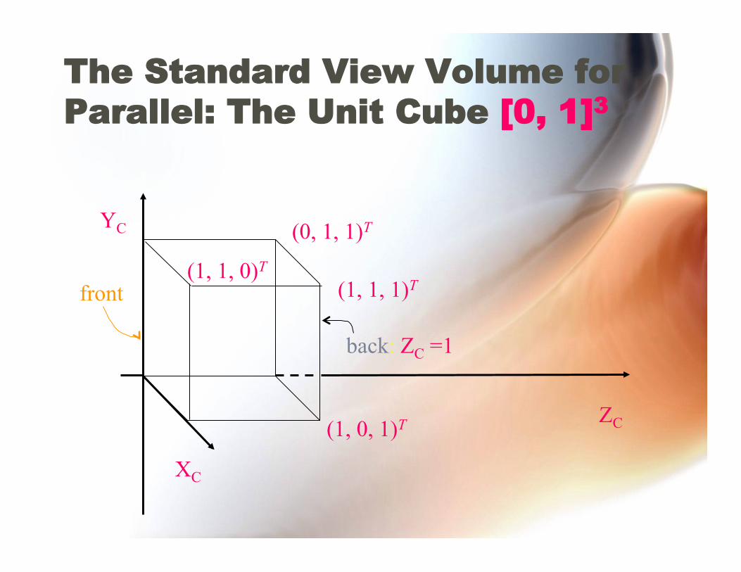
The Standard View Volume for Parallel: The Unit Cube [0, 1]3
front
back: ZC =1
YC
(1, 0, 1)T
(1, 1, 1)T
(0, 1, 1)T
(1, 1, 0)T
XC
ZC
3D Viewing Pipeline Modeling transformation
Viewing transformation
Clipping transformation
Clip
Projection (homogeneous division)
Image transformation
NDC to physical device coordinates
3D WORLD
3D World
3D eye
3D clip
3D clip
3D NDC
3D NDC
2D SCREEN
“Standard View Volume”
Perspective Transformation
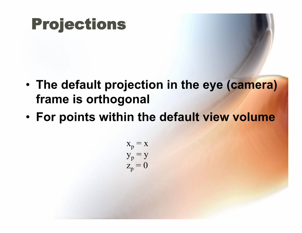
Projections
• The default projection in the eye (camera) frame is orthogonal
• For points within the default view volume
xp = x yp = y zp = 0
Normalization
• Most graphics systems use view normalization – All other views are converted to the default
view by transformations that determine the projection matrix
– Allows use of the same pipeline for all views
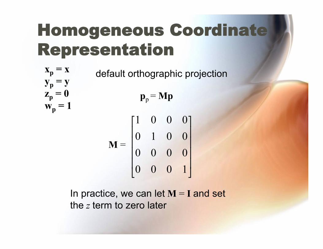
Homogeneous Coordinate Representation
xp = x yp = y zp = 0 wp = 1
pp = Mp
M =
In practice, we can let M = I and set the z term to zero later
default orthographic projection
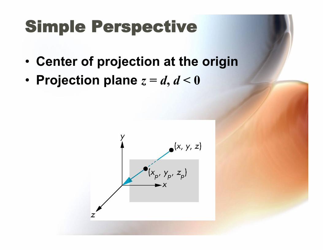
Simple Perspective
• Center of projection at the origin • Projection plane z = d, d < 0

Perspective Equations
Consider top and side views
xp = yp = zp = d
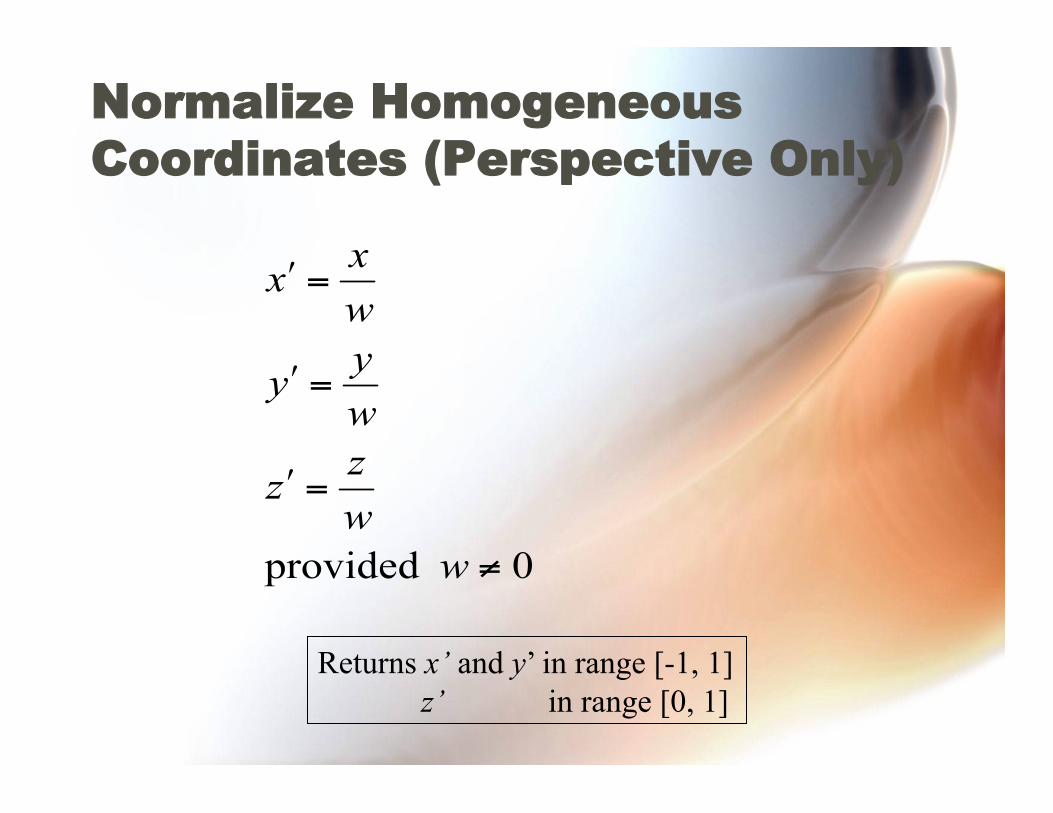
Normalize Homogeneous Coordinates (Perspective Only)
Returns x’ and y’ in range [-1, 1] z’ in range [0, 1]
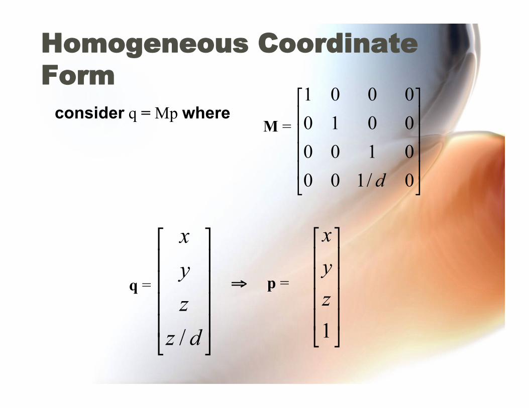
Homogeneous Coordinate Form
M = consider q = Mp where
q = ⇒ p =
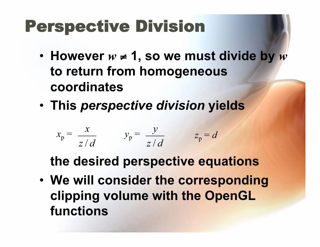
• However w ≠ 1, so we must divide by w to return from homogeneous coordinates
• This perspective division yields
the desired perspective equations • We will consider the corresponding
clipping volume with the OpenGL functions
Perspective Division
xp = yp = zp = d
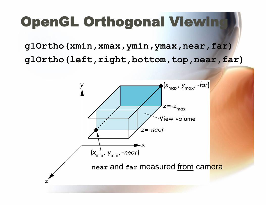
OpenGL Orthogonal Viewing
glOrtho(xmin,xmax,ymin,ymax,near,far) glOrtho(left,right,bottom,top,near,far)
near and far measured from camera
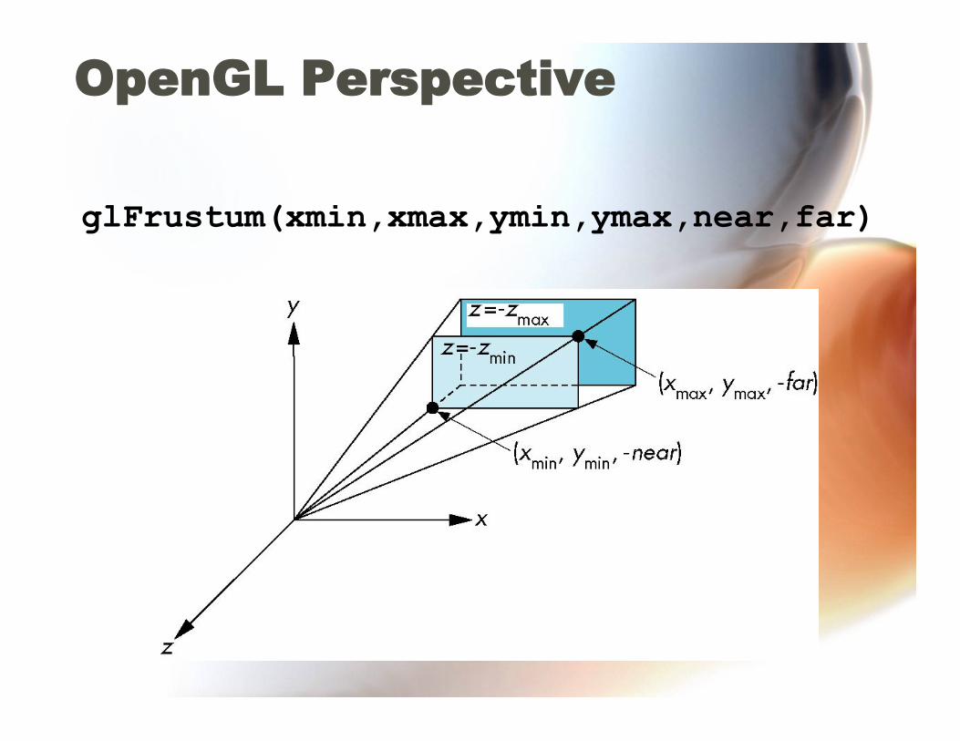
OpenGL Perspective
glFrustum(xmin,xmax,ymin,ymax,near,far)
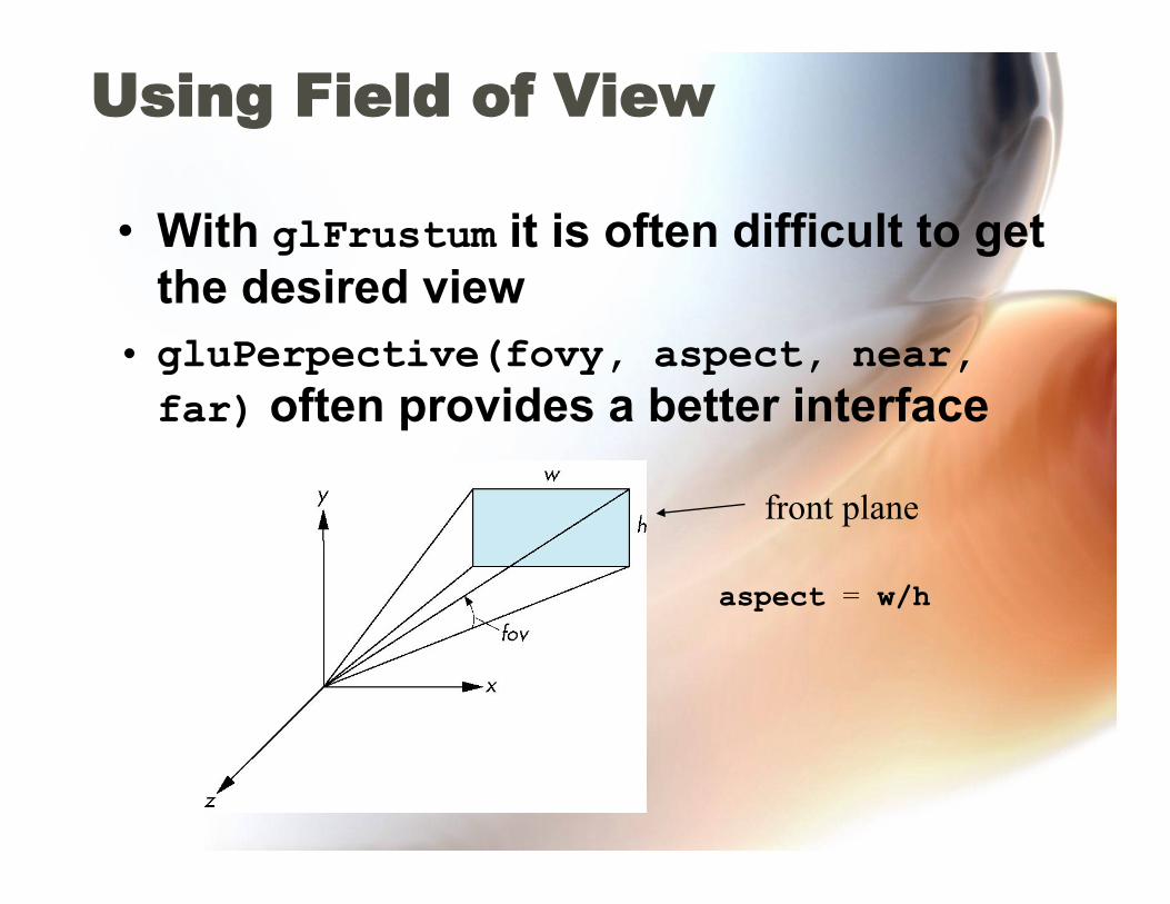
Using Field of View
• With glFrustum it is often difficult to get the desired view
• gluPerpective(fovy, aspect, near, far) often provides a better interface
aspect = w/h
front plane

Normalization
• Rather than derive a different projection matrix for each type of projection, we can convert all projections to orthogonal projections with the default view volume
• This strategy allows us to use standard transformations in the pipeline and makes for efficient clipping
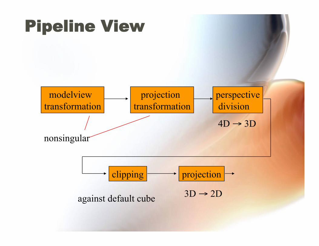
Pipeline View
modelview transformation
projection transformation
perspective division
clipping projection
nonsingular 4D → 3D
against default cube 3D → 2D
Notes
• We stay in 4D homogeneous coordinates through both the modelview and projection transformations – Both these transformations are nonsingular – Default to identity matrices (orthogonal
view) • Normalization lets us clip against simple
cube regardless of type of projection • Delay final projection until end
– Important for hidden-surface removal to retain depth information as long as possible
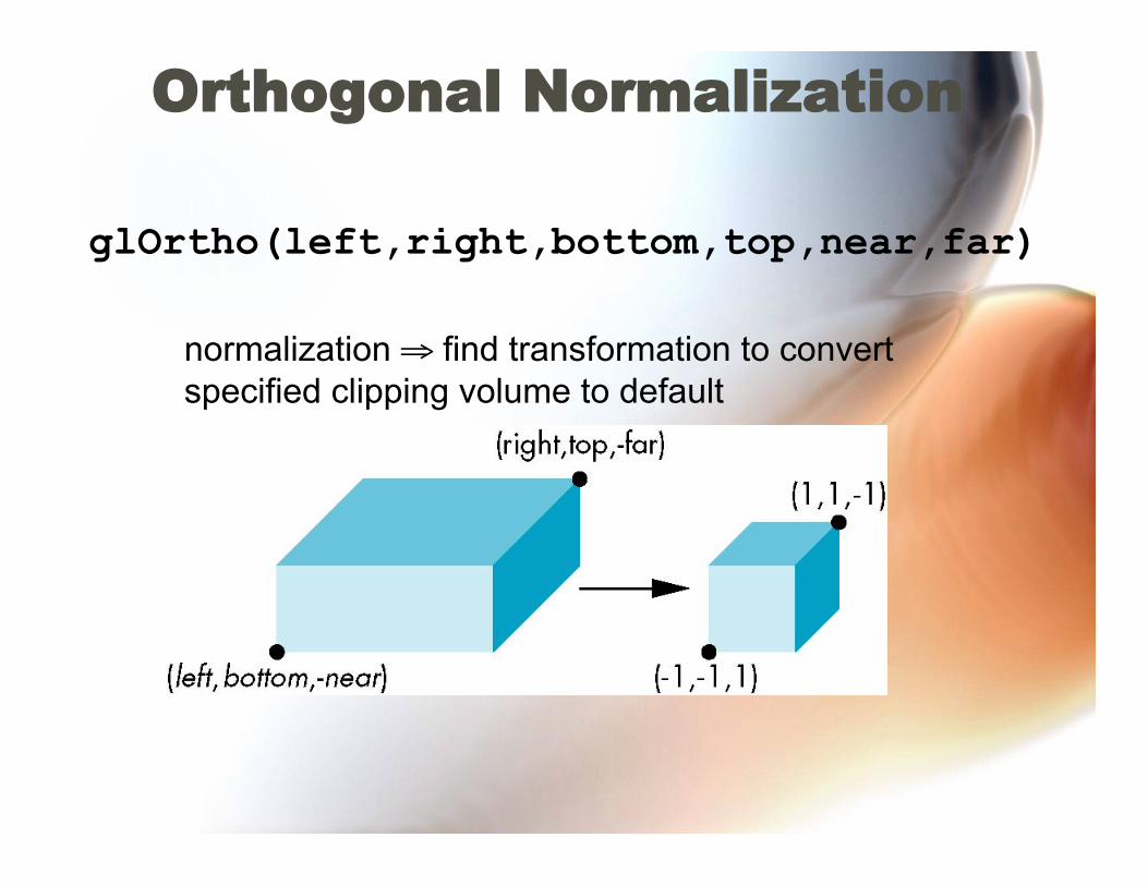
Orthogonal Normalization
glOrtho(left,right,bottom,top,near,far)
normalization ⇒ find transformation to convert specified clipping volume to default
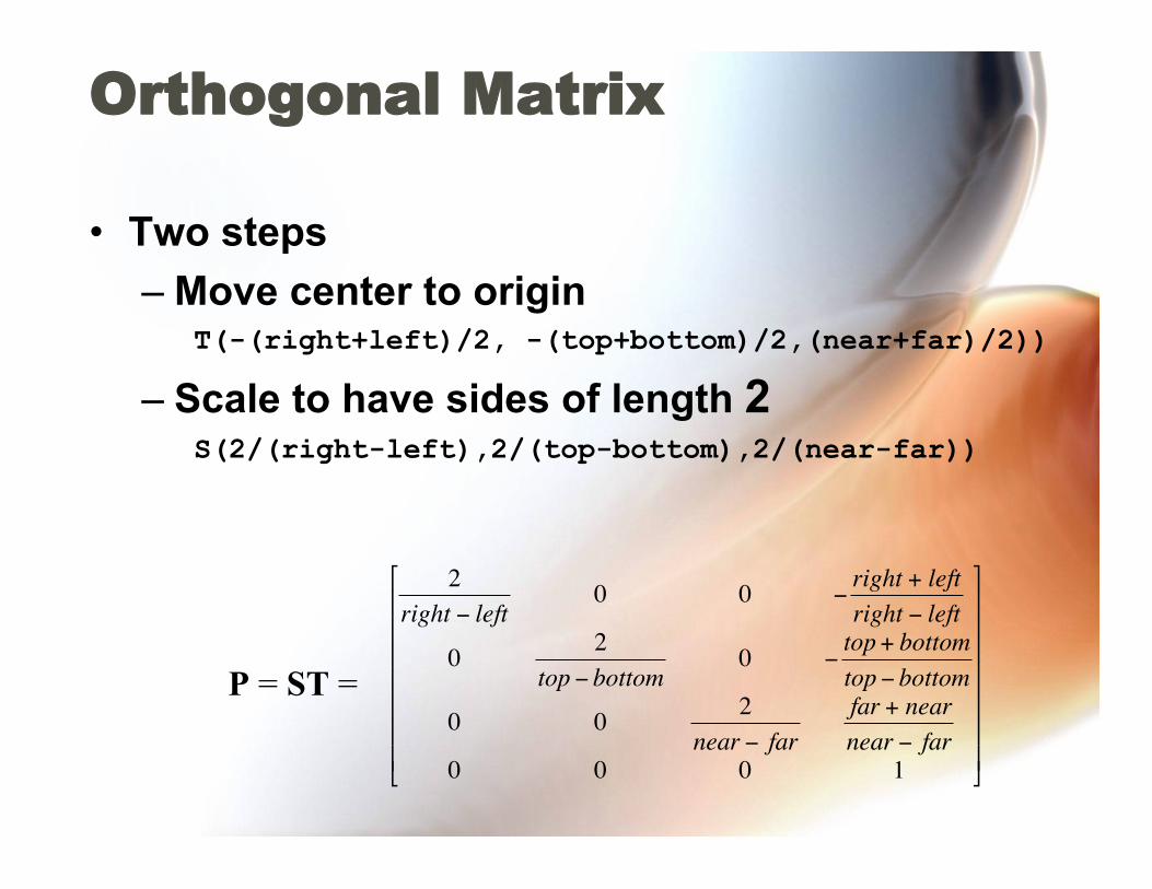
Orthogonal Matrix
• Two steps – Move center to origin
T(-(right+left)/2, -(top+bottom)/2,(near+far)/2))
– Scale to have sides of length 2 S(2/(right-left),2/(top-bottom),2/(near-far))
€
2right − left
0 0 −right + leftright − left
0 2top − bottom
0 −top+ bottomtop− bottom
0 0 2near − far
far + nearnear − far
0 0 0 1
⎡
⎣
⎢ ⎢ ⎢ ⎢ ⎢ ⎢ ⎢
⎤
⎦
⎥ ⎥ ⎥ ⎥ ⎥ ⎥ ⎥
P = ST =
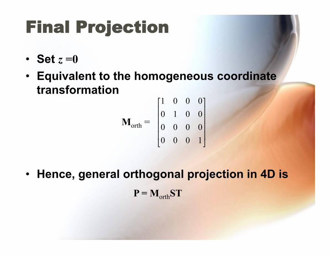
Final Projection
• Set z =0 • Equivalent to the homogeneous coordinate
transformation
• Hence, general orthogonal projection in 4D is
Morth =
P = MorthST
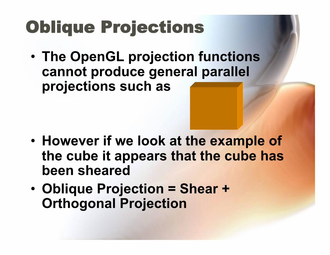
Oblique Projections
• The OpenGL projection functions cannot produce general parallel projections such as
• However if we look at the example of the cube it appears that the cube has been sheared
• Oblique Projection = Shear + Orthogonal Projection

General Shear
top view side view

Shear Matrix xy shear (z values unchanged)
Projection matrix
General case:
H(θ,φ) =
P = Morth H(θ,φ)
P = Morth STH(θ,φ)
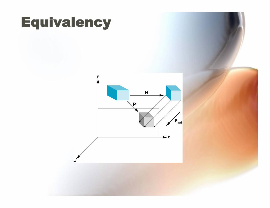
Equivalency

Effect on Clipping
• The projection matrix P = STH transforms the original clipping volume to the default clipping volume
top view
DOP DOP
near plane
far plane
object
clipping volume
z = -1
z = 1
x = -1 x = 1
distorted object (projects correctly)
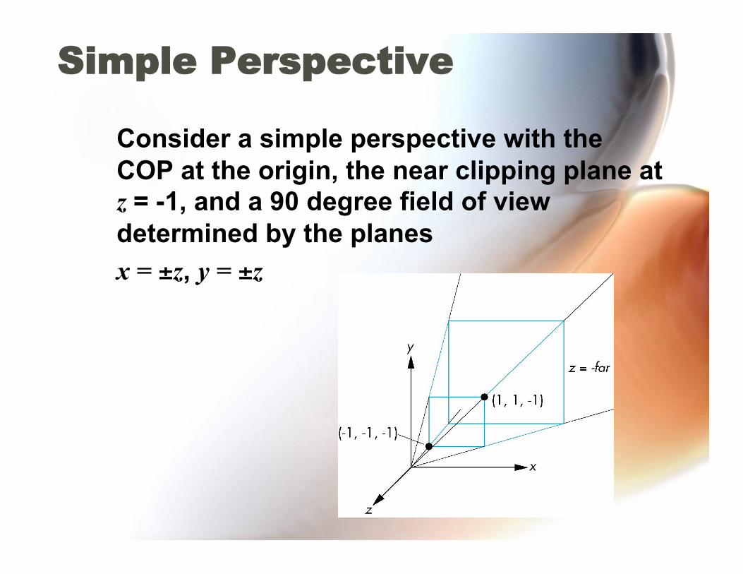
Simple Perspective
Consider a simple perspective with the COP at the origin, the near clipping plane at z = -1, and a 90 degree field of view determined by the planes
x = ±z, y = ±z
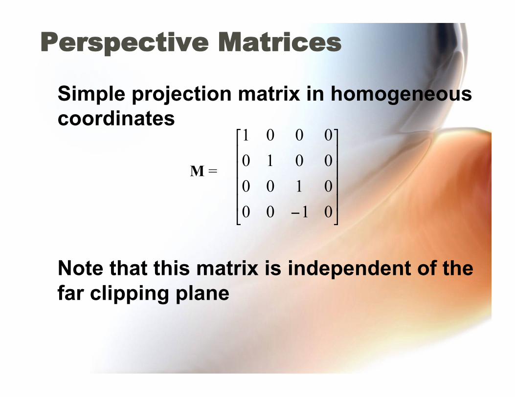
Perspective Matrices
Simple projection matrix in homogeneous coordinates
Note that this matrix is independent of the far clipping plane
M =
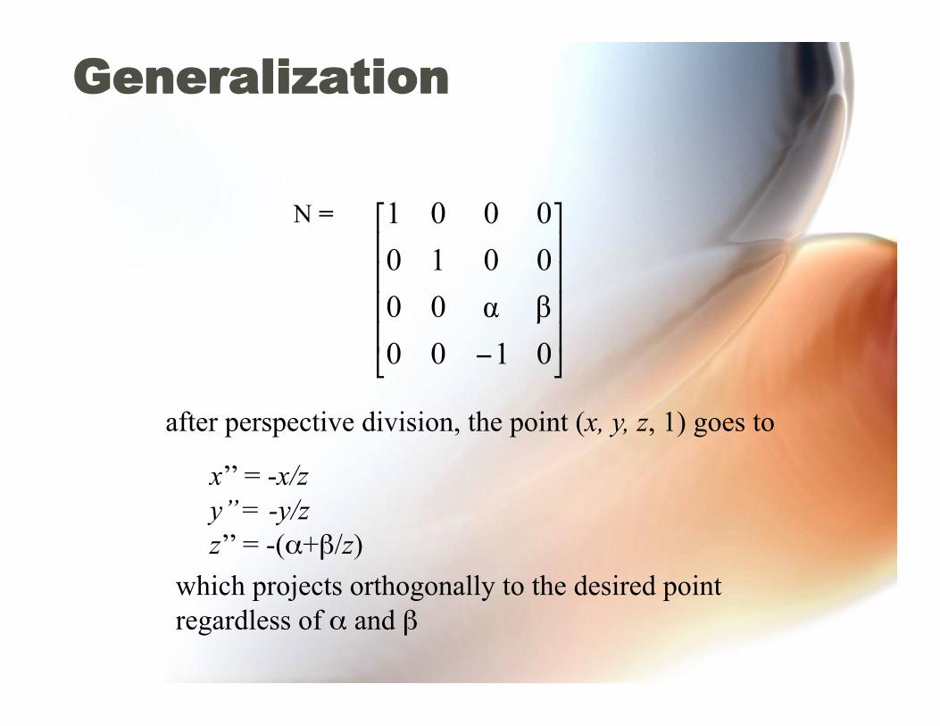
Generalization
N =
after perspective division, the point (x, y, z, 1) goes to
x’’ = -x/z y’’ = -y/z z’’ = -(α+β/z)
which projects orthogonally to the desired point regardless of α and β
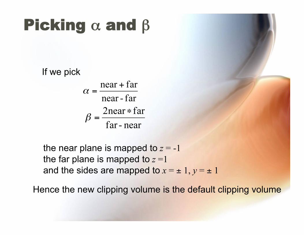
Picking α and β
If we pick
the near plane is mapped to z = -1 the far plane is mapped to z =1 and the sides are mapped to x = ± 1, y = ± 1
Hence the new clipping volume is the default clipping volume

Normalization Transformation
original clipping
volume original object new clipping
volume
distorted object projects correctly
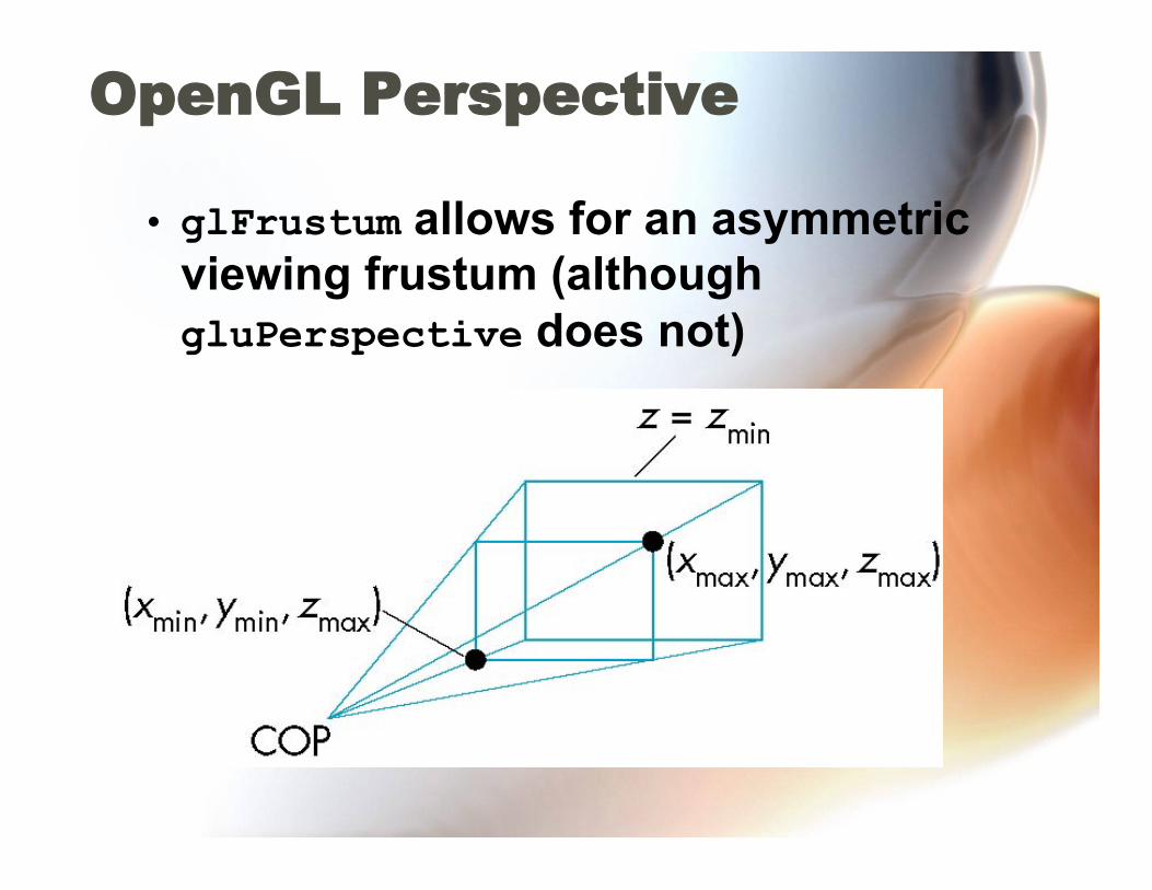
OpenGL Perspective
• glFrustum allows for an asymmetric viewing frustum (although gluPerspective does not)
OpenGL Perspective Matrix
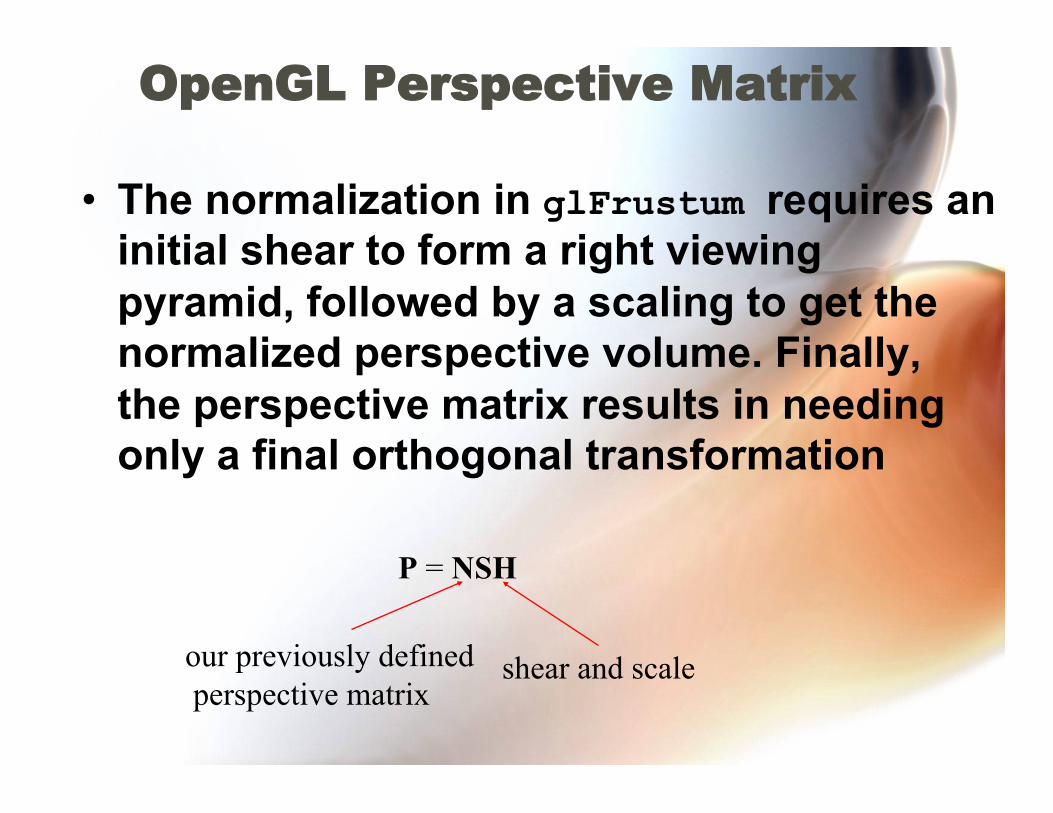
• The normalization in glFrustum requires an initial shear to form a right viewing pyramid, followed by a scaling to get the normalized perspective volume. Finally, the perspective matrix results in needing only a final orthogonal transformation
P = NSH
our previously defined perspective matrix
shear and scale

OpenGL Perspective Matrix • H (shear): skew the point ((left+right)/2, (top
+bottom)/2, -near) to (0, 0, -near) • S (scale): scale the sides to x = ±z, y = ±z • N (normalization): get the far plan to z = -1
and the near plane to z = 1
€
P = NSH =
−2* nearright − left
0 right + leftright − left
0
0 −2* neartop − bottom
top+ bottomtop− bottom
0
0 0 far + nearnear − far
2 far* nearfar − near
0 0 −1 0
⎡
⎣
⎢ ⎢ ⎢ ⎢ ⎢ ⎢ ⎢
⎤
⎦
⎥ ⎥ ⎥ ⎥ ⎥ ⎥ ⎥

Why do we do it this way?
• Normalization allows for a single pipeline for both perspective and orthogonal viewing
• We keep in four dimensional homogeneous coordinates as long as possible to retain three-dimensional information needed for hidden-surface removal and shading
• We simplify clipping
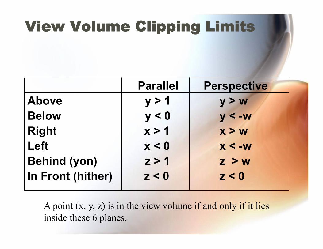
View Volume Clipping Limits
Parallel Perspective Above y > 1 y > w Below y < 0 y < -w Right x > 1 x > w Left x < 0 x < -w Behind (yon) z > 1 z > w In Front (hither) z < 0 z < 0
A point (x, y, z) is in the view volume if and only if it lies inside these 6 planes.
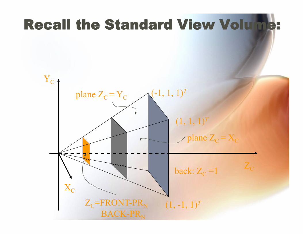
Recall the Standard View Volume:
back: ZC =1
(1, -1, 1)T
(1, 1, 1)T
(-1, 1, 1)T YC
XC
ZC
ZC=FRONT-PRN BACK-PRN
plane ZC = YC
plane ZC = XC
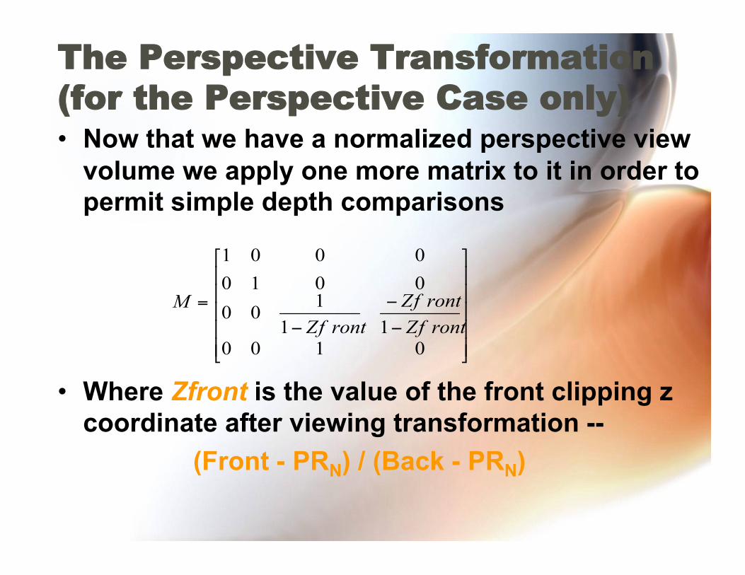
The Perspective Transformation (for the Perspective Case only) • Now that we have a normalized perspective view
volume we apply one more matrix to it in order to permit simple depth comparisons
• Where Zfront is the value of the front clipping z coordinate after viewing transformation -- (Front - PRN) / (Back - PRN)
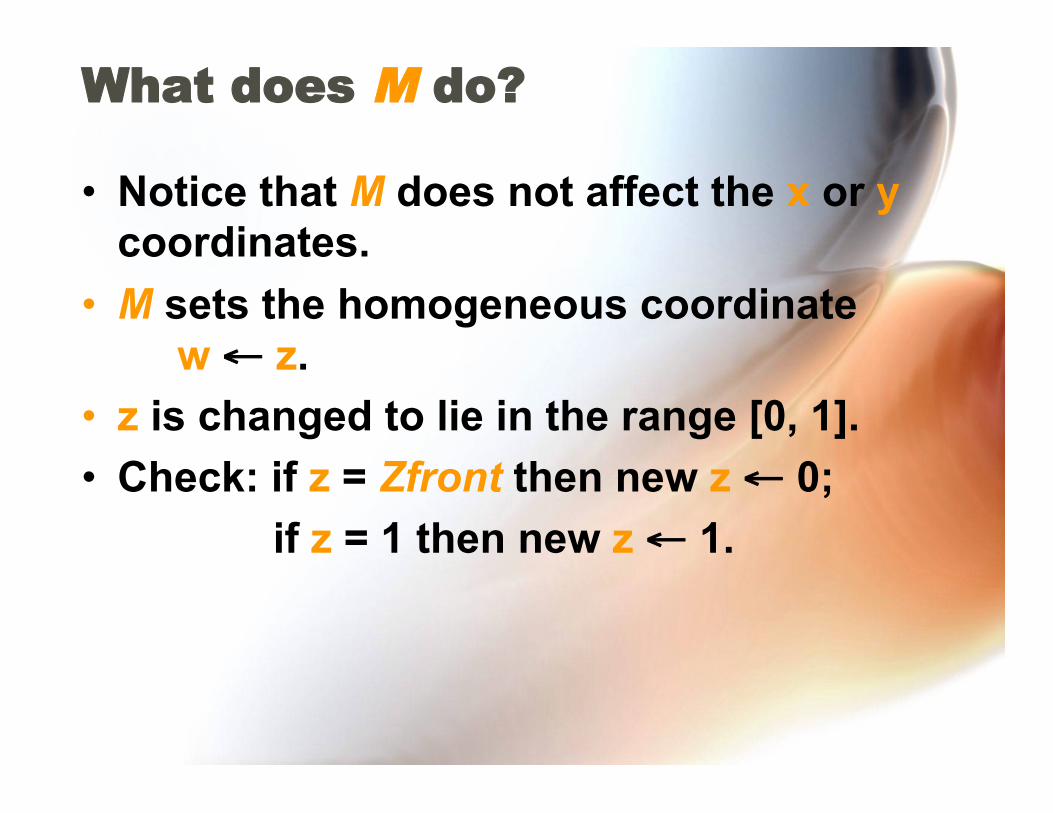
What does M do?
• Notice that M does not affect the x or y coordinates.
• M sets the homogeneous coordinate w ← z.
• z is changed to lie in the range [0, 1]. • Check: if z = Zfront then new z ← 0;
if z = 1 then new z ← 1.
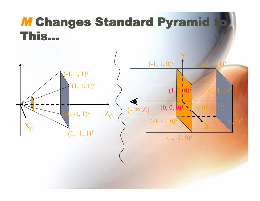
M Changes Standard Pyramid to This...
(1, -1, 1)T
(1, 1, 1)T
(-1, 1, 1)T
XC
ZC
Y
X
(- ∞ Z)
(-1, 1, 1)T
(1, -1, 1)T
(1, 1, 1)T
(-1, -1, 1)T
(1, -1, 0)T
(-1, 1, 0)T
(-1, -1, 0)T
(1, 1, 0)T
(-1, -1, 1)T (0, 0, 0)T (0, 0, 1)T
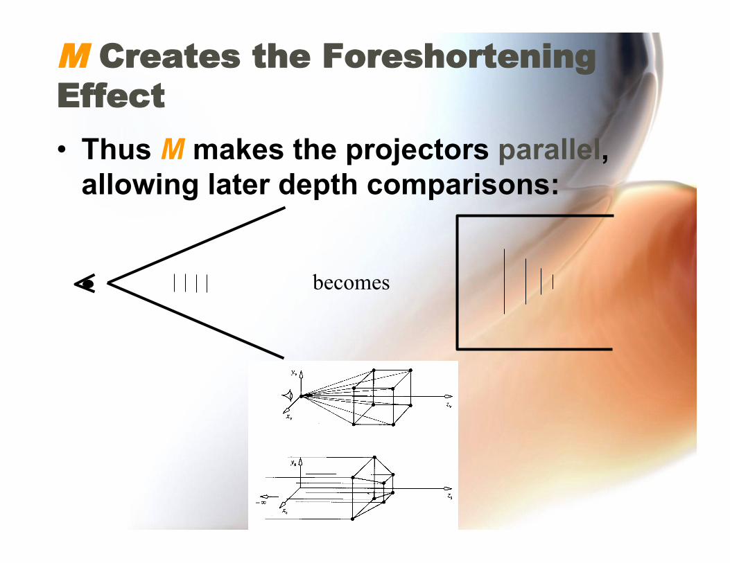
M Creates the Foreshortening Effect
• Thus M makes the projectors parallel, allowing later depth comparisons:
becomes
The Perspective Transformation M
• Preserves relative depth. • Preserves linearity (“straightness”). • Preserves planarity. • Produces perspective foreshortening. • Still permits clipping -- just use W
coordinate.