Computer based drawing management system
17
United States Patent [19] Alker et al. I [11] Patent Number: [45] Date of Patent: 4,665,555 May 12, 1987 [54] COMPUTER BASED DRAWING MANAGEMENT SYSTEM [75] Inventors: Bruce B. Alker; Michael J. ’ McGovern, both of Thousand Oaks, Calif. [73] Assignee: Alpharel Incorporated, Camarillo, Calif. [21] Appl. No.: 710,079 [22] Filed: Mar. 11, 1985 [51] Int. Cl.4 ........................ .. 609G 1/06; G06K 9/00 [52] U.S. Cl. .................................... .. 382/41; 340/ 724; 340/731; 340/747; 382/57 [58] Field of Search ..................... .. 340/724, 731, 747; 382/41, 44, 56, 57; 353/25, 26 R, 26 A, 27 R, 27 A; 364/518, 521 [56] References Cited U.S. PATENT DOCUMENTS 4,121,196 10/1978 Johnson et al. ..................... .. 382/41 4,197,590 4/1980 Sukonick et a1. 340/731 4,388,610 6/1983 Tsunekawa . . . . . . . . . .. 382/56 4,532,605 7/1985 Waller ............................... .. 340/731 Primary Examiner—Leo H. Boudreau Attorney, Agent, or Firm-Freilich, Hornbaker, Rosen & Fernandez [57] ABSTRACT A system for use with large libraries of existing techni cal drawings for permitting the drawings to be electron ically captured and digitally stored in a central data base. As needed, the documents can be retrieved, dis played, electronically revised, and printed out. The system includes scanners which scan existing drawings to generate a bit stream of pixel data which is then compressed and stored in a mass storage unit. A draw ing revisory subsystem is provided capable of operating in a DRAWING REVISION MODE and a DRAW ING REDISPLAY MODE. When operating in the DRAWING REVISION MODE, as the operator in puts revisory commands, the revisory subsystem gener ates primitives which modify the displayed drawing in real time by changing a bit map stored in a dedicated pixel memory driving a display monitor. Additionally, however, the revisory subsystem automatically caches the primitives de?ning the desired drawing revisions. At the completion of a revisory session, the cached primitives are grouped as a designated REVISION LEVEL and stored in the mass storage unit. When operating in the DRAWING REDISPLAY MODE, the compressed pixel data is expanded and stored in the pixel memory to cause the monitor to display the origi nal drawing. The redisplayed drawing is then revised through its successive REVISION LEVELS in an incremental or cinematic manner by successively revis ing the bit map in the pixel memory. 12 Claims, 11 Drawing Figures l6 / 26 »’’\O 30 2o / COMMUNlOATlON ’ APERTURE SUBsYSFEM GRAPl-HC. CA RD DISPLAY SCANNER TERM‘NAL [32 FULL size 12 24 SCANNER l 22 8 f f1 o I I , DATA DRAWING -l COMPRESSION —- £1055 - REWEORY RECCZ‘QDER ! I54 —* MODULE suesvs'rw A size 42 SCANNER DRAWING RECORDER 1 l \4 g 44 f M A55 OTHER 5T0 RAeE RECORDER
Transcript of Computer based drawing management system
United States Patent [19] Alker et al. I
[11] Patent Number:
[45] Date of Patent: 4,665,555
May 12, 1987
[54] COMPUTER BASED DRAWING MANAGEMENT SYSTEM
[75] Inventors: Bruce B. Alker; Michael J. ’ McGovern, both of Thousand Oaks, Calif.
[73] Assignee: Alpharel Incorporated, Camarillo, Calif.
[21] Appl. No.: 710,079
[22] Filed: Mar. 11, 1985
[51] Int. Cl.4 ........................ .. 609G 1/06; G06K 9/00 [52] U.S. Cl. .................................... .. 382/41; 340/ 724;
340/731; 340/747; 382/57 [58] Field of Search ..................... .. 340/724, 731, 747;
382/41, 44, 56, 57; 353/25, 26 R, 26 A, 27 R, 27 A; 364/518, 521
[56] References Cited U.S. PATENT DOCUMENTS
4,121,196 10/1978 Johnson et al. ..................... .. 382/41
4,197,590 4/1980 Sukonick et a1. 340/731 4,388,610 6/1983 Tsunekawa . . . . . . . . . .. 382/56
4,532,605 7/1985 Waller ............................... .. 340/731
Primary Examiner—Leo H. Boudreau Attorney, Agent, or Firm-Freilich, Hornbaker, Rosen & Fernandez
[57] ABSTRACT
A system for use with large libraries of existing techni
cal drawings for permitting the drawings to be electron ically captured and digitally stored in a central data base. As needed, the documents can be retrieved, dis played, electronically revised, and printed out. The system includes scanners which scan existing drawings to generate a bit stream of pixel data which is then compressed and stored in a mass storage unit. A draw ing revisory subsystem is provided capable of operating in a DRAWING REVISION MODE and a DRAW ING REDISPLAY MODE. When operating in the DRAWING REVISION MODE, as the operator in puts revisory commands, the revisory subsystem gener ates primitives which modify the displayed drawing in real time by changing a bit map stored in a dedicated pixel memory driving a display monitor. Additionally, however, the revisory subsystem automatically caches the primitives de?ning the desired drawing revisions. At the completion of a revisory session, the cached primitives are grouped as a designated REVISION LEVEL and stored in the mass storage unit. When operating in the DRAWING REDISPLAY MODE, the compressed pixel data is expanded and stored in the pixel memory to cause the monitor to display the origi nal drawing. The redisplayed drawing is then revised through its successive REVISION LEVELS in an incremental or cinematic manner by successively revis ing the bit map in the pixel memory.
12 Claims, 11 Drawing Figures
l6 / 26 »’’\O 30 2o
/ COMMUNlOATlON ’ APERTURE SUBsYSFEM GRAPl-HC. CA RD DISPLAY
SCANNER TERM‘NAL
[32 FULL size 12 24 SCANNER l 22 8 f f1 o
I I , DATA DRAWING
-l COMPRESSION —- £1055 - REWEORY RECCZ‘QDER ! I54 —* MODULE suesvs'rw
A size 42 SCANNER
DRAWING RECORDER
1
l \4 g 44
f
M A55 OTHER 5T0 RAeE RECORDER

US. Patent Mayl2,1987 Sheet4of5 ' 4,665,555 \\
S - \OO BUS / 2
\ V \44\
1 \50 I52 \40 . V / 32 V K I / /
GFG "WRWE’ Ps Pc/Ps"REAo" DATA "\1 To "WR\TE_” ADDR F1 F0
DECODE DECODE DECODE (pmM mvE CACHE AND UMP
\‘54 D PR\M\T\\/1=_ I LOAD STORAGE)
OR ‘56/; DATA om
lNTERRUPT FlFo FULL. _ cnzcun" ‘
\24)l I13. 4
MAIN sue OTHER MENU MENU MENU >
DRAW ‘ PEN W \ DTH
ERAsE Ln\\\=_ ' > O
I MOVE Box 2
TRANSFORM . RECTANGLE 5 \ 4
I i 324 . l
I ' 522 : ‘520 i x | l
Iij- 7
(A) (B) <c> <D)_ (a)
U. S. Patent May 12, 1987
: CACHE. l I pRuvnTu/isl
L____.__
15:9. 6"‘
Sheet 5 of 5 4,665,555 200
BEem
{2oz RETRHQ/E DIRK-ANAL. 50o DRAVWNG
,204 IN )TIATE *302 P IXEL RETR\ EVE EDW omemALw W06 DRAW\N6 MPLJ CREATEQ. + r304 PRMWWE REQUEsT
L\sT RE\/\S\ON LEVEL
_____ _] £05 + ,306
PR\M\Tl\/E5 TO RETRHLVE. eFeTo MODiFy REVEAON LEVEL
EMT MAP PmMmvEs, 6TORE \N FWO
_“___' + ,302 y 2 \2
MPU ROUTES Ravmou vmmmvas sesworq TO 6%
COMPLETE? 5 l0 2\4 + ’
r C? F6 ‘
\N\T\A'TE Mommas STORE EH’ MAP
FUNCT‘ON
' + 286 - r 0 6
MPU DUMPS . —9 FH=O TO
MAE‘: sToRAeE
+ (212, APPEND LIN KlNG \NFO
4,665,555 1
COMPUTER BASED DRAWING MANAGEMENT SYSTEM
FIELD OF THE INVENTION
This invention relates generally to computer based systems useful for electronically storing, revising, and displaying technical drawings and other documents. More speci?cally, this invention relates to improve ments in such systems for greatly enhancing their ability to efficiently revise electronically stored drawings.
BACKGROUND OF THE INVENTION
Systems are disclosed in the prior art for electroni cally storing and retrieving documents. Such prior art systems variously utilize analog and digital storage techniques and are exempli?ed by US. Pat. Nos. 4,205,780 and 4,388,610. Additional patents variously show relevant subsystems for (1) scanning documents; (2) storing electronic document data; (3) modifying stored electronic data; and (4) displaying or producing hard copy output of stored data. For example, see:
IMAGE-DATA HANDLING
. Pat. No. 4,394,774
. Pat. No. 4,369,463
. Pat. No. 4,307,377
. Pat. No. 4,189,711
. Pat. No. 3,876,831
STORAGE AND RETRIEVAL
. Pat. No. 4,271,430
. Pat. No. 4,152,722
. Pat. No. 4,141,078
. Pat. No. 4,020,463
. Pat. No. 3,868,637
. Pat. No. 3,854,004
. Pat. No. 3,757,037
. Pat. No. 3,751,582
. Pat. No. 3,697,680
PRINTING, SCANNING, EDITING & STORING
. Pat. No. 4,333,153
. Pat. No. 4,270,173
. Pat. No. 4,270,172
. Pat. No. 4,231,096
. Pat. No. 4,196,450
. Pat. No. 4,038,493
. Pat. No. 3,828,319
. Pat. No. 3,653,071
. Pat. No. 3,601,590
SUMMARY OF THE INVENTION
The present invention is particularly directed to an improved system for digitizing existing technical draw ings and for storing the digital data so generated so that the data can later be retrieved for display, electronic revision, and hard copy output of the drawings.
Systems in accordance with the invention are in tended primarily for use with large libraries of existing technical drawings to permit the drawings to be elec tronically captured and digitally stored in a central data base. As needed, the documents can then be retrieved, displayed, electronically revised, and printed out, if required. Systems in accordance with the invention are intended to accept a wide variety of existing drawing formats, e.g. from aperture cards to full size originals as well as a wide range of drawing sizes, e.g. from A size
10
20
25
30
35
40
45
60
65
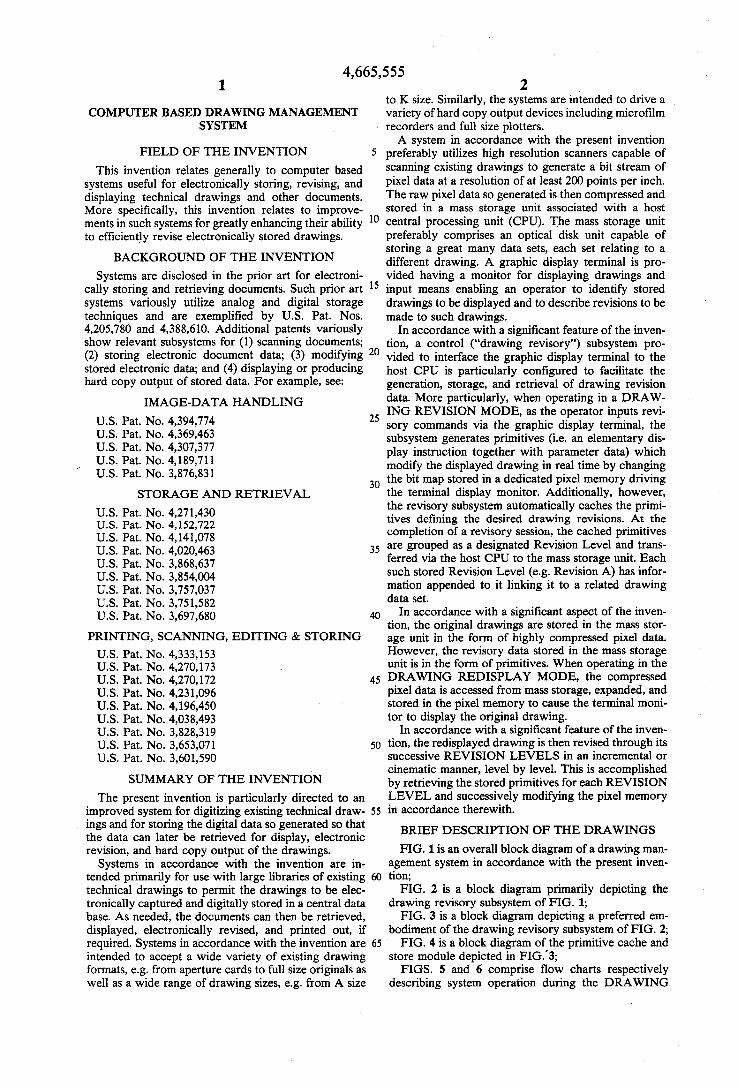
2 to K size. Similarly, the systems are intended to drive a variety of hard copy output devices including micro?lm recorders and full size plotters. A system in accordance with the present invention
preferably utilizes high resolution scanners capable of scanning existing drawings to generate a bit stream of pixel data at a resolution of at least 200 points per inch. The raw pixel data so generated is then compressed and stored in a mass storage unit associated with a host central processing unit (CPU). The mass storage unit preferably comprises an optical disk unit capable of storing a great many data sets, each set relating to a different drawing. A graphic display terminal is pro vided having a monitor for displaying drawings and input means enabling an operator to identify stored drawings to be displayed and to describe revisions to be made to such drawings.
In accordance with a signi?cant feature of the inven tion, a control (“drawing revisory”) subsystem pro vided to interface the graphic display terminal to the host CPU is particularly con?gured to facilitate the generation, storage, and retrieval of drawing revision data. More particularly, when operating in a DRAW ING REVISION MODE, as the operator inputs revi sory commands via the graphic display terminal, the subsystem generates primitives (i.e. an elementary dis play instruction together with parameter data) which modify the displayed drawing in real time by changing the bit map stored in a dedicated pixel memory driving the terminal display monitor. Additionally, however, the revisory subsystem automatically caches the primi tives de?ning the desired drawing revisions. At the completion of a revisory session, the cached primitives are grouped as a designated Revision Level and trans ferred via the host CPU to the mass storage unit. Each such stored Revision Level (e.g. Revision A) has infor mation appended to it linking it to a related drawing data set.
In accordance with a signi?cant aspect of the inven tion, the original drawings are stored in the mass stor age unit in the form of highly compressed pixel data. However, the revisory data stored in the mass storage unit is in the form of primitives. When operating in the DRAWING REDISPLAY MODE, the compressed pixel data is accessed from mass storage, expanded, and stored in the pixel memory to cause the terminal moni tor to display the original drawing.
In accordance with a signi?cant feature of the inven tion, the redisplayed drawing is then revised through its successive REVISION LEVELS in an incremental or cinematic manner, level by level. This is accomplished by retrieving the stored primitives for each REVISION LEVEL and successively modifying the pixel memory in accordance therewith.
BRIEF DESCRIPTION OF THE DRAWINGS
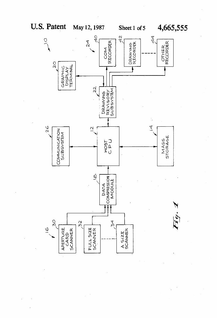
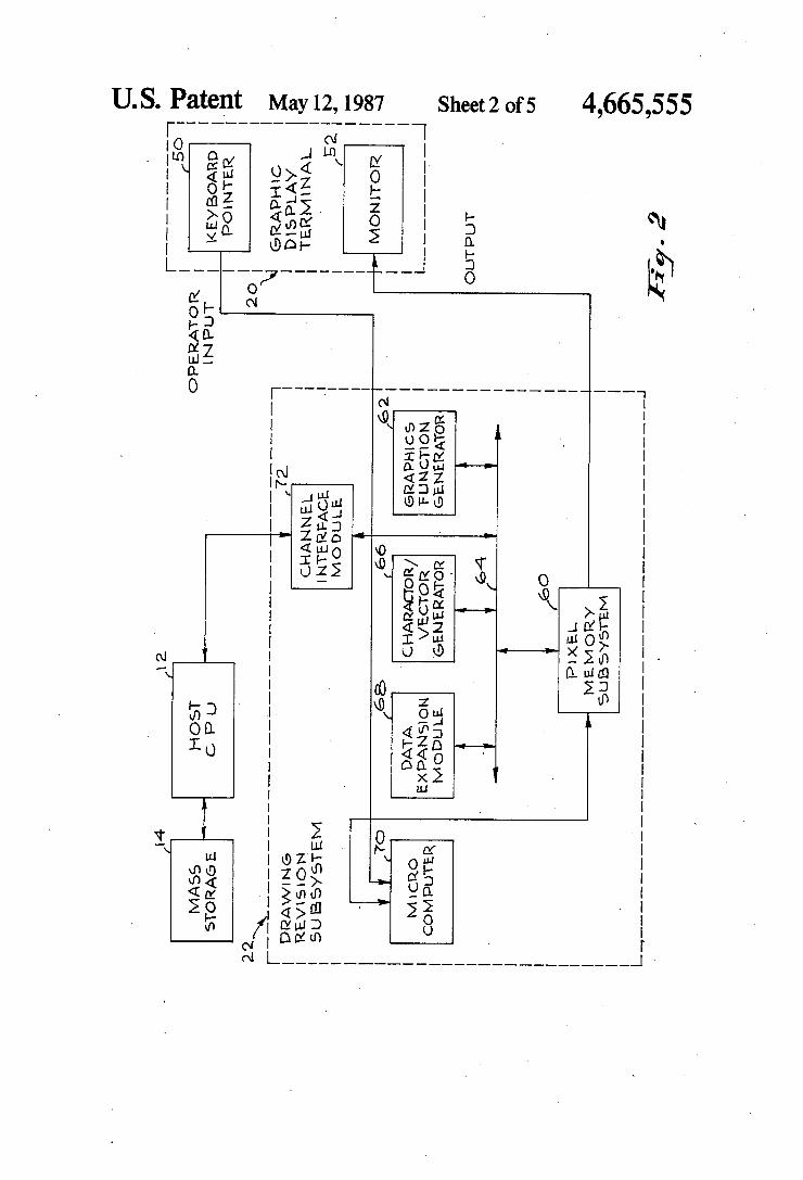
FIG. 1 is an overall block diagram of a drawing man agement system in accordance with the present inven tion; FIG. 2 is a block diagram primarily depicting the
drawing revisory subsystem of FIG. 1; FIG. 3 is a block diagram depicting a preferred em
bodiment of the drawing revisory subsystem of FIG. 2; FIG. 4 is a block diagram of the primitive cache and
store module depicted in FIG.'3; FIGS. 5 and 6 comprise ?ow charts respectively
describing system operation during the DRAWING
4,665,555 3
REVISION MODE and the incremental DRAWING REDISPLAY MODE in accordance with the present
invention; FIG. 7 depicts exemplary display menus; FIG. 8 depicts the execution of an exemplary com
mand; and FIGS. 9A, 9B, 9C contain Table 3 which depicts byte
formats of exemplary display primitives.
DESCRIPTION OF PREFERRED EMBODIMENT
Attention is now directed to FIG. 1 which comprises a block diagram of a drawing management system 10 in accordance with the present invention. The system includes a host central processing unit (CPU) 12 having a large mass storage unit 14 coupled thereto. The system 10 is intended to operate with large li
braries of existing technical drawings to facilitate the electronic storage, revision, display, and hard copy output of the drawings. In order to initially electroni cally capture the information in an existing physical drawing, an appropriate one of scanning devices 16 scans the drawing to generate a binary data stream representing the pixel information in the drawing. A compression module 18 processes the binary data stream and converts it to a highly compressed forrn enabling it to be efficiently stored as a unique drawing data set in the mass storage unit 14. It should be under stood that each drawing is only scanned which it is initially presented to the system. This initial scanning results in the host CPU 12 storing a digital representa tion, i.e. a drawing data set of the drawing in mass stor age unit 14. In subsequent operations involving each drawing, whether for display, revision, or hard print out, the data set corresponding to that drawing is ac cessed from mass storage 14 and operated upon. System 10 further includes a graphic display terminal
20 which, as will be seen hereinafter, includes an opera tor input device and a display monitor. By proper utili zation of the terminal 20, an operator communicates commands to the host CPU 12 via a control subsystem which, hereinafter, will generally be referred to as the drawing revisory subsystem 22.
In addition to interfacing the graphic display terminal 20 to the host CPU 12, the drawing revisory subsystem 22 interfaces CPU 12 with various output devices in cluding display monitors and hard copy recorders 24. The system preferably also includes a communication subsystem 26 which enables system 10 to effectively operate with remote stations.
Prior to describing the preferred embodiment de picted in FIGS. 2-5, the intended application of system 10 will be brie?y discussed. The system 10 is primarily intended for applications involving very large libraries of ‘technical drawings (e.g. in excess of 100,000 draw= ings). Many large industrial companies, as well as gov= ernment agencies maintain libraries of working and archival drawings of this size. The management of such libraries involves the storage, retrieval, revision, and reproduction of the drawings. This management func tion is generally cumbersome and expensive. Typically, the drawings vary in size from A size through K size as depicted by the following table:
20
25
35
45
50
55
60
65
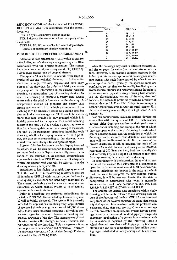
4 TABLE 1
DWG SIZE (in.)
A 85 X 11 B 11 X 17 C 17 X 22 D 22 X 34 E 34 X 44 F 28 X 40 G ll X 42-l44 H 28 X 48-144 1 34 X 48-l44 K 40 X 48-144
Also, the drawings may exist in different formats; i.e. full size on paper (or vellum) or reduced size on micro ?lm. However, it has become common practice in the industry at this time to capture most drawings on micro ?lm frames with each frame carried by what is known as an aperture card. Typically, the aperture cards are con?gured so that they can be readily handled by elec tromechanical storage and retrieval systems. In order to accommodate a typical existing drawing base contain ing the aforementioned variety of drawing sizes and formats, the system 10 preferrably includes a variety of scanner devices 16. Thus, FIG. 1 depicts an exemplary scanner group including an aperture card scanner 30, a full size drawing scanner 32, and a high speed A size scanner 34.
Various commercially available scanner devices are compatible with the system of FIG. 1. Such scanner devices differ from one another in their performance characteristics including, for example, the rate at which they can operate, the variety of drawing formats which can be accommodated, and the resolution at which the drawings can be scanned. The details of such scanner units will not be discussed herein. For purposes of the present disclosure, it will be assumed that each of the scanners 16 is able to scan a drawing at an effective resolution of 200 lines per inch, both horizontally (X) and vertically (Y), and output a bit stream of raw pixel data representing the content of the drawing.
In accordance with the invention, the raw bit stream output of the scanner 16 is subjected to a compression operation in data compression module 18. Various com pression techniques are known in the prior art which could be used to compress the raw scanner output. However, it will be assumed herein that the data is compressed in accordance with what is generally known as the Frank code described in U.S. Pat. Nos.
3,883,847; 4,103,287; 4,107,648; and 4,189,711. The compressed digital data associated with a single
drawing will herein be referred to as a drawing data set. One of the functions of the host CPU 12 is to store and keep track of the several hundred thousand data sets in a typical system. In accordance with the preferred em bodiment, these data sets are stored in a mass storage unit 14, preferably an optical disk system having a stor age capacity in the several hundred gigabyte range. An exemplary application of a system in accordance with the invention is depicted by the following Table 2 which demonstrates that a 421.8 gigabyte optical mass storage unit can store approximately four million draw ing pages distributed variously amongst A-K size draw ings.
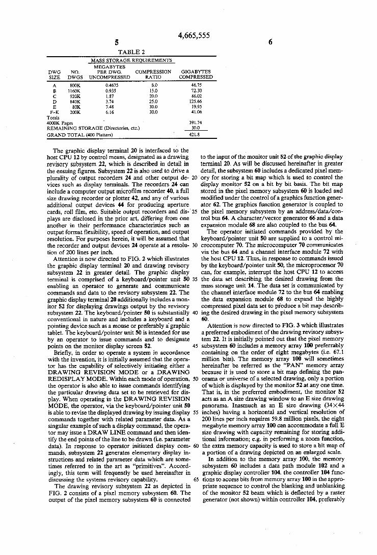
4,665,555 5 6 TABLE 2
MASS STORAGE REQUIREMENTS MEGABYTES
DWG NO. PER DWG. COMPRESSION GIGABYTES SIZE DWGS UNCOMPRESSED RATIO COMPRESSED
A BOOK 0.4675 8.0 46.75 B 1160K 0.935 15.0 72.30 C 920K 1.87 20.0 86.02 D 840K 3.74 25.0 125.66 E 80K 7.48 30.0 19.95
F-K 200K 6.16 30.0 41.06 Totals 4000K Pages 391.74 REMAINING STORAGE (Directories, etc.) 300 GRAND TOTAL (400 Platters) 421.8
The graphic display terminal 20 is interfaced to the host CPU 12 by control means, designated as a drawing revisory subsystem 22, which is described in detail in the ensuing ?gures. Subsystem 22 is also used to drive a
to the input of the. monitor unit 52 of the graphic display terminal 20. As will be discussed hereinafter in greater detail, the subsystem 60 includes a dedicated pixel mem
plurality of output recorders 24 and other output de- 20 ory for storing a bit map which is used to control the vices such as display terminals. The recorders 24 can display monitor 52 on a bit by bit basis. The bit map include a computer output micro?lm recorder 40, a full stored in the pixel memory subsystem 60 is loaded and size drawing recorder or plotter 42, and any of various modi?ed under the control of a graphics function gener additional output devices 44 for producing aperture ator 62. The graphics function generator is coupled to cards, roll film, etc. Suitable output recorders and dis-' 25 the pixel memory subsystem by an address/data/con plays are disclosed in the prior art, differing from one trol bus 64. A character/vector generator 66 and a data another in their performance characteristics such as expansion module 68 are also coupled to the bus 64. output format ?exibility, speed of operation, and output The operator initiated commands provided by the resolution. For purposes herein, it will be assumed that keyboard/pointer unit 50 are supplied to a control mi the recorder and output devices 24 operate at a resolu- 30 crocomputer 70. The microcomputer 70 communicates tion of 200 lines per inch. via the bus 64 and a channel interface module 72 with
Attention is now directed to FIG. 2 which illustrates the host CPU 12. Thus, in response to commands issued the graphic display terminal 20 and drawing revisory by the keyboard/pointer unit 50, the microprocessor 70 subsystem 22 in greater detail. The graphic display can, for example, interrupt the host CPU 12 to access terminal is comprised of a keyboard/pointer unit 50 35 the data set describing the desired drawing from the enabling an operator to generate and communicate mass storage unit 14. The data set is communicated by commands and data to the revisory subsystem 22. The the channel interface module 72 to the bus 64 enabling graphic display terminal 20 additionally includesamon- the data expansion module 68 to expand the highly itor 52 for displaying drawings output by the revisory compressed pixel data set to produce a bit map describ subsystem 22. The keyboard/pointer 50 is substantially 4O ing the desired drawing in the pixel memory subsystem conventional in nature and includes a keyboard and a pointing device such as a mouse or preferably a' graphic tablet. The keyboard/pointer unit 50 is intended for use by an operator to issue commands and to designate points on the monitor display screen 52.
Brie?y, in order to operate a system in accordance with the invention, it is initially assumed that the opera tor has the capability of selectively initiating either a DRAWING REVISION MODE or a DRAWING
45
60. Attention is now directed to FIG. 3 which illustrates
a preferred embodiment of the drawing revisory subsys tem 22. It is initially pointed out that the pixel memory subsystem 60 includes a memory array 100 preferrably containing on the order of eight megabytes (i.e. 67.1 million bits). The memory array 100 will sometimes hereinafter be referred as the “PAN” memory array because it is used to store a bit map de?ning the pan
REDISPLAY MODE. Within each mode of operation, 50 orama or universe of a selected drawing, only a portion the operator is also able to issue commands identifying of which is displayed by the monitor 52 at any one time. the particular drawing data set to be retrieved for dis- That is, in the preferred embodiment, the monitor 52 play. When operating in the DRAWING REVISION acts as an A size drawing window to an E size drawing MODE, the operator, via the keyboard/pointer unit 50 panorama. Inasmuch as an E size drawing (34><44 is able to revise the displayed drawing by issuing display 55 inches) having a horizontal and vertical resolution of commands together with related parameter data. As a 200 lines per inch requires 59.8 million pixels, the eight singular example of such a display command, the opera- megabyte memory array 100 can accommodate a full E tor may issue a DRAW LINE command and then iden- size drawing with capacity remaining for storing addi tify the end points of the line to be drawn (i.e. parameter tional information; e.g. in performing a zoom function, data). In response to operator initiated display com- 60 the extra memory capacity is used to store a bit map of mands, subsystem 22 generates elementary display in- a portion of a drawing depicted on an enlarged scale. structions and related parameter data which are some- In addition to the memory array 100, the memory times referred to in the art as “primitives”. Accord- subsystem 60 includes a data path module 102 and a ingly, this term will frequently be used hereinafter in graphic display controller 104. the controller 104 func discussing the systems revisory capability. 65 tions to access bits from memory array 100 in the appro The drawing revisory subsystem 22 as depicted in
FIG. 2 consists of a pixel memory subsystem 60. The output of the pixel memory subsystem 60 is connected
priate sequence to control the blanking and unblanking of the monitor 52 beam which is deflected by a raster generator (not shown) within controller 104, preferably
4,665,555 7
operating at 158 MHZ. Controller 104 preferably re freshes the monitor directly from the memory array 100 at an interlaced frame rate of 30 Hz. A preferred moni tor displays 2200 lines vertically (i.e. 200 lines per inch><1l inches) and 1728 lines horizontally (200x 8.64 inches). The graphics function generator 62 comprises a very
fast high speed data processor (e.g. bit slice micro processor) and associated microcode memory 106. The processor 106 is coupled to the aforementioned address /data/control bus 64. Similarly, the aforementioned character/vector generator 66, data expansion module 68, and channel interface module 72, are connected to the bus 64. The microcomputer 70 is depicted as being com
prised of a single board microcomputer including mi croprocessor 106, e. g. MOTOROLA 68000. Associated with the microprocessor 106 is a global memory 108 and input/output circuitry 110. The microprocessor 106, memory 108, and I/O circuitry 110 communicate 20 via a standard S-lOO bus (IEEE-696) 112. The U0 cir- ' cuitry 110 is coupled to the PAN memory data path module 102, to be discussed hereinafter. Communica tion between busses 112 and 64 is effected via I/O cir cuitry 110 and the data path module 102. The PAN memory data path module 102 comprises
logic circuitry for readily performing simple logical operations (e.g. AND, OR, XOR) with respect to the bit map currently in the PAN memory array 100 and revisory data to produce a modi?ed bit map. It was previously pointed out that the channel interface mod ule is preferably directly coupled to a local host CPU 12. Additionally, the drawing revisory subsystem 22 can be connected to a remote host CPU via a high speed serial channel 120 through I/O circuitry 110 associated with microcomputer 70. The aforementioned keyboard /pointer 50 also communicates through I/O circuitry 110 with microprocessor 106 via bus 112.
In accordance with a very signi?cant feature of the invention, a module 124 is provided for functioning as a cache memory to store primitives generated during operation in the DRAWING REVISION MODE and as a storage device to store primitives accessed from mass storage during operation in the DRAWING RE DISPLAY MODE. Brie?y, as the operator uses the keyboard/pointer during the DRAWING REVISION MODE, the microprocessor 106 responds to operator commands to appropriately generate the primitives and transfer them to the graphics function generator 62. The graphics function generator 62 responds to the primi tives to modify the bit map in the PAN memory array 100 as instructed by the primitives. As the primitives are forwarded along bus 112 to the graphics function gener ator 62, the cache and store module 124 recognizes the primitives and stores them on a ?rst in/?rst out basis. That is, the cache and store module 124 recognizes the primitives as they are being transferred to the graphics function generator, and in parallel stores them in the same sequence they are being transferred. Thus, the module 124 can be considered as operating transpar: ently as far as the microprocessor 106 and the graphics function generator 62 are concerned. As previously noted, the term “primitive” refers to an elementary display instruction and related parameter data and con sists of a relatively short ordered list of bytes. Table 3 hereto (shown in FIGS. 9A, 9B, 9C) depicts the byte. ‘format of the following exemplary display primitives:
l. DRAW POINT
25
30
35
40
45
60
65
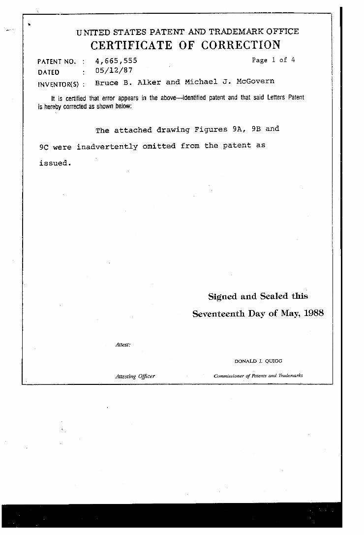
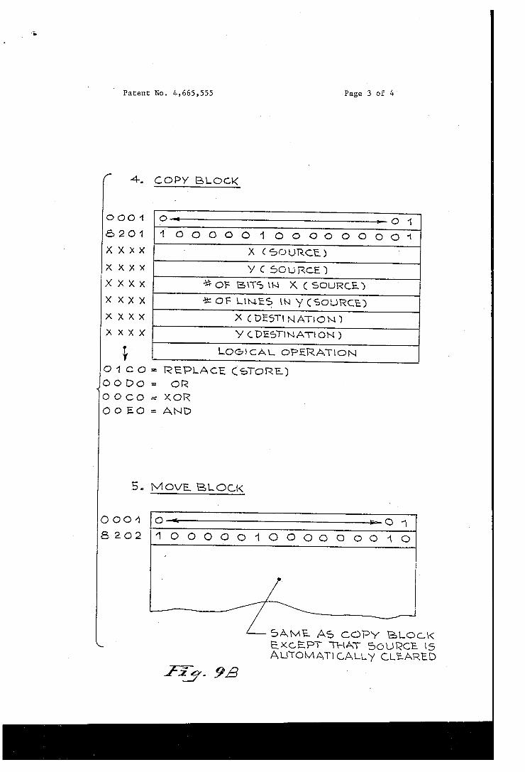
2. DRAW LINE 3. DRAW ARC 4. COPY BLOCK 5. MOVE BLOCK 6. RECTANGLE FILL In order to better understand the meaning of “primi
tive”, attention is directed to the exemplary DRAW LINE primitive which is comprised of nine sixteen bit words (words 0-8) with word 1 de?ning the elementary display instruction, i.e. “DRAW LINE”. Word 2 is shown as de?ning the horizontal value of the starting or origin point and word .3 the vertical value of the same origin point. Word 4 is used to de?ne the horizontal coordinate of the end point and word 5 the vertical coordinate of the end point. Word 6 is used to de?ne a logical operation, e.g. exclusive OR. Additional bits are used to de?ne miscellaneous information including line width, quadrant and slope of the line to be drawn. The assumed microprocessor 106, i.e. MOTOROLA
68000, has a sixteen bit wide bus. Thus, the nine words associated with the exemplary DRAW LINE primitive are communicated along the bus as nine successive words. In a typical embodiment of the invention, the cache and store module 124 is capable‘ of storing 2000 words, i.e. 4000 bytes, on a ?rst-in/?rst-out (FIFO) basis.
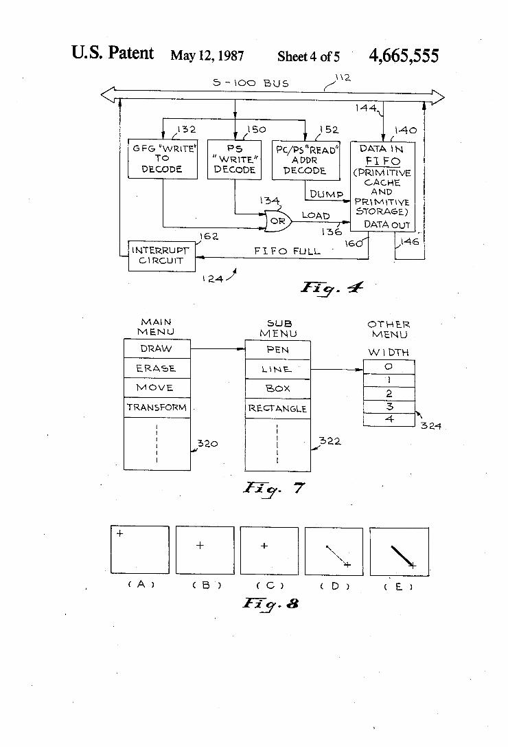
In order to better understand the functioning of the cache and store module 124, attention is directed to FIG. 4 which depicts the module 124 in greater detail. During operation in the DRAWING REVISION MODE, the microprocessor 106 will, in response to operator initiated commands, produce a sequence of primitives addressed to the graphics function generator 62, which are supplied along bus 112. These primitives include a subgroup of display primitives which are spe cially tagged (i.e. uniquely addressed) for caching by the module 124. Microprocessor 106 may produce other primitive addressed to function generator 62 which are for control purposes and need not be cached. Decoder 132 of module 124 recognizes the specially addressed primitives and enables, via OR logic 134, the LOAD control terminal 136 of the array 140. When so enabled, the array 140 will accept data from the bus 112 via data input terminal 144. The array 140 operates in a First in/?rst-out (FIFO) fashion and has a data output termi nal 146 coupled to the bus 112. Whereas the decoder 132 operates during the
DRAWING REVISION MODE to cache primitives produced by microprocessor 106, decoder 150 operates during the DRAWING REDISPLAY MODE to rec ognize a group of primitives, generally comprising a drawing REVISION LEVEL for storage in array 140. That is, as will be discussed hereinafter, in the course of retrieving previously stored groups of primitives from mass storage unit 14 associated as a drawing REVI SION LEVEL, the groups will be accessed from mass storage unit 14 and loaded via bus 112 and input termi» nal 144 into the array 140. A further decoder 152 is provided to recognize an
instruction from the microprocessor 106 to read out a group of primitives from the array 140 at the end of a revisory session. That is, a. group of primitives cached in the array 140, as a consequence of operation in the DRAWING REVISION MODE, are associated to gether and placed on the bus 112 for storage in the mass storage unit 14. In so doing, each such group of primi tives, comprising a REVISION LEVEL, is linked by appropriate header information to a related drawing or

4,665,555 more precisely a particular data set associated with the related drawing.
It should also be noted that the First-in/first-out array 140 depicted in FIG. 4 is provided with an output con trol terminal 160 which indicates when the array is full. In this event, interrupt circuit 162 is actuated to supply an interrupt via bus 112 to microprocessor 106.
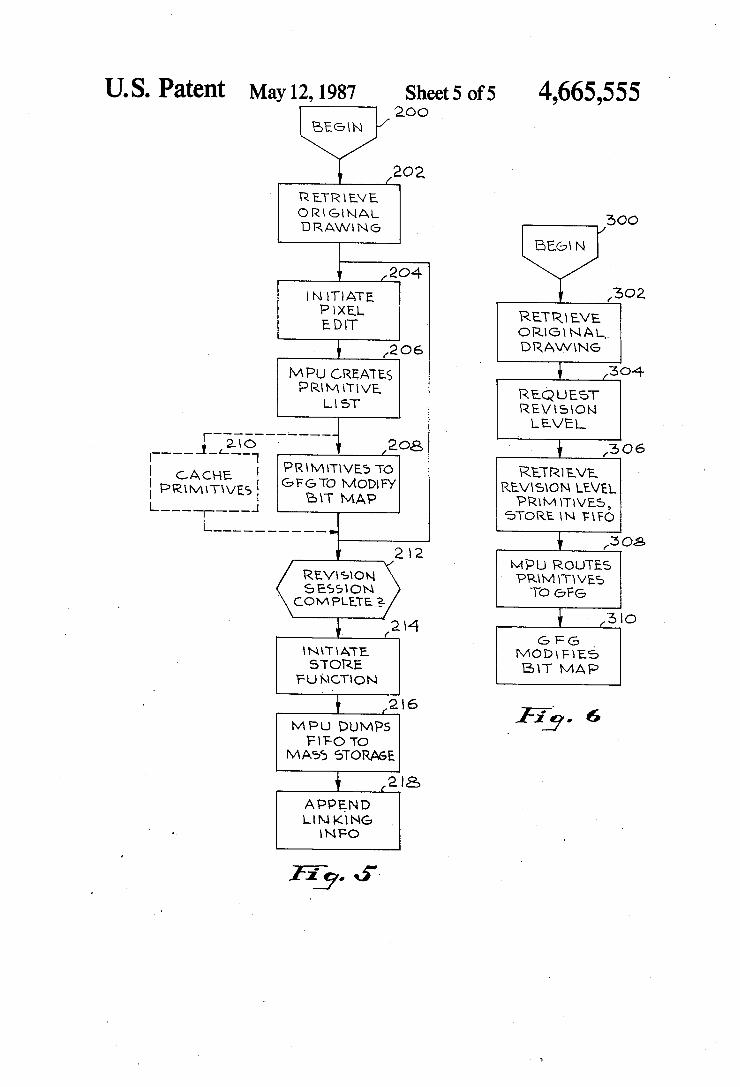
Attention is not directed to FIG. 5 which comprises a flow chart describing system operation in the DRAW
- ING REVISION MODE. The drawing revisory ses sion is initiated by an operator, represented by block 200, by appropriate keyboard commands. The operator will then identify a drawing stored in mass storage and the digital data set related to that drawing will be re trieved and expanded to produce the appropriate bit map in the “pan” memory array 100. This operation is depicted by block 202 in FIG. 5. The data flow required for operation 202 is from the mass storage unit 14 to the host CPU 12 to channel interface module 72 to the data expansion module 68 to the “pin” memory array 100 to the graphic display controller 104 and then to the moni tor 52. As previously pointed out, the monitor display an area of an A size drawing, i.e. l/ 16th of the E size drawing which can be fully represented by the bit map, stored in the “pan” memory array 100. By using the keyboard/pointer 50, the operator can effectively scroll the full drawing represented by the bit map past the monitor window. Block 204 in FIG. 5 represents the operator initiating a pixel edit function, which may for example be selected from a displayed menu. The edit function selected by the operator involves a data trans fer from the keyboard/pointer unit 50 to microcom puter 70.
In de?ning the edit function, the operator may, for example, command the system to draw a rectangle or circle on the displayed drawing at a location identi?ed by the operator by use of the keyboard/pointer 50. The microcomputer 70 then creates a list of primitives as is exempli?ed by the items in Table 3 (FIGS. 9A, 9B, 9C). This action by microcomputer 70 is represented by block 206. P Microcomputer 70 then generates a com mand to transfer the primitive list to the graphic func tion generator 62, via bus 112, “pan” memory data path 102, and bus 64. This action is represented by block 208 and further calls for the graphics function generator 62 to modify the bit map stored in the memory array 100 to execute the revision commanded by the operator. That is, by appropriately modifying the bit map in the mem ory array 100, the graphic display controller 104 will correspondingly modify the drawing displayed by the monitor 52.
In accordance with an important aspect of the inven tion, the cache and store module 124 will respond to the primitive list transfer represented by block 208 to cache those primitives tagged by microprocessor 106. This action, represented by block 210, occurs in parallel with the operations represented by block 208 in a manner which is transparent to the operator.
After the execution of blocks 208 and 210, if the oper ator has not completed the revisory session, then opera tion loops back to block 204. However, after decision block 212 detects the end of a revisory session, as indi cated by an operator input a command will be sent from the keyboard/pointer 50 to the microprocessor 70 (block 214). Microcomputer 70 will thereafter issue an instruction to cause decoder 152 to read out the con tents (i.e. group of primitives) of the first-in/?rst-out array 140 to the host CPU 12 for storage in the mass
20
25
30
35
45
55
60
65
10 storage unit 14. In storing a group of primitives read out. of array 140, the host CPU 12 will append a REVI SION LEVEL designation and also information linking each such REVISION LEVEL to a particular underly ing drawing. This, a header for a data set containing a group of primitives resulting from a single revisory session will include an identi?cation of the underlying drawing, e. g. drawing 000001 and REVISION LEVEL A. This action by the host CPU 12 is represented by block 218. As is well known in the art, the mass storage unit can also store a directory indicating relationships between stored data sets.
Attention is now directed to FIG. 6 which comprises a ?ow chart depicting operation during the DRAW ING REDISPLAY MODE. The DRAWING REDIS PLAY MODE is initiated by the operator via a key board input represented by block 300. By initiating this operational mode and designating the drawing to be displayed, the data set describing that drawing will be retrieved from mass storage unit 14 to modify the bit map in memory array 100 to thus cause the monitor to display the drawing (block 302). The operation repre sented by block 302 corresponds to that represented by block 202 in FIG. 5.
Thereafter, the operator can request any stored RE VISION LEVELS for the drawing displayed by the monitor. This is, in response to an appropriate keyboard input, the microcomputer 70 will command the host CPU 12 to retrieve the desired REVISION LEVEL, i.e. group of primitives, from the mass storage unit 14. This operation is represented by block 304.
In response, the host CPU 12 retrieves the appropri ate REVISION LEVEL and transfers the primitives thereof to the First-in/?rst-out array 140 via decoder 150. This operation is represented by block 306. With the primitives of the desired REVISION LEVEL stored in the array 140, the microcomputer 70 will read the primitives out sequentially and route them via bus 112, and data path module 102 to the graphics function generator 62 (block 308). The graphics function genera tor 62 will then respond to revise the bit map stored in the memory array 100 (block 310) to modify the dis played drawing.
In order to better understand the use of the system by an operator to revise a displayed drawing, attention is directed to FIGS. 7 and 8 which depict an exemplary monitor presentation for performing a DRAW LINE revision. FIG. 7 depicts three exemplary menus which are successively displayed to the operator. More partic ularly, a main menu 2 is depicted which gives the opera tor choices of the following commands: DRAW, ERASE, MOVE, TRANSFORM, etc. By utilizing the aforementioned pointing devices, i.e. mouse or graphic tablet, the user is able to designate the DRAW com mand, for example. The system will then respond by displaying menu 322 which offers: PEN, LINE, BOX, RECTANGLE, etc. The operator can then select, for example, the LINE entry which produces the next menu 324 which prompts the operator to select a line width.
Attention is now called to FIG. 8 which depicts suc cessive monitor screens which would appear to the operator in the course of his performing a DRAW LINE operation. In response to the operator’s selection of the DRAW and LINE options in the menus of FIG. 7, a cursor will appear on the screen as depicted in FIG. 8A. By utilizing the aforementioned pointing device, the operator can move the cursor to an origin or point

4,665,555 11
at which he or she wants the line to start. This is repre sented in FIG. 8B. The operator will then press an action button (e.g. on the mouse) to thereby ?x the origin of the line as depicted by FIG. 8C. The operator will then move the cursor to the end point of the line. This is depicted by FIG. 3D which also shows that the screen displays a rubber band like line trailing the cur sor from the origin point. When the operator positions the cursor from the origin point, he or she will again press the action button to cause the system to draw a solid line of speci?ed width between the origin point and the end point, as depicted in FIG. 8E. To enable the system to present the display screens
depicted in FIG. 8, the microprocessor 106 generates a series of primitives which address the graphics function generator 62 to cause it to modify the bit map within the “pan” memory array 100. Thus, for example, micro processor 106 generates a COPY BLOCK primitive to move the cursor onto the screen as depicted in FIG. 8A. As the operator moves the cursor into position at the
desired origin point, the microprocessor 106 will issue many COPY BLOCK primitives designating exclusive OR logical operations, to remove each previously dis played cursor so that only a single cursor is displayed at a time. When the operator presses the action button to ?x the
origin of the line, as depicted by FIG. 8C, the micro processor 106 will generate the DRAW POINT primi tive. As the operator then moves the cursor from the origin point to the line end point, as depicted by FIG. 8D, many COPY BLOCK primitives will be generated to successively remove or erase each previously dis placed cursor. Additionally, many DRAW LINE prim itive will be generated to create the aforementioned rubber band effect connecting the ?xed origin point with the moving cursor. These DRAW LINE primi tives occur in pairs with an exclusive OR operation being used to remove a previous line as each new line is displayed. When the action button is depressed to draw a solid
line between the origin point and line end, as depicted in FIG. 8B, a DRAW LINE primitive is generated by the microprocessor 106 which causes the line of speci?ed width to be drawn. It is that last DRAW LINE primi tive which is specially addressed by the microprocessor 106 so that in addition to causing the graphic function generator 62 to modify the bit map in the pan memory array 100, it also caches the DRAW LINE primitive in the cache and store module 124. From the foregoing, it should now be understood that
a system has been disclosed herein for ef?ciently stor ing, revising, and redisplaying drawings. By originally storing the raw pixel data in highly compressed binary form, many thousands of drawings can be reasonably stored in available mass storage units (see Table 2). This compressed binary data is expanded when accessed to produce a bit map in the PAN memory for controlling the display monitor. Revisory data is ef?ciently stored by utilizing a cache memory for automatically storing primitives and associating one or more primitives as a designated REVISION LEVEL linked to an underly» ing drawing. In the REDISPLAY MODE, these primi= tives, which represent a highly compressed form of pixel data, are retrieved from mass storage and utilized to modify the bit map currently in PAN memory 100. Accordingly, it should now be understood that in con trast to prior approaches which store data sets repre senting the latest revision of a drawing, a system in
H LII
25
35
45
55
60
65
12 accordance with the present invention retains data sets in compressed binary form representing the pixel data in the original drawing and in addition revisory pixel data in the form of primitives of each REVISION LEVEL. When the latest revision of a drawing is desired, the original drawing is accessed and then each REVISION LEVEL is accessed in sequence to thus successively modify the displayed drawing frame by frame in incre mental or cinematic fashion. We claim: 1. A system suitable for electronically storing, revis
ing, and displaying technical drawings comprising: mass storage means for storing multiple data sets,
each data set comprising digital data de?ning a pixel representation of a different technical draw ing;
operator input means for enabling an operator ‘to selectively identify a data set stored in said mass storage means;
monitor means for displaying a drawing; and control means responsive to said operator input means for controlling said monitor means to dis play at least a portion of the drawing identi?ed by said input means, said control means including:
pixel memory means for storing a bit map of a draw ing;
processor means for retrieving each data set identi ?ed by said operator input means and responsive to the digital data therein for loading a bit map into said pixel memory means;
means responsive to said bit map stored in said pixel memory means for causing said monitor to display pixels representing the identi?ed drawing;
said operator input means including means enabling an operator to de?ne a DRAWING REVISION MODE and to initiate the generation of primitives, each primitive de?ning an elementary display in struction and related parameter data;
said processor means including means reponsive to each of said generated primitives for revising said bit map stored in said pixel memory means; and
cache means for temporarily storing each of said generated primitives.
2. The system of claim 1 further including means for grouping primitives stored in said cache means as a designated revision level; means for storing each revision level primitive group
in said mass storage means; and means for- storing linking information associating
each revision level primitive group with one of said drawings.
3. The system of claim 2 wherein said operator input means includes means enabling an operator to de?ne a DRAWING REDISPLAY MODE; means active during said DRAWING REDISPLAY MODE for retrieving from said mass storage means revision level primitive groups associated with the drawing concurrently displayed by said monitor; and wherein '
said processor means includes means for revising said bit map stored in said pixel memory means in re sponse to each revision level primitive group re- 7 trieved from said mass storage means.
4. The system of claim 3 wherein said means for revis ing said bit map operates in an incremental manner, whereby said monitor displays in sequence an identi?ed drawing and subsequent revision levels of that drawing.

4,665,555 13
5. The system of claim 2 wherein each of said data sets de?ning a technical drawing is stored as com pressed binary data in said mass storage means; and wherein
said processor means includes means for expanding the compressed binary data for producing said bit map.
6. The system of claim 2 wherein said processor means includes:
control means including 'a' microprocessor and a data/control bus coupled thereto;
means coupling said operator input means to said control means microprocessor;
graphic function generator means for producing and revising said bit map;
means for coupling said graphic function generator means to said data/control bus whereby said con trol means microprocessor generates primitives addressing said function generator means; and wherein
said cache means is coupled to said data/ control bus and is responsive to primitives addressed to said function generator means for automatically storing said primitives.
7. The system of claim 1 wherein said mass storage means comprises an optical storage unit.
8. The system of claim 1 wherein said cache means comprises a ?rst in/ ?rst out read/write memory.
9. A method of storing, displaying and revising exist ing technical drawings comprising:
scanning said drawings to produce a different set of digital data related to each drawing;
15
25
30
35
45
50
55
65
14 storing each of said digital data sets in a mass storage
unit; accessing a selected one of said data sets to produce a
bit map; responding to said bit map to display the drawing
related to said accessed data set; generating binary coded primitives each de?ning a
display instruction and related parameters; responding to said generated primitives to revise said
bit map; grouping selected ones of said generated primitives as
a revision level; storing each revision level primitive group together
with information linking each group with a stored data set; and
retrieving stored revision level groups associated with the same drawing to sequentially revise the displayed drawing one revision level at a time.
10. The method of claim 9 wherein said scanning step includes producing a stream of bits each representative of a different pixel on a drawing; and including the further step of
compressing said bit stream to produce each data set. 11. The method of claim 10 wherein said accessing
step includes expanding the selected data set to produce said bit map.
12. The method of claim 10 wherein said step of stor ing each revision level group comprises storing the primitives thereof in a mass storage unit; and including the further step of;
automatically temporarily storing each of said gener ated primitives in a cache memory.
* k i it ‘I
UNITED STATES PATENT AND TRADEMARK OFFICE
CERTIFICATE OF CORRECTION PATENT NO. I 4,665,555 Page 1 of 4
DATED ; 05/12/87 '
|NVENTQR(S) ; Bruce B. Alker and Michael J. McGovern
It is certified that error appears in the above-identified patent and that said Letters Patent is hereby corrected as shown below:
The attached drawing Figures 9A, 9B and
9C were inadvertently omitted from the patent as
issued.
Signed and Sealed this
Seventeenth Day of May, 1988
Arrest:
DONALD J. QUIGG
Arresting O?icer ' Commissioner of Patents and Trademarks

i)
' Patent No. 4,665,555 Page 2 of 4
‘l. DRAW POINT
MS! I l l I I lzsl'rlelsldrla'lzl\I0IWRHTE 0001 O A > O 1 COMMAND
8%01 1000OOO1000OOOO1GRAPHKL,
XXXX 4-—————Y ORIG)N
NOTE‘. RE6\$TER L6 \5 USED To DETERM\NE. Loc-ncAL OPERATION (Ce, xoR, SET...’ CLEAR). REGXSTER WX IS USED TO DETERMINE THE. 1* OF PomTs To DRAW m x
2.DRAW LiNE
* — WRFYE 0001 O *0 1 COMMAND
8102 1000000100000001 GRAPHxQ XXXX " ' ' X OR\G71N DRAW UNEC
' ~ ~ ' \/ ORKStN '
é ' X ENDPomT XXXX Y END Pom'r : wag
o xxo LOelcAL OPERATION
X XOX LINE WHDTH RESV’D QUAD ‘
XXXX SLOPE 0R dx/dy
aw WRWE
0001 04 :01 COMMAND
810/4 10000001000001006RAP\~\\0, x X X>X ‘ X CENTER DRAW ARcc,
4 \/ CENTER
' \x x x x LOGKZAL OPERATDN 9A
' Patent
(4. O O O 4
$201
XXXX
XXXx
XXXX
XXXX
X X X X
X X X X
L O1CO
JooDo OOCO OOE-O
COO’! 8202
No. 4,665,555 Page 3 of 4
COPY BLOCK
0 4 >_ O 1
1OOOOO1OOOOOOOO'1 X C 5OURCE.)
\/ C souRcE)
? OF arm “4 X C SOURCE)
<3: OF Lam-=5 m y (SOURCE)
X C DESTl NATION)
Y c DESTlN AT! ON)
LOG) CAL OPERA'HON
ll REDLACE C€>TORE) 012 XOR AND
Jl
II
M OVE. BL OCK
04 >6 1
4000OO1OQOOOOO1O
SAME. A5 COPY BLOQK EXCEPT THAT BOUQCE {5 AUTOMATICALLY CLEARED
iii- 95