Computer Architecture and Programming -...
57
Henri Casanova ([email protected]) ICS312 Machine-level and Systems Programming Computer Architecture and Programming
Transcript of Computer Architecture and Programming -...

Henri Casanova ([email protected])
ICS312Machine-level and
Systems Programming
Computer Architecture and Programming

“Computer Architecture”? The field of Computer Architecture is about the
fundamental structure of computer systems What are the components How are they interconnected? How fast does the whole system operate? How much power does it consume? How much does it cost to mass-produce? How to achieve desired speed/power/cost trade-offs?
The conceptual model for computer architecture, that hasn’t fundamentally changed since 1965: the Von-Neumann architecture
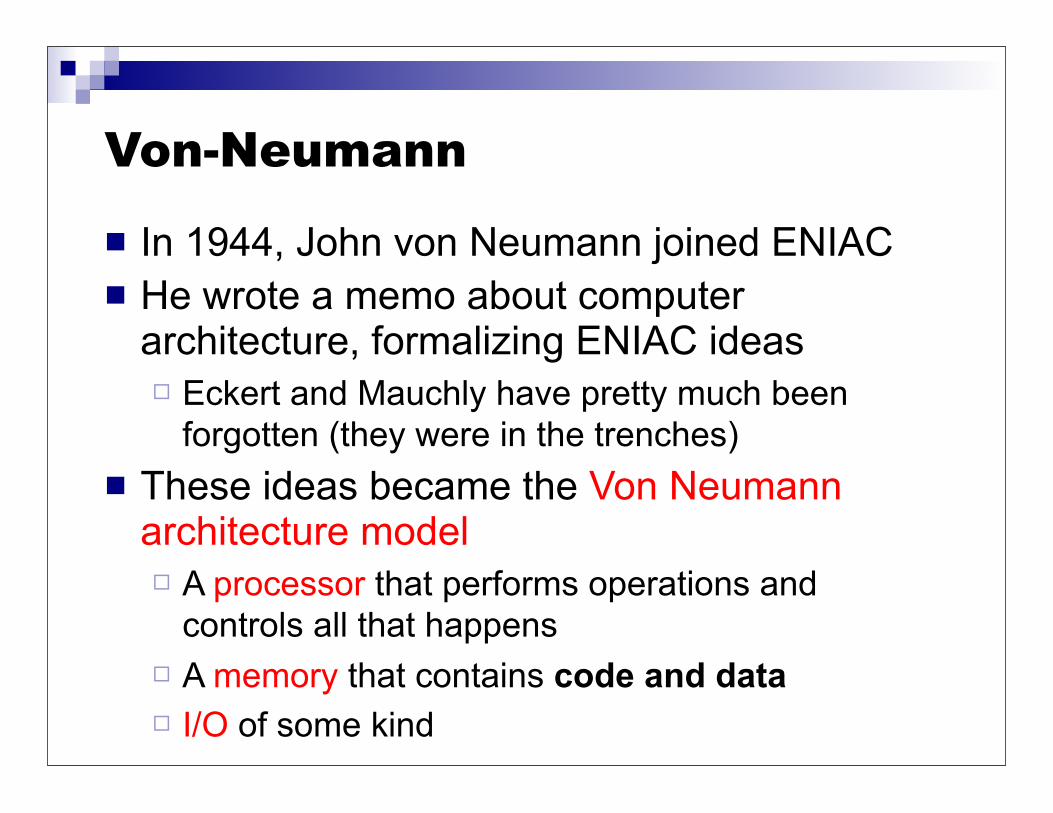
Von-Neumann
In 1944, John von Neumann joined ENIAC He wrote a memo about computer
architecture, formalizing ENIAC ideas Eckert and Mauchly have pretty much been
forgotten (they were in the trenches) These ideas became the Von Neumann
architecture model A processor that performs operations and
controls all that happens A memory that contains code and data I/O of some kind

Von-Neumann Model
Amazingly, it’s still possible to think of the computer this way at a conceptual level (model from ~70 years ago!!!)
But a computer today doesn’t look quite like this
CPU Memory
I/OSystem

Data Stored in Memory All “information” in the computer is in binary form
Since Claude Shannon’s M.S. thesis in the 30’s 0: zero voltage, 1: positive voltage (e.g., 5V) bit: the smallest unit of information (0 or 1)
The basic unit of memory is a byte 1 Byte = 8 bits, e.g., “0101 1101” 1 KiB = 210 byte = 1,024 bytes 1 MiB = 210 KiB = 220 bytes (~ 1 Million) 1 GiB = 210 MiB = 230 bytes (~ 1 Billion) 1 TiB = 210 GiB = 240 bytes (~ 1 Trillion) 1 PiB = 210 TiB = 250 bytes (~ 1000 Trillion) 1 EiB = 210 PiB = 260 bytes (~ 1 Million Trillion) ...
Note the “i” in the notations above: means “power of 2”

Data Stored in Memory Each byte in memory is labeled by a unique address An address is a number which identifies the memory location
of each byte in memory e.g., the byte at address 3 is 00010010 e.g., the byte at address 241 is 10110101
Typically, we write address in binary as well e.g., the byte at address 00000011 is 00010010 e.g., the byte at address 11110001 is 10110101
All addresses in the machine have the same number of bits e.g., 8-bit addresses
The processor has instructions that say “Read the byte at address X and give me its value” and “Write some value into the byte at address X”

Conceptual View of Memoryaddress content
0000 0000 0000 0000 0110 11100000 0000 0000 0001 1111 01000000 0000 0000 0010 0000 00000000 0000 0000 0011 0000 00000000 0000 0000 0100 0101 11100000 0000 0000 0101 1010 11010000 0000 0000 0110 0000 00010000 0000 0000 0111 0100 00000000 0000 0000 1000 1111 0101
... ...
At address 0000 0000 0000 0010 the content is 0000 0000

Conceptual View of Memoryaddress content
0000 0000 0000 0000 0110 11100000 0000 0000 0001 1111 01000000 0000 0000 0010 0000 00000000 0000 0000 0011 0000 00000000 0000 0000 0100 0101 11100000 0000 0000 0101 1010 11010000 0000 0000 0110 0000 00010000 0000 0000 0111 0100 00000000 0000 0000 1000 1111 0101
... ...
At address 0000 0000 0000 0100 the content is 0101 1110

Both Code and Data in Memory
Memory
0010 00010000 1110
1111 00001000 0000
... ...
Address Value
0000 1100 0110 1011
0000 1101 1111 0010
0101 11111111 0010
... ...
Code
Data
Once a program is loaded in memory, its address space contains both code and data
To the CPU those are not really different, but the programmer knows which bytes are data an which are code Always conveniently
hidden from you if you’ve never written assembly
But we’ll have to keep code/data straight in these lecture notes
Example Address Space

We need a CPU So now we have a memory in which we can store/retrieve
bytes at precise location These bytes presumably have some useful meaning to us
e.g., integers, ASCII codes of characters, floating points numbers, RGB values
e.g., instructions that specify what to do with the data; when you buy a processor, the vendor defines the instruction set (e.g., instruction “0010 1101” means “increment some useful counter”)
The CPU is the piece of hardware that modifies the content of memory In fact, one can really think of the CPU as a device that takes
use from on memory state (i.e, all the stored content) to another memory state (some new, desired stored content)

What’s in the CPU?
Memory
I/OSystem
CPU

What’s in the CPU?
Memory
I/OSystem
ControlUnitALU
Program counter register
register
registercurrent instruction

What’s in the CPU?
ControlUnitALU
Program counter register
register
register
Registers: the “variables” that hardware instructions work with
Data can be loaded from memory into a registerData can be stored from a register back into memoryOperands and results of computations are in registersAccessing a register is really fastThere is a limited number of registers
current instruction

What’s in the CPU?
ControlUnitALU
Program counter register
register
register
Arithmetic and Logic Unit: what you do computation with
used to compute a value based on current register values and store the result back into a register
+, *, /, -, OR, AND, XOR, etc.
current instruction
What’s in the CPU?
ControlUnitALU
Program counter register
register
register
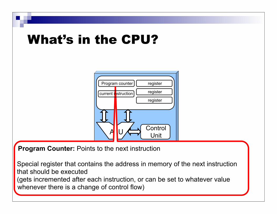
Program Counter: Points to the next instruction
Special register that contains the address in memory of the next instruction that should be executed (gets incremented after each instruction, or can be set to whatever value whenever there is a change of control flow)
current instruction

What’s in the CPU?
ControlUnitALU
Program counter register
register
register
Current Instruction: Holds the instruction that’s currently being executed
current instruction

What’s in the CPU?
ControlUnitALU
Program counter register
register
register
Control Unit: Decodes instructions and make them happen
Logic hardware that decodes instructions (i.e., based on their bits) and sends the appropriate (electrical) signals to hardware components in the CPU
current instruction
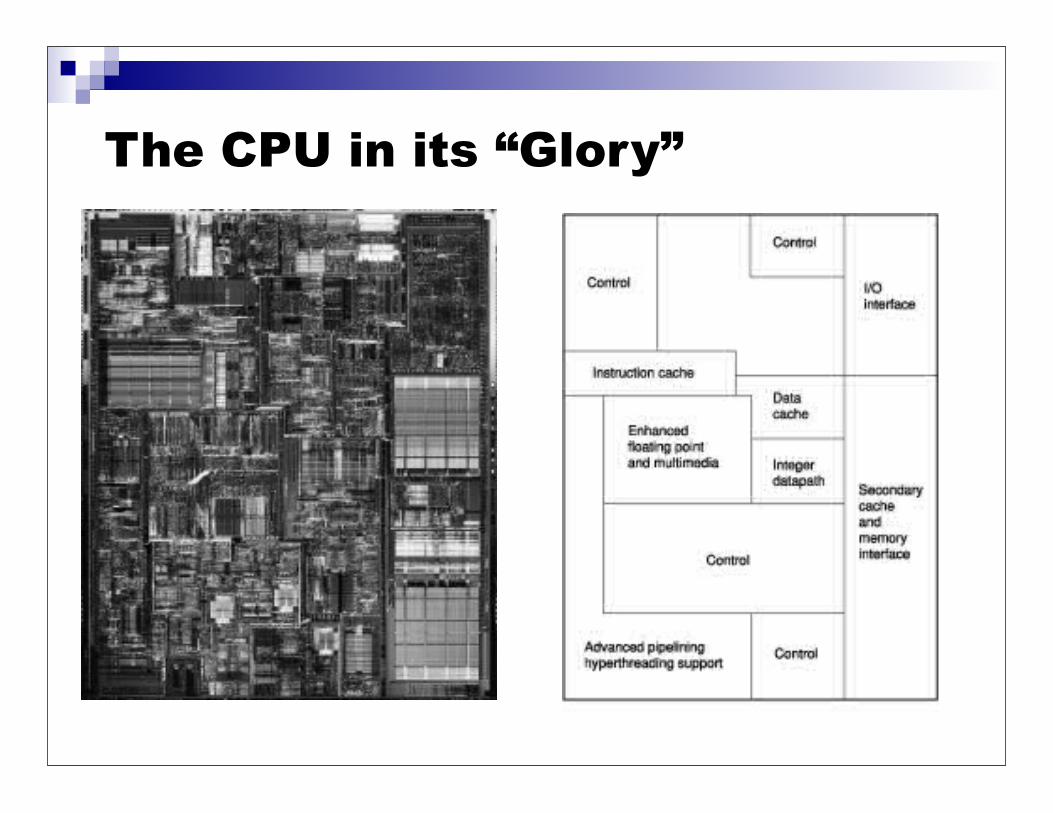
The CPU in its “Glory”
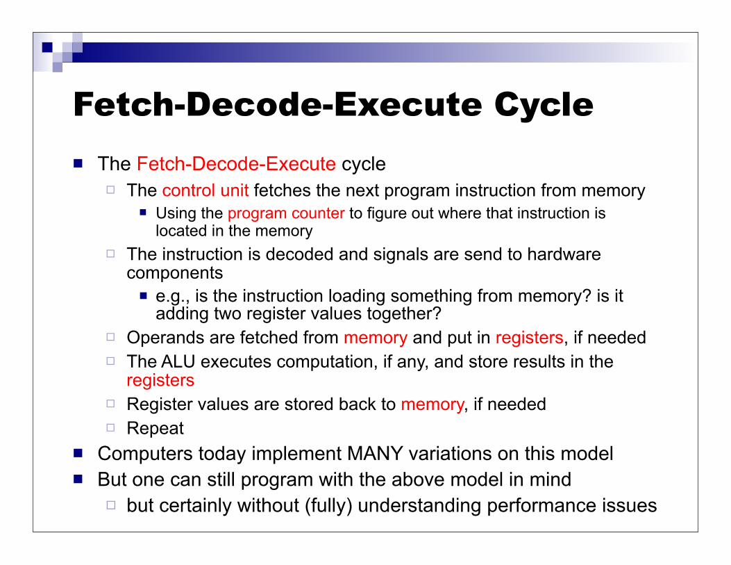
Fetch-Decode-Execute Cycle The Fetch-Decode-Execute cycle
The control unit fetches the next program instruction from memory Using the program counter to figure out where that instruction is
located in the memory The instruction is decoded and signals are send to hardware
components e.g., is the instruction loading something from memory? is it
adding two register values together? Operands are fetched from memory and put in registers, if needed The ALU executes computation, if any, and store results in the
registers Register values are stored back to memory, if needed Repeat
Computers today implement MANY variations on this model But one can still program with the above model in mind
but certainly without (fully) understanding performance issues
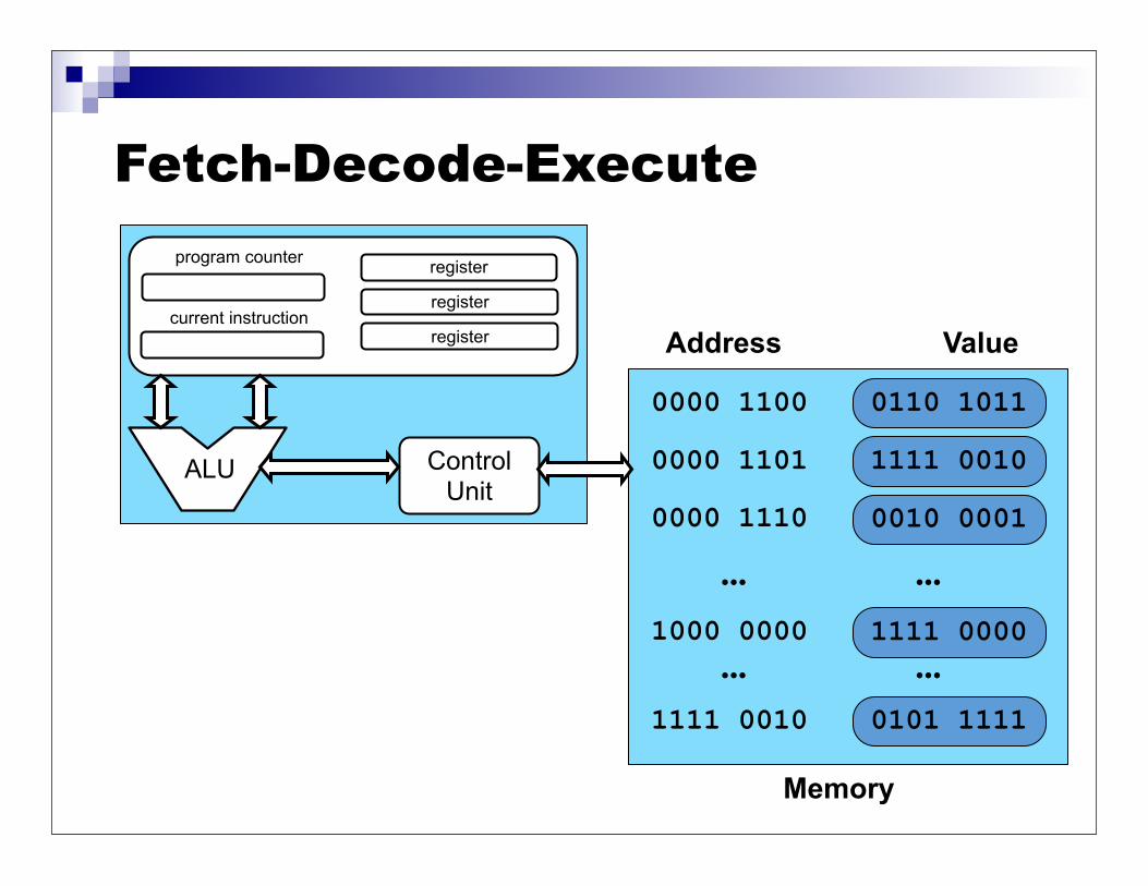
Fetch-Decode-Execute
Memory
0010 00010000 1110
1111 00001000 0000
... ...
Address Value
0000 1100 0110 1011
0000 1101 1111 0010
0101 11111111 0010
... ...
ControlUnit
ALU
register
register
register
program counter
current instruction

Fetch-Decode-Execute
Memory
0010 00010000 1110
1111 00001000 0000
... ...
Address Value
0000 1100 0110 1011
0000 1101 1111 0010
0101 11111111 0010
... ...
ControlUnit
ALU
0000 1100register
register
register
program counter
current instruction
Somehow, the program counter is initialized to some content, which is an address (we’ll see how that happens much later)

Fetch-Decode-Execute
Memory
0010 00010000 1110
1111 00001000 0000
... ...
Address Value
0000 1100 0110 1011
0000 1101 1111 0010
0101 11111111 0010
... ...
ControlUnit
ALU
0000 1100register
register
register
program counter
Fetch the content (instruction) at address 0000 1100, which is “0110 1011”, and store it in the “current instruction” register
current instruction0110 1011

Fetch-Decode-Execute
Memory
0010 00010000 1110
1111 00001000 0000
... ...
Address Value
0000 1100 0110 1011
0000 1101 1111 0010
0101 11111111 0010
... ...
ControlUnit
ALU
0000 1101register
register
register
program counter
Increment the program counter
current instruction0110 1011
Fetch-Decode-Execute
Memory
0010 00010000 1110
1111 00001000 0000
... ...
Address Value
0000 1100 0110 1011
0000 1101 1111 0010
0101 11111111 0010
... ...
ControlUnit
ALU
0000 1101register
register
register
program counter
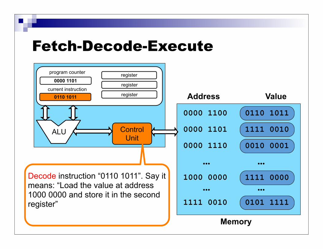
Decode instruction “0110 1011”. Say it means: “Load the value at address 1000 0000 and store it in the second register”
current instruction0110 1011

Fetch-Decode-Execute
Memory
0010 00010000 1110
1111 00001000 0000
... ...
Address Value
0000 1100 0110 1011
0000 1101 1111 0010
0101 11111111 0010
... ...
ControlUnit
ALU
0000 1101register
1111 0000
register
program counter
Send signals to all hardware components to execute the instruction: load the value at address 1000 0000, which is “1111 0000” and store it in the second register
current instruction0110 1011
Fetch-Decode-Execute
Memory
0010 00010000 1110
1000 0000
... ...
Address Value
0000 1100 0110 1011
0000 1101 1111 0010
0101 11111111 0010
... ...
ControlUnit
ALU
0000 1101register
1111 0000
register
program counter
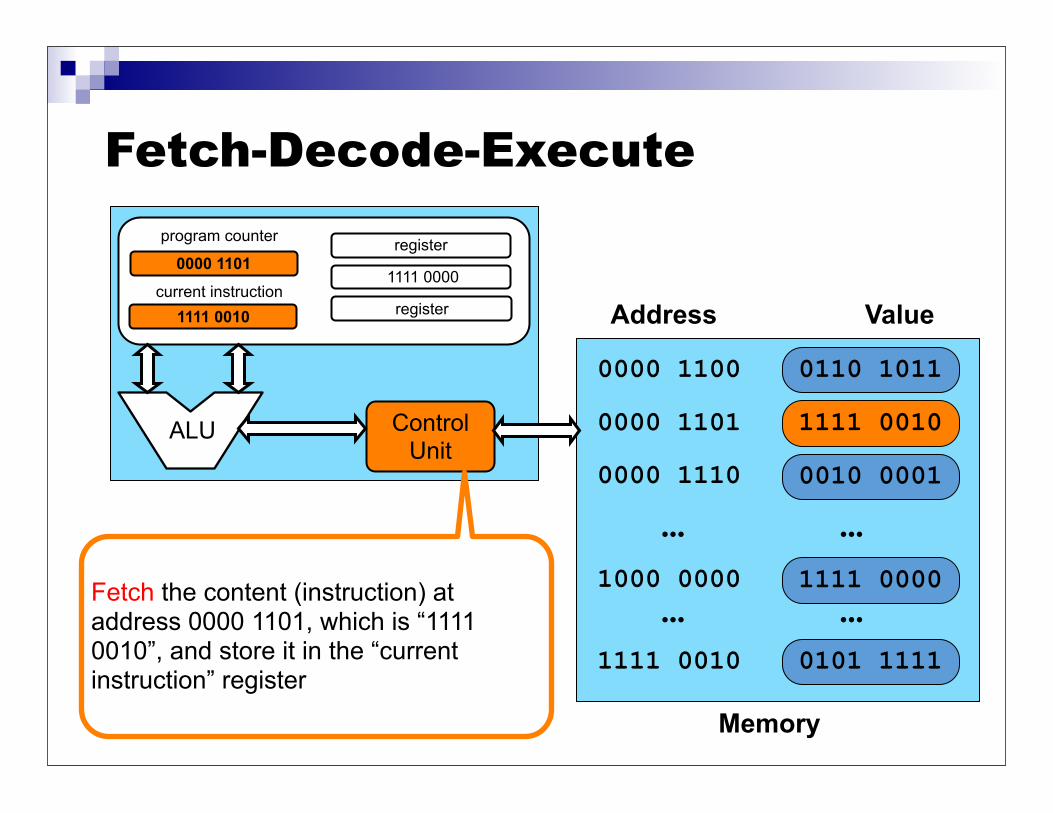
Fetch the content (instruction) at address 0000 1101, which is “1111 0010”, and store it in the “current instruction” register
current instruction1111 0010
1111 0000

Fetch-Decode-Execute
Memory
0010 00010000 1110
1111 00001000 0000
... ...
Address Value
0000 1100 0110 1011
0000 1101 1111 0010
0101 11111111 0010
... ...
ControlUnit
ALU
0000 1110register
register
program counter
Increment the program counter
current instruction1111 0010
1111 0000

Fetch-Decode-Execute
Memory
0010 00010000 1110
1111 00001000 0000
... ...
Address Value
0000 1100 0110 1011
0000 1101 1111 0010
0101 11111111 0010
... ...
ControlUnit
ALU
0000 1110register
register
program counter
current instruction1111 0010
1111 0000
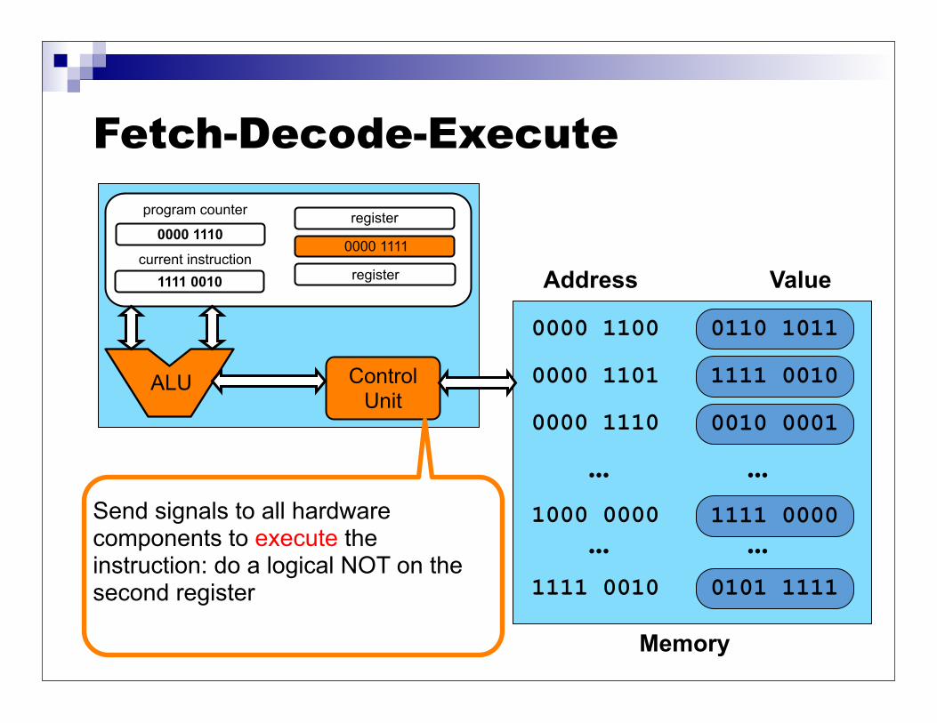
Decode instruction “1111 0010”. Say it means: “Do a logical NOT on the second register”
Fetch-Decode-Execute
Memory
0010 00010000 1110
1111 00001000 0000
... ...
Address Value
0000 1100 0110 1011
0000 1101 1111 0010
0101 11111111 0010
... ...
ControlUnit
ALU
0000 1110register
register
program counter
current instruction1111 0010
0000 1111
Send signals to all hardware components to execute the instruction: do a logical NOT on the second register

Fetch-Decode-Execute
Memory
0010 00010000 1110
1000 0000
... ...
Address Value
0000 1100 0110 1011
0000 1101
0101 11111111 0010
... ...
ControlUnit
ALU
0000 1110register
0000 1111
register
program counter
Fetch the content (instruction) at address 0000 1110, which is “0010 0001”, and store it in the “current instruction” register
current instruction0010 0001
1111 0000
1111 0010

Fetch-Decode-Execute
Memory
0000 1110
1000 0000
... ...
Address Value
0000 1100 0110 1011
0000 1101
0101 11111111 0010
... ...
ControlUnit
ALU
0000 1111register
0000 1111
register
program counter
current instruction0010 0001
1111 0000
1111 0010
Increment the program counter
0010 0001

Fetch-Decode-Execute
Memory
0000 1110
1000 0000
... ...
Address Value
0000 1100 0110 1011
0000 1101
0101 11111111 0010
... ...
ControlUnit
ALU
0000 1111register
0000 1111
register
program counter
current instruction0010 0001
1111 0000
1111 0010
0010 0001
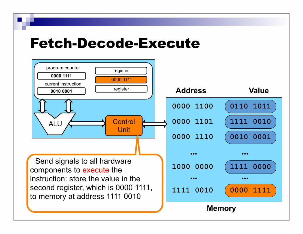
Decode instruction “0010 0001”. Say it means: “Store the value in the second register to memory at address 1111 0010”
Fetch-Decode-Execute
Memory
0000 1110
1000 0000
... ...
Address Value
0000 1100 0110 1011
0000 1101
0000 11111111 0010
... ...
ControlUnit
ALU
0000 1111register
0000 1111
register
program counter
current instruction0010 0001
1111 0000
1111 0010
0010 0001
Send signals to all hardware components to execute the instruction: store the value in the second register, which is 0000 1111, to memory at address 1111 0010
Fetch-Decode-Execute This is only a simplified view of the way things work The “control unit” is not a single thing
Control and data paths are implemented by several complex hardware components
There are multiple ALUs, there are caches, there are multiple CPUs in fact (“cores”)
Execution is pipelined: e.g., while one instruction is fetched, another is executed
Decades of computer architecture research have gone into improving performance, thus often leading to staggering hardware complexity Doing smart things in hardware requires more logic gates and
wires, thus increasing processor cost But conceptually, fetch-decode-execute is it

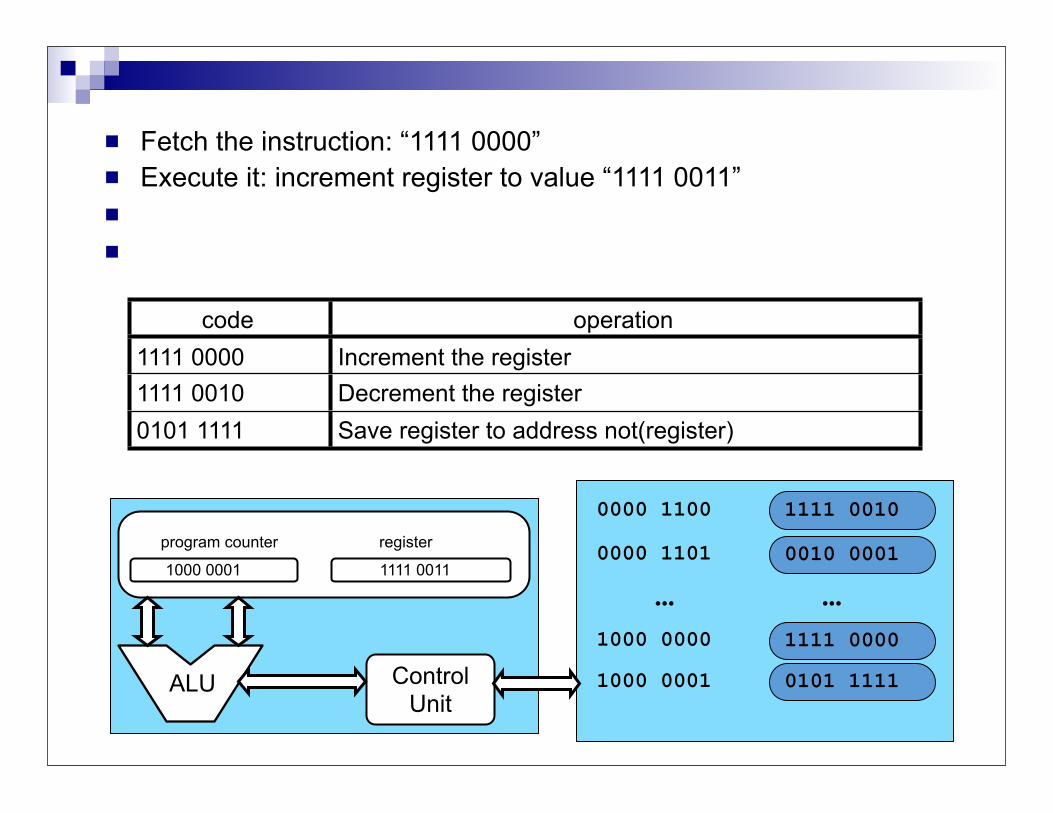
In-Class Exercise With the following instruction set definition and machine state,
what is the new memory state after execution completes?
0010 00010000 1101
1111 00001000 0000
... ...
0000 1100 1111 0010
0101 11111000 0001ControlUnit
ALU
program counter
1000 0000
code operation1111 0000 Increment the register1111 0010 Decrement the register0101 1111 Save register to address not(register)
1111 0010
register
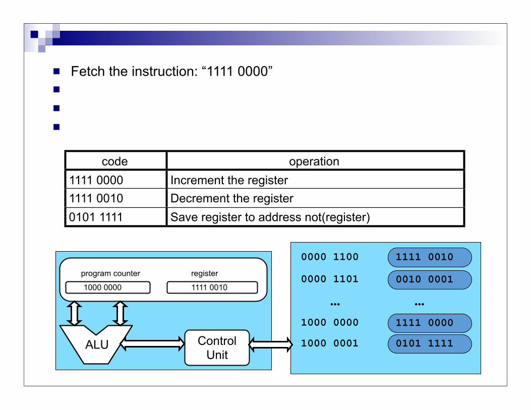
Fetch the instruction: “1111 0000” Execute it: increment register to value “1111 0011” Fetch the next instruction: “1111 0001” Execute it: save value “1111 0011” to address “0000 1100”
0010 00010000 1101
1111 00001000 0000
... ...
0000 1100 1111 0010
0101 11111000 0001ControlUnit
ALU
program counter
1000 0000
code operation1111 0000 Increment the register1111 0010 Decrement the register0101 1111 Save register to address not(register)
1111 0010
register
Fetch the instruction: “1111 0000” Execute it: increment register to value “1111 0011” Fetch the next instruction: “1111 0001” Execute it: save value “1111 0011” to address “0000 1100”
0010 00010000 1101
1111 00001000 0000
... ...
0000 1100 1111 0010
0101 11111000 0001ControlUnit
ALU
program counter
1000 0001
code operation1111 0000 Increment the register1111 0010 Decrement the register0101 1111 Save register to address not(register)
1111 0011
register

Fetch the instruction: “1111 0000” Execute it: increment register to value “1111 0011” Fetch the next instruction: “0101 1111” Execute it: save value “1111 0011” to address “0000 1100”
0010 00010000 1101
1111 00001000 0000
... ...
0000 1100 1111 0011
0101 11111000 0001ControlUnit
ALU
program counter
1000 0001
code operation1111 0000 Increment the register1111 0010 Decrement the register0101 1111 Save register to address not(register)
1111 0011
register

The Clock Every computer maintains an internal clock that
regulates how quickly instructions can be executed, and is used to synchronize system components Just like a metronome
In the previous example, each “event” happens at a different “tick” of the clock
The frequency of the clock is called the clock rate The time in between two clock ticks is called a clock
cycle or cycle for short Clock cycle = 1 / Clock Rate
Clock rate = 2.4 GHz Clock cycle = 1 / (2.4*1000*1000*1000) = 0.416 e-9 sec = 0.416 ns (nanosec)

Faster/slower Clock Rate The higher the clock rate, the shorter the clock cycle It’s tempting to think that a faster clock rate means a faster
computer But it all depends of what amount of work is done in a clock cycle!
Computer A: clock rate of 2GHz and a multiplication requires 10 cycles Computer B: clock rate of 1.5GHz and a multiplication requires 5
cycles Computer B is faster than Computer A to run a program that performs a
lot of multiplications Therefore, clock rates should not be used to compare computers in
different families A 1.4GHz Pentium 4 is most likely slower than a 1.5GHz Pentium 4 A 2.4GHz Pentium 4 may be slower than a 2.0GHz AMD Athlon64
Furthermore, comparisons depends on the type of applications Computer A faster than Computer B for some applications Computer B faster than Computer A for some others

Instructions Instructions are encoded in binary machine code
e.g.: 01000110101101 may mean “perform an addition of two registers and store the results in another register”
The CPU is built using gates (OR, AND, etc.) which themselves use transistors See ICS331
These gates implement instruction decoding Based on the bits of the instruction code, several signals are sent to
different electronic components, which in turn perform useful tasks Typically, an instruction consists of two parts
The opcode: what the instruction computes The operands: the input to the computation
opcode operands0 1 0 0 0 1 1 0 1 0 1 1 0 1
Instruction Set Architecture (ISA)
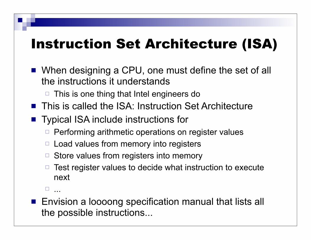
When designing a CPU, one must define the set of all the instructions it understands This is one thing that Intel engineers do
This is called the ISA: Instruction Set Architecture Typical ISA include instructions for
Performing arithmetic operations on register values Load values from memory into registers Store values from registers into memory Test register values to decide what instruction to execute
next ...
Envision a loooong specification manual that lists all the possible instructions...

ISA specification Example: x86
opcode in HEX
what it does
operands
Let’s look at the Web site http://ref.x86asm.net/

Assembly language It’s really difficult for humans to read/remember binary
instruction encodings But people used to do it! One would typically use hexadecimal encoding, but still it
seems impossible to doin today’s world Therefore it is typical to use a set of mnemonics,
which form the assembly language It is often said that the CPU understands assembly language This is not technically true, as the CPU understand machine
code, which we, as humans, choose the represent using assembly language
An assembler transforms assembly code into machine code (i.e., from a human readable format into a binary format that the CPU understands)

Assembly Language It used to be that all computer programmers did all
day was to write assembly code This was difficult for many reasons
Difficult to read Very difficult to debug Different from one computer to another!
The use of assembly language for all programming prevented the (sustainable) development of large software project involving many programmers
This is the main motivation for the development of high-level languages FORTRAN, Cobol, C, etc.

High-level Languages The first successful high-level language was FORTRAN
Developed by IBM in 1954 to run on they 704 series Used for scientific computing
The introduction of FORTRAN led people to believe that there would never be bugs again because it made programming so easy! But high-level languages led to larger and more complex software
systems, hence leading to bugs Another early programming language was COBOL
Developed in 1960, strongly supported by DoD Used for business applications
In the early 60s IBM had a simple marketing strategy On the IBM 7090 you used FORTRAN to do science On the IBM 7080 you used COBOL to do business
Many high-level languages have been developed since then, and they are what most programmers use Fascinating history (see ICS 313)
High-Level Languages
Having high-level languages is good, but CPUs do not understand them As we saw, they only understand very basic
instructions to manipulate registers, etc. Therefore, there needs to be a translation from
a high-level language to machine code The translation is done by a compiler Let’s see this on a picture....

The Big (Simplified) Picture
char *tmpfilename; int num_schedulers=0; int num_request_submitters=0; int i,j;
if (!(f = fopen(filename,"r"))) { xbt_assert1(0,"Cannot open file %s",filename); } while(fgets(buffer,256,f)) { if (!strncmp(buffer,"SCHEDULER",9)) num_schedulers++; if (!strncmp(buffer,"REQUESTSUBMITTER",16)) num_request_submitters++; } fclose(f); tmpfilename = strdup("/tmp/jobsimulator_
High-level code
COMPILER
sll $t3, $t1, 2 add $t3, $s0, $t3
sll $t4, $t0, 2add $t4, $s0, $t4
lw $t5, 0($t3) lw $t6, 0($t4)
slt $t2, $t5, $t6beq $t2, $zero, endifadd $t0, $t1, $zero
sll $t4, $t0, 2add $t4, $s0, $t4
lw $t5, 0($t3) lw $t6, 0($t4)slt $t2, $t5, $t6
beq $t2, $zero, endif
Assembly code
ASSEMBLER
010000101010110110101010101111010101101001010101010001101010101010100101111100001010101001000101010111101011010000000010000100000010001000100011101001010010101011000101010010010101010101010101010101101010101111010101101010101010100101111100001010101001
Machine code
ControlUnitALU
Program counter registerregisterregisterCPU
sll $t3, $t1, 2 add $t3, $s0, $t3
sll $t4, $t0, 2add $t4, $s0, $t4
lw $t5, 0($t3) lw $t6, 0($t4)
slt $t2, $t5, $t6beq $t2, $zero, endif
Hand-writtenAssembly code
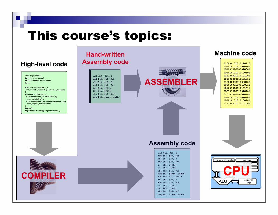
This course’s topics:
char *tmpfilename; int num_schedulers=0; int num_request_submitters=0; int i,j;
if (!(f = fopen(filename,"r"))) { xbt_assert1(0,"Cannot open file %s",filename); } while(fgets(buffer,256,f)) { if (!strncmp(buffer,"SCHEDULER",9)) num_schedulers++; if (!strncmp(buffer,"REQUESTSUBMITTER",16)) num_request_submitters++; } fclose(f); tmpfilename = strdup("/tmp/jobsimulator_
High-level code
COMPILER
sll $t3, $t1, 2 add $t3, $s0, $t3
sll $t4, $t0, 2add $t4, $s0, $t4
lw $t5, 0($t3) lw $t6, 0($t4)
slt $t2, $t5, $t6beq $t2, $zero, endifadd $t0, $t1, $zero
sll $t4, $t0, 2add $t4, $s0, $t4
lw $t5, 0($t3) lw $t6, 0($t4)slt $t2, $t5, $t6
beq $t2, $zero, endif
Assembly code
ASSEMBLER
010000101010110110101010101111010101101001010101010001101010101010100101111100001010101001000101010111101011010000000010000100000010001000100011101001010010101011000101010010010101010101010101010101101010101111010101101010101010100101111100001010101001
Machine code
ControlUnitALU
Program counter registerregisterregisterCPU
sll $t3, $t1, 2 add $t3, $s0, $t3
sll $t4, $t0, 2add $t4, $s0, $t4
lw $t5, 0($t3) lw $t6, 0($t4)
slt $t2, $t5, $t6beq $t2, $zero, endif
Hand-writtenAssembly code
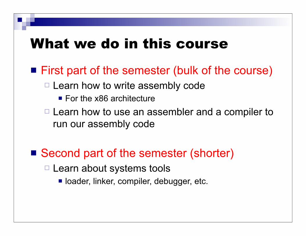
What we do in this course
First part of the semester (bulk of the course) Learn how to write assembly code
For the x86 architecture Learn how to use an assembler and a compiler to
run our assembly code
Second part of the semester (shorter) Learn about systems tools
loader, linker, compiler, debugger, etc.

Why should we learn all this? Why should we learn how to write assembly code?
Students: “We won’t write assembly code for a living!” Reason #1: Many of you will have to write some assembly
Write small piece of assembly for performance optimization as part of larger software projects
Write assembly code for embedded devices Reason #2: Learning assembly makes you a better
programmer in high-level languages Makes you keenly aware of what happens under the cover,
which allows for easier debugging Makes you understand “performance bugs” Allows you to write more efficient high-level code Allows you to read generated assembly to better understand
what’s going on
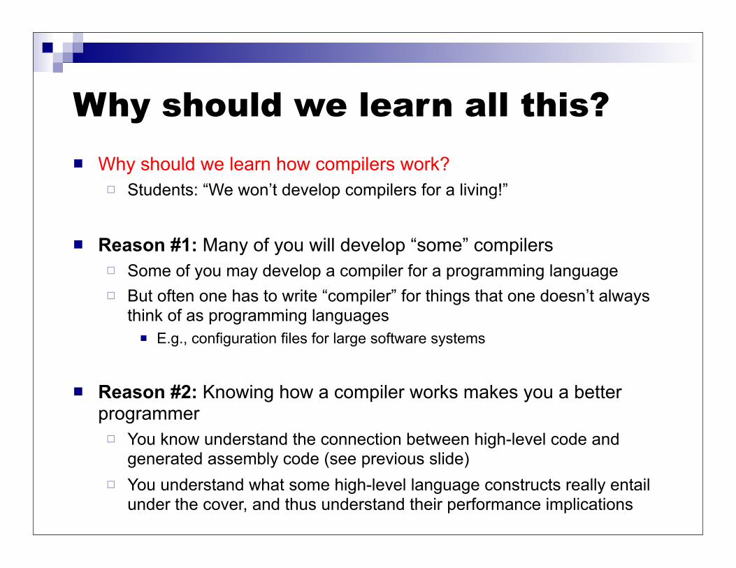
Why should we learn all this? Why should we learn how compilers work?
Students: “We won’t develop compilers for a living!”
Reason #1: Many of you will develop “some” compilers Some of you may develop a compiler for a programming language But often one has to write “compiler” for things that one doesn’t always
think of as programming languages E.g., configuration files for large software systems
Reason #2: Knowing how a compiler works makes you a better programmer You know understand the connection between high-level code and
generated assembly code (see previous slide) You understand what some high-level language constructs really entail
under the cover, and thus understand their performance implications

Why should we learn all this? Meta-reason: this course should go a long way in
giving you a holistic understanding of how a program goes from just a text file to a running code You should be able to describe in low-level details how you
go from “I wrote a piece of C code that calls a function that adds 2 and 2 together and prints the result” to “the computer prints 4”
The complexity of such a simple thing is actually quite stunning, and we’ll take a simplified view
There should be something satisfying in knowing how things work from top to bottom!
This “holistic understanding” should be acquired with ICS312, ICS331, ICS431/EE461, and ICS332

Conclusion
If you want to know more Take a computer architecture
course Classic Textbook: Computer
Organization and Design, Fourth Edition: The Hardware/Software Interface (Patterson and Hennessy, Morgan Kaufmann)